optimove 2 powder reciprocator control for … setting the bridges on the control board (pcb) : ac...
TRANSCRIPT

OptiMove 2 - AC 67
Issu
ed 0
6/00
Operating Instructions and Spare Parts List
OptiMove 2 Powder Reciprocator Control
for Reciprocators with AC Motors
E

OptiMove 2 - AC
Issu
ed 0
6/00
OptiMove 2 - AC 65
Issu
ed 0
6/00
Table of contents
1. OptiMove 2 Powder Reciprocator control . . . . . . . . . . . . . . . . . . . . . . . . . . . . . . . . 11.1 Special characteristics . . . . . . . . . . . . . . . . . . . . . . . . . . . . . . . . . . . . . . 11.2 Axis control system with OptiMove 2 . . . . . . . . . . . . . . . . . . . . . . . . . . 2
2. Start-up . . . . . . . . . . . . . . . . . . . . . . . . . . . . . . . . . . . . . . . . . . . . . . . . . . . . . . . . . . . 32.1 Cable connections on the axis control system and OptiMove 2 . . . . . . 32.2 Hardware versions of the OptiMove 2 . . . . . . . . . . . . . . . . . . . . . . . . . . 4
2.2.1 OptiMove 2 - Housing version . . . . . . . . . . . . . . . . . . . . . . . . . . 42.2.2 OptiMove 2 - Rack version . . . . . . . . . . . . . . . . . . . . . . . . . . . . . 52.2.3 Front display with mounting frame (Rack version) . . . . . . . . . . . 6
2.3 Selection of the Mains input voltage . . . . . . . . . . . . . . . . . . . . . . . . . . . 72.4 Setting the bridges on the control board (PCB) : AC operation only . . . . 82.5 Display and keypad fields . . . . . . . . . . . . . . . . . . . . . . . . . . . . . . . . . . . . 92.6 Symbols on the display . . . . . . . . . . . . . . . . . . . . . . . . . . . . . . . . . . . . . 102.7 Keypad symbols . . . . . . . . . . . . . . . . . . . . . . . . . . . . . . . . . . . . . . . . . . 112.8 Keypad combinations . . . . . . . . . . . . . . . . . . . . . . . . . . . . . . . . . . . . . . 122.9 RAM Reset . . . . . . . . . . . . . . . . . . . . . . . . . . . . . . . . . . . . . . . . . . . . . . 132.10 Checking the Software version . . . . . . . . . . . . . . . . . . . . . . . . . . . . . . . 132.11 Setting the system parameters . . . . . . . . . . . . . . . . . . . . . . . . . . . . . . 14
2.11.1 System parameter 1 : Setting the upper stroke limit . . . . . . . . 152.11.2 System parameter 2 : Reference point . . . . . . . . . . . . . . . . . . 17
3. Programming the OptiMove 2 . . . . . . . . . . . . . . . . . . . . . . . . . . . . . . . . . . . . . . . . 183.1 Programming levels . . . . . . . . . . . . . . . . . . . . . . . . . . . . . . . . . . . . . . . 20
3.1.1 START . . . . . . . . . . . . . . . . . . . . . . . . . . . . . . . . . . . . . . . . . . . . 203.1.2 EDIT . . . . . . . . . . . . . . . . . . . . . . . . . . . . . . . . . . . . . . . . . . . . . 213.1.3 SET UP . . . . . . . . . . . . . . . . . . . . . . . . . . . . . . . . . . . . . . . . . . . 213.1.4 SYSTEM PARAMETER . . . . . . . . . . . . . . . . . . . . . . . . . . . . . . . 22
3.2 Structure of a program step (Procedure step) . . . . . . . . . . . . . . . . . . . 233.2.1 Program parameters on the display . . . . . . . . . . . . . . . . . . . . . 24
3.3 Programming examples . . . . . . . . . . . . . . . . . . . . . . . . . . . . . . . . . . . . 253.3.1 Positioning example . . . . . . . . . . . . . . . . . . . . . . . . . . . . . . . . . 253.3.2 Example for oscillating movements . . . . . . . . . . . . . . . . . . . . . 263.3.3 Distance/Time diagram - Example . . . . . . . . . . . . . . . . . . . . . . 273.3.4 Using the function output . . . . . . . . . . . . . . . . . . . . . . . . . . . . . 28
3.4 Program switching . . . . . . . . . . . . . . . . . . . . . . . . . . . . . . . . . . . . . . . . 293.5 Continuous . . . . . . . . . . . . . . . . . . . . . . . . . . . . . . . . . . . . . . . . . . . . . . 30
4. Automatic operation through an external control . . . . . . . . . . . . . . . . . . . . . . . . . . 324.1 Function . . . . . . . . . . . . . . . . . . . . . . . . . . . . . . . . . . . . . . . . . . . . . . . . 324.2 Switching from Manual to Automatic . . . . . . . . . . . . . . . . . . . . . . . . . . 324.3 Travel to Reference point with an external control . . . . . . . . . . . . . . . . 334.4 Program selection with an external control . . . . . . . . . . . . . . . . . . . . . 334.5 START and STOP with an external control . . . . . . . . . . . . . . . . . . . . . . 354.6 Alarm Input . . . . . . . . . . . . . . . . . . . . . . . . . . . . . . . . . . . . . . . . . . . . . . 364.7 Function output . . . . . . . . . . . . . . . . . . . . . . . . . . . . . . . . . . . . . . . . . . . 364.8 "Program run" signal . . . . . . . . . . . . . . . . . . . . . . . . . . . . . . . . . . . . . . . 364.9 Collective error messages . . . . . . . . . . . . . . . . . . . . . . . . . . . . . . . . . . 37
(continued)
OptiMove 2 - AC66
Issu
ed 0
6/00
Table of Contents (continued)
5. Connections and plug assignment . . . . . . . . . . . . . . . . . . . . . . . . . . . . . . . . . . . . . 385.1 Housing version . . . . . . . . . . . . . . . . . . . . . . . . . . . . . . . . . . . . . . . . . . 385.2 Mounting in a switch cabinet . . . . . . . . . . . . . . . . . . . . . . . . . . . . . . . . 395.3 Mains supply - POWER IN (BP 1-, BP 2 - X1) . . . . . . . . . . . . . . . . . . . . 405.4 External digital control signal (CONTROL-INPUT-OUTPUT) . . . . . . . . . 41
5.4.1 Digital inputs and outputs . . . . . . . . . . . . . . . . . . . . . . . . . . . . . 425.4.2 Electrical connection for a digital output . . . . . . . . . . . . . . . . . . 435.4.3 Electrical connection for a digital input . . . . . . . . . . . . . . . . . . . 44
5.5 Incremental pulse generator connections for synchronization - SYNCH 455.5.1 Electrical specification of the incremental pulse generator
for synchronization (Conveyor cycle generation) . . . . . . . . . . . 465.5.2 Connection example for the synchronization of multiple axes . 47
5.6 Positioning - POS . . . . . . . . . . . . . . . . . . . . . . . . . . . . . . . . . . . . . . . . . 485.7 Drive control - DRIVE . . . . . . . . . . . . . . . . . . . . . . . . . . . . . . . . . . . . . . 495.8 Keypad display connections . . . . . . . . . . . . . . . . . . . . . . . . . . . . . . . . . 50
6. Synchronization of the conveyor cycle . . . . . . . . . . . . . . . . . . . . . . . . . . . . . . . . . . 516.1 Function . . . . . . . . . . . . . . . . . . . . . . . . . . . . . . . . . . . . . . . . . . . . . . . . 516.2 Start-up of the conveyor cycle synchronization . . . . . . . . . . . . . . . . . . 52
6.2.1 Contact assignment of the PS 2 Supplementary powersupply for SYNCH (Conveyor cycle generation) . . . . . . . . . . . . 52
6.3 Guide lines for fitting the incremental pulse generatorto the conveyor . . . . . . . . . . . . . . . . . . . . . . . . . . . . . . . . . . . . . . . . . . . 546.3.1 Instructions for fitting the incremental pulse generator . . . . . . 55
6.4 System parameters for synchronization . . . . . . . . . . . . . . . . . . . . . . . . 566.5 Digital control signals for synchronization . . . . . . . . . . . . . . . . . . . . . . . 57
6.5.1 Conveyor cycle outputs . . . . . . . . . . . . . . . . . . . . . . . . . . . . . . 57
7. Error messages . . . . . . . . . . . . . . . . . . . . . . . . . . . . . . . . . . . . . . . . . . . . . . . . . . . 64
Appendix A : Spare Parts
Appendix B : Table for system parameters
Appendix C : OptiMove 2 Program parameters
Appendix D : MICRO 3 Control board configuration possibilities
Page
OptiMove 2 - AC 63
Issu
ed 0
6/00
Safety regulations
1. The OptiMove 2 Powder Reciprocator Control should only be switched onand operated afterafterafterafterafter these Operating Instructions have been read throughthoroughly.Incorrect operation of the OptiMove 2 Control can lead to accidents,malfunctions and/or damage to the equipment.
2. ATTENTION! The power of the reciprocator motor is very much greater
than that of a human!
All axes must be protected from access during operation (see local safetyregulations).If the Reciprocator Control switches off, the carriage can slowly sink to theZero point, also by stillstand of the carriage, therefore, never stand under thecarriage!
3. The plug connections between the OptiMove 2 Reciprocator Control, thefrequency converter, and the Reciprocator should only be disconnectedwhen the OptiMove 2 Reciprocator Control is switched off.
4. The connecting cables between the frequency converter and theReciprocator must be laid out so that during operation the axis cannot bedamaged.Observe local safety regulations!
5. The upper stroke limit must always be set within the height of the
Reciprocator. If an incorrect stroke limit is set (too high) this can lead todamage to the Reciprocator and/or the Booth!
6. When repairs are carried out on the Reciprocator, the OptiMove 2Reciprocator Control, and the power supply must always be disconnectedfrom the Mains according to local safety regulations!

OptiMove 2 - AC64
Issu
ed 0
6/00
Technical Data
OptiMove 2 Powder Reciprocator control
Number of axes per module : 1
Number of axes per control unit : 1
Maximum available programs : 64
Max. stroke height (Theoretical) : 9.999 m.
Positioning error : < 1 mm.
Maximum speed : 0.6 m/s.
Minimum speed : 0.05 m/s.
Acceleration : 1.5 m/s2.
Voltage range selection : 100V*, 110V, 120V, 200V*, 220V, 230V, 240V(*Configuration changes to the PS 1 Powersupply are necessary).
Voltage tolerances : ±10 %
Frequency : 48 - 62 Hz
Fuses : 100 - 120V : F1, F2 = 10A (slow), F3 = 500 mA200 - 240V : F1, F2 = 5A (slow), F3 = 250 mA
Power consumption : 30 W(OptiMove 2 Control unit without the power
supply)
Operating temperatures : 0 oC to +40 oC (+32 oF to +104 oF)
Storage temperatures : -20 oC to +70 oC (-4 oF to +158 oF)
Type of protection : IP 54
Dimensions : Width : 425 mmDepth : 270 mmHeight : 88 mmWeight : 6.2 kg
OptiMove 2 - AC 1
Issu
ed 0
6/00
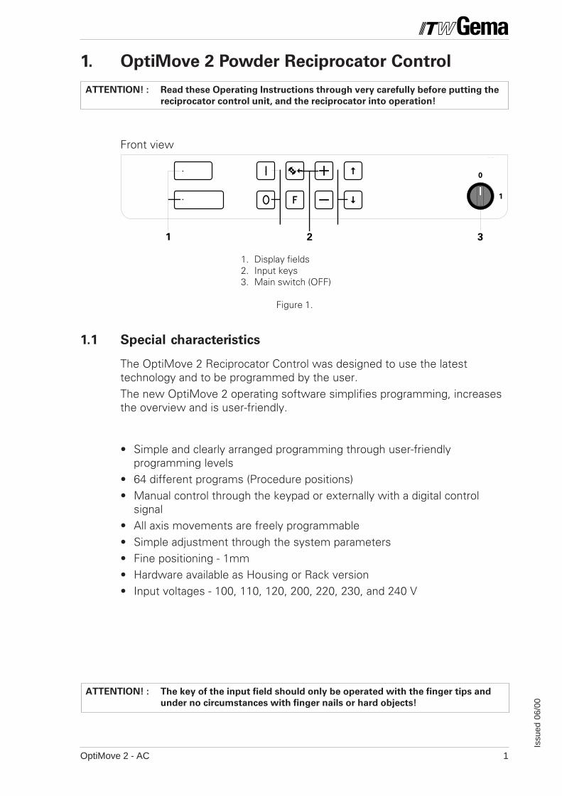
1. OptiMove 2 Powder Reciprocator Control
Front view
1. Display fields2. Input keys3. Main switch (OFF)
Figure 1.
1.1 Special characteristics
The OptiMove 2 Reciprocator Control was designed to use the latesttechnology and to be programmed by the user.The new OptiMove 2 operating software simplifies programming, increasesthe overview and is user-friendly.
• Simple and clearly arranged programming through user-friendlyprogramming levels
• 64 different programs (Procedure positions)• Manual control through the keypad or externally with a digital control
signal• All axis movements are freely programmable• Simple adjustment through the system parameters• Fine positioning - 1mm• Hardware available as Housing or Rack version• Input voltages - 100, 110, 120, 200, 220, 230, and 240 V
ATTENTION! : Read these Operating Instructions through very carefully before putting the
reciprocator control unit, and the reciprocator into operation!
ATTENTION! : The key of the input field should only be operated with the finger tips and
under no circumstances with finger nails or hard objects!
GEMAVOLSTATIC
PRC 2
1
0
1 2 3
3
OptiMove 2 - AC2
Issu
ed 0
6/00
M I
Figure 2.
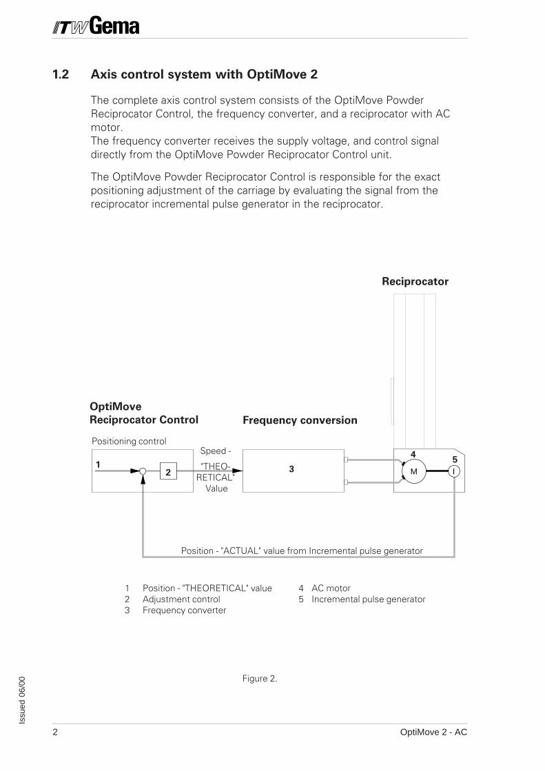
1.2 Axis control system with OptiMove 2
The complete axis control system consists of the OptiMove PowderReciprocator Control, the frequency converter, and a reciprocator with ACmotor.The frequency converter receives the supply voltage, and control signaldirectly from the OptiMove Powder Reciprocator Control unit.
The OptiMove Powder Reciprocator Control is responsible for the exactpositioning adjustment of the carriage by evaluating the signal from thereciprocator incremental pulse generator in the reciprocator.
Positioning control
OptiMove
Reciprocator Control Frequency conversion
Reciprocator
Position - "ACTUAL" value from Incremental pulse generator
3
45
Speed -
"THEO-RETICAL"
Value
12
1 Position - "THEORETICAL" value 4 AC motor2 Adjustment control 5 Incremental pulse generator3 Frequency converter
OptiMove 2 - AC 3
Issu
ed 0
6/00
F1
F2
F3
4321 5
1 2 3
4
6
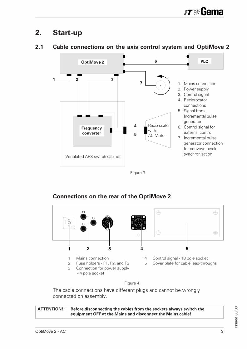
ATTENTION! : Before disconnecting the cables from the sockets always switch the
equipment OFF at the Mains and disconnect the Mains cable!
OptiMove 2 PLC
1 Mains connection 4 Control signal - 18 pole socket2 Fuse holders - F1, F2, and F3 5 Cover plate for cable lead-throughs3 Connection for power supply
- 4 pole socket
Figure 4.
2. Start-up
2.1 Cable connections on the axis control system and OptiMove 2
The cable connections have different plugs and cannot be wronglyconnected on assembly.
Connections on the rear of the OptiMove 2
Frequency
converter
7
Figure 3.
ReciprocatorwithAC Motor
Ventilated APS switch cabinet
5
1. Mains connection2. Power supply3. Control signal4 Reciprocator
connections5. Signal from
Incremental pulsegenerator
6. Control signal forexternal control
7. Incremental pulsegenerator connectionfor conveyor cyclesynchronization
OptiMove 2 - AC4
Issu
ed 0
6/00
GEMAVOLSTATIC
PRC 3
1
0
88
425
F1
F2
F3
88
425
425
270
Figure 5.
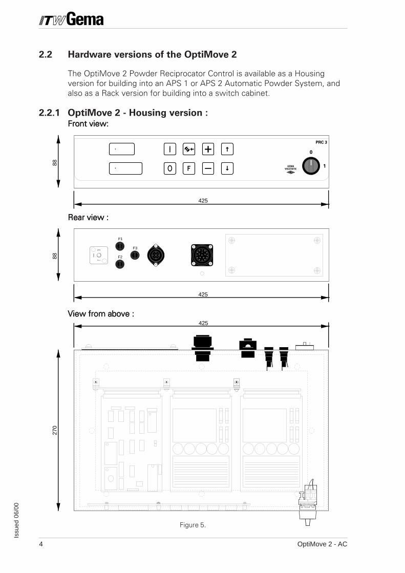
2.2 Hardware versions of the OptiMove 2
The OptiMove 2 Powder Reciprocator Control is available as a Housingversion for building into an APS 1 or APS 2 Automatic Powder System, andalso as a Rack version for building into a switch cabinet.
2.2.1 OptiMove 2 - Housing version :Front view:Front view:Front view:Front view:Front view:
Rear view :Rear view :Rear view :Rear view :Rear view :
View from above :View from above :View from above :View from above :View from above :
OptiMove 2 - AC 5
Issu
ed 0
6/00
482.6
70
300
14 TE
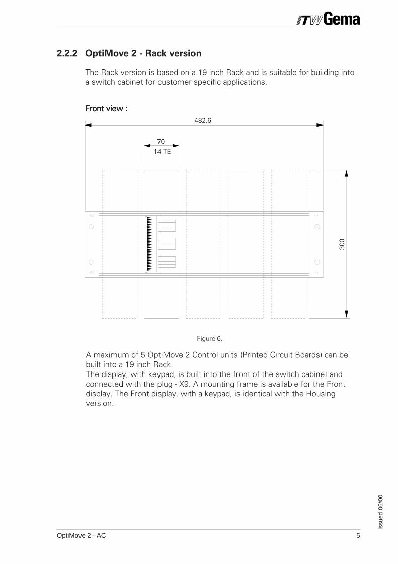
2.2.2 OptiMove 2 - Rack version
The Rack version is based on a 19 inch Rack and is suitable for building intoa switch cabinet for customer specific applications.
Front view :Front view :Front view :Front view :Front view :
A maximum of 5 OptiMove 2 Control units (Printed Circuit Boards) can bebuilt into a 19 inch Rack.The display, with keypad, is built into the front of the switch cabinet andconnected with the plug - X9. A mounting frame is available for the Frontdisplay. The Front display, with a keypad, is identical with the Housingversion.
Figure 6.
OptiMove 2 - AC6
Issu
ed 0
6/00
75313131
265,5
40
52,5
19
19
22
22
1390
5
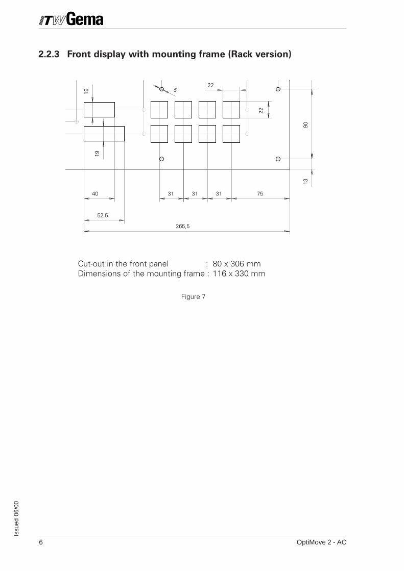
2.2.3 Front display with mounting frame (Rack version)
Cut-out in the front panel : 80 x 306 mmDimensions of the mounting frame : 116 x 330 mm
Figure 7
OptiMove 2 - AC 7
Issu
ed 0
6/00
2.3 Selection of the Mains input voltage
Before the OptiMove 2 Powder Reciprocator Control is connected to theMains, the built-in Mains section must be adapted to the available Mains
voltage.
ATTENTION!! A voltage 10% or more over or under the nominal value can lead to
malfunctioning or damage to the control electronics.
Input voltage range : 100 V, 110 V, 120 V, 200 V, 220 V, 230 V, and 240 V
In order to set the Input voltage of the OptiMove 2, proceed as follows :
1. Disconnect all the electrical connections on the rear of the control unitand pull out the control unit.
2. Unscrew the quick-release screws on the cover of the control unit a halfturn and remove the cover.
3. The connections and bridges on the 10 pole plug - X1 on the Back planemust now be wired to correspond with the selected voltage.
(See Chapter 5.3 - Mains supply - POWER IN)
OptiMove 2 - AC8
Issu
ed 0
6/00
B X
20 A
A X25 B
A X24 B
A X21 B
B X22 A
B X27 A
B X
26 A
INT 0
INT 1B
X23
A
Bridge Pos. B
Bridge Pos. ABridge Pos. A
Bridge Pos. ABridge Pos. B
Bridge Pos. B
Bridge Pos. A
Bridge Pos. B
Bridge setBridge set
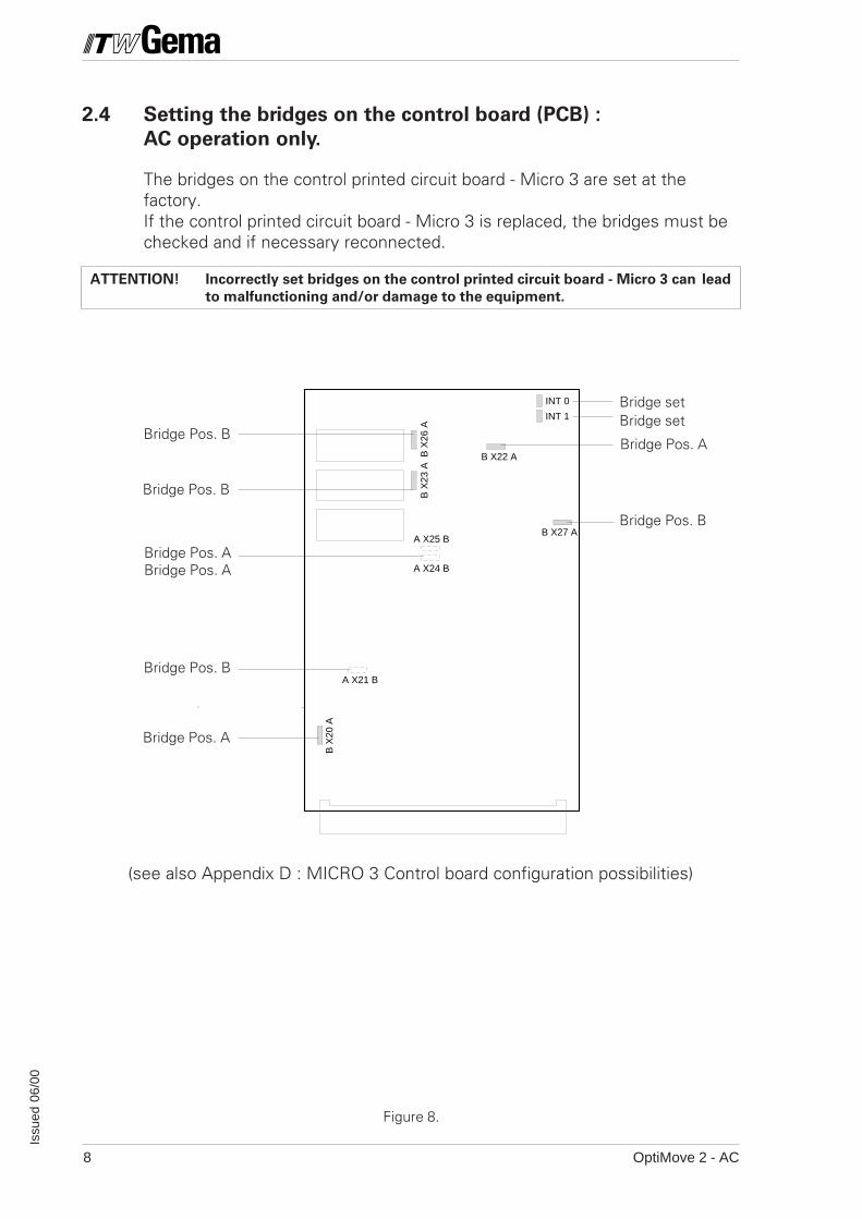
(see also Appendix D : MICRO 3 Control board configuration possibilities)
Figure 8.
2.4 Setting the bridges on the control board (PCB) :
AC operation only.
The bridges on the control printed circuit board - Micro 3 are set at thefactory.If the control printed circuit board - Micro 3 is replaced, the bridges must bechecked and if necessary reconnected.
ATTENTION! Incorrectly set bridges on the control printed circuit board - Micro 3 can lead
to malfunctioning and/or damage to the equipment.
OptiMove 2 - AC 9
Issu
ed 0
6/00
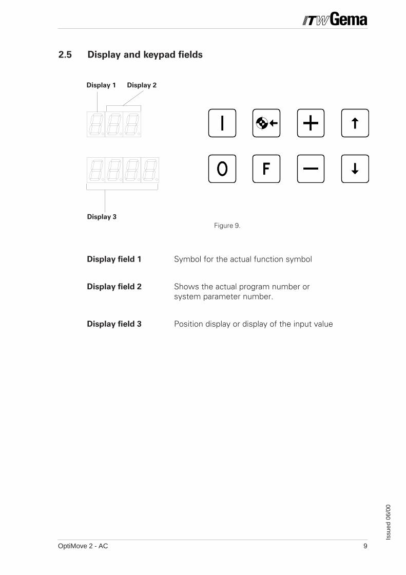
Display 1 Display 2
Display 3
Figure 9.
2.5 Display and keypad fields
Display field 1 Symbol for the actual function symbol
Display field 2 Shows the actual program number orsystem parameter number.
Display field 3 Position display or display of the input value
OptiMove 2 - AC10
Issu
ed 0
6/00
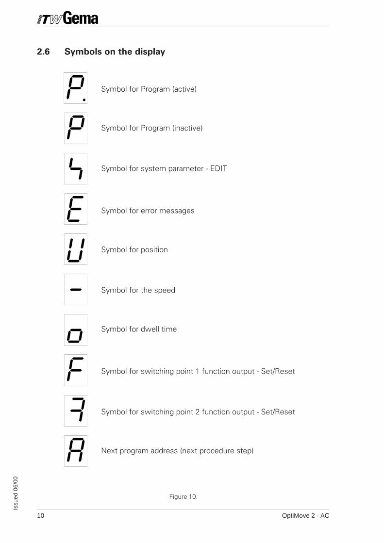
2.6 Symbols on the display
Symbol for Program (active)
Symbol for Program (inactive)
Symbol for system parameter - EDIT
Symbol for error messages
Symbol for position
Symbol for the speed
Symbol for dwell time
Symbol for switching point 1 function output - Set/Reset
Symbol for switching point 2 function output - Set/Reset
Next program address (next procedure step)
Figure 10.
OptiMove 2 - AC 11
Issu
ed 0
6/00
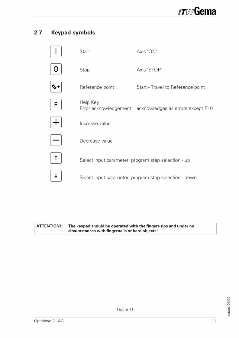
2.7 Keypad symbols
Start Axis "ON"
Stop Axis "STOP"
Reference point Start - Travel to Reference point
Help KeyError acknowledgement acknowledges all errors except E10
Increase value
Decrease value
Select input parameter, program step selection - up
Select input parameter, program step selection - down
ATTENTION! : The keypad should be operated with the fingers tips and under no
circumstances with fingernails or hard objects!
Figure 11.
OptiMove 2 - AC12
Issu
ed 0
6/00
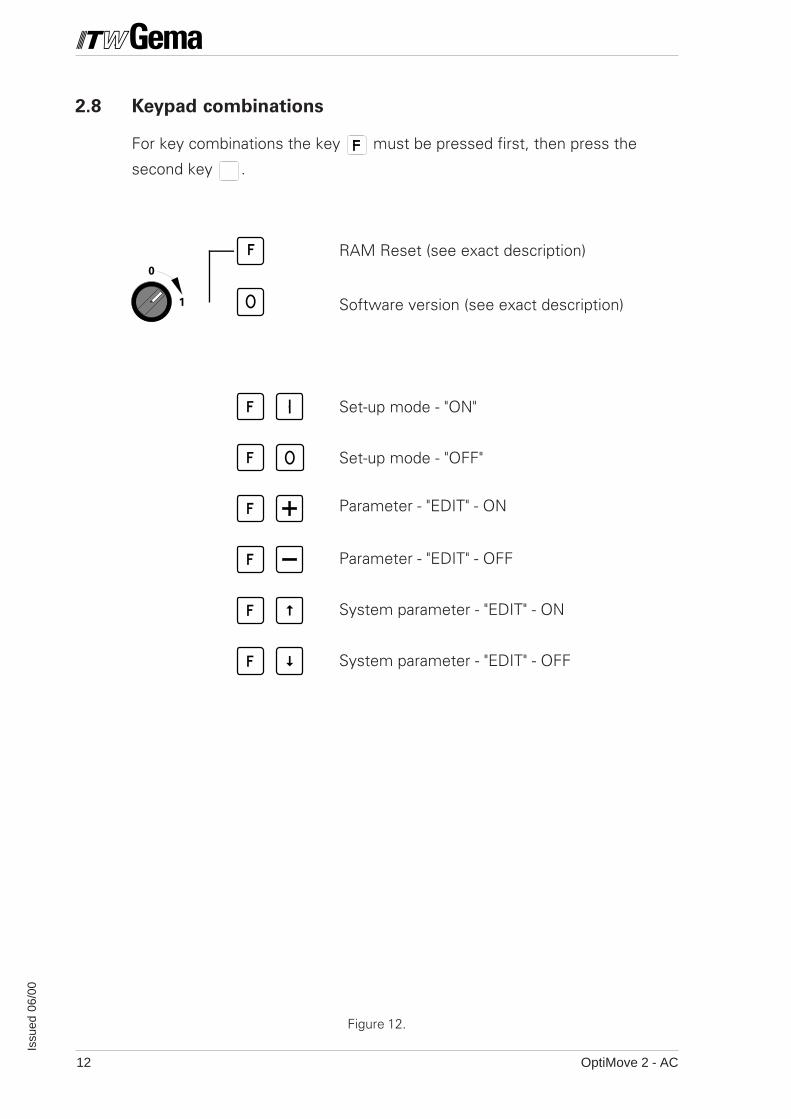
2.8 Keypad combinations
For key combinations the key must be pressed first, then press the
second key .
RAM Reset (see exact description)
Software version (see exact description)
Set-up mode - "ON"
Set-up mode - "OFF"
Parameter - "EDIT" - ON
Parameter - "EDIT" - OFF
System parameter - "EDIT" - ON
System parameter - "EDIT" - OFF
1
0
Figure 12.
OptiMove 2 - AC 13
Issu
ed 0
6/00
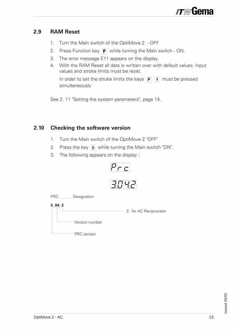
PRC Designation
3. 04. 2
2.10 Checking the software version
1. Turn the Main switch of the OptiMove 2 "OFF"
2. Press the key while turning the Main switch "ON".
3. The following appears on the display :
Version number
2: for AC Reciprocator
PRC version
2.9 RAM Reset
1. Turn the Main switch of the OptiMove 2 - OFF
2. Press Function key while turning the Main switch - ON.
3. The error message E11 appears on the display.4. With the RAM Reset all data is written over with default values. Input
values and stroke limits must be reset.
In order to set the stroke limits the keys must be pressedsimultaneously
See 2. 11 "Setting the system parameters", page 14.
OptiMove 2 - AC14
Issu
ed 0
6/00
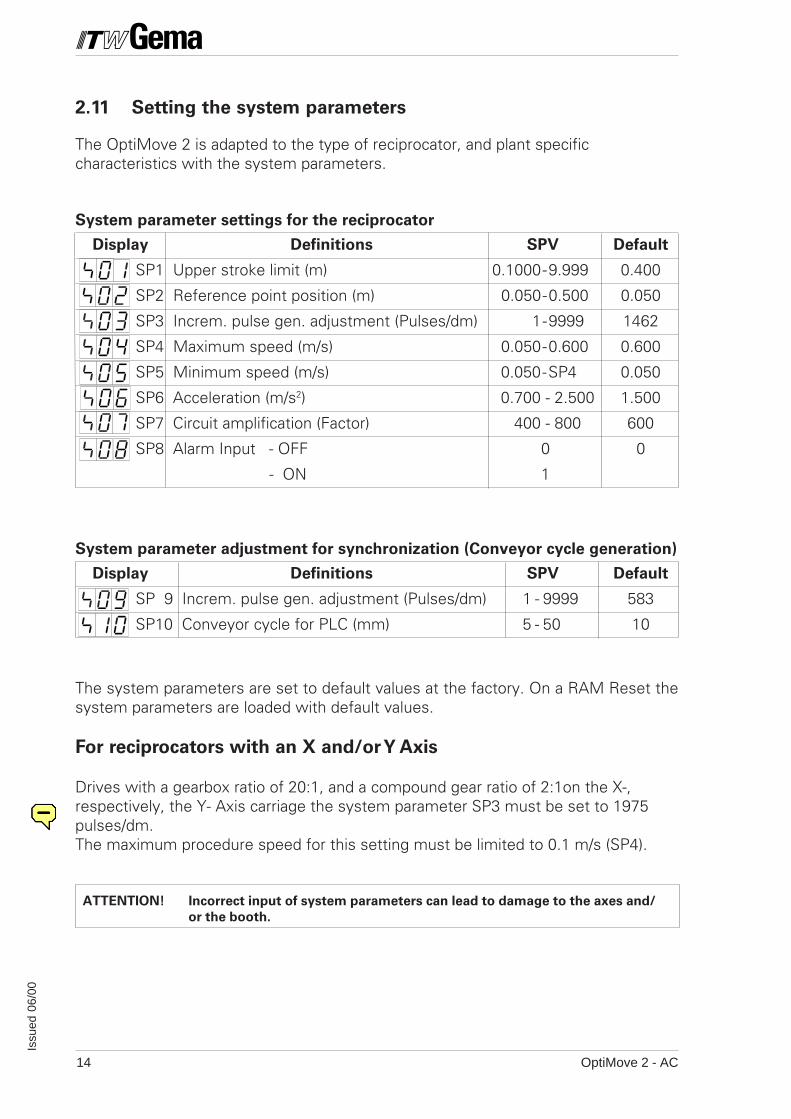
2.11 Setting the system parameters
The OptiMove 2 is adapted to the type of reciprocator, and plant specificcharacteristics with the system parameters.
System parameter settings for the reciprocator
Display Definitions SPV Default
SP1 Upper stroke limit (m) 0.1000-9.999 0.400
SP2 Reference point position (m) 0.050-0.500 0.050
SP3 Increm. pulse gen. adjustment (Pulses/dm) 1-9999 1462
SP4 Maximum speed (m/s) 0.050-0.600 0.600
SP5 Minimum speed (m/s) 0.050-SP4 0.050
SP6 Acceleration (m/s2) 0.700 - 2.500 1.500
SP7 Circuit amplification (Factor) 400 - 800 600
SP8 Alarm Input - OFF 0 0
- ON 1
System parameter adjustment for synchronization (Conveyor cycle generation)
Display Definitions SPV Default
SP 9 Increm. pulse gen. adjustment (Pulses/dm) 1 - 9999 583
SP10 Conveyor cycle for PLC (mm) 5 - 50 10
The system parameters are set to default values at the factory. On a RAM Reset thesystem parameters are loaded with default values.
For reciprocators with an X and/or Y Axis
Drives with a gearbox ratio of 20:1, and a compound gear ratio of 2:1on the X-,respectively, the Y- Axis carriage the system parameter SP3 must be set to 1975pulses/dm.The maximum procedure speed for this setting must be limited to 0.1 m/s (SP4).
ATTENTION! Incorrect input of system parameters can lead to damage to the axes and/
or the booth.
OptiMove 2 - AC 15
Issu
ed 0
6/00
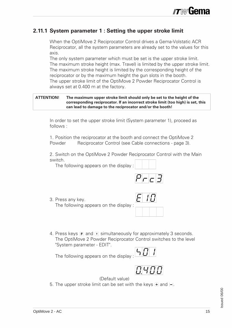
2.11.1 System parameter 1 : Setting the upper stroke limit
When the OptiMove 2 Reciprocator Control drives a Gema-Volstatic ACRReciprocator, all the system parameters are already set to the values for thisaxis.The only system parameter which must be set is the upper stroke limit.The maximum stroke height (max. Travel) is limited by the upper stroke limit.The maximum stroke height is limited by the corresponding height of thereciprocator or by the maximum height the gun slots in the booth.The upper stroke limit of the OptiMove 2 Powder Reciprocator Control isalways set at 0.400 m at the factory.
ATTENTION! The maximum upper stroke limit should only be set to the height of the
corresponding reciprocator. If an incorrect stroke limit (too high) is set, this
can lead to damage to the reciprocator and/or the booth!
In order to set the upper stroke limit (System parameter 1), proceed asfollows :
1. Position the reciprocator at the booth and connect the OptiMove 2Powder Reciprocator Control (see Cable connections - page 3).
2. Switch on the OptiMove 2 Powder Reciprocator Control with the Mainswitch.
The following appears on the display :
3. Press any key.The following appears on the display :
4. Press keys and simultaneously for approximately 3 seconds.The OptiMove 2 Powder Reciprocator Control switches to the level"System parameter - EDIT".
The following appears on the display :
(Default value)5. The upper stroke limit can be set with the keys and .

OptiMove 2 - AC16
Issu
ed 0
6/00
6. If the other system parameters must be edited, these can be selectedwith the key or .
7. Press the two keys, and simultaneously.The OptiMove 2 Powder Reciprocator Control exits from the systemparameter "Upper stroke limit".The following appears on the display:
The "Travel to Reference point" must restarted.
If the system parameters must be changed, fill in the actual values in thecorresponding table in Appendix B.
ATTENTION! Incorrect inputs can lead to damage to the reciprocator and/or the booth!
OptiMove 2 - AC 17
Issu
ed 0
6/00
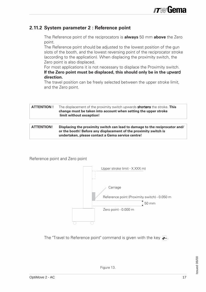
Carriage
50 mm
Upper stroke limit - X.XXX m)
Zero point - 0.000 m
The "Travel to Reference point" command is given with the key .
Reference point (Proximity switch) - 0.050 m
2.11.2 System parameter 2 : Reference point
The Reference point of the reciprocators is always 50 mm above the Zeropoint.The Reference point should be adjusted to the lowest position of the gunslots of the booth, and the lowest reversing point of the reciprocator stroke(according to the application). When displacing the proximity switch, theZero point is also displaced.For most applications it is not necessary to displace the Proximity switch.If the Zero point must be displaced, this should only be in the upwardupwardupwardupwardupwarddirection.
The travel position can be freely selected between the upper stroke limit,and the Zero point.
ATTENTION ! The displacement of the proximity switch upwards shortensshortensshortensshortensshortens the stroke. This
change must be taken into account when setting the upper stroke
limit without exception!
ATTENTION! Displacing the proximity switch can lead to damage to the reciprocator and/
or the booth! Before any displacement of the proximity switch is
undertaken, please contact a Gema service centre!
Reference point and Zero point
Figure 13.

OptiMove 2 - AC18
Issu
ed 0
6/00
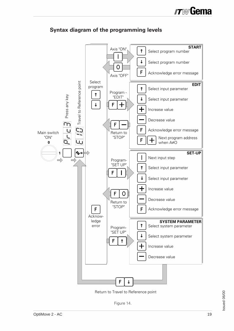
3. Programming the OptiMove 2
The operating software of the OptiMove 2 is set out for the user in 5programming levels.
These are : • STOP• START• EDIT• SET UP• SYSTEM PARAMETER
Each of these program levels has exactly defined functions.The individual program levels can be selected with a single key or a keycombination.
The structure in the form of a syntax diagram is graphically illustrated on thefollowing pages. A careful study of this diagram will greatly help in under-standing the programming steps.
OptiMove 2 - AC 19
Issu
ed 0
6/00
1
0
Select program number
Acknowledge error message
Select input parameter
Increase value
Decrease value
Next input step
Axis "ON"
Program -"EDIT"
Return to"STOP"
Program-"SET UP"
Return to"STOP"
Program-"SET UP"
Acknow-ledgeerror
Select program
Return to Travel to Reference point
Trav
el t
o R
efer
ence
poi
nt
Pre
ss a
ny k
ey
Main switch"ON"
Select program number
Select input parameter
Next program address when A≠O
Decrease value
Acknowledge error message
Increase value
Select input parameter
Select input parameter
Select system parameter
Decrease value
Increase value
Acknowledge error message
Select system parameter
Axis "OFF"
SYSTEM PARAMETER
SET-UP
START
EDIT
Syntax diagram of the programming levels
Figure 14.
OptiMove 2 - AC20
Issu
ed 0
6/00
3.1 Programming levels
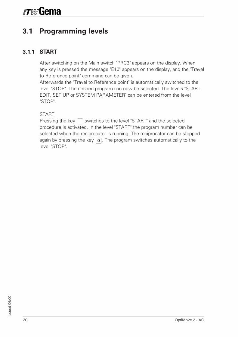
3.1.1 START
After switching on the Main switch "PRC3" appears on the display. Whenany key is pressed the message "E10" appears on the display, and the "Travelto Reference point" command can be given.Afterwards the "Travel to Reference point" is automatically switched to thelevel "STOP". The desired program can now be selected. The levels "START,EDIT, SET UP or SYSTEM PARAMETER" can be entered from the level"STOP".
STARTPressing the key switches to the level "START" and the selectedprocedure is activated. In the level "START" the program number can beselected when the reciprocator is running. The reciprocator can be stoppedagain by pressing the key . The program switches automatically to thelevel "STOP".
OptiMove 2 - AC 21
Issu
ed 0
6/00
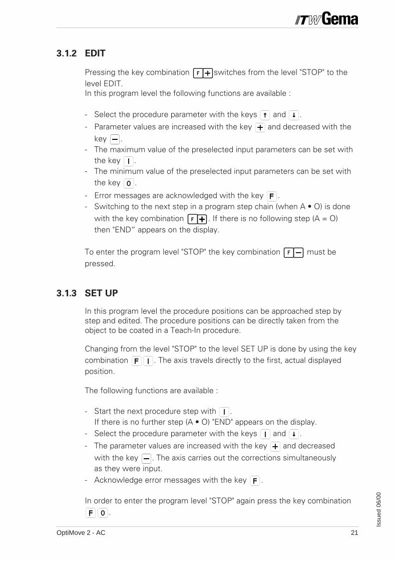
3.1.2 EDIT
Pressing the key combination switches from the level "STOP" to thelevel EDIT.In this program level the following functions are available :
- Select the procedure parameter with the keys and .
- Parameter values are increased with the key and decreased with thekey .
- The maximum value of the preselected input parameters can be set withthe key .
- The minimum value of the preselected input parameters can be set withthe key .
- Error messages are acknowledged with the key .- Switching to the next step in a program step chain (when A • O) is done
with the key combination . If there is no following step (A = O)then "END“ appears on the display.
To enter the program level "STOP" the key combination must bepressed.
3.1.3 SET UP
In this program level the procedure positions can be approached step bystep and edited. The procedure positions can be directly taken from theobject to be coated in a Teach-In procedure.
Changing from the level "STOP" to the level SET UP is done by using the keycombination . The axis travels directly to the first, actual displayedposition.
The following functions are available :
- Start the next procedure step with .If there is no further step (A • O) "END" appears on the display.
- Select the procedure parameter with the keys and .
- The parameter values are increased with the key and decreasedwith the key . The axis carries out the corrections simultaneouslyas they were input.
- Acknowledge error messages with the key .
In order to enter the program level "STOP" again press the key combination.
OptiMove 2 - AC22
Issu
ed 0
6/00
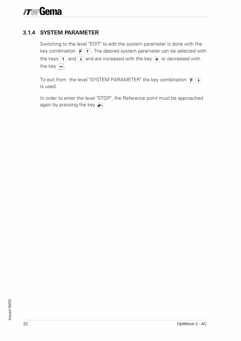
3.1.4 SYSTEM PARAMETER
Switching to the level "EDIT" to edit the system parameter is done with thekey combination . The desired system parameter can be selected with
the keys and and are increased with the key or decreased with
the key .
To exit from the level "SYSTEM PARAMETER" the key combination is used.
In order to enter the level "STOP", the Reference point must be approachedagain by pressing the key .
OptiMove 2 - AC 23
Issu
ed 0
6/00
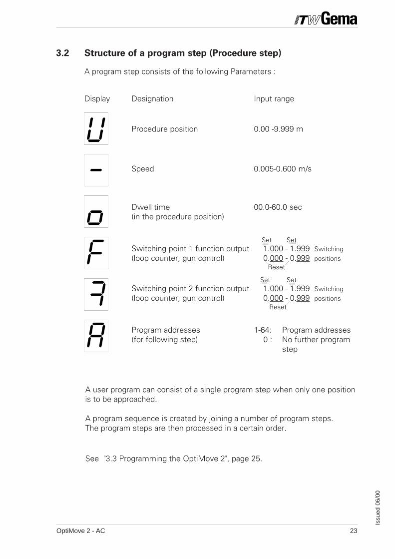
3.2 Structure of a program step (Procedure step)
A program step consists of the following Parameters :
Display Designation Input range
Procedure position 0.00 -9.999 m
Speed 0.005-0.600 m/s
Dwell time 00.0-60.0 sec(in the procedure position)
Set SetSwitching point 1 function output 1.000 - 1.999 Switching(loop counter, gun control) 0.000 - 0.999 positions
Reset
Set SetSwitching point 2 function output 1.000 - 1.999 Switching(loop counter, gun control) 0.000 - 0.999 positions
Reset
Program addresses 1-64: Program addresses(for following step) 0 : No further program
step
A user program can consist of a single program step when only one positionis to be approached.
A program sequence is created by joining a number of program steps.The program steps are then processed in a certain order.
See "3.3 Programming the OptiMove 2", page 25.
OptiMove 2 - AC24
Issu
ed 0
6/00
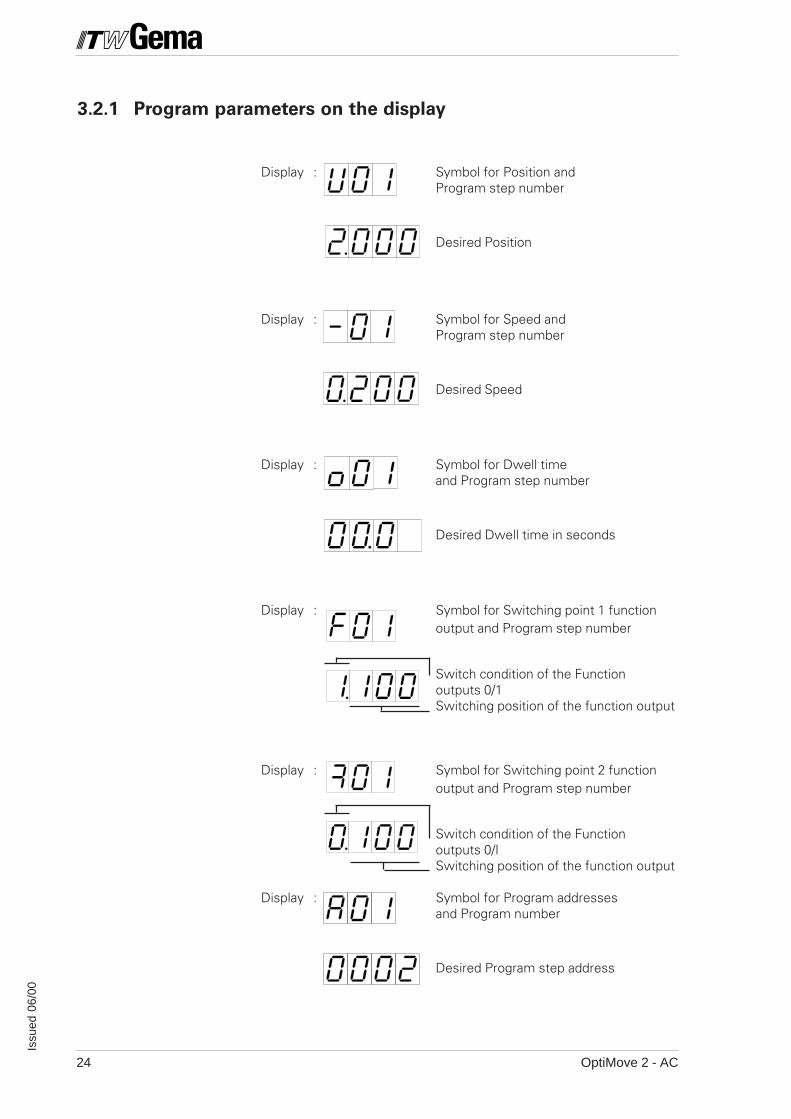
3.2.1 Program parameters on the display
Display : Symbol for Position andProgram step number
Desired Position
Display : Symbol for Speed andProgram step number
Desired Speed
Display : Symbol for Dwell timeand Program step number
Desired Dwell time in seconds
Display : Symbol for Switching point 1 functionoutput and Program step number
Switch condition of the Functionoutputs 0/1Switching position of the function output
Display : Symbol for Switching point 2 functionoutput and Program step number
Switch condition of the Functionoutputs 0/ISwitching position of the function output
Display : Symbol for Program addressesand Program number
Desired Program step address
OptiMove 2 - AC 25
Issu
ed 0
6/00
•
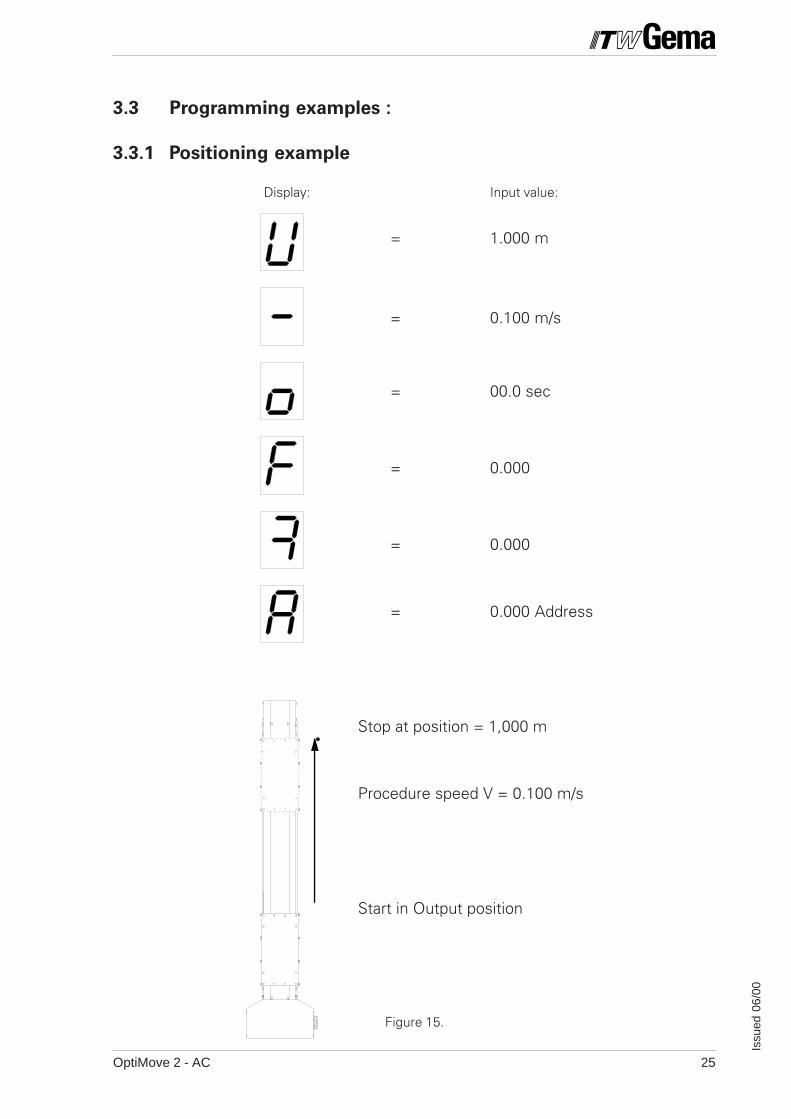
3.3 Programming examples :
3.3.1 Positioning example
Display: Input value:
= 1.000 m
= 0.100 m/s
= 00.0 sec
= 0.000
= 0.000
= 0.000 Address
Stop at position = 1,000 m
Procedure speed V = 0.100 m/s
Start in Output position
Figure 15.
OptiMove 2 - AC26
Issu
ed 0
6/00
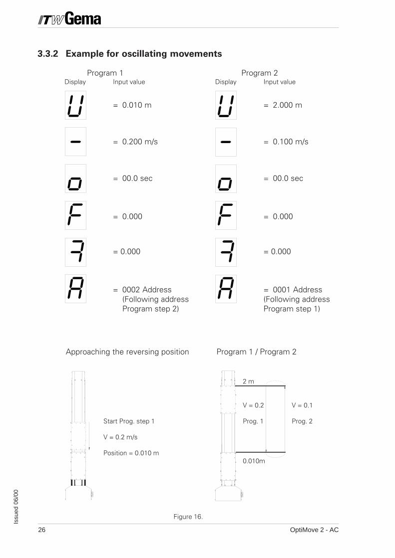
3.3.2 Example for oscillating movements
Program 1 Program 2Display Input value Display Input value
= 0.010 m = 2.000 m
= 0.200 m/s = 0.100 m/s
= 00.0 sec = 00.0 sec
= 0.000 = 0.000
= 0.000 = 0.000
= 0002 Address = 0001 Address(Following address (Following addressProgram step 2) Program step 1)
Approaching the reversing position Program 1 / Program 2
2 m
V = 0.2 V = 0.1
Start Prog. step 1 Prog. 1 Prog. 2
V = 0.2 m/s
Position = 0.010 m0.010m
Figure 16.
OptiMove 2 - AC 27
Issu
ed 0
6/00
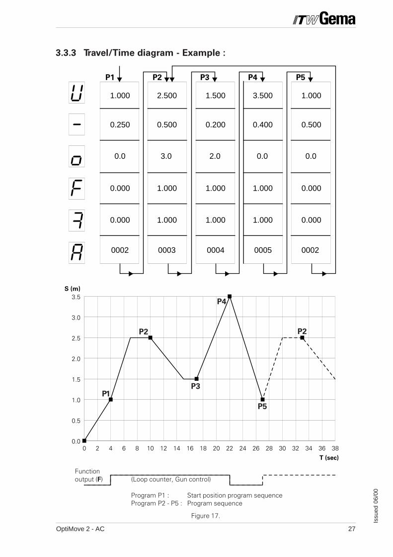
P2
1.000
P1 P3 P4 P5
2.500 1.500 3.500 1.000
0.250 0.500 0.200 0.400 0.500
0002 0003 0004 0005 0002
0.0 3.0 2.0 0.0 0.0
0.000 1.000 1.000 1.000 0.000
0.000 1.000 1.000 1.000 0.000
0 2 4 6 8 10 12 14 16 18 20 22 24 26 28 30 32 34 36 380.0
0.5
1.0
1.5
2.0
2.5
3.0
3.5S (m)
T (sec)
3.3.3 Travel/Time diagram - Example :
Figure 17.
Functionoutput (F) (Loop counter, Gun control)
Program P1 : Start position program sequenceProgram P2 - P5 : Program sequence
P1
P4
P5
P2 P2
P3
OptiMove 2 - AC28
Issu
ed 0
6/00
100 mm 500 mm
HIGH
LOWLOW
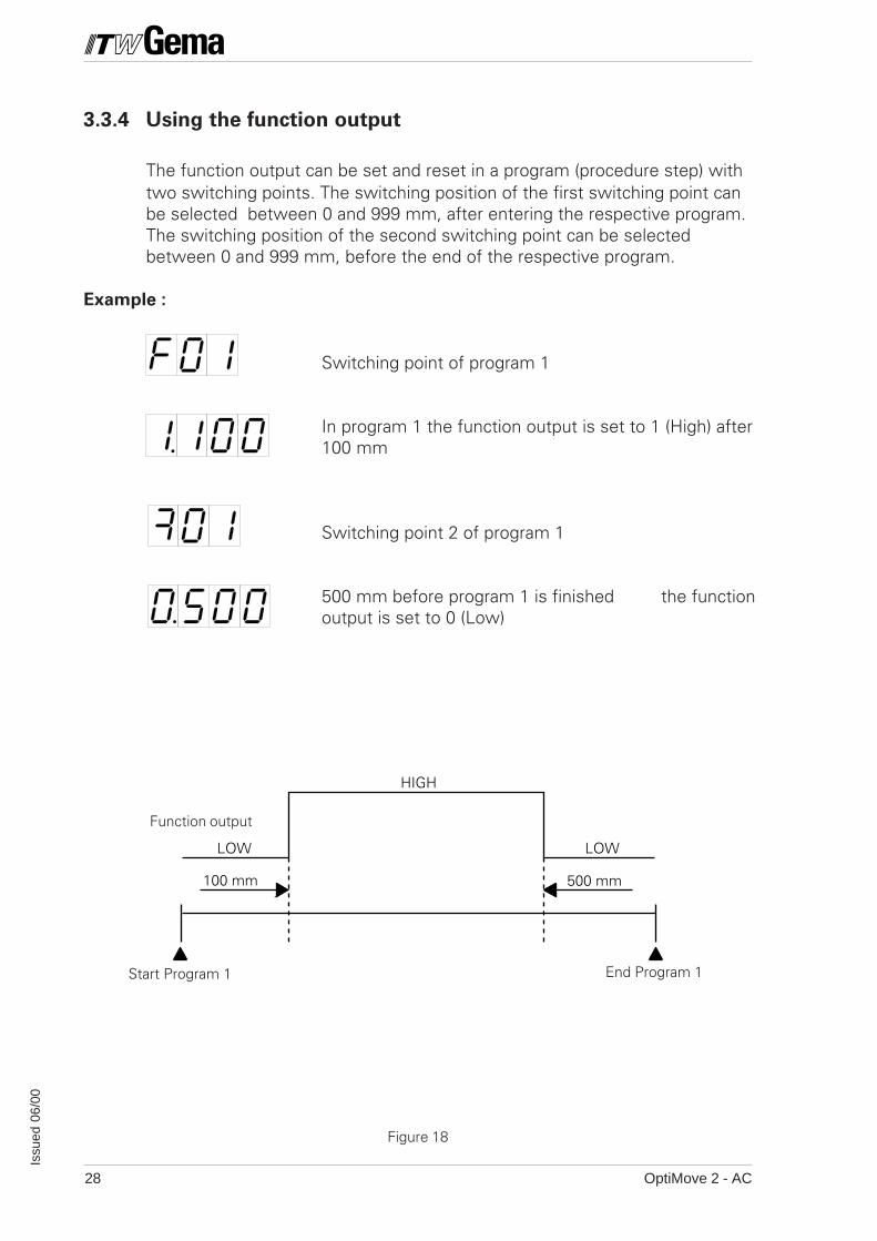
3.3.4 Using the function output
The function output can be set and reset in a program (procedure step) withtwo switching points. The switching position of the first switching point canbe selected between 0 and 999 mm, after entering the respective program.The switching position of the second switching point can be selectedbetween 0 and 999 mm, before the end of the respective program.
Example :
Start Program 1 End Program 1
Function output
Figure 18
Switching point of program 1
In program 1 the function output is set to 1 (High) after100 mm
Switching point 2 of program 1
500 mm before program 1 is finished the functionoutput is set to 0 (Low)
OptiMove 2 - AC 29
Issu
ed 0
6/00
3.4 Program switching
Program switching can be carried out through the keypad (manually) orthrough an external control signal.
If a program switch takes place when the axis is moving, the axis does notstop, but immediately carries out the new program step.When changing speed the acceleration development (Ramp) is taken intoaccount.
If a program change is initiated during an acceleration or braking phase, thenthe acceleration/deceleration ramp development of the old program step iscompleted before the ramp of the following program is carried out. Thedisplay of the actual program number is immediately updated.
OptiMove 2 - AC30
Issu
ed 0
6/00
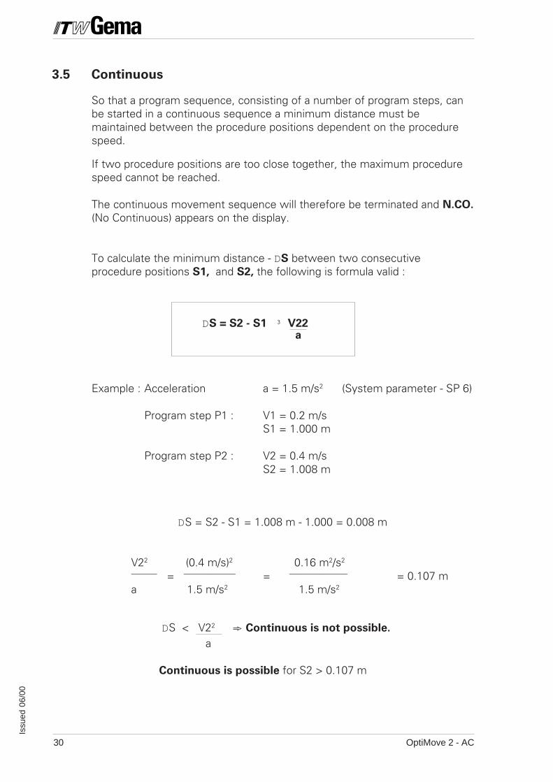
3.5 Continuous
So that a program sequence, consisting of a number of program steps, canbe started in a continuous sequence a minimum distance must bemaintained between the procedure positions dependent on the procedurespeed.
If two procedure positions are too close together, the maximum procedurespeed cannot be reached.
The continuous movement sequence will therefore be terminated and N.CO.
(No Continuous) appears on the display.
To calculate the minimum distance - DS between two consecutiveprocedure positions S1, and S2, the following is formula valid :
Example : Acceleration a = 1.5 m/s2 (System parameter - SP 6)
Program step P1 : V1 = 0.2 m/sS1 = 1.000 m
Program step P2 : V2 = 0.4 m/sS2 = 1.008 m
DS = S2 - S1 = 1.008 m - 1.000 = 0.008 m
V22 (0.4 m/s)2 0.16 m2/s2
———— = ———————— = ————————— = 0.107 ma 1.5 m/s2 1.5 m/s2
DS < V22 => Continuous is not possible.
a
Continuous is possible for S2 > 0.107 m
aDS = S2 - S1 ³ V22
OptiMove 2 - AC 31
Issu
ed 0
6/00
V
t
V2
V3
V1
P1 P2 P3
S1
S2
P1 P2 P3
V2
V3
V1
t
t
S1
S2
S2
S1
V2
V3
V1
P1 P3P2
V
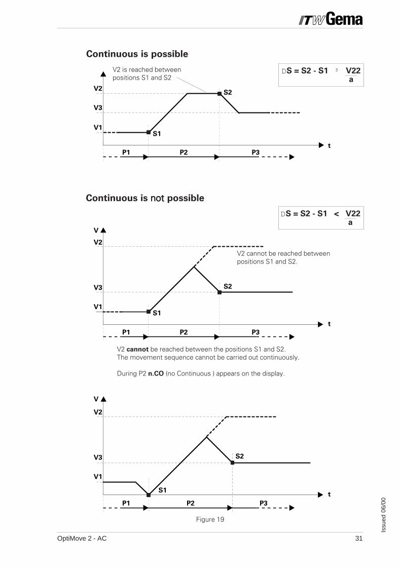
Continuous is not not not not not possible
DS = S2 - S1 ³ V22a
DS = S2 - S1 < V22a
Continuous is possible
V2 is reached betweenpositions S1 and S2
V2 cannot be reached betweenpositions S1 and S2.
V2 cannot be reached between the positions S1 and S2.The movement sequence cannot be carried out continuously.
During P2 n.CO (no Continuous ) appears on the display.
Figure 19
OptiMove 2 - AC32
Issu
ed 0
6/00
4. Automatic operation through an external
control
4.1 Function
The function the OptiMove 2 can be activated by digital control signals froman external control unit.
Switching from manual operation, with the keypad, to automatic controlthrough the digital inputs and outputs by occupying one of these inputs.After successful switching input through the keypad is locked.
The keypad is deactivated,with the exception of error acknowledgementthrough key .
4.2 Switching from Manual to Automatic
Switching between manual, and automatic operation is initiated with thecontrol signal - MAN/AUTO.
MAN/AUTO : High Æ Automatic
MAN/AUTO : Low Æ Manual
OptiMove 2 - AC 33
Issu
ed 0
6/00
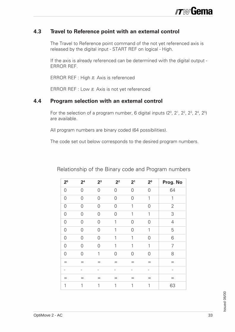
4.3 Travel to Reference point with an external control
The Travel to Reference point command of the not yet referenced axis isreleased by the digital input - START REF on logical - High.
If the axis is already referenced can be determined with the digital output -ERROR REF.
ERROR REF : High Æ Axis is referenced
ERROR REF : Low Æ Axis is not yet referenced
4.4 Program selection with an external control
For the selection of a program number, 6 digital inputs (20, 21, 22, 23, 24, 25)are available.
All program numbers are binary coded (64 possibilities).
The code set out below corresponds to the desired program numbers.
Relationship of the Binary code and Program numbers
25 24 23 22 21 20 Prog. No
0 0 0 0 0 0 64
0 0 0 0 0 1 1
0 0 0 0 1 0 2
0 0 0 0 1 1 3
0 0 0 1 0 0 4
0 0 0 1 0 1 5
0 0 0 1 1 0 6
0 0 0 1 1 1 7
0 0 1 0 0 0 8
= = = = = = =
- - - - - - -
= = = = = = =
1 1 1 1 1 1 63
OptiMove 2 - AC34
Issu
ed 0
6/00
t1 t3
t2
DATEN STABIL
Figure 20
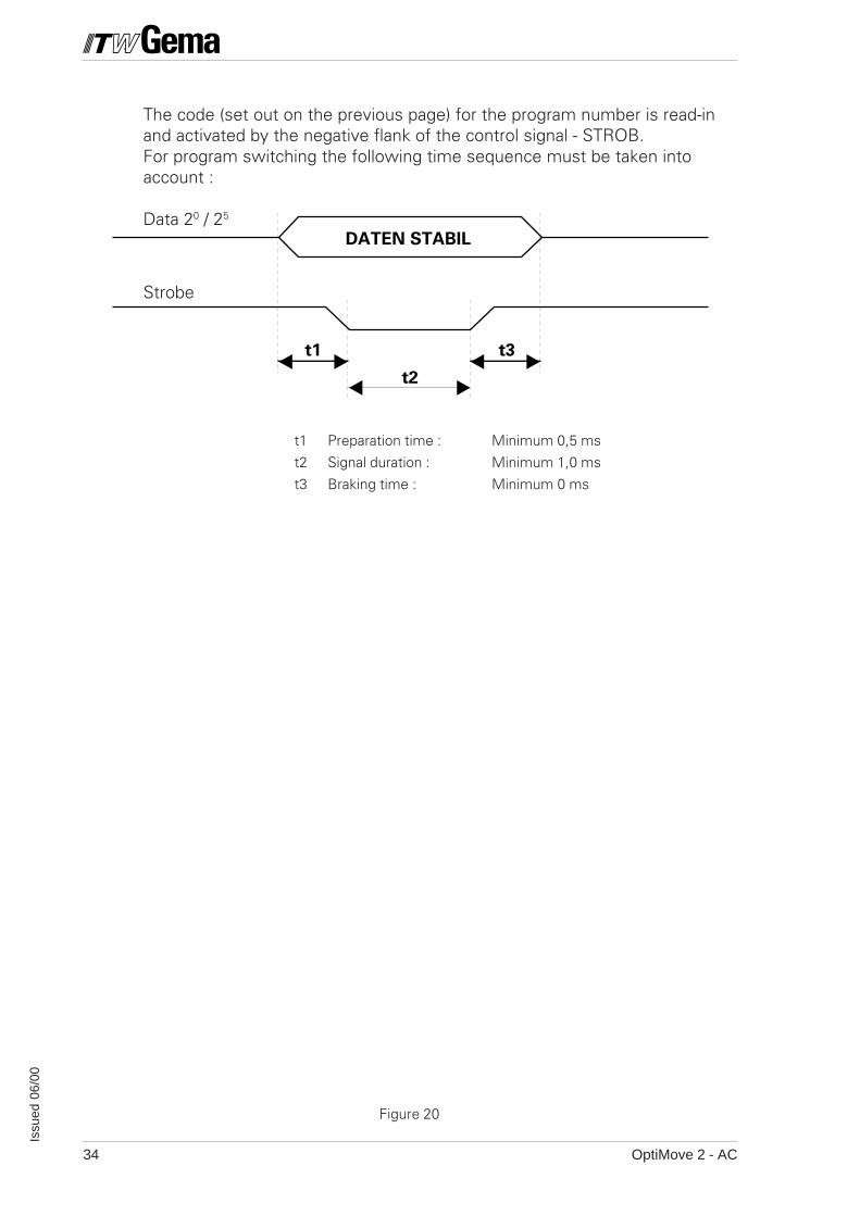
The code (set out on the previous page) for the program number is read-inand activated by the negative flank of the control signal - STROB.For program switching the following time sequence must be taken intoaccount :
Data 20 / 25
Strobe
t1 Preparation time : Minimum 0,5 ms
t2 Signal duration : Minimum 1,0 ms
t3 Braking time : Minimum 0 ms
OptiMove 2 - AC 35
Issu
ed 0
6/00
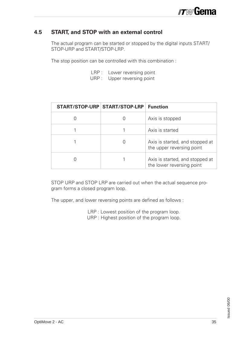
4.5 START, and STOP with an external control
The actual program can be started or stopped by the digital inputs START/STOP-URP and START/STOP-LRP.
The stop position can be controlled with this combination :
LRP : Lower reversing pointURP : Upper reversing point
START/STOP-URP START/STOP-LRP Function
0 0 Axis is stopped
1 1 Axis is started
1 0 Axis is started, and stopped atthe upper reversing point
0 1 Axis is started, and stopped atthe lower reversing point
STOP URP and STOP LRP are carried out when the actual sequence pro-gram forms a closed program loop.
The upper, and lower reversing points are defined as follows :
LRP : Lowest position of the program loop.URP : Highest position of the program loop.
OptiMove 2 - AC36
Issu
ed 0
6/00
4.6 Alarm Input
The motor is disconnected from the power supply by the OptiMove 2Control unit through the digital alarm input - EMERGENCY STOP.This function can be released by the system parameter - SP 8.
EMERGENCY STOP : Low => Axis locked, error message - E09EMERGENCY STOP : High => Normal operation
Important : This input must not not not not not be used as an Emergency Stop for personnel protection as
this function is operated through the electronics (EN 60 20 4) by the software.
4.7 Function output
The digital output - FUNCTION OUT can be set or reset with the procedureprogram.
The switch condition corresponds with the program parameter value - F ofthe active program step.
Program parameter F = O => FUNCTION OUT = HighProgram parameter F = 1 => FUNCTION OUT = Low
4.8 "Program run" signal
If the axis is working through a program can be determined through thedigital output - "PROGRAM RUN".
When a program is started the digital output - PROGRAM RUN is active(High). It remains active as long as the actual program has no furtherfollowing program, and its dwell time has not yet expired.As soon as the last position is reached, and the dwell time has expired theoutput - PROGRAM RUN is inactive (Low).
PROGRAM RUN = Low => - Axis is stopped- Travel to Reference point- Set-up operation
A program is started which does not have a following program or a dwelltime, and the actual axis position is the same as the program position.
PROGRAM RUN = High => - Axis is startedA program is started which does not have a following program, but has adwell time, and the actual axis position is the same as the program position.When the dwell time has expired, the output - PROGRAM RUN is erased.
OptiMove 2 - AC 37
Issu
ed 0
6/00
4.9 Collective error messages
The digital output "GENERAL ERROR" indicates by means of a Low on theoutput that the axis control is in EDIT, SYSTEM PARAMETER or STOPmode. It also gives the following messages :
E08 : EPROM is wrongly "burnt-in" (Check sum error)
E09: EMERGENCY STOP is released
E11: RAM Reset is carried out
E12: Data loss (Check sum error)
E20: Software end stop overrun
E21: Positioning error too great
E24 : Incremental pulse generator errorCable broken - signal A or B, or A and B
E25 : Direction of rotation errorIncremental pulse generator signals A and B reversed
GENERAL ERROR : Low Æ An error exists
GENERAL ERROR : High Æ Normal operation
(See also Chapter 7 - Error messages)
OptiMove 2 - AC38
Issu
ed 0
6/00
CONTROL - INPUT - OUTPUT SYNCHRS - 422
X3 X2POWER IN
X1
X7 SUPPLY
DRIVE POS
X8 CONTROL
1 13
14 26
X4X5X6
C12
R4
C1 C32
A1 A32
R3 C
11
R1
R2
BR
1
R5
C1
C2
C3
C4
C5
C6
C7
C9
C8
C1 C32
A1 A32
C10
OLSTATICVINDUSTRIAL POWDER SYSTEMS
EMAG
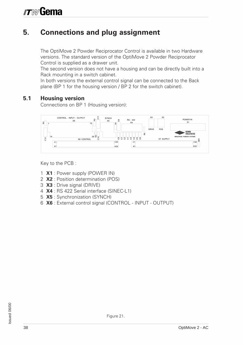
Figure 21.
5. Connections and plug assignment
The OptiMove 2 Powder Reciprocator Control is available in two Hardwareversions. The standard version of the OptiMove 2 Powder ReciprocatorControl is supplied as a drawer unit.The second version does not have a housing and can be directly built into aRack mounting in a switch cabinet.In both versions the external control signal can be connected to the Backplane (BP 1 for the housing version / BP 2 for the switch cabinet).
5.1 Housing versionConnections on BP 1 (Housing version):
Key to the PCB :
1 X1 : Power supply (POWER IN)2 X2 : Position determination (POS)3 X3 : Drive signal (DRIVE)4 X4 : RS 422 Serial interface (SINEC-L1)5 X5 : Synchronization (SYNCH)6 X6 : External control signal (CONTROL - INPUT - OUTPUT)

OptiMove 2 - AC 39
Issu
ed 0
6/00
RS - 422
X1 POWER IN
SUPPLYCONTROL
X4
R4
R5
C11
R1
R2 C8
C8
C10
BP2 V1.0
X9 DISPLAY
POWER ON
2
4
6
8
10
12
14
16
18
20
22
24
26
28
30
32
2
4
6
8
10
12
14
OLSTATICVINDUSTRIAL POWDER SYSTEMS
EMAG
1 2 3 4 5 6 7 8 9 10 11 12 13
14 15 16 17 18 19 20 21 22 23 24 25 26
C3
C4
C2
C1
C5
C6
C7
BR
3B
R2
BR
1
C18
C12
C19
C17
C13
C14
C16
C15
MONTAGEZONE RACK
X2 DRIVE X3 POS
X5 SYNCH
8 7 4 3 2 1
6 4 1
X8 X7a c a c
V1
R3
X6
X2 X3
X9
X1
X5
X4
X6 CONTROL - INPUT - OUTPUT
5.2 Mounting in a switch cabinet
Connections on BP 2 (for the Switch cabinet)
Figure 22.
Control printed circuit board is mounted vertically in the switch cabinet :
X1 : Power supply (POWER IN)X2 : Drive signal (DRIVE)X3 : Position determination (POS)X4 : RS 422 Serial interface (SINEC-L1)X5 : Synchronization (SYNCH)X6 : External control signal
(CONTROL-INPUT-OUTPUT)X9 : Display connections (DISPLAY)
OptiMove 2 - AC40
Issu
ed 0
6/00
1
2
3
4
5
6
7
8
9
10
PE
P
N
Bridge (4-8)
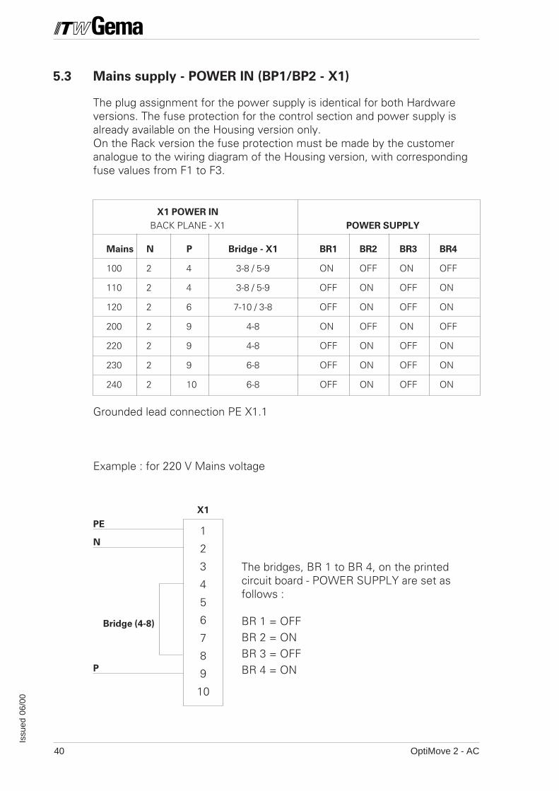
X1
5.3 Mains supply - POWER IN (BP1/BP2 - X1)
The plug assignment for the power supply is identical for both Hardwareversions. The fuse protection for the control section and power supply isalready available on the Housing version only.On the Rack version the fuse protection must be made by the customeranalogue to the wiring diagram of the Housing version, with correspondingfuse values from F1 to F3.
X1 POWER IN
BACK PLANE - X1 POWER SUPPLY
Mains N P Bridge - X1 BR1 BR2 BR3 BR4
100 2 4 3-8 / 5-9 ON OFF ON OFF
110 2 4 3-8 / 5-9 OFF ON OFF ON
120 2 6 7-10 / 3-8 OFF ON OFF ON
200 2 9 4-8 ON OFF ON OFF
220 2 9 4-8 OFF ON OFF ON
230 2 9 6-8 OFF ON OFF ON
240 2 10 6-8 OFF ON OFF ON
Grounded lead connection PE X1.1
Example : for 220 V Mains voltage
The bridges, BR 1 to BR 4, on the printedcircuit board - POWER SUPPLY are set asfollows :
BR 1 = OFFBR 2 = ONBR 3 = OFFBR 4 = ON
OptiMove 2 - AC 41
Issu
ed 0
6/00
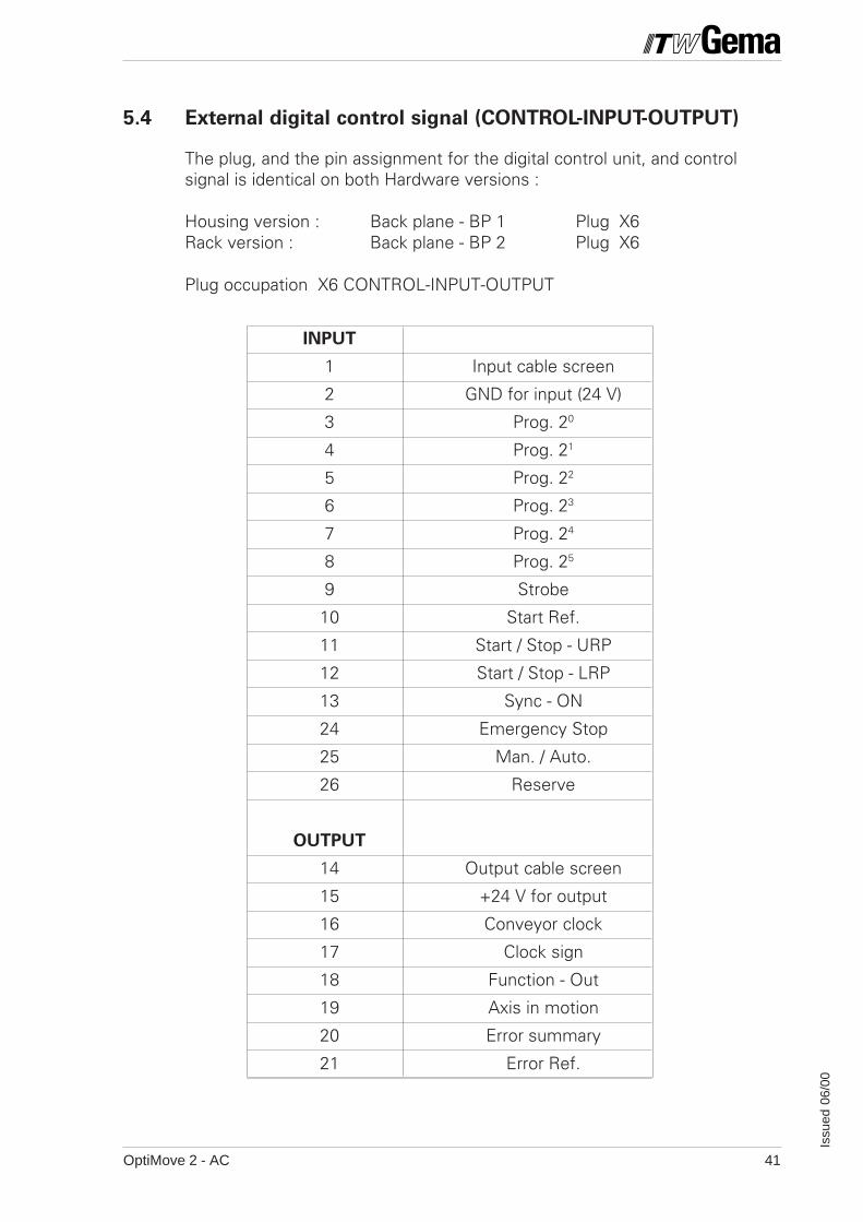
5.4 External digital control signal (CONTROL-INPUT-OUTPUT)
The plug, and the pin assignment for the digital control unit, and controlsignal is identical on both Hardware versions :
Housing version : Back plane - BP 1 Plug X6Rack version : Back plane - BP 2 Plug X6
Plug occupation X6 CONTROL-INPUT-OUTPUT
INPUT
1 Input cable screen
2 GND for input (24 V)
3 Prog. 20
4 Prog. 21
5 Prog. 22
6 Prog. 23
7 Prog. 24
8 Prog. 25
9 Strobe
10 Start Ref.
11 Start / Stop - URP
12 Start / Stop - LRP
13 Sync - ON
24 Emergency Stop
25 Man. / Auto.
26 Reserve
OUTPUT
14 Output cable screen
15 +24 V for output
16 Conveyor clock
17 Clock sign
18 Function - Out
19 Axis in motion
20 Error summary
21 Error Ref.
OptiMove 2 - AC42
Issu
ed 0
6/00
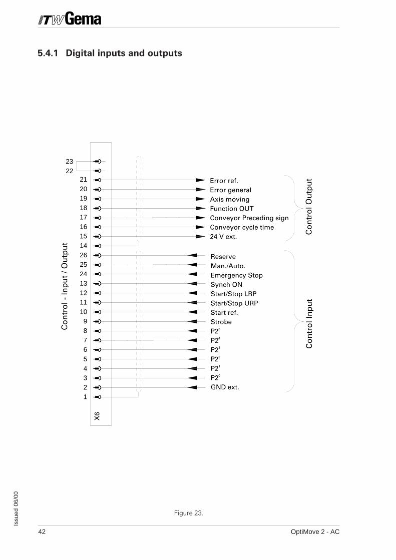
ReserveMan./Auto.Emergency StopSynch ONStart/Stop LRPStart/Stop URPStart ref.StrobeP25
P24
P23
P22
P21
P20
GND ext.
Error ref.Error generalAxis movingFunction OUTConveyor Preceding signConveyor cycle time24 V ext.
Co
ntr
ol -
Inp
ut
/ Ou
tpu
t
Co
ntr
ol I
np
ut
Co
ntr
ol O
utp
ut
X6
212019181716151426252413121110987654321
2322
5.4.1 Digital inputs and outputs
Figure 23.
OptiMove 2 - AC 43
Issu
ed 0
6/00
PRC3
+24 V
+24 V
Uce
K1
GND 24 V
.
.
.
.
* .
.
.
.
.
.
.
.
IL
X6 : 15
X6 : 16
X6 : 21
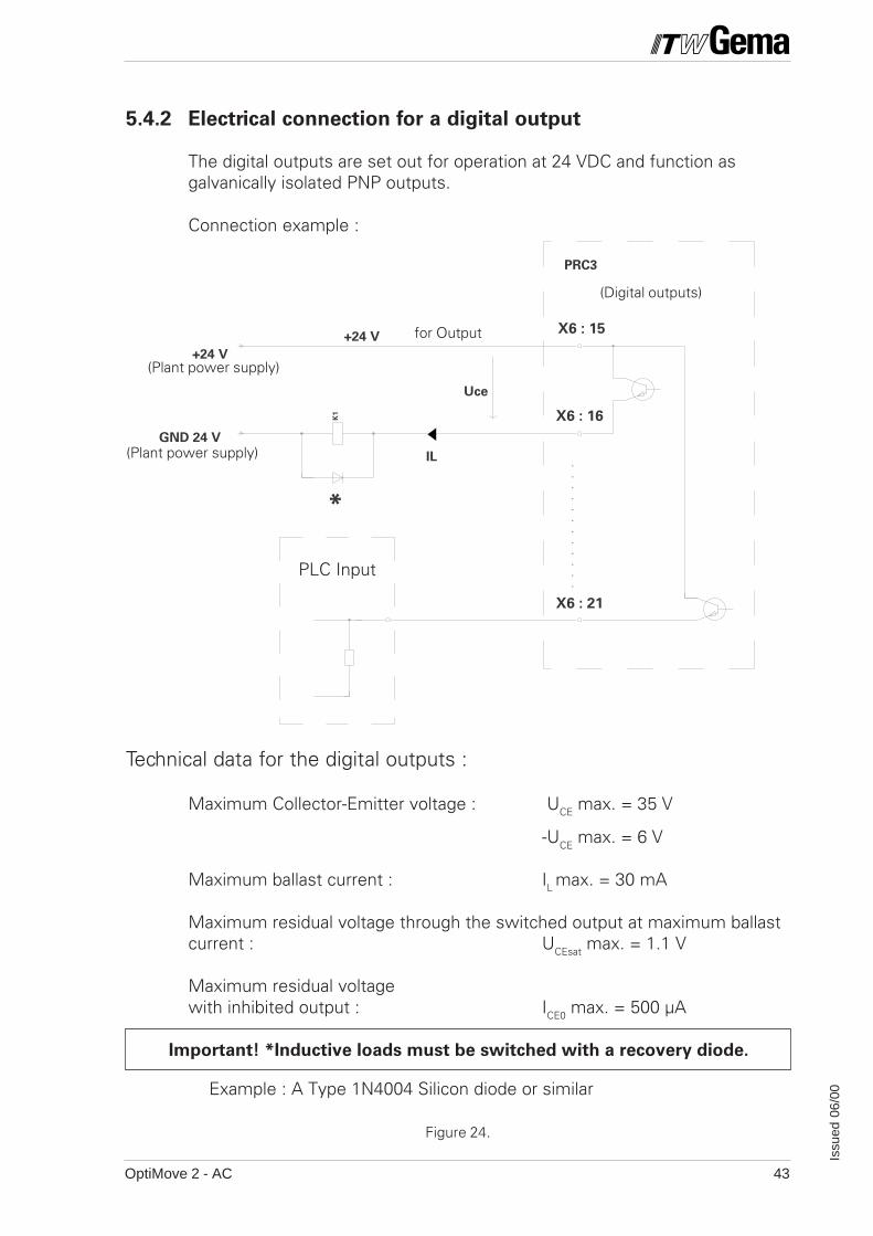
5.4.2 Electrical connection for a digital output
The digital outputs are set out for operation at 24 VDC and function asgalvanically isolated PNP outputs.
Connection example :
Technical data for the digital outputs :
Maximum Collector-Emitter voltage : UCE max. = 35 V
-UCE max. = 6 V
Maximum ballast current : IL max. = 30 mA
Maximum residual voltage through the switched output at maximum ballastcurrent : UCEsat max. = 1.1 V
Maximum residual voltagewith inhibited output : ICE0 max. = 500 µA
Important! *Inductive loads must be switched with a recovery diode.
Example : A Type 1N4004 Silicon diode or similar
PLC Input
Figure 24.
(Digital outputs)
(Plant power supply)
(Plant power supply)
for Output

OptiMove 2 - AC44
Issu
ed 0
6/00
PRC3
+24V
.
.
.
.
.
.
.
.
.
.
24V
GND FOR INPUT
/2.8
X6 : 3
X6 : 26
X6 : 2
(Digital inputs)
e.g. PLC
PLC output
24 V ExternalEquipment powersupply
5.4.3 Electrical connection for a digital input
Technical data of the digital inputs :
Nominal value : 24 VDCFor "0" signal : 0-1.6 V(Negative input voltage, max. -10.0 V)
For "1" signal : 14-30 V(30 V Permanent, max. 35 V for t<100 ms)
Input voltage : Typically 4.8 mA (at 24 V)
Switch or PNP outputto the + 24 V External
GND 24 V ExternalEquipment powersupply
Figure 25.
OptiMove 2 - AC 45
Issu
ed 0
6/00
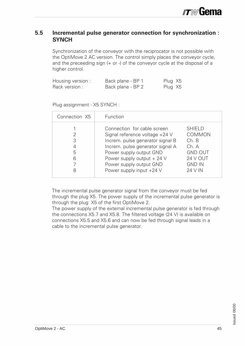
5.5 Incremental pulse generator connection for synchronization :
SYNCH
Synchronization of the conveyor with the reciprocator is not possible withthe OptiMove 2 AC version. The control simply places the conveyor cycle,and the preceeding sign (+ or -) of the conveyor cycle at the disposal of ahigher control.
Housing version : Back plane - BP 1 Plug X5Rack version : Back plane - BP 2 Plug X5
Plug assignment - X5 SYNCH :
Connection X5 Function
1 Connection for cable screen SHIELD2 Signal reference voltage +24 V COMMON3 Increm. pulse generator signal B Ch. B4 Increm. pulse generator signal A Ch. A5 Power supply output GND GND OUT6 Power supply output + 24 V 24 V OUT7 Power supply output GND GND IN8 Power supply input +24 V 24 V IN
The incremental pulse generator signal from the conveyor must be fedthrough the plug X5. The power supply of the incremental pulse generator isthrough the plug X5 of the first OptiMove 2.The power supply of the external incremental pulse generator is fed throughthe connections X5.7 and X5.8. The filtered voltage (24 V) is available onconnections X5.5 and X5.6 and can now be fed through signal leads in acable to the incremental pulse generator.
OptiMove 2 - AC46
Issu
ed 0
6/00
PRC 3
COMMON (+24V)
Ch B
Ch A
GND 24V (X5/7)
X5 : 2
X5 : 3
X5 : 4
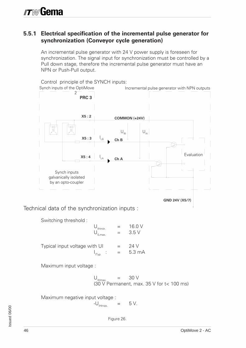
5.5.1 Electrical specification of the incremental pulse generator for
synchronization (Conveyor cycle generation)
An incremental pulse generator with 24 V power supply is foreseen forsynchronization. The signal input for synchronization must be controlled by aPull down stage, therefore the incremental pulse generator must have anNPN or Push-Pull output.
Control principle of the SYNCH inputs:
Technical data of the synchronization inputs :
Switching threshold :UIHmin. = 16.0 VUILmax. = 3.5 V
Typical input voltage with UI = 24 VIITyp : = 5.3 mA
Maximum input voltage :
UIHmax. = 30 V(30 V Permanent, max. 35 V for t< 100 ms)
Maximum negative input voltage :-UIHmax. = 5 V.
Synch inputs of the OptiMove2
Incremental pulse generator with NPN outputs
UIB UIA
ILA
ILB
Synch inputsgalvanically isolatedby an opto-coupler
Evaluation
Figure 26.
OptiMove 2 - AC 47
Issu
ed 0
6/00
2.7
2.6
2.0
2.0
/4.
2
Ch
A
Ch
B
CO
MM
ON
BP1 or BP2
X5
12
34
5
*
6
EMV
FILTER
78
Ch
A
Ch
B
CO
MM
ON
BP1 or BP2
*
X5
1
+24V (COMMON)
2
Ch B
3
Ch A
4
GND
56
+24V
7
GND (24V)8
EMVFILTER
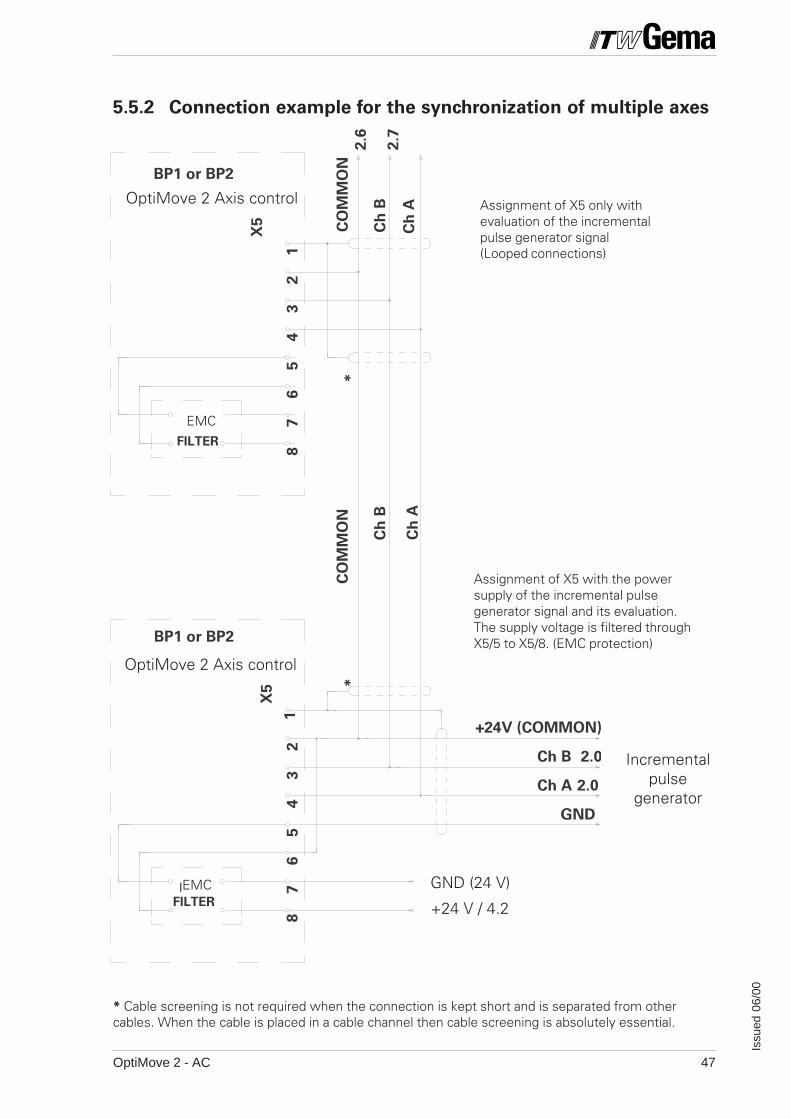
5.5.2 Connection example for the synchronization of multiple axes
Incrementalpulse
generator
Assignment of X5 only withevaluation of the incrementalpulse generator signal(Looped connections)
Assignment of X5 with the powersupply of the incremental pulsegenerator signal and its evaluation.The supply voltage is filtered throughX5/5 to X5/8. (EMC protection)
OptiMove 2 Axis control
OptiMove 2 Axis control
* Cable screening is not required when the connection is kept short and is separated from othercables. When the cable is placed in a cable channel then cable screening is absolutely essential.
+24 V / 4.2
GND (24 V)EMC
EMC
OptiMove 2 - AC48
Issu
ed 0
6/00
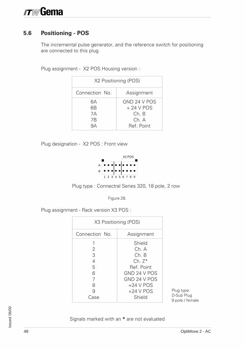
5.6 Positioning - POS
The incremental pulse generator, and the reference switch for positioningare connected to this plug.
Plug assignment - X2 POS Housing version :
X2 Positioning (POS)
Connection No. Assignment
6A GND 24 V POS6B + 24 V POS7A Ch. B7B Ch. A9A Ref. Point
Plug designation - X2 POS : Front view
Plug type : Connectral Series 320, 18 pole, 2 row
Figure 28.
Plug assignment - Rack version X3 POS :
X3 Positioning (POS)
Connection No. Assignment
1 Shield2 Ch. A3 Ch. B4 Ch. Z*5 Ref. Point6 GND 24 V POS7 GND 24 V POS8 +24 V POS9 +24 V POS
Case Shield
A
B
1 2 3 4 65 7 8 9
X2 POS
Signals marked with an * are not evaluated
Plug type:D-Sub Plug9 pole / female
OptiMove 2 - AC 49
Issu
ed 0
6/00
A
B
1 2 3 4 65 7 8 9
X3 DRIVE
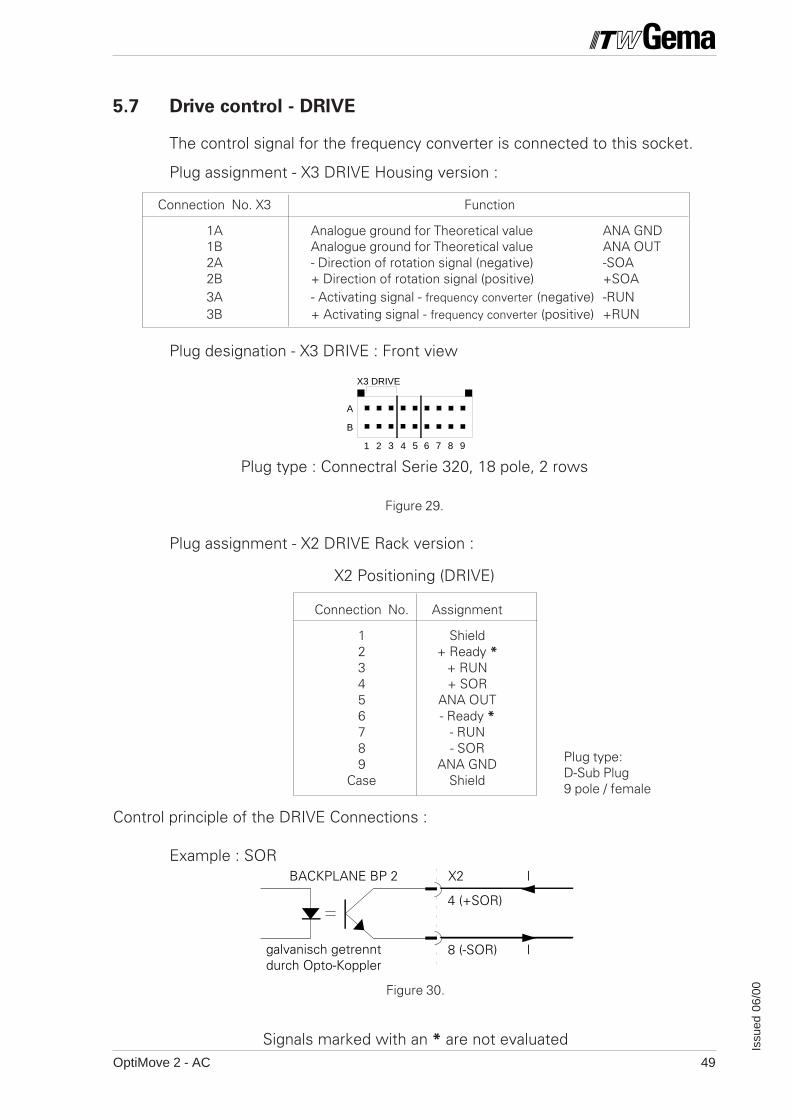
5.7 Drive control - DRIVE
The control signal for the frequency converter is connected to this socket.
Plug assignment - X3 DRIVE Housing version :
Connection No. X3 Function
1A Analogue ground for Theoretical value ANA GND1B Analogue ground for Theoretical value ANA OUT2A - Direction of rotation signal (negative) -SOA2B + Direction of rotation signal (positive) +SOA3A - Activating signal - frequency converter (negative) -RUN3B + Activating signal - frequency converter (positive) +RUN
Plug designation - X3 DRIVE : Front view
Plug type : Connectral Serie 320, 18 pole, 2 rows
Figure 29.
Plug assignment - X2 DRIVE Rack version :
X2 Positioning (DRIVE)
Connection No. Assignment
1 Shield2 + Ready *3 + RUN4 + SOR5 ANA OUT6 - Ready *7 - RUN8 - SOR9 ANA GND
Case Shield
Control principle of the DRIVE Connections :
Example : SOR
Plug type:D-Sub Plug9 pole / female
Figure 30.
Signals marked with an * are not evaluated
galvanisch getrenntdurch Opto-Koppler
BACKPLANE BP 2 X2 I
I8 (-SOR)
4 (+SOR)
OptiMove 2 - AC50
Issu
ed 0
6/00
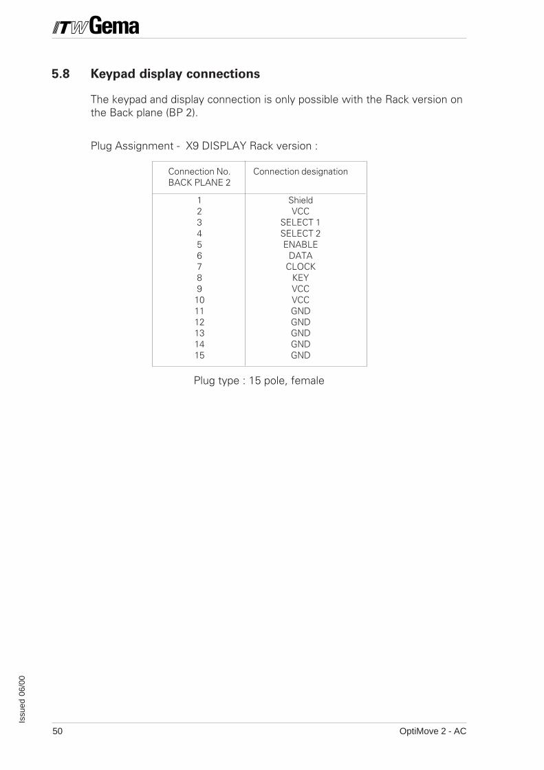
5.8 Keypad display connections
The keypad and display connection is only possible with the Rack version onthe Back plane (BP 2).
Plug Assignment - X9 DISPLAY Rack version :
Connection No. Connection designationBACK PLANE 2
1 Shield2 VCC3 SELECT 14 SELECT 25 ENABLE6 DATA7 CLOCK8 KEY9 VCC10 VCC11 GND12 GND13 GND14 GND15 GND
Plug type : 15 pole, female
OptiMove 2 - AC 51
Issu
ed 0
6/00
PRC 3Externalcontrol,e.g. PLC
Direction of synchronization
Direction of travel
Incremental pulse generator
Conveyor cycle : Position of the conveyor chain
Axiswith DCMotor
General control signal
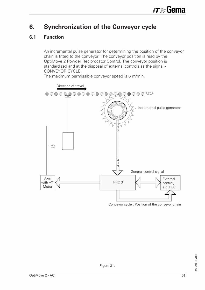
6. Synchronization of the Conveyor cycle
6.1 Function
An incremental pulse generator for determining the position of the conveyorchain is fitted to the conveyor. The conveyor position is read by theOptiMove 2 Powder Reciprocator Control. The conveyor position isstandardized and at the disposal of external controls as the signal -CONVEYOR CYCLE.The maximum permissible conveyor speed is 6 m/min.
Figure 31.
AC
OptiMove 2 - AC52
Issu
ed 0
6/00
4
3 2 5 1
Figure 32.
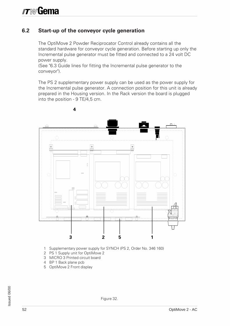
6.2 Start-up of the conveyor cycle generation
The OptiMove 2 Powder Reciprocator Control already contains all thestandard hardware for conveyor cycle generation. Before starting up only theIncremental pulse generator must be fitted and connected to a 24 volt DCpower supply.(See "6.3 Guide lines for fitting the Incremental pulse generator to theconveyor").
The PS 2 supplementary power supply can be used as the power supply forthe Incremental pulse generator. A connection position for this unit is alreadyprepared in the Housing version. In the Rack version the board is pluggedinto the position - 9 TE/4,5 cm.
1 Supplementary power supply for SYNCH (PS 2, Order No. 346 160)2 PS 1 Supply unit for OptiMove 23 MICRO 3 Printed circuit board4 BP 1 Back plane pcb5 OptiMove 2 Front display
OptiMove 2 - AC 53
Issu
ed 0
6/00
10 89 7 6 5 4 3 2 132 28
c
a/b
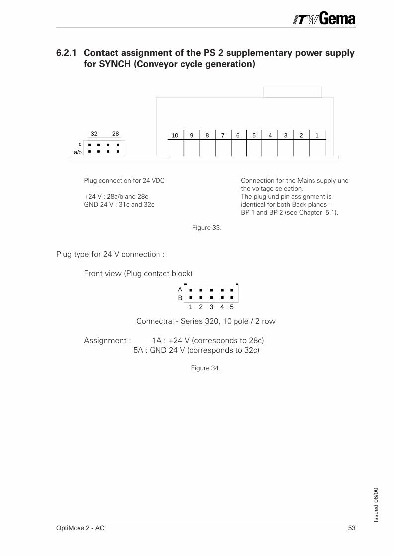
6.2.1 Contact assignment of the PS 2 supplementary power supply
for SYNCH (Conveyor cycle generation)
Plug type for 24 V connection :
Front view (Plug contact block)
Connectral - Series 320, 10 pole / 2 row
Assignment : 1A : +24 V (corresponds to 28c) 5A : GND 24 V (corresponds to 32c)
A
B1 2 3 4 5
Figure 33.
Figure 34.
Plug connection for 24 VDC
+24 V : 28a/b and 28cGND 24 V : 31c and 32c
Connection for the Mains supply undthe voltage selection.The plug und pin assignment isidentical for both Back planes -BP 1 and BP 2 (see Chapter 5.1).
OptiMove 2 - AC54
Issu
ed 0
6/00
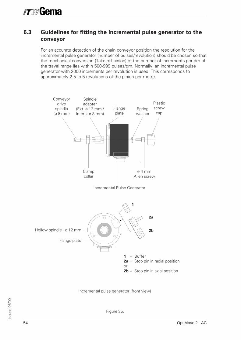
6.3 Guidelines for fitting the incremental pulse generator to the
conveyor
For an accurate detection of the chain conveyor position the resolution for theincremental pulse generator (number of pulses/revolution) should be chosen so thatthe mechanical conversion (Take-off pinion) of the number of increments per dm ofthe travel range lies within 500-999 pulses/dm. Normally, an incremental pulsegenerator with 2000 increments per revolution is used. This corresponds toapproximately 2.5 to 5 revolutions of the pinion per metre.
ø 4 mmAllen screw
Clampcollar
Flangeplate
Plasticscrew
capSpringwasher
Conveyordrive
spindle(ø 8 mm)
Spindleadapter
(Ext. ø 12 mm /Intern. ø 8 mm)
Incremental Pulse Generator
2a
1
Flange plate
Hollow spindle - ø 12 mm
Incremental pulse generator (front view)
1 = Buffer2a = Stop pin in radial positionor2b = Stop pin in axial position
Figure 35.
2b

OptiMove 2 - AC 55
Issu
ed 0
6/00
6.3.1 Instructions for fitting the incremental pulse generator
The incremental pulse generator is supplied by GEMA.In order to guarantee trouble-free operation of the incremental pulse generator, andthe whole powder coating booth the following points must be observed thoroughly:
- never fit the incremental pulse generator to the motor spindle, but only onthe drive spindle of the conveyor
- fit the incremental pulse generator as close to the booth entrance aspossible.
- if the incremental pulse generator is fitted with a slipping clutch, fit theincremental pulse generator so that when the chain is stopped because ofoverloading, the incremental pulse generator must also stop.
The incremental pulse generator is fitted either directly onto the drive spindle of theconveyor or with the aid of a spindle adapter (see Fig. 36). If the drive spindle is notø 8 mm, then a suitable spindle adapter can be ordered.
Fig. 36a
ATTENTION: Never fit the incremental pulse generator on an additional fixture supplied by
the customer (flange or similar) when the generator is fitted to the drive
spindle, even when the spindle is perfectly aligned.
If the incremental pulse generator is fitted in a different manner to the
above mentioned method, always consult a GEMA service centre first.
The rotation of the incremental pulse generator with the drive spindle is stopped bya buffer (1) or a stop pin (2), which fits onto the fixing flange (supplied by thecustomer) and into the specially made cut-out in the incremental pulse generatorflange plate. It is recommended to stick the torque buffer/stop pin to the flangeplate of the incremental pulse generator with commercially available Cyan acrylicadhesive (Sicomet 50 or Loctite 406). The stop pin can be fitted radially (2a) oraxially (2b) depending on how the fixing flange is made.
The electrical connection to the incremental pulse generator is made with the plugsupplied (Fig. 36a)
nötigesSpiel >
necessary play >
Fig. 36
Plug : Type 10 42 36 / IP 64 / Straight type for 5 x 0.34 mm2 cable
OptiMove 2 - AC56
Issu
ed 0
6/00
Pinion fitted with Incremental pulse generator
Conveyor chain
Observed length
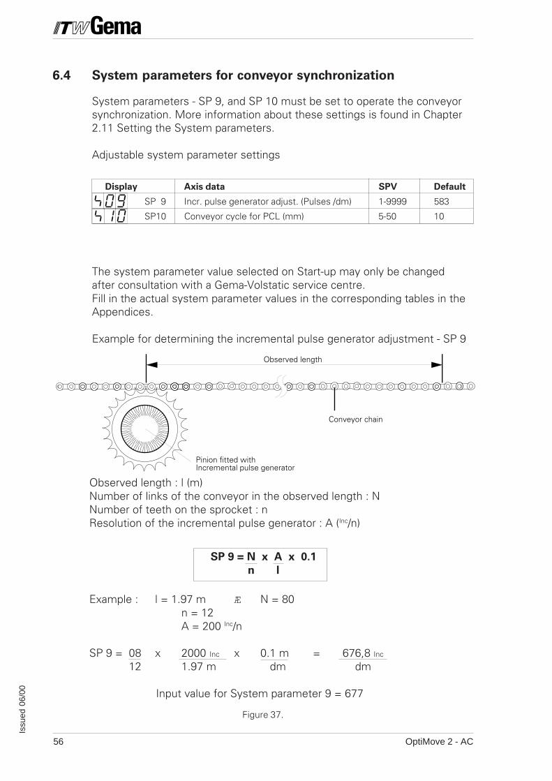
Display Axis data SPV Default
SP 9 Incr. pulse generator adjust. (Pulses /dm) 1-9999 583
SP10 Conveyor cycle for PCL (mm) 5-50 10
The system parameter value selected on Start-up may only be changedafter consultation with a Gema-Volstatic service centre.Fill in the actual system parameter values in the corresponding tables in theAppendices.
Example for determining the incremental pulse generator adjustment - SP 9
Figure 37.
Observed length : l (m)Number of links of the conveyor in the observed length : NNumber of teeth on the sprocket : nResolution of the incremental pulse generator : A (Inc/n)
SP 9 = N x A x 0.1
n l
Example : l = 1.97 m Æ N = 80n = 12A = 200 Inc/n
SP 9 = 08 x 2000 Inc x 0.1 m = 676,8 Inc
12 1.97 m dm dm
Input value for System parameter 9 = 677
6.4 System parameters for conveyor synchronization
System parameters - SP 9, and SP 10 must be set to operate the conveyorsynchronization. More information about these settings is found in Chapter2.11 Setting the System parameters.
Adjustable system parameter settings
OptiMove 2 - AC 57
Issu
ed 0
6/00
6.6 Digital control signals for conveyor
synchronization
6.6.1 Conveyor cycle outputs
The OptiMove 2 provides two digital signal outputs for the sequence controlto determine the conveyor position.
These are :
CONVEYOR CLOCK : Conveyor cycle in mm(Resolution by SP 10)
CLOCK SIGN : Preceding sign (+ or -) of the conveyor cycle
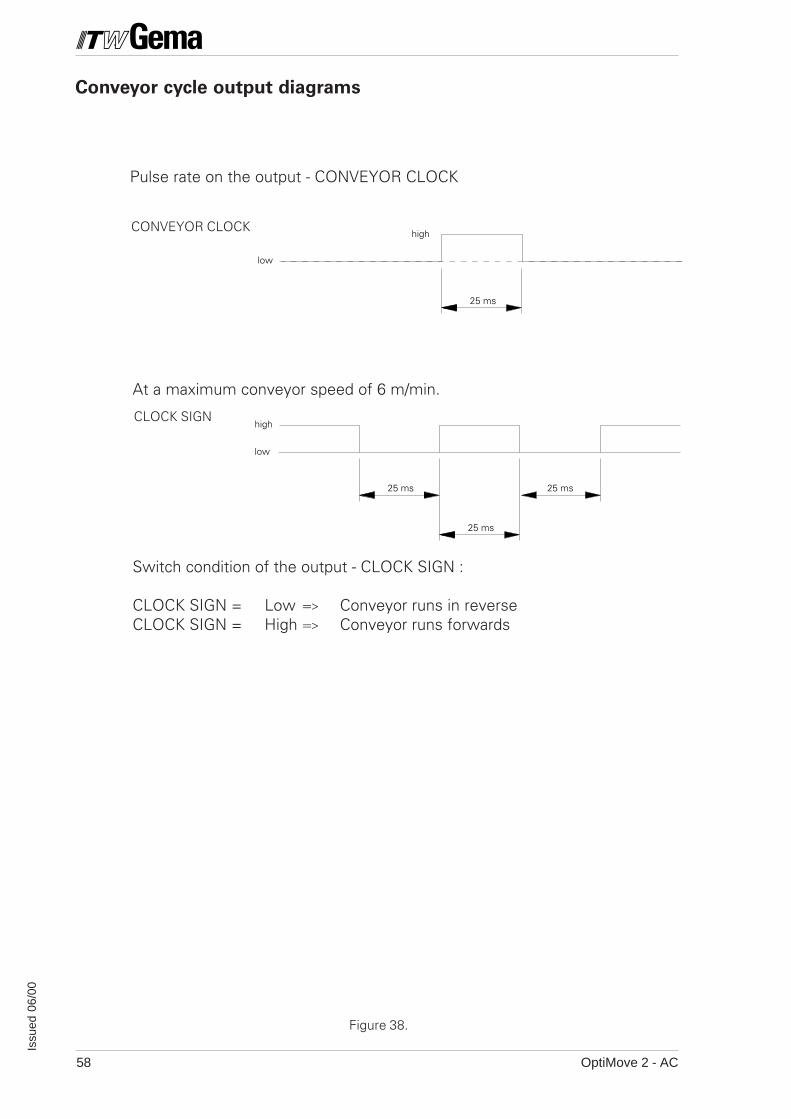
A high pulse, with a constant pulse length of 25 ms, is given over apredetermined distance by the system parameter - SP 10 on the output -CONVEYOR CLOCK. The direction of travel can be determined through theoutput - CLOCK SIGN.
The system can accomodate a maximum conveyor speed of 6 m/min.
OptiMove 2 - AC58
Issu
ed 0
6/00
25 ms
high
low
high
low
25 ms 25 ms
25 ms
Figure 38.
Pulse rate on the output - CONVEYOR CLOCK
Switch condition of the output - CLOCK SIGN :
CLOCK SIGN = Low => Conveyor runs in reverseCLOCK SIGN = High => Conveyor runs forwards
CLOCK SIGN
CONVEYOR CLOCK
Conveyor cycle output diagrams
At a maximum conveyor speed of 6 m/min.
OptiMove 2 - AC 59
Issu
ed 0
6/00
7. Error messages
E01: Incorrect keyThe error message - "E01E01E01E01E01" appears as soon as an incorrect key is pressed.This can happen when the keypad is locked or when a key is pressed in aprogram level where this is not permitted.The "E01E01E01E01E01" message appears on the display for as long as the incorrect keyis pressed.
Acknowledgement is not necessary.
E08 : The error message "E08" appears when the Check Sum in the EPROM doesnot correspond with the actual Check Sum of the operating program.
Acknowledgement : None.
Source of error : EPROM incorrectly "burnt-in".
Course of action : Replace with a new EPROM.
E9 External alarm input is activated / axis locked by digital control input -"EMERGENCY STOP".
Acknowledgement : Not necessary.
Source of error : EMERGENCY STOP is approached (Low).EMERGENCY STOP is activated by the Systemparameter - SP 8.
E10 : Reference point not reachedWhen switching on the axis control "E10" appears on the display.This message means that the position of the Reference point has not yetbeen stored. By pressing the key the Travel to Reference point can bereleased. The Travel to Reference point can also be released digitallythrough the digital input - "Travel to Reference point".
Acknowledgement : Travel to Reference point with the key in manualoperation. In automatic operation the control input"START REF" must be approached.
E11: RAM Reset is carried out.This message appears when a RAM Reset is carried out .
Acknowledgement : by up-dating the system parameter(See Chapter 2.11)
OptiMove 2 - AC60
Issu
ed 0
6/00
E12: System parameter (SP) not set.This error message appears when the Check Sum is incorrect for all thesystem parameters. When there is a Check Sum error the SPV (SystemParameter Values) are loaded with default values.
Acknowledgement : by pressing the key a RAM Reset is carried outand the error message - "E11" appears on thedisplay.
Source of error : Replacement of the RAM moduleData loss in RAM
E20: Software end stop is overrun (Synchronization).This error message appears when the actual position of the axis is greaterthan the defined software end stop (Software end stop = Upper strokelimit + 10 mm). This error can only happen in the synchronizationoperation.
Acknowledgement : by pressing the key
Source of error : The travel distance of the axis when synchronizinglies outside the maximum permissible travel
distance (SP 1, SP 2).
E21: Positioning error too large.
Acknowledgement : by pressing the key
Source of error : No signal from incremental pulse generator.Axis has run into the end buffer (SP1 incorrectly set )No theoretical value (ANA, GND, ANA OUT) for thefrequency generator
E22: Incremental pulse generator error
Acknowledgement : by pressing the key
Source of error : Incremental pulse generator is incorrectly connectedor not connected at all.
E24 : This error message appears when there is an incremental pulse generatorerror. (Cable break signals A or B, or A and B)
Acknowledgement : by pressing the key .
Source of error : No incremental pulse generator signals.
OptiMove 2 - AC 61
Issu
ed 0
6/00
E25 : This error message appears when the direction of rotation of the positioningdetection is reversed.
Acknowledgement : by pressing the key .
Source of error : Incremental pulse generator signals A and Bare reversed.
END : No further program step.When in the program level - STEP the next STEP should be released withthe key , and no further STEP (program step) is present, the errormessage "ENDENDENDENDEND" appears until the appropriate key is released.
n.Co : No "Continuous" .

OptiMove 2 - AC62
Issu
ed 0
6/00
Notes :
1OptiMove 2 - AC
Issu
ed 0
6/00
Appendix A
Spare Parts List
Ordering Spare Parts
When ordering spare parts for powder coating equipment, please indicatethe following specifications :
1. Type, and serial number of your powder coating equipment
2. Order number, quantity, and description of each spare part.
Example :
1. Type OptiMove 2, Serial no. : xxx xxx
2. Order no. : 227 161, 5 pieces, Fine wire fuse.
When ordering cable and hose material the length required must alsobe given.The spare part numbers metre/yard ware is always marked with an *.
All wear parts are marked with a #.
All dimension of plastic powder hoses are given with external and internaldiameters :e.g.ø 8 / 6 mm = 8 mm outside diameter (o/d)/ 6 mm inside diameter (i/d).

2 OptiMove 2 - AC
Issu
ed 0
6/00
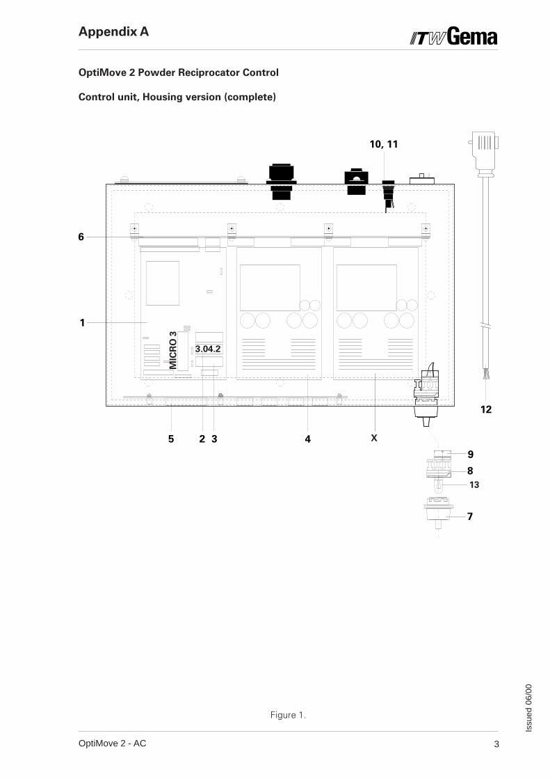
OptiMove 2 Powder Reciprocator Control
Control unit, Housing version (complete)
1 Control board - Micro 3 (PBC) 344 2572 EPROM 3.XX.2 - AC 349 3213 512 kB RAM for program memory 240 9744 PS 1 Power supply (PBC) 340 3835 Front display for OptiMove 2 342 9046 BP 1 Back plane (PBC) 342 7857 Main switch 235 9118 Lamp element 235 9209 Contact element 235 938
10 Fuse holder 200 13111 Fuse - 0.25 AT - 200-240 V 227 161#
Fuse - 5.0 AT - 200 -240 V 200 166#Fuse - 0.5 AT - 100 - 120 V 201 073#Fuse - 10AT - 100 - 120 V 200 174#
12 Cable with plug 303 60713 Bulb -130 V / 20 mA 203 688#
X PS 2 Power supply board (PBC) 346 160(Incremental pulse generator supply for Synchro)
Appendix A
# Wear Parts
3OptiMove 2 - AC
Issu
ed 0
6/00
Figure 1.
Appendix A
OptiMove 2 Powder Reciprocator Control
Control unit, Housing version (complete)
MIC
RO
3
X
13
3.04.2
12
9
7
8
1
2 3 45
6
10, 11
4 OptiMove 2 - AC
Issu
ed 0
6/00
OptiMove 2 Powder Reciprocator Control
Rack version - BP 2 Back plane
1 BP 2 Back plane (PBC - Mounted in a Switch cabinet) 347 19113 Micro 3 Control board (PBC) for OptiMove 2 344 25714 PS 1 Power supply board (PBC) for OptiMove 2 340 383
PS 2 Power supply board (PBC) 346 160Mounting frame for display print 349 186
Appendix A
5OptiMove 2 - AC
Issu
ed 0
6/00
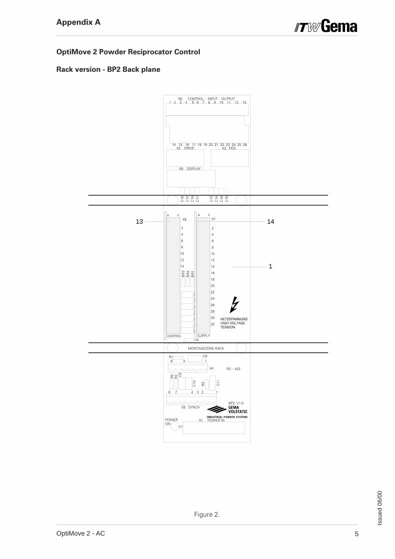
OptiMove 2 Powder Reciprocator Control
Rack version - BP2 Back plane
Figure 2.
RS - 422
X1 POWER IN
SUPPLYCONTROL
X4
R4
R5
C11
R1
R2 C8
C8
C10
BP2 V1.0
X9 DISPLAY
POWER ON
2
4
6
8
10
12
14
16
18
20
22
24
26
28
30
32
2
4
6
8
10
12
14
OLSTATICVINDUSTRIAL POWDER SYSTEMS
EMAG
1 2 3 4 5 6 7 8 9 10 11 12 13
14 15 16 17 18 19 20 21 22 23 24 25 26
C3
C4
C2
C1
C5
C6
C7
BR
3B
R2
BR
1
C18
C12
C19
C17
C13
C14
C16
C15
MONTAGEZONE RACK
X2 DRIVE X3 POS
X5 SYNCH
8 7 4 3 2 1
6 4 1
X8 X7a c a c
V1
R3
13 14
1
X6 CONTROL - INPUT - OUTPUT
Appendix A
6 OptiMove 2 - AC
Issu
ed 0
6/00
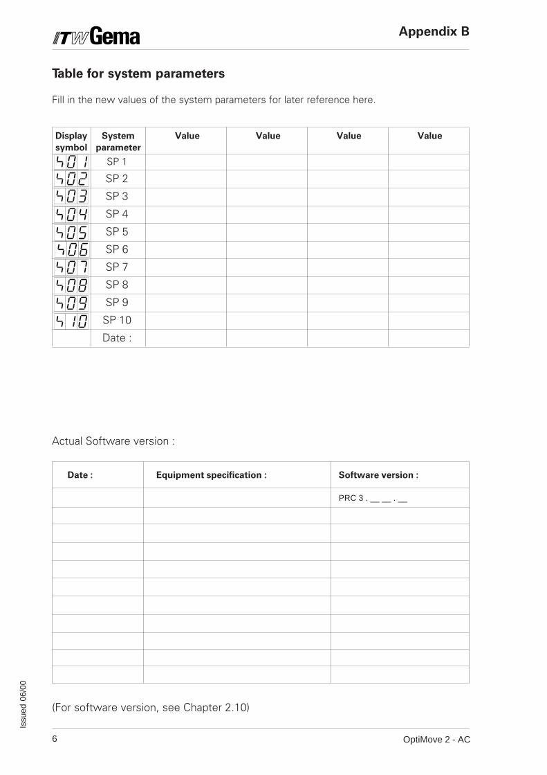
Table for system parameters
Fill in the new values of the system parameters for later reference here.
Display System Value Value Value Value
symbol parameter
SP 1
SP 2
SP 3
SP 4
SP 5
SP 6
SP 7
SP 8
SP 9
SP 10
Date :
Actual Software version :
Date : Equipment specification : Software version :
(For software version, see Chapter 2.10)
Appendix B
PRC 3 . __ __ . __
7OptiMove 2 - AC
Issu
ed 0
6/00
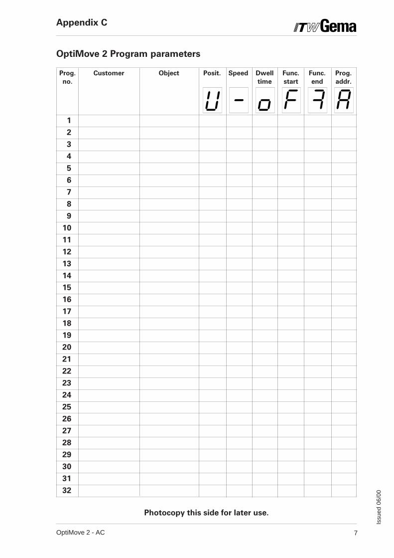
OptiMove 2 Program parameters
Prog. Customer Object Posit. Speed Dwell Func. Func. Prog.
no. time start end addr.
1
2
3
4
5
6
7
8
9
10
11
12
13
14
15
16
17
18
19
20
21
22
23
24
25
26
27
28
29
30
31
32
Photocopy this side for later use.
Appendix C
8 OptiMove 2 - AC
Issu
ed 0
6/00
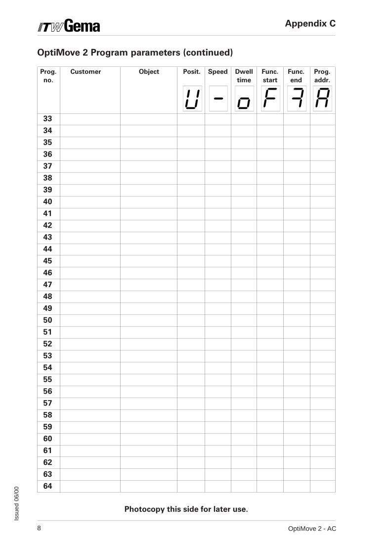
Photocopy this side for later use.
OptiMove 2 Program parameters (continued)
Prog. Customer Object Posit. Speed Dwell Func. Func. Prog.
no. time start end addr.
33
34
35
36
37
38
39
40
41
42
43
44
45
46
47
48
49
50
51
52
53
54
55
56
57
58
59
60
61
62
63
64
Appendix C
9OptiMove 2 - AC
Issu
ed 0
6/00
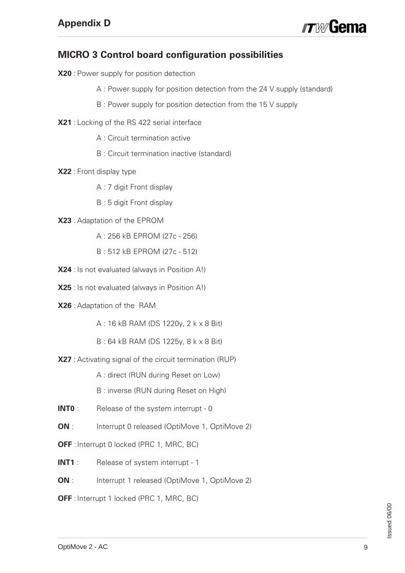
MICRO 3 Control board configuration possibilities
X20 : Power supply for position detection
A : Power supply for position detection from the 24 V supply (standard)
B : Power supply for position detection from the 15 V supply
X21 : Locking of the RS 422 serial interface
A : Circuit termination active
B : Circuit termination inactive (standard)
X22 : Front display type
A : 7 digit Front display
B : 5 digit Front display
X23 : Adaptation of the EPROM
A : 256 kB EPROM (27c - 256)
B : 512 kB EPROM (27c - 512)
X24 : Is not evaluated (always in Position A!)
X25 : Is not evaluated (always in Position A!)
X26 : Adaptation of the RAM
A : 16 kB RAM (DS 1220y, 2 k x 8 Bit)
B : 64 kB RAM (DS 1225y, 8 k x 8 Bit)
X27 : Activating signal of the circuit termination (RUP)
A : direct (RUN during Reset on Low)
B : inverse (RUN during Reset on High)
INT0 : Release of the system interrupt - 0
ON : Interrupt 0 released (OptiMove 1, OptiMove 2)
OFF : Interrupt 0 locked (PRC 1, MRC, BC)
INT1 : Release of system interrupt - 1
ON : Interrupt 1 released (OptiMove 1, OptiMove 2)
OFF : Interrupt 1 locked (PRC 1, MRC, BC)
Appendix D
10 OptiMove 2 - AC
Issu
ed 0
6/00
Documentation OptiMove 2 - AC
© Copyright 2000 ITW Gema AG, CH-9015 St.Gall.All technical products from ITW Gema AG are constantly being developed basedon our continuing research and applications. The data found in this publication maytherefore be changed without prior notification.
Printed in Switzerland
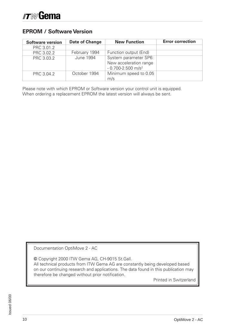
Software version
PRC 3.01.2PRC 3.02.2PRC 3.03.2
PRC 3.04.2
Date of Change
February 1994June 1994
October 1994
New Function
Function output (End)System parameter SP6:New acceleration range- 0.700-2.500 m/s2
Minimum speed to 0.05m/s
Error correction
EPROM / Software Version
Please note with which EPROM or Software version your control unit is equipped.When ordering a replacement EPROM the latest version will always be sent.