optimizing the storage and retrieval efficiency of a solid ... · optimizing the storage and...
TRANSCRIPT
Optimizing the storage and retrieval efficiency of a solid-state
quantum memory through tailored state preparation
Matthew D. Eisamana, Sergey Polyakova,b, Michael Hohenseec, Jingyun Fana,b, Philip
Hemmerd, and Alan Migdalla,b
aOptical Technology Division, National Institute of Standards and Technology, 100 Bureau
Drive, Mail Stop 8441, Gaithersburg, MD 20899-8441, USA;bJoint Quantum Institute, National Institute of Standards and Technology, and University of
Maryland, Department of Physics, University of Maryland, College Park, MD 20742, USA;cPhysics Department, Harvard University, 17 Oxford St., Cambridge, MA 02138, USA;
dDepartment of Electrical and Computer Engineering, Texas A&M University, 214 Zachry
Engineering Center, College Station, Texas 77843-3128, USA
ABSTRACT
We theoretically investigate the feasibility of using spectral hole burning in Pr3+:Y2SiO5 to prepare an ensembleof Pr3+ ions with a spectral distribution optimized for use as a quantum memory for single-photon states. Weintroduce figures of merit for the spectral distribution of the Pr3+ ions when used as a quantum-memory nodein a Duan-Lukin-Cirac-Zoller-type quantum-repeater scheme. Finally, we describe progress toward optimizingthe hole-burning sequence by using a computational model of the hole-burning process to calculate these figuresof merit over a wide range of parameters.
Keywords: quantum memory, quantum repeater, rare-earth ion-doped crystal
1. INTRODUCTION
All realistic schemes for quantum communication are currently based on the use of photonic channels. How-ever, long-distance communication is hampered by the optical loss that increases exponentially with distance,drastically reducing the communication rate. Quantum repeaters, first introduced in 1998,1 can overcome theexponential increase of optical loss with distance by dividing the communication channel into many segments,generating and purifying entanglement for each section individually, and then extending this entanglement overlonger distances via entanglement swapping. Due to the probabilistic nature of purification protocols, efficientimplementation of a quantum repeater requires quantum memory. The requirement of quantum memory sug-gests that we need to store the local qubits in matter-based internal states instead of photonic states, because itis difficult to store photons for long times.
Rare-earth ion-doped crystals are promising candidates for use as a quantum memory for photon states dueto the long ground-state coherence times of the ionic ensembles. Recent experiments using Pr3+-doped Y2SiO5
(Pr3+:Y2SiO5) have demonstrated decoherence times of tens of seconds,2, 3 and storage and retrieval of classicaloptical pulses using electromagnetically induced transparency (EIT) with storage times up to 10 s.4 These timesare 4 orders of magnitude longer than EIT storage times demonstrated for classical optical pulses in atomicgases,5, 6 and 6 orders of magnitude longer than the quantum state storage times demonstrated thus far inatomic gases.7–9
Due to the large inhomogeneous broadening in rare-earth ion-doped crystals (10 GHz for Pr3+:Y2SiO510),
preparation of the initial state of the ionic ensemble is required to isolate a spectral subpopulation with similartransition frequencies. State preparation in these systems is typically accomplished via spectral hole-burningtechniques,10, 11 in which a spectral subpopulation of ions in a specific hyperfine ground state is isolated by first
Further author information: (Send correspondence to M.D.E.)M.D.E.: E-mail: [email protected]
Invited Paper
Quantum Communications Realized edited by Yasuhiko Arakawa, Masahide Sasaki, Hideyuki Sotobayashi,
Proc. of SPIE Vol. 6780, 67800K, (2007) · 0277-786X/07/$18 · doi: 10.1117/12.733951
Proc. of SPIE Vol. 6780 67800K-1

optically pumping a large spectral width (5 MHz -10 MHz) of ions to other ground states (hole-burning), andthen pumping back a narrow (100 kHz-1 MHz) inhomogeneously broadened spectral distribution (an anti-hole)into the desired hyperfine state.
We are interested in the practical aspects of using Pr3+:Y2SiO5 as a quantum memory for photon states,with a special interest in optimization for use in specific quantum-repeater protocols, such as the Duan-Lukin-Cirac-Zoller (DLCZ) scheme.12 In our contribution, we theoretically investigate the feasibility of using spectralhole burning in Pr3+:Y2SiO5 to prepare an ensemble of Pr3+ ions with a spectral distribution optimized for useas a quantum memory for single-photon states. Our work considers a recent theoretical investigation into theimportance of the inhomogeneously broadened spectral lineshape of an ensemble to the storage and retrievalefficiency.13 In Sec. 1.1, we give a brief introduction to the DLCZ quantum-repeater scheme. In Sec. 1.2, wediscuss the details of how Pr3+:Y2SiO5 can be used as a quantum-memory node in the DLCZ scheme, includinga discussion of the required state preparation. In Sec. 2, we describe the details of the calculation used to modelthe hole-burning process. Finally, in Sec. 3 we describe the results of using this model to find the optimum hole-burning sequence to produce the desired spectral distribution. Specifically, we introduce figures of merit for thespectral distribution of the Pr3+ ions when used as a quantum memory node in a DLCZ-type quantum-repeaterscheme, and we optimize the hole-burning sequence by using a computational model of the spectral hole burningprocess to calculate these figures of merit over a wide range of parameters.
1.1 DLCZ Quantum-Repeater Scheme
An important conceptual step toward the realization of quantum repeaters was made in 2001, with the DLCZproposal for long-distance quantum communication using atomic ensembles and linear optics.12 Figure 1(a)illustrates how spontaneous photon scattering from an ensemble of atoms, combined with conditional quantummeasurement, can be used to implement the backbone of this protocol - the probabilistic generation of quan-tum entanglement between two atomic ensembles using an absorbing photonic channel. Two atomic ensembles(represented as a three-level atom with two metastable ground states |g〉 and |s〉, and excited state |e〉) are eachoptically pumped into the ground state |g〉, and then illuminated by synchronized classical laser pulses (referredto as the write laser). The forward-scattered photons (referred to as Stokes photons because they are shiftedto a smaller frequency) interfere at a 50% -50% beam splitter, with the outputs detected, respectively, by twosingle-photon detectors. The basic idea is that in such a configuration, a single detector click implies that onequantum of atomic excitation into the state |s〉 has been created in one of the two ensembles, but it is funda-mentally impossible to determine which of the two ensembles emitted the photon. In this case, the measurementprojects the state onto an entangled state of the two ensembles of the form
(1/√
2) · (|0〉L |1〉R + eiφ |1〉L |0〉R), (1)
where L(R) labels the left (right) ensemble, |n〉i denotes n atomic excitations in ensemble i, and φ denotes anunknown phase-shift difference between the left and right channels.12 Fig. 1(b) demonstrates how this generatedentanglement, combined with the nonzero decoherence time of the |g〉 - |s〉 coherence, and the retrieval of thiscoherence, can be used to efficiently extend this entanglement to large distances. The entanglement betweenatomic ensembles created over a characteristic absorption length, Labs, in the first step, indicated by filled circlesconnected by a line, is extended to two absorption lengths via entanglement swapping. By repeating this process,long-distance entanglement is created.12
Entanglement swapping is accomplished by interference of retrieved anti-Stokes photons on a beam splitterand detection as in Fig. 1(a), provided a single anti-Stokes photon has been measured. In such a probabilisticscheme, the memory, i.e., the nonzero decay time of the |g〉 - |s〉 coherence, is essential for polynomial scaling ofthe required time with distance, compared to exponential scaling for the case of direct entanglement generation.12
Since the proposal of the DLCZ protocol in 2001, significant experimental progress towards its realization hasbeen achieved in atomic gases of alkali atoms.7, 8, 14
One important figure of merit in the DLCZ scheme is the ratio of the quantum memory time to the time neededfor a typical operation, which in the case of the DLCZ scheme is the time required to generate entanglementbetween two ensembles. The polynomial scaling of time with distance in the DLCZ scheme depends on thefact that successfully generated entanglement between two nodes will be preserved by the quantum memory
Proc. of SPIE Vol. 6780 67800K-2

rH)RetrieveI9 anti-
2 Stokes
s)Labs
MemoryAtoms (L)
Atoms (R)
Filter
Filter
StokesMemory Memory Memory
APD
APD
BS
(a) (b)
Write
Laser
BS
Figure 1. DLCZ quantum-repeater scheme. (a) First step: entanglement generation. Interference of spontaneous Raman-scattered Stokes photons from two ensembles (R and L) on a beam-splitter (BS) leads to generation of entanglementbetween the corresponding modes in the ensembles, provided a single Stokes photon was detected in one of the avalanchephoto detectors (APD). If zero photons are detected, or if more than one photon is detected, the process must be repeated.(b) Second step: entanglement swapping. The entanglement between atomic ensembles created over a characteristicabsorption length Labs in the first step, indicated here by filled circles connected by a line, is extended to two absorptionlengths via entanglement swapping. Entanglement swapping is accomplished by interference of retrieved anti-Stokesphotons on a beam splitter and detection as in (a), provided a single anti-Stokes photon has been measured.
while one attempts, and sometimes fails, to generate entanglement between two other nodes. If the quantummemory decoheres before entanglement can be successfully generated between other nodes, entanglement cannotbe extended via entanglement swapping, and the scaling of time with distance will no longer be polynomial.Thus far, diffusion in room-temperature atomic vapors8 and magnetic inhomogeneities in cold atomic vaporsheld in magneto-optical traps,7, 14 have limited decoherence times at the single-photon level in atomic ensemblesto tens of microseconds. This should be compared with the typical period of these experiments τ , dividedby the probability of successful atomic excitation per repetition psuccess, giving a typical operation time (i.e.,entanglement-generation time) of τ/psuccess. For all experiments performed so far in atomic gases, the memorytime to operation time ratio is much less than 1, whereas a ratio of much greater than 1 is required to achievethe polynomial scaling of time with distance enabled by the DLCZ protocol.
To overcome the decoherence-time limitations of atomic ensembles, we propose the realization of the DLCZquantum-repeater scheme using Pr3+:Y2SiO5 as the quantum-memory material. As previously mentioned,Pr3+:Y2SiO5 has already been shown to have decoherence times of tens of seconds,2, 3 and was recently usedto store light via EIT for up to ten seconds.4 Even with a longer operation time, compared to alkali atoms,expected for Pr3+:Y2SiO5 due to the longer excited-state lifetimes, a 10-second memory time would yield amemory-time-to-operation-time ratio much greater than 1.
1.2 Pr3+:Y2SiO5 as a Quantum-Repeater Memory Node
The energy level diagram for Pr3+:Y2SiO5 is shown in Fig. 2(a), and assumes zero magnetic field (the expectedconditions for our initial experiments and the conditions for the simulations described in this paper), in whichcase each of the three ground and excited states are doubly degenerate. The states are conventionally labeledby the nuclear magnetic quantum numbers ±1/2, ±3/2, and ±5/2, although the nuclear wave functions aremixed due to the low site symmetry and the states are not strictly spin eigenstates.10, 11 We denote the ±1/2,±3/2, and ±5/2 doubly-degenerate ground (excited) states as |g, 1/2〉, |g, 3/2〉, and |g, 5/2〉 (|e, 1/2〉, |e, 3/2〉,and |e, 5/2〉), respectively. Fig. 2(b) shows the pulse sequence for DLCZ entanglement-generation experiments.After preparing the ensemble of Pr3+ ions into a single hyperfine ground state, entanglement generation andswapping experiments are performed using the write and retrieve processes outlined in Fig. 1. As an example,Fig. 2(a) shows the |g, 1/2〉 state to be the initial state, since this is the initial state assumed in the optimization
Proc. of SPIE Vol. 6780 67800K-3

10.2 MHz
17.3 MHz
4.6 MHz
4.8 MHz
± 5/2
± 1/2
± 3/2
± 3/2
± 1/2
± 5/2
(a) (b)
Stokes R W
Lase
r A
mp
litu
de
1D2
3H4
anti-
Stokes Time
State Prep.
into ± 1/2
DLCZ Protocol
P1/2, P3/2, P5/2
lasers (see Fig. 3)
Write and retrieve lasers
(P1/2 and P3/2 frequencies)
Figure 2. Specific scheme for using Pr3+:Y2SiO5 as a DLCZ protocol quantum-memory node. (a) Energy level diagramand laser frequencies: W = write laser and R = retrieve laser. The write laser creates spontaneous Raman-scatteredanti-Stokes photons, while the retrieve process retrieves the ground-state coherence onto a Stokes photon. (b) Timingsequence.
calculations performed in Sec. 3, but in principle any of the ground states could be used as the initial state ∗.
To use Pr3+:Y2SiO5 as a DLCZ quantum memory node, one must not only prepare the ions in the properinitial hyperfine ground state, but also prepare the proper spectral distribution of ions. The spatially varyingcrystal strain throughout the Pr3+:Y2SiO5 ensemble creates optical transition frequencies that vary from ionto ion throughout the ensemble. This leads to a broadening of the width of the optical transitions for theensemble that is referred to as inhomogeneous broadening. The typical magnitude of inhomogeneous broadeningin Pr3+:Y2SiO5 is 10 GHz,10 much larger than even the largest splitting (36.9 MHz = 10.2 MHz + 17.3 MHz +4.6 MHz + 4.8 MHz) between different optical transitions for any single Pr3+ ion. Looking at the Pr3+:Y2SiO5
energy-level diagram in Fig. 3(a), this means that if we apply a laser that is resonant with the |g, 1/2〉 − |e, 1/2〉transition for ions with zero transition-frequency shift, this laser will also be resonant with the |g, 3/2〉− |e, 1/2〉transition for ions with a shift of −10.2 MHz, with the |g, 3/2〉 − |e, 3/2〉 transition for ions with a shift of−14.8 MHz (= −10.2 MHz − 4.6 MHz), and so on. However, use of Pr3+:Y2SiO5 as a memory node in theDLCZ scheme requires the scattering and detection of a single photon from a specific hyperfine ground state (seeFig. 1). This will be impossible if in addition to the desired scattering from the |g, 1/2〉 state for ions with zerofrequency shift, we also produce spontaneous Raman scattering from non-zero frequency shift ions in the otherground states. To solve this problem, we need to first prepare an initial state of the Pr3+:Y2SiO5 ensemble inwhich an isolated spectral subpopulation of ions is placed in the desired hyperfine ground state, and in whichthe spectral distribution of all ions has been manipulated to prevent any undesired scattering from the variouslasers used in the DLCZ protocol.
In the simulations described in Sec. 3, the procedure we use to prepare this initial state follows the spectralhole-burning experiments described by Nilsson et al.,10, 11 and consists of three steps that are shown in Fig. 3.The first step uses three pump lasers (see Fig. 3.(a) and the first panel of Fig. 3(b)), and tunes the frequency ofeach laser to be resonant with a ground to excited state transition for each of the three ground states. In our
∗The roles of the Stokes and anti-Stokes in Fig. 2 are opposite from the case shown in Fig. 1, but this is unimportantas it is only due to the different relative position of the two ground states in Figs. 1 and 2. The Stokes (anti-Stokes) labelis only used to signify that the photon is shifted to a smaller (larger) frequency relative to the pump laser.
Proc. of SPIE Vol. 6780 67800K-4
10.2 MHz
17.3 MHz
4.6 MHz
4.8 MHz
605.977 nm
± 5/2
± 1/2
± 3/2
± 3/2
± 1/2
± 5/2
(a) (b)
P1/2 P5/2P3/2
Abso
rpti
on
P1/2 P3/2 P5/2
Abso
rpti
on
P1/2 P3/2
Abso
rpti
on
P3/2
P5/2
1D2
3H4
± 1/2 ± 1/2 ± 3/2 ± 1/2 ± 5/2 ± 5/2
Frequency
Tim
e
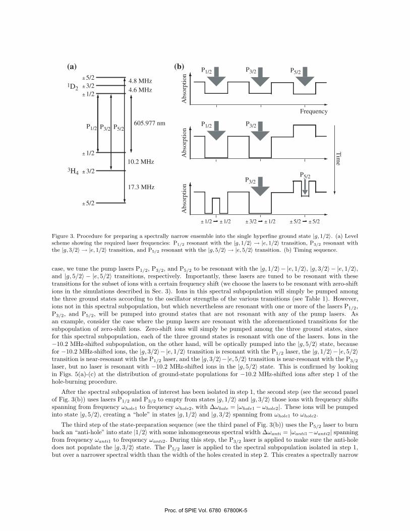
Figure 3. Procedure for preparing a spectrally narrow ensemble into the single hyperfine ground state |g, 1/2〉. (a) Levelscheme showing the required laser frequencies: P1/2 resonant with the |g, 1/2〉 → |e, 1/2〉 transition, P3/2 resonant withthe |g, 3/2〉 → |e, 1/2〉 transition, and P5/2 resonant with the |g, 5/2〉 → |e, 5/2〉 transition. (b) Timing sequence.
case, we tune the pump lasers P1/2, P3/2, and P5/2 to be resonant with the |g, 1/2〉− |e, 1/2〉, |g, 3/2〉 − |e, 1/2〉,and |g, 5/2〉 − |e, 5/2〉 transitions, respectively. Importantly, these lasers are tuned to be resonant with thesetransitions for the subset of ions with a certain frequency shift (we choose the lasers to be resonant with zero-shiftions in the simulations described in Sec. 3). Ions in this spectral subpopulation will simply be pumped amongthe three ground states according to the oscillator strengths of the various transitions (see Table 1). However,ions not in this spectral subpopulation, but which nevertheless are resonant with one or more of the lasers P1/2,P3/2, and P5/2, will be pumped into ground states that are not resonant with any of the pump lasers. Asan example, consider the case where the pump lasers are resonant with the aforementioned transitions for thesubpopulation of zero-shift ions. Zero-shift ions will simply be pumped among the three ground states, sincefor this spectral subpopulation, each of the three ground states is resonant with one of the lasers. Ions in the−10.2 MHz-shifted subpopulation, on the other hand, will be optically pumped into the |g, 5/2〉 state, becausefor −10.2 MHz-shifted ions, the |g, 3/2〉− |e, 1/2〉 transition is resonant with the P1/2 laser, the |g, 1/2〉− |e, 5/2〉transition is near-resonant with the P1/2 laser, and the |g, 3/2〉−|e, 5/2〉 transition is near-resonant with the P3/2
laser, but no laser is resonant with −10.2 MHz-shifted ions in the |g, 5/2〉 state. This is confirmed by lookingin Figs. 5(a)-(c) at the distribution of ground-state populations for −10.2 MHz-shifted ions after step 1 of thehole-burning procedure.
After the spectral subpopulation of interest has been isolated in step 1, the second step (see the second panelof Fig. 3(b)) uses lasers P1/2 and P3/2 to empty from states |g, 1/2〉 and |g, 3/2〉 those ions with frequency shiftsspanning from frequency ωhole1 to frequency ωhole2, with ∆ωhole = |ωhole1 − ωhole2|. These ions will be pumpedinto state |g, 5/2〉, creating a “hole” in states |g, 1/2〉 and |g, 3/2〉 spanning from ωhole1 to ωhole2.
The third step of the state-preparation sequence (see the third panel of Fig. 3(b)) uses the P5/2 laser to burnback an “anti-hole” into state |1/2〉 with some inhomogeneous spectral width ∆ωanti = |ωanti1−ωanti2| spanningfrom frequency ωanti1 to frequency ωanti2. During this step, the P3/2 laser is applied to make sure the anti-holedoes not populate the |g, 3/2〉 state. The P5/2 laser is applied to the spectral subpopulation isolated in step 1,but over a narrower spectral width than the width of the holes created in step 2. This creates a spectrally narrow
Proc. of SPIE Vol. 6780 67800K-5

anti-hole sitting inside a spectrally wider hole in the |g, 1/2〉 state, ensuring an isolated population of ions, withno scattering from ions with similar frequency shifts.
Table 1. Relative oscillator strength for transitions between 3H4 and 1D2 hyperfine manifolds in Pr3+:Y2SiO5. Takenfrom Refs. 10 and 11. Rows (columns) correspond to transitions from different ground (excited) state hyperfine levels.
g/e ±1/2 ±3/2 ±5/2±1/2 0.55 0.38 0.07±3/2 0.40 0.60 0.01±5/2 0.05 0.02 0.93
2. COMPUTATIONAL MODEL
2.1 Program Description
In order to optimize the hole-burning sequence to create a spectral distribution with the desired properties inthe proper hyperfine ground state, we created a computational model of the hole-burning process. The modeluses a truncated Floquet expansion of the semiclassical density matrix equations of motion for a single ion. Forsimple field configurations, the steady-state solution for the ionic density matrix can be obtained by transforminginto a rotating frame in which the equations of motion are time-independent, setting all time-derivatives to zero,and solving the resultant matrix equation. More complicated field configurations, in particular systems in whichmultiple fields couple the same optical transition, generate equations which do not have a time-independentrotating frame. To address such cases, our analysis is carried out in the Fourier domain. When a rotating frameexists, the solution for the transformed variable ω = 0 is identical to the steady-state solution mentioned above.When there is no rotating frame, the set of Fourier-transformed equations is infinite. Higher-order multi-photonprocesses generate terms that oscillate at all harmonics of the beat frequencies between pairs and sets of fields,and contribute additional broadening and light shifts to the optical coherences coupled to the applied fields. Inthe limit that some of these fields are weak compared to DC interactions, the solution of a finite set A of thisinfinite series of equations can be approximated by the solution of set A coupled to a larger but also finite set Bof higher-order terms, and which approximates further higher-order terms as zero.
To form this approximation, we have written a software package using MATLAB † that generates and solvesthe Fourier domain equations of motion that couple to the zero-frequency components of the diagonal of the ionicdensity matrix up to arbitrary order in ion-field interactions. The automatic process by which the equationsare generated makes it possible to consider systems with large numbers of states as easily as simpler two orthree-level systems, limited by the available computational power.
2.2 Physical Parameters
The natural excited state linewidth is taken to be 1/164 µs = 6.10 kHz, with an additional coherence dephasingrate of 1/152 µs−1/164 µs = 481 Hz, using parameters listed in Ref. 10, originally from Equall et al.15 Theground-state relaxation rate is also taken from Ref. 10 to be 1/100 s = 10 mHz, as is the 10 GHz width ofthe inhomogeneous distribution of the optical transition frequency. The ground state coherence dephasing rateis taken to be approximately 1/500 µs = 2 kHz. The coupling coefficients for optical transitions between thedifferent hyperfine states are taken from Ref. 10, and are listed in Table 1.
3. OPTIMIZATION PROCEDURE
Following the three-step hole-burning procedure outlined by Nilsson et al.10, 11 and described in Sec. 1.2, weoptimize each of the three steps over a chosen set of pulse-sequence parameters. The optimization of each of the
†Certain trade names and company products are mentioned in the text or identified in an illustration in order to specifyadequately the experimental procedure and equipment used. In no case does such identification imply recommendation orendorsement by the National Institute of Standards and Technology, nor does it imply that the products are necessarilythe best available for the purpose.
Proc. of SPIE Vol. 6780 67800K-6
three steps is done sequentially, with step 1 first optimized over the chosen parameter space. The state resultingfrom the optimization of the first step is used as input for the optimization of the second step, and so on forthe third step. In the following section, we present the optimization results for step 1 over two parameters. Theoptimization of steps 2 and 3 will be described in a future work.
To gain a physical understanding of the system, we perform a line minimization,16 in which we vary oneparameter at a time, and then iterate until converging on a minimum. That is, we choose a starting set ofparameters, and calculate the first step of the hole-burning sequence while varying one of the parameters, sayparameter 1. We then set parameter 1 to the value found to minimize the figure of merit for step 1, and calculatestep 1 while varying parameter 2. We set parameter 2 to its optimum value and then optimize parameter 3, untilwe have optimized the entire parameter space. This procedure is iterated until the difference between successiveoptima of a given parameter are less than some threshold value. It should be noted that the line minimizationtechnique is not the fastest technique or the most likely to find a true global minimum, but we use it to gaina physical understanding of the system. We intend to confirm the line minimization results in future work byusing a more robust technique such as the simplex method16, 17 or simulated annealing.16
3.1 State Preparation, Step I: Isolating a Spectral Subpopulation
In order to find the optimum set of parameters, it is important to choose appropriate figures of merit for eachstep of the optimization. As discussed in Sec. 1.2, the first step involves the simultaneous application of threelaser fields: one resonant with the |g, 1/2〉 − |e, 1/2〉 transition (P1/2), one resonant with the |g, 3/2〉 − |e, 1/2〉transition (P3/2), and one resonant with the |g, 5/2〉 − |e, 5/2〉 transition (P5/2). It is important to note that“resonant” here means resonant for that spectral subpopulation of ions with zero frequency shift. The importantpoint is that there is one laser resonant with each of the ground states; the specific excited states are chosenfor their oscillator strengths to the various excited states (see Table 1). As mentioned earlier, the goal of thisfirst step is to optically pump all ions with nonzero frequency shift to ground states that are not coupled to anyexcited state by the three laser fields resonant with the zero-shift atoms. This ensures that in the remaining statepreparation, these laser frequencies will only interact with a spectral subpopulation of ions with zero frequencyshift.
The details of the pulse sequence we use for step 1 follow the appendix of Ref. 10. We want to define a spectralsubpopulation of some spectral width ∆ωpop = |ωpop1 − ωpop2| spanning from a start frequency shift ωpop1 to astop frequency shift ωpop2 by sweeping the frequency of the pump lasers P1/2, P3/2, P5/2. The Rabi frequenciesof these lasers are defined as Ω1/2, Ω3/2, and Ω5/2, respectively. We simultaneously sweep the frequencies ofall three pump lasers in a time tsweep, so that each laser is resonant with ωpop1-shifted ions at the start of thesweep, and ωpop2-shifted ions at the end of the sweep. The lasers are not on continuously, but rather pulsed onand off. The total sweep time tsweep is subdivided into periods of duration trep = 1/νrep, where νrep is the pulserepetition rate. Within a single trep, the lasers are all three on for a duration ton at the beginning of trep; forthe remainder of trep, the lasers are off for duration toff = trep − ton. The duty cycle is the percentage of timethe lasers are on, and is defined as ton/trep. The frequencies of all three lasers are swept simultaneously fromωpop1 to ωpop2, with successive pulses being shifted by an amount ωstep = ∆ωpop/(tsweep/trep). This sweep fromωpop1 to ωpop2 it repeated nsweep times.
The figure of merit for the optimization of the first step should quantify the goal of isolating a subpopulationof zero-shift ions. Based on the energy-level structure for a Pr3+ ion with zero frequency shift shown in Fig. 2(a),for each of the three laser fields we can identify the frequency shift that would couple the field to a state otherthan the intended one. The figure of merit should quantify how much population is present in these undesiredstates at frequency shifts that will allow unwanted coupling. For the P1/2 field, a shift of −10.2 MHz for anion in the |g, 3/2〉 state allows resonant coupling of the |g, 3/2〉 − |e, 1/2〉 transition, a shift of −14.8 MHz =(−10.2 MHz−4.6 MHz) allows resonant coupling of the |g, 3/2〉− |e, 3/2〉 transition, and a shift of −19.6 MHz =(−10.2 MHz− 4.6 MHz− 4.8 MHz) allows resonant coupling of the |g, 3/2〉− |e, 5/2〉 transition. Similarly, shiftsof −27.5 MHz , −32.1 MHz = (−27.5 MHz− 4.6 MHz), and −36.9 MHz = (−27.5 MHz− 4.6 MHz− 4.8 MHz)allow couplings of the |g, 5/2〉 − |e, 1/2〉, |g, 5/2〉 − |e, 3/2〉, and |g, 5/2〉 − |e, 5/2〉 transitions, respectively, forions in the |g, 5/2〉 state. Since it is really coupling of these ions to the laser that we are trying to avoid, thepopulations should be weighted by the relevant oscillator strengths (see Table 1). A figure of merit for step 1 of
Proc. of SPIE Vol. 6780 67800K-7

the hole-burning procedure for the field P1/2, which we will denote as FOM1(P1/2), is then the weighted sum ofthe ground-state populations at the frequency shifts that allow various undesired couplings, where the weightingis the oscillator strength for the transition of interest. Specifically, FOM1(P1/2) can be written as:
FOM1(P1/2) =1
2[O(3/2, 1/2)P(3/2,−10.2) + O(3/2, 3/2)P(3/2,−14.8) + O(3/2, 5/2)P(3/2,−19.6) (2)
+ O(5/2, 1/2)P(5/2,−27.5) + O(5/2, 3/2)P(5/2,−32.1) + O(5/2, 5/2)P(5/2,−36.9)],
where O(g,e) represents the oscillator strength between the ground state g and excited state e taken from Table1, P(g, ωshift) is the population remaining in ground state g for frequency shift ωshift, and the factor of 1/2multiplying the entire expression normalizes the sum of the six O(g,e) coefficients to 1 (for the O(g,e) coefficientslisted in Table 1, the sum of each three coefficients for a given ground state are normalized to one). Ideallythis sum should be zero, indicating that there is no population with frequency shifts and in states that allowunwanted scattering. Similar figures of merit, FOM1(P3/2) and FOM1(P5/2), can be calculated for the other twolaser fields, P3/2 and P5/2 respectively
FOM1(P3/2) =1
2[O(1/2, 1/2)P(1/2, 10.2) + O(1/2, 3/2)P(1/2, 5.6) + O(1/2, 5/2)P(1/2, 0.8) (3)
+ O(5/2, 1/2)P(5/2,−17.3) + O(5/2, 3/2)P(5/2,−21.9) + O(5/2, 5/2)P(5/2,−26.7)],
FOM1(P5/2) =1
2[O(1/2, 1/2)P(1/2, 36.9) + O(1/2, 3/2)P(1/2, 32.3) + O(1/2, 5/2)P(1/2, 27.5) (4)
+ O(3/2, 1/2)P(3/2, 26.7) + O(3/2, 3/2)P(3/2, 22.1) + O(3/2, 5/2)P(3/2, 17.3)].
Since the goal of step 1 is to prevent scattering of all three of the pump lasers from ions in frequency classesother than the one of interest, the figure of merit for step 1 of the hole-burning procedure is simply the averageof the figures of merit for each laser individually:
FOM(step1) =1
3
[FOM1(P1/2) + FOM1(P3/2) + FOM1(P5/2)
]. (5)
3.1.1 Results
For starting values of the pulse-sequence parameters of step 1, we use the same parameters as in the appendixof Ref. 10: Ω1/2 = Ω3/2 = Ω5/2 = 1 MHz, ωpop1 = −3 MHz (0 MHz is defined as a zero frequency shift),ωpop2 = +3 MHz, trep = 250 µs, ton = 50 µs, ωstep = 0.6 MHz, and nsweep = 30, resulting in a total numberof 300 excitation pulses for step 1. We assume an initial spectral distribution that is equally distributed from−100 MHz to +100 MHz, with this 200 MHz-wide frequency interval discretized into 1000 frequency classes.
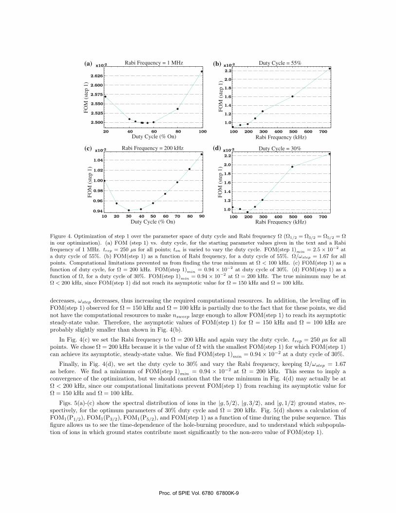
We perform a line optimization16 in the two-parameter space of duty cycle (ton/trep) and Rabi frequency.Fig. 4(a) shows FOM(step 1) calculated for the starting parameters described in the previous paragraph as theduty cycle is varied. ton is changed to vary the duty cycle (ton/trep). trep = 250 µs for all points. A minimumof FOM(step 1)min = 2.5 × 10⁻² at duty cycle of 55% is obtained. Note that for the starting state prior toapplication of the pulse sequence, FOM(step 1) = 1/6 ≈ 0.1667, because the population is normalized to 1 andis equally distributed over 6 ground states: ±5/2, ±3/2, and ±1/2. Ideally, after the pulse sequence we wantFOM(step 1) = 0. Therefore, a value of FOM(step 1)min = 2.5×10⁻² means that 15% of the population remainsin states and frequency classes that allow unwanted couplings to the pump lasers. For all calculations shownin Fig. 4, we make sure that nsweep is large enough to allow FOM(step 1) to reach its asymptotic steady-statevalue. In addition, to calculate FOM(step 1), we first run the pulse sequence, and then wait for 100 ms to allowthe relaxation of the excited-state population. FOM(step 1) is calculated from the ground-state populationsafter the excited state populations have relaxed back to the ground states. Typical populations remaining in theexcited states after waiting 100 ms at the end of the pulse sequence are on the order of a few parts times 10−4.
Sitting at the optimum value of 55% duty cycle, we vary the Rabi frequency of the pump lasers (for allcalculations Ω1/2 = Ω3/2 = Ω5/2), with the result shown in Fig. 4(b). For this optimization, the ratio of the Rabifrequency Ω to the frequency step between successive pulses is kept constant at Ω/ωstep = 1.67. Computationallimitations prevented us from finding the true minimum at Ω < 100 kHz. Since Ω/ωstep is kept constant, as Ω
Proc. of SPIE Vol. 6780 67800K-8
20 40 60 80 100
2.500
2.525
2.550
2.575
2.600
2.626
Duty Cycle (% On)
FO
M (
step
1)
(a) Rabi Frequency = 1 MHz
100 200 300 400 500 600 700
1.0
1.2
1.4
1.6
1.8
2.0
2.2
x10-2 Duty Cycle = 55%
Rabi Frequency (kHz)
FO
M (
step
1)
x10-2(b)
20 40 60 80
0.94
0.96
0.98
1.00
1.02
1.04
x10-2
FO
M (
step
1)
Duty Cycle (% On)10 90705030
(c) Rabi Frequency = 200 kHz (d)
100 200 300 400 500 600 700
1.0
1.2
1.4
1.6
1.8
2.0
2.2
x10-2
Rabi Frequency (kHz)F
OM
(st
ep
1)
Duty Cycle = 30%
Figure 4. Optimization of step 1 over the parameter space of duty cycle and Rabi frequency Ω (Ω1/2 = Ω3/2 = Ω5/2 = Ωin our optimization). (a) FOM (step 1) vs. duty cycle, for the starting parameter values given in the text and a Rabifrequency of 1 MHz. trep = 250 µs for all points; ton is varied to vary the duty cycle. FOM(step 1)min = 2.5 × 10⁻² ata duty cycle of 55%. (b) FOM(step 1) as a function of Rabi frequency, for a duty cycle of 55%. Ω/ωstep = 1.67 for allpoints. Computational limitations prevented us from finding the true minimum at Ω < 100 kHz. (c) FOM(step 1) as afunction of duty cycle, for Ω = 200 kHz. FOM(step 1)min = 0.94 × 10⁻² at duty cycle of 30%. (d) FOM(step 1) as afunction of Ω, for a duty cycle of 30%. FOM(step 1)min = 0.94 × 10⁻² at Ω = 200 kHz. The true minimum may be atΩ < 200 kHz, since FOM(step 1) did not reach its asymptotic value for Ω = 150 kHz and Ω = 100 kHz.
decreases, ωstep decreases, thus increasing the required computational resources. In addition, the leveling off inFOM(step 1) observed for Ω = 150 kHz and Ω = 100 kHz is partially due to the fact that for these points, we didnot have the computational resources to make nsweep large enough to allow FOM(step 1) to reach its asymptoticsteady-state value. Therefore, the asymptotic values of FOM(step 1) for Ω = 150 kHz and Ω = 100 kHz areprobably slightly smaller than shown in Fig. 4(b).
In Fig. 4(c) we set the Rabi frequency to Ω = 200 kHz and again vary the duty cycle. trep = 250 µs for allpoints. We chose Ω = 200 kHz because it is the value of Ω with the smallest FOM(step 1) for which FOM(step 1)can achieve its asymptotic, steady-state value. We find FOM(step 1)min = 0.94× 10⁻² at a duty cycle of 30%.
Finally, in Fig. 4(d), we set the duty cycle to 30% and vary the Rabi frequency, keeping Ω/ωstep = 1.67as before. We find a minimum of FOM(step 1)min = 0.94 × 10⁻² at Ω = 200 kHz. This seems to imply aconvergence of the optimization, but we should caution that the true minimum in Fig. 4(d) may actually be atΩ < 200 kHz, since our computational limitations prevent FOM(step 1) from reaching its asymptotic value forΩ = 150 kHz and Ω = 100 kHz.
Figs. 5(a)-(c) show the spectral distribution of ions in the |g, 5/2〉, |g, 3/2〉, and |g, 1/2〉 ground states, re-spectively, for the optimum parameters of 30% duty cycle and Ω = 200 kHz. Fig. 5(d) shows a calculation ofFOM1(P1/2), FOM1(P3/2), FOM1(P5/2), and FOM(step 1) as a function of time during the pulse sequence. Thisfigure allows us to see the time-dependence of the hole-burning procedure, and to understand which subpopula-tion of ions in which ground states contribute most significantly to the non-zero value of FOM(step 1).
Proc. of SPIE Vol. 6780 67800K-9

Frequency (MHz)
Po
pu
lati
on
(a) -5/2 Ground State (b)
(c)
-100 -50 0 50 100
0.1
0.2
0.3
0.4
0.5
-100 -50 0 50 100
0.1
0.2
0.3
0.4
0.5-3/2 Ground State
Po
pu
lati
on
Frequency (MHz)
-100 -50 0 50 100
0.1
0.2
0.3
0.4
0.5-1/2 Ground State
Frequency (MHz)
Po
pu
lati
on
(d)
Fig
ure
of
Meri
t
Time (ms)
t=0 ms
t=12.25 ms
t=198 ms
P1/2
P3/2P5/2
Step 1
50 100 150 200
0.025
0.05
0.075
0.1
0.125
0.15
0.175
0
0
Figure 5. Spectral distribution of ions at various times during the optimum pulse sequence. For all panels, the duty cycle30% and Ω = 200 kHz. (a-c) Population of ions in the |g,−5/2〉, |g,−3/2〉, and |g,−1/2〉 states, respectively, as a functionof frequency shift. (Traces for the degenerate |g, +5/2〉, |g,+3/2〉, and |g,+1/2〉 states are identical.) Nine traces areshown, for times t = 0, t = 12.25 ms, and every 12.25 ms until 85.75 ms. The last trace is at t = 198 ms due to the 100 mswait after the pulse sequence to allow the excited-state population to relax. Each trace corresponds to one of the pointsin panel (d). (d) FOM1(P1/2), FOM1(P3/2), FOM1(P5/2), and FOM(step 1) versus time for the pulse sequence depictedin panels (a)-(c).
In future work, we would like to extend our computational capabilities to allow us to find a true minimum ofRabi frequency, and also to confirm these results with a more robust optimization method, such as the simplexmethod16, 17 or simulated annealing.16 We would also like to optimize over a larger parameter space. At thetime of this writing, we have not had time to perform the optimization for steps 2 and 3 of the hole-burningsequence. However, in the next two sections, we describe these steps, as well as the figures of merit that will beused in their optimization.
3.2 State Preparation, Step II: Hole Burning
In the second step of the hole-burning procedure, two laser fields are simultaneously applied: one resonant withthe |g, 1/2〉 − |e, 1/2〉 transition (P1/2 in Fig. 3), and one resonant with the |g, 3/2〉 − |e, 1/2〉 transition (P3/2
in Fig. 3). The goal of this step is to empty all population of near-zero-shift ions (ions having a frequency shiftin some range from ωhole1 to ωhole2, with ωhole1 < 0 < ωhole2) from the |g, 1/2〉 and |g, 3/2〉 states by pumpingthese ions to the |g, 5/2〉 state. This creates “holes” in the |g, 1/2〉 and |g, 3/2〉 state populations for ions inthe frequency shift range ωhole1 to ωhole2. The value of ∆ωhole = |ωhole1 − ωhole2| should be large enough toprovide a zero-population background around the anti-hole we pump back into state |g, 1/2〉 in step 3. The holein the |g, 3/2〉 state is required to allow a zero background for the small population that is written to the |g, 3/2〉state in the write process, and also to have zero background from which to retrieve this created coherence in theretrieve process (see Sec. 1.1).
The figure of merit for the optimization of the second step should quantify the goal of creating zero populationholes in the |g, 1/2〉 and |g, 3/2〉 states over the frequency interval from ωhole1 to ωhole2. Therefore the figure of
Proc. of SPIE Vol. 6780 67800K-10

merit should simply be the integrated population of the |g, 1/2〉 state over the frequency range ωhole1 to ωhole2
plus the integrated population of the |g, 3/2〉 state over the frequency range ωhole1 to ωhole2.
3.3 State Preparation, Step III: Burning Back an Anti-Hole
As shown in the third panel of Fig. 3(b), the third step involves burning back an “anti-hole” into the state|g, 1/2〉. This is accomplished by applying the P3/2 laser to preserve the hole in the |g, 3/2〉 state created in step2, while simultaneously applying the P5/2 laser to pump population (referred to as an “anti-hole”) into the P1/2
state. The P5/2 laser is applied to the zero-frequency-shift spectral subpopulation, but over a narrower spectralwidth than the width of the holes created in step 2. This creates a spectrally narrow anti-hole sitting inside aspectrally wider hole in the |g, 1/2〉 state, ensuring an isolated population of ions, with no scattering from ionswith nearby frequency shifts.
The figure of merit we propose for step 3 is based on recent theoretical understanding of the importance of theinhomogeneously broadened spectral lineshape of an ensemble to the EIT-based storage and retrieval efficiency.13
In the DLCZ protocol shown in Fig. 1 and described in Sec. 1.1, the write step used to generate entanglementcreates an atomic coherence between hyperfine ground states that is stored in the ensemble until the retrievalstep used for entanglement swapping. This retrieval step is based on EIT,5–8 and therefore the fidelity of thequantum-memory node depends on the EIT-based retrieval efficiency. Recent work by Gorshkov et al.13 suggeststhat for an inhomogeneously broadened ensemble such as the anti-hole created in step 3, the retrieval efficiencyis maximized for distributions with tails that fall off faster than those of a Lorenztian distribution. We thereforepropose the sharpness of the fall-off of the tails of the anti-hole spectral distribution as the figure of merit forthe optimization of step 3.
4. CONCLUSIONS AND FUTURE WORK
We have described a scheme for using Pr3+:Y2SiO5 as a quantum-memory node in a DLCZ-type12 quantumrepeater scheme, including a detailed description of the necessary state preparation. We have constructed acomputational model of the hole-burning process used to prepare the initial spectral distribution in order tooptimize the state-preparation procedure. We have introduced figures of merit for the optimization of each ofthe three steps of the hole-burning procedure, and found the optimum parameters for the first of these three steps.In future work, we will complete the optimization of steps 2 and 3, in addition to confirming the optimizationresults with a more robust optimization method such as simplex16, 17 or simulated annealing.16 In addition, weare constructing an experimental setup to test the optimization results, and to implement the DLCZ quantum-repeater scheme using Pr3+:Y2SiO5 .
ACKNOWLEDGMENTS
We acknowledge helpful discussions with A. V. Gorshkov and H. J. Lynch. M.D.E. acknowledges support fromthe NRC/NIST Postdoctoral Fellowship.
REFERENCES
1. H.-J. Briegel, W. Dur, J. I. Cirac, and P. Zoller, “Quantum Repeaters: The Role of Imperfect LocalOperations in Quantum Communication,” Physical Review Letters 81, p. 5932, 1998.
2. E. Fraval, M. J. Sellars, and J. J. Longdell, “Method of Extending Hyperfine Coherence Times inPr3+:Y2SiO5,” Physical Review Letters 92(7), p. 077601, 2004.
3. E. Fraval, M. J. Sellars, and J. J. Longdell, “Dynamic Decoherence Control of a Solid-State Nuclear-Quadrupole Qubit,” Physical Review Letters 95(3), p. 030506, 2005.
4. J. J. Longdell, E. Fraval, M. J. Sellars, and N. B. Manson, “Stopped Light with Storage Times Greater thanOne Second Using Electromagnetically Induced Transparency in a solid,” Physical Review Letters 95(6),p. 063601, 2005.
5. D. F. Phillips, A. Fleischhauer, A. Mair, and R. L. Walsworth, “Storage of Light in Atomic Vapor,” Phys.Rev. Lett. 86, pp. 783–786, 2001.
Proc. of SPIE Vol. 6780 67800K-11

6. C. Liu, Z. Dutton, C. H. Behroozi, and L. V. Hau, “Observation of coherent optical information storage inan atomic medium using halted light pulses,” Nature 409, pp. 490–493, 2001.
7. T. Chaneliere, D. N. Matsukevich, S. D. Jenkins, S.-Y. Lan, T. A. B. Kennedy, and A. Kuzmich, “Storageand retrieval of single photons transmitted between remote quantum memories,” Nature 438, pp. 833–836,2005.
8. M. D. Eisaman, A. Andre, F. Massou, M. Fleischhauer, A. Zibrov, and M. D. Lukin, “Electromagneticallyinduced transparency with tunable single-photon pulses,” Nature 438, pp. 837–841, 2005.
9. H. de Riedmatten, J. Laurat, C. W. Chou, E. Schomburg, D. Felinto, and H. J. Kimble, “Direct Measurementof Decoherence for Entanglement between a Photon and a Stored Atomic Excitation,” Physical ReviewLetters 97, p. 113603, 2006.
10. M. Nilsson, L. Rippe, S. Kroll, R. Klieber, and D. Suter, “Hole-burning techniques for isolation and studyof individual hyperfine transitions in inhomogeneously broadened solids demonstrated in Pr3+:Y2SiO5,”Physical Review B (Condensed Matter and Materials Physics) 70(21), p. 214116, 2004.
11. M. Nilsson, L. Rippe, S. Kroll, R. Klieber, and D. Suter, “Erratum: Hole-burning techniques for isolation andstudy of individual hyperfine transitions in inhomogeneously broadened solids demonstrated in Pr3+:Y2SiO5
[Phys. Rev B 70, 214116 (2004)],” Physical Review B (Condensed Matter and Materials Physics) 71(14),p. 149902, 2005.
12. L. M. Duan, M. D. Lukin, J. I. Cirac, and P. Zoller, “Long-distance quantum communication with atomicensembles and linear optics,” Nature 413, pp. 414–418, 2001.
13. A. V. Gorshkov, A. Andre, M. D. Lukin, and A. S. Sorensen, “Photon storage in lambda-type opticallydense atomic media. III. Effects of inhomogeneous broadening,” http://arxiv.org/quant-ph/0612084 .
14. C. W. Chou, H. de Riedmatten, D. Felinto, S. V. Polyakov, S. J. van Enk, and H. J. Kimble, “Measurement-induced entanglement for excitation stored in remote atomic ensembles,” Nature 438, pp. 828–832, 2005.
15. R. W. Equall, R. L. Cone, and R. M. Macfarlane, “Homogeneous broadening and hyperfine structure ofoptical transitions in Pr3+:Y2SiO5,” Phys. Rev. B 52(6), pp. 3963–3969, 1995.
16. W. H. Press, B. P. Flannery, S. A. Teukolsky, and W. T. Vetterling, Numerical Recipes in C: The Art ofScientific Computing, Cambridge University Press, New York, 1988.
17. J. A. Nelder and R. Mead, “A simplex method for function minimization,” Computer Journal 7, pp. 308–313,1965.
Proc. of SPIE Vol. 6780 67800K-12