optimized motion series - ifpusa.com oms.pdf · sizing and selection is also a snap using the...
TRANSCRIPT

www.festo.com
Optimized Motion Series
Easy for you!
Complete solutionEasily size the OMS axis for your application using the catalog data. Or use PositioningDrives, the Festo sizing software.
Specify and order the entire axis including actuator, motor, cables, and drive using a single order code.
The entire axis is delivered together with the motor already mounted to the actuator.
Easily configure the solution using a web browser.
Best performanceSelect from:• Electric cylinder EPCO for
flexible positioning and clamping
• Toothed belt actuator ELGR for automating simple movements
• Rotary actuators ERMO for rotary and swivel motions
• Closed-loop drive CMMO-ST for easy configuration and operation. Supports digital I/O, Modbus TCP and IO-Link control interfaces.
Optimized Motion Series (OMS) offers electrical axes with optimized performance at significantly lower cost than conventional electrical solutions. Each OMS axis consists of an electromechanical actuator with permanently mounted motor, a set of cables and a drive. Easy sizing and selection, ordering and commissioning makes the OMS products a breeze to work with.
Easy• Select the axis to best meet
your application needs• Order using a single type
code• All axis components
delivered together fast
Save time• Configure positions and
motion profiles quickly via a web browser
Flexible• Support your applications
with a wide range of linear and rotary actuators
• Specify the position, force and speed setpoints for your application
• Define your desired motion profiles
Highlights
Simplicity

2 Optimised Motion Series – Errors and omissions excepted – 2015/10
A complete system
It doesn't get more convenient: simply enter the order code and you quickly receive the complete system. As a result the workload in your purchasing department is reduced, warehousing and logistics are simplified and you save time because the individual components no longer have to be assembled.
Sizing and selection is also a snap using the characteristic curves in the catalog or the Festo engineering software PositioningDrives.
Simpler and easier than ever before: Quickly and easily monitor and configure the axis via a web browser on your computer, tablet or smartphone.
Use the web browser to:• Remotely monitor the drive
status, including actuator position, drive enabled, output stage temperature and more
• Detect and clear faults• Specify or teach the position
setpoints and motion profiles when commissioning the axis
Do you require more sophisticated control from OMS?
Configure the CMMO-ST drive using the Festo Configuration Tool (FCT) instead of your web browser. FCT offers advanced functionality when configuring the CMMO-ST drive, including:• Force and speed setpoint
control
• Configuration of up to 64 setpoints and motion profiles
• Sophisticated sequencing between movements
• Position, force, speed and time comparators to monitor and react to the state of axis
• Extensive diagnostic functions FCT is free to download and use from the Festo website.
Data from the Festo parameter cloud:Download the latest predefined parameter sets for your axis from the Festo parameter cloud. These parameter sets have been tested and optimized to guarantee the best performance.
Optimized logistics: the complete positioning system in a single box (1 system = 1 order code)
Here's how it works:1. Connect the closed-loop drive
CMMO-ST to your computer2. Enter the IP address of the
drive in your web browser3. Specify your axis configuration
and download the parameter file from the Festo parameter cloud
4. Download the parameter file from your computer to the CMMO-ST
5. Enable and home the axis 6. Enter the position setpoints
and motion profiles7. Download and save them
directly in the CMMO-ST8. You are ready to go!
Optimized Motion Series – Errors and omissions excepted – 02/2016

2015/10 – Errors and omissions excepted – Optimised Motion Series 3
Selection made easy!
The Festo engineering software PositioningDrives makes it easy to size and select a Festo axis to meet your application needs. Simply input your application data into PositioningDrives.
PositionDrives will calculate the best solutions for your application.
PositioningDrives prevents incorrect designs and energy waste by helping you select solutions that are properly sized for your application
Ideal for controlling small systems:The controller CECC is a modern, compact, and versatile PLC. Well-suited for control of small machines, machine subprocesses, and OMS axes.Control OMS axes via Modbus TCP, IO-Link, Ethernet TCP/IP, or digital I/O.
CECC integrated functionality includes:• CANopen Master• IO-Link• Modbus TCP• Digital I/O• Serial protocolsControl Festo electric drives via Modbus TCP, CANopen, IO-Link or digital I/O.
Control Festo valve manifolds via CANopen or Festo I-port
The CECC communicates seamlessly via Ethernet TCP/IP with other Festo devices, including:• Controllers• HMI operator units CDPX• Camera SBOx-Q for image
evaluation
The CECC is configured and programmed using CODESYS V3. Integrated functional libraries ensure quick and easy programming. CODESYS V3 is free to download and use from the Festo website.
Power supply unit CACN24 V DC power supply for logic and load
Optimized logistics: the complete positioning system in a single box (1 system = 1 order code)
Optimized Motion Series – Errors and omissions excepted – 02/2016 02/2016 – Errors and omissions excepted – Optimized Motion Series

4 Optimised Motion Series – Errors and omissions excepted – 2015/10
Electric cylinder EPCO
Guide unit (optional)• Recirculating ball bearing guide
with high load bearing capacity• Absorption of lateral forces and
torques to protect the piston rod• Integrated mounting interfaces
for other actuators. For example:
− Toothed belt axis ELGR − Rotary actuator ERMO − Electric slide EGSL − Pneumatic slide DGSL
• Technical data (size 16/25/40) − Max. lateral forces Fy/z
355/415/510 N − Max. torque Mx 13/19/27 Nm − Max. torque My 9/12/20 Nm
Piston rod• Male thread standard
Optional:• Piston rod with female thread• Piston rod extension
Diverse piston rod accessories, e.g.• Rod eye• Rod clevis• Coupling
End-position cushioning• Absorbs impact energy
in both end-positions• Reduced load and noise
Diverse cylinder mounting options, e.g.• Foot mounting• Flange mounting• Swivel mounting• Adapter kit
Ball screw actuator• 2 pitches per size• Non-rotating piston rod• Life-time lubrication
Flexible positioning and clamping
The electric cylinder EPCO offers an array of features to support a wide range of applications. Available in 3 sizes, 2 ball screw pitches per size, and stroke lengths up to 400 mm, the EPCO delivers the forces and speeds needed for light duty applications.
The optional guide unit makes the EPCO even more powerful and versatile. And with a running performance of 10,000 km, the EPCO is built to last.
Optimized Motion Series – Errors and omissions excepted – 02/2016

2015/10 – Errors and omissions excepted – Optimised Motion Series 5
CleanLook with smooth surfaces• Less susceptible to
contamination• Easy to clean
Flexible positioning and clamping
Technical data
Size 16 25 40
Design Electric cylinder with recirculating ball screw and motor
Working stroke [mm] 50 ... 200 50 ... 300 50 ... 400
Screw pitch [mm/rev] 3 8 3 10 5 12.7
Max. effective horizontal load [kg] 24 8 60 20 120 40
Max. effective vertical load [kg] 12 4 30 10 60 20
Max. feed force Fx [N] 125 50 350 105 650 250
Max. speed [mm/s] 125 300 150 500 180 460
Max. acceleration [m/s²] 10
Repeatability [mm] ±0.02
Cables for motor and encoder• Pre-assembled, up to 10 m
long• Suitable for energy chains• Shielded for noise immunity• Robust connectors ensure no
loss of connection
Motor connection• Freely selectable outlet
direction for the motor cables• Standard direction: top
Motor• Holding brake (optional) • Encoder standard for closed-
loop operation• Without encoder (optional)
Optional position sensing• Specify the “position sensing”
option as "via proximity sensor"
• Select your preferred sensor bracket:
− Sensor rail (aluminum) − Mounting kit in clean design
(polymer)
− Select your preferred sensor/proximity sensor (SMT-8 or SME-8) depending on the application
• Bond the sensor bracket into place, mount the sensor and you're done!
Optimized Motion Series – Errors and omissions excepted – 02/2016 02/2016 – Errors and omissions excepted – Optimized Motion Series

6 Optimised Motion Series – Errors and omissions excepted – 2015/10
Toothed belt axis ELGR
Dynamic and cost-effective motion
End-position sensing via inductive proximity switch SIES-8M (optional)• Switching output PNP or NPN• Switching distance 1.5 mm• Repeatability ±50 μm (radial)• Output status display: 2 yellow
LEDs for improved visibility• Cable lengths up to 7.5 m• Electrical connection:
3-wire cable or 3-pin M8• The sensor bracket, switch lug
and proximity switch SIES-8M can be retrofitted onto the axis at any time.
Guide variants• Recirculating ball bearing
guide − 4 backlash-free preloaded
guides − For medium loads − Very good torque handling
• Plain-bearing guide (on request)
− For small loads − Use in humid environments
or with non-abrasive dusts
Flexible mounting orientation with profile mounts MUE• On the end cap• On the carriage• Either horizontal or vertical
Mounted on the bearing cap Mounted on the slide
The toothed belt axis ELGR is ideal for simple motion applications that require a very cost-effective solution. Available in 3 sizes, in stroke lengths up to 1.5 m, and capable of speeds up to 1.1 m/s, the ELGR can support a broad range of applications. And the use of recirculating ball bearing guides means the ELGR can run for up to 5,000 km of service life.
Optimized Motion Series – Errors and omissions excepted – 02/2016

2015/10 – Errors and omissions excepted – Optimised Motion Series 7
Dynamic and cost-effective motion
Cables for motor and encoder• Pre-assembled, up to 10 m
long• Suitable for energy chains• Shielded for noise immunity• Robust connectors ensure no
loss of connection
Motor positions and orientations• Freely selectable motor
positions at both ends of the actuator
• Freely selectable outlet direction for the motor cables
• Can be changed at any time
Motor• Holding brake (optional)• Encoder standard for closed-
loop operation• Without encoder (optional)
Technical data
Size 35 45 55
Design Electromechanical linear axis with toothed belt
Guide Recirculating ball bearing guide
Standard stroke [mm] 50, 100, 150, ... , 750,800
50, 100, 150, ..., 750,800, 900, 1000
50, 100, 150, ..., 750,800, 900, 1000, ..., 1500
Max. feed force Fx [N] 50 100 350
Max. speed [m/s] 1.1 1.1 0.35
Max. acceleration [m/s²] 15
Repeatability [mm] ±0.1
Permissible forces and torques for a service life of 5000 km
Fy max. Fz max. [N] 28 50 68
Mx max. [Nm] 2.5 5 15
My max. [Nm] 8 16 48
Mz max. [Nm] 8 16 48
Optimized Motion Series – Errors and omissions excepted – 02/2016 02/2016 – Errors and omissions excepted – Optimized Motion Series

8 Optimised Motion Series – Errors and omissions excepted – 2015/10
Rotary actuator ERMO
Infinite turning under high load
Swivel angle limitation (optional)• Use adjustable stop kit
EADP to limit rotary angle within 270º
Mechanical interfaces• Flange and housing are
identical to the Festo pneumatic swivel module DSM
• Consider in place of DSM
Through-feed• Sealed hollow shaft• For energy or sensor cables• For tubing
Robust and precise bearing• Backlash-free ball bearings• Absorption of high lateral
forces
The rotary axis ERMO offers a complete solution for turning and aligning parts and workpieces even when subject to heavy loads. And the rugged design of the ERMO gives it a long service life of more than 5 million cycles.
The ERMO is also suitable for simple rotary indexing table applications such as in assembly applications. The flexibility of the ERMO and its diverse range of possible uses make it ideal for simpler applications requiring a cost-effective solution.
Optimized Motion Series – Errors and omissions excepted – 02/2016

2015/10 – Errors and omissions excepted – Optimised Motion Series 9
Infinite turning under high load
Reference sensor• For homing to sensor• M8 connection
Mounting interfacesFor connecting to other actuators. For example:• Electric cylinder EPCO
with guide unit• Electric slide EGSL
Technical data
Size 12 16 25 32
Flange size [mm] 59x59 70x70 83x83 105x105
Torque [Nm] 0.15 0.8 2.5 5
Max. mass moment of inertia [kg.cm²] 3 13 65 164
Speed [°/s] 600 600 400 300
Repeatability [°] ±0.05 ±0.05 ±0.05 ±0.1
Max. axial force [N] 500 600 700 800
Max. radial force [N] 500 750 1200 2000
Cables for motor and encoder• Pre-assembled, up to 10 m
long• Suitable for energy chains• Shielded for noise immunity• Robust connectors ensure no
loss of connectionMotor orientation• Motor cables can be oriented:
top, left and right• Can be changed at any timeMotor• Holding brake (optional)• Encoder standard for closed-
loop operation• Without encoder (optional)
CleanLook with smooth surfaces• Less susceptible
to contamination
Optimized Motion Series – Errors and omissions excepted – 02/2016 02/2016 – Errors and omissions excepted – Optimized Motion Series

10 Optimised Motion Series – Errors and omissions excepted – 2015/10
Optimized Motion Series gantries
Multi-axis solutions made easy
Quickly and conveniently create multi-axis solutions.
Optimized Motion Series gantries are simple to assemble, commission and operate. Consider these low-cost solutions when you need to pick, place, lift, rotate, assemble and package small components. Control one, two and three directions of motion.
Pick, place and rotate• Electric linear gantry with ELGR and EPCO-KF• Plus rotary actuator ERMO
No mounting plates required• Mounting interfaces built
into the actuators• Save time on assembly• Save money on components
Repeatable assembly• Alignment holes machined
into every actuator• Centering sleeves between
axes provide consistent alignment for precise assembly of gantries
Applications• Lightweight pick and place • Packaging small components• Moving and rotating test tubes• Assembly of electronics• Pressing parts into subassemblies • And many more...
Dynamic solution• ELGR with EPCO-KF makes for a
dynamic two-axis gantry• ELGR toothed-belt actuators can
cover distances over 1m and achieve speeds up to 1.1 m/s
Optimized Motion Series – Errors and omissions excepted – 02/2016

2015/10 – Errors and omissions excepted – Optimised Motion Series 11
Multi-axis solutions made easy
Rotary lift solution• Electric cylinder EPCO-KF• Rotary actuator ERMO
Precise solution• Two electric cylinders
EPCO-KF• EPCO with ball screw
offers very repeatable movements
Narrow profile solution• Two electric cylinders
EPCO-KF• Vertical orientation
ensures a narrow profile
Hybrid solution• Electric cylinder EPCO-KF• Pneumatic slide DGSL
GrippersSelect from a wide range of Festo grippers to complete your handling solution (additional mounting hardware may be required)
Optimized Motion Series – Errors and omissions excepted – 02/2016 02/2016 – Errors and omissions excepted – Optimized Motion Series

12 Optimised Motion Series – Errors and omissions excepted – 2015/10
Optimized Motion Series gantries
How it works
1. Select the desired combinations of axes from the data tables below.2. Use the associated mounting hardware. Mounting hardware consists of standard screws, washers and Festo accessories including
centering sleeves and slot nuts.
ELGR with EPCO-KF
Through holes (x4)
ELGR sze EPCO-KF size Slot nuts* Centering sleeves* Screws Washers
35 16 NST-3-M3 (x4) ZBH-7 (x2) M3x10 (x4) --
45 25 NST-5-M5 (x4) ZBH-7 (x2) M5x50 (x4) DIN125-A5.3 (x4)
55 40 NST-5-M5 (x4) ZBH-7 (x2) M5x65 (x4) DIN125-A5.3 (x4)
EPCO-KF with ERMO
Slot nuts (x4)
EPCO-KF size ERMO size Centering sleeves* Screws
16 12 ZBH-7 (x2) M4x16 (x2)
25 16 ZBH-7 (x2) M5x18 (x2)
40 25 ZBH-7 (x2) M5x20 (x2)
Through holes (x2)Threaded holes (x2)
DGSL size ERMO size Centering sleeves* Screws
12 12 ZBH-7 (x2) M4x18 (x2)
20 25 ZBV-9-7 (x2) M5x22 (x2)
25 25 ZBV-9-7 (x2) M5x22 (x2)
EGSL size ERMO size Centering sleeves* Screws
35 12 ZBH-7 (x2) M4x12 (x2)
45 16 ZBH-7 (x2) M5x12 (x2)
55 25 ZBH-7 (x2) M5x14 (x2)
55 32 ZBH-7 (x2) M5x14 (x2)
Consider additional mounting options with ERMO• DGSL pneumatic slide with ERMO• EGSL electric slide with ERMO
Through holes (x2)Threaded holes (x2) Through holes (x2)Threaded holes (x2)
*Festo accessories
*Festo accessories
*Festo accessories
Optimized Motion Series – Errors and omissions excepted – 02/2016
2015/10 – Errors and omissions excepted – Optimised Motion Series 13
How it works
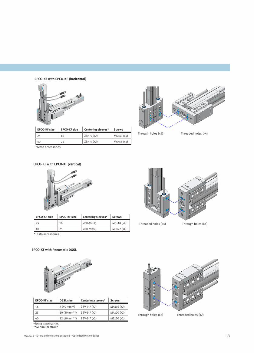
EPCO-KF with EPCO-KF (horizontal)
EPCO-KF size EPCO-KF size Centering sleeves* Screws
25 16 ZBH-9 (x2) M6x40 (x4)
40 25 ZBH-9 (x2) M6x55 (x4)
Threaded holes (x4)Through holes (x4)
EPCO-KF with EPCO-KF (vertical)
EPCO-KF size EPCO-KF size Centering sleeves* Screws
25 16 ZBH-9 (x2) M5x18 (x4)
40 25 ZBH-9 (x2) M5x22 (x4)
Through holes (x4)Threaded holes (x4)
EPCO-KF with Pneumatic DGSL
Threaded holes (x2)Through holes (x2)
EPCO-KF size DGSL size Centering sleeves* Screws
16 8 (40 mm**) ZBV-9-7 (x2) M4x16 (x2)
25 10 (30 mm**) ZBV-9-7 (x2) M4x20 (x2)
40 12 (40 mm**) ZBV-9-7 (x2) M5x20 (x2)
*Festo accessories**Minimum stroke
*Festo accessories
*Festo accessories
Optimized Motion Series – Errors and omissions excepted – 02/2016 02/2016 – Errors and omissions excepted – Optimized Motion Series

14 Optimised Motion Series – Errors and omissions excepted – 2015/10
Accessories and applications
Festo accessories
Description Qty/package Type code Screws
Centering sleeve 10 ZBH-7 186717
Centering sleeve 10 ZBH-9 150927
Centering sleeve 10 ZBV-9-7 548805
Slot nut 1 NST-3-M3 558045
Slot nut 1 NST-5-M5 150914
Versatile range of applications for the electric cylinder EPCO
Lifting/stacking Positioning workpieces Transferring Stopping/separating
Press fitting Setting deflectors Tilting Filling/taking samples
Optimized Motion Series – Errors and omissions excepted – 02/2016

2015/10 – Errors and omissions excepted – Optimised Motion Series 15
Quick and easy configuration - controlled positioning
The closed-loop drive CMMO-ST offers quick and easy monitoring and configuration via a web browser. And with support for IO-Link, Modbus TCP or digital I/O, the CMMO-ST is easily controlled from your PLC.
CMMO-ST is a closed-loop servo controller for stepper motors. It uses a sophisticated control algorithm to create smooth motions and minimize motor noise. Additionally, as a fully fledged closed-loop servo system, the CMMO-ST uses an optimized motor characteristic curve for the highest degree of operational reliability and fast dynamic response.
Sophisticated functions• Acceleration with jerk
limitation• Monitoring of positions and
torque ranges• Comparators for monitoring
process variables including torque, position, speed and time
• Positioning mode with optional torque limiter
• Force mode with optional stroke limit
• Speed mode with stroke and force limiter
Key technical data• Logic voltage: 24 V DC
(isolated from load)• 24 V DC load voltage• Maximum motor current: 5 A• Switching logic: PNP or NPN• Safety: STO/cat. 3, PLd• Protection class: IP40
IO-Link and Modbus TCPThe Festo Handling and Positioning Profile (FHPP) is supported for monitoring and controlling the CMMO-ST from your PLC.
Power supply (separate for logic and load)
I/O interface
IO-Link interface
Display (7-segment display)
Mounting options for closed-loop drive CMMO-ST (IP40 protection)
Flat back mounting Book spine mounting H-rail mounting
Ethernet interface• Modbus TCP/Server• Web server/HTTP• FCT commissioning software
Safety function “Safe Torque Off” (STO)
Reference switch
Overview of interfaces
Closed-loop drive CMMO-ST
Optimized Motion Series – Errors and omissions excepted – 02/2016 02/2016 – Errors and omissions excepted – Optimized Motion Series

Productivity
Maximum productivity is a question of ambitionDo you share this attitude? We will be glad to help you achieve this goal – through our four outstanding qualities: • Security • Efficiency • Simplicity • Competency
We are the engineers of productivity.
Discover new dimensions for your company: www.festo.com/whyfesto
1311
3628
en
0
2.20
16 –
Err
ors
and
omis
sion
s ex
cept
ed