optimized implementation of fft processor for …€¦ · an optimized implementation of the...
TRANSCRIPT

International Journal of Advances in Engineering & Technology, May 2012.
©IJAET ISSN: 2231-1963
429 Vol. 3, Issue 2, pp. 429-441
OPTIMIZED IMPLEMENTATION OF FFT PROCESSOR FOR
OFDM SYSTEMS
1Pradeepa. M,
2Gowtham. P 1PG Scholar,
2Assistant Professor
1,2 SNS College of Technology, Coimbatore-, India
ABSTRACT
Due to the advanced VLSI technology, Fast Fourier Transform (FFT) and Inverse Fast Fourier Transform
(IFFT) has been applied to wide field of digital signal processing (DSP) applications. For modern
communication systems, the FFT/IFFT is very important in the OFDM. Because of FFT/IFFT is the key
computational block to execute the baseband multicarrier demodulation and modulation in the OFDM system.
The Fast Fourier Transform (FFT) and its inverse transform (IFFT) processor are key components in OFDM
systems. An optimized implementation of the 8-point FFT processor with radix-2 algorithm in R2MDC
architecture is the processing element. This butterfly- Processing Element (PE) used in the 8-FFT processor
reduces the multiplicative complexity by using a real constant multiplication in one method and eliminates the
multiplicative complexity by using add and shift operations in this proposed method.
KEYWORDS: Cooley-Tukey, R2MDC, FFT, VHDL, OFDM.
I. INTRODUCTION
In the last few years, wireless communication plays a significant role in people’s life. The
development of wireless communication science and technology was extremely fast due to VLSI
technology. Many complicated design of communication system become feasible. There is a rapidly
growing demand for high speed, efficient and reliable digital communication system with the purpose
of support multimedia transmission such as high-quality voice, video, etc. Orthogonal Frequency
Division Multiplexing (OFDM) technology is an effective modulation scheme to meet the demand.
This is an advanced modulation technique that effectively expands channel utilization and reduces
inter-symbol interference (ISI) and inter-carrier interference (ICI) caused by multi-path effect.
Multiple-input multiple-output (MIMO) signal processing technique has been utilized in combination
with OFDM for next generation wireless communication system to enhance link throughput as well as
the robustness of transmission over frequency selective fading channel. FFT algorithms are based on
the fundamental principle of decomposing the computation of the DFT of a sequence of length N into
successively smaller DFT using the symmetry, periodicity, compressibility and expansibility
properties of WN .The manner in which this principle is implemented leads to a variety of different
algorithms, all with comparable improvements in computational speed. It can reduce the
computational complexity from O (N2) to O (Nlog2N), and the regularity of the algorithm makes it
suitable for VLSI implementation. Due to its advantage, it can be efficiently employed in the modern
Orthogonal Frequency Division Multiplexing (OFDM) system. The OFDM signal is made up of many
orthogonal characters, and each individual carrier is digitally modulated with a relatively slow symbol
rate. This method has distinct advantages in multipath propagation because, in comparison with the
single carrier method at the same transmission rate, more time is needed to transmit a symbol. The
256QAM modulation modes are used, and the modulation is adapted to the specific transmission
requirements. Whereas 64-QAM modulation mode is used for Wi-Fi. Transmission rates of up to 75
Mbit/s are possible at 1GB speed. The 802.16e is a standard of Wimax in the frequency range of up to
6 GHz with the objective of allowing mobile applications and even roaming. In addition, the number

International Journal of Advances in Engineering & Technology, May 2012.
©IJAET ISSN: 2231-1963
430 Vol. 3, Issue 2, pp. 429-441
of carriers can vary over a wide range depending on permutation zone and FFT base (128, 512, 1024,
and 2048). Based on our development, not only a dedicated FFT/IFFT module can be easily
prototyped for fast system verification, but also the resulting compiler can be used as a basis for more
advanced research in the future.
This work can be organized as: section (I) explains the concept of OFDM, FFT processor necessity.
Section (II) FFT algorithm with the help of radix point. Section (III) architecture of r2mdc and add
shift method section (IV) simulation results section(V) synthesis report section (VI) conclusion
II. CONVENTIONAL FFT ALGORITHM
Discrete Fourier Transform (DFT) is widely applied to the analysis, design, and the implementation of
discrete-time signal processing algorithms and communications. The computational complexity of
direct evaluation is rather high so that it is hard to meet high performance and low cost design goal.
Therefore, a fast DFT algorithm is required. Since the early paper proposed by Cooley and Tukey in
1965 [3], they provided a lot of ways to reduce the computational complexity from O (N2) to O (N
log 2 N). After that, the algorithms that can reduce the computational complexity are generally called
fast Fourier transform (FFT) algorithms.
The fast Fourier transform (FFT) algorithm, together with its many successful applications, represents
one of the most important advancements in scientific and engineering computing in this century. The
wide usage of computers has been instrumental in driving the study of the FFT, and a very large
number of articles have been written about the algorithm over the past thirty years. FFT algorithms
are based on the fundamental principle of decomposing the computation of the discrete Fourier
transform of a sequence of length N into successively smaller discrete Fourier transforms. The
regularity of the algorithms makes them suitable for VLSI implementation.
Decomposing is an important role in the FFT algorithms. There are two decomposed types of the FFT
algorithm. One is decimation-in-time (DIT), and the other is decimation-in-frequency (DIF) shown in
fig 1. The difference between these two types is in the input 6 and output data ordering in signal flow
graph (SFG). The DIT algorithm means that the time sequence is decomposed into small
subsequence, and the DIF algorithm decomposes the frequency sequence. In addition, there is no
difference in computational complexity between these two types of FFT algorithm. Since the low
computational complexity of FFT algorithms is desired for high speed consideration in VLSI
implementation, here we discuss the computational complexity of different algorithms.
Fig.1.Signal flow graph of decimation in frequency of FFT Fig.2.Basic Butterfly Computation
Fig.3.Implementation of Complex Multiplication
International Journal of Advances in Engineering & Technology, May 2012.
©IJAET ISSN: 2231-1963
431 Vol. 3, Issue 2, pp. 429-441
Basic Radix-2 butterfly processor shown in Fig, 2.consists of a complex adder and complex
subtraction. Besides that, an additional complex multiplier for the twiddle factors WN is
implemented. The complex multiplication with the twiddle factor requires four real multiplications
and two add/subtract operations. Three twiddle factor values are used i.e. c, c+s, c-s.
III. PROPOSED ARCHITECTURE
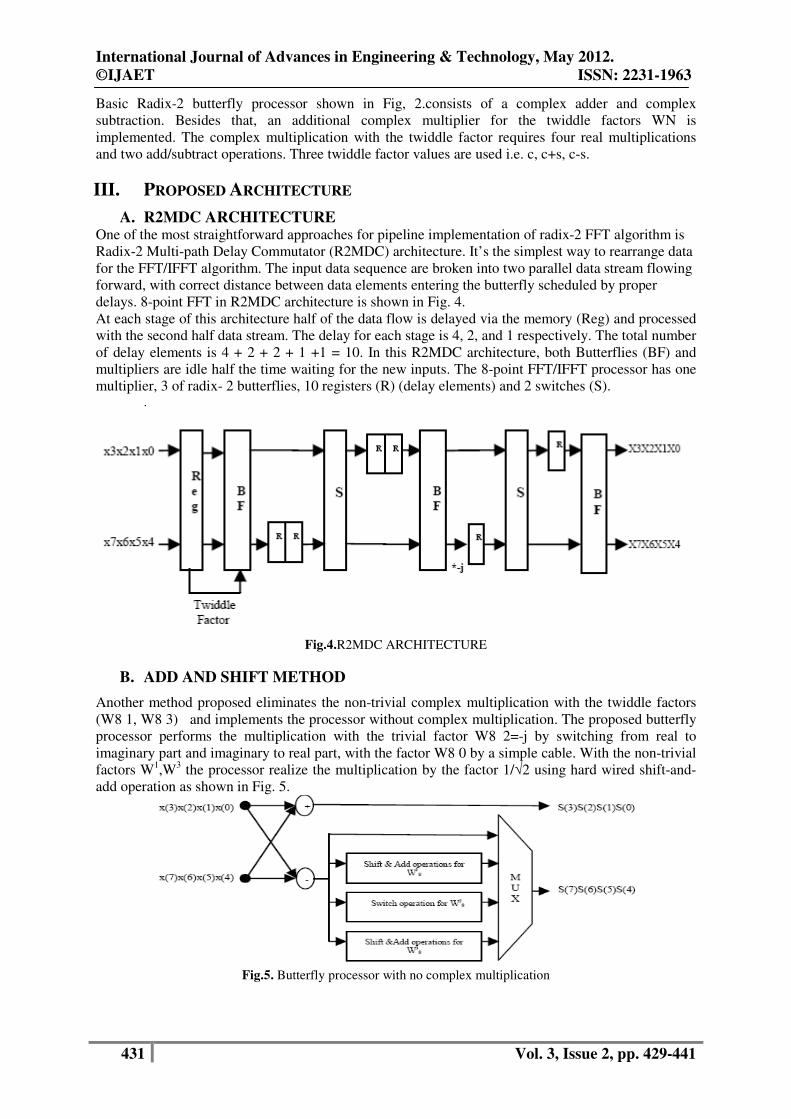
A. R2MDC ARCHITECTURE One of the most straightforward approaches for pipeline implementation of radix-2 FFT algorithm is
Radix-2 Multi-path Delay Commutator (R2MDC) architecture. It’s the simplest way to rearrange data
for the FFT/IFFT algorithm. The input data sequence are broken into two parallel data stream flowing
forward, with correct distance between data elements entering the butterfly scheduled by proper
delays. 8-point FFT in R2MDC architecture is shown in Fig. 4.
At each stage of this architecture half of the data flow is delayed via the memory (Reg) and processed
with the second half data stream. The delay for each stage is 4, 2, and 1 respectively. The total number
of delay elements is 4 + 2 + 2 + 1 +1 = 10. In this R2MDC architecture, both Butterflies (BF) and
multipliers are idle half the time waiting for the new inputs. The 8-point FFT/IFFT processor has one
multiplier, 3 of radix- 2 butterflies, 10 registers (R) (delay elements) and 2 switches (S). .
Fig.4.R2MDC ARCHITECTURE
B. ADD AND SHIFT METHOD
Another method proposed eliminates the non-trivial complex multiplication with the twiddle factors
(W8 1, W8 3) and implements the processor without complex multiplication. The proposed butterfly
processor performs the multiplication with the trivial factor W8 2=-j by switching from real to
imaginary part and imaginary to real part, with the factor W8 0 by a simple cable. With the non-trivial
factors W1,W
3 the processor realize the multiplication by the factor 1/√2 using hard wired shift-and-
add operation as shown in Fig. 5.
Fig.5. Butterfly processor with no complex multiplication

International Journal of Advances in Engineering & Technology, May 2012.
©IJAET ISSN: 2231-1963
432 Vol. 3, Issue 2, pp. 429-441
IV. ANALYSIS AND DESIGN OF FFT USING VHDL
A. Simulation methodology VHDL is language for describing digital electronic systems. It arose out of the United States
government’s very high speed integrated circuits (VHSIC) program, in the course of this program; it
became clear that there was a need for a standard language for describing the structure and function of
integrated circuits(IC’s). Hence the VHSIC hardware description language (VHDL) was developed.
Modeling for simulation and synthesis is a vital part of a range of levels of abstraction, from gate
levels up to algorithmic and architectural levels. It will continue to play an important role in the
design of silicon-based systems for some time to come. Very high speed integrated circuit hardware
description language (VHDL) can be used to model digital systems and introduce some of the basic
concepts underlying the language.
The ModelSim-Altera simulator compiles the testbench and the netlist (multiplier.vho), annotates the
SDF data (in multiplier_vhd.sdo), and runs the simulation for the specified time. A waveform
window within the ModelSim-Altera simulator is invoked that shows the expected and actual results
of the multiplier. The expected and actual results are also checked in the test bench, and messages that
show whether or not the results match are displayed in the simulator’s console window. The data
output of the multiplier module changes with a delay after the clock edge because the SDF data is
annotated in the gate-level timing simulation.
B. Simulation result
The simulation results are given below.
Fig.6. Simulation result of R2MDC architecture
This simulation shows the radix-2 operation. Two inputs are selected with the help of demultiplixer
which is present inside the buffer block. Addition and subtraction of two inputs with a twiddle factor
multiplication. It produces final fft output.
The VHDL Program is compiled in Model sim v6.4a to generate the butterfly processor operation
with the help of R2MDC architecture, Add and shift method to know the design functionality and for
power, area analysis Xilinx is used.

International Journal of Advances in Engineering & Technology, May 2012.
©IJAET ISSN: 2231-1963
433 Vol. 3, Issue 2, pp. 429-441
Fig.7. Simulation result of add and shift method
This simulation shows that the input after addition and subtraction of radix-2 process multiplied with
a real number of complex variable. It produces the same fft output.
V. POWER AND AREA ANALYSIS OF R2MDC AND ADD SHIFT METHOD
Table 1 Power Analysis ARCHITECTURE
SYNTHESIS POWER
MULTIPLICATION
R2MDC ARCHITECTURE
0.323 3
ADD SHIFT METHOD 1.517 0
Table 2 Area Analysis
Device Utilization Summary for Add shift method
Logic Utilization Used Available Utilization
Number of 4 input LUTs 148 3,840 3%
Logic Distribution
Number of occupied Slices 80 1,920 4%
Number of Slices containing only related logic 80 80 100%
Number of Slices containing unrelated logic 0 80 0%
Total Number of 4 input LUTs 157 3,840 4%
Number used as logic 148
Number used as a route-thru 9
Number of bonded IOBs 34 141 24%
With the simulation output a vcd file is created in the transcript of modelsim and it is
synthesis in Xilinx to show the power and area analysis for r2mdc and add shift method.
Device Utilization Summary for R2MDC
Logic Utilization Used Available Utilization
Number of Slice Latches 16 3,840 1%
Number of 4 input LUTs 85 3,840 2%
Logic Distribution
Number of occupied Slices 52 1,920 2%
Number of Slices containing only related logic 52 52 100%
Number of Slices containing unrelated logic 0 52 0%
Total Number of 4 input LUTs 87 3,840 2%

International Journal of Advances in Engineering & Technology, May 2012.
©IJAET ISSN: 2231-1963
434 Vol. 3, Issue 2, pp. 429-441
Number used as logic 85
Number used as a route-thru 2
Number of bonded IOBs 36 141 25%
Number of MULT18X18s 3 12 25%
VI. CONCLUSION
In this paper, two pipeline-based FFT Architectures are proposed. Our proposed variable-length FFT
processor that are suitable for various MIMO OFDM-based communication systems, such as IEEE
802.11n, and IEEE 802.16 WiMAX, can perform 256/128/64/16/8-point with 1-4 data sequences. The
proposed 8-point FFT processor is used for IEEE 802.11n, and the proposed 8-point FFT processor is
used for IEEE 802.11n and IEEE 802.16. To reduce computational complexity and increase hardware
utility, we adopt different radix FFT algorithms and multiple-path delay commutates FFT architecture
in our processors. The multiple-path delay commutator FFT architectures require fewer delay
elements and different radix FFT algorithms require fewer complex multiplications. The processor
Implementation are fabricated using UMC 0.18 m µ process and their area are 1.5162 2 mm and
2.5122 2 mm.
REFERENCES
[1]. .M.Arioua, S.Belkouch, M.M.Hassani, “Complex multiplication reduction in pipeline FFT
architecture,” In Proc. of 20th Intern. Conf. on Computer Theory and Applications (ICCTA),
Alexandria, Egypt, Oct. 2010
[2]. B.Wang, Q. Zhang, Tao, M.Huang, “Design of Pipelined FFT Processor Based on FPGA,” In Proc. of
the 2nd Intern. Conf. on Computer Modeling and Simulation (ICCMS’10), pp. 432-435, ISBN 978-1-
4244-5642-0, Jan. 2010, Sanya, Hainan
[3]. Design of COFDM Transceiver Using VHDL International Journal of Computer Applications (0975 –
8887) Volume 5– No.7, August 2010
[4]. FPGA Implementation of OFDM Transceiver for a 60GHz Wireless Mobile Radio System 2010
International Conference on Reconfigurable Computing
[5]. IEEE 802.15 WPAN Task Group 3c (TG3c) Millimeter Wave Alternative PHY Friday, 5 February
2010,
[6]. Hardware Implementation Low Power High Speed FFT Core The International Arab Journal of
Information Technology, Vol. 6, No. 1, January 2009
[7]. P.Verma, H. Kaur, M.Singh, M, B.Singh, “VHDL Implementation of FFT/IFFT Blocks for OFDM,”
In Proc. of Intern. Conf on Advances in Recent in Communication and Computing, pp. 186-188, PI.
978-1- 4244-5104-3 Kerala, 2009.
[8]. X. Jinsong, L. Xiaochun, W. Haitao, B. Yujing, Z. Decai, Z. Xiaolong, W. Chaogang, “Implementation
of MB-OFDM Transmitter Baseband Based on FPGA”, in 4th IEEE International Conference on
Circuits and Systems for Communications (ICCSC 2008), 2008, 26-28 May 2008
Appendix The program of R2mdc architecture
ADDER library ieee;
use ieee.std_logic_1164.all;
use ieee.std_logic_arith.all;
use ieee.std_logic_signed.all;
--use ieee.std_logic_math.all;
entity adder is
port(a,r:in std_logic_vector(3
downto 0);
c:out std_logic_vector(3
downto 0));
end entity;
architecture adder of adder is
--signal x:std_logic;
begin
process(a,r)
begin
c<=a+r;
end process;
--c<=x;

International Journal of Advances in Engineering & Technology, May 2012.
©IJAET ISSN: 2231-1963
435 Vol. 3, Issue 2, pp. 429-441
--end process;
end architecture;
BUTTERFLY
library ieee;
use ieee.std_logic_1164.all;
use ieee.std_logic_arith.all;
use ieee.std_logic_unsigned.all;
entity butterfly is
port(x1:in std_logic_vector(3
downto 0);
x2:in std_logic_vector(3
downto 0);
c1:in std_logic;
y1,y2:out std_logic_vector(3
downto 0));
end entity;
architecture butterfly of butterfly
is
component adder is
port(a,r:in std_logic_vector(3
downto 0);
c:out std_logic_vector(3
downto 0));
end component;
component subtractor is
port(a,s:in std_logic_vector(3
downto 0);
c:out std_logic_vector(3
downto 0));
end component;
component mux is
port(sel:in std_logic;
a:in std_logic_vector(3 downto
0);
b:in std_logic_vector(3 downto
0);
y:out std_logic_vector(3
downto 0));
end component;
signal s1,s2,s3,s4:std_logic_vector(3
downto 0);
signal o1,o2:std_logic_vector(3
downto 0);
signal z,q:std_logic_vector(3 downto
0);
begin
--p:process(x1,x2,c1)
--variable o1,o2,q:integer range 0 to
7;
--variable z:integer range 0 to 7:=7;
--variable s1,s2,s3,s4:integer range
0 to 7:=7;
--begin
u0:mux port
map(a=>x1,b=>s3,sel=>'0',y=>z);
u1:mux port
map(a=>x2,b=>s4,sel=>'0',y=>q);
u2:adder port map(a=>x1,r=>z,c=>s1);
u3:mux port
map(a=>z,b=>s1,sel=>c1,y=>y1);
u4:adder port map(a=>x2,r=>q,c=>s2);
u5:mux port
map(a=>q,b=>s2,sel=>c1,y=>y2);
u6:subtractor port
map(a=>z,s=>x1,c=>s3);
u7:mux port
map(a=>x1,b=>s3,sel=>c1,y=>o1);
u8:subtractor port
map(a=>q,s=>x2,c=>s4);
u9:mux port
map(a=>x2,b=>s4,sel=>c1,y=>o2);
--o1<=o1*00000010;
--o2<=o2*00000010;
--y1<=o1;
--y2<=o2;
--end process p;
--end;
end architecture;
DEMUX
library ieee;
use ieee.std_logic_1164.all;
entity demux is
port(i:in std_logic_vector(3 downto
0);
--s:in std_logic;
sel2:in std_logic_vector(1
downto 0);
y0:out std_logic_vector(3
downto 0);
y1:out std_logic_vector(3
downto 0));
end demux;
architecture Behavioral of demux is
--signal s:std_logic;
begin
process(i,sel2)
begin
case sel2 is
when "00" => y0 <= i;
when "11" => y1 <= i;
when others => --out0 <= bitin;
out0 <= '0'; out1 <= '0'; out2 <='0';
end case;
end process;

International Journal of Advances in Engineering & Technology, May 2012.
©IJAET ISSN: 2231-1963
436 Vol. 3, Issue 2, pp. 429-441
end Behavioral;
INTERBLOCK
library ieee;
use ieee.std_logic_1164.all;
use ieee.std_logic_arith.all;
use ieee.std_logic_unsigned.all;
--use ieee.std_logic_math.all;
entity interblock is
port(j,k: in std_logic_vector(3
downto 0);
sel:in std_logic;
y0:out std_logic_vector(3
downto 0);
y1:out std_logic_vector(3
downto 0));
end interblock;
architecture fft2 of interblock is
begin
process(j,k)
variable s:std_logic_vector(3
downto 0);
begin
s:="0001";
case sel is
when '0' =>
y0<=j+s;
when '1'=>
y1<=k;
when others =>
end case;
end process;
end architecture;
MULTIPLIER library ieee;
use ieee.std_logic_1164.all;
use ieee.std_logic_arith.all;
use ieee.std_logic_unsigned.all;
--use ieee.std_logic_math.all;
entity multi is
port(inp,w: in std_logic_vector(3
downto 0);
oup:out std_logic_vector(3
downto 0));
end multi;
architecture fft3 of multi is
signal sin:std_logic_vector(7
downto 0);
signal si:std_logic_vector(7 downto
0);
--signal k:std_logic_vector(7
downto 0);
begin
si<=inp*w;
sin<=si + b"0010";
oup<=sin(3 downto 0);
end fft3;
MULTIPLEXER
library ieee;
use ieee.std_logic_1164.all;
use ieee.std_logic_arith.all;
use ieee.std_logic_unsigned.all;
entity mux is
port(sel:in std_logic;
a:in std_logic_vector(3 downto
0);
b:in std_logic_vector(3 downto
0);
y:out std_logic_vector(3
downto 0));
end entity;
architecture mux of mux is
begin
process(a,b,sel)
begin
case sel is
when '0'=>
y<=a;
when others=>
y<=b;
end case;
end process;
end mux;
SUBTRACTOR
library ieee;
use ieee.std_logic_1164.all;
use ieee.std_logic_arith.all;
use ieee.std_logic_signed.all;
entity subtractor is
port(a,s:in std_logic_vector(3
downto 0);
c:out std_logic_vector(3
downto 0));
end entity;
architecture subtractor of subtractor
is
begin
process(a,s)
begin
c<=a-s;
end process;
end architecture;
TOP MODULE library ieee;
use ieee.std_logic_1164.all;
use ieee.std_logic_arith.all;
entity top_module is

International Journal of Advances in Engineering & Technology, May 2012.
©IJAET ISSN: 2231-1963
437 Vol. 3, Issue 2, pp. 429-441
port(a:in std_logic_vector(3 downto
0);
selall:in std_logic_vector(3
downto 0);
an:in std_logic;
bfsel:in std_logic;
muxsel:in std_logic_vector(1
downto 0);
b1,b2:out std_logic_vector(3
downto 0));
end entity;
architecture top_module of top_module
is
component demux is
port(i: in std_logic_vector(3
downto 0);
sel2:in std_logic_vector(1
downto 0);
y0:out std_logic_vector(3
downto 0);
y1:out std_logic_vector(3
downto 0));
end component;
component butterfly is
port(x1,x2:in std_logic_vector(3
downto 0);
c1:in std_logic;
y1,y2:out std_logic_vector(3
downto 0));
end component;
component multi is
port(inp,w: in std_logic_vector(3
downto 0);
oup:out std_logic_vector(3
downto 0));
end component;
component interblock is
port(j,k: in std_logic_vector(3
downto 0);
sel:in std_logic;
y0:out std_logic_vector(3
downto 0);
y1:out std_logic_vector(3
downto 0));
end component;
signal
s1,s2,s8,s9,s10,s11,s12,s13,s14,s15,s
16,s17,s18,s19:std_logic_vector(3
downto 0);
--signal n1,n2,n3:std_logic;
begin
u1:demux port
map(i=>a,sel2=>muxsel,y0=>s1,y1=>s2);
--u2:butterfly port
map(x1=>s1,x2=>s2,c1=>bfsel,y1=>s3,y2
=>s4);
--u3:multi port
map(inp=>s4,w=>selall,oup=>s5);
--u4:interblock port
map(j=>s3,k=>s5,sel=>an,y0=>s6,y1=>s7
);
u5:butterfly port
map(x1=>s1,x2=>s2,c1=>bfsel,y1=>s8,y2
=>s9);
u6:multi port
map(inp=>s9,oup=>s10,w=>selall);
u7:interblock port
map(j=>s8,k=>s10,sel=>an,y0=>s11,y1=>
s12);
u8:butterfly port
map(x1=>s11,x2=>s12,c1=>bfsel,y1=>s13
,y2=>s14);
u9:multi port
map(inp=>s14,oup=>s15,w=>selall);
u10:interblock port
map(j=>s13,k=>s15,sel=>an,y0=>s16,y1=
>s17);
u11:butterfly port
map(x1=>s16,x2=>s17,c1=>bfsel,y1=>s18
,y2=>s19);
b1<=s18;
b2<=s19;
end architecture;
The program for add and shift method
library ieee;
use ieee.std_logic_1164.all;
entity append is
port(a:in std_logic_vector(21
downto 0);
c:out std_logic_vector(22 downto
0));
end entity;
architecture beh of append is
begin
process(a)
begin
c<=('0'&a);
end process;
end;
library ieee;
use ieee.std_logic_1164.all;
use ieee.std_logic_unsigned.all;
entity mux2 is
port(inp1,inp2:in
std_logic_vector(7 downto 0);
s:in std_logic;
outp:out std_logic_vector(7
downto 0));
end entity;
architecture beh of mux2 is
begin
International Journal of Advances in Engineering & Technology, May 2012.
©IJAET ISSN: 2231-1963
438 Vol. 3, Issue 2, pp. 429-441
process(inp1,inp2,s)
begin
case(s) is
when '0'=>
outp<=inp1;
when '1'=>
outp<=inp2;
when others=>
null;
end case;
end process;
end;
library ieee;
use ieee.std_logic_1164.all;
entity inv is
port(a:in std_logic_vector(21
downto 0);
c:out std_logic_vector(22 downto
0));
end entity;
architecture beh of inv is
signal d:std_logic_vector(21
downto 0);
begin
process(a)
begin
d<=(not a);
end process;
c<=('0'&d);
end;
library ieee;
use ieee.std_logic_1164.all;
use ieee.std_logic_unsigned.all;
entity mux4 is
port(a,b,c,d:in
std_logic_vector(22 downto 0);
s:in std_logic_vector(1
downto 0);
outp:out std_logic_vector(22
downto 0));
end entity;
architecture beh of mux4 is
begin
process(a,b,s)
begin
case(s) is
when "00"=>
outp<=a;
when "01"=>
outp<=b;
when "10"=>
outp<=c;
when "11"=>
outp<=d;
when others=>
null;
end case;
end process;
end;
library ieee;
use ieee.std_logic_1164.all;
use ieee.std_logic_unsigned.all;
entity shift2 is
port(inp:in std_logic_vector(7
downto 0);
outp:out std_logic_vector(22
downto 0));
end entity;
architecture beh of shift2 is
signal x1,x2:std_logic_vector(9
downto 0);
signal x3,x4:std_logic_vector(13
downto 0);
signal x5:std_logic_vector(22
downto 0);
signal x6:std_logic_vector(18
downto 0);
signal x7:std_logic_vector(22
downto 0);
begin
process(inp,x1,x2,x3,x4,x5,x6,x7)
begin
x1<=(inp & "00");
x2<=x1+inp;
x3<=(inp & "000000");
x4<=x3+inp;
x5<=(inp &
"000000000000000");
x6<=(x2 &
"000000000");
x7<=x5-x6;
outp<=x7+x4;
end process;
end;
library ieee;
use ieee.std_logic_1164.all;
use ieee.std_logic_unsigned.all;
entity swap is
port(inp1,inp2:in
std_logic_vector(22 downto 0);
outp1,outp2:out
std_logic_vector(22 downto 0));
end entity;
architecture beh of swap is
begin
process(inp1,inp2)
begin
outp1<=inp2;
outp2<=inp1;
end process;
end;

International Journal of Advances in Engineering & Technology, May 2012.
©IJAET ISSN: 2231-1963
439 Vol. 3, Issue 2, pp. 429-441
library ieee;
use ieee.std_logic_1164.all;
use ieee.std_logic_unsigned.all;
use ieee.std_logic_arith.all;
entity cse is
port(a:in std_logic_vector(7
downto 0);
c,d:out
std_logic_vector(7 downto 0));
end entity;
architecture beh of cse is
signal
s1,s2:std_logic_vector(7 downto 0);
begin
process(a)
begin
s1<=("00" & a(7 downto
2));
s2<=("000000" & a(7
downto 6));
end process;
c<=a + s1;
d<=a + s2;
end;
library ieee;
use ieee.std_logic_1164.all;
entity inv1 is
port(a:in std_logic_vector(22
downto 0);
c:out std_logic_vector(22 downto
0));
end entity;
architecture beh of inv1 is
begin
process(a)
begin
c<=(not a);
end process;
end;
library ieee;
use ieee.std_logic_1164.all;
use ieee.std_logic_unsigned.all;
entity shift1 is
port(inp:in std_logic_vector(7
downto 0);
outp:out std_logic_vector(21
downto 0));
end entity;
architecture beh of shift1 is
signal x1,x2:std_logic_vector(9
downto 0);
signal x3,x4:std_logic_vector(13
downto 0);
signal x5:std_logic_vector(21
downto 0);
signal x6:std_logic_vector(18
downto 0);
signal x7:std_logic_vector(14
downto 0);
begin
process(inp,x1,x2,x3,x4,x5,x6,x7)
begin
x1<=(inp & "00");
x2<=x1+inp;
x3<=(inp & "000000");
x4<=x3+inp;
x5<=(x2 &
"000000000000");
x6<=(x2 &
"000000000");
x7<=(x4 & '0');
outp<=x5+x6+x7;
end process;
end;
library ieee;
use ieee.std_logic_1164.all;
use ieee.std_logic_unsigned.all;
entity shift3 is
port(inp:in std_logic_vector(7
downto 0);
outp:out std_logic_vector(21
downto 0));
end entity;
architecture beh of shift3 is
signal x1,x2:std_logic_vector(9
downto 0);
signal x3,x4:std_logic_vector(13
downto 0);
signal x5:std_logic_vector(19
downto 0);
signal x6:std_logic_vector(19
downto 0);
signal x7:std_logic_vector(21
downto 0);
begin
process(inp,x1,x2,x3,x4,x5,x6,x7)
begin
x1<=(inp & "00");
x2<=x1+inp;
x3<=(inp & "000000");
x4<=x3+inp;
x5<=(inp &
"000000000000");
x6<=x5+x2;
x7<=(x4 &
"00000000");
outp<=x7-x6;
end process;
end;
library ieee;
use ieee.std_logic_1164.all;
use ieee.std_logic_unsigned.all;
entity top is
port(inp:in std_logic_vector(7
downto 0);
sel1:in std_logic;
sel2:in std_logic_vector(1

International Journal of Advances in Engineering & Technology, May 2012.
©IJAET ISSN: 2231-1963
440 Vol. 3, Issue 2, pp. 429-441
downto 0);
outp:out std_logic_vector(22
downto 0));
end entity;
architecture beh of top is
component cse is
port(a:in std_logic_vector(7
downto 0);
c,d:out
std_logic_vector(7 downto 0));
end component;
component mux is
port(a,b:in std_logic_vector(22
downto 0);
s:in std_logic;
outp:out std_logic_vector(22
downto 0));
end component;
component shift1 is
port(inp:in std_logic_vector(7
downto 0);
outp:out std_logic_vector(21
downto 0));
end component;
component shift2 is
port(inp:in std_logic_vector(7
downto 0);
outp:out std_logic_vector(22
downto 0));
end component;
component shift3 is
port(inp:in std_logic_vector(7
downto 0);
outp:out std_logic_vector(21
downto 0));
end component;
component inv is
port(a:in std_logic_vector(21
downto 0);
c:out std_logic_vector(22 downto
0));
end component;
component inv1 is
port(a:in std_logic_vector(22
downto 0);
c:out std_logic_vector(22 downto
0));
end component;
component append is
port(a:in std_logic_vector(21
downto 0);
c:out std_logic_vector(22 downto
0));
end component;
component swap is
port(inp1,inp2:in
std_logic_vector(22 downto 0);
outp1,outp2:out
std_logic_vector(22 downto 0));
end component;
component mux2 is
port(inp1,inp2:in
std_logic_vector(7 downto 0);
s:in std_logic;
outp:out std_logic_vector(7
downto 0));
end component;
component mux4 is
port(a,b,c,d:in
std_logic_vector(22 downto 0);
s:in std_logic_vector(1
downto 0);
outp:out std_logic_vector(22
downto 0));
end component;
signal
s1,s2,s3:std_logic_vector(7 downto
0);
signal r1,r2:std_logic_vector(21
downto 0);
signal
t1,inve1,inve2,inve3,inve4:std_logic_
vector(22 downto 0);
signal
m1,m2,m3:std_logic_vector(22 downto
0);
begin
i0:cse port map(inp,s1,s2);
i1:mux2 port
map(s1,s2,sel1,s3);
i2:shift1 port map(s3,r1);
i3:shift2 port map(s3,t1);
i4:shift3 port map(s3,r2);
i5:inv port map(r1,inve1);
i6:inv port map(r2,inve4);
i7:inv1 port map(t1,inve3);
i8:append port map(r1,inve2);
i9:mux port
map(inve1,inve2,sel1,m1);
i10:swap port
map(inve3,inve4,m2,m3);
i11:mux4 port
map(inve1,m1,m2,m3,sel2,outp);
end;

International Journal of Advances in Engineering & Technology, May 2012.
©IJAET ISSN: 2231-1963
441 Vol. 3, Issue 2, pp. 429-441
Author Biography M. Pradeepa was born in Coimbatore in 1987. I complete B.E. Degree in Electronics and
communication from Tamilnadu college of engineering, Coimbatore. Currently I am doing
M.E. in VLSI Design in SNSCT. I develop this paper as my final year project. I am interested
to develop a communication system with the help of VLSI technology. Later I like to expand
this paper for complete data transmission modem.