optimized frp wrapping schemes for circular concrete
TRANSCRIPT

University of Wollongong University of Wollongong
Research Online Research Online
Faculty of Engineering and Information Sciences - Papers: Part A
Faculty of Engineering and Information Sciences
1-1-2015
Optimized FRP wrapping schemes for circular concrete columns under Optimized FRP wrapping schemes for circular concrete columns under
axial compression axial compression
Thong M. Pham University of Wollongong, [email protected]
Muhammad N. S Hadi University of Wollongong, [email protected]
Jim Youssef University of Wollongong, [email protected]
Follow this and additional works at: https://ro.uow.edu.au/eispapers
Part of the Engineering Commons, and the Science and Technology Studies Commons
Recommended Citation Recommended Citation Pham, Thong M.; Hadi, Muhammad N. S; and Youssef, Jim, "Optimized FRP wrapping schemes for circular concrete columns under axial compression" (2015). Faculty of Engineering and Information Sciences - Papers: Part A. 4774. https://ro.uow.edu.au/eispapers/4774
Research Online is the open access institutional repository for the University of Wollongong. For further information contact the UOW Library: [email protected]

Optimized FRP wrapping schemes for circular concrete columns under axial Optimized FRP wrapping schemes for circular concrete columns under axial compression compression
Abstract Abstract This study investigates the behavior and failure modes of FRP confined concrete wrapped with different FRP schemes, including fully wrapped, partially wrapped and non-uniformly wrapped concrete cylinders. By using the same amount of FRP, this study proposes a new wrapping scheme that provides a higher compressive strength and strain for FRP-confined concrete, in comparison with conventional fully wrapping schemes. A total of thirty three specimens were cast and tested, with three of these specimens acting as reference specimens and the remaining specimens wrapped with different types of FRP (CFRP and GFRP) by different wrapping schemes. For specimens that belong to the descending branch type, the partially wrapped specimens had a lower compressive strength but a higher axial strain as compared to the corresponding fully wrapped specimens. In addition, the non-uniformly wrapped specimens achieved both a higher compressive strength and axial strain in comparison with the fully wrapped specimens. Furthermore, the partially wrapping scheme changes the failure modes of the specimens and the angle of the failure surface. A new equation that can be used to predict the axial strain of concrete cylinders wrapped partially with FRP is proposed.
Disciplines Disciplines Engineering | Science and Technology Studies
Publication Details Publication Details Pham, T. M., Hadi, M. N. S. & Youssef, J. (2015). Optimized FRP wrapping schemes for circular concrete columns under axial compression. Journal of Composites for Construction, 19 (6), 04015015-1-04015015-10.
This journal article is available at Research Online: https://ro.uow.edu.au/eispapers/4774

1
Optimized FRP Wrapping Schemes for Circular Concrete Columns under 1
Axial Compression 2
Thong M. Pham A.M.ASCE1, Muhammad N.S. Hadi, F.ASCE2 and Jim Youssef3 3
Abstract 4
This study investigates the behavior and failure modes of FRP confined concrete wrapped 5
with different FRP schemes, including fully wrapped, partially wrapped and non-uniformly 6
wrapped concrete cylinders. By using the same amount of FRP, this study proposes a new 7
wrapping scheme that provides a higher compressive strength and strain for FRP-confined 8
concrete, in comparison with conventional fully wrapping schemes. A total of thirty three 9
specimens were cast and tested, with three of these specimens acting as reference specimens 10
and the remaining specimens wrapped with different types of FRP (CFRP and GFRP) by 11
different wrapping schemes. For specimens that belong to the descending branch type, the 12
partially wrapped specimens had a lower compressive strength but a higher axial strain as 13
compared to the corresponding fully wrapped specimens. In addition, the non-uniformly 14
wrapped specimens achieved both a higher compressive strength and axial strain in 15
comparison with the fully wrapped specimens. Furthermore, the partially wrapping scheme 16
changes the failure modes of the specimens and the angle of the failure surface. A new 17
equation that can be used to predict the axial strain of concrete cylinders wrapped partially 18
with FRP is proposed. 19
CE Database subject headings: Fiber Reinforced Polymer; Confinement; Concrete columns; 20
Strain; Stress-strain relation; Concrete; Cylinders. 21 1Postdoctoral Research Associate, School of Civil and Mechanical Engineering, Curtin University, Kent Street, Bentley, WA 6102, Australia; Formerly, PhD Scholar, School of Civil, Mining and Environmental Engineering, University of Wollongong, Wollongong, NSW 2522, Australia. Email: [email protected] 2Associate Professor, School of Civil, Mining and Environmental Engineering, University of Wollongong, Wollongong, NSW 2522, Australia (corresponding author). Email: [email protected] 3Ph.D. Candidate, School of Civil, Mining and Environmental Engineering, University of Wollongong, Wollongong, NSW 2522, Australia. Email: [email protected]

2
Introduction 22
Fiber Reinforced Polymer (FRP) has been commonly used to strengthen existing reinforced 23
concrete (RC) columns in recent years. In such cases, FRP is a confining material for concrete 24
in which the confinement effect leads to increase in the strength and ductility of columns. In 25
early experimental studies that focused on retrofitting RC columns with FRP, the columns 26
were usually wrapped fully with FRP sheets. This wrapping scheme provides continuous 27
confinement to the columns along their longitudinal axes. Most of the studies in the literature 28
focus only on columns fully wrapped with FRP (Chaallal et al. 2003; Hadi et al. 2013; Pham 29
et al. 2013; Pham and Hadi 2014a; Smith et al. 2010). In addition, columns wrapped partially 30
with FRP have also been proven to show increases in strength and ductility, as compared to 31
equivalent unconfined columns (Colomb et al. 2008; Maaddawy 2009; Turgay et al. 2010). 32
However, there is no study that makes a comparison of the confinement efficacy between 33
partially and fully wrapping schemes in terms of optimization of the FRP amount. In addition, 34
the progressive failure of those specimens has not been extensively studied. Therefore, it is 35
necessary to investigate the confinement efficacy and failure mechanisms of columns partially 36
wrapped versus columns fully wrapped with FRP. 37
In addition, the available design guidelines for columns wrapped with FRP (ACI 440.2R-08 38
2008; fib 2001; TR 55 2012) are utilized to estimate the capacities of partially FRP-wrapped 39
specimens. Among these studies, ACI-440.2R (2008) and technical report TR 55 (2012) do 40
not provide information about the confinement effect of concrete columns partially wrapped 41
with FRP. Meanwhile, fib (2001) suggests a reduction factor to take into account the effect of 42
partial wrapping columns. The study by fib (2001) adopts an assumption proposed by Mander 43
et al. (1988) for the confinement effect of steel ties in RC columns to analyze the efficacy of 44
FRP partially wrapped columns. Therefore, there has been a lack of theoretical and 45

3
experimental works about partial FRP-confined concrete. For this reason, an experimental 46
program was developed in this study to compare the confinement efficacy of FRP partially 47
wrapped columns as compared to FRP fully wrapped columns. The same amount of FRP was 48
wrapped onto identical concrete columns by different wrapping schemes to achieve an 49
optimized wrapping design. 50
Confinement Mechanism 51
Fully Wrapped Columns 52
In the literature, the term “FRP confined concrete” is understood automatically as concrete 53
wrapped fully with FRP. When a circular concrete column is horizontally wrapped with FRP 54
around its perimeter, the whole column is confined by the lateral pressure exerted from the 55
FRP jackets as shown in Fig. 1a. Many studies have been carried out to investigate the 56
behaviors and estimate the capacities of columns wrapped fully with FRP (De Luca and 57
Nanni 2011; Lam and Teng 2003; Pham and Hadi 2014b; Pham and Hadi 2014c; Teng et al. 58
2009; Toutanji 1999; Wu and Zhou 2010). The confining pressure is assumed to be uniform 59
in the cross section and along the axial axis of the circular columns. Among the existing 60
studies, the model proposed by Lam and Teng (2003) is adopted in this study to calculate the 61
compressive strength for columns wrapped fully with FRP as follows: 62
'co
l'
co
'cc
f
f.
f
f331
(1) 63
where fcc’ and fco
’ are respectively the compressive strength of confined concrete and 64
unconfined concrete, and fl is the effective confining pressure as follows: 65
D
tEf fef
l
2 (2) 66

4
where Ef is the elastic modulus of FRP, t is the nominal thickness of FRP jacket, D is the 67
diameter of the column section, and fe is the actual rupture strain of FRP in the hoop 68
direction. The model by Lam and Teng (2003) is chosen because it provides a reasonable 69
accuracy with a very simple form. The simplicity of the model by Lam and Teng (2003) is 70
utilized to establish a new and simple strain model, which is presented in the sections below. 71
The strain model proposed by Pham and Hadi (2013) is adopted to calculate the compressive 72
axial strain of confined concrete as follows: 73
fe'
co
fefecocc tf.Df
ktf
33
2
(3) 74
where cc is the ultimate axial strain of confined concrete,co is the axial strain at the peak 75
stress of unconfined concrete, k = 7.6 is the proportion factor, and ffe is the actual rupture 76
strength of FRP. 77
Partially Wrapped Columns 78
As mentioned above, concrete columns wrapped partially with FRP have been experimentally 79
verified to increase their strength and ductility. Concrete columns partially wrapped with FRP 80
are less efficient in nature than fully wrapped columns as both confined and unconfined zones 81
exist (Fig. 1b). An approach similar to the one proposed by Sheikh and Uzumeri (1980) is 82
adopted to determine the effective confining pressure on the concrete core. The effective 83
confining pressure is assumed to be exerted effectively on the part of the concrete core where 84
the confining pressure has fully developed due to the arching action as shown in Fig. 1b. The 85
arching effect is assumed to be described by a second-degree parabola with initial slope of 86
450. In such a case, a confinement effective coefficient (ke) is introduced to take the partial 87
wrapping into account as follows: 88

5
2
21
D
s
A
Ak
c
ee
(4) 89
where Ae and Ac are respectively the area of effectively confined concrete core and the cross-90
sectional area, and s is the clear spacing between two FRP bands. Consequently, the 91
compressive strength of concrete columns wrapped partially with FRP could be calculated as: 92
'co
'l
e'co
'cc
f
fk.
f
f331
(5) 93
Where ke is estimated based on Eq. 4 and fl’ shown in the following equation is the equivalent 94
confining pressure from the FRP, assumed to be uniformly distributed along the longitudinal 95
axis of the column. 96
sw
w
D
tEf fef'
l
2 (6) 97
where w is the width of FRP bands and s is the clear spacing between FRP bands as shown in 98
Fig. 1b. 99
Experimental Program 100
Design of Experiments 101
A total of thirty three FRP confined concrete cylinders were cast and tested at the High Bay 102
Laboratory of the University of Wollongong. The dimensions of the concrete cylinder 103
specimens were 150 mm in diameter and 300 mm in height. All the specimens were cast from 104
the same batch of concrete. The 28 day cylinder compressive strength was 52 MPa. 105
The experimental program was composed of several groups of cylinders in order to evaluate 106
the confinement efficacy between partially and fully wrapping schemes in terms of 107
optimization of the wrapping schemes. The notation of the specimens consists of three parts: 108
the first part states the type of confining FRP material, with “G” and “C” representing GFRP 109
and CFRP respectively. The second part is either a letter “R”, “F”, and “P” stating the name 110

6
of the sub-group, namely, reference group (R), fully wrapped group (F) and partially wrapped 111
group (P). The last part of the specimen notation is a number which indicates the number of 112
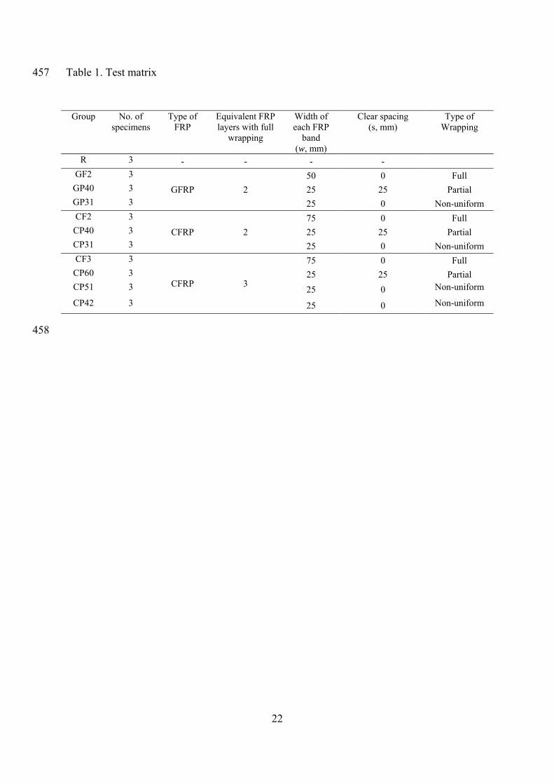
FRP layers. Details of the specimens are presented in Table 1. 113
The partially wrapped specimens contain FRP bands which are 25 mm in width spaced evenly 114
along the height of the specimen. The optimized partially wrapped specimens include two 115
numbers in the notation, for example GP31. The first number indicates the number of 25 mm 116
evenly spaced partial FRP layers and the second number depicts the number of FRP layers in 117
between these evenly spaced partial layers. These specimens were designed such that they 118
follow a non-uniform wrapping configuration but ensure the specimen is fully confined at 119
every location. The thicker band is called a tie band and the thinner band is called a cover 120
band. Taking specimen GP31 as an example, the tie bands have three FRP layers which are 25 121
mm in width, while the cover bands have one FRP layer as shown in Figure 2. Three identical 122
specimens were made for each wrapping scheme. 123
In order to analyze the confinement effectiveness between different wrapping schemes, the 124
specimens were divided in four groups (as shown in Table 1) such that the specimens in each 125
group incorporate the same amount of FRP but in a different wrapping scheme, either fully, 126
partially or optimized non-uniformly wrapped. The specimens in the first group are reference 127
specimens which did not include any internal or external reinforcement. The specimens in the 128
second and third groups were confined by GFRP and CFRP respectively, such that the fully, 129
partially and optimized non-uniform wrapping schemes were equivalent to two layers of full 130
wrapping. Similarly, the wrapping schemes of the specimens in the fourth group were 131
equivalent to three layers of full wrapping. 132
After 28 days, the specimens were wrapped with a number of FRP layers as shown in Table 1. 133
The adhesive used was a mixture of epoxy resin and hardener at 5:1 ratio. Before the first 134

7
layer of FRP was attached, the adhesive was spread onto the surface of the specimen and 135
CFRP was attached onto the surface with the main fibers oriented in the hoop direction. After 136
the first layer, the adhesive was spread onto the surface of the first layer of FRP and the 137
second layer was continuously bonded. The third layer of FRP was applied in a similar 138
manner, ensuring that 100 mm overlap was maintained. The ends of each wrapped specimen 139
were strengthened with additional one layer of FRP strips 25 mm in width. 140
Instrumentation 141
In order to measure the hoop strains of the FRP jacket, three strain gages with a gage length 142
of 5 mm were attached at the mid height of the specimens and evenly distributed away from 143
the overlap for the fully wrapped specimens. In the partially wrapped specimens, three strain 144
gages were bonded symmetrically on a tie band and other three were bonded on a cover band 145
at midheight of the specimen. 146
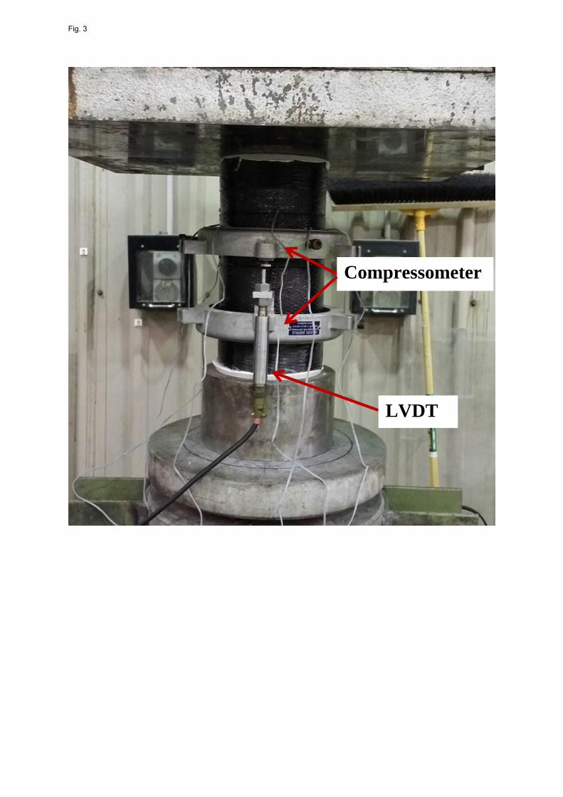
Furthermore, a longitudinal compressometer as shown in Fig. 3 was used to measure the axial 147
strain of the specimens. A Linear variable differential transformer (LVDT) was mounted on 148
the upper ring and the tip of the LVDT rests on an anvil. The readability, the accuracy, and 149
the repeatability of the LVDT complies with the Australian standard (Australian Standard-150
1545 1976). 151
The compression tests for all the specimens were conducted using the Denison 5000 kN 152
capacity testing machine. The specimens were capped with high strength plaster to ensure full 153
contact between the loading plate and the specimen. Calibration was carried out to ensure that 154
the specimens were placed at the center of the testing machine. Each specimen was first 155
loaded to around 30% of its unconfined capacity to check the alignment. If required, the 156
specimen was unloaded, realigned, and loaded again. The tests were conducted as deflection 157

8
controlled with a rate of 0.5 mm/min. The readings of the load, LVDT and strain gages were 158
taken using a data logging system and were subsequently saved in a control computer. 159
Experimental Results 160
Preliminary tests 161
The actual compressive strength of unconfined concrete calculated from three reference 162
specimens (R1, R2, and R3) was 54 MPa. The axial strain of unconfined concrete at the 163
maximum load was 0.23 %. In this study two types of CFRP were used to confine the 164
concrete, which both had a unidirectional fiber density of 340 g/m2 and a nominal thickness of 165
0.45 mm, but with varying nominal widths of 75 mm and 25 mm. The GFRP utilized had a 166
unidirectional fiber density of 440 g/m2, a nominal thickness of 0.35 mm and a nominal width 167
of 50 mm. 168
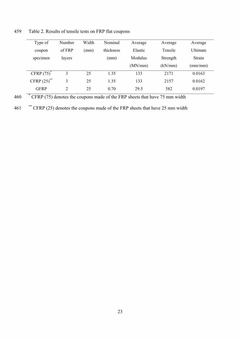
Five coupons for each type of FRP were made according to ASTM D7565 (2010) and tested 169
to determine the mechanical properties. The two types of CFRP coupons were made of three 170
layers of FRP with a nominal thickness of 1.35 mm and both types had very similar properties 171
as shown in Table 2. For simplicity the coupons produced from the 75 mm tape are denoted 172
by CFRP (75) while the coupons from the 25 mm tape are referred to as CFRP (25). For 173
GFRP, two-layered coupons containing two overlapping fiber sheets were prepared and 174
tested. The nominal thickness of the coupons was 0.7 mm. All coupons had the dimensions 25 175
mm x 250 mm. The epoxy resin had 54 MPa tensile strength, 2.8 GPa tensile modulus and 176
3.4% tensile elongation (West System n.d. 2015). 177
Failure Modes 178
All specimens were tested until failure. The specimens wrapped fully with FRP (CF2, CF3, 179
and GF2) failed by rupture of FRP at the midheight. The failure surface of the fully wrapped 180

9
specimens was found to be approximately 45 degree inclined, as shown in Fig. 4a. 181
Meanwhile, the partially wrapped specimens (CP40, CP60, and GP40) showed many small 182
cracks on the concrete surface at a stress equal to the unconfined concrete strength, as shown 183
in Fig. 4b. The concrete between the FRP bands, close to the outer surface of the specimen, 184
started crushing while the concrete core was still confined by the FRP. Cracks on the concrete 185
surface developed as the applied load increased, as shown in Fig. 4c. At the very high stress 186
level, the concrete between the FRP bands spalled off while the concrete under the FRP bands 187
and the core were still confined. These specimens then failed explosively by FRP rupture at 188
the midheight (Fig. 4d). 189
The angle of the failure surface with respect to the horizon for the partially wrapped 190
specimens was significantly different from the fully wrapping specimens. As shown in Fig. 191
4d, the failure surface took place at the spacing between FRP bands. This change of the 192
failure surface depends on the wrapping schemes and the stiffness of the FRP bands. When 193
the axial stress of the confined concrete was higher than the unconfined concrete strength, the 194
45 degree failure surface may have originally transpired in the concrete cores, but cracks were 195
arrested by FRP bands under the high stress stage. If the stiffness of the FRP bands is not 196
strong enough (Specimen GP40) to prevent the development of the cracks, the failure surface 197
takes place at approximately 45 degrees as shown in Fig. 4e. In contrast, the stiffness of the 198
FRP bands in Specimens CP40 and CP60 is great enough so that it changed the failure surface 199
as depicted in Fig. 4d. It is worth mentioning that the stiffness of the FRP bands affects the 200
tangent modulus of FRP-confined concrete. Tamuzs et al. (2008) suggested that the low value 201
of the tangent modulus causes column stability collapse directly as the unconfined concrete 202
strength level is surpassed. 203

10
Furthermore, specimens with optimized non-uniform wrapping schemes showed a different 204
failure mode as compared to the others. At a stress level equal to the unconfined concrete 205
strength, the concrete was still confined by the FRP tie bands and cover bands. During the 206
loading process, the lateral strains of the tie bands and the cover bands were almost identical, 207
with the exception of Specimen CP40_3. The failure modes of these specimens are similar to 208
those of the full wrapping specimens. The Non-uniform wrapped specimens failed by FRP 209
rupture simultaneously at the two bands (tie band and cover band) at the midheight, as shown 210
in Fig. 4f. It is worth mentioning that intermittent confinement resulted from partial 211
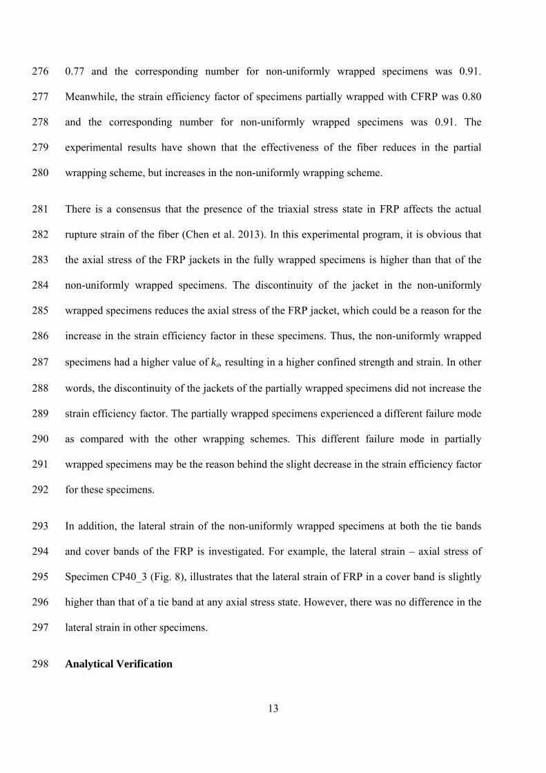
confinement (Specimens GP40, CP40, and CP60) makes the concrete to communicate 212
directly with the surroundings, for instance moisture, heat, and evaporation. 213
Stress-Strain Relation 214
Stress-strain relations of the tested specimens were divided into two main types based on the 215
shape of the stress-strain curves. These included specimens in the ascending branch type and 216
descending branch type. A FRP confined concrete column exhibits the ascending type curve 217
as a significant improvement of the compressive strength and strain of a FRP confined 218
concrete column could be expected. Otherwise, FRP confined concrete with a stress-strain 219
curve of the descending type illustrates a concrete stress at the ultimate strain below the 220
compressive strength of unconfined concrete. Specimens wrapped with glass fiber are 221
designed to behave as the descending branch type while specimens wrapped with carbon fiber 222
belong to the ascending branch type. Details of all tested specimens are summarized in Table 223
3. 224
Stress-strain relations of specimens wrapped by equivalent two GFRP layers were plotted in 225
Fig. 5. The specimens which were wrapped with an equivalent of two layers of FRP had 226
identical stress-strain curves at the early stages of loading and experienced slight differences 227
11
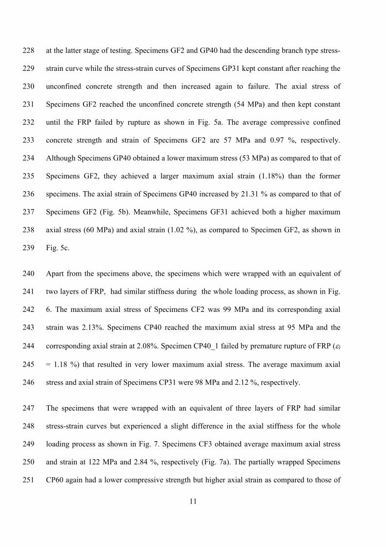
at the latter stage of testing. Specimens GF2 and GP40 had the descending branch type stress-228
strain curve while the stress-strain curves of Specimens GP31 kept constant after reaching the 229
unconfined concrete strength and then increased again to failure. The axial stress of 230
Specimens GF2 reached the unconfined concrete strength (54 MPa) and then kept constant 231
until the FRP failed by rupture as shown in Fig. 5a. The average compressive confined 232
concrete strength and strain of Specimens GF2 are 57 MPa and 0.97 %, respectively. 233
Although Specimens GP40 obtained a lower maximum stress (53 MPa) as compared to that of 234
Specimens GF2, they achieved a larger maximum axial strain (1.18%) than the former 235
specimens. The axial strain of Specimens GP40 increased by 21.31 % as compared to that of 236
Specimens GF2 (Fig. 5b). Meanwhile, Specimens GF31 achieved both a higher maximum 237
axial stress (60 MPa) and axial strain (1.02 %), as compared to Specimen GF2, as shown in 238
Fig. 5c. 239
Apart from the specimens above, the specimens which were wrapped with an equivalent of 240
two layers of FRP, had similar stiffness during the whole loading process, as shown in Fig. 241
6. The maximum axial stress of Specimens CF2 was 99 MPa and its corresponding axial 242
strain was 2.13%. Specimens CP40 reached the maximum axial stress at 95 MPa and the 243
corresponding axial strain at 2.08%. Specimen CP40_1 failed by premature rupture of FRP (l 244
= 1.18 %) that resulted in very lower maximum axial stress. The average maximum axial 245
stress and axial strain of Specimens CP31 were 98 MPa and 2.12 %, respectively. 246
The specimens that were wrapped with an equivalent of three layers of FRP had similar 247
stress-strain curves but experienced a slight difference in the axial stiffness for the whole 248
loading process as shown in Fig. 7. Specimens CF3 obtained average maximum axial stress 249
and strain at 122 MPa and 2.84 %, respectively (Fig. 7a). The partially wrapped Specimens 250
CP60 again had a lower compressive strength but higher axial strain as compared to those of 251

12
Specimens CF3. As shown in Fig. 7b, Specimens CP60 failed at the average compressive 252
strength of 116 MPa and axial strain of 3.25 %. The axial strain for the specimens CP60 253
increased by 14.33% in comparison with the Specimens CF3. As compared to Specimens 254
CF3, the non-uniformly wrapped Specimens CP42 had both higher compressive strength and 255
axial strain. Fig. 7d shows that Specimens CP42 failed at the average compressive strength of 256
128 MPa and strain of 3.16 %. As a result, the compressive strength and axial strain of these 257
specimens respectively increased by 5.29 % and 11.16 % as compared to Specimens CF3. In 258
order to compare the effectiveness of different wrapping schemes, the stress-strain curves of 259
five specimens are plotted in Fig. 7e. In reference to this figure, it can be seen that the 260
partially wrapped Specimens CP60 experienced a lower maximum stress and a higher 261
maximum strain, as compared to Specimens CF3. On the hand, the non-uniformly wrapped 262
specimens CP42 experienced both a higher maximum strain and stress in comparison with 263
Specimens CF3. These findings have also been confirmed by specimens in Group GF2, as 264
shown in Fig. 5d. 265
Analysis and Discussions 266
Lateral Strain 267
The lateral strain of all the specimens are obtained by taking the average of readings from 268
three strain gages evenly placed along the FRP at locations away from the overlap. For each 269
specimen, the actual rupture strain of FRP is presented in Table 3. In order to investigate the 270
effectiveness of the fiber, the strain efficiency factor k is adopted, which is the ratio of the 271
actual rupture strain of FRP in confined specimens and the rupture strain of the FRP obtained 272
from the tensile coupon testing. As can be seen from Table 3, the strain efficiency factors of 273
fully wrapped specimens are approximately 0.83 and 0.87 for glass fiber and carbon fiber, 274
respectively. For glass fiber, the strain efficiency factor of partially wrapped specimens was 275
13
0.77 and the corresponding number for non-uniformly wrapped specimens was 0.91. 276
Meanwhile, the strain efficiency factor of specimens partially wrapped with CFRP was 0.80 277
and the corresponding number for non-uniformly wrapped specimens was 0.91. The 278
experimental results have shown that the effectiveness of the fiber reduces in the partial 279
wrapping scheme, but increases in the non-uniformly wrapping scheme. 280
There is a consensus that the presence of the triaxial stress state in FRP affects the actual 281
rupture strain of the fiber (Chen et al. 2013). In this experimental program, it is obvious that 282
the axial stress of the FRP jackets in the fully wrapped specimens is higher than that of the 283
non-uniformly wrapped specimens. The discontinuity of the jacket in the non-uniformly 284
wrapped specimens reduces the axial stress of the FRP jacket, which could be a reason for the 285
increase in the strain efficiency factor in these specimens. Thus, the non-uniformly wrapped 286
specimens had a higher value of k resulting in a higher confined strength and strain. In other 287
words, the discontinuity of the jackets of the partially wrapped specimens did not increase the 288
strain efficiency factor. The partially wrapped specimens experienced a different failure mode 289
as compared with the other wrapping schemes. This different failure mode in partially 290
wrapped specimens may be the reason behind the slight decrease in the strain efficiency factor 291
for these specimens. 292
In addition, the lateral strain of the non-uniformly wrapped specimens at both the tie bands 293
and cover bands of the FRP is investigated. For example, the lateral strain – axial stress of 294
Specimen CP40_3 (Fig. 8), illustrates that the lateral strain of FRP in a cover band is slightly 295
higher than that of a tie band at any axial stress state. However, there was no difference in the 296
lateral strain in other specimens. 297
Analytical Verification 298

14
In order to predict the compressive strength of the tested specimens, the procedure in the 299
section Confinement Mechanism is used. It is noted that the actual lateral strain of each 300
specimen was used in these calculations. The maximum axial strain of the tested specimens is 301
predicted based on the study by Pham and Hadi (2013), in which the relationship between the 302
energies absorbed by the whole column and the FRP was taken into account. Pham and Hadi 303
(2013) assumed that the additional energy in the column core equals the area under the 304
experimental stress-strain curves starting from the value of unconfined concrete strain: 305
2
)ff)((dfU
'cc
'cococc
cccc
cc
co
(7) 306
where Ucc is the volumetric strain energy of confined concrete, fc is the stress of confined 307
concrete, and dc is an increment of the axial strain. 308
However, the concrete in the partially wrapped columns is confined in the effective area as 309
shown in Fig. 1. To determine the volumetric strain energy of confined concrete for the whole 310
columns, the value of the confined concrete strength needs to be modified by the confinement 311
effective coefficient (ke), which leads to the following equation: 312
2
)fkf)((dfU
'cce
'cococc
cccc
cc
co
(8) 313
Similarly, the energy absorbed by FRP could be calculated as follows: 314
)2
1( fefecff fAW (9) 315
where Wf is the strain energy of FRP, and f is the volumetric ratio of FRP as shown in Eq. 316
10. 317

15
D
tf
4 (10) 318
The compressive strain of columns partially wrapped with FRP is calculated as follows: 319
'cce
'co
fefecocc fkfD
ktf
2
(11) 320
The predicted results of the compressive strength and strain of the tested specimens are 321
presented in Table 4. This table has shown that the predicted results are quite close to the 322
experimental results. 323
Conclusions 324
This study presented an experimental study on the optimization of concrete cylinders wrapped 325
with FRP. The same amount of FRP was used in each group of specimens but with different 326
wrapping schemes, in order to investigate the confinement efficacy between fully, partially 327
and a proposed non-uniform wrapping scheme for FRP-confined concrete. The findings 328
presented in this study are summarized as follows: 329
1. For specimens belonging to the descending branch type, the partially wrapped 330
specimens had a lower compressive strength but a higher strain as compared to the 331
corresponding fully wrapped specimens. On the other hand, the non-uniform wrapped 332
specimens experienced both a higher compressive strength and axial strain in comparison 333
with the fully wrapped specimens. 334
2. For heavily FRP-confined specimens (CF3, CP60, CP51 and CP42), partial and non-335
uniform wrapped specimens provided a higher axial strain as compared to that of fully 336
wrapped specimens. 337
16
3. The partial wrapping scheme changes the failure modes of the specimens. If the FRP 338
jackets are strong enough, the angle of the failure surface significantly reduces. 339
4. The actual rupture strain of the FRP jackets is different for each wrapping scheme. 340
The strain efficiency factor in the full wrapping scheme is greater than that of the partial 341
wrapping scheme but is less than that of the non-uniform wrapping scheme. 342
5. An equation is proposed to estimate the axial strain of partially FRP-confined concrete 343
circular columns. 344
Finally, this study proposed a new wrapping scheme that uses the same amount of FRP as 345
compared to the conventional fully wrapping scheme, in order to yield a higher compressive 346
strength and strain. However, further studies are required to theoretically investigate the 347
behavior of non-uniform wrapped specimens. 348
Acknowledgement 349
The authors would like to acknowledge the technical assistance of Messrs. Alan Grant, 350
Cameron Neilson, Fernando Escribano, Ritchie McLean and Colin Devenish. The 351
contribution of Mr. Elliot Davison is greatly appreciated. Furthermore, the first author would 352
like to thank the Vietnamese Government and the University of Wollongong for the support 353
of his full Ph.D. scholarship. 354
Notations 355
Ac = cross-sectional area; 356
Ae = area of effectively confined concrete core; 357
D = diameter of the column section; 358
dc = increment of the axial strain; 359
Ef = elastic modulus of FRP; 360

17
fc = stress of concrete; 361
ffe = actual rupture strength of FRP; 362
fcc’ = confined concrete strength; 363
fco’ = unconfined concrete strength; 364
fl = effective confining pressure of a column; 365
fl’ = equivalent confining pressure from the FRP; 366
k = proportion factor; 367
ke = confinement effective coefficient; 368
s = clear spacing between two FRP bands; 369
t = nominal thickness of FRP; 370
Ucc = volumetric strain energy of confined concrete; 371
Wf = strain energy of FRP; 372
w = width of FRP bands; 373
fe = actual rupture strain of FRP in hoop direction; 374
cc = ultimate axial strain of confined concrete; 375
co = axial strain of the unconfined concrete at the maximum stress; and 376
f = volumetric ratio of FRP. 377
References 378
ACI 440.2R-08 (2008). "Guide for the Design and Construction of Externally Bonded FRP 379 Systems for Strengthening Concrete Structures." 440.2R-08, American Concrete 380 Institute, Farmington Hills, MI. 381
ASTM (2010). "Standard test method for tensile properties of fiber reinforced polymer matrix 382 composites used for strengthening of civil structures." D7565:2010West 383 Conshohocken, PA. 384
Australian Standard-1545 (1976). "Methods for the Calibration and Grading of 385 Extenometers." 1545-1976Homebush, NSW 2140. 386
Chaallal, O., Shahawy, M., and Hassan, M. (2003). "Performance of axially loaded short 387 rectangular columns strengthened with carbon fiber-reinforced polymer wrapping." J 388 Compos Constr, 7(3), 200-208. 389
Chen, J., Li, S., and Bisby, L. (2013). "Factors Affecting the Ultimate Condition of FRP-390 Wrapped Concrete Columns." J Compos Constr, 17(1), 67-78. 391
Colomb, F., Tobbi, H., Ferrier, E., and Hamelin, P. (2008). "Seismic retrofit of reinforced 392 concrete short columns by CFRP materials." Compos Struct, 82(4), 475-487. 393
De Luca, A., and Nanni, A. (2011). "Single-Parameter Methodology for the Prediction of the 394 Stress-Strain Behavior of FRP-Confined RC Square Columns." J Compos Constr, 395 15(3), 384-392. 396

18
fib (2001). "Externally bonded FRP reinforcement for RC structures." Bulletin, 14, 138. 397
Hadi, M. N. S., Pham, T. M., and Lei, X. (2013). "New Method of Strengthening Reinforced 398 Concrete Square Columns by Circularizing and Wrapping with Fiber-Reinforced 399 Polymer or Steel Straps." J Compos Constr, 17(2), 229-238. 400
Lam, L., and Teng, J. G. (2003). "Design-oriented stress-strain model for FRP-confined 401 concrete." Constr Build Mater, 17(6-7), 471-489. 402
Maaddawy, T. E. (2009). "Strengthening of Eccentrically Loaded Reinforced Concrete 403 Columns with Fiber-Reinforced Polymer Wrapping System: Experimental 404 Investigation and Analytical Modeling." J Compos Constr, 13(1), 13-24. 405
Mander, J. B., Park, R., and Priestley, M. J. N. (1988). "Theoretical Stress-Strain Model for 406 Confined Concrete." J Struct Eng, 114(8), 1804-1826. 407
Pham, T. M., Doan, L. V., and Hadi, M. N. S. (2013). "Strengthening square reinforced 408 concrete columns by circularisation and FRP confinement." Constr Build Mater, 409 49(0), 490-499. 410
Pham, T. M., and Hadi, M. N. S. (2013). "Strain Estimation of CFRP Confined Concrete 411 Columns Using Energy Approach." J Compos Constr, 17(6), 04013001. 412
Pham, T. M., and Hadi, M. N. S. (2014a). "Confinement Model for FRP Confined Normal- 413 and High-Strength Concrete Circular Columns." Constr Build Mater, 69, 83-90. 414
Pham, T. M., and Hadi, M. N. S. (2014b). "Predicting Stress and Strain of FRP Confined 415 Rectangular/Square Columns Using Artificial Neural Networks." J Compos Constr, 416 18(6), 04014019. 417
Pham, T. M., and Hadi, M. N. S. (2014c). "Stress Prediction Model for FRP Confined 418 Rectangular Concrete Columns with Rounded Corners." J Compos Constr, 18(1), 419 04013019. 420
Sheikh, S. A., and Uzumeri, S. M. (1980). "Strength and ductility of tied concrete columns." 421 Journal of the structural division, 106(5), 1079-1102. 422
Smith, S. T., Kim, S. J., and Zhang, H. W. (2010). "Behavior and Effectiveness of FRP Wrap 423 in the Confinement of Large Concrete Cylinders." J Compos Constr, 14(5), 573-582. 424
Tamužs, V., Tepfers, R., Zīle, E., and Valdmanis, V. "Mechanical behaviour of FRP-confined 425 concrete columns under axial compressive loading." Proc., 5th International 426 engineering and construction conference (IECC’5). American Society of Civil 427 Engineers, International Committee, Los Angeles Section, 223-241. 428
Teng, J. G., Jiang, T., Lam, L., and Luo, Y. Z. (2009). "Refinement of a Design-Oriented 429 Stress-Strain Model for FRP-Confined Concrete." J Compos Constr, 13(4), 269-278. 430
Toutanji, H. A. (1999). "Stress-strain characteristics of concrete columns externally confined 431 with advanced fiber composite sheets." ACI Mater J, 96(3), 397-404. 432
TR 55 (2012). Design guidance for strengthening concrete structures using fibre composite 433 materials, Concrete Society, Camberley. 434
Turgay, T., Polat, Z., Koksal, H. O., Doran, B., and Karakoç, C. (2010). "Compressive 435 behavior of large-scale square reinforced concrete columns confined with carbon fiber 436 reinforced polymer jackets." Materials & Design, 31(1), 357-364. 437

19
West System n.d. (2015). "Epoxy resins and hardeners - Physical properties." 438 <http://www.westsystem.com/ss/typical-physical-properties>. (Jan. 31, 2015). 439
Wu, Y. F., and Zhou, Y. W. (2010). "Unified Strength Model Based on Hoek-Brown Failure 440 Criterion for Circular and Square Concrete Columns Confined by FRP." J Compos 441 Constr, 14(2), 175-184. 442
20
List of Figures 443
Figure 1. Confinement mechanism 444
Figure 2. Different wrapping schemes 445
Figure 3. Compressometer 446
Figure 4. Failure modes of the tested specimens 447
Figure 5. Stress-strain relation of Group GF2 448
Figure 6. Stress-strain relation of Group CF2 449
Figure 7. Stress-strain relation of Group CF3 450
Figure 8. Lateral strain – axial stress relationship of Specimen CP40_3 451

21
List of Table 452
Table 1. Test matrix 453
Table 2. Results of tensile tests on flat coupon tests 454
Table 3. Experimental results of tested specimens 455
Table 4. Verification of the experimental results 456
22
Table 1. Test matrix 457
458
Group No. of specimens
Type of FRP
Equivalent FRP layers with full
wrapping
Width of each FRP
band (w, mm)
Clear spacing (s, mm)
Type of Wrapping
R 3 - - - - GF2 3
GFRP 2
50 0 Full GP40 3 25 25 Partial GP31 3 25 0 Non-uniform CF2 3
CFRP 2
75 0 Full CP40 3 25 25 Partial CP31 3 25 0 Non-uniform CF3 3
CFRP 3
75 0 Full CP60 3 25 25 Partial CP51 3 25 0 Non-uniform
CP42 3 25 0 Non-uniform
23
Table 2. Results of tensile tests on FRP flat coupons 459
Type of
coupon
specimen
Number
of FRP
layers
Width
(mm)
Nominal
thickness
(mm)
Average
Elastic
Modulus
(MN/mm)
Average
Tensile
Strength
(kN/mm)
Average
Ultimate
Strain
(mm/mm)
CFRP (75)* 3 25 1.35 133 2171 0.0163
CFRP (25)** 3 25 1.35 133 2157 0.0162
GFRP 2 25 0.70 29.5 582 0.0197 * CFRP (75) denotes the coupons made of the FRP sheets that have 75 mm width 460
** CFRP (25) denotes the coupons made of the FRP sheets that have 25 mm width 461

24
Table 3. Experimental results of tested specimens 462
Specimen Maximum axial stress Maximum axial strain Maximum
lateral strain
Strain efficiency
factor
fcc
'
(MPa) Average (MPa)
Increase#
(%) cc (%)Average
(%) Increase#
(%) l (%) Average
(%) k
GF2_1 57 57
1.30 0.97
1.70 1.64 0.83 GF2_2 56 - 0.63 - 1.31
GF2_3 57 0.98 1.91 GP40_1 55
53 -6.04 1.25
1.18 21.31 1.59
1.51 0.77 GP40_2 53 1.26 1.61 GP40_3 51 1.02 1.34 GP31_1 62
60 6.56 1.31
1.02 5.49 1.87
1.80 0.91 GP31_2 61 0.66 1.79 GP31_3 59 1.10 1.74 CF2_1 97
99 - 1.87
2.13 - 1.35
1.41 0.87 CF2_2 99 2.23 1.41 CF2_3 101 2.28 1.47 CP40_1 86
95 -3.62 1.58
2.08 -2.02 1.18*
1.30 0.80 CP40_2 95 2.05 - CP40_3 96 2.12 1.42 CP31_1 97
98 -1.56 2.23
2.12 -0.32 1.52
1.52 0.94 CP31_2 97 1.97 1.52 CP31_3 99 2.16 1.50 CF3_1 126
122 - 2.88
2.84 - 1.35
1.39 0.86 CF3_2 118 2.58 1.37 CF3_3 122 3.06 1.45 CP60_1 113
116 -4.72 3.20
3.25 14.33 1.21
1.30 0.80 CP60_2 118 3.25 1.29 CP60_3 117 3.29 1.39 CP51_1 117
119 -2.04 2.96
3.09 8.58 1.34
1.43 0.88 CP51_2 121 3.21 1.52 CP51_3 108 2.17 1.16*
CP42_1 124 128 5.29
3.12 3.16 11.16
1.53 1.50 0.92 CP42_2 128 3.33 1.46
CP42_3 132 3.03 1.50 * Specimens performed premature damage 463
# Increase of a specimen compared to the fully wrapping specimens in the same group. 464

25
Table 4. Verification of the experimental results 465
Theoretical Experimental
Specimen D t s w k fl ke (*) fcc
(**) cc fcc cc fcc cc
(mm) (mm) (mm) (mm) (MPa) (MPa) (%) (MPa) (%) (%) (%)CF2 150 0.9 0 0 0.87 17 1.00 109 2.43 99 2.13 10 14 CP40 150 1.8 25 25 0.80 15 0.84 97 2.49 95 2.08 2 20 CF3 150 1.35 0 0 0.86 25 1.00 135 2.98 122 2.84 11 5 CP60 150 2.7 25 25 0.80 23 0.84 118 3.20 116 3.25 2 -2
fcc and cc = difference between the theoretical values and the corresponding experimental 466
values 467
(*) the values of ke were calculated based on Equation 4 468
(**) the values of fcc were calculated based on Equation 5 469
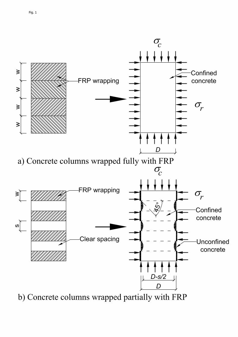
Fig. 1
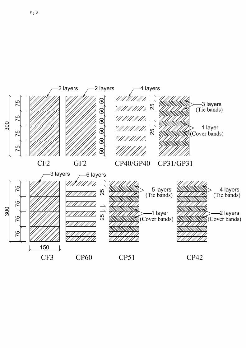
Fig. 2
LVDT
Compressometer
Fig. 3

4a.
4d.
. GF2
CP60
4
4b. CP40 (σ
4e. GP
σc = fco’) 4
P40
4c. CP40 (σ
4f. GP
σc ~ fcu’)
P31
Fig. 4

0
10
20
30
40
50
60
70
80
0.0 0.5 1.0 1.5 2.0 2.5 3.0
f c(M
Pa)
εc (%)
GP40_1GP40_2GP40_3
b
0
10
20
30
40
50
60
70
80
0.0 0.5 1.0 1.5 2.0 2.5 3.0
f c(M
Pa)
εc (%)
ReferenceGF2_3GP40_2GP31_1
C d
0
10
20
30
40
50
60
70
80
0.0 0.5 1.0 1.5 2.0 2.5 3.0
f c(M
Pa)
εc (%)
GF2_1GF2_2GF2_3
0
10
20
30
40
50
60
70
80
0.0 0.5 1.0 1.5 2.0 2.5 3.0
f c(M
Pa)
εc (%)
GP31_1GP31_2GP31_3
c
a
Fig. 5

0
20
40
60
80
100
120
0.0 1.0 2.0 3.0
f c(M
Pa)
εc (%)
CP40_1CP40_2CP40_3
b
0
20
40
60
80
100
120
0.0 0.5 1.0 1.5 2.0 2.5 3.0
f c(M
Pa)
εc (%)
CF2_1CF2_2CF2_3
a
0
20
40
60
80
100
120
0.0 1.0 2.0 3.0
f c(M
Pa)
εc (%)
CP31_1CP31_2CP31_3
c
Fig. 6

0
20
40
60
80
100
120
140
0.0 1.0 2.0 3.0 4.0
f c(M
Pa)
εc (%)
CP51_1CP51_2CP51_3
c
0
20
40
60
80
100
120
140
0.0 1.0 2.0 3.0 4.0
f c(M
Pa)
εc (%)
CP60_1CP60_2CP60_3
b
0
20
40
60
80
100
120
140
0.0 1.0 2.0 3.0 4.0
f c(M
Pa)
εc (%)
ReferenceCP60_2CP51_2CP42_2CF3_1
e0
20
40
60
80
100
120
140
0.0 1.0 2.0 3.0 4.0
f c(M
Pa)
εc (%)
CF3_1CF3_2CF3_3
a
0
20
40
60
80
100
120
140
0.0 1.0 2.0 3.0 4.0
f c(M
Pa)
εc (%)
CP42_1CP42_2CP42_3
d
Fig. 7

0
20
40
60
80
100
120
140
0 0.5 1 1.5 2
f c(M
Pa)
εl (%)
Tie bandCover band
Fig. 8