optimize your gas chromatography analysis … your gas chromatography analysis through ... on-column...
TRANSCRIPT

WHITEPAPER
Optimize Your Gas Chromatography Analysis Through the Use of a Retention Gap and Integrated Guard Column
AuthorsMichel Pampaloni
PerkinElmer, Inc. France
Kyle Oberndorfer
PerkinElmer, Inc. Shelton, CT
Guy Gaspar
PerkinElmer, Inc. Consultant France
Introduction
Optimizing your gas chromatography (GC) is crucial in improving laboratory efficiencies and analytical performance. One way to optimize your GC analysis is by using retention gaps and guard columns. Although similar, they can serve different purposes. A guard column/retention gap is a short (1-5 m) piece of uncoated deactivated fused silica tubing which is placed in-line between the GC injection port and the capillary column. Guard columns are used to protect the analytical column and extend its lifetime. Retention gaps also act as guard columns, but their primary goal is to improve peak shape by focusing the sample components whenever introducing a large liquid sample onto the column.
This article illustrates the benefits of using retention gaps, the various possibilities of connecting a retention gap to the analytical column, and the use of integrated guard columns.
The Problem of Analyzing Low Concentration Analytes and How a Retention Gap Solves It
Analyzing samples with analytes at low concentrations in capillary GC is not an easy task. Of all the GC injection techniques the SPLIT injection is very common and quite easy, but is not always the best option. Often, we have to use more sophisticated techniques like Splitless and On-Column injection, which can be complicated and problematic. The common characteristic of these techniques is the presence of the sample in liquid phase.
Before going into the details, let's have a look at an example, see Figure 1.
The figure labeled “b) 0.5 µL without retention gap” in Figure 1 shows the separation of these hydrocarbons after injecting 0.5 µl of sample. The separation appears correct. However, if the concentration of solutes was 8 times lower, we would need to inject 8 times more sample. Performing a 4 µL injection to achieve that goal results in a very different chromatogram, as shown in the chromatogram labeled “a) 4 µl without retention gap”. Note how the peaks are poorly shaped and very broad. Finally, the chromatogram labeled “c) 4 µL with retention gap“ looks much better and compared favorably to the 0.5 µl result. The only difference between these two analyses is the addition of a deactivated capillary tube 1.5 m long and 0.32 mm inner diameter placed between the injector and the analytical column. This is known as a “Retention Gap”.
Figure 1. Alkane separation C12, C13 and C14 on a 8 m x 0,32 mm x 0,1 µm dimethyl-siloxane column, solvent acetone, on-Column injection. (from K. GROB book: On-Column Injection in Capillary Gas Chromatography) Please note that on many of Dr. Grob’s chromatograms the time goes from the right to the left!
Figure 2. The spreading and the fragmentation of the liquid sample into the capillary column.
We should mention that this performance anomaly exists only with certain solvents. The more commonly encountered "bad guys" (but not the only ones) are -
• Acetone
• Dichloromethane
• Benzene
• Methanol
2
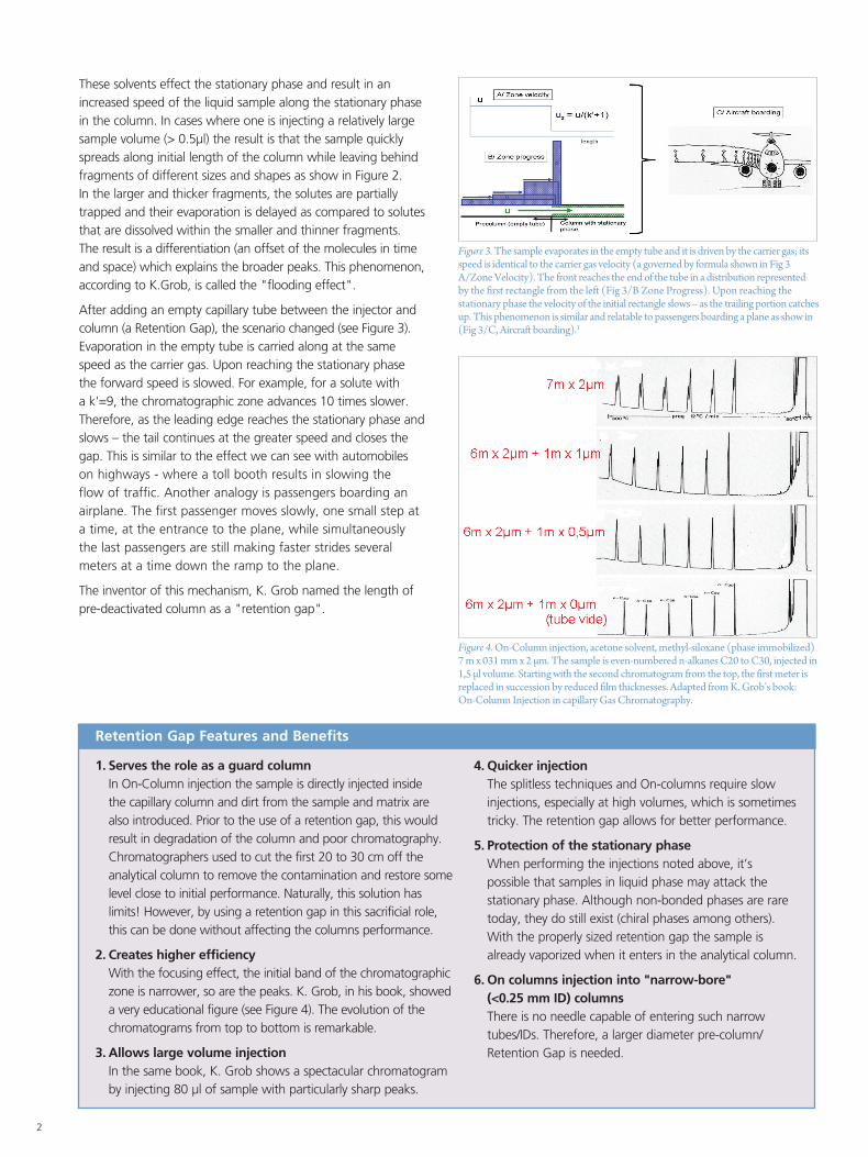
These solvents effect the stationary phase and result in an increased speed of the liquid sample along the stationary phase in the column. In cases where one is injecting a relatively large sample volume (> 0.5µl) the result is that the sample quickly spreads along initial length of the column while leaving behind fragments of different sizes and shapes as show in Figure 2. In the larger and thicker fragments, the solutes are partially trapped and their evaporation is delayed as compared to solutes that are dissolved within the smaller and thinner fragments. The result is a differentiation (an offset of the molecules in time and space) which explains the broader peaks. This phenomenon, according to K.Grob, is called the "flooding effect".
After adding an empty capillary tube between the injector and column (a Retention Gap), the scenario changed (see Figure 3). Evaporation in the empty tube is carried along at the same speed as the carrier gas. Upon reaching the stationary phase the forward speed is slowed. For example, for a solute with a k'=9, the chromatographic zone advances 10 times slower. Therefore, as the leading edge reaches the stationary phase and slows – the tail continues at the greater speed and closes the gap. This is similar to the effect we can see with automobiles on highways - where a toll booth results in slowing the flow of traffic. Another analogy is passengers boarding an airplane. The first passenger moves slowly, one small step at a time, at the entrance to the plane, while simultaneously the last passengers are still making faster strides several meters at a time down the ramp to the plane.
The inventor of this mechanism, K. Grob named the length of pre-deactivated column as a "retention gap".
Figure 3. The sample evaporates in the empty tube and it is driven by the carrier gas; its speed is identical to the carrier gas velocity (a governed by formula shown in Fig 3 A/Zone Velocity). The front reaches the end of the tube in a distribution represented by the first rectangle from the left (Fig 3/B Zone Progress). Upon reaching the stationary phase the velocity of the initial rectangle slows – as the trailing portion catches up. This phenomenon is similar and relatable to passengers boarding a plane as show in (Fig 3/C, Aircraft boarding).1
1. Serves the role as a guard column In On-Column injection the sample is directly injected inside the capillary column and dirt from the sample and matrix are also introduced. Prior to the use of a retention gap, this would result in degradation of the column and poor chromatography. Chromatographers used to cut the first 20 to 30 cm off the analytical column to remove the contamination and restore some level close to initial performance. Naturally, this solution has limits! However, by using a retention gap in this sacrificial role, this can be done without affecting the columns performance.
2. Creates higher efficiency With the focusing effect, the initial band of the chromatographic
zone is narrower, so are the peaks. K. Grob, in his book, showed a very educational figure (see Figure 4). The evolution of the chromatograms from top to bottom is remarkable.
3. Allows large volume injection In the same book, K. Grob shows a spectacular chromatogram
by injecting 80 µl of sample with particularly sharp peaks.
4. Quicker injection The splitless techniques and On-columns require slow
injections, especially at high volumes, which is sometimes tricky. The retention gap allows for better performance.
5. Protection of the stationary phase When performing the injections noted above, it’s
possible that samples in liquid phase may attack the stationary phase. Although non-bonded phases are rare today, they do still exist (chiral phases among others). With the properly sized retention gap the sample is already vaporized when it enters in the analytical column.
6. On columns injection into "narrow-bore" (<0.25 mm ID) columns There is no needle capable of entering such narrow tubes/IDs. Therefore, a larger diameter pre-column/Retention Gap is needed.
Figure 4. On-Column injection, acetone solvent, methyl-siloxane (phase immobilized) 7 m x 031 mm x 2 µm. The sample is even-numbered n-alkanes C20 to C30, injected in 1,5 µl volume. Starting with the second chromatogram from the top, the first meter is replaced in succession by reduced film thicknesses. Adapted from K. Grob’s book: On-Column Injection in capillary Gas Chromatography.
Retention Gap Features and Benefits

3
Product Qty. Size BrassPart No.
Stainless SteelPart No.
Bulkhead Adapter 1 1/4 in. to 1/4 in. tube N9301267
Back Ferrule pkg. 5 1/16 in.
1/8 in.
1/4 in.
N9300040
N9300036
N9300030
N9300042
N9300038
N9300032
Cross Union pkg. 1 1/8 in. N9301259
Front Ferrule pkg. 5 1/16 in.
1/8 in.
1/4 in.
N9300041
N9300037
N9300031
N9300043
N9300039
N9300033
Male AdapterTube to Pipe
pkg. 1 1/4 in. tube to 1/8 in. NPT N9301266
Male Connector pkg. 1 1/8 in. to 1/8 in. NPT
1/8 in. to 1/4 in. NPT
1/4 in. to 1/8 in. NPT
1/4 in. to 1/4 in. NPT
N9301253
N9301254
N9301255
N9301269
Nut pkg. 5 1/16 in.
1/8 in.
1/4 in.
N9300058
N9300056
N9300054
N9300059
N9300057
N9300055
Plug pkg. 1 1/16 in.
1/8 in.
1/4 in.
N9300060
N9301268
N9300053
N9300061
N9301233
Union pkg. 2 1/16 in.
1/8 in.
1/4 in.
N9300048
N9300046
N9300044
N9300049
N9300047
Union Tee pkg. 1 1/16 in.
1/8 in.
1/4 in.
N9301221
N9301222
N9301223
Reducing Union pkg. 1 1/8 in. to 1/16 in.
1/4 in. to 1/8 in.
1/4 in. to 1/16 in.
N9300051
N9300050
N9301227
N9301225
N9301226
Table 1. Swagelok™ fittings.
Connecting a Retention Gap to the Analytical Column and Implementation
There are different ways to connect a retention gap to the analytical column. But how do you choose the right length and deactivation type?
There are two more popular options:1. Connection with Swagelok™ type connectors (see Table 1) with double ferrule inside. The assembly is not always straightforward
and does require some experience.
2. Using universal connectors (see Tables 1 and 2.)

4
Dimension Part No.
Universal Connector (pkg. 5) N9302149
Metal Universal Connectors: 0.25 mm i.d. (pkg. 10) N9301167
Universal Y Splitter (pkg. 1) N9303448
Polyimide Sealing Resin (5 g) N9301343
Undeactivated Presstight Column Connectors (pkg. 5) N9303962
Universal ConnectorsTable 2. Universal connectors.
For column “tightness” it is very important to make clean cuts at the ends of the fused silica capillary tubes before inserting them into the connector. Some users suggest wetting the ends in methyl-pyrolidone to soften the polyimide layer. Others advise putting the resin paste inside the connector to achieve the same goal.
Whatever the choice of connector (Swagelok or Universal), it will still likely remain the Achilles heel of the system – especially for GC/MS. Air intrusion in these situations is almost inevitable.
Retention Gap with Integrated Connection. As mentioned just above, the connection is often the weakest point of the system. Currently the preferred solution for this problem is using columns with integrated guards – thus requiring no interconnection.
Capillary columns with an integrated guard offer multiple advantages over systems with a pre-column and a connector:
• No leaks for a more robust method
• No column connections for easier, faster maintenance
• No peak distortions due to connector dead volume and thermal capacity
Some chromatography literature on this subject provides complicated tables. However, based on our experience, very few simple rules will cover the vast majority of situations:
A. Required length
ID =0,32 mm : L= 0,25 m/µl injected + 1 m
ID =0,25 mm : L= 0,40 m/µl injected + 1 m
After selecting the appropriate ID, you can apply these equations, where the first term is capacity (proportional to the injected volume) to ensure the best performance. The addition of one extra meter serves both the role of guard column and allows for gradual cutting/trimming to remove contamination from the column.
B. Retention gap deactivation
In order to improve the focusing effect of the retention gap, it is recommended to use deactivated inner surface pre-columns. The type of deactivation is chosen as a function of the sample solvent being used:
• Non-polar deactivation for injection of none or weakly polar solvents for instance alkanes, carbon disulfide, and ethers.
• Intermediate polar deactivation for injection moderately polar solvents: methylene chloride (dichloromethane), and toluene.
• Polar deactivation for injection of strongly polar solvents such as acetonitrile, methanol, and water.
This is an important selection criterial because an incompatible solvent can result in the formation of droplets inside the tube.
Conclusion
In summary, depending on the sample matrix and injection technique that you use, you can dramatically improve your chromatographic results by simply using a retention gap. Among the various potential solutions, the use of integrated guard columns, where connections aren't required, is by far the best choice.
We offer a wide choice of Integrated Guard columns, for your GC regardless of instrument make, model or manufacturer, which eliminate the inconvenience and problems that often result in trying to make leak-free connections between a guard column and the analytical column. These innovative columns incorporate both guard and analytical columsn in a continuous length of tubing, thus eliminating the issue.
The Integrated Guard column is so cost-effective that we challenge you to compare our price against that of a conventional connection, even if you assemble it yourself. See the vast variety of PerkinElmer Integrated Guard columns in Table 3.
Figure 5. PerkinElmer undeactivated presstight column connector Product Number N9303962.2

For a complete listing of our global offices, visit www.perkinelmer.com/ContactUs
Copyright ©2016, PerkinElmer, Inc. All rights reserved. PerkinElmer® is a registered trademark of PerkinElmer, Inc. All other trademarks are the property of their respective owners. 012689_01 PKI
PerkinElmer, Inc. 940 Winter Street Waltham, MA 02451 USA P: (800) 762-4000 or (+1) 203-925-4602www.perkinelmer.com
Elite-1
30 m
ID df (mm) Temp Limits (°C) Integrated Guard Part No.
0.25 mm 0.25 -60 to 330/350 5 m N9305600
0.53 mm 1.00 -60 to 330/350 5 m N9305601
5.00 -60 to 340/360 5 m N9305602
Elite-5
30 m 60 m
ID df (mm) Temp Limits (°C)Integrated Guard Part No. Part No.
0.25 mm 0.25 -60 to 330/350 5 m N9305603
0.25 -60 to 330/350 10 m N9305604
1.00 -60 to 330/350 5 m N9305605
0.32 mm 0.25 -60 to 330/350 5 m N9305606 N9305607
1.00 -60 to 330/350 5 m N9305608
0.53 mm 5.00 -60 to 340/360 5 m N9305609
Elite-5 ms II
15 m 30 m
ID df (mm) Temp Limits (°C)Integrated Guard Part No. Part No.
0.25 mm 0.10 -60 to 330/350 5 m N9305610
0.25 -60 to 330/350 5 m N9305611 N9305612
0.25 -60 to 330/350 10 m N9305613
0.50 -60 to 330/350 5 m N9305614
0.50 -60 to 330/350 10 m N9305615 N9305616
0.32 mm 0.25 -60 to 330/350 5 m N9305617
1.00 -60 to 330/350 5 m N9305618
Elite-5 ms
30 m 60 m
ID df (mm) Temp Limits (°C)Integrated Guard Part No. Part No.
0.25 mm 0.10 -60 to 330/350 5 m
0.25 -60 to 330/350 5 m N9305619
0.25 -60 to 330/350 10 m N9305620 N9305621
0.50 -60 to 330/350 5 m N9305622 N9305623
0.50 -60 to 330/350 10 m N9305624
0.32 mm 0.50 -60 to 330/350 5 m N9305625
1.00 -60 to 330/350 5 m N9305626
Elite-624
30 m
ID df (mm) Temp Limits (°C) Integrated Guard Part No.
0.25 mm 1.40 -60 to 330/350 5 m N9305627
0.32 mm 1.80 -60 to 330/350 5 m N9305628
0.53 mm 3.00 -60 to 340/360 5 m N9305629
Elite-1301
30 m
ID df (mm) Temp Limits (°C) Integrated Guard Part No.
0.53 mm 3.00 -60 to 330/350 5 m N9305630
Elite-1701
30 m
ID df (mm) Temp Limits (°C) Integrated Guard Part No.
0.25 mm 0.25 -60 to 330/350 5 m N9305631
Elite-WAX ETR
30 m
ID df (mm) Temp Limits (°C) Integrated Guard Part No.
0.25 mm 0.25 -60 to 330/350 5 m N9305632
0.32 mm 1.00 -60 to 330/350 5 m N9305633
0.53 mm 1.00 -60 to 340/360 5 m N9305634
Table 3. Integrated Guard Columns.
Integrated Guard Columns
References
1,2. Hüthig Buch Verlag GmbH Heidelberg GROB, Konrad: On-column injection in capillary gas chromatography; basic technique, retention gaps, solvent effects / by Konrad Grog – 2.ed. – Heidelberg : Huethig, 1991 1. Page 121, Figure A42. 2. Page 374, Figure C5