optimizationanalysisofsettlementparametersfor...
TRANSCRIPT
Research ArticleOptimization Analysis of Settlement Parameters forPostgrouting Piles in Loess Area of Shaanxi China
Zhijun Zhou 1 Shanshan Zhu1 Xiang Kong12 Jiangtao Lei 1 and Tong Liu 3
1School of Highway Changrsquoan University Xirsquoan Shaanxi 710064 China2China State Construction Silk Road Investment Group CoLtd Xirsquoan Shaanxi 710065 China3School of Science Xirsquoan University of Architecture and Technology Xirsquoan Shaanxi 710055 China
Correspondence should be addressed to Tong Liu liutongxauateducn
Received 6 January 2019 Revised 2 March 2019 Accepted 27 March 2019 Published 18 April 2019
Academic Editor Giulio Dondi
Copyright copy 2019 Zhijun Zhou et al is is an open access article distributed under the Creative Commons AttributionLicense which permits unrestricted use distribution and reproduction in any medium provided the original work isproperly cited
e settlement calculation of postgrouting piles is complex and depends on the calculation method and parameters Static loadtests were conducted to compare the settlement characteristics of nongrouting and postgrouting piles and three vital parametersin the layer-wise summation method were revised to predict the settlement of postgrouting piles e elastic compressioncoefficient was deduced based on the MindlinndashGeddes method by considering the influence of the change in the pile sideresistance distribution and end resistance ratio on the elastic compression after grouting e relationship between the com-pression modulus and soil gravity stress and cone penetration resistance were established respectively using experimental datae optimum value of the settlement empirical coefficient was determined using regional data Finally we used the postgroutingpile of the WuqindashDingbian expressway as a practical example e results obtained from the layer-wise summation method afterparametric optimization were close to the measured values e results of this study provide reference data and guidance for thesettlement calculation of postgrouting piles in this area
1 Introduction
Loess is widely distributed worldwide and accounts forabout 110 of the global land area [1] e Loess Plateau innorthwestern China is the most extensive loess accumula-tion area in the world and represents 724 of Chinarsquos loessarea In 2013 the state put forward the strategic conceptionof the ldquoNew Silk Road Economic Beltrdquo a large part of thisarea belongs to the Loess region which results in newopportunities and challenges for infrastructure constructionin the Loess area [2] e settlement of superstructures isespecially a concern for bridges that require high designaccuracy for the foundation design However the non-uniform compressibility of loess often results in significantpile settlement [3ndash5] As a means of increasing the bearingcapacity and reducing the settlement of pile foundations thepostgrouting technique has become a popular method forcast-in-place pile foundation construction [6ndash13] Howeverresearch on the settlement of postgrouting piles is relatively
limited although the settlement is a key factor in pile designerefore in this study we investigate the postgroutingtechnique for pile foundation construction to predict thesettlement of postgrouting piles in loess areas
In past decades many methods have been used to cal-culate the settlement of piles such as the theoretical load-transfer method [14ndash16] the elastic theory method [17 18]the shearing deformation method [19] numerical compu-tation methods [20ndash25] and the layer-wise summationmethod [26] Some scholars have investigated the adapt-ability of the postgrouting technique in different bearingstrata and the factors influencing the settlement and de-formation [9 27] Other scholars have considered the soilparameters and proposed an iterative solution for a singlepile after studying the interaction between the slurry andsoil a settlement calculation method was put forward basedon the shearing deformation and the theoretical load-transfer methods [28ndash30] Many scholars have used nu-merical procedures to simulate postgrouting piles to
HindawiAdvances in Civil EngineeringVolume 2019 Article ID 7085104 16 pageshttpsdoiorg10115520197085104
determine the bearing capacity and settlement characteris-tics the results showed that the simulated values were ingood agreement with the measured values [31]
Although the abovementioned methods can predict thesettlement of postgrouting piles these methods have thedisadvantage of poor applicability due to the complexity ofthe soil after grouting erefore although research on pilessettlement using the layer-wise summation method is rel-atively limited it is actually the simplest and most practicalmethod For example the settlement calculation methoddescribed in the latest edition of the Chinese Technical Codefor Building Pile Foundations [32] is based on layer-wisesummation method making it the most widely used methodin engineering design calculation However the values of thecalculation parameters are not given in this code becausethere are regional differences in the parameters for thesettlement of postgrouting piles In this study the layer-wisesummation method is used We conduct a static load testindoor test and static cone penetration test on the WuqindashDingbian expressway and determine the optimum values ofthree parameters affected by postgrouting Finally wecompare the results obtained from the layer-wise summa-tion method after parametric optimization with the mea-sured values a good agreement is obtained e results ofthis study provide data and guidance for the settlementcalculation of postgrouting piles in the loess area of northernShaanxi in China
2 Site Condition and Test Methods
21 Site Condition e WuqindashDingbian expressway (Fig-ure 1) which crosses Wuqi County and Dingbian County inChina is a key project of Shaanxi Province constructionbegan in 2015 e route starts from Zoumatai in the east ofWuqi County and ends at Shijingzi in the southeast ofDingbian County the expressway has a length of 92217 kme study area is located in the middle point of this routeeabutments on both sides of the bridge are located in the loesshill region (the loess hill region refers to the geomorphologyresulting from loess erosion copy Baidu Encyclopedia)
A geological survey and drilling indicated no surfacewater and groundwater at the drilling depth e upper soillayer is loessial loess with a thickness of 18m and all below18m are old loesse bottoms of the piles are located in thedeep old loess layer To ensure the safety and stability of thestructure the piles have to be tested
22 Test Methods e test consisted of indoor and fieldtests e indoor tests included a moisture content test(Figure 2(a)) a compression test (Figure 2(b)) a directshear test (Figure 2(c)) and an unconfined compressivestrength test (Figure 2(d)) e field tests included a staticcone penetration test (Figure 2(e)) and a static load test(Figure 4(b)) e moisture content of the soil samples wasdetermined from the moisture content test the void ratioand coefficient of compressibility were obtained from thecompression test the cohesion and internal friction anglewere obtained from the direct shear test and the unconfined
compressive strength was obtained from the unconfinedcompressive strength test the indoor test results are shownin Table 1
In the field test TS1 was the nongrouting pile and TS2was the postgrouting pile e length of the test piles andanchor piles were 25m and 30m respectively and they hadthe same diameter of 15m e test piles were 15m abovethe ground to conduct the static load test e pile body andthe aboveground part consisted of C30 and C40 concreterespectively
e installation process of the test pile was as follows (1)a rotary drilling method with high bearing capacity was usedto excavate the pile hole e location of the pile was de-termined and the drilling rig (Figure 3(a)) was moved intoposition (2) e initial drilling speed should not be too fastie no more than 2mh and the subsequent speed should beno more than 3mh e technical operating regulations[32] should be strictly observed during the drilling process(3) e first hole cleaning was carried out when the drillingreached the desired depth rotary drill bit (Figure 3(b))sweeps several laps in situ to clean sediment at pile bottom Aplumb bob was placed into the hole to measure the sedimentthickness of the two test piles after the hole cleaning thevalues were 37mm and 22mm respectively and met therequirements of being less than 50mm (4) Finished rolledthreaded reinforcing bars with a diameter of 25mm werewelded onto a steel reinforcement cage (Figure 3(c)) and thereinforcement ratio was 044 21 strain gauges(Figure 3(d)) were evenly attached to the steel reinforcementcage at 7 locations (Figure 4(a)) for each pile and the steelreinforcement cage was placed into the hole [33] (5) Due tosand and stone precipitation in the mud and the slurryfalling into the hole by rubbing against the hole wall whenthe steel reinforcement cage and the pipe (Figure 3(e)) wereinserted a second hole cleaning was conducted by using thepipe before grouting the thickness of the sediment belowthe hole was measurede sediment thicknesses of the twopiles were 33mm and 41mm respectively which was inagreement with the code [32] that specifies less than 50mmere was little difference in the sediment thicknesstherefore the bearing capacity of the pile foundation wasonly slightly affected (6) e overgrouting height was10m and finally the floating slurry on the top of the pile isremoved and the pile body is maintained (7) Installedgrouting equipment (Figure 3(f )) after concrete strength ofTS2 pile reaches 75 e slurry density of the water-cement ratio of 04 is 1700 kgm3 e equation for de-termining the grouting quantity is provided in thecode [34]
Gc apd (1)
where Gc is the quantity of grout ap is the grouting co-efficient and d is the diameter of the pile According to thecharacteristics of the bearing stratum at the pile end thereference value of the grouting coefficient ap in the referencecode [34] is 21 and the diameter of TS2 is 15m thereforethe estimated grouting quantity is 315 t and the groutingrate is less than 75 Lmin e grouting stopped when thegrouting quantity reached 315 t at this time the grouting
2 Advances in Civil Engineering
pressure reached 40MPa e distributions of soil and thespacing of stress gauges (Figure 3(d)) along the pile shaft areshown in Figure 4(a)
In the static load test an anchor pile beam counterforcedevice was used (Figure 4(b)) the load was applied in in-crements using eight identical hydraulic jacks (Figure 4(b) (i))at the top of the pile e loading-unloading method wasbased on the Chinese Technical Code for Testing of BuildingFoundation Piles (JGJ106-2014) [34] e magnitude of thefirst load step was double that of the subsequent load stepse first load step was 2000 kN and the load increment was1000 kN Each load increment was maintained after loading
until two consecutive displacements during one hour were lessthan 01mm and occurred twice continuously [33]
3 Static Load Test Results andCalculation Process
31 Settlement Calculation e settlement of the pile headwas calculated by using the average of 4 automatic dis-placement acquisition instruments (Figure 4(b) (ii)) in-stalled at the pile head after each loading step was completede settlement of two piles measured under various loads isshown in Table 2 among which s1 s2 s3 and s4 are the
(a) (b) (c) (d) (e)
Figure 2 Indoor and field tests (a) Moisture content test (b) Compression test (c) Direct shear test (d) Unconfined compressive strengthtest (e) Static cone penetration test
Table 1 Physical properties of the soil layers
Name andlayer number
Depthh (m)
Density(gcm3)
Moisturecontent ω
()
Voidratio e
Coefficient ofcompressibility a1minus2
(MPaminus1)
Cohesionc (kPa)
Internalfriction angle
φ (deg)
Unconfinedcompressive strength
(kPa)
1 Loessialsoil Q
pl4
0sim18 168 163 0883 035 68 284 164
2 Old loessQε0l
218simgt50 185 79 0586 012 305 258 145
Loess area
Silk Road Economic Belt Yanrsquoan
China
Wuqi county
Dingbian county
Test site
Wuqi-DingbianExpressway
Yanrsquoan city
Figure 1e location of the study area (map data copy 2018 Baidumaps loess area distribution copy Baidu encyclopedia the picture was taken byZhijun Zhou)
Advances in Civil Engineering 3
automatic acquisition instruments installed on pile TS1 s5s6 s7 and s8 are the automatic acquisition instruments in-stalled on pile TS2 s is the average of settlement under acertain load level e settlement of two piles under eachloading step is shown in Figure 5
32 Axial Force of Pile Body Calculation Axial force of thepile body is converted from the frequency of stress gauges onsteel cagee pile end resistance was approximately equal to
the axial force calculated by using the lowest level stressgaugee calculation process is as follows According to theconversion formula of the stress gauges the axial force of thesteel bars can be obtained
Nsi K fi2 minusf2i01113872 1113873 + B (2)
whereNsi is the axial force of the steel bars i is the number ofstress gauges 1sim7 from top to bottom K is the calibrationcoefficient fi0 is the initial frequency of stress gauges each
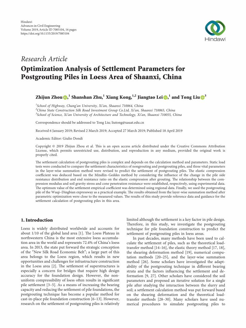
(a) (b) (c) (d) (e) (f )
Figure 3 (a) Drilling rig (b) Drill bit (c) Steel reinforcement cage (d) Reinforcement stress gauge (e) Pipe (f ) Grouting equipment
Depth (m)
Loessial soil
Old loess
TS1150
35
65
11
155
24525
30
35
Reinforcementstress gauge
45
45
45
45
3
3
20
TS2
05
(a)
Anchor bar
Main beamSecondarybeam
Reference beam
(ii) Automaticdisplacementacquisitioninstrument
(i) Hydraulic jack
(b)
Figure 4 (a) e distributions of soil and the spacing of stress gauges along the pile shaft (b) Anchor pile beam counterforce deviceconsisting of (i) hydraulic jack (ii) automatic displacement acquisition instrument anchor bar main beam secondary beam and referencebeam
Table 2 Settlement of two piles measured under various loads
Load (kN) 2000 3000 4000 5000 6000 7000 8000 9000 10000 11000 12000 13000 14000 15000s1 (mm) 016 035 036 045 007 077 111 411 1556 2112 2364s2 (mm) 022 033 038 043 006 089 124 400 1387 2172 3422s3 (mm) 023 032 034 045 009 090 120 389 1453 1980 2966s4 (mm) 023 044 044 043 013 076 109 316 1500 2043 3296s (mm) 021 036 038 044 007 083 116 379 1474 2077 3012s5 (mm) 006 049 100 030 0014 0024 109 024 108 097 111 13 084 287s6 (mm) 007 05 111 041 0007 0030 110 025 099 097 121 116 066 309s7 (mm) 05 055 097 037 0008 0031 100 019 100 107 117 125 073 278s8 (mm) 01 058 108 044 0011 0027 097 028 105 107 115 125 069 322s (mm) 007 053 104 038 001 0028 104 024 103 102 116 124 073 299
4 Advances in Civil Engineering
stress gauge has an initial frequency fi0 when it leaves thefactory and fi is the frequency produced by using the sensorin the stress gauges under axial force B is the calculatedcorrection value which is 0 in this paper So the strain ofsteel bar is as follows
εsi Nsi
EsAs (3)
where εsi is the strain of the steel bar Es is the elastic modulusof the steel bar and Es of steel bar in this test is 200GPa andAs is the section area of steel bar which is 00004909m2 inthis test Since the reinforcement ratio is only 044 as-suming that the same strain of concrete and steel bars in thesame section as the stress gauge the axial force of the pilebody in section i is as follows
Qni EcAc + EsAs( 1113857εsi (4)
where Qni is the axial force of the pile body under stage loadn and εsi is the strain of concrete Ec is the elastic modulus ofconcrete which is 30GPa in this test Ac is the section area ofconcrete εsi is the average value of εsi For example whencalculating the axial force of the pile TS2 under 3000 kN theresults are shown in Table 3 And the axial force diagrams ofTS1 and TS2 are shown in Figure 6
33 Frictional Resistance Calculation Frictional resistancealong each pile was calculated by dividing the difference oftwo consecutive axial forces by the pile shaft area betweenthe two stress gauges [27 35] and side friction strength canbe calculated by the following formula
qi Qi minusQiminus1πdhi
(5)
where qi is the side friction strength along the pile shaft d isthe diameter of the pile and hi is the height between adjacent
sections For example the frictional resistance strength ofTS2 pile under various loads is shown in Table 4 And thefrictional resistance strength diagrams of TS1 and TS2 areshown in Figure 7
4 Layer-Wise Summation Method
e total pile head displacement includes the compression ofthe foundation soil and the elastic compression of the pilebody [33] the compression of the foundation soil is cal-culated using the one-way layer summation method eformulas are as follows
s ψ 1113944
n
i1
σziEsiΔzi + se (6)
se ξeQl
EAps (7)
where Aps is the cross section of the piles Esi is the com-pression modulus of layer i of the soil and E is the elasticmodulus of the pile body e reinforcement portion is lowand the reinforcement ratio is only 044 therefore theelastic modulus of concrete can be used for the pile bodyelastic modulus in general e Code for Design of ConcreteStructures (GB50010-2010) [36] was used therefore Ec ofthe C30 concrete is 30GPa l is the length of the pile n is thenumber of soil layers Q is the pile top load s is the total pilehead displacement se is the elastic compression of the pilebody Δziis the thickness of layer i of the soil σzi is theadditional stress in layer i of the soil calculated by theMindlinndashGeddes method and ξe is the elastic compressioncoefficient of the pile bodye end-bearing pile ξe is 10efriction pile ξe is 0667 when ldle 30 ξe is 05 when ldge 50 alinear interpolation between the two is used ψ is the set-tlement empirical coefficient which is 1 when there are noregional data
Mindlin [37] proposed an analytical solution of theadditional stress generated by the force at a point in theinterior of a semiinfinite solid Based on Mindlinrsquos studyGeddes [38] deduced the formula for calculating the ad-ditional stress of a single pile for three kinds of pile sideresistance distributions Geddesrsquo method divides the piletop load (Figure 8(a)) into three parts one is the axial force(Figure 8(b)) transmitted along the pile body to the pileend the other is the rectangular part (Figure 8(c)) of thepile side friction diagram after the pile side friction dis-tribution diagram is split into rectangular and triangularparts and the third is the triangular part (Figure 8(d)) ofthe pile side friction diagrame outstanding advantage ofGeddesrsquo method is that it unifies the problem of pile-soilinteraction with the concept of additional stress in thelayer-wise summation method which is widely used inChina e load-sharing diagram of piles is shown inFigure 8
Considering the influence of the pile diameter on theMindlin solution the additional stress at a calculation pointis calculated as follows [34]
0 2000 4000 6000 8000 10000 12000 14000 16000 180000
10
20
30
40
50
60
70
80
Settl
emen
t (m
m)
Load (kN)
TS1TS2
Figure 5 Settlement of TS1 pile and TS2 pile under each loadingstep
Advances in Civil Engineering 5
σzi σzpi + σzsri + σzsti (8)
σzpi αQ
l2Ipi (9)
σzsri βQ
l2Isri (10)
σzsti (1minus αminus β)Q
l2Isti (11)
where Ipi Isri and Isti are the vertical stress coefficients of anypoint in the soil under pile end load load shared byrectangular-shaped friction resistance and load shared bytriangular-shaped friction resistance respectively this was
2000
4000
6000
8000
1000
0
1200
0
24
20
16
12
8
4
0
Load (kN)
Dep
th (m
)
2000kN3000kN4000kN5000kN
6000kN7000kN8000kN9000kN
10000kN11000kN12000kN
(a)
1000
2000
3000
4000
5000
6000
7000
8000
9000
1000
0
1100
0
1200
0
1300
025
20
15
10
5
0
Load (kN)
Dep
th (m
)
Pile head load Q0
Pile end load Qb
2000kN3000kN4000kN5000kN
6000kN7000kN8000kN9000kN
10000kN11000kN12000kN
(b)
Figure 6 e axial force of piles (a) TS1 and (b) TS2
Table 3 Axial force calculation table of the pile TS2 body under 3000 kN
Depth (m) Number i K fi0 fi Nsi εsi εsi Q2i
05 1(a) 00002670 13567 13409 minus1138009536 minus000011591105 1(b) 00002705 1472 14629 minus7224403095 minus735832Eminus 0505 1(c) 00002671 14912 14728 minus1456699296 minus000014837 minus0000112621 minus399635 2(a) 00002675 14445 14331 minus87752412 minus893791Eminus 0535 2(b) 00002680 14202 1407 minus1000150272 minus000010186935 2(c) 00002677 14528 14424 minus8060468416 minus820989Eminus 05 minus911157Eminus 05 minus32337 3(a) 00002679 14609 14492 minus9121504743 minus929059Eminus 057 3(b) 00002681 14435 14311 minus9556435224 minus973359Eminus 057 3(c) 00002667 1475 14661 minus6981083193 minus711049Eminus 05 minus871156Eminus 05 minus3091115 4(a) 00002671 13849 13737 minus8252407072 minus840539Eminus 05115 4(b) 00002779 14651 14544 minus8681220835 minus884215Eminus 05115 4(c) 00002665 14018 13893 minus9297851875 minus947021Eminus 05 minus890591Eminus 05 minus316016 5(a) 00002668 1474 14589 minus1181571557 minus000012034716 5(b) 00002669 14305 1412 minus1403527013 minus000014295416 5(c) 00002682 13935 13845 minus67055364 minus682984Eminus 05 minus0000110533 minus3922205 6(a) 00002688 14253 14179 minus5655465984 minus57603Eminus 05205 6(b) 00002665 14395 14232 minus1243542566 minus0000126659205 6(c) 00002680 14793 14743 minus3957824 minus403119Eminus 05 minus748581Eminus 05 minus2656245 7(a) 00002669 14711 14653 minus4545605928 minus462987Eminus 05245 7(b) 00002672 14304 14249 minus419614888 minus427393Eminus 05245 7(c) 00002675 14677 14649 minus21965174 minus223724Eminus 05 minus371368Eminus 05 minus1317
6 Advances in Civil Engineering
Tabl
e4
efrictio
nalresistance
streng
thof
theTS
2pile
Load
(kN)
2000
q i(kPa
)3000
q i(kPa
)4000
q i(kPa
)5000
q i(kPa
)6000
q i(kPa
)7000
q i(kPa
)8000
q i(kPa
)9000
q i(kPa
)10000
q i(kPa
)11000
q i(kPa
)12000
q i(kPa
)0m
2000
3000
4000
5000
6000
7000
8000
9000
10000
11000
12000
05m
1990
42985
63977
104972
125968
146959
177952
208947
239935
2810928
3111916
3635m
1912
62868
83810
124761
155720
186667
217612
248564
279504
3110408
3711297
4465m
1805
82705
113603
154503
185402
236301
267205
298120
318950
399723
4810506
56115m
1603
102405
143271
164059
214824
275656
206504
337351
368009
448608
539170
6316
m1421
92124
132949
153614
214208
294928
345713
376469
426939
507308
517689
70205m
1225
91871
122627
153157
223534
324153
374793
435391
515697
595851
696088
76245m
1047
81579
142193
202588
272730
383124
493638
554047
634148
734168
794249
87
Advances in Civil Engineering 7
determined based on the data in Appendix F of the code[32] σzpi is the additional stress caused by the pile endresistance at the calculation point σzsri and σzsti are theadditional stress at the calculation point when the pile sideresistance is rectangular- or triangular-shaped respectivelyand α is the pile end resistance ratio which is the average ofthe ratio of the axial force at the pile end to the top load of thepile under different loads in the axial force diagram of thepile β is the side resistance ratio which is the ratio of thearea of the rectangular part to the top load of the pile in thediagram of the side resistance distribution
In equations (6)ndash(11) Aps E l and Δziare assumed at thedesign stage α and β are obtained from the pile testing data
and σzi is calculated using equations (8)ndash(11) e crucialparameters ξe Esi and ψ in the layer-wise summation methoddepend on the complexity of the soil and are commonlyestablished using regional data therefore these three pa-rameters will be optimized using the WuqindashDingbian ex-pressway test data
5 Parameters Calculation and Optimization
In this test the pile head settlement of the nongrouting pileTS1 was calculated using the layer-wise summation methodHowever when this method is used to calculate the set-tlement of the postgrouting pile TS2 the values of ξe Esi andψ need to be optimized separately as follows
Q
dz
L = + +
αQ βQ (1 minus α minus β)Q
0
(a) (b) (c) (d)
Figure 8 Load-sharing diagram of piles
0 20 40 60 80 100 120
25
20
15
10
5
0
Dep
th (m
)Side friction resistance (kPa)
2000kN3000kN4000kN5000kN
6000kN7000kN8000kN9000kN
10000kN11000kN12000kN
(a)
0 20 40 60 80 1000
5
10
15
20
25
Dep
th (m
)
Side resistance (kPa)
2000kN3000kN4000kN5000kN
6000kN7000kN8000kN9000kN
10000kN11000kN12000kN
nm
qs (y)
m
Trapezoid
(b)
Figure 7 e frictional resistance strength diagram of (a) TS1 and (b) TS2 along the pile shaft
8 Advances in Civil Engineering
51 Modified Elastic Compression Coefficient e pile bodycompression accounts for a large proportion of the totalsettlement of pile so the pile body compression is veryimportant in calculating the settlement of pile [33] Duringthe calculation different end resistance ratios and side re-sistance distributions will affect the elastic compression ofthe pile body [39] Especially after grouting the elasticcompression coefficient changes due to changes in the sideresistance distribution and the end resistance ratio How-ever the specific values given in the code [32] do not takeinto account the effect of postgrouting erefore the elasticcompression se(y) of the postgrouting pile needs to berecalculated and this paper proposes a method to clarify theelastic compression coefficient using the MindlinndashGeddesmethod And the calculation model of pile compression isshown in Figure 9
Assuming that Q0 is the pile head load and qs(y) is theside resistance at a given depth y the axial forceQy at depth ycan be defined using the following equation
Qy Q0 minus πd 1113946y
0qs(y)dy (12)
Assuming that the elastic compression of the pile islinearly elastic the unit elastic compression dse of the dysegment at depth y can be described as
dse Qy
ApsEdy (13)
By integrating (13) the elastic compression of the pilebody above depth y is obtained
se(y) 1113946y
0
Qy
ApsEdy
1ApsE
1113946y
0Qydy (14)
erefore the elastic compression se of the whole pile isdefined as
se 1
ApsE1113946
l
0Q0 minus πd 1113946
l
0qs(y)dy1113890 1113891dy (15)
Axial force and side resistance of pile TS2 under differentloads obtained from field test are shown in Figures 6(b) and7(b) α is the average ratio of pile end load to pile head loadunder the same load β is the ratio of the area of the rect-angular part to the pile head load in the diagram of sideresistance distribution e shape of the side resistancedistribution is similar to a trapezoid thus based on theMindlinndashGeddes method this paper only considered thecase when qs(y) is a trapezoid e formula Qb αQ0 can beobtained by assuming α is the end resistance ratio and Qb isthe pile end load And assuming that the pile head sideresistance is m the ratio of pile head side resistance to pilebottom side resistance is 1 n so the pile end side resistanceis nm as shown in Figure 7(b) e side resistance of thewhole pile can be written as
1113946l
0qs(y)dy
(1minus α)Q0
πd
m(1 + n) times l
2 (16)
e value of m is derived from (16)
m 2(1minus α)Q0
(1 + n)πdl (17)
Figure 7(b) shows that the linear expression of qs(y) is
qs(y) m(nminus 1)y
l+ m (18)
By substituting equation (17) into (18) qs(y) in the shapeof a trapezoid becomes
qs(y) 2(nminus 1)(1minus α)Q0
πdl(1 + n)middoty
l+2(1minus α)Q0
πdl(1 + n) (19)
By substituting (19) into (15) se can be written as
se Q0l
ApsEminus
(n + 2)(1minus α)Q0l
3(1 + n)ApsE
n + 23 + 3n
α +2n + 13 + 3n
1113874 1113875Q0l
ApsE
(20)
In order to remain consistent with ξe in the code [32] amodified compression coefficient ξeprime is proposed in thisstudy therefore se can be written as
se ξprimeQ0l
ApsE f(α)
Q0l
ApsE (21)
erefore the relationship between ξeprime and α can bedefined by the following equation
ξeprime n + 23 + 3n
α +2n + 13 + 3n
(22)
52 Changes in the End Resistance Ratio and Pile Diameter
521 Change in the End Resistance Ratio e cement slurryexerts functions on the loess soil at the bottom of the pile atthe same time during grouting including penetrationcompaction and cleavage especially compaction andcleavage e loose soil or cracks are cemented to a cementmixture with certain strength by penetration compactionand cleavage as the cement slurry is applied under pressurewhich effectively improves the end resistance and increasesthe end resistance ratio [40] In order to determine thechange in α after grouting the end resistance of the piles TS1and TS2 under different loads is determined as shown in
Qy
Q0
y l
Qb
dsedy
qs (y)
Figure 9 Calculation model of pile compression
Advances in Civil Engineering 9
Figure 10(a) It can be seen that the load transferred from thetop of the pile to the pile end is significantly larger for TS2(postgrouting) than for TS1 (nongrouting) under the sameload that is α is increased
e ratio of the increase in the end resistance ratio ofpile TS2 to that of pile TS1 under different loads isexpressed as the improvement coefficient of the end re-sistance ratio ε which is expressed in percentage Wecompared our results with those of postgrouting testscarried out in two other projects in this region with thesame soil layers and the same piles and measured using thesame test method by the engineering staff e statisticalresults are shown in Figure 10(b) It can be seen that α ishigher after grouting in most cases that is the loadtransferred to the pile end is higher and the coefficient ε isin the range of 40sim120 therefore the average value of80 is used for the calculation
e ratio of the TS1 pile end resistance to the pile topload is about 02 (Figure 10(a)) that is α is 02 therefore TS1is the friction pile and ldlt 30 the corresponding ξe de-termined based on the code [32] is 0667 It can be seen fromFigure 7(b) that 1 n is about 1 2 and α after grouting iscalculated as 036 by multiplying 02 and 18 therefore ξeprime is0716 according to equation (22) e elastic compressioncoefficient is higher after the revision indicating a highercompression of the pile body
522 Change in the Pile Diameter Due to the high groutingpressure at the pile end and the low permeability of thefoundation soil part of the serous fluid moves upward in thegap between the pile body and the soil surrounding the pileforming a layer of cement slurry around the pile [40] In thisstudy the Mindlin solution which considers the influence ofthe pile diameter is used to calculate the additional stresstherefore the stress coefficient changes with the change inthe pile diameter which affects the calculation results [41]erefore the change in the pile diameter has to be revised
Taking pile TS2 as an example mud spillover(Figure 11(a)) occurred at the top of the pile during the laststage of grouting e soil was excavated along the pile bodyafter grouting and a vertical cement shell (Figure 11(b)) wasfound around the pile erefore it was assumed that thecement slurry between the soil and the pile interface seepedto the top of the pile along the pilesoil interface e verticaldistance between the cement shell and the pile body wasmeasured at two locations at four different depths along thepile e statistical results are shown in Table 5 For sim-plified calculation an average value of 1575mmwas taken asthe diameter of the pile after grouting erefore the di-ameter of the pile TS2 after grouting was 105 times largerthan that of the pile before grouting as shown inFigure 11(c)
523 Compression Modulus e compression modulus is avital parameter when using the layer-wise summationmethod to calculate the settlement of the foundation soil Inmost cases the settlement of the foundation soil is onlycalculated by using the compression modulus Es1-2
measured in the pressure range of 100 kPasim200 kPa How-ever the level of gravity stress and additional stress farexceeds 200 kPa in practical applications therefore theinfluence of gravity stress on the compression modulusshould be considered when calculating the settlement [42]
Drilling was conducted in five engineering areas on theWuqindashDingbian expressway and the soil was sampledduring the test Five core samples were obtained and theirunit weights ci (i is the serial numbers of the soil samplesi 1sim5) were measured indoors e depth zj (j is the serialnumber of the calculation point from top to bottom j 1sim5)of the calculation point of the soil sample at P1 200 kPaP2 300 kPa P3 400 kPa P4 500 kPa and P5 600 kPa iscalculated respectively by ci using the formula zj Pjc ecalculation results are shown in Figure 12
e compression test was applied to the five core samplesto obtain Esz and Es1-2 of the soil samples at 25 positionse reliability of the linear model that was used to describethe relationship between the ratio of Esz and Es1-2 and P isassessed as shown in Figure 13(a) is linear relationshipcan be described using the following equations
Esz
Es1minus2 000463P + 01721 (23)
Esz (000463P + 01721)Es1minus2 (24)
Esz (000463ch + 01721)Es1minus2 (25)
where h is the soil depth P is the soil gravity stress and c isthe unit weight of the soil
Equation (25) is highly reliable (R2gt 091) Assumingthat c 185 kNm3 as can be seen from equation (25) Esz isabout equal to Es1-2 when h 10m erefore Esz within10m can take Es1-2 but when the depth is more than 10mEsz continues to increase with the increase in P As shown inFigure 13(a) Esz is already two times larger than Es1-2 whenP 380 kPa therefore the values of Es1-2 are no longersuitable erefore Esz within the range of compression canbe calculated by using equation (25)
In addition the double bridge cone penetration test wasperformed near the drilling points in the five engineeringareas Another method for calculating Esz is obtained byanalyzing the relationship between the cone resistance qcmeasured at the same depth as the 25 positions and Esz asshown in Figure 13(b)
e resulting expression for qc and Esz is given by thefollowing equation
Esz 2631qc + 7177 (26)
Equation (26) is highly reliable (R2gt 087) thereforethere is a significant correlation between qc and Esz In orderto verify the rationality of equation (26) the values of Eszobtained from the abovementioned two methods werecompared to ensure that they were consistent with the resultin Figure 14 erefore Esz at any depth can be calculatedusing the two methods (equations (25) and (26)) whencalculating the settlement in the loess area of northernShaanxi China
10 Advances in Civil Engineering
e tted equations (25) and (26) can be used on the onehand to revise Esz obtained from the compression test so thatan accurate value of Esz of the loess in this area can beobtained on the other hand the workload associated witheld investigations and indoor compression tests are re-duced resulting in time and cost savings
Zhou et al [43] found that the soil around the groutingpoint was continuously compressed and the porositygradually decreased during the grouting process resulting inthe change in Esz e compression of the soil was mostapparent in the range of 05m around the grouting pointerefore the compression modulus improvement
coecient ϕ is introduced to revise Esz at the end of thepostgrouting pile
In order to study the compression modulus improve-ment coecient ϕ of soil around the grouting point formulaP ch can be used to calculate the soil gravity stress P in therange of 1m at pile tip in which c is 185 gcm3 and h are245m 2475m 25m 2525m 255m 2575m 26m2625m and 265m respectively erefore the soil gravitystress P at dierent depths near the grouting point are4333MPa 4579MPa 4625MPa 4671MPa 4718MPa4764MPa 481MPa 4856MPa and 4903MPa en Eszcan be calculated according to formula (24) We compared
2000 4000 6000 8000 10000 12000500
1000
1500
2000
2500
3000
3500Pi
le en
d re
sista
nce (
kN)
Pile head load (kN)
TS2 (postgrouting pile)TS1 (nongrouting pile)
α = 0325α = 025
α = 021α = 02
α = 0175α = 0186
α = 02α = 0189
α = 02α = 0201
α = 0193
α = 02
(a)
00 05ε
10 15 200
2
4
6
8
10
Freq
uenc
y
40
120
(b)
Figure 10 (a) End resistance ratio of piles TS1 and TS2 under dierent loads (b) statistical chart of the end resistance ratio improvementcoecient ε after grouting
(a) (b)
375mm
d d
2m
7m
12m
17m
(c)
Figure 11 (a) Mud Spillover (b) Cement shell (c) Simplied diagram of slurry return
Table 5 Vertical distance between cement shell and pile bodyDistance from the ground 2m 7m 12m 17m
Vertical distance (mm)Location 1 219 290 363 501Location 2 251 323 387 626Average 375
Advances in Civil Engineering 11
Esz calculated by P with the measured value of Esz aftergrouting the reference value of ϕ in this area is given inTable 6 after inverse calculationemodied compressionmodulus Esprime of the soil layers can be obtained by multi-plying the compression modulus of the soil layers obtainedfrom the abovementioned two methods and the corre-sponding improvement coecient e formula is writtenas follows
Esprime φEs (27)
53 Settlement Empirical Coecient e settlement em-pirical coecient ψ in equation (6) is a vital parameter forcalculating the pile settlement using the layer-wise
summation method e accuracy of the settlement em-pirical coecient is very important because it is a correctioncoecient It was stated in the latest pile foundation code[32] that the settlement empirical coecient should be 10when there are no regional data ere will be a large dis-crepancy between the calculation results and measuredresults of the pile settlement when 10 is used directlywithout considering the inuence of the regional soilproperties In this test the soil layer is divided into twolayers 18m below the ground is loessial loess and the depthof old loess in the lower layer is more than 50m Because thethickness of loessial loess is relatively small compared withthat of old loess the soil layer can be simplied to a single oldloess layer erefore the appropriate settlement empirical
EngineeringI II III IV V
Cone sample
y (m)
z5 (P5 = 600kPa)z4 (P4 = 500kPa)
z3 (P3 = 400kPa)z2 (P2 = 300kPa)z1 (P1 = 200kPa)
γ1 = 165 γ2 = 185 γ3 = 168 γ4 = 172 γ5 = 177 (kNm3)40
30
20
10
0
Figure 12 Depth of the calculation points for each core sample
R2 = 09185
06
12
18
24
30
36
E sz
Es1
ndash2
EszEs1ndash2 = 000463p + 01721
300 400 500 600200P (kPa)
(a)
Esz = 2631qc + 7177
R2 = 08756
12
18
24
30
36
E sz
(MPa
)
4 6 8 102qc (MPa)
(b)
Figure 13 (a) e ratio of Esz to Es1-2 under dierent gravity stress (b) Relationship between qc and Esz
12 Advances in Civil Engineering
coecients in this area were obtained by comparing thesettlement calculation results with the measured results fordierent settlement empirical coecients
Equations (6)ndash(11) (22) (24) and (27) are used tocalculate the settlement of TS1 for the settlement empiricalcoecient ψ values of 02 03 04 05 06 07 08 and 09e results are shown in Figure 15
In order to determine the ultimate bearing capacity ofTS1 pile PsimS curve and logPsimlog S curve are shown inFigure 16 and three methods for determining the verticalultimate bearing capacity are presented as follows (1) thecorresponding load of the point where the PsimS curve(Figure 16(a)) falls sharply can be regarded as the verticalultimate bearing capacity of the TS1 pile (2) e loadcorresponding to the most obvious turning point inlogPsimlog S curve (Figure 16(b)) is selected as the ultimatebearing capacity of the TS1 pile (3) Under a certain level ofload the settlement of the pile top is ve times larger thanthat under the former level of load e value of the formerlevel of load is taken as the ultimate bearing capacity of thepile e settlement under 10000 kN load is about ve timesthat under 9000 kN load erefore by using the above threemethods the bearing capacity of the TS1 pile is 9000 kN
A comparison of the measured values and calculatedvalues of the pile settlement for dierent empirical co-ecients under various loads indicates that when the set-tlement of TS1 pile reaches its ultimate bearing capacity of9000 kN the measured curve is close to the curve when thesettlement empirical coecient ψ is 03 therefore ψ shouldbe 04 to meet the requirements of safety and economy
6 Example Calculation
We use the pile TS2 as an example and calculate the set-tlement of the postgrouting pile using the layer-wise sum-mation method after parametric optimization e pilediameter is 105 times larger than the original pile diameterwhich is 1575m due to the upward seepage of the slurrye distribution pattern of the pile side resistance istrapezoid-shaped and the ratio of the side resistance of thepile top and pile bottom is 1 2 α after grouting is 036 β is043 ξeprime is 0716 and ψ is 04
For example the settlement of the pile TS2 at 9000 kN isobtained using equations (6)ndash(11) (20) (22) (24) and (27)the calculation results are shown in Table 7
e compression of the pile body is
se ξeQl
EAps 0716 times
9000 times 103 times 2530 times 1010 times π times(15752)2
2758mm
(28)
e total pile head settlement at 9000 kN is calculated as
s 2758 + 3325 6083mm (29)
e total settlement for all loads after grouting is ob-tained using the abovementioned method and is comparedwith the calculated settlement without considering thegrouting eect and the actual settlement (Figure 17)
As shown in Figure 17 the actual settlement of the TS2pile is 87mm when the pile reaches the ultimate bearingcapacity of 14000 kN e calculated settlement consideringthe grouting eect and without considering the groutingeect is 123mm and 142mm respectivelyerefore it canbe concluded as follows (1) the calculated settlement is lesswhen the postgrouting eect is considered therefore thepostgrouting method at the pile end reduces the amount ofsettlement (2) e actual settlement prior to destruction isless than the calculated settlement and the actual settlement
Esz calculated by qcEsz calculated by P
16
20
24
28
32
36
40E s
z (M
Pa)
12 14 16 18 2010Depth (m)
Figure 14 Comparison of the two methods
Table 6 Reference value of ϕ for dierent distance ranges from thepile end
Distance frompile end (m) 0sim025m 025sim075m 075sim125m gt125m
Φ 75sim20 25sim105 12sim55 1
020406
05070903
08TS1
Bearing capacity TS1
Increase sharply
03
25
20
15
10
5
0
Settl
emen
t (m
m)
2000 4000 6000 8000 10000Load (kN)
Figure 15 Settlement values for dierent empirical coecients ψ
Advances in Civil Engineering 13
is close to the calculated value when considering thegrouting eect this indicates that the optimized parametersare reasonable and feasible erefore the postgrouting pileof the same bearing layer in a given area can be calculatedusing the proposed method
7 Conclusions
In this study static load tests were conducted to compare thesettlement characteristics of nongrouting and postgroutingpiles and the layer-wise summation method was used afteroptimizing three parameters to predict the settlement of thepostgrouting piles e key ndings include
(1) e pile side resistance of the postgrouting pile isapproximately trapezoidal according to the eld testdataerefore the elastic compression coecient ofthe pile body is deduced based on the MindlinndashGeddes method and the relationship between the
elastic compression coecient and the end resistanceratio is obtained
(2) By establishing the relationship between the com-pressionmodulus and the gravity stress as well as thestatic cone resistance two methods for calculatingthe compression modulus in this area are obtained
(3) e end resistance ratio and pile diameter aftergrouting can be improved according to the testdata e statistical analysis results indicate thatthe end resistance ratio improvement coecient is08 and e diameter of piles after grouting is 105times that of nongrouting piles A comparison ofthe calculated settlement with the actual settlementfor dierent settlement empirical coecients un-der various loads indicates that the settlementempirical coecient in this area is 04
(4) e results obtained from the layer-wise summationmethod after parametric optimization are basically
TS1
9000kN
30
25
20
15
10
5
0
S (m
m)
2000
4000
6000
8000
1000
0
P (kN)
(a)
TS1
9000kN
3000
4000
5000
6000
7000
8000
9000
1000
011
000
1200
0
Log P (kN)
10
1
01
Log
S (m
m)
(b)
Figure 16 (a) PsimS curve (b) log Psimlog S curve
Table 7 Calculated settlement of the postgrouting pile foundation
Layer number i ickness (m) Depth (m) Esz (MPa) Ipi Isri Isri σz (kPa) si (mm) s (mm) Cumulative settlement (mm)1 025 25125 36862 15762 445 757 86767 0235 27162 05 255 12457 12161 422 701 67786 1088 38043 05 26 12682 7103 347 589 40767 0643 44474 05 265 6196 4181 279 457 24792 0800 52475 05 27 5254 2654 223 361 16233 0618 58656 05 275 5344 1807 185 292 11401 0427 62927 05 28 5434 1301 157 243 8457 0311 66038 05 285 5524 979 136 206 6544 0237 68409 05 29 5615 927 120 178 6088 0217 705710 05 295 5705 609 107 156 4295 0151 720811 05 30 5795 499 096 138 3601 0124 733212 25 315 6066 229 064 085 1842 0304 763613 25 34 6517 133 047 060 1158 0178 7813 3325
14 Advances in Civil Engineering
consistent with the measured values for the post-grouting pile example in this project
Data Availability
e data used to support the ndings of this study areavailable from the corresponding author upon request
Conflicts of Interest
e authors declare that there are no conicts of interestregarding the publication of this paper
Acknowledgments
is research was funded by the National Key RampD Programof China (no 2018YFC0808606) and the Project on SocialDevelopment of Shaanxi Provincial Science (no 2018SF-382)
References
[1] Z Hu K Du J Lai and Y Xie ldquoStatistical analysis of in-uence of cover depth on loess tunnel deformation in NWChinardquo Advances in Civil Engineering vol 2019 Article ID2706976 12 pages 2019
[2] J Lai J Qiu H Fan Q Zhang J Wang and J Chen ldquoFiberbragg grating sensors-based in-situ monitoring and safetyassessment of loess tunnelrdquo Journal of Sensors vol 2016Article ID 8658290 10 pages 2016
[3] H Xing and L Liu ldquoField tests on inuencing factors ofnegative skin friction for pile foundations in collapsible loessregionsrdquo International Journal of Civil Engineering vol 16no 10 pp 1413ndash1422 2018
[4] Y Li S Xu H Liu E Ma and L Wang ldquoDisplacement andstress characteristics of tunnel foundation in collapsible loessground reinforced by jet grouting columnsrdquo Advances in CivilEngineering vol 2018 Article ID 2352174 16 pages 2018
[5] Y Zhang Z Song X Weng and Y Xie ldquoA new soil-watercharacteristic curve model for unsaturated loess based onwetting-induced pore deformationrdquo Geouids vol 2019p 13 2019
[6] K Fang Z Zhang J Zou and Z Wang ldquoLaboratory studieson pressure ltration in post-grouting of drilled shaft tips inClayrdquoGeotechnical Testing Journal vol 35 no 4 pp 665ndash6712012
[7] O Safaqah R Bittner and X Zhang ldquoPost-grouting of drilledshaft tips on the Sutong Bridge a case history Contemporaryissues in deep foundationsrdquo in Proceedings of the Geo-DenverFebruary 2007
[8] J Lai S Mao J Qiu et al ldquoInvestigation progresses andapplications of fractional derivative model in geotechnicalengineeringrdquo Mathematical Problems in Engineeringvol 2016 Article ID 9183296 15 pages 2016
[9] X Duan F H Kulhawy and D M ASCE ldquoTip post-groutingof slurry-drilled shafts in soil Chinese experiencesrdquo Con-temporary Topics in Deep Foundations in Proceedings of theInternational Foundation Congress and Equipment Expo 2009Orlando FL USA March 2009
[10] Z-M Zhang J Yu G-X Zhang and X-M Zhou ldquoTest studyon the characteristics of mudcakes and in situ soils aroundbored pilesrdquo Canadian Geotechnical Journal vol 46 no 3pp 241ndash255 2009
[11] G Dai W Gong X Zhao and X Zhou ldquoStatic testing of pile-base post-grouting piles of the Suramadu bridgerdquo Geo-technical Testing Journal vol 34 no 1 pp 34ndash49 2010
[12] Y Fang Z Chen L Tao J Cui and Q Yan ldquoModel tests onlongitudinal surface settlement caused by shield tunnelling insandy soilrdquo Sustainable Cities and Society vol 47 2019
[13] Z Zhou C Ren G Xu H Zhan and T Liu ldquoDynamic failuremode and dynamic response of high slope using shaking tabletestrdquo Shock and vibration vol 2019 Article ID 480274019 pages 2019
[14] Q-q Zhang and Z-m Zhang ldquoA simplied nonlinear ap-proach for single pile settlement analysisrdquo Canadian Geo-technical Journal vol 49 no 11 pp 1256ndash1266 2012
[15] W D Guo and M F Randolph ldquoAn ecient approach forsettlement prediction of pile groupsrdquo Geotechnique vol 49no 2 pp 161ndash179 1999
[16] Q-q Zhang S-w Liu R-f Feng and X-m Li ldquoAnalyticalmethod for prediction of progressive deformationmechanismof existing piles due to excavation beneath a pile-supportedbuildingrdquo International Journal of Civil Engineering 2018
[17] H G Poulos and E H Davis Pile foundation analysis anddesign Wiley Press New York NY USA 1980
[18] R Buttereld and P K Banerjee ldquoe elastic analysis ofcompressible piles and pile groupsrdquo Geotechnique vol 21no 1 pp 43ndash60 1971
[19] M F Randolph and C P Wroth ldquoAnalysis of deformation ofvertically loaded pilesrdquo Journal of the Geotechnical Engi-neering Division vol 104 no 12 pp 1465ndash1488 1978
[20] J Lai K Wang J Qiu F Niu J Wang and J Chen ldquoVi-bration response characteristics of the cross tunnel structurerdquoShock and Vibration vol 2016 p 16 2016
[21] I Said V De Gennaro and R Frank ldquoAxisymmetric niteelement analysis of pile loading testsrdquo Computers and Geo-technics vol 36 no 1-2 pp 6ndash19 2009
[22] Z Y Ai and J Han ldquoBoundary element analysis of axiallyloaded piles embedded in a multi-layered soilrdquo Computersand Geotechnics vol 36 no 3 pp 427ndash434 2009
[23] EM ComodromosM C Papadopoulou and I K RentzeperisldquoPile foundation analysis and design using experimental data
TS2Calculated values considering grouting effectCalculated values without considering grouting effect
50
40
30
20
10
0
Settl
emen
t (m
m)
0 5000 10000 15000 20000 25000Load (kN)
Figure 17 Comparison of actual values and calculated values of theTS2 pile settlement
Advances in Civil Engineering 15
and 3-D numerical analysisrdquo Computers and Geotechnicsvol 36 no 5 pp 819ndash836 2009
[24] J Lai H Liu J Qiu et al ldquoStress analysis of CFG pilecomposite foundation in consolidating saturatedmine tailingsdamrdquo Advances in Materials Science and Engineeringvol 2016 Article ID 3948754 12 pages 2016
[25] Q-q Zhang S-w Liu S-m Zhang J Zhang and K WangldquoSimplified non-linear approaches for response of a single pileand pile groups considering progressive deformation of pile-soil systemrdquo Soils and Foundations vol 56 no 3 pp 473ndash484 2016
[26] L Duan Y Zhang and J Lai ldquoInfluence of ground tem-perature on shotcrete-to-rock adhesion in tunnels a reviewrdquoAdvances in Materials Science and Engineering vol 2019p 12 2019
[27] Z Zhang and Q Zhang ldquoExperimental study on mechanicalproperties of post-grouting compressive pilerdquoChinese Journalof Rock Mechanics and Engineering vol 28 no 3 pp 475ndash482 2009 in Chinese
[28] L Zou Study on settlement characteristics of post grouting pilegroup foundation PhD thesis Southwest Jiaotong Univer-sity Chengdu Sichuan 2010 in Chinese
[29] K Fang Grout-soil interaction during base grouting and itseffects on the behavior of grouted pile PhD thesis ZhejiangUniversity Hangzhou China 2013 in Chinese
[30] X L Luo D Y Li Y Yang and S R Zhang ldquoSpatiotemporalTraffic Flow Prediction with KNN and LSTMrdquo Journal ofAdvanced Transportation vol 2019 Article ID 414535310 pages 2019
[31] Z Zhou J Lei S Shi and T Liu ldquoSeismic response of aeoliansand high embankment slopes in shaking table testsrdquo AppliedSciences vol 9 no 4 p 15 2019
[32] Ministry of Housing and Urban-Rural Construction of thePeoplersquos Republic of China Chinese Technical Code ForBuilding Pile Foundations JGJ94-2008 Architecture andBuilding Press Beijing China 2008 in Chinese
[33] S-c Li Q Zhang Q-q Zhang and L-p Li ldquoField andtheoretical study of the response of super-long bored pilesubjected to compressive loadrdquo Marine Georesources andGeotechnology vol 34 no 1 pp 71ndash78 2016
[34] Ministry of Housing and Urban-Rural Construction of thePeoplersquos Republic of China Chinese Technical Code For testingof building Foundation Piles JGJ106-2014 Architecture andBuilding Press Beijing China 2014 in Chinese
[35] Z F Wang S L Shen and G Modoni ldquoEnhancing dischargeof spoil to mitigate disturbance induced by horizontal jetgrouting in clayey soil theoretical model and applicationrdquoComputers and Geotechnics vol 111 pp 222ndash228 2019
[36] Ministry of Housing and Urban-Rural Construction of thePeoplersquos Republic of China Chinese Technical Code for Designof Concrete Structures GB50010-2010 Architecture andBuilding Press Beijing China 2010 in Chinese
[37] R D Mindlin ldquoForce at a point in the interior of a semi-infinite solidrdquo Physics vol 7 no 5 pp 195ndash202 1936
[38] J D Geddes ldquoStresses in foundation soils due to verticalsubsurface loadingrdquo Geotechnique vol 16 no 3 pp 231ndash2551966
[39] B Zhang X Fu B Huang and C Mei ldquoCalculation of pilefoundation settlement based on Mindlin-Geddes methodrdquoIndustrial Construction vol 44 no S1 pp 862ndash865 2014
[40] A R Zheng ldquoPost-grouting bored pile technologyrdquo IOPConference Series Earth and Environmental Science vol 61article 012057 2017
[41] TWang ldquoNew stress calculationmethod forMindlin formulaconsidering impact of piles diametersrdquo Building structurevol 36 no 10 pp 46ndash49 2006
[42] L Duan W Lin J Lai and P Zhang ldquoVibration charac-teristic of high-voltage tower influenced by adjacent tunnelblasting constructionrdquo Shock and Vibration vol 2019 ArticleID 8520564 14 pages 2019
[43] Z Zhou Y Zhao Z Chen X Du and Z Wu ldquoMeso-mechanism of compaction grouting in soil based on parti-cle flow methodrdquo Journal of Central South University (Scienceand Technology) vol 48 no 2 pp 465ndash472 2017 in Chinese
16 Advances in Civil Engineering
International Journal of
AerospaceEngineeringHindawiwwwhindawicom Volume 2018
RoboticsJournal of
Hindawiwwwhindawicom Volume 2018
Hindawiwwwhindawicom Volume 2018
Active and Passive Electronic Components
VLSI Design
Hindawiwwwhindawicom Volume 2018
Hindawiwwwhindawicom Volume 2018
Shock and Vibration
Hindawiwwwhindawicom Volume 2018
Civil EngineeringAdvances in
Acoustics and VibrationAdvances in
Hindawiwwwhindawicom Volume 2018
Hindawiwwwhindawicom Volume 2018
Electrical and Computer Engineering
Journal of
Advances inOptoElectronics
Hindawiwwwhindawicom
Volume 2018
Hindawi Publishing Corporation httpwwwhindawicom Volume 2013Hindawiwwwhindawicom
The Scientific World Journal
Volume 2018
Control Scienceand Engineering
Journal of
Hindawiwwwhindawicom Volume 2018
Hindawiwwwhindawicom
Journal ofEngineeringVolume 2018
SensorsJournal of
Hindawiwwwhindawicom Volume 2018
International Journal of
RotatingMachinery
Hindawiwwwhindawicom Volume 2018
Modelling ampSimulationin EngineeringHindawiwwwhindawicom Volume 2018
Hindawiwwwhindawicom Volume 2018
Chemical EngineeringInternational Journal of Antennas and
Propagation
International Journal of
Hindawiwwwhindawicom Volume 2018
Hindawiwwwhindawicom Volume 2018
Navigation and Observation
International Journal of
Hindawi
wwwhindawicom Volume 2018
Advances in
Multimedia
Submit your manuscripts atwwwhindawicom

determine the bearing capacity and settlement characteris-tics the results showed that the simulated values were ingood agreement with the measured values [31]
Although the abovementioned methods can predict thesettlement of postgrouting piles these methods have thedisadvantage of poor applicability due to the complexity ofthe soil after grouting erefore although research on pilessettlement using the layer-wise summation method is rel-atively limited it is actually the simplest and most practicalmethod For example the settlement calculation methoddescribed in the latest edition of the Chinese Technical Codefor Building Pile Foundations [32] is based on layer-wisesummation method making it the most widely used methodin engineering design calculation However the values of thecalculation parameters are not given in this code becausethere are regional differences in the parameters for thesettlement of postgrouting piles In this study the layer-wisesummation method is used We conduct a static load testindoor test and static cone penetration test on the WuqindashDingbian expressway and determine the optimum values ofthree parameters affected by postgrouting Finally wecompare the results obtained from the layer-wise summa-tion method after parametric optimization with the mea-sured values a good agreement is obtained e results ofthis study provide data and guidance for the settlementcalculation of postgrouting piles in the loess area of northernShaanxi in China
2 Site Condition and Test Methods
21 Site Condition e WuqindashDingbian expressway (Fig-ure 1) which crosses Wuqi County and Dingbian County inChina is a key project of Shaanxi Province constructionbegan in 2015 e route starts from Zoumatai in the east ofWuqi County and ends at Shijingzi in the southeast ofDingbian County the expressway has a length of 92217 kme study area is located in the middle point of this routeeabutments on both sides of the bridge are located in the loesshill region (the loess hill region refers to the geomorphologyresulting from loess erosion copy Baidu Encyclopedia)
A geological survey and drilling indicated no surfacewater and groundwater at the drilling depth e upper soillayer is loessial loess with a thickness of 18m and all below18m are old loesse bottoms of the piles are located in thedeep old loess layer To ensure the safety and stability of thestructure the piles have to be tested
22 Test Methods e test consisted of indoor and fieldtests e indoor tests included a moisture content test(Figure 2(a)) a compression test (Figure 2(b)) a directshear test (Figure 2(c)) and an unconfined compressivestrength test (Figure 2(d)) e field tests included a staticcone penetration test (Figure 2(e)) and a static load test(Figure 4(b)) e moisture content of the soil samples wasdetermined from the moisture content test the void ratioand coefficient of compressibility were obtained from thecompression test the cohesion and internal friction anglewere obtained from the direct shear test and the unconfined
compressive strength was obtained from the unconfinedcompressive strength test the indoor test results are shownin Table 1
In the field test TS1 was the nongrouting pile and TS2was the postgrouting pile e length of the test piles andanchor piles were 25m and 30m respectively and they hadthe same diameter of 15m e test piles were 15m abovethe ground to conduct the static load test e pile body andthe aboveground part consisted of C30 and C40 concreterespectively
e installation process of the test pile was as follows (1)a rotary drilling method with high bearing capacity was usedto excavate the pile hole e location of the pile was de-termined and the drilling rig (Figure 3(a)) was moved intoposition (2) e initial drilling speed should not be too fastie no more than 2mh and the subsequent speed should beno more than 3mh e technical operating regulations[32] should be strictly observed during the drilling process(3) e first hole cleaning was carried out when the drillingreached the desired depth rotary drill bit (Figure 3(b))sweeps several laps in situ to clean sediment at pile bottom Aplumb bob was placed into the hole to measure the sedimentthickness of the two test piles after the hole cleaning thevalues were 37mm and 22mm respectively and met therequirements of being less than 50mm (4) Finished rolledthreaded reinforcing bars with a diameter of 25mm werewelded onto a steel reinforcement cage (Figure 3(c)) and thereinforcement ratio was 044 21 strain gauges(Figure 3(d)) were evenly attached to the steel reinforcementcage at 7 locations (Figure 4(a)) for each pile and the steelreinforcement cage was placed into the hole [33] (5) Due tosand and stone precipitation in the mud and the slurryfalling into the hole by rubbing against the hole wall whenthe steel reinforcement cage and the pipe (Figure 3(e)) wereinserted a second hole cleaning was conducted by using thepipe before grouting the thickness of the sediment belowthe hole was measurede sediment thicknesses of the twopiles were 33mm and 41mm respectively which was inagreement with the code [32] that specifies less than 50mmere was little difference in the sediment thicknesstherefore the bearing capacity of the pile foundation wasonly slightly affected (6) e overgrouting height was10m and finally the floating slurry on the top of the pile isremoved and the pile body is maintained (7) Installedgrouting equipment (Figure 3(f )) after concrete strength ofTS2 pile reaches 75 e slurry density of the water-cement ratio of 04 is 1700 kgm3 e equation for de-termining the grouting quantity is provided in thecode [34]
Gc apd (1)
where Gc is the quantity of grout ap is the grouting co-efficient and d is the diameter of the pile According to thecharacteristics of the bearing stratum at the pile end thereference value of the grouting coefficient ap in the referencecode [34] is 21 and the diameter of TS2 is 15m thereforethe estimated grouting quantity is 315 t and the groutingrate is less than 75 Lmin e grouting stopped when thegrouting quantity reached 315 t at this time the grouting
2 Advances in Civil Engineering
pressure reached 40MPa e distributions of soil and thespacing of stress gauges (Figure 3(d)) along the pile shaft areshown in Figure 4(a)
In the static load test an anchor pile beam counterforcedevice was used (Figure 4(b)) the load was applied in in-crements using eight identical hydraulic jacks (Figure 4(b) (i))at the top of the pile e loading-unloading method wasbased on the Chinese Technical Code for Testing of BuildingFoundation Piles (JGJ106-2014) [34] e magnitude of thefirst load step was double that of the subsequent load stepse first load step was 2000 kN and the load increment was1000 kN Each load increment was maintained after loading
until two consecutive displacements during one hour were lessthan 01mm and occurred twice continuously [33]
3 Static Load Test Results andCalculation Process
31 Settlement Calculation e settlement of the pile headwas calculated by using the average of 4 automatic dis-placement acquisition instruments (Figure 4(b) (ii)) in-stalled at the pile head after each loading step was completede settlement of two piles measured under various loads isshown in Table 2 among which s1 s2 s3 and s4 are the
(a) (b) (c) (d) (e)
Figure 2 Indoor and field tests (a) Moisture content test (b) Compression test (c) Direct shear test (d) Unconfined compressive strengthtest (e) Static cone penetration test
Table 1 Physical properties of the soil layers
Name andlayer number
Depthh (m)
Density(gcm3)
Moisturecontent ω
()
Voidratio e
Coefficient ofcompressibility a1minus2
(MPaminus1)
Cohesionc (kPa)
Internalfriction angle
φ (deg)
Unconfinedcompressive strength
(kPa)
1 Loessialsoil Q
pl4
0sim18 168 163 0883 035 68 284 164
2 Old loessQε0l
218simgt50 185 79 0586 012 305 258 145
Loess area
Silk Road Economic Belt Yanrsquoan
China
Wuqi county
Dingbian county
Test site
Wuqi-DingbianExpressway
Yanrsquoan city
Figure 1e location of the study area (map data copy 2018 Baidumaps loess area distribution copy Baidu encyclopedia the picture was taken byZhijun Zhou)
Advances in Civil Engineering 3
automatic acquisition instruments installed on pile TS1 s5s6 s7 and s8 are the automatic acquisition instruments in-stalled on pile TS2 s is the average of settlement under acertain load level e settlement of two piles under eachloading step is shown in Figure 5
32 Axial Force of Pile Body Calculation Axial force of thepile body is converted from the frequency of stress gauges onsteel cagee pile end resistance was approximately equal to
the axial force calculated by using the lowest level stressgaugee calculation process is as follows According to theconversion formula of the stress gauges the axial force of thesteel bars can be obtained
Nsi K fi2 minusf2i01113872 1113873 + B (2)
whereNsi is the axial force of the steel bars i is the number ofstress gauges 1sim7 from top to bottom K is the calibrationcoefficient fi0 is the initial frequency of stress gauges each
(a) (b) (c) (d) (e) (f )
Figure 3 (a) Drilling rig (b) Drill bit (c) Steel reinforcement cage (d) Reinforcement stress gauge (e) Pipe (f ) Grouting equipment
Depth (m)
Loessial soil
Old loess
TS1150
35
65
11
155
24525
30
35
Reinforcementstress gauge
45
45
45
45
3
3
20
TS2
05
(a)
Anchor bar
Main beamSecondarybeam
Reference beam
(ii) Automaticdisplacementacquisitioninstrument
(i) Hydraulic jack
(b)
Figure 4 (a) e distributions of soil and the spacing of stress gauges along the pile shaft (b) Anchor pile beam counterforce deviceconsisting of (i) hydraulic jack (ii) automatic displacement acquisition instrument anchor bar main beam secondary beam and referencebeam
Table 2 Settlement of two piles measured under various loads
Load (kN) 2000 3000 4000 5000 6000 7000 8000 9000 10000 11000 12000 13000 14000 15000s1 (mm) 016 035 036 045 007 077 111 411 1556 2112 2364s2 (mm) 022 033 038 043 006 089 124 400 1387 2172 3422s3 (mm) 023 032 034 045 009 090 120 389 1453 1980 2966s4 (mm) 023 044 044 043 013 076 109 316 1500 2043 3296s (mm) 021 036 038 044 007 083 116 379 1474 2077 3012s5 (mm) 006 049 100 030 0014 0024 109 024 108 097 111 13 084 287s6 (mm) 007 05 111 041 0007 0030 110 025 099 097 121 116 066 309s7 (mm) 05 055 097 037 0008 0031 100 019 100 107 117 125 073 278s8 (mm) 01 058 108 044 0011 0027 097 028 105 107 115 125 069 322s (mm) 007 053 104 038 001 0028 104 024 103 102 116 124 073 299
4 Advances in Civil Engineering
stress gauge has an initial frequency fi0 when it leaves thefactory and fi is the frequency produced by using the sensorin the stress gauges under axial force B is the calculatedcorrection value which is 0 in this paper So the strain ofsteel bar is as follows
εsi Nsi
EsAs (3)
where εsi is the strain of the steel bar Es is the elastic modulusof the steel bar and Es of steel bar in this test is 200GPa andAs is the section area of steel bar which is 00004909m2 inthis test Since the reinforcement ratio is only 044 as-suming that the same strain of concrete and steel bars in thesame section as the stress gauge the axial force of the pilebody in section i is as follows
Qni EcAc + EsAs( 1113857εsi (4)
where Qni is the axial force of the pile body under stage loadn and εsi is the strain of concrete Ec is the elastic modulus ofconcrete which is 30GPa in this test Ac is the section area ofconcrete εsi is the average value of εsi For example whencalculating the axial force of the pile TS2 under 3000 kN theresults are shown in Table 3 And the axial force diagrams ofTS1 and TS2 are shown in Figure 6
33 Frictional Resistance Calculation Frictional resistancealong each pile was calculated by dividing the difference oftwo consecutive axial forces by the pile shaft area betweenthe two stress gauges [27 35] and side friction strength canbe calculated by the following formula
qi Qi minusQiminus1πdhi
(5)
where qi is the side friction strength along the pile shaft d isthe diameter of the pile and hi is the height between adjacent
sections For example the frictional resistance strength ofTS2 pile under various loads is shown in Table 4 And thefrictional resistance strength diagrams of TS1 and TS2 areshown in Figure 7
4 Layer-Wise Summation Method
e total pile head displacement includes the compression ofthe foundation soil and the elastic compression of the pilebody [33] the compression of the foundation soil is cal-culated using the one-way layer summation method eformulas are as follows
s ψ 1113944
n
i1
σziEsiΔzi + se (6)
se ξeQl
EAps (7)
where Aps is the cross section of the piles Esi is the com-pression modulus of layer i of the soil and E is the elasticmodulus of the pile body e reinforcement portion is lowand the reinforcement ratio is only 044 therefore theelastic modulus of concrete can be used for the pile bodyelastic modulus in general e Code for Design of ConcreteStructures (GB50010-2010) [36] was used therefore Ec ofthe C30 concrete is 30GPa l is the length of the pile n is thenumber of soil layers Q is the pile top load s is the total pilehead displacement se is the elastic compression of the pilebody Δziis the thickness of layer i of the soil σzi is theadditional stress in layer i of the soil calculated by theMindlinndashGeddes method and ξe is the elastic compressioncoefficient of the pile bodye end-bearing pile ξe is 10efriction pile ξe is 0667 when ldle 30 ξe is 05 when ldge 50 alinear interpolation between the two is used ψ is the set-tlement empirical coefficient which is 1 when there are noregional data
Mindlin [37] proposed an analytical solution of theadditional stress generated by the force at a point in theinterior of a semiinfinite solid Based on Mindlinrsquos studyGeddes [38] deduced the formula for calculating the ad-ditional stress of a single pile for three kinds of pile sideresistance distributions Geddesrsquo method divides the piletop load (Figure 8(a)) into three parts one is the axial force(Figure 8(b)) transmitted along the pile body to the pileend the other is the rectangular part (Figure 8(c)) of thepile side friction diagram after the pile side friction dis-tribution diagram is split into rectangular and triangularparts and the third is the triangular part (Figure 8(d)) ofthe pile side friction diagrame outstanding advantage ofGeddesrsquo method is that it unifies the problem of pile-soilinteraction with the concept of additional stress in thelayer-wise summation method which is widely used inChina e load-sharing diagram of piles is shown inFigure 8
Considering the influence of the pile diameter on theMindlin solution the additional stress at a calculation pointis calculated as follows [34]
0 2000 4000 6000 8000 10000 12000 14000 16000 180000
10
20
30
40
50
60
70
80
Settl
emen
t (m
m)
Load (kN)
TS1TS2
Figure 5 Settlement of TS1 pile and TS2 pile under each loadingstep
Advances in Civil Engineering 5
σzi σzpi + σzsri + σzsti (8)
σzpi αQ
l2Ipi (9)
σzsri βQ
l2Isri (10)
σzsti (1minus αminus β)Q
l2Isti (11)
where Ipi Isri and Isti are the vertical stress coefficients of anypoint in the soil under pile end load load shared byrectangular-shaped friction resistance and load shared bytriangular-shaped friction resistance respectively this was
2000
4000
6000
8000
1000
0
1200
0
24
20
16
12
8
4
0
Load (kN)
Dep
th (m
)
2000kN3000kN4000kN5000kN
6000kN7000kN8000kN9000kN
10000kN11000kN12000kN
(a)
1000
2000
3000
4000
5000
6000
7000
8000
9000
1000
0
1100
0
1200
0
1300
025
20
15
10
5
0
Load (kN)
Dep
th (m
)
Pile head load Q0
Pile end load Qb
2000kN3000kN4000kN5000kN
6000kN7000kN8000kN9000kN
10000kN11000kN12000kN
(b)
Figure 6 e axial force of piles (a) TS1 and (b) TS2
Table 3 Axial force calculation table of the pile TS2 body under 3000 kN
Depth (m) Number i K fi0 fi Nsi εsi εsi Q2i
05 1(a) 00002670 13567 13409 minus1138009536 minus000011591105 1(b) 00002705 1472 14629 minus7224403095 minus735832Eminus 0505 1(c) 00002671 14912 14728 minus1456699296 minus000014837 minus0000112621 minus399635 2(a) 00002675 14445 14331 minus87752412 minus893791Eminus 0535 2(b) 00002680 14202 1407 minus1000150272 minus000010186935 2(c) 00002677 14528 14424 minus8060468416 minus820989Eminus 05 minus911157Eminus 05 minus32337 3(a) 00002679 14609 14492 minus9121504743 minus929059Eminus 057 3(b) 00002681 14435 14311 minus9556435224 minus973359Eminus 057 3(c) 00002667 1475 14661 minus6981083193 minus711049Eminus 05 minus871156Eminus 05 minus3091115 4(a) 00002671 13849 13737 minus8252407072 minus840539Eminus 05115 4(b) 00002779 14651 14544 minus8681220835 minus884215Eminus 05115 4(c) 00002665 14018 13893 minus9297851875 minus947021Eminus 05 minus890591Eminus 05 minus316016 5(a) 00002668 1474 14589 minus1181571557 minus000012034716 5(b) 00002669 14305 1412 minus1403527013 minus000014295416 5(c) 00002682 13935 13845 minus67055364 minus682984Eminus 05 minus0000110533 minus3922205 6(a) 00002688 14253 14179 minus5655465984 minus57603Eminus 05205 6(b) 00002665 14395 14232 minus1243542566 minus0000126659205 6(c) 00002680 14793 14743 minus3957824 minus403119Eminus 05 minus748581Eminus 05 minus2656245 7(a) 00002669 14711 14653 minus4545605928 minus462987Eminus 05245 7(b) 00002672 14304 14249 minus419614888 minus427393Eminus 05245 7(c) 00002675 14677 14649 minus21965174 minus223724Eminus 05 minus371368Eminus 05 minus1317
6 Advances in Civil Engineering
Tabl
e4
efrictio
nalresistance
streng
thof
theTS
2pile
Load
(kN)
2000
q i(kPa
)3000
q i(kPa
)4000
q i(kPa
)5000
q i(kPa
)6000
q i(kPa
)7000
q i(kPa
)8000
q i(kPa
)9000
q i(kPa
)10000
q i(kPa
)11000
q i(kPa
)12000
q i(kPa
)0m
2000
3000
4000
5000
6000
7000
8000
9000
10000
11000
12000
05m
1990
42985
63977
104972
125968
146959
177952
208947
239935
2810928
3111916
3635m
1912
62868
83810
124761
155720
186667
217612
248564
279504
3110408
3711297
4465m
1805
82705
113603
154503
185402
236301
267205
298120
318950
399723
4810506
56115m
1603
102405
143271
164059
214824
275656
206504
337351
368009
448608
539170
6316
m1421
92124
132949
153614
214208
294928
345713
376469
426939
507308
517689
70205m
1225
91871
122627
153157
223534
324153
374793
435391
515697
595851
696088
76245m
1047
81579
142193
202588
272730
383124
493638
554047
634148
734168
794249
87
Advances in Civil Engineering 7
determined based on the data in Appendix F of the code[32] σzpi is the additional stress caused by the pile endresistance at the calculation point σzsri and σzsti are theadditional stress at the calculation point when the pile sideresistance is rectangular- or triangular-shaped respectivelyand α is the pile end resistance ratio which is the average ofthe ratio of the axial force at the pile end to the top load of thepile under different loads in the axial force diagram of thepile β is the side resistance ratio which is the ratio of thearea of the rectangular part to the top load of the pile in thediagram of the side resistance distribution
In equations (6)ndash(11) Aps E l and Δziare assumed at thedesign stage α and β are obtained from the pile testing data
and σzi is calculated using equations (8)ndash(11) e crucialparameters ξe Esi and ψ in the layer-wise summation methoddepend on the complexity of the soil and are commonlyestablished using regional data therefore these three pa-rameters will be optimized using the WuqindashDingbian ex-pressway test data
5 Parameters Calculation and Optimization
In this test the pile head settlement of the nongrouting pileTS1 was calculated using the layer-wise summation methodHowever when this method is used to calculate the set-tlement of the postgrouting pile TS2 the values of ξe Esi andψ need to be optimized separately as follows
Q
dz
L = + +
αQ βQ (1 minus α minus β)Q
0
(a) (b) (c) (d)
Figure 8 Load-sharing diagram of piles
0 20 40 60 80 100 120
25
20
15
10
5
0
Dep
th (m
)Side friction resistance (kPa)
2000kN3000kN4000kN5000kN
6000kN7000kN8000kN9000kN
10000kN11000kN12000kN
(a)
0 20 40 60 80 1000
5
10
15
20
25
Dep
th (m
)
Side resistance (kPa)
2000kN3000kN4000kN5000kN
6000kN7000kN8000kN9000kN
10000kN11000kN12000kN
nm
qs (y)
m
Trapezoid
(b)
Figure 7 e frictional resistance strength diagram of (a) TS1 and (b) TS2 along the pile shaft
8 Advances in Civil Engineering
51 Modified Elastic Compression Coefficient e pile bodycompression accounts for a large proportion of the totalsettlement of pile so the pile body compression is veryimportant in calculating the settlement of pile [33] Duringthe calculation different end resistance ratios and side re-sistance distributions will affect the elastic compression ofthe pile body [39] Especially after grouting the elasticcompression coefficient changes due to changes in the sideresistance distribution and the end resistance ratio How-ever the specific values given in the code [32] do not takeinto account the effect of postgrouting erefore the elasticcompression se(y) of the postgrouting pile needs to berecalculated and this paper proposes a method to clarify theelastic compression coefficient using the MindlinndashGeddesmethod And the calculation model of pile compression isshown in Figure 9
Assuming that Q0 is the pile head load and qs(y) is theside resistance at a given depth y the axial forceQy at depth ycan be defined using the following equation
Qy Q0 minus πd 1113946y
0qs(y)dy (12)
Assuming that the elastic compression of the pile islinearly elastic the unit elastic compression dse of the dysegment at depth y can be described as
dse Qy
ApsEdy (13)
By integrating (13) the elastic compression of the pilebody above depth y is obtained
se(y) 1113946y
0
Qy
ApsEdy
1ApsE
1113946y
0Qydy (14)
erefore the elastic compression se of the whole pile isdefined as
se 1
ApsE1113946
l
0Q0 minus πd 1113946
l
0qs(y)dy1113890 1113891dy (15)
Axial force and side resistance of pile TS2 under differentloads obtained from field test are shown in Figures 6(b) and7(b) α is the average ratio of pile end load to pile head loadunder the same load β is the ratio of the area of the rect-angular part to the pile head load in the diagram of sideresistance distribution e shape of the side resistancedistribution is similar to a trapezoid thus based on theMindlinndashGeddes method this paper only considered thecase when qs(y) is a trapezoid e formula Qb αQ0 can beobtained by assuming α is the end resistance ratio and Qb isthe pile end load And assuming that the pile head sideresistance is m the ratio of pile head side resistance to pilebottom side resistance is 1 n so the pile end side resistanceis nm as shown in Figure 7(b) e side resistance of thewhole pile can be written as
1113946l
0qs(y)dy
(1minus α)Q0
πd
m(1 + n) times l
2 (16)
e value of m is derived from (16)
m 2(1minus α)Q0
(1 + n)πdl (17)
Figure 7(b) shows that the linear expression of qs(y) is
qs(y) m(nminus 1)y
l+ m (18)
By substituting equation (17) into (18) qs(y) in the shapeof a trapezoid becomes
qs(y) 2(nminus 1)(1minus α)Q0
πdl(1 + n)middoty
l+2(1minus α)Q0
πdl(1 + n) (19)
By substituting (19) into (15) se can be written as
se Q0l
ApsEminus
(n + 2)(1minus α)Q0l
3(1 + n)ApsE
n + 23 + 3n
α +2n + 13 + 3n
1113874 1113875Q0l
ApsE
(20)
In order to remain consistent with ξe in the code [32] amodified compression coefficient ξeprime is proposed in thisstudy therefore se can be written as
se ξprimeQ0l
ApsE f(α)
Q0l
ApsE (21)
erefore the relationship between ξeprime and α can bedefined by the following equation
ξeprime n + 23 + 3n
α +2n + 13 + 3n
(22)
52 Changes in the End Resistance Ratio and Pile Diameter
521 Change in the End Resistance Ratio e cement slurryexerts functions on the loess soil at the bottom of the pile atthe same time during grouting including penetrationcompaction and cleavage especially compaction andcleavage e loose soil or cracks are cemented to a cementmixture with certain strength by penetration compactionand cleavage as the cement slurry is applied under pressurewhich effectively improves the end resistance and increasesthe end resistance ratio [40] In order to determine thechange in α after grouting the end resistance of the piles TS1and TS2 under different loads is determined as shown in
Qy
Q0
y l
Qb
dsedy
qs (y)
Figure 9 Calculation model of pile compression
Advances in Civil Engineering 9
Figure 10(a) It can be seen that the load transferred from thetop of the pile to the pile end is significantly larger for TS2(postgrouting) than for TS1 (nongrouting) under the sameload that is α is increased
e ratio of the increase in the end resistance ratio ofpile TS2 to that of pile TS1 under different loads isexpressed as the improvement coefficient of the end re-sistance ratio ε which is expressed in percentage Wecompared our results with those of postgrouting testscarried out in two other projects in this region with thesame soil layers and the same piles and measured using thesame test method by the engineering staff e statisticalresults are shown in Figure 10(b) It can be seen that α ishigher after grouting in most cases that is the loadtransferred to the pile end is higher and the coefficient ε isin the range of 40sim120 therefore the average value of80 is used for the calculation
e ratio of the TS1 pile end resistance to the pile topload is about 02 (Figure 10(a)) that is α is 02 therefore TS1is the friction pile and ldlt 30 the corresponding ξe de-termined based on the code [32] is 0667 It can be seen fromFigure 7(b) that 1 n is about 1 2 and α after grouting iscalculated as 036 by multiplying 02 and 18 therefore ξeprime is0716 according to equation (22) e elastic compressioncoefficient is higher after the revision indicating a highercompression of the pile body
522 Change in the Pile Diameter Due to the high groutingpressure at the pile end and the low permeability of thefoundation soil part of the serous fluid moves upward in thegap between the pile body and the soil surrounding the pileforming a layer of cement slurry around the pile [40] In thisstudy the Mindlin solution which considers the influence ofthe pile diameter is used to calculate the additional stresstherefore the stress coefficient changes with the change inthe pile diameter which affects the calculation results [41]erefore the change in the pile diameter has to be revised
Taking pile TS2 as an example mud spillover(Figure 11(a)) occurred at the top of the pile during the laststage of grouting e soil was excavated along the pile bodyafter grouting and a vertical cement shell (Figure 11(b)) wasfound around the pile erefore it was assumed that thecement slurry between the soil and the pile interface seepedto the top of the pile along the pilesoil interface e verticaldistance between the cement shell and the pile body wasmeasured at two locations at four different depths along thepile e statistical results are shown in Table 5 For sim-plified calculation an average value of 1575mmwas taken asthe diameter of the pile after grouting erefore the di-ameter of the pile TS2 after grouting was 105 times largerthan that of the pile before grouting as shown inFigure 11(c)
523 Compression Modulus e compression modulus is avital parameter when using the layer-wise summationmethod to calculate the settlement of the foundation soil Inmost cases the settlement of the foundation soil is onlycalculated by using the compression modulus Es1-2
measured in the pressure range of 100 kPasim200 kPa How-ever the level of gravity stress and additional stress farexceeds 200 kPa in practical applications therefore theinfluence of gravity stress on the compression modulusshould be considered when calculating the settlement [42]
Drilling was conducted in five engineering areas on theWuqindashDingbian expressway and the soil was sampledduring the test Five core samples were obtained and theirunit weights ci (i is the serial numbers of the soil samplesi 1sim5) were measured indoors e depth zj (j is the serialnumber of the calculation point from top to bottom j 1sim5)of the calculation point of the soil sample at P1 200 kPaP2 300 kPa P3 400 kPa P4 500 kPa and P5 600 kPa iscalculated respectively by ci using the formula zj Pjc ecalculation results are shown in Figure 12
e compression test was applied to the five core samplesto obtain Esz and Es1-2 of the soil samples at 25 positionse reliability of the linear model that was used to describethe relationship between the ratio of Esz and Es1-2 and P isassessed as shown in Figure 13(a) is linear relationshipcan be described using the following equations
Esz
Es1minus2 000463P + 01721 (23)
Esz (000463P + 01721)Es1minus2 (24)
Esz (000463ch + 01721)Es1minus2 (25)
where h is the soil depth P is the soil gravity stress and c isthe unit weight of the soil
Equation (25) is highly reliable (R2gt 091) Assumingthat c 185 kNm3 as can be seen from equation (25) Esz isabout equal to Es1-2 when h 10m erefore Esz within10m can take Es1-2 but when the depth is more than 10mEsz continues to increase with the increase in P As shown inFigure 13(a) Esz is already two times larger than Es1-2 whenP 380 kPa therefore the values of Es1-2 are no longersuitable erefore Esz within the range of compression canbe calculated by using equation (25)
In addition the double bridge cone penetration test wasperformed near the drilling points in the five engineeringareas Another method for calculating Esz is obtained byanalyzing the relationship between the cone resistance qcmeasured at the same depth as the 25 positions and Esz asshown in Figure 13(b)
e resulting expression for qc and Esz is given by thefollowing equation
Esz 2631qc + 7177 (26)
Equation (26) is highly reliable (R2gt 087) thereforethere is a significant correlation between qc and Esz In orderto verify the rationality of equation (26) the values of Eszobtained from the abovementioned two methods werecompared to ensure that they were consistent with the resultin Figure 14 erefore Esz at any depth can be calculatedusing the two methods (equations (25) and (26)) whencalculating the settlement in the loess area of northernShaanxi China
10 Advances in Civil Engineering
e tted equations (25) and (26) can be used on the onehand to revise Esz obtained from the compression test so thatan accurate value of Esz of the loess in this area can beobtained on the other hand the workload associated witheld investigations and indoor compression tests are re-duced resulting in time and cost savings
Zhou et al [43] found that the soil around the groutingpoint was continuously compressed and the porositygradually decreased during the grouting process resulting inthe change in Esz e compression of the soil was mostapparent in the range of 05m around the grouting pointerefore the compression modulus improvement
coecient ϕ is introduced to revise Esz at the end of thepostgrouting pile
In order to study the compression modulus improve-ment coecient ϕ of soil around the grouting point formulaP ch can be used to calculate the soil gravity stress P in therange of 1m at pile tip in which c is 185 gcm3 and h are245m 2475m 25m 2525m 255m 2575m 26m2625m and 265m respectively erefore the soil gravitystress P at dierent depths near the grouting point are4333MPa 4579MPa 4625MPa 4671MPa 4718MPa4764MPa 481MPa 4856MPa and 4903MPa en Eszcan be calculated according to formula (24) We compared
2000 4000 6000 8000 10000 12000500
1000
1500
2000
2500
3000
3500Pi
le en
d re
sista
nce (
kN)
Pile head load (kN)
TS2 (postgrouting pile)TS1 (nongrouting pile)
α = 0325α = 025
α = 021α = 02
α = 0175α = 0186
α = 02α = 0189
α = 02α = 0201
α = 0193
α = 02
(a)
00 05ε
10 15 200
2
4
6
8
10
Freq
uenc
y
40
120
(b)
Figure 10 (a) End resistance ratio of piles TS1 and TS2 under dierent loads (b) statistical chart of the end resistance ratio improvementcoecient ε after grouting
(a) (b)
375mm
d d
2m
7m
12m
17m
(c)
Figure 11 (a) Mud Spillover (b) Cement shell (c) Simplied diagram of slurry return
Table 5 Vertical distance between cement shell and pile bodyDistance from the ground 2m 7m 12m 17m
Vertical distance (mm)Location 1 219 290 363 501Location 2 251 323 387 626Average 375
Advances in Civil Engineering 11
Esz calculated by P with the measured value of Esz aftergrouting the reference value of ϕ in this area is given inTable 6 after inverse calculationemodied compressionmodulus Esprime of the soil layers can be obtained by multi-plying the compression modulus of the soil layers obtainedfrom the abovementioned two methods and the corre-sponding improvement coecient e formula is writtenas follows
Esprime φEs (27)
53 Settlement Empirical Coecient e settlement em-pirical coecient ψ in equation (6) is a vital parameter forcalculating the pile settlement using the layer-wise
summation method e accuracy of the settlement em-pirical coecient is very important because it is a correctioncoecient It was stated in the latest pile foundation code[32] that the settlement empirical coecient should be 10when there are no regional data ere will be a large dis-crepancy between the calculation results and measuredresults of the pile settlement when 10 is used directlywithout considering the inuence of the regional soilproperties In this test the soil layer is divided into twolayers 18m below the ground is loessial loess and the depthof old loess in the lower layer is more than 50m Because thethickness of loessial loess is relatively small compared withthat of old loess the soil layer can be simplied to a single oldloess layer erefore the appropriate settlement empirical
EngineeringI II III IV V
Cone sample
y (m)
z5 (P5 = 600kPa)z4 (P4 = 500kPa)
z3 (P3 = 400kPa)z2 (P2 = 300kPa)z1 (P1 = 200kPa)
γ1 = 165 γ2 = 185 γ3 = 168 γ4 = 172 γ5 = 177 (kNm3)40
30
20
10
0
Figure 12 Depth of the calculation points for each core sample
R2 = 09185
06
12
18
24
30
36
E sz
Es1
ndash2
EszEs1ndash2 = 000463p + 01721
300 400 500 600200P (kPa)
(a)
Esz = 2631qc + 7177
R2 = 08756
12
18
24
30
36
E sz
(MPa
)
4 6 8 102qc (MPa)
(b)
Figure 13 (a) e ratio of Esz to Es1-2 under dierent gravity stress (b) Relationship between qc and Esz
12 Advances in Civil Engineering
coecients in this area were obtained by comparing thesettlement calculation results with the measured results fordierent settlement empirical coecients
Equations (6)ndash(11) (22) (24) and (27) are used tocalculate the settlement of TS1 for the settlement empiricalcoecient ψ values of 02 03 04 05 06 07 08 and 09e results are shown in Figure 15
In order to determine the ultimate bearing capacity ofTS1 pile PsimS curve and logPsimlog S curve are shown inFigure 16 and three methods for determining the verticalultimate bearing capacity are presented as follows (1) thecorresponding load of the point where the PsimS curve(Figure 16(a)) falls sharply can be regarded as the verticalultimate bearing capacity of the TS1 pile (2) e loadcorresponding to the most obvious turning point inlogPsimlog S curve (Figure 16(b)) is selected as the ultimatebearing capacity of the TS1 pile (3) Under a certain level ofload the settlement of the pile top is ve times larger thanthat under the former level of load e value of the formerlevel of load is taken as the ultimate bearing capacity of thepile e settlement under 10000 kN load is about ve timesthat under 9000 kN load erefore by using the above threemethods the bearing capacity of the TS1 pile is 9000 kN
A comparison of the measured values and calculatedvalues of the pile settlement for dierent empirical co-ecients under various loads indicates that when the set-tlement of TS1 pile reaches its ultimate bearing capacity of9000 kN the measured curve is close to the curve when thesettlement empirical coecient ψ is 03 therefore ψ shouldbe 04 to meet the requirements of safety and economy
6 Example Calculation
We use the pile TS2 as an example and calculate the set-tlement of the postgrouting pile using the layer-wise sum-mation method after parametric optimization e pilediameter is 105 times larger than the original pile diameterwhich is 1575m due to the upward seepage of the slurrye distribution pattern of the pile side resistance istrapezoid-shaped and the ratio of the side resistance of thepile top and pile bottom is 1 2 α after grouting is 036 β is043 ξeprime is 0716 and ψ is 04
For example the settlement of the pile TS2 at 9000 kN isobtained using equations (6)ndash(11) (20) (22) (24) and (27)the calculation results are shown in Table 7
e compression of the pile body is
se ξeQl
EAps 0716 times
9000 times 103 times 2530 times 1010 times π times(15752)2
2758mm
(28)
e total pile head settlement at 9000 kN is calculated as
s 2758 + 3325 6083mm (29)
e total settlement for all loads after grouting is ob-tained using the abovementioned method and is comparedwith the calculated settlement without considering thegrouting eect and the actual settlement (Figure 17)
As shown in Figure 17 the actual settlement of the TS2pile is 87mm when the pile reaches the ultimate bearingcapacity of 14000 kN e calculated settlement consideringthe grouting eect and without considering the groutingeect is 123mm and 142mm respectivelyerefore it canbe concluded as follows (1) the calculated settlement is lesswhen the postgrouting eect is considered therefore thepostgrouting method at the pile end reduces the amount ofsettlement (2) e actual settlement prior to destruction isless than the calculated settlement and the actual settlement
Esz calculated by qcEsz calculated by P
16
20
24
28
32
36
40E s
z (M
Pa)
12 14 16 18 2010Depth (m)
Figure 14 Comparison of the two methods
Table 6 Reference value of ϕ for dierent distance ranges from thepile end
Distance frompile end (m) 0sim025m 025sim075m 075sim125m gt125m
Φ 75sim20 25sim105 12sim55 1
020406
05070903
08TS1
Bearing capacity TS1
Increase sharply
03
25
20
15
10
5
0
Settl
emen
t (m
m)
2000 4000 6000 8000 10000Load (kN)
Figure 15 Settlement values for dierent empirical coecients ψ
Advances in Civil Engineering 13
is close to the calculated value when considering thegrouting eect this indicates that the optimized parametersare reasonable and feasible erefore the postgrouting pileof the same bearing layer in a given area can be calculatedusing the proposed method
7 Conclusions
In this study static load tests were conducted to compare thesettlement characteristics of nongrouting and postgroutingpiles and the layer-wise summation method was used afteroptimizing three parameters to predict the settlement of thepostgrouting piles e key ndings include
(1) e pile side resistance of the postgrouting pile isapproximately trapezoidal according to the eld testdataerefore the elastic compression coecient ofthe pile body is deduced based on the MindlinndashGeddes method and the relationship between the
elastic compression coecient and the end resistanceratio is obtained
(2) By establishing the relationship between the com-pressionmodulus and the gravity stress as well as thestatic cone resistance two methods for calculatingthe compression modulus in this area are obtained
(3) e end resistance ratio and pile diameter aftergrouting can be improved according to the testdata e statistical analysis results indicate thatthe end resistance ratio improvement coecient is08 and e diameter of piles after grouting is 105times that of nongrouting piles A comparison ofthe calculated settlement with the actual settlementfor dierent settlement empirical coecients un-der various loads indicates that the settlementempirical coecient in this area is 04
(4) e results obtained from the layer-wise summationmethod after parametric optimization are basically
TS1
9000kN
30
25
20
15
10
5
0
S (m
m)
2000
4000
6000
8000
1000
0
P (kN)
(a)
TS1
9000kN
3000
4000
5000
6000
7000
8000
9000
1000
011
000
1200
0
Log P (kN)
10
1
01
Log
S (m
m)
(b)
Figure 16 (a) PsimS curve (b) log Psimlog S curve
Table 7 Calculated settlement of the postgrouting pile foundation
Layer number i ickness (m) Depth (m) Esz (MPa) Ipi Isri Isri σz (kPa) si (mm) s (mm) Cumulative settlement (mm)1 025 25125 36862 15762 445 757 86767 0235 27162 05 255 12457 12161 422 701 67786 1088 38043 05 26 12682 7103 347 589 40767 0643 44474 05 265 6196 4181 279 457 24792 0800 52475 05 27 5254 2654 223 361 16233 0618 58656 05 275 5344 1807 185 292 11401 0427 62927 05 28 5434 1301 157 243 8457 0311 66038 05 285 5524 979 136 206 6544 0237 68409 05 29 5615 927 120 178 6088 0217 705710 05 295 5705 609 107 156 4295 0151 720811 05 30 5795 499 096 138 3601 0124 733212 25 315 6066 229 064 085 1842 0304 763613 25 34 6517 133 047 060 1158 0178 7813 3325
14 Advances in Civil Engineering
consistent with the measured values for the post-grouting pile example in this project
Data Availability
e data used to support the ndings of this study areavailable from the corresponding author upon request
Conflicts of Interest
e authors declare that there are no conicts of interestregarding the publication of this paper
Acknowledgments
is research was funded by the National Key RampD Programof China (no 2018YFC0808606) and the Project on SocialDevelopment of Shaanxi Provincial Science (no 2018SF-382)
References
[1] Z Hu K Du J Lai and Y Xie ldquoStatistical analysis of in-uence of cover depth on loess tunnel deformation in NWChinardquo Advances in Civil Engineering vol 2019 Article ID2706976 12 pages 2019
[2] J Lai J Qiu H Fan Q Zhang J Wang and J Chen ldquoFiberbragg grating sensors-based in-situ monitoring and safetyassessment of loess tunnelrdquo Journal of Sensors vol 2016Article ID 8658290 10 pages 2016
[3] H Xing and L Liu ldquoField tests on inuencing factors ofnegative skin friction for pile foundations in collapsible loessregionsrdquo International Journal of Civil Engineering vol 16no 10 pp 1413ndash1422 2018
[4] Y Li S Xu H Liu E Ma and L Wang ldquoDisplacement andstress characteristics of tunnel foundation in collapsible loessground reinforced by jet grouting columnsrdquo Advances in CivilEngineering vol 2018 Article ID 2352174 16 pages 2018
[5] Y Zhang Z Song X Weng and Y Xie ldquoA new soil-watercharacteristic curve model for unsaturated loess based onwetting-induced pore deformationrdquo Geouids vol 2019p 13 2019
[6] K Fang Z Zhang J Zou and Z Wang ldquoLaboratory studieson pressure ltration in post-grouting of drilled shaft tips inClayrdquoGeotechnical Testing Journal vol 35 no 4 pp 665ndash6712012
[7] O Safaqah R Bittner and X Zhang ldquoPost-grouting of drilledshaft tips on the Sutong Bridge a case history Contemporaryissues in deep foundationsrdquo in Proceedings of the Geo-DenverFebruary 2007
[8] J Lai S Mao J Qiu et al ldquoInvestigation progresses andapplications of fractional derivative model in geotechnicalengineeringrdquo Mathematical Problems in Engineeringvol 2016 Article ID 9183296 15 pages 2016
[9] X Duan F H Kulhawy and D M ASCE ldquoTip post-groutingof slurry-drilled shafts in soil Chinese experiencesrdquo Con-temporary Topics in Deep Foundations in Proceedings of theInternational Foundation Congress and Equipment Expo 2009Orlando FL USA March 2009
[10] Z-M Zhang J Yu G-X Zhang and X-M Zhou ldquoTest studyon the characteristics of mudcakes and in situ soils aroundbored pilesrdquo Canadian Geotechnical Journal vol 46 no 3pp 241ndash255 2009
[11] G Dai W Gong X Zhao and X Zhou ldquoStatic testing of pile-base post-grouting piles of the Suramadu bridgerdquo Geo-technical Testing Journal vol 34 no 1 pp 34ndash49 2010
[12] Y Fang Z Chen L Tao J Cui and Q Yan ldquoModel tests onlongitudinal surface settlement caused by shield tunnelling insandy soilrdquo Sustainable Cities and Society vol 47 2019
[13] Z Zhou C Ren G Xu H Zhan and T Liu ldquoDynamic failuremode and dynamic response of high slope using shaking tabletestrdquo Shock and vibration vol 2019 Article ID 480274019 pages 2019
[14] Q-q Zhang and Z-m Zhang ldquoA simplied nonlinear ap-proach for single pile settlement analysisrdquo Canadian Geo-technical Journal vol 49 no 11 pp 1256ndash1266 2012
[15] W D Guo and M F Randolph ldquoAn ecient approach forsettlement prediction of pile groupsrdquo Geotechnique vol 49no 2 pp 161ndash179 1999
[16] Q-q Zhang S-w Liu R-f Feng and X-m Li ldquoAnalyticalmethod for prediction of progressive deformationmechanismof existing piles due to excavation beneath a pile-supportedbuildingrdquo International Journal of Civil Engineering 2018
[17] H G Poulos and E H Davis Pile foundation analysis anddesign Wiley Press New York NY USA 1980
[18] R Buttereld and P K Banerjee ldquoe elastic analysis ofcompressible piles and pile groupsrdquo Geotechnique vol 21no 1 pp 43ndash60 1971
[19] M F Randolph and C P Wroth ldquoAnalysis of deformation ofvertically loaded pilesrdquo Journal of the Geotechnical Engi-neering Division vol 104 no 12 pp 1465ndash1488 1978
[20] J Lai K Wang J Qiu F Niu J Wang and J Chen ldquoVi-bration response characteristics of the cross tunnel structurerdquoShock and Vibration vol 2016 p 16 2016
[21] I Said V De Gennaro and R Frank ldquoAxisymmetric niteelement analysis of pile loading testsrdquo Computers and Geo-technics vol 36 no 1-2 pp 6ndash19 2009
[22] Z Y Ai and J Han ldquoBoundary element analysis of axiallyloaded piles embedded in a multi-layered soilrdquo Computersand Geotechnics vol 36 no 3 pp 427ndash434 2009
[23] EM ComodromosM C Papadopoulou and I K RentzeperisldquoPile foundation analysis and design using experimental data
TS2Calculated values considering grouting effectCalculated values without considering grouting effect
50
40
30
20
10
0
Settl
emen
t (m
m)
0 5000 10000 15000 20000 25000Load (kN)
Figure 17 Comparison of actual values and calculated values of theTS2 pile settlement
Advances in Civil Engineering 15
and 3-D numerical analysisrdquo Computers and Geotechnicsvol 36 no 5 pp 819ndash836 2009
[24] J Lai H Liu J Qiu et al ldquoStress analysis of CFG pilecomposite foundation in consolidating saturatedmine tailingsdamrdquo Advances in Materials Science and Engineeringvol 2016 Article ID 3948754 12 pages 2016
[25] Q-q Zhang S-w Liu S-m Zhang J Zhang and K WangldquoSimplified non-linear approaches for response of a single pileand pile groups considering progressive deformation of pile-soil systemrdquo Soils and Foundations vol 56 no 3 pp 473ndash484 2016
[26] L Duan Y Zhang and J Lai ldquoInfluence of ground tem-perature on shotcrete-to-rock adhesion in tunnels a reviewrdquoAdvances in Materials Science and Engineering vol 2019p 12 2019
[27] Z Zhang and Q Zhang ldquoExperimental study on mechanicalproperties of post-grouting compressive pilerdquoChinese Journalof Rock Mechanics and Engineering vol 28 no 3 pp 475ndash482 2009 in Chinese
[28] L Zou Study on settlement characteristics of post grouting pilegroup foundation PhD thesis Southwest Jiaotong Univer-sity Chengdu Sichuan 2010 in Chinese
[29] K Fang Grout-soil interaction during base grouting and itseffects on the behavior of grouted pile PhD thesis ZhejiangUniversity Hangzhou China 2013 in Chinese
[30] X L Luo D Y Li Y Yang and S R Zhang ldquoSpatiotemporalTraffic Flow Prediction with KNN and LSTMrdquo Journal ofAdvanced Transportation vol 2019 Article ID 414535310 pages 2019
[31] Z Zhou J Lei S Shi and T Liu ldquoSeismic response of aeoliansand high embankment slopes in shaking table testsrdquo AppliedSciences vol 9 no 4 p 15 2019
[32] Ministry of Housing and Urban-Rural Construction of thePeoplersquos Republic of China Chinese Technical Code ForBuilding Pile Foundations JGJ94-2008 Architecture andBuilding Press Beijing China 2008 in Chinese
[33] S-c Li Q Zhang Q-q Zhang and L-p Li ldquoField andtheoretical study of the response of super-long bored pilesubjected to compressive loadrdquo Marine Georesources andGeotechnology vol 34 no 1 pp 71ndash78 2016
[34] Ministry of Housing and Urban-Rural Construction of thePeoplersquos Republic of China Chinese Technical Code For testingof building Foundation Piles JGJ106-2014 Architecture andBuilding Press Beijing China 2014 in Chinese
[35] Z F Wang S L Shen and G Modoni ldquoEnhancing dischargeof spoil to mitigate disturbance induced by horizontal jetgrouting in clayey soil theoretical model and applicationrdquoComputers and Geotechnics vol 111 pp 222ndash228 2019
[36] Ministry of Housing and Urban-Rural Construction of thePeoplersquos Republic of China Chinese Technical Code for Designof Concrete Structures GB50010-2010 Architecture andBuilding Press Beijing China 2010 in Chinese
[37] R D Mindlin ldquoForce at a point in the interior of a semi-infinite solidrdquo Physics vol 7 no 5 pp 195ndash202 1936
[38] J D Geddes ldquoStresses in foundation soils due to verticalsubsurface loadingrdquo Geotechnique vol 16 no 3 pp 231ndash2551966
[39] B Zhang X Fu B Huang and C Mei ldquoCalculation of pilefoundation settlement based on Mindlin-Geddes methodrdquoIndustrial Construction vol 44 no S1 pp 862ndash865 2014
[40] A R Zheng ldquoPost-grouting bored pile technologyrdquo IOPConference Series Earth and Environmental Science vol 61article 012057 2017
[41] TWang ldquoNew stress calculationmethod forMindlin formulaconsidering impact of piles diametersrdquo Building structurevol 36 no 10 pp 46ndash49 2006
[42] L Duan W Lin J Lai and P Zhang ldquoVibration charac-teristic of high-voltage tower influenced by adjacent tunnelblasting constructionrdquo Shock and Vibration vol 2019 ArticleID 8520564 14 pages 2019
[43] Z Zhou Y Zhao Z Chen X Du and Z Wu ldquoMeso-mechanism of compaction grouting in soil based on parti-cle flow methodrdquo Journal of Central South University (Scienceand Technology) vol 48 no 2 pp 465ndash472 2017 in Chinese
16 Advances in Civil Engineering
International Journal of
AerospaceEngineeringHindawiwwwhindawicom Volume 2018
RoboticsJournal of
Hindawiwwwhindawicom Volume 2018
Hindawiwwwhindawicom Volume 2018
Active and Passive Electronic Components
VLSI Design
Hindawiwwwhindawicom Volume 2018
Hindawiwwwhindawicom Volume 2018
Shock and Vibration
Hindawiwwwhindawicom Volume 2018
Civil EngineeringAdvances in
Acoustics and VibrationAdvances in
Hindawiwwwhindawicom Volume 2018
Hindawiwwwhindawicom Volume 2018
Electrical and Computer Engineering
Journal of
Advances inOptoElectronics
Hindawiwwwhindawicom
Volume 2018
Hindawi Publishing Corporation httpwwwhindawicom Volume 2013Hindawiwwwhindawicom
The Scientific World Journal
Volume 2018
Control Scienceand Engineering
Journal of
Hindawiwwwhindawicom Volume 2018
Hindawiwwwhindawicom
Journal ofEngineeringVolume 2018
SensorsJournal of
Hindawiwwwhindawicom Volume 2018
International Journal of
RotatingMachinery
Hindawiwwwhindawicom Volume 2018
Modelling ampSimulationin EngineeringHindawiwwwhindawicom Volume 2018
Hindawiwwwhindawicom Volume 2018
Chemical EngineeringInternational Journal of Antennas and
Propagation
International Journal of
Hindawiwwwhindawicom Volume 2018
Hindawiwwwhindawicom Volume 2018
Navigation and Observation
International Journal of
Hindawi
wwwhindawicom Volume 2018
Advances in
Multimedia
Submit your manuscripts atwwwhindawicom
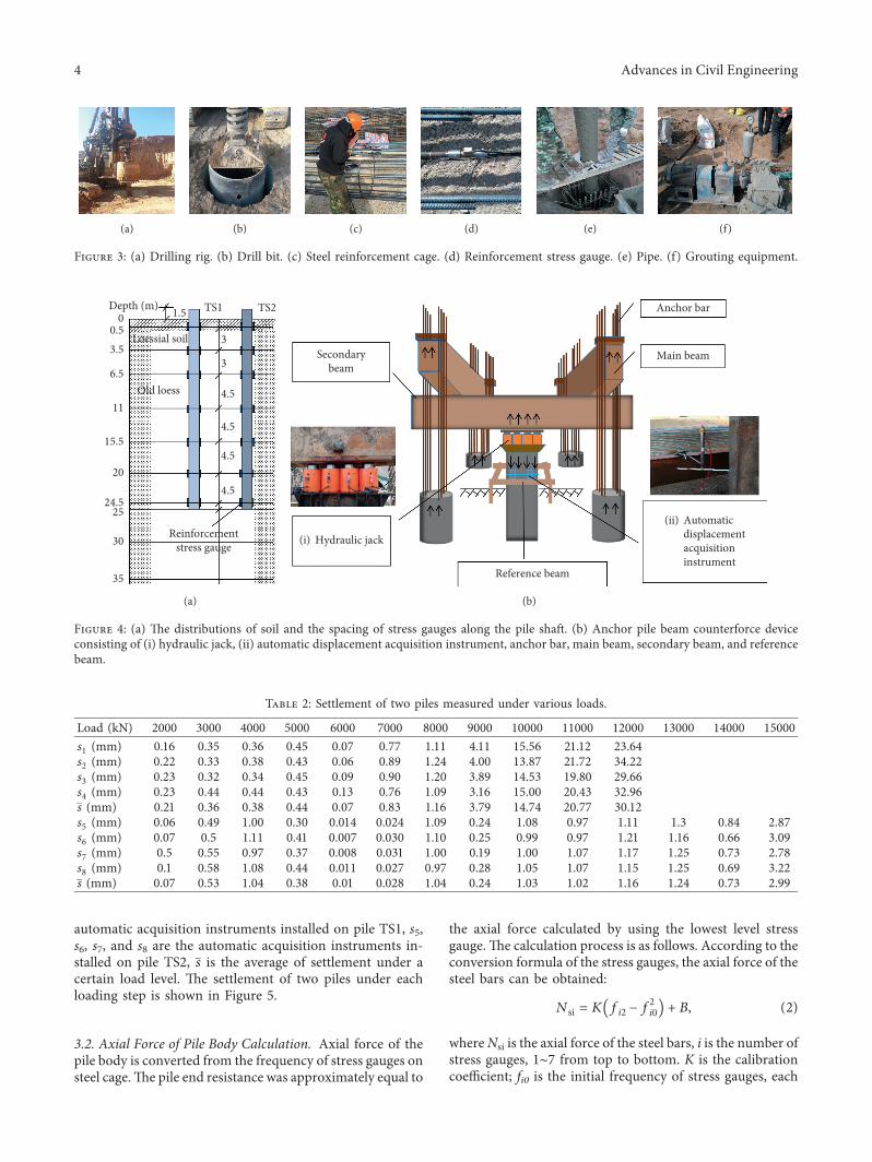
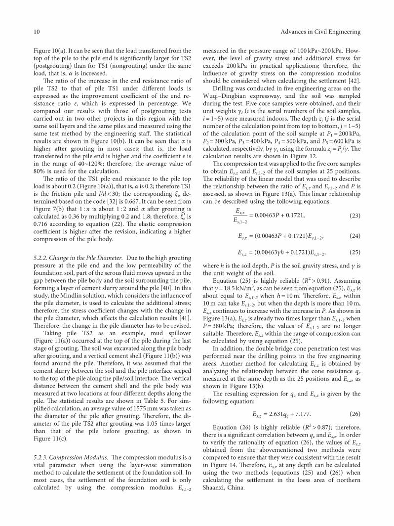
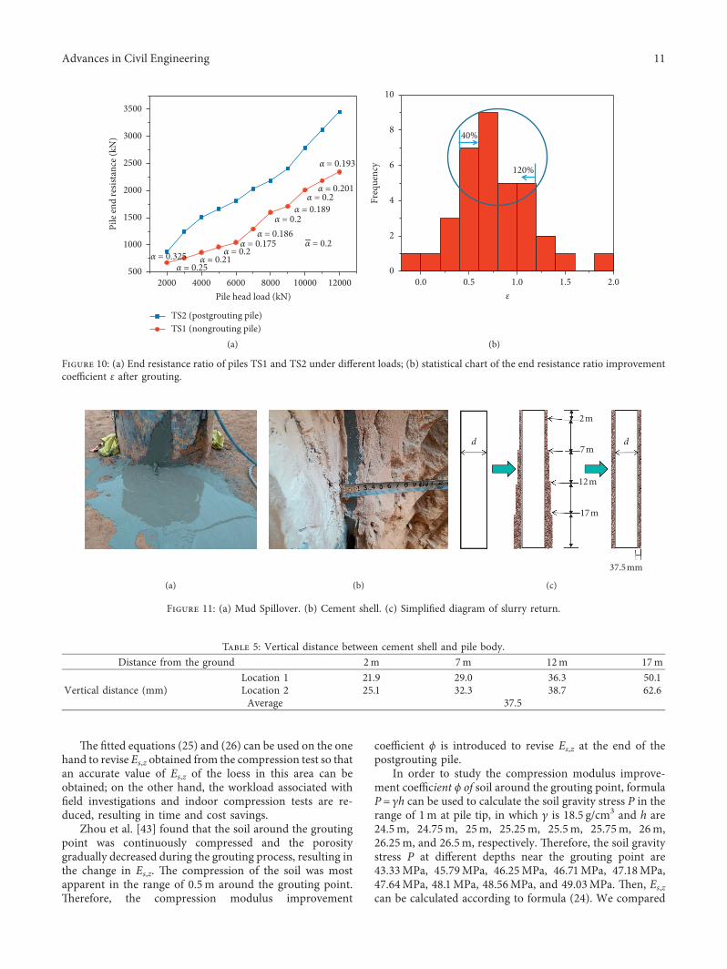
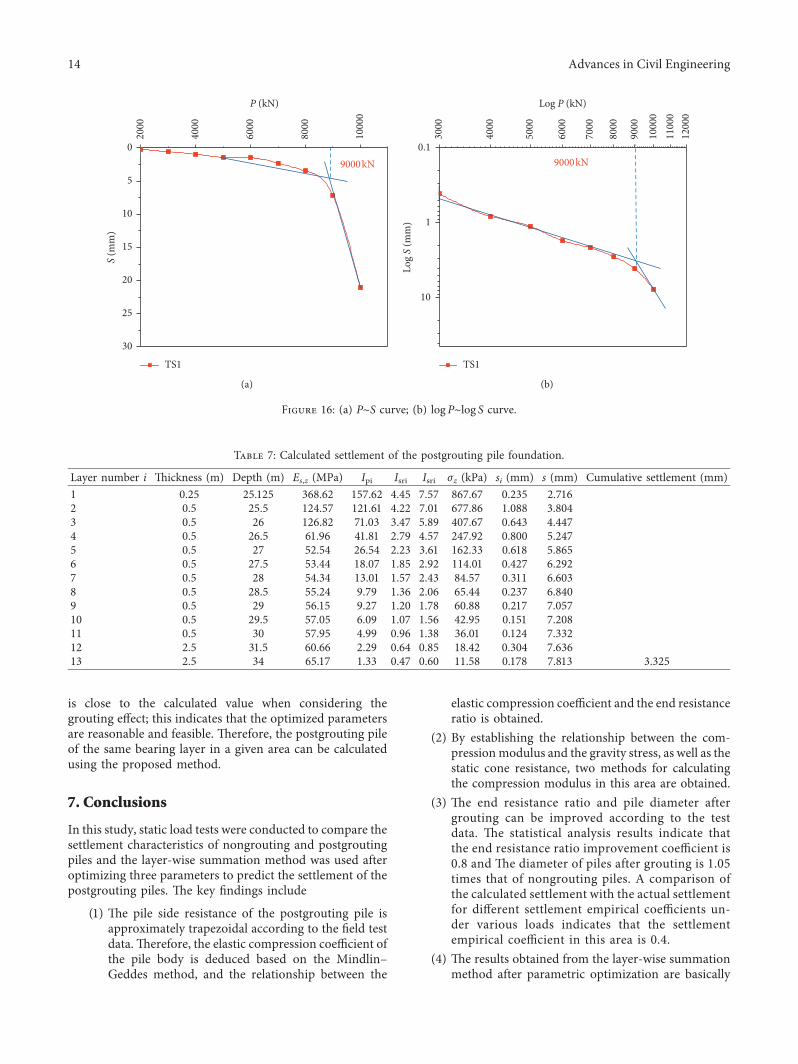

International Journal of
AerospaceEngineeringHindawiwwwhindawicom Volume 2018
RoboticsJournal of
Hindawiwwwhindawicom Volume 2018
Hindawiwwwhindawicom Volume 2018
Active and Passive Electronic Components
VLSI Design
Hindawiwwwhindawicom Volume 2018
Hindawiwwwhindawicom Volume 2018
Shock and Vibration
Hindawiwwwhindawicom Volume 2018
Civil EngineeringAdvances in
Acoustics and VibrationAdvances in
Hindawiwwwhindawicom Volume 2018
Hindawiwwwhindawicom Volume 2018
Electrical and Computer Engineering
Journal of
Advances inOptoElectronics
Hindawiwwwhindawicom
Volume 2018
Hindawi Publishing Corporation httpwwwhindawicom Volume 2013Hindawiwwwhindawicom
The Scientific World Journal
Volume 2018
Control Scienceand Engineering
Journal of
Hindawiwwwhindawicom Volume 2018
Hindawiwwwhindawicom
Journal ofEngineeringVolume 2018
SensorsJournal of
Hindawiwwwhindawicom Volume 2018
International Journal of
RotatingMachinery
Hindawiwwwhindawicom Volume 2018
Modelling ampSimulationin EngineeringHindawiwwwhindawicom Volume 2018
Hindawiwwwhindawicom Volume 2018
Chemical EngineeringInternational Journal of Antennas and
Propagation
International Journal of
Hindawiwwwhindawicom Volume 2018
Hindawiwwwhindawicom Volume 2018
Navigation and Observation
International Journal of
Hindawi
wwwhindawicom Volume 2018
Advances in
Multimedia
Submit your manuscripts atwwwhindawicom