optimization of workplace layout by using simplex method
TRANSCRIPT

Optimization Of Workplace Layout By Using Simplex Method: A Case Study
Kaustubh N. Kalaspurkar1, Ravikant V. Paropate
2, Kapil B. Salve
3, Vaibhav R. Pannase
4
Department of Mechanical Engineering1, 2, 3,4
Jagadamba College of Engineering & Technology, Yavatmal1,4
Jawaharlal Darda Institute of Engineering & Technology, Yavatmal.2,3
.
ABSTRACT:-
Now a day there is competition in market to make available the product in a optimum
quantity and within a forecasted dates with a good quality. To fulfill this condition we need to
install new quality tools available in market which are costly and forced to uninstall the
unnecessary operations. In this paper the case study is discussed which helps to optimize the
workplace layout by using method study & Ergonomics for the human comfort. Case study is
carried out on Assembly of rear axle carrier of a tractor from Automobile Industry.
Key word:- Time and Motion Study, Workstation Design, Ergonomics, Rear Axle Carrier, Stop
Watch.
INTRODUCTION:-
The productivity improvement is the vital part of manufacturing system to satisfy the
market demand which will be based on the efficiency of man i.e. operator is highly depending on
how well the workstation is designed ergonomically, where as the efficiency of machine is more
depends upon its utilization. Whereas the efficiency of both i.e. man and machine is highly
affected by methodology adopted in the manufacturing system. As unnecessary and unproductive
movements and operation will cause the fatigue to operator as well as improper machine
utilization. To analyzed the task in the manufacturing, proper production scheduling is very
important.
2931
International Journal of Engineering Research & Technology (IJERT)
ISSN: 2278-0181
www.ijert.org
Vol. 2 Issue 6, June - 2013
IJERT
IJERT
IJERTV2IS60370
Time study and motion study is widely used in industries. Time study is defined as „It is a
work measurement technique for recording the times and rates of working for the elements of a
specified job carried out under specified conditions, and for analyzing the data so as to determine
the time necessary for carrying out the job at a defined level of performance.‟ Motion study is
defined as „It is the systematic recording and critical examination of existing and proposed ways
of doing work, as a means of developing and applying easier and more effective methods and
reducing costs.‟ In the present work, assembly task at one of the leading tractor manufacturing
company in India is studied to achieve optimum performance evaluation of the productivity. In
the present work the study regarding the workplace layout, number of components involved,
movement of workers, available tools and their location etc. were analyzed.
This layout critically analyzed and found the scope of implementation. In reduction to
time study we have again analyzed the system in total and divided into parts and tried to record
the time for every operation. In flow process chart the analysis of work station has been carried
out and in this analysis we found that in critical analysis helped us to remove unwanted
activities. Work ergonomics study revealed that the Heart rates and total comfort of worker is
higher level as compared to existing one.
Lastly we have tried to check our results through simulation in which we have used
Simulation Software and found very satisfactory and incoming result that our suggested
techniques reduces time and improve the productivity.
LITERATURE REVIEW:-
A significant amount of research work on Time study and Motion study, Modeling and
Simulation, Productivity improvement and Ergonomic study has been published Mr. Gurunath V
Shinde 1, Prof.V.S.Jadhav *2, investigate lots of money on man, machine, material, method
(4m),improving ergonomics of workplaces is cost saving. Ergonomics found great need when
market demand is high and manufacturers need more output within short period. This study was
conducted on assembly workstation of welding shop. This work was conducted on an assembly
station in welding shop. The shop was facing problem of less efficiency of workers due to poor
ergonomics and in some severe cases hazardous health issues are found. This work was
conducted on an assembly station in welding shop. The shop was facing problem of less
2932
International Journal of Engineering Research & Technology (IJERT)
ISSN: 2278-0181
www.ijert.org
Vol. 2 Issue 6, June - 2013
IJERT
IJERT
IJERTV2IS60370
efficiency of workers due to poor ergonomics and in some severe cases hazardous health issues
are found [1]. Baba Md Deros 1 , Nor Kamaliana Khamis 1,Ahmad Rasdan Ismail 2, suggested
the concept of high demand for products in the manufacturing industry had driven the human
workers to work faster and adapt to their un-ergonomically designed workstation. This study was
conducted at an automotive component manufacturer and shows current assembly workstation at
company a need to be redesign to eliminate awkward postures and anthropometric mismatches to
lower MSDs problem and improve productivity among assembly workers [2]. Mr. Gurunath V.
Shinde 1, Prof.V.S.Jadhav 2, identify complex tasks which lead to less efficiency of worker.
Various approaches had been develop including direct observations, questionnaires, interview,
etc. for ergonomic evaluation of workstation. This technique of ergonomic analysis is very useful
to identify complex tasks and root cause of each complex task which is useful in simplifying it
and hence to reduce stress on various workers movements [3]. Ibrahim H. Garbie, investigate the
effects of assembly of a product on operator performance. Workstations for assembly tasks
should be designed so that any operator can adjust to his/her comfort to relieve stress and
improve performance. The main contribution of this work has how to measure the production
rate of manual assembly lines based on design ergonomically assembly workstation [4]. Paul
H.P. Yeowa,_, Rabindra Nath Senb, improving productivity and quality, increasing revenue and
reducing rejection cost of the manual component insertion (MCI) lines in a printed circuit
assembly (PCA) factory. Live experiments were conducted on production lines. Eleven problems
were identified, i.e., long search for materials from the stores, unproductive manual component
counting, obstructions during insertions, component fall-off while the PCA board was traveling
on a U-shaped conveyor, etc. increasing profit for the company owners, providing price
reductions to the customers, and giving large bonus and annual increment to their employees [5].
Ashraf A. Shikdar, Mohamed A. Al-Hadhrami, conducted „Smart workstation design:
an ergonomics and methods engineering approach‟ and this research was to design and develop a
smart workstation for performing industrial assembly tasks. A fully adjustable ergonomically
designed workstation was developed [6]. Javier Santos_, Jose M. Sarriegi, Nicola´ s Serrano,
Jose M. Torres, conducted „Using ergonomic software in non-repetitive manufacturing
processes: A case study‟ This paper uncovers, by means of a case study based on a real process,
the advantages and the practical barriers involved in the implementation of 3D simulation tools
in SMEs. The chosen case study is based on a non-repetitive manufacturing process [7]. D.
2933
International Journal of Engineering Research & Technology (IJERT)
ISSN: 2278-0181
www.ijert.org
Vol. 2 Issue 6, June - 2013
IJERT
IJERT
IJERTV2IS60370
Battini a,*, M. Faccio b, A. Persona a, F. Sgarbossa a, conducted „New methodological
framework to improve productivity and ergonomics in assembly system design‟ this work
analyse how ergonomics and assembly system design techniques are intimately related. It also
develops a new theoretical framework to assess a concurrent engineering approach to assembly
systems design problems, in conjunction with an ergonomics optimization of the workplace. This
work provides an extremely valuable methodological framework to companies who recognize
the link between assembly and ergonomics [8]. Adi Saptari, Wong Soon Lai, Mohd. Rizal
Salleh, conducted „Jig Design, Assembly Line Design and Work Station Design and their Effect
to Productivity‟ the most productive assembly line design which achieved the lowest assembly
time is the combination of one operator, with rectangular jig and work station design sitting. This
assembly station determines the sequences of operations to manufacture of components as well
as the final product [9]. Francesco Longo Giovanni Mirabelli Enrico Papoff, conducted
„EFFECTIVE DESIGN OF AN ASSEMBLY LINE USING MODELING & SIMULATION‟
invented work regarding the effective design of an assembly line for heaters production. The
effective design of assembly line workstations by means of integration between ergonomic
analyses and Modeling & Simulation. Modeling & simulation in combination with ergonomic
analyses is a powerful tool for analyzing assembly line and providing effective design and
optimal ergonomic solutions [10].
PROBLEM IDENTIFICATION AND IMPLEMENTATION
For problem identification time study and motion study technique is used. Using this time
study and motion study technique time required for each operation is calculated by using stop
watch technique for existing setup. After calculating of time for each operation, flow process
chart has been prepared. From study of flow process chart the unwanted activity where critically
analyzed.
Work study, as it stands today to provide us with a scientific approach to investigation
into all form of work, with a view to increase productivity. While many techniques for raising
productivity are available today that qualify as a scientific approach, not all of them fall under
domain of work study. It is one of the tools in the manager‟s tool kit. This is particularly true for
work study where the major focus is the investigation of human work, with an aim to improve
the efficiency of the same.
2934
International Journal of Engineering Research & Technology (IJERT)
ISSN: 2278-0181
www.ijert.org
Vol. 2 Issue 6, June - 2013
IJERT
IJERT
IJERTV2IS60370

Total parts for assembly station 1
Table 1:- Total Parts for Station 1
This study was conducted at a workstation for the assembly of Rear Axle Carrier. This
assembly operation involves 27 components. The entire component was assembled by manual
process. The total assembly process was carried out on three different process stations. The
assembly of the component of each as follows:
Total parts for assembly station 2
Sr. No. Name of Part No. of
Parts
1. Retainer 1
2. Oil Seal 2
3. Gasket 1
4. Axle 1
5. Ball Bearing (Axle) 1
Total Part for Station 1 6
Sr. No Name of Part No. of
Parts
6. Circlip (Rear Axle) 1
7. Pr. Bearing (Carrier) 1
8. Spacer (Carrier) 1
9. Carrier 1
10. Collar 1
11. Bolts 4
12. Washer 4
Total Part for Station 2 13
2935
International Journal of Engineering Research & Technology (IJERT)
ISSN: 2278-0181
www.ijert.org
Vol. 2 Issue 6, June - 2013
IJERT
IJERT
IJERTV2IS60370
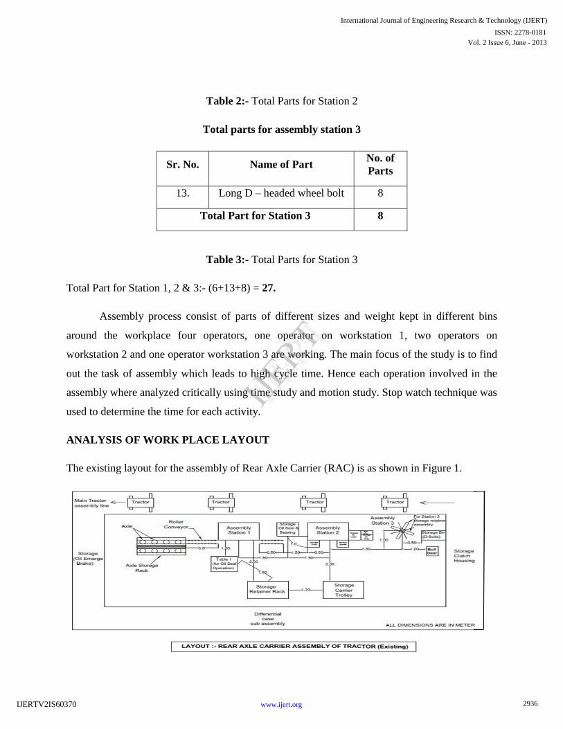
Table 2:- Total Parts for Station 2
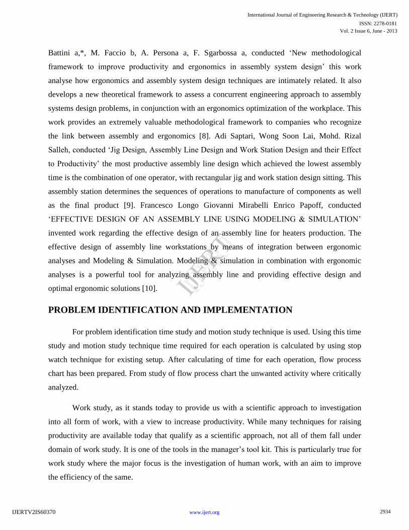
Total parts for assembly station 3
Sr. No. Name of Part No. of
Parts
13. Long D – headed wheel bolt 8
Total Part for Station 3 8
Table 3:- Total Parts for Station 3
Total Part for Station 1, 2 & 3:- (6+13+8) = 27.
Assembly process consist of parts of different sizes and weight kept in different bins
around the workplace four operators, one operator on workstation 1, two operators on
workstation 2 and one operator workstation 3 are working. The main focus of the study is to find
out the task of assembly which leads to high cycle time. Hence each operation involved in the
assembly where analyzed critically using time study and motion study. Stop watch technique was
used to determine the time for each activity.
ANALYSIS OF WORK PLACE LAYOUT
The existing layout for the assembly of Rear Axle Carrier (RAC) is as shown in Figure 1.
2936
International Journal of Engineering Research & Technology (IJERT)
ISSN: 2278-0181
www.ijert.org
Vol. 2 Issue 6, June - 2013
IJERT
IJERT
IJERTV2IS60370

Fig. 1:- Rear Axle Carrier Assembly of Tractor (Existing)
As shown in Figure No. 1 it consists of three in line assembly workstation namely station
1, 2 and 3. Material flow was successive from station 1 to station 2 then from station 2 to station
3. To assist the operator for the material flow roller conveyor (manually operated), and cranes
are used.
Assembly operation at station 1 involves the assembly of 6 components as shown in table
no.1 out of which retainers are stores in the retainer rack which was located just behind the
operator as shown in Fig. No.1. Also the oil seal, gasket, bearing and the axle are located
surrounding the workplace as shown in Fig. No.1. During each assembly operator has to move at
each of these locations and collects the parts for the assembly. Similarly the components required
assembly station 2 and 3 is to be connected by the operator from the various storage locations
surrounding the workplace as shown in the Fig. No.1.
FLOW PROCESS CHARTS
From the above workplace layout and the nature of assembly involved requires several
activity at each station 1, 2 and 3. For example at assembly station 1 total 51 activities of the
time 6.04 min are involved. At assembly station 2 total 38 activities of the time 5.21 min and 24
activities of the 4.02 min are involves at station 3. Accordingly the flow process chart of the
material for each of the assembly station is developed. The sample flow process chart for station
1 is shown in Table No. 4.
FLOW PROCESS CHART - MATERIAL TYPE (STATION 1)
FLOW PROCESS CHART MATERIAL TYPE
CHART NO. SHEET NO. SUMMARY
Subject charted
Used bus engines
ACTIVITY PRESENT PROPOSE
D SAVING
OPERATION 38 34 04
2937
International Journal of Engineering Research & Technology (IJERT)
ISSN: 2278-0181
www.ijert.org
Vol. 2 Issue 6, June - 2013
IJERT
IJERT
IJERTV2IS60370

ACTIVITY
Stripping cleaning and degreasing prior to
inspection
METHOD: PRESENT
TRANSPORT
DELAY
INSPECTION
STORAGE
08
02
01
02
05
02
01
02
03
-
-
-
DISTANCE (m) - - -
LOCATION: Degreasing Shop TIME (man-min) - - -
OPERATIVE(S): CLOCK Nos.
COST
LABOUR
MATERIAL
-
-
-
-
-
-
-
-
- CHARTED BY:
APPROVED BY: DATE: TOTAL - - -
DESCRIPTION QTY
DISTAN
CE
(m)
TIME
(sec) SYMBOL
REMAR
KS
1. Retainer stored in trolley near
assembly station 1 - 00
2. Pickup the retainer from
retainer rack - 6.82
3. Move to table 1 1.5 11.64
4. Pickup the oil seal from table
1 - 6.48
5. Move retainer and oil seal to
assembly station 1 1.0 9.81
6. Placed the oil seal on station
1 - 7.79
TABLE 4:- Sample Flow Process Chart - Material Type (Assembly Station 1)
2938
International Journal of Engineering Research & Technology (IJERT)
ISSN: 2278-0181
www.ijert.org
Vol. 2 Issue 6, June - 2013
IJERT
IJERT
IJERTV2IS60370
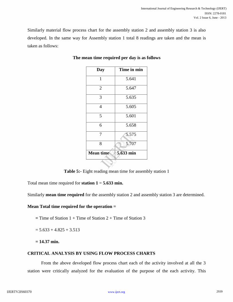
Similarly material flow process chart for the assembly station 2 and assembly station 3 is also
developed. In the same way for Assembly station 1 total 8 readings are taken and the mean is
taken as follows:
The mean time required per day is as follows
Day Time in min
1 5.641
2 5.647
3 5.635
4 5.605
5 5.601
6 5.658
7 5.575
8 5.707
Mean time 5.633 min
Table 5:- Eight reading mean time for assembly station 1
Total mean time required for station 1 = 5.633 min.
Similarly mean time required for the assembly station 2 and assembly station 3 are determined.
Mean Total time required for the operation =
= Time of Station 1 + Time of Station 2 + Time of Station 3
= 5.633 + 4.825 + 3.513
= 14.37 min.
CRITICAL ANALYSIS BY USING FLOW PROCESS CHARTS
From the above developed flow process chart each of the activity involved at all the 3
station were critically analyzed for the evaluation of the purpose of the each activity. This
2939
International Journal of Engineering Research & Technology (IJERT)
ISSN: 2278-0181
www.ijert.org
Vol. 2 Issue 6, June - 2013
IJERT
IJERT
IJERTV2IS60370
evaluation is done by finding the answers to the Primary and Secondary questions such as what
is achieved through that activity, is that activity is necessary, can it be eliminated, what else
might be done etc. from this critically analysis unnecessary and unproductive activities for the
assembly operation at each of the workstation is determined. Accordingly the critical analysis
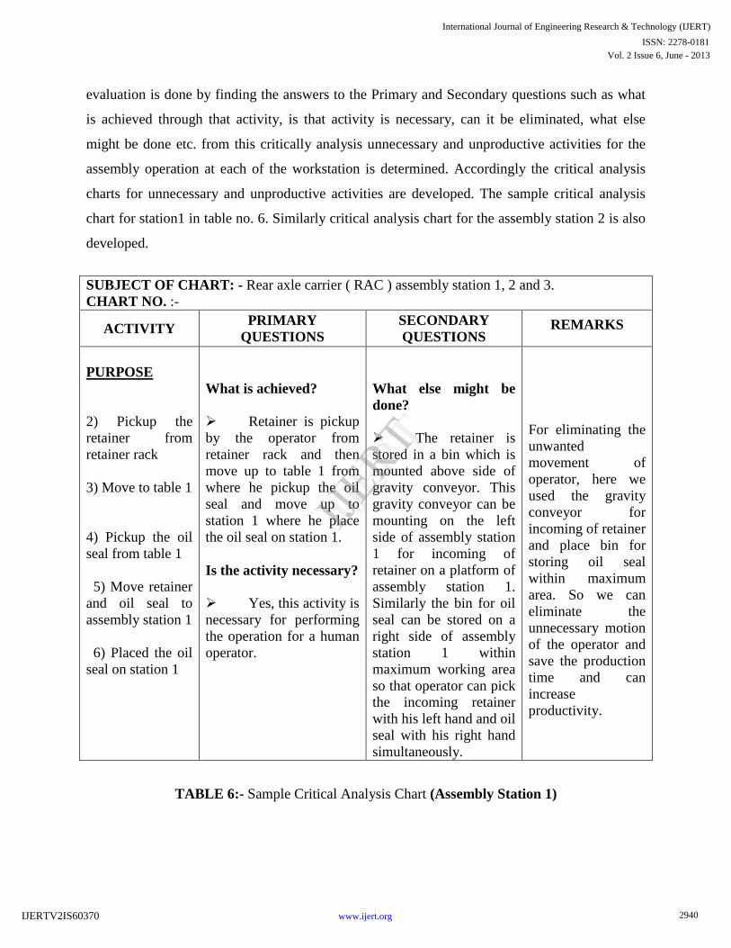
charts for unnecessary and unproductive activities are developed. The sample critical analysis
chart for station1 in table no. 6. Similarly critical analysis chart for the assembly station 2 is also
developed.
SUBJECT OF CHART: - Rear axle carrier ( RAC ) assembly station 1, 2 and 3.
CHART NO. :-
ACTIVITY PRIMARY
QUESTIONS
SECONDARY
QUESTIONS REMARKS
PURPOSE
2) Pickup the
retainer from
retainer rack
3) Move to table 1
4) Pickup the oil
seal from table 1
5) Move retainer
and oil seal to
assembly station 1
6) Placed the oil
seal on station 1
What is achieved?
Retainer is pickup
by the operator from
retainer rack and then
move up to table 1 from
where he pickup the oil
seal and move up to
station 1 where he place
the oil seal on station 1.
Is the activity necessary?
Yes, this activity is
necessary for performing
the operation for a human
operator.
What else might be
done?
The retainer is
stored in a bin which is
mounted above side of
gravity conveyor. This
gravity conveyor can be
mounting on the left
side of assembly station
1 for incoming of
retainer on a platform of
assembly station 1.
Similarly the bin for oil
seal can be stored on a
right side of assembly
station 1 within
maximum working area
so that operator can pick
the incoming retainer
with his left hand and oil
seal with his right hand
simultaneously.
For eliminating the
unwanted
movement of
operator, here we
used the gravity
conveyor for
incoming of retainer
and place bin for
storing oil seal
within maximum
area. So we can
eliminate the
unnecessary motion
of the operator and
save the production
time and can
increase
productivity.
TABLE 6:- Sample Critical Analysis Chart (Assembly Station 1)
2940
International Journal of Engineering Research & Technology (IJERT)
ISSN: 2278-0181
www.ijert.org
Vol. 2 Issue 6, June - 2013
IJERT
IJERT
IJERTV2IS60370

PROPOSED IMPROVEMENT IN THE WORKPLACE LAYOUT
On the critical analysis for assembly station 1 it was found that activity no. 2, 3, 4, 5, 6,
39, and 40 where unnecessary and can be replaced by making certain suitable arrangement in the
workplace layout. For example activity no. 2 to 6 involves movement of the worker from the
workstation to the storage location for picking and transporting retainers and oil seals to
assembly station 1. This amount of the worker can be eliminated by gravity conveyor for the
retainer located near the station 1 which will make constant supply of retainer at the assembly
station; similarly special storage bin for the oil seal can be located within the reach of the
operator near the assembly station 1. This will eliminate the need of movement of worker for
each assembly operation and will result in saving of time. Similarly activity 39 and 40 involved
movement and pickup of the bearing of the worker. This unnecessary movement can be
eliminated in similar way by making provision of storage bin of bearing nearer to assembly
station 1. Similarly for the station 2 and station 3 unnecessary activities were found out and they
are eliminated by making required alteration in the workplace. This activity was consuming the
total time of 1.481 min. These are tabulated below:
Previous layout:-
From this table it is seen that
Station Operation No. Description for Existing layout
Station 1
Operation 2 Pickup the retainer from retainer rack
Operation 3 Move to table 1
Operation 4 Pickup the oil seal from table 1
Operation 5 Move retainer and oil seal to assembly station 1
Operation 6 Placed the oil seal on station 1
Operation 39 Pick up the bearing on table 1
Operation 40 Move bearing to station 1
Station 2 Operation 58 Pick up the bearing from storage (labour 2)
Operation 59 Move bearing to assembly station 2 (labour 2)
2941
International Journal of Engineering Research & Technology (IJERT)
ISSN: 2278-0181
www.ijert.org
Vol. 2 Issue 6, June - 2013
IJERT
IJERT
IJERTV2IS60370
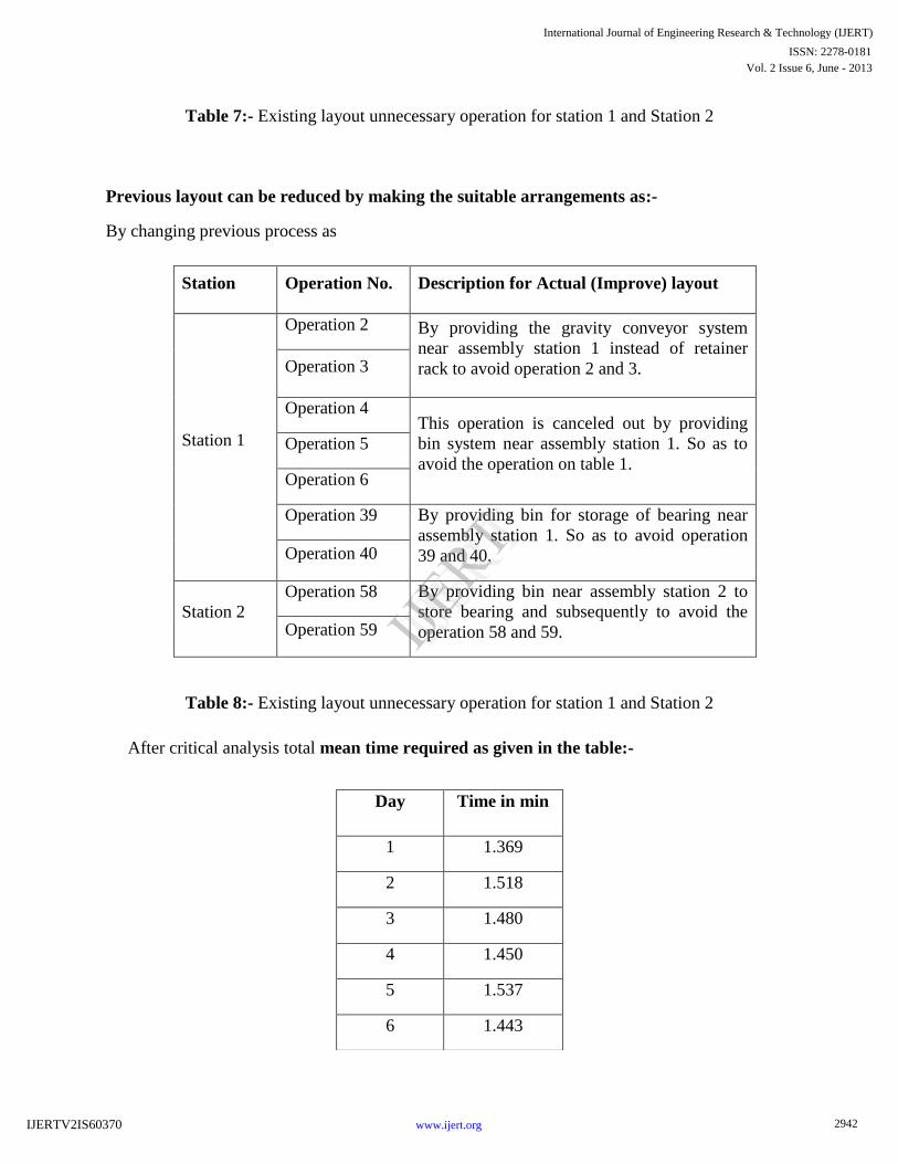
Table 7:- Existing layout unnecessary operation for station 1 and Station 2
Previous layout can be reduced by making the suitable arrangements as:-
By changing previous process as
Station Operation No. Description for Actual (Improve) layout
Station 1
Operation 2 By providing the gravity conveyor system
near assembly station 1 instead of retainer
rack to avoid operation 2 and 3. Operation 3
Operation 4 This operation is canceled out by providing
bin system near assembly station 1. So as to
avoid the operation on table 1.
Operation 5
Operation 6
Operation 39 By providing bin for storage of bearing near
assembly station 1. So as to avoid operation
39 and 40. Operation 40
Station 2
Operation 58 By providing bin near assembly station 2 to
store bearing and subsequently to avoid the
operation 58 and 59. Operation 59
Table 8:- Existing layout unnecessary operation for station 1 and Station 2
After critical analysis total mean time required as given in the table:-
Day Time in min
1 1.369
2 1.518
3 1.480
4 1.450
5 1.537
6 1.443
2942
International Journal of Engineering Research & Technology (IJERT)
ISSN: 2278-0181
www.ijert.org
Vol. 2 Issue 6, June - 2013
IJERT
IJERT
IJERTV2IS60370
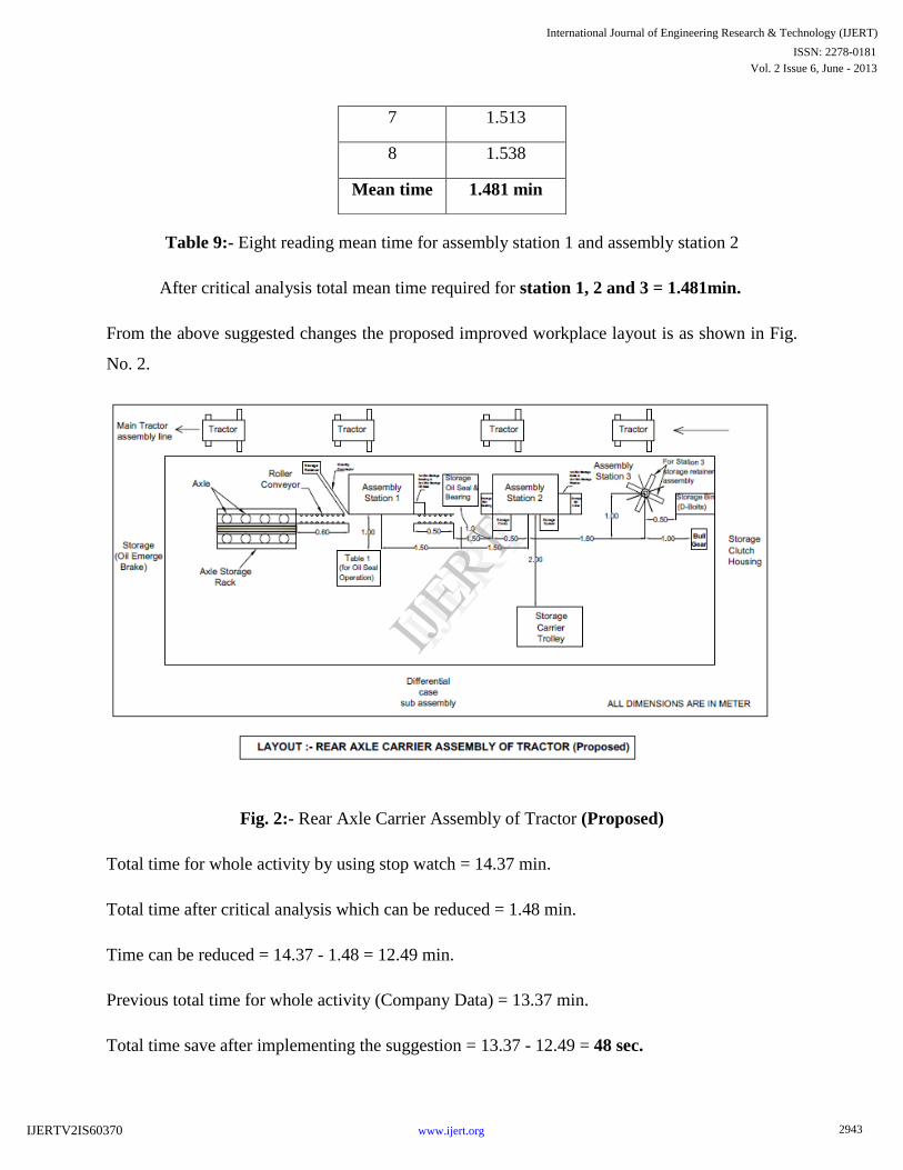
Table 9:- Eight reading mean time for assembly station 1 and assembly station 2
After critical analysis total mean time required for station 1, 2 and 3 = 1.481min.
From the above suggested changes the proposed improved workplace layout is as shown in Fig.
No. 2.
Fig. 2:- Rear Axle Carrier Assembly of Tractor (Proposed)
Total time for whole activity by using stop watch = 14.37 min.
Total time after critical analysis which can be reduced = 1.48 min.
Time can be reduced = 14.37 - 1.48 = 12.49 min.
Previous total time for whole activity (Company Data) = 13.37 min.
Total time save after implementing the suggestion = 13.37 - 12.49 = 48 sec.
7 1.513
8 1.538
Mean time 1.481 min
2943
International Journal of Engineering Research & Technology (IJERT)
ISSN: 2278-0181
www.ijert.org
Vol. 2 Issue 6, June - 2013
IJERT
IJERT
IJERTV2IS60370
Total time saves for 8 hour shift:-
Total time save after implementing the suggestion for one RAC assembly = 48 sec.
Total time save for assembly of two RAC assembly = 1.36 min.
For 8 hour shift 70 tractors assemble.
Total time optimize (1.36 x 70) = 1 hour 35 min time save for 8 hour shift.
ERGONOMICS CONSIDERATION
„It is scientific, in that Ergonomists measure human characteristics and human function, and
establish the way that human body and human mind work. It is also technological, in that the
results of scientific work in the human sciences are applied by ergonomists in the solution of
practical problems in the design and manufacture of products and system‟.
For Ergonomics we have count the Heart Rate of worker. From Heart Rate reading, by using
formula we calculate Oxygen Consumption and Energy Consumption reading of worker for
Existing Layout. After making some improvement in layout of Existing Rear Axle Carrier
(RAC). There is reduction in Heart Rate count and accordingly there is less Oxygen and Energy
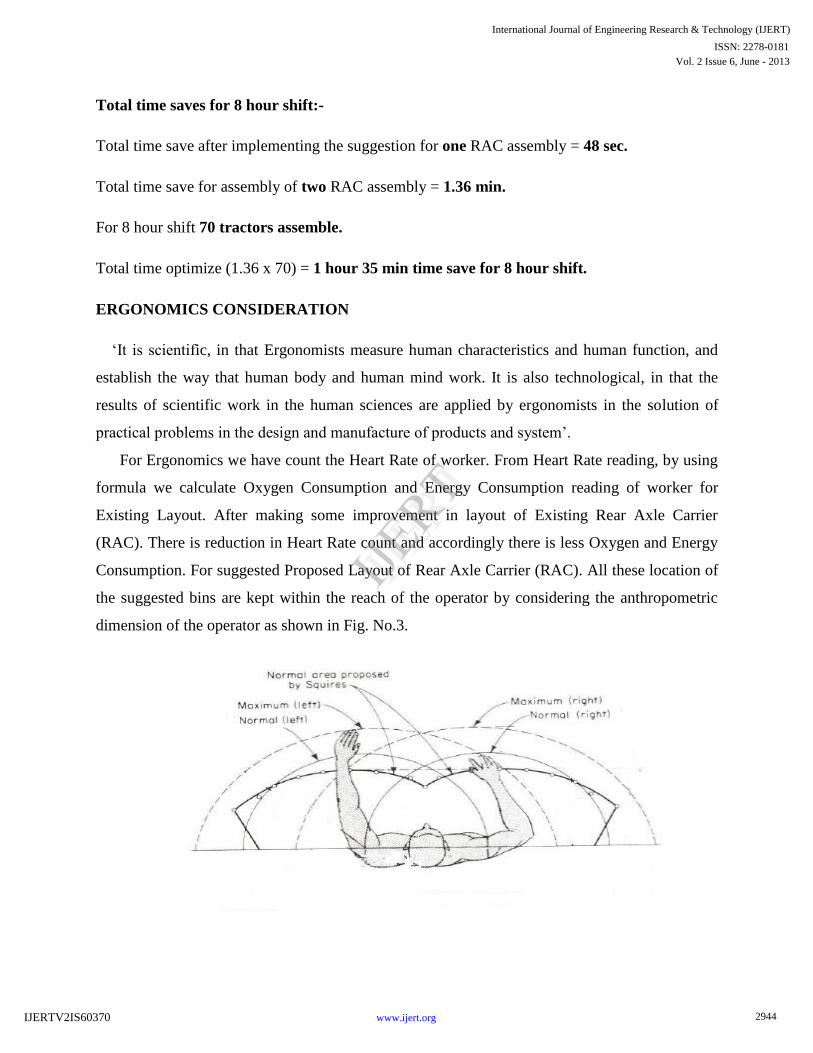
Consumption. For suggested Proposed Layout of Rear Axle Carrier (RAC). All these location of
the suggested bins are kept within the reach of the operator by considering the anthropometric
dimension of the operator as shown in Fig. No.3.
2944
International Journal of Engineering Research & Technology (IJERT)
ISSN: 2278-0181
www.ijert.org
Vol. 2 Issue 6, June - 2013
IJERT
IJERT
IJERTV2IS60370

Fig. 3:- Recommended working distance for the arms
For the ergonomic consideration we count the heart rate reading of a worker for both the
condition ,after counting it is observed that in the suggested improvement condition the heart rate
readings are minimum than previous. Following graph shows the decrease in heart rate of
suggested changes in workplace layout of RAC assembly.
Fig. 4:- Existing condition heart rate reading
2945
International Journal of Engineering Research & Technology (IJERT)
ISSN: 2278-0181
www.ijert.org
Vol. 2 Issue 6, June - 2013
IJERT
IJERT
IJERTV2IS60370

Fig. 5:- Proposed condition heart rate reading
RESULT AND DISCUSSION
OPTIMIZATION THROUGH SIMPLEX METHOD
In the simplex method we have optimize the time for existing work layout and the
proposed work layout. The simplex method in which we have obtained the result for minimizing
time and improve the production. This result calculated by using simplex method for existing
layout and proposed layout.
The optimal solution for existing layout is reached with S1 = 0, X1 = 5.633, and S3 = 0.
Zmax = 0 X 5.39 + 5.633 X 2.93 + 0 X 7.78
= 16.50 …..(For existing layout completing operation for assembly station 1 maximum time
required is 16.50.)
The optimal solution for proposed layout is reached with X1 = 4.5, X2 = 4.32, and S3 = 0.
Zmax = 4.5 X 1.003 + 4.32 X 2.06 + 0 X 1.48
2946
International Journal of Engineering Research & Technology (IJERT)
ISSN: 2278-0181
www.ijert.org
Vol. 2 Issue 6, June - 2013
IJERT
IJERT
IJERTV2IS60370

= 13.41 …..(For proposed layout completing operation for assembly station 1 and assembly
station 2 maximum time required is 13.41.)
For existing layout completing operation for assembly station 1 maximum time required
is Zmax = 16.50 and for proposed layout completing operation for assembly station 1 and
assembly station 2 maximum time required is Zmax = 13.41. By solving optimization through
simplex method we have tried for increasing the production rate for proposed layout.
COMPARISON BETWEEN EXISTING LAYOUT AND PROPOSE LAYOUT BY USING
SIMPLEX METHOD
In this present work we have suggested to incorporate new improved layout in which the
production rate per day for assembling component for assembly station one and assembly station
two is maximize up to certain level without disturbing another assembly station or production
layout unit. In this work we have found that the production rate is very much depends on
travelling time of assemble component. So by reducing the extra time and extra effort we have
found this result for the optimize layout. Overall increases the production rate as compare to
existing one.
The time consume in existing layout is maximum as where the time consume in proposed
layout is minimum up to a certain level. The existing layout required the maximum time of Zmax
= 16.50 while for proposed layout it would be found Zmax = 13.41.
CONCLUSION
In my project work in which I have theoretically studied time study, motion study and
ergonomics on the leading tractor manufacturing company. The result I found in critical analysis
is that by the time study and motion study some of the unnecessary operations are combined and
modified the flow process in proposed one helps us to reduce time by certain modification in
nearby assembly station.
These said modifications in workplace layout are designed ergonomically as well.
With this improved layout the total time 48 sec per cycle was found to be reduced. Hence the
above result helped us to reduce time and motion ultimately improves production.
2947
International Journal of Engineering Research & Technology (IJERT)
ISSN: 2278-0181
www.ijert.org
Vol. 2 Issue 6, June - 2013
IJERT
IJERT
IJERTV2IS60370

LITERATURE CITED:-
[1] Mr. Gurunath V Shinde1, Prof. V. S. Jadhav , “Ergonomic analysis of an assembly
workstation to identify time consuming and fatigue causing factors using application of motion
study”, International Journal of Engineering and Technology (IJET), ISSN : 0975-4024 Vol 4 No
4 Aug Sep 2012.
[2] 1Baba Md Deros, 1Nor Kamaliana Khamis, 2Ahmad Rasdan Ismail, , “An Ergonomics Study
on Assembly Line Workstation Design”, American Journal of Applied Sciences 8 (11): 1195-
1201, 2011, ISSN 1546-9239, © 2011 Science Publications.
[3] Mr. Gurunath V. Shinde1, Prof. V. S. Jadhav2 , “A Computer based novel approach of
ergonomic study and analysis of a workstation in a manual process”, International Journal of
Engineering Research & Technology (IJERT) Vol. 1 Issue 6, August – 2012, ISSN: 2278-0181.
[4] Ibrahim H. Garbie, “AN EXPERIMENTAL STUDY ON ASSEMBLY WORKSTATION
CONSIDERING ERGONOMICALLY ISSUES”, Proceedings of the 41st International
Conference on Computers & Industrial Engineering.
[5] Yeow P.H.P., Sen R.N., (2006), “Productivity and quality improvements, revenue increment,
and rejection cost reduction in the manual component insertion lines through the application of
ergonomics” International Journal of Industrial Ergonomics 36:367–377.
[6] Shikdar A., Al-Hadhrami M.,( 2007 ). “Smart workstation design: an ergonomics and
methods engineering approach.” International Journal of Industrial and Systems Engineering.
2(4), 363-374.
[7] Santos J, Sarriegi J.M.( 2007). “Using ergonomic software in non-repetitive manufacturing
processes: A case study”. International Journal of Industrial Ergonomics 37: 267-275.
[8] Battini D., Faccio M., (2011), “New methodological framework to improve productivity and
ergonomics in assembly system design”, International Journal of industrial ergonomics 41 (30-
32).
2948
International Journal of Engineering Research & Technology (IJERT)
ISSN: 2278-0181
www.ijert.org
Vol. 2 Issue 6, June - 2013
IJERT
IJERT
IJERTV2IS60370

[9] Adi Saptari, Wong Soon Lai, Mohd. Rizal Salleh, “Jig Design, Assembly Line Design and
Work Station Design and their Effect to Productivity”, 2011 Jordan Journal of Mechanical and
Industrial Engineering. All rights reserved - Volume 5, Number 1 (ISSN 1995-6665)
[10] Francesco Longo, Giovanni Mirabelli, Enrico Papoff, “EFFECTIVE DESIGN OF AN
ASSEMBLY LINE USING MODELING & SIMULATION”, Proceedings of the 2006 Winter
Simulation Conference, L. F. Perrone, F. P. Wieland, J. Liu, B. G. Lawson, D. M. Nicol, and R.
M. Fujimoto, eds.
2949
International Journal of Engineering Research & Technology (IJERT)
ISSN: 2278-0181
www.ijert.org
Vol. 2 Issue 6, June - 2013
IJERT
IJERT
IJERTV2IS60370