optimization of multimedia codecs using arm neon of multimedia codecs using... · optimization of...
TRANSCRIPT
Optimization of Multimedia Codecs using ARM NEON
1 Incube Solutions Pvt. Ltd
Optimization of Multimedia Codecs using ARM NEON
This paper discusses how multimedia codecs can be optimized on ARM cortex A series microprocessors using NEON technology. Incube solutions
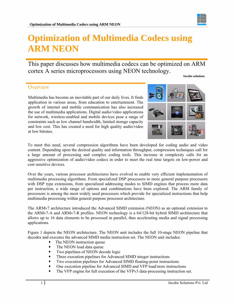
Overview Multimedia has become an inevitable part of our daily lives. It finds application in various areas, from education to entertainment. The growth of internet and mobile communication has also increased the use of multimedia applications. Digital audio/video applications for network, wireless-enabled and mobile devices pose a range of constraints such as low channel bandwidth, limited storage capacity and low cost. This has created a need for high quality audio/video at low bitrates.
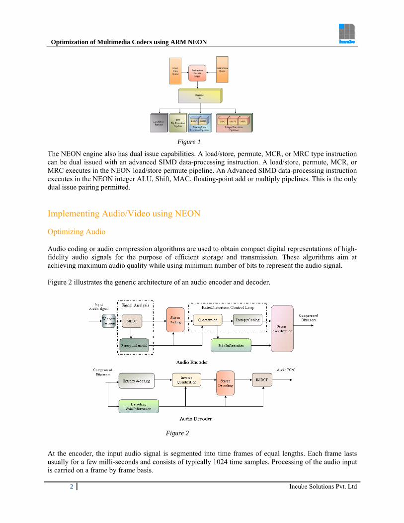
To meet this need, several compression algorithms have been developed for coding audio and video content. Depending upon the desired quality and information throughput, compression techniques call for a large amount of processing and complex coding tools. This increase in complexity calls for an aggressive optimization of audio/video codecs in order to meet the real time targets on low-power and cost sensitive devices. Over the years, various processor architectures have evolved to enable very efficient implementation of multimedia processing algorithms. From specialized DSP processors to more general purpose processors with DSP type extensions, from specialized addressing modes to SIMD engines that process more data per instruction, a wide range of options and combinations have been explored. The ARM family of processors is among the most widely used processors which provide for specialized instructions that help multimedia processing within general purpose processor architecture. The ARMv7 architecture introduced the Advanced SIMD extension (NEON) as an optional extension to the ARMv7-A and ARMv7-R profiles. NEON technology is a 64/128-bit hybrid SIMD architecture that allows up to 16 data elements to be processed in parallel, thus accelerating media and signal processing applications. Figure 1 depicts the NEON architecture. The NEON unit includes the full 10-stage NEON pipeline that decodes and executes the advanced SIMD media instruction set. The NEON unit includes:
The NEON instruction queue The NEON load data queue Two pipelines of NEON decode logic Three execution pipelines for Advanced SIMD integer instructions Two execution pipelines for Advanced SIMD floating-point instructions One execution pipeline for Advanced SIMD and VFP load/store instructions The VFP engine for full execution of the VFPv3 data-processing instruction set.
Optimization of Multimedia Codecs using ARM NEON
2 Incube Solutions Pvt. Ltd
Figure 1
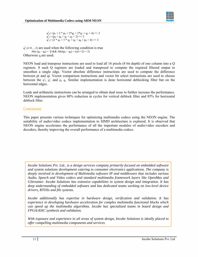
The NEON engine also has dual issue capabilities. A load/store, permute, MCR, or MRC type instruction can be dual issued with an advanced SIMD data-processing instruction. A load/store, permute, MCR, or MRC executes in the NEON load/store permute pipeline. An Advanced SIMD data-processing instruction executes in the NEON integer ALU, Shift, MAC, floating-point add or multiply pipelines. This is the only dual issue pairing permitted. Implementing Audio/Video using NEON Optimizing Audio Audio coding or audio compression algorithms are used to obtain compact digital representations of high-fidelity audio signals for the purpose of efficient storage and transmission. These algorithms aim at achieving maximum audio quality while using minimum number of bits to represent the audio signal. Figure 2 illustrates the generic architecture of an audio encoder and decoder.
Figure 2
At the encoder, the input audio signal is segmented into time frames of equal lengths. Each frame lasts usually for a few milli-seconds and consists of typically 1024 time samples. Processing of the audio input is carried on a frame by frame basis.

Optimization of Multimedia Codecs using ARM NEON
3 Incube Solutions Pvt. Ltd
The input frame first enters the signal analysis stage and the psychoacoustic stage. The MDCT transforms the signal into a frequency domain representation and the psychoacoustic model applies rules from psychoacoustics to identify perceptual irrelevancies. The output from both the MDCT and psychoacoustic stage then goes to the quantization and encoding stage where the actual coding occurs. The quantization and entropy coding stage decides how bits are allocated among the spectral coefficients and a quantizer is used to (re)quantize them. Sometimes, an additional coding step like joint stereo coding is applied at this stage to further remove statistical redundancy. The quantized coefficients, along with some side information, are finally formatted into the output bitstream. The decoder, on the receiving end, simply performs the reverse operations to generate an audio output. Each of the above stages involves complex computations to process the audio stream and compress it into bitstream format. Some of the major compute intensive parts of the audio coder and the techniques to optimize their implementations using NEON engine are described below. Filtering Most audio and speech processing involves analysis and processing of signals in different frequency ranges. Hence filters are extensively used in audio processing at a variety of places like e.g., transient detection, noise reduction, audio effects like bass boost, equalizers etc. Mathematically, filtering is implemented as a convolution of two sequences. A typical FIR filter can be expressed in the form of the following equation
Where x[n] is the input sample and y[n] is the filtered output sample. An IIR filter has an additional feedback component where previous output values are also added along with the previous input values. The equation for an IIR filter is
Where x[n] is the input sample and y[n] is the filtered output sample. Figure 3 shows the data dependencies in case of both FIR and IIR filters. It can be seen that previous input values and previous output values are sequentially multiplied with the coefficients to generate an output value.
Figure 3
NEON instructions can be used to parallelize the loading of coefficients and data samples and multiplying them. Figure 4 depicts how NEON instructions can be used to implement this operation.

Optimization of Multimedia Codecs using ARM NEON
4 Incube Solutions Pvt. Ltd
Figure 4
As the filter coefficients are constant for all computations, they are loaded into the corresponding vector registers only once and used for the computation of every output sample. Vector registers containing the data samples must be loaded with the required data and multiplied with the coefficient vector to generate output data. Vector multiplication instructions operate on quad-registers and pair-wise add instruction is used to add the product results into a double-register as shown in the figure. In case of an FIR filter, multiple outputs can be computed in parallel so that the stores to the output buffer are vectorized. This is not possible for an IIR filter as the next output depends on the current output data. Arrangement of vector loads and vector arithmetic instructions (multiply/add) to suit dual issue also gives reduction in cycles. Optimizing an FIR filter implementation using NEON results in around 40% reduction in cycles. Time to Frequency Mapping The time to frequency mapping is incorporated into an audio encoder for signal analysis and efficient data compaction. A modulated lapped transform, also known as MDCT is used for this mapping. MDCT is performed on consecutive blocks of the input data, where subsequent blocks are overlapped so that the last half of one block coincides with the first half of the next block. This overlapping helps to avoid artifacts stemming from the block boundaries. The samples are first windowed before applying transforms like DFT, DCT etc. At the decoder, the decoded spectral coefficients are inverse transformed and the resulting time sequence is multiplied by a synthesis window, overlapped and added to generate the reconstructed signal. Windowing Windowing is done to avoid discontinuities at block boundaries. Window shape and size decisions are made by the encoder on a frame-by-frame basis. Windowing a block of data involves applying a window function to the data samples. The window function values are stored in memory as a table. For each frame, the window values are loaded and multiplied with the frame samples. Since the table values and the frame samples are contiguously stored in memory, vectorizing the windowing and overlap-add implementation would reduce the number of cycles. Figure 5 shows two quad registers, one loaded with window coefficients and the other with data samples.
Figure 5

Optimization of Multimedia Codecs using ARM NEON
5 Incube Solutions Pvt. Ltd
A vector multiply instruction multiplies the corresponding data elements in these two registers and places the product in another quad register. NEON provides alignment qualifiers that can be added to vector loads/stores to reduce extra cycles to access memory. To use these alignment qualifiers, the memory accessed should be aligned to the required number of bytes. For example, Figure 5 shows four 32-bit wide data elements loaded into a quad register. The memory from where the data samples or the window coefficients are loaded can be aligned to 128-bit for an improved load/store performance. Implementing the windowing operation using NEON will give 80% reduction in cycles. MDCT To transform the windowed time domain samples into spectral coefficients, MDCT is applied. To accelerate the MDCT computation, the transform is implemented using FFT combined with pre-post processing steps. The pre-processing and post-processing steps are similar to windowing and can be vectorized to reduce clock cycles. Figure 6 explains how data level parallelism can be exploited to make use of NEON instructions to implement FFT. For the ease of illustration, Radix-2 FFT is chosen.
Figure 6
Interleaved loads are used to extract even and odd parts of the input sample sequence into the vector registers. Vector multiplication is used for twiddle factor multiplication. Vector adds and subtracts are used for the butterfly operation. De-interleaving and swapping operations are used to arrange data in the required order before each stage. Since a single vector instruction is needed to compute four values in parallel, a significant gain in the clock cycles can be observed. Loads and arithmetic instructions can be arranged to obtain dual issue to further increase the performance. Further gain is achieved by aligning the required buffers to 128-bit and adding alignment qualifiers to the

Optimization of Multimedia Codecs using ARM NEON
6 Incube Solutions Pvt. Ltd
vector load/store instructions. By implementing Radix-4 FFT using NEON, a 50% reduction in cycles is obtained. Perceptual model A perceptual model is another essential tool used by the encoder during signal analysis. It is used to achieve coding gain by exploiting perceptual irrelevancies and statistical redundancies in an audio signal. To identify the irrelevant information in an audio signal, the perceptual model incorporates several psychoacoustic principles into an encoder such as absolute thresholds of hearing, critical band frequency analysis, simultaneous masking, the spread of masking along the basilar membrane, and temporal masking. The psychoacoustic threshold which defines an upper limit for the quantization noise is calculated using band energies. The energy computation essentially involves squaring each spectral coefficient and summing them over a band. These set of operations are similar to those used in filtering. Hence, NEON vector instructions such as vector loads, vector multiply and pair-wise adds can be used to efficiently optimize the energy calculation. Some audio encoders use additional noise shaping tools to increase the apparent signal to noise ratio of the coded signal. An important step in noise shaping algorithms is the autocorrelation operation. Like the energy calculation, autocorrelation also involves sequential multiplication operations which can be implemented using vector multiplication instructions for efficient optimization. Stereo coding Joint stereo coding is an extension of the perceptual model that takes advantage of the typical high correlation that exists between the signal power spectra of the left and right in stereo audio, to improve coding gain. There are various ways of achieving this:
(i) Mid-Side (M/S) stereo: In this method, instead of transmitting the left and right channels, the normalized sum (mid) and difference (side) signals are transmitted. To optimize this implementation, this operation can be performed using NEON instructions, so that multiple samples are added and subtracted using single NEON instruction.
Figure 7
Figure 7 illustrates vector addition and vector subtraction of two quad registers containing left channel samples and right channel samples respectively. The resulting sum vector and difference vector are the Mid and Side values. Vector stores are used to store these values into the corresponding memory locations.
(ii) Intensity stereo: This method makes use of the fact that human ear is not able to locate the spatial location of sounds with full accuracy for high frequencies. With this kind of coding, the signals in the left channel L(n) and right channel R(n) will be replaced by ((L(i)+R(i)) * √El/Er ) and 0 respectively, where El and Er represent subband energies of left and right channels. On the decoder side the left and right channels are generated by multiplying the left and right channels with the inverse square root of the energy ratios. These set of operations are performed repetitively on each sample of the entire frame data and hence vectorization of these operations gives reduced cycles.

Optimization of Multimedia Codecs using ARM NEON
7 Incube Solutions Pvt. Ltd
Figure 8
Figure 8 shows a quad register loaded with data samples. NEON supports loading a single value into all the elements of a vector register. A vector multiply instruction multiplies the data samples with the inverse square root value.
As mentioned earlier, aligning the buffers to 128-bit and using alignment qualifiers for vector load/store instructions will improve the performance by reducing vector load/store cycles. This implementation will result in about 70% reduction in cycles. Optimizing Video Video compression is the process of compacting a digital video sequence for efficient storage and transmission. Video compression algorithms exploit both temporal and spatial redundancy to achieve compression. Figure 9 illustrates the typical flow of a video encoder and decoder.
Figure 9
A video encoder consists of three main functional units: a temporal model, a spatial model and an entropy encoder. The input to the temporal model is an uncompressed video sequence. The temporal model attempts to reduce temporal redundancy by exploiting the similarities between neighboring video frames, usually by constructing a prediction (motion compensated prediction) of the current video frame. The output of the temporal model is a residual frame (created by subtracting the prediction from the actual current frame) and a set of model parameters, typically a set of motion vectors describing how the motion was compensated.

Optimization of Multimedia Codecs using ARM NEON
8 Incube Solutions Pvt. Ltd
The spatial model makes use of similarities between neighboring samples in the input frame to reduce spatial redundancy. This is achieved by predicting an image sample from previously-transmitted samples in the same image or frame (Intra coding). To reduce spatial redundancy further, transform and quantization are applied to the residual samples obtained from either temporal prediction or intra prediction. The transform converts the samples into frequency domain in which they are represented as transform coefficients. The coefficients are quantized to remove insignificant values, leaving a small number of significant coefficients that provide a more compact representation of the residual frame. The output of the spatial model is a set of quantized transform coefficients. The parameters of the temporal model (typically motion vectors) and the spatial model (coefficients) are compressed by the entropy encoder. This removes statistical redundancy in the data (for example, representing commonly-occurring vectors and coefficients by short binary codes) and produces a compressed bit stream or file that may be transmitted and/or stored. The video decoder reconstructs a video frame from the compressed bit stream. An entropy decoder is used to decode the quantized transform coefficients and motion vectors to obtain a version of the residual frame. The decoder uses the motion vector parameters, together with one or more previously decoded frames, to create a prediction of the current frame and the frame itself is reconstructed by adding the residual frame to this prediction. A filter is applied to each decoded macroblock to reduce blocking distortion. The deblocking filter is applied after the inverse transform in the encoder and decoder before storing the macroblock for future predictions. The filter smoothens block edges, and thereby improves the appearance of decoded frames. All the above encoding/decoding blocks are computationally intensive as they require a huge amount of data processing. Most of this data processing involves performing a set of operations continuously over each pixel within a macroblock (MB). Since these pixels are arranged either contiguously or as a 2-D array, they render themselves easily to be implemented using the vector operations provided by NEON engine. Each of these modules and techniques to optimize their implementations using NEON instructions is described below. The performance numbers given for each module are for an 8-bit pixel data. Motion Estimation (ME) Motion Estimation is the process of determining motion vectors that describe the transformation of one 2D-image to another usually from adjacent frames in a video sequence. The motion vectors may relate to whole image or specific parts such as rectangular blocks, arbitrary shaped patches or even per pixel. Several evaluation metrics like Mean squared error(MSE), Sum of absolute differences(SAD), Mean absolute difference(MAD), Sum of squared errors(SSE), Sum of absolute transformed differences(SATD) are used in finding the best matching block. All addition, shifts and saturation operations implemented in the evaluation metrics can be done in parallel using NEON SIMD. Let us take the example of SAD calculation of an NxN block as given by the following equation

Optimization of Multimedia Codecs using ARM NEON
9 Incube Solutions Pvt. Ltd
In this equation (x, y) is the position of the current block and (r, s) denotes the motion vector, i.e. the displacement of the current block relative to the block in the reference frame. Figure 10 below explains the ‘SAD calculation’ using NEON SIMD operations.
Figure 10
Loads and arithmetic instructions can be arranged to obtain dual issue to further increase the performance. By implementing ‘SAD’ calculation using NEON instructions, 90% reduction in cycles is achieved. Motion compensation (MC) The motion compensation module involves predicting the current block from the reference frame with the help of motion vectors. Motion vectors can have integer pixel or fractional pixel precision. In the case of fractional pixel motion vectors, the pixels values at the sub-pixel positions are computed by interpolating samples at integer pixel positions in the reference frames. Interpolation may be performed in horizontal or vertical directions. Figure 11 below explains the ‘6-tap filtering’ for vertical half-pel interpolation within a block using NEON instructions. The filter equation to compute each pixel is of the form This can be further simplified as Where, r1 is the interpolated pixel, and a1,b1,c1,d1,e1,f1 are the pixels of one column used for filtering. Since one D register can hold eight pixels at a time, 6 rows can be loaded in six different D registers. Vector multiply instructions and vector arithmetic instructions can be used to compute 8 pixels in parallel which significantly reduces the clock cycles.

Optimization of Multimedia Codecs using ARM NEON
10 Incube Solutions Pvt. Ltd
Figure 11
Figure 12 below explains the ‘6-tap filtering’ for horizontal half-pel interpolation within a block using NEON instructions. The filter equation to compute each pixel is of the form This can be further simplified as
Where, r1 is the interpolated pixel, and a1,a2,a3,a4,a5,a6 are the pixels of one row used for filtering. To parallelize this implementation, each of these 6 pixels are required to be loaded into 6 different vector registers. To achieve the required arrangement of data, each row is loaded into one vector register and vector extract instruction is used to move successive pixels into 5 different vector registers. Vector multiply instructions and vector arithmetic instructions can be used to compute 8 pixels in parallel which significantly reduces the clock cycles.
Figure 12

Optimization of Multimedia Codecs using ARM NEON
11 Incube Solutions Pvt. Ltd
Loads and arithmetic instructions can be arranged to obtain dual issue to further increase the performance. NEON implementation gives 85% reduction in cycles for vertical half-pel interpolation and 80% for horizontal half-pel interpolation. (Inverse) Transform and (De-) Quantization Transformation is the decorrelation of the pixels in each subimage. Essentially, this involves packing as much information as possible into the smallest number of transform coefficients. The quantization step then selectively eliminates or more coarsely quantizes the coefficients that carry the least information. H264 supports 4x4 and 8x8 block sizes for transform. The output of the inverse quantization forms the input to the inverse transformation and hence with NEON technology’s large register file, the extra cycles needed for memory accesses can be reduced by eliminating the need of intermediate load/store. All the operations can also be vectorized. Intermediate results of these modules need to be represented in high bit precision. This induces limits on the number of coefficients to be loaded together and operated in parallel. Additions and shifts can be easily implemented with SIMD operations. Let us take the example of Discrete Cosine Transform (DCT) described in terms of a transform matrix A. The forward DCT (FDCT) of an NxN sample block is given by the following equation
Y = AXAT
In this equation X is a block of NxN samples (typically image samples or residual values after prediction) and Y is an NxN block of coefficients is calculated in two steps. First one-dimensional DCT of each column of X (column transform) is performed i.e. the matrix multiplication, Y1 = AX, corresponds to it and then the second matrix multiplication, Y = Y1AT, is carried out which is equivalent to carrying out a 1-D DCT on each row of Y1 (row transform). Figure 13 below explains the ‘forward DCT (FDCT) of a 4X4 block’ using NEON instructions. One row of the 4x4 block loaded into one D register .Additions and shifts can be easily implemented with SIMD operations. The result of column transform is transposed with the help of NEON instructions and can be directly used as input for row transform. This will reduce the interactions with the memory and helps in improving the performance.
Figure 13

Optimization of Multimedia Codecs using ARM NEON
12 Incube Solutions Pvt. Ltd
Loads and arithmetic instructions can be arranged to obtain dual issue to further increase the performance. By implementing this module using NEON instructions, a performance 72% reduction in cycles is achieved. Deblocking filter (DB) Deblocking filter is used to reduce the ‘blocky’ artifacts at the block boundaries introduced by block operations like transform and quantization. Reduction in blocky artifacts will help to generate better reference picture, which will in turn improve the motion estimation. Deblocking is one of the major compute intensive modules. In H264 Decoder, Deblocking filter is applied on each MB of a decoded frame at the block boundaries. Depending on the transform block size, these block boundaries can be either 8x8 or 4x4. Horizontal and vertical filtering can be implemented using NEON instructions such that multiple pixels of an edge are filtered in parallel. The number of pixels that can be computed in parallel is 16 when MBAFF is disabled as the boundary strength for all 16 pixels of the edge falls in the same range. It is 8 when MBAFF is enabled as the boundary strength for 8 pixels of the edge falls in the same range. Consider the case of filtering on vertical edges for boundary strength equal to 4. Figure 14 illustrates the edges of the MB on which vertical filtering is applied.
Figure 14
The inputs to this process are the input samples pi and qi (i=0….3) of a single set of samples across an edge that is to be filtered. The filtered output values p1
i (i=0….2) are derived as
p10= (p2 + 2 * p1 + 2*p0 + 2*q0 + q1 + 4) >> 3
p11= (p2 + p1 + p0 + q0 + 2) >> 2
p12= (2 * p3 + 3 * p2 + p1 + p0 + q0 + 4) >> 3
p1
i (i=0….2) are used when the following condition is true Abs (p2 – p0) < β && Abs(p0 – q0) < ((α>>2) + 2) Otherwise pi are used. The filtered output values q1
i (i=0….2) are derived as
Optimization of Multimedia Codecs using ARM NEON
13 Incube Solutions Pvt. Ltd
q1
0= (p1 + 2 * p0 + 2*q0 + 2*q1 + q2 + 4) >> 3 q1
1= (p0 + q0 + q1 + q2 + 2) >> 2 q1
2= (2 * q3 + 3 * q2 + q1 + q0 + p0 + 4) >> 3
q1
i (i=0….2) are used when the following condition is true Abs (q2 – q0) < β && Abs(p0 – q0) < ((α>>2) + 2) Otherwise qi are used. NEON load and transpose instructions are used to load all 16 pixels (8 bit depth) of one column into a Q registers. 8 such Q registers are loaded and transposed to compute the required filtered output to smoothen a single edge. Vector absolute difference instructions are used to compute the difference between pi and qi. Vector comparison instructions and vector bit select instructions are used to choose between the p1
i, q1i and pi, qi. Similar implementation is done horizontal deblocking filter but on the
horizontal edges. Loads and arithmetic instructions can be arranged to obtain dual issue to further increase the performance. NEON implementation gives 80% reduction in cycles for vertical deblock filter and 85% for horizontal deblock filter. Conclusion This paper presents various techniques for optimizing multimedia codecs using the NEON engine. The suitability of audio/video codecs implementation to SIMD architecture is explored. It is observed that NEON engine accelerates the performance of all the important modules of audio/video encoders and decoders, thereby improving the overall performance of a multimedia codecs.
Incube Solutions Pvt. Ltd., is a design services company primarily focused on embedded software and system solutions development catering to consumer electronics applications. The company is deeply involved in development of Multimedia software IP and middleware that includes various Audio, Speech and Video codecs and standard multimedia framework layers like OpenMax and GStreamer. Incube Solutions has extensive capabilities in system design and integration. It has deep understanding of embedded software and has dedicated teams working on low-level device drivers, RTOSs and file systems. Incube additionally has expertise in hardware design, verification and validation. It has experience in developing hardware acceleration for complex multimedia functional blocks which can speed up the multimedia algorithms. Incube has specialized teams in board design and FPGA/ASIC synthesis and validation. With exposure and experience in all areas of system design, Incube Solutions is ideally placed to offer compelling multimedia components and services.