optimization of molybdenum electrodes for glass melting · 2015-04-28 · during glass melting, the...
TRANSCRIPT

Optimization of Molybdenum Electrodes for Glass Melting
by
WenDi Liu
A Dissertation
Submitted to the Faculty of
WORCESTER POLYTECHNIC INSTITUTE
In partial fulfillment of the requirements of the
Degree of Doctor of Philosophy
in
Materials Science and Engineering
April 2015
APPROVED:
_______________________________
Dr. Diran Apelian, Advisor
Alcoa-Howmet Professor of Engineering
_______________________________
Dr. Richard D. Sisson Jr.
Director of Manufacturing and Materials Engineering
George F. Fuller Professor
I
ABSTRACT
The U.S. glass industry is a $28 billion enterprise and millions of tons of glasses are melted each day by different heating techniques, such as conventional oil fired furnaces or via electrical heating. The share of electrical heating is bound to rise steadily because it is cleaner and more energy efficient. Due to this situation molybdenum will play a significant role in electrical glass melting, since it is the most frequently used electrode material to deliver the electricity into the glass melts. Although it has a high melting point, high electrical and thermal conductivity and a low coefficient of expansion, molybdenum electrodes fail because of lack of sustainability during the glass melting process. Melt reaction with electrodes is the fundamental barrier to higher melting temperatures. Glass manufacturers have suggested that the need for better performance of molybdenum electrodes will see a rapid advancement in the use of electric heating system in the U.S. This work first focused on post-mortem analysis on used molybdenum electrodes with and without the current load in order to establish failure mechanisms for molybdenum during glass melting. It was determined that service life of molybdenum electrodes are limited by poor oxidation and corrosion resistance of molybdenum with redox reactions. Various studies have shown that the failure mode for molybdenum electrodes is a complex phenomenon. It depends on chemical composition of the electrode, current density and frequency, and chemical composition of the glass melt, specifically polyvalent ions that may be present in the melt. In this work, the MoSiB coating was validated as a promising protection for molybdenum from oxidation attack. Several molybdenum and molybdenum based-alloy electrodes were tested in different molten glasses in the remelter furnace to optimize the structural characteristics that are needed in Mo electrodes. Moreover, the quantitative data and fundamental knowledge gained in this work is being applied for molybdenum electrode production to extend its service life and also improve its quality.

II
ACKNOWLEDGMENTS
First and foremost I want to express my sincere gratitude to my advisor, Professor Diran Apelian for his
outstanding guidance, enthusiasm, and patience during my research and study. As my mentor, he has
not only advised me to think out of the box in my thesis, but also inspired me to have a big picture
perspective in my career path.
My heartily thanks go to my thesis committee members Professor Richard D. Sisson Jr., Professor Jianyu
Liang, Assistant Professor Yan Wang, Mr. Paul Aimone, Dr. Francois Dary and Dr. Marc Abouaf for their
encouragement, critical comments and stimulating questions.
My PhD project was financially supported by H.C. Starck, Inc. I would also like to thank my supervisor,
Mr. Paul Aimone for his absolute help and continuous support. His input has been invaluable to this
project and is gratefully acknowledged. The hospitality of H.C. Starck during my internship is very much
appreciated. Special thanks go to Anne Coyle, Joao Depina, and Eileen Ricigliano for their assistance and
collaboration. I had the opportunity and pleasure to visit Professor Perepezko and his research group at
University of Wisconsin–Madison; I thank him for sharing his knowledge with me. I am also grateful to
Tom Loretz from CES, Inc. for his support and assistance on the construction and operation of the
remelter furnace.
My friends and colleagues at WPI and at H.C. Starck made my PhD years an enjoyable experience and a
wonderful journey. Dr. Boquan Li deserves a special thank for his assistance in experiments and
invaluable discussions. I would also like to take the opportunity to thank Dr. Libo Wang, Patrick Hogan
and Yang Mei for their support. I also greatly appreciate our department secretary, Rita Shilansky and
MPI staff Carol Garofoli, Renée Brodeur and Maureen Plunkett for their constant assistance. Your
support facilitated my work in all aspects.
Finally, I owe my deepest gratitude to my parents, Hanhua Liu and Fengfang Zhang and my wife,
Xiaochen Liu who supported me throughout these years and her constant faith in me. Thank you for
standing beside me all these times; this work would not have been done without your love and belief.

III
TABLE OF CONTENTS
ABSTRACT ....................................................................................................................................................... I
ACKNOWLEDGMENTS ................................................................................................................................... II
TABLE OF CONTENTS .................................................................................................................................... III
1. Introduction .......................................................................................................................................... 5
1.1. Glass .............................................................................................................................................. 5
1.2. Glass Melting ................................................................................................................................. 5
1.3. Molybdenum Electrodes ............................................................................................................... 6
1.3.1. Oxidation Resistance ............................................................................................................. 7
1.3.2. Corrosion Resistance ............................................................................................................. 7
1.4. Solution Pathways to Improve GME Performance ....................................................................... 9
2. Objectives ........................................................................................................................................... 10
3. Failure Mechanisms in Molybdenum (Mo) Electrodes ....................................................................... 11
3.1. Background ................................................................................................................................. 11
3.2. Examination Results and Discussions ......................................................................................... 11
3.2.1. Commercial Electrodes from Glass Industry ....................................................................... 11
3.2.2. Molybdenum Electrodes Tested in the Laboratory Furnace .............................................. 20
3.3. Conclusions ................................................................................................................................. 23
4. Hypothesis for the Failure of Molybdenum Electrodes Used in Melting Glass .................................. 25
5. Approach and Experimental Procedure.............................................................................................. 29
5.1. Oxidation Resistant Coating Development ................................................................................. 29
5.2. Oxidation Tests on the Coated Molybdenum ............................................................................. 31
5.3. Comparison Corrosion Tests ....................................................................................................... 33
5.3.1. Build-up of the remelter furnace ........................................................................................ 33
5.3.2. The Choice of Glass Melts ................................................................................................... 35
5.3.3. Corrosion Tests on Glass Melting Electrodes ...................................................................... 36
6. Results ................................................................................................................................................. 39
6.1. Oxidation Behavior of Coated Molybdenum .............................................................................. 39
6.1.1. Oxidation Resistant Mo-Si-B-Based Coating ....................................................................... 39
IV
6.1.2. Oxidation Behavior of Coated Pure Molybdenum Samples ............................................... 52
6.1.3. The scale-up of the MoSiB Coating for Glass Melting Electrode (GME) ............................. 56
6.2. Corrosion of GMEs ...................................................................................................................... 58
6.2.1. The Corrosion Tests on Pure Molybdenum Electrodes ...................................................... 58
6.2.2. The Comparison Corrosion Tests on Molybdenum and Molybdenum-based Alloy
Electrodes ........................................................................................................................................... 68
7. Discussion ........................................................................................................................................... 90
8. Conclusions ......................................................................................................................................... 92
9. Reference ............................................................................................................................................ 94
10. Appendix A .......................................................................................................................................... 98

5
1. Introduction
1.1. Glass
The U.S. glass industry produces over 20 million tons of glass products and about $28 billion in sales
annually. Glass that is used in innumerable products and has become a common part of our daily lives,
primarily because it is cost-efficient and has many properties that may be manipulated based on its
composition and processing methods. The type of glass is usually designated by its principal oxide or
oxides. There are three principal glass-forming oxides: silica (SiO2), boric oxide (B2O3), and phosphorous
pentoxide (P2O5)[1]. Glass is produced in a two-step process, and further shaped its applications. The
first step is mixing the glass-forming oxides to make up the glass and feeding them into the furnace. The
second step is melting the batch. This study will focus on the second step, the glass melting, which is
carried out using molybdenum electrodes, generally referred to as GME’s – glass melting electrodes.
1.2. Glass Melting
During glass melting, the raw materials are continuously charged into and the molten glass withdrawn
from the furnace. Glass melting temperatures depend on the glass composition and typically range
between 2372°F and 2822°F. A conventional method of providing heat to melt the glass is to burn fossil
gas and air above a batch of continuously fed material and to draw the molten glass continuously from
the furnace. Heat transfer is controlled by radiative transmission from the refractory structure which is
heated by the flames[2]. In the recent past, electric resistance heating using molybdenum GME’s the
method that has been developed and widely utilized is to melt glass.
The utilization of electrical heating is bound to rise steadily. Its advantages include lower direct
emissions, potentially increased melting rate per m2 of furnace area, improved direct energy efficiency,
lower raw material costs, better glass quality, more homogeneous glass, and potentially a more simpler
operation[3]. Electrical heating furnaces were not considered as replacements of traditional fossil fuel-
fired furnaces until the 1980s when the larger capacity electric furnaces were developed. Nowadays
40%-50% glasses in U.S. are melted electrically by electrodes; moreover the portion of electrical heating
rises every year[4].
6
Electrical heating can be achieved by placing electrodes into the molten glass. Two electrical heating
methods are commonly used: electrically in combination with another heating method or solely
electrically. The first method, partial electrical heating[5], the electrodes are heated with conventional
burners or radiant tube burners. This method of glass melting is called electrical boosting. The second
method, electrical heating[6], uses 100 percent electrical energy to melt glass and all the heat is only
provided by the electrodes. However, glass melting in all-electric heating furnaces is costly[7].
1.3. Molybdenum Electrodes
Electrodes used in electric heating furnaces are of great importance in glass melting technology and feed
alternating electric current into glass melts. Because the glass melt has ionic conductivity, the electrical
resistance of glass melts causes Joule heating in the molten glass. Molybdenum electrodes for glass
melting applications are required to have a high melting temperature, high strength, good oxidation
resistance, excellent electrical conductivity, and superior creep behavior at elevated temperatures[8].
During glass heating by electrodes, many aspects need to be considered: furnace design, the
composition of the molten glass, electrode composition and structure, the shape of electrodes, and the
number and arrangements of electrodes. Electrode materials can be graphite, pure metals (iron,
tungsten, molybdenum, tantalum, platinum, or niobium), or alloys (nickel-chromium alloys, nickel-
chromium-molybdenum alloys, or tin oxide)[3]. The majority of electrodes used (95%) are molybdenum.
Molybdenum’s high melting point makes it an excellent candidate for a range of melting temperatures
depending on the glass composition. It also possesses high electrical and thermal conductivity and a low
coefficient of expansion, which helps it withstand thermal shocks. Since it is wetted well by glass, the
contact resistance between the electrode and glass is small, so that relatively high current densities can
be applied[9]. As a result, small-diameter electrodes can be used to feed high currents into the glass
melt. Therefore thermal losses from electrodes are low and thus energy savings are attained. However,
there are deficiencies with molybdenum GMEs that need to be addressed during glass melting. These
are discussed in the ensuing sections.

7
1.3.1. Oxidation Resistance
Pure molybdenum electrodes oxidize in a high temperature environment. Molybdenum trioxide (MoO3)
continuously vaporizes as a white powder when heated above 700⁰C in air without any protective layer
for the material. Figure 1[10] shows that pure molybdenum’s weight loss occurs dramatically at
temperatures above 700°C due to oxidation. While the glass is not yet at 700°C, the molybdenum
electrode is exposed to the air and thus oxidizes rapidly leading to failure. Thus it is essential to protect
molybdenum electrodes from oxygen in the atmosphere until the glass melting temperature is reached.
Figure 1: Dependence of weight loss of molybdenum on temperature when heated in air[10].
1.3.2. Corrosion Resistance
Besides the poor oxidation resistance, molybdenum electrodes have a low corrosion resistance to
polyvalent ions in the molten glass at high temperatures. Molybdenum’s corrosion rate is drastically
increased by the presence of lead oxide, cations of arsenic, or antimony. In addition, the presence of
other polyvalent ions, such as Fe3+, Co2+, or Ni2+ can greatly increase the corrosion rate of molybdenum
at high temperatures.
Matej[11] investigated the relationship between molybdenum corrosion and lead precipitation rates.
The corrosion rate of molybdenum is expressed as the rate of precipitation of lead oxide, which is
proportional to the sum of the molar concentration of both alkalis. This trend can also be explained by a
theoretical current-potential curve of a corrosion system as shown in Figure 2[12]. The corrosion
potential increases with increasing cation concentration. It can be noted that molybdenum corrosion is

8
accelerated due to lead oxide. The rate of corrosion is determined by the intensity of the anodic current.
Layers of reaction products containing molybdenum, lead, potassium and small amounts of sodium
occur on the surface of molybdenum electrodes in lead glass melts. In the case of iron, nickel or cobalt[9]
acting as an oxidizing agent in the corrosion reaction of molybdenum, increasing concentration of these
metal ions results in a raised cathodic current, depicted as the dashed curve in Figure 2[12]. The dashed
curve shows that the corrosion potential value shifts to a more positive value, resulting in a higher
corrosion rate of the molybdenum electrodes.
Figure 2: Dependence of the rate of electrode processes on the polarizing curve potential[12].
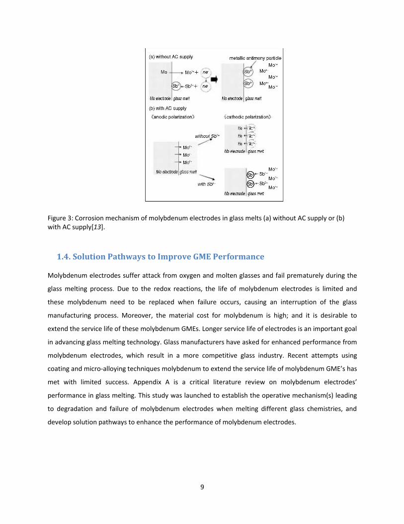
Yamamoto[13] investigated the influence of antimony, which is used as a refining agent, as well as, the
effect of temperature on the corrosion of electrodes in glass melting. A schematic drawing of the
corrosion mechanism is given in Figure 3 (a) and (b)[13]. Since the normal electrode potential of
molybdenum is much lower than that of antimony, molybdenum electrodes can be easily corroded in
the glass melt containing antimony ions. The metallic antimony particles were observed around the
electrodes after dipping in the glass melt. Antimony ions and the dissolved molybdenum ions were
detected in the molybdenum/glass interface. It was concluded that molybdenum corrosion rates were
proportional to the antimony concentration in the glass melt and the dominant factor of the corrosion
process was the redox reaction of the molybdenum electrodes with antimony ions in the glass melt.
9
Figure 3: Corrosion mechanism of molybdenum electrodes in glass melts (a) without AC supply or (b) with AC supply[13].
1.4. Solution Pathways to Improve GME Performance
Molybdenum electrodes suffer attack from oxygen and molten glasses and fail prematurely during the
glass melting process. Due to the redox reactions, the life of molybdenum electrodes is limited and
these molybdenum need to be replaced when failure occurs, causing an interruption of the glass
manufacturing process. Moreover, the material cost for molybdenum is high; and it is desirable to
extend the service life of these molybdenum GMEs. Longer service life of electrodes is an important goal
in advancing glass melting technology. Glass manufacturers have asked for enhanced performance from
molybdenum electrodes, which result in a more competitive glass industry. Recent attempts using
coating and micro-alloying techniques molybdenum to extend the service life of molybdenum GME’s has
met with limited success. Appendix A is a critical literature review on molybdenum electrodes’
performance in glass melting. This study was launched to establish the operative mechanism(s) leading
to degradation and failure of molybdenum electrodes when melting different glass chemistries, and
develop solution pathways to enhance the performance of molybdenum electrodes.

10
2. Objectives
The main objective of this study is to establish the failure mechanism for molybdenum electrodes and to
develop solutions to extend the service life of molybdenum GMEs. Although oxidation and corrosion
problems are decoupled, there may be some interactions between them, causing coupled problems in
reality. For example, oxidizing the electrode initially may have an effect on the corrosion resistance in
the glass melt. Thus it is critical to first establish the failure mechanism of molybdenum electrodes, in
order to develop solution pathways.
Three phases have been laid out to accomplish the above stated objectives:
Phase 1: Analyze used electrodes from the commercial sector; carry out post-mortem analysis of
failed electrodes and develop hypotheses for failure modes and mechanisms.
Phase 2: Design of MoSiB coating for molybdenum electrodes to improve oxidation resistance.
Phase 3: Design molybdenum electrodes to overcome the failure modes, identified in Phase 1
and 2. Beta site testing of differently processed molybdenum electrodes in different glass
chemistry environments.
Based on the methodology mentioned above, the ultimate goal is to introduce to the glass
manufacturing market a GME that is far superior to existing GMEs.

11
3. Failure Mechanisms in Molybdenum (Mo) Electrodes
3.1. Background
The function of molybdenum electrodes in glass melting furnaces is to deliver electrical current into
glass melts, providing Joule heating. The molybdenum electrode needs to be replaced when one
corrodes or breaks off during the life of the furnace. Bottom and side mounted electrodes are basic solid
molybdenum cylinders. If the electrode is side mounted, the tip of the electrode will undergo severe
corrosive attack which usually produces as a ‘pencil’ shaped electrode. As the glass melt becomes more
corrosive, the side-mounted electrodes need to be pushed in to maintain the correct current density
and melt temperature. Molybdenum electrodes are used as heaters for glass melting either via all-
electric heating or electric-boosting methods. In all-electric heating furnaces, glass melts are only heated
by molybdenum electrodes, while, electric-boosting is an add-on technique to assist the conventional
combustion system in order to improve the efficiency and to more effectively control melt temperature.
All-electric furnaces are limited by higher operating cost and shorter system lifespan (including the
service life of electrodes) than conventional furnaces.
Based on the glass industry experience, molybdenum electrodes usually last about two years in the glass
melting furnace if they were used for electric-boosting. Ideal molybdenum electrodes shall last as long
as the service life of glass melting furnaces (fourteen years depending on the conditions) to eliminate
the cost and safety issues caused by changing electrodes.
3.2. Examination Results and Discussions
3.2.1. Commercial Electrodes from Glass Industry
The failed molybdenum electrode assembly shown in Figure 4 was obtained from a commercial glass
producer. It was installed and operated in the molten glass for about one year. Figure 5 indicates the
design of the electrode assembly, which is made of a solid head and a hollow shaft from molybdenum.
Upon disassembly of the electrode, severe degradation was observed (Figure 4). Visual inspection
revealed significant metal loss from the molybdenum head, as shown by the red dashed lines in Figure 6.
Further examination of the electrode assembly revealed that the molybdenum electrode head suffered
severe corrosion attack resulting in significant loss in diameter. The minimum diameter of the electrode
head was about 2 inches (i.e., less than 50% of the original diameter). Glass deposits had adhered to the

12
surface of the electrode head. Severe pitting corrosion attack was also observed in the core of the
molybdenum head close to the shaft, as shown in Figure 7.
Figure 4: Molybdenum electrode assembly: a) electrode head, and b) electrode shaft.
Figure 5: The schematic sketch showing the electrode assembly before the failure.
a
b

13
Figure 6: Photograph showing a significant loss of the molybdenum electrode head in diameter.
Figure 7: Cross section of molybdenum electrode head: a) close to electrode shaft; b) close to tip of head.

14
Corrosion investigations were conducted on the electrode head. Two disks were sectioned from both
sides of the electrode head; one was close to the shaft and the other was close to the tip of the head
(Figure 6). For each disk, two metallurgical samples were prepared; one was for the outside surface,
which was exposed to the molten glass and the other was for the core area, which suffered pitting
attacks (Figure 8).
The first disk (close to the electrode shaft) was visually inspected after sectioning. It showed some
evidences of uniform general attack on the outside surface and some pitting corrosion attack in the
center (Figure 7 (a), 8). The outside surface was rough and uneven, had a dull appearance, and
contained some glass deposits. Further examination of the surface using a Scanning Electron Microscope
with energy-dispersive X-ray analyses (SEM/EDS) revealed glass penetration at the interface between
molybdenum and molten glass (Figure 9). Analysis of the plate center, the core and the black concentric
circle (shown in Figure 8) showed the presence of diffused glass components (Al, Si, and O). Some
penetrated glasses were also evident in the black concentric circle of the first plate (Figure 10).
Continued evaluation of the center of the plate using SEM/EDS revealed that iron was also present in
the core of the electrode head, besides the glass components (Figure 11).
The second disk (close to the tip of the electrode head) was visually inspected after being sectioned. It
shows evidence of irregular attack on the outside surface, which was more severe than on the first disk.
Besides the dull color and glass deposits, cracks were also observed on the outside surface (Figure 6).
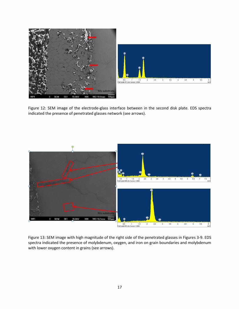
Evaluation of this surface using SEM/EDS revealed that much more glass penetration at the electrode-
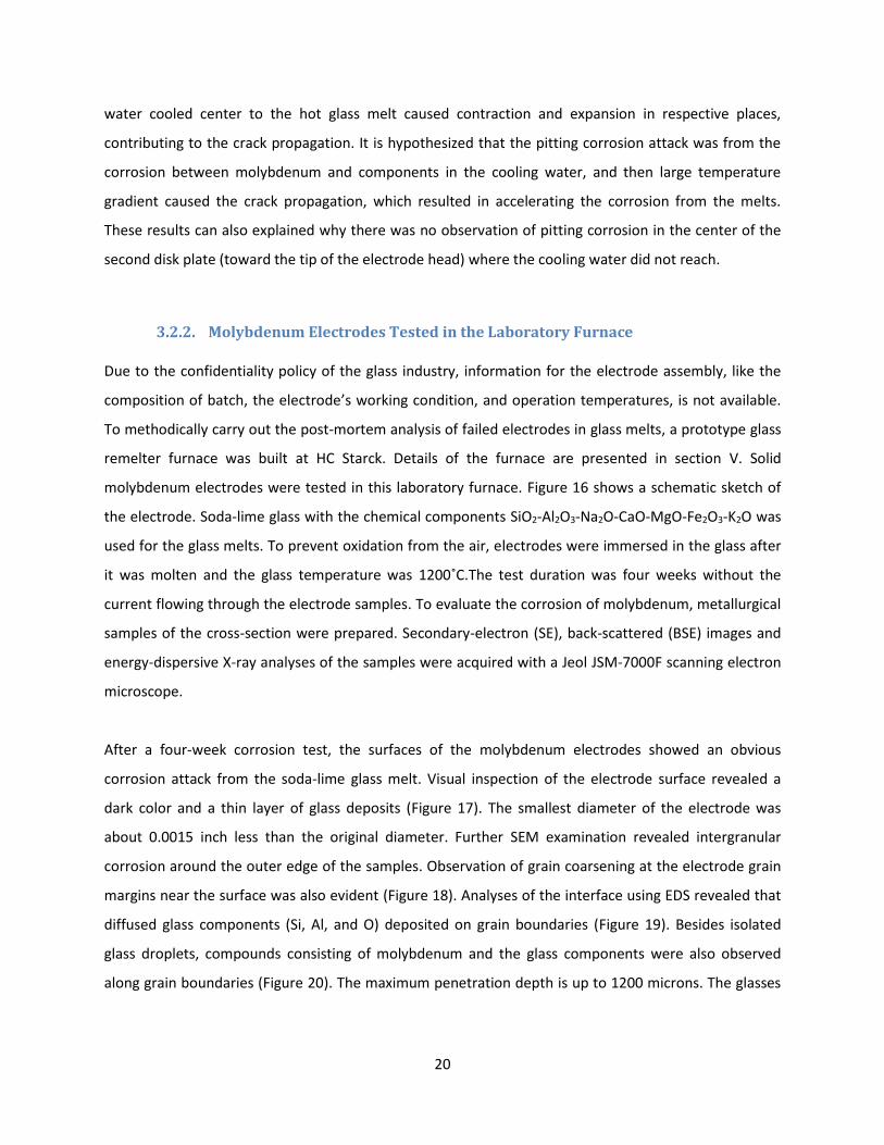
glass interface than in the first disk (Figure 12). On the right side of the penetrated glass in Figure 12,
molybdenum and oxygen were observed both in grains and on grain boundaries, while iron was only
identified on grain boundaries (Figure 13). On the left side, further examination indicated the amount of
oxygen was significantly greater on the grain boundaries than in grains and no iron was observed (Figure
14). The majority of the center of the disk plate was in good condition except for the middle black
concentric circle (Figure 7 (b)). There is no evidence of pitting or general corrosion attack on the center
of the plate. Continued analysis of the middle area of the plate identified the black concentric circle as
also diffused glass components (Figure 15).Another important observation is that molybdenum was also
identified in Figure 15. The loose molybdenum oxides, which dissolved into the glass components from
the electrode substrate showed no alloying with other glass components. Further investigation of the
electrode shaft was not performed.

15
Figure 8: Two metallurgical samples were prepared from the green circle position.
Figure 9: SEM image of the outside surface of the first disk plate. EDS spectra indicated the presence of penetrated glasses (see arrows).

16
Figure 10: SEM image of black concentric circle of the first disk plate. EDS spectra indicated the presence of diffused glass components and glass droplets (see arrows).
Figure 11: SEM image of the core of the first disk plate. EDS spectra indicated the presence of diffused glass components (see arrows).
17
Figure 12: SEM image of the electrode-glass interface between in the second disk plate. EDS spectra indicated the presence of penetrated glasses network (see arrows).
Figure 13: SEM image with high magnitude of the right side of the penetrated glasses in Figures 3-9. EDS spectra indicated the presence of molybdenum, oxygen, and iron on grain boundaries and molybdenum with lower oxygen content in grains (see arrows).

18
Figure 14: SEM image with high magnitude of the left side of the penetrated glasses in Figures 3-9. EDS spectra indicated the presence of molybdenum and oxygen in grains and on grain boundaries (see arrows).
Figure 15: SEM image of the black concentric circle of the second disk plate. EDS spectra indicated the presence of diffused glass components and loosen molybdenum oxides (see arrows).

19
Corrosion investigations on the commercial electrode assembly points out that the failure of the
electrode assembly is not only due to the glass melts, but also the design itself. The corrosivity of glass
melts greatly impact the life of molybdenum electrodes. The corrosion of pure molybdenum is a redox
reaction between metallic molybdenum and the depolarizer[12] (like Fe3+, Co2+, Ni2+, or Sb3+) in glass
melts. Metallic molybdenum is oxidized and dissolved in the glass melts while the depolarizer is reduced
to metallic iron, cobalt, nickel or antimony, which in turn can dissolve additional metallic molybdenum.
This indicates that molybdenum was loosened in the form of metallic particles by corrosion, resulting in
the glass intrusion and the surface removal of the molybdenum electrode head. The glass batch is
different from plant to plan and location to location. In some case, glass batches may contain from 35%
to 50% recycled glass. Although the exact compositions of glass melts are not available, the basic
chemical components of SiO2 and Al2O3 identified by EDS are known from the glass melts. Evaluations of
outside surface of the electrode head indicated an intergranular attack in the near-surface region of the
electrode head. The tip of the head was more heavily corroded than the rest of the electrode surface,
because the glasses had formed a continuous network. Another observation on the left side of
penetrated glasses (next to the molten glass) is that only molybdenum oxides were identified in this
area. As before, the oxygen content on the grain boundaries was much higher than in the grains. It is
hypothesized that molybdenum was initially oxidized by oxygen during the furnace startup (before the
glass melted at 1000˚C), when the air was present. Molybdenum is oxidized by air at temperature above
700˚C[14], resulting in the formation of molybdenum oxides along grain boundaries of molybdenum
electrodes. In addition, iron was only observed on the grain boundaries on the right side of penetrated
glasses (next to the electrode substrate), which indicates the redox reaction between metallic
molybdenum and Fe3+ from the melts occurred on grain boundaries. Molybdenum is corroded on the
account of the reduction of the molten iron, which defines the corrosiveness of the glass melt[12]. This
ultimately degraded the mechanical strength of the electrode. The cracks observed near the tip portion
are evidence of this degradation.
The electrode assembly which has been investigated was designed with the external water jacket.
Cooling water was pumped inside through the shaft to cool down the electrode assembly so that the
molybdenum was not susceptible to corrosion. Evaluations of the pitting corrosion attacks on inside of
the electrode head indicated the cooling water had also contributed to molybdenum corrosion. There is
often a direct contact of molybdenum with the components in the water mainly consisting of copper
and brass which can enhance the corrosion attack[15]. Moreover, large temperature gradient from the
20
water cooled center to the hot glass melt caused contraction and expansion in respective places,
contributing to the crack propagation. It is hypothesized that the pitting corrosion attack was from the
corrosion between molybdenum and components in the cooling water, and then large temperature
gradient caused the crack propagation, which resulted in accelerating the corrosion from the melts.
These results can also explained why there was no observation of pitting corrosion in the center of the
second disk plate (toward the tip of the electrode head) where the cooling water did not reach.
3.2.2. Molybdenum Electrodes Tested in the Laboratory Furnace
Due to the confidentiality policy of the glass industry, information for the electrode assembly, like the
composition of batch, the electrode’s working condition, and operation temperatures, is not available.
To methodically carry out the post-mortem analysis of failed electrodes in glass melts, a prototype glass
remelter furnace was built at HC Starck. Details of the furnace are presented in section V. Solid
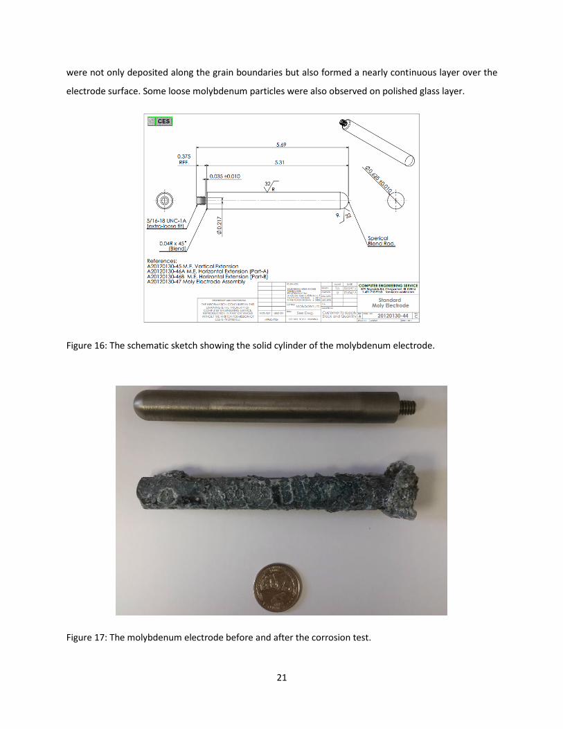
molybdenum electrodes were tested in this laboratory furnace. Figure 16 shows a schematic sketch of
the electrode. Soda-lime glass with the chemical components SiO2-Al2O3-Na2O-CaO-MgO-Fe2O3-K2O was
used for the glass melts. To prevent oxidation from the air, electrodes were immersed in the glass after
it was molten and the glass temperature was 1200˚C.The test duration was four weeks without the
current flowing through the electrode samples. To evaluate the corrosion of molybdenum, metallurgical
samples of the cross-section were prepared. Secondary-electron (SE), back-scattered (BSE) images and
energy-dispersive X-ray analyses of the samples were acquired with a Jeol JSM-7000F scanning electron
microscope.
After a four-week corrosion test, the surfaces of the molybdenum electrodes showed an obvious
corrosion attack from the soda-lime glass melt. Visual inspection of the electrode surface revealed a
dark color and a thin layer of glass deposits (Figure 17). The smallest diameter of the electrode was
about 0.0015 inch less than the original diameter. Further SEM examination revealed intergranular
corrosion around the outer edge of the samples. Observation of grain coarsening at the electrode grain
margins near the surface was also evident (Figure 18). Analyses of the interface using EDS revealed that
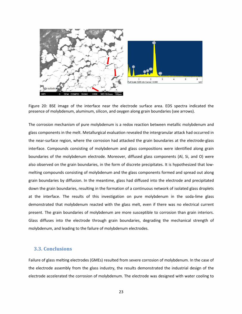
diffused glass components (Si, Al, and O) deposited on grain boundaries (Figure 19). Besides isolated
glass droplets, compounds consisting of molybdenum and the glass components were also observed
along grain boundaries (Figure 20). The maximum penetration depth is up to 1200 microns. The glasses
21
were not only deposited along the grain boundaries but also formed a nearly continuous layer over the
electrode surface. Some loose molybdenum particles were also observed on polished glass layer.
Figure 16: The schematic sketch showing the solid cylinder of the molybdenum electrode.
Figure 17: The molybdenum electrode before and after the corrosion test.

22
Figure 18: SEM image of molybdenum electrodes shows an intergranular corrosion around the outer edge.
Figure 19: SEM image of the interface near the electrode surface area. EDS spectra indicated the presence of precipitated glass components on grain boundaries (see arrows).
23
Figure 20: BSE image of the interface near the electrode surface area. EDS spectra indicated the presence of molybdenum, aluminum, silicon, and oxygen along grain boundaries (see arrows).
The corrosion mechanism of pure molybdenum is a redox reaction between metallic molybdenum and
glass components in the melt. Metallurgical evaluation revealed the intergranular attack had occurred in
the near-surface region, where the corrosion had attacked the grain boundaries at the electrode-glass
interface. Compounds consisting of molybdenum and glass compositions were identified along grain
boundaries of the molybdenum electrode. Moreover, diffused glass components (Al, Si, and O) were
also observed on the grain boundaries, in the form of discrete precipitates. It is hypothesized that low-
melting compounds consisting of molybdenum and the glass components formed and spread out along
grain boundaries by diffusion. In the meantime, glass had diffused into the electrode and precipitated
down the grain boundaries, resulting in the formation of a continuous network of isolated glass droplets
at the interface. The results of this investigation on pure molybdenum in the soda-lime glass
demonstrated that molybdenum reacted with the glass melt, even if there was no electrical current
present. The grain boundaries of molybdenum are more susceptible to corrosion than grain interiors.
Glass diffuses into the electrode through grain boundaries, degrading the mechanical strength of
molybdenum, and leading to the failure of molybdenum electrodes.
3.3. Conclusions
Failure of glass melting electrodes (GMEs) resulted from severe corrosion of molybdenum. In the case of
the electrode assembly from the glass industry, the results demonstrated the industrial design of the
electrode accelerated the corrosion of molybdenum. The electrode was designed with water cooling to
24
lower its operating temperature and reduce the corrosion rate of molybdenum. However, the copper
and brass components in contact with the cooling water enhanced the corrosion of molybdenum. In
addition, large temperature gradients within the electrode contributed to the crack propagation. These
factors resulted in accelerating the corrosion of molybdenum.
Furthermore, metallurgical evaluation also revealed two different degradation mechanisms acted on the
molybdenum electrode: the superficial oxidation and the intergranular corrosion of molybdenum.
Molybdenum, in particular, is subject to severe oxidation in air at high temperatures. In atmosphere of
oxygen, molybdenum trioxide (MoO3) is produced above 700˚C and will volatilize and sublimes fast as it
forms. Molybdenum dioxide (MoO2) is generated by the reduction of MoO3 with molybdenum(14).
Intermediate MoO2 forms along the grain boundaries at the interface layer between the molybdenum
substrate and the glass melts, which agrees the EDS results of Figure 14. The metal loss at the surface
results from the superficial oxidation of molybdenum.
The second corrosion mechanism of molybdenum, intergranular attack, is caused by the individual glass
components. The rate of this attack depends on the concentration of these components in the glass
melts even if there no electrical current is present. The corrosion of molybdenum at electrode-glass
interface was ascertained by means of SEM/EDS measurements on the electrode cross-section. The
molybdenum grain boundaries are more susceptible to corrosion than the grain interiors. SEM/EDS
images (Figure 13, Figure 18, and Figure 20) showed evidence of the intergranular corrosion starting
from the surface. Observations of grain coarsening at grain margins indicate compounds consisting of
molybdenum and glass components deposited along grain boundaries. SEM/EDS images (Figure 12 and
Figure 19) showed evidence of the precipitated glass droplets which had formed a nearly continuous
plain structure network, indicating that glasses had penetrated along the grain boundaries. The service
life of the molybdenum electrode is determined by both surface oxidation and intergranular corrosion
attack. In the case of the commercial electrode assembly, the grain boundary corrosion effect was minor.
Although intergranular corrosion played a minor role in this component’s service life, it is important
since this attack can lead to individual crystals falling out of the molybdenum electrode. This
phenomenon reduces the mechanical strength of the electrode and a greater danger of mechanical
failure than would be expected based on surface metal loss alone.

25
4. Hypothesis for the Failure of Molybdenum Electrodes Used in Melting
Glass
Since molybdenum electrodes are naturally consumed or fail prematurely during the glass melting
process, an initial hypothesis was formed to describe the potential failure mechanism. The experiments
that serve to support the theoretical assumptions can be found in part three. The initial hypothesis for
this study assumed the general failure mode was a combination of oxidation and corrosion. Thus it is
easier to identify the governing factors, variables, and the boundary conditions of each failure mode.
The general function of molybdenum electrodes in electrical heating system is to assist in heating the
glass melt through electrical resistance. Many questions are immediately raised from the above
definition: What are the limits to molybdenum electrodes? What is the effect of molten glasses on
molybdenum electrodes? How does the alternating current affect molybdenum electrodes? What is the
effect of electrodes arrangement in the glass furnace? How does the microstructure of molybdenum
electrodes change during the heating process? The present hypothesis is formulated around these
questions.
Nowadays most commercial glasses are melted on a large scale in continuous furnaces. Three basic
processes occur in the furnace tank: melting, refining, and homogenization[16]. In the case of either
electrical boosted or all-electric furnaces, electrodes are placed in the melt and a certain power is
applied. The electrical current will not run through electrodes and through the glass until the glass is
molten acts as the resistor as shown below in Figure 21.
Figure 21: The schematic sketch showing two electrodes in glass melts and electrical flow diagram.

26
The failure mode for molybdenum electrodes during the glass melting process can be broken down in
three parts to facilitate the understanding of the hypotheses. The three parts are:
Preliminary oxidation damage,
Intergranular corrosion attack,
Alternating current effect on corrosion.
In the first part, the failure mechanism involves the interaction between molybdenum and oxygen
before the glass melts. Glass usually melts at temperatures around 1000⁰C.Pure molybdenum electrodes
without a protective coating will rapidly oxidize in air at temperatures above 700⁰C. Since molybdenum
electrodes will not immersed in molten glass, which will protect the electrode from oxidation, until the
glass melt temperature is reached. Oxidation damage of the molybdenum electrode will take place
between 700⁰C and 1000⁰C before glasses become fluid[17].
The study of the oxidation resistance of molybdenum electrodes will help describe the redox reactions
between molybdenum and oxygen at elevated temperatures. In air, molybdenum is oxidized to
molybdenum trioxide (MoO3) that vaporizes from the surface above 700⁰C. Therefore degradation of
the molybdenum electrodes before the glass melts is assumed to be the formation and volatilization of
MoO3. To protect molybdenum electrodes from the oxidation attack, coating techniques were
investigated using ceramic thermal barrier coatings that resist oxidation. Since the protective coating
will be degraded over time, resulting in only temporary protection against oxidation, coated
molybdenum electrodes were exposed to air at high temperature to establish the durability of the
coating. Examinations of the coated electrodes after this test were conducted to verify the durability of
the coating to ensure the molybdenum electrode will be protected completely from the oxygen during
the startup of the furnace.
The second part of the hypothesis relates to the corrosion resistance of molybdenum to the glass melts.
Based on the preliminary results of molybdenum electrodes, the intergranular corrosion started at the
electrode-molten glass interface during the glass melting process. The dominant factor for this corrosion
mechanism involves the redox reaction between the molybdenum and molten glass. Grain boundaries,
being high energy sites, react faster than the grains. This reaction leads to preferential attack at the
grain boundaries and the loss of individual grains from the electrode surface. This ultimately results in
rapid material loss and a reduction in the mechanical strength of molybdenum electrodes due to the
27
loss of individual crystallites from molybdenum electrodes. In addition, according to the literature
review, the glass compositions have an effect on the corrosion resistance of molybdenum electrodes.
The corrosion rate of molybdenum electrodes is proportional to the depolarizers’ concentration in the
molten glass [9, 13, 18-22]. Many investigations on the relationship between the molybdenum
electrodes corrosion and different depolarizers’ precipitation rates in the glass melt with the overall
electrode current were conducted in terms of the potential of molybdenum electrodes in different
molten glasses[23]. The properties of glass are varied by adding different substances, commonly in the
form of oxides. For example, lead oxides are added brilliance and weight, arsenic and antimony oxides
are to eliminate gas bubbles formed during the melting process, and metallic oxides create the desired
colors[24]. These polyvalent ions, called depolarizers, increase the corrosivity glass melts. Molybdenum
is corroded due to the reduction of these oxides, such as lead, antimony, arsenic, or metallic oxides like
iron, nickel, and cobalt[25]. Layers of reaction products containing molybdenum, depolarizer, potassium
and small amounts of sodium were deposited on the surface of molybdenum electrodes in glass
melts[9]. Identification of these polyvalent ions and/or other elements from the melts react with
molybdenum is important in the understanding of the failure mechanism of molybdenum electrodes
used in melting glasses.
Although the oxidation and corrosion problems are decoupled, there are some interactions between
them to make it a coupled problem in this study. The corrosion tests with coated and uncoated
molybdenum electrodes were conducted to evaluate the effect of the oxidation on the corrosion
resistance of the molybdenum. The comparison corrosion rate tests were conducted in the prototype
glass remelting furnace. Different molybdenum electrode materials with the coating applied were
investigated in the tests in order to validate the hypothesis.
Lastly, the alternating current may also be a factor continually affecting molybdenum electrodes in
electrical heating process. Studies [9, 11-13, 25] indicate that the corrosion rate of molybdenum
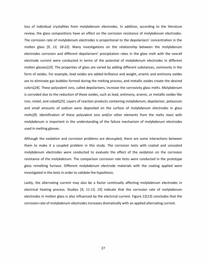
electrodes in molten glass is also influenced by the electrical current. Figure 22[13] concludes that the
corrosion rate of molybdenum electrodes increases dramatically with an applied alternating current.
28
Figure 22: Dependence of corrosion rate of molybdenum electrode on current density in the TV glass (a) without AC supple, (b) with current density of 0.53 A/cm2[13].
It has also been proven[12] that corrosion rates increase as the mean value of the anodic current
increases. The mean value of the cathodic current, which is a measure of the depolarization reactions
rate tends to be equal to the anodic current increase. And the amount of corroded molybdenum and
precipitated depolarizer are approximately equivalent within broad limits of the alternating current
loading. Additionally[11] the alternating current can affect the corrosion and depolarizer’s precipitation
rate in various glasses melts. The alternating current effect always manifests itself in parallel with a shift
of the mean electrode potential towards the more negative values and vice versa. Further examination
of the effect of alternating current on electrode corrosion was approached via comparison corrosion
tests of molybdenum electrodes with and without electrical current in the glass melt without polyvalent
ions.
The validation of these factors affecting the failure mechanism of molybdenum electrodes and
especially of the redox reactions is the critical issue to understand the failure mechanism and develop
the solution pathways to optimize GME life and mitigate failure. In this thesis, the experiments are
designed to confirm these hypotheses and answer the questions by investigating the cause and effect
relationships of molybdenum electrodes.

29
5. Approach and Experimental Procedure
The experimental sections are designed to follow the hypothesis logic and validate the hypotheses in the
previous section. The first section details tests that study oxidation resistance coatings for the
protection of molybdenum. In order to conduct the first experiment section, the ceramic barrier (MoSiB)
coating duplicated from the University of Wisconsin-Madison were scaled up and applied to protect
molybdenum electrodes. The second section following is the corrosion test with pure molybdenum
electrodes. In order to investigate the effect of the coating and alternating current on corrosion
resistance of molybdenum, both coated and uncoated molybdenum electrodes were tested in molten
glass with and without the electrical current load. Last section covers the corrosion tests with coated
glass melting electrodes. Different electrodes (molybdenum and molybdenum based alloys) were
chosen to be tested in two different kinds of glass melts separately to confirm the assumption about the
failure mechanism of electrodes in glass melts and develop the solution pathways to the optimized glass
melting electrode.
5.1. Oxidation Resistant Coating Development
Many papers [26-31] have been published detailing the oxidation behavior of the Mo-Si-B system for
several compositions and different multiphase alloys. Varying the B/Si ratio offers opportunities in
coating design to alter the oxygen diffusion pathways, the oxygen mobility, and the overall oxidation
resistance of the coating. Multiphase Mo-Si-B systems are attractive for high temperature structural
applications due to their high melting temperatures (>2000°C) and high temperature mechanical
properties[32, 33]. For Mo-rich alloys, the phase equilibria has been established as shown in Figure 23,
where the ternary intermetallic Mo5SiB2 (T2) phase is a key constituent in the multiphase equilibria[31].
There are a number of equilibrium ternary phases in Mo-Si-B system offering favorable combinations of
material properties at high temperatures because of the formation of an adherent borosilicate layer
during high temperature oxidation. For example, the three-phase alloy consisting of molybdenum (solid
solution), T2 (Mo5SiB2) and Mo3Si has excellent high temperature mechanical properties and oxidation
resistance due to the borosilicate layer generated during oxidation[34]. It is also stated in the study[35]
the multiphase comprised of mostly Mo5Si3 (T1) phase with T2 and MoB phases offers an excellent
oxidation resistance, compared to the MoSi2, owing to the existence of the borosilicate layer and
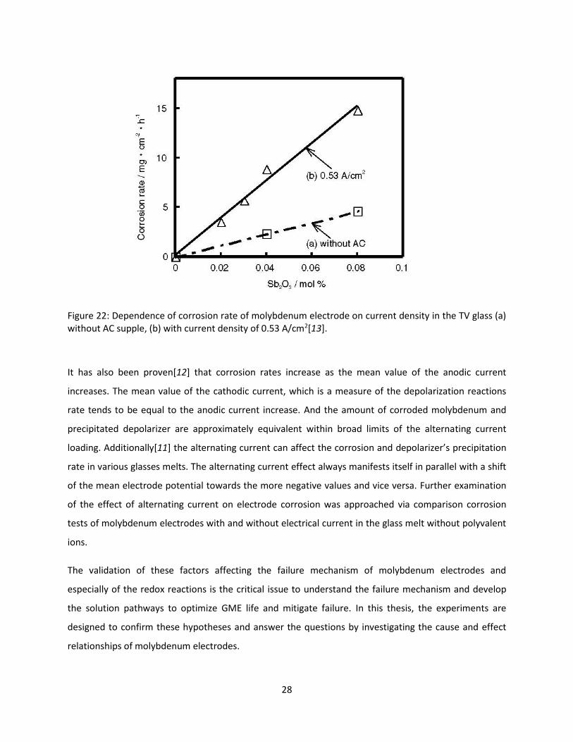
effective diffusion barrier layer (MoB). The structures of the main intermetallic phases are illustrated in
Figure 24. Since the coating processing and performance are dominated by the characteristics of internal

30
interface, the goal is to capitalize on the interdiffusion reactions to develop useful reaction products and
alloy compositions for high temperature applications.
A clear understanding of the factors controlling the equilibrium ternary phases is critical for the
oxidation protection and thermal barrier functions of the coatings. HC Starck has licensed process rights
to the oxidation resistant (MoSiB) coating[36] for molybdenum based alloys from the University of
Wisconsin-Madison (UW). In order to enhance the oxidation resistance of electrodes, a continuous
MoSiB coating was developed and adapted to molybdenum and molybdenum based alloys. The basic
strategy for the design of this coating is the creation of integrate layered structures that provide an
enhanced oxidation resistant coating for pure molybdenum and/or molybdenum based alloys in an
oxygen atmosphere at high temperatures. This is achieved using a two-step process which was carried
out to form the thermal stable, diffusion-barrier, and continuous multi-layered coating for the
protection of molybdenum. A pack cementation process as the first step was adapted for the coating
synthesis. The pack cementation, silicon (Si) and boron (B) co-deposition, is a chemical vapor deposition
(CVD) process in which the reactive vapor species are generated in situ. The second step is the high
temperature annealing (also called conditioning), which is the heat treatment that allows the
interdiffusion and reaction layer formation.
Figure 23: Mo-Si-B isothermal section at 1600˚C[32].
31
Figure 24: Crystal structures of the main intermetallic phases, namely cubic crystal structures of Mo-solid solution BCC phase and the tetragonal crystal structures of MoSi2, Mo5SiB2 (T2) and Mo5Si3 (T1) phases.
5.2. Oxidation Tests on the Coated Molybdenum
The MoSiB coating was initially applied on pure molybdenum disks. Oxidation tests on these quarter-
sized disks were conducted at 1200˚C in air for different dwell times, in order to verify the performance
of the coating against oxidation. Once a suitable coating process was established, it was scaled to coat
solid cylinder-shape electrode part. Oxidation tests on the prototype molybdenum electrode parts were
carried out at increasing temperatures. The molybdenum disks were cut from a pure molybdenum rod
(¾ inch in diameter). Each disk was sliced to a normal¼ inch thickness, polished through 800-grit SiC
paper and cleaned with ethanol in an ultrasonic cleaner. Sharp edges of disk were rounded to enhance
adhesion of the coating on the edges. The solid cylinder-shape electrode parts (0.75 inch in diameter
and 3.625 inch in length) were prepared by HC Starck’s machine shop.
The first step, pack cementation was carried out in a 2” diameter tube furnace (Figure 25).In order to
prevent oxidation damage to the molybdenum samples, the tube furnace was purged with argon during
the entire process. During pack cementation, molybdenum samples were loaded in a crucible and
uniformly surrounded by a powder mixture consisting of alumina (70 wt% Al2O3), silicon (24.3 wt% Si),
32
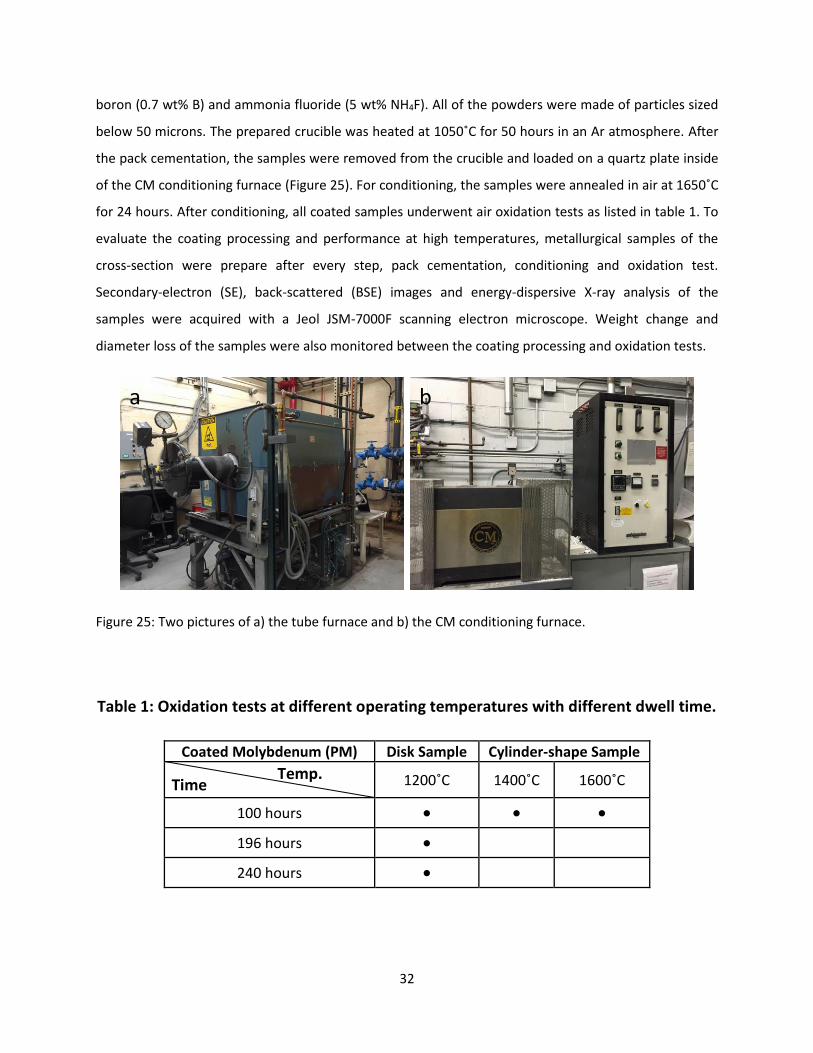
boron (0.7 wt% B) and ammonia fluoride (5 wt% NH4F). All of the powders were made of particles sized
below 50 microns. The prepared crucible was heated at 1050˚C for 50 hours in an Ar atmosphere. After
the pack cementation, the samples were removed from the crucible and loaded on a quartz plate inside
of the CM conditioning furnace (Figure 25). For conditioning, the samples were annealed in air at 1650˚C
for 24 hours. After conditioning, all coated samples underwent air oxidation tests as listed in table 1. To
evaluate the coating processing and performance at high temperatures, metallurgical samples of the
cross-section were prepare after every step, pack cementation, conditioning and oxidation test.
Secondary-electron (SE), back-scattered (BSE) images and energy-dispersive X-ray analysis of the
samples were acquired with a Jeol JSM-7000F scanning electron microscope. Weight change and
diameter loss of the samples were also monitored between the coating processing and oxidation tests.
Figure 25: Two pictures of a) the tube furnace and b) the CM conditioning furnace.
Table 1: Oxidation tests at different operating temperatures with different dwell time.
Coated Molybdenum (PM) Disk Sample Cylinder-shape Sample
Time Temp. 1200˚C 1400˚C 1600˚C
100 hours ● ● ●
196 hours ●
240 hours ●
a b

33
5.3. Comparison Corrosion Tests
5.3.1. Build-up of the remelter furnace
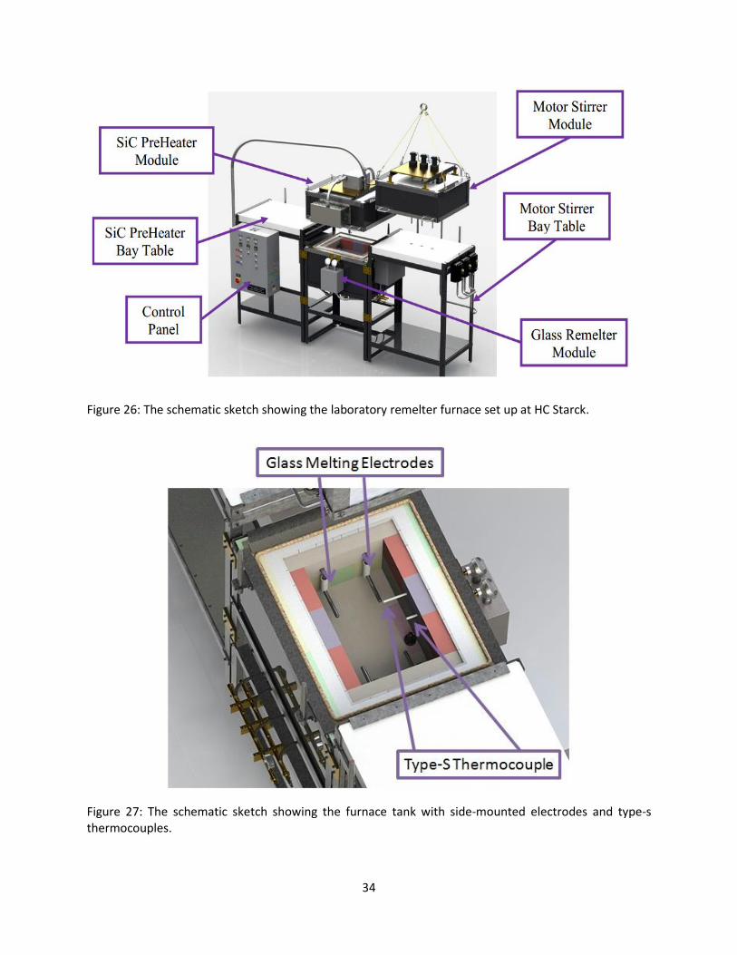
A prototype unit (remelter furnace) was designed and built by HC Starck for the molten glass corrosion
tests. The remelter furnace and furnace control system was built by Computer Engineering Service (CES).
The remelter furnace system consists of a control panel and five modular components, a silicon carbide
(SiC) heater module, a molybdenum electrode remelter module, a motor stirrer module and two bay
tables (Figure 26). The SiC heater module, working as the preheater, uses six SiC heating elements to
generate about 10,800 watts power to melt glass cullet. The remelter module, working as the melting
tank, is lined with special ceramic bricks and insulation to contain the molten glass to temperatures up
to 1575˚C. The maximum capacity of the tank is six pounds of glass cullet. A motor stirrer module is
coupled to molybdenum stirrer rods by special non-electrically conductive chucks, which operate
independently for the homogenization of the molten glass. Two bay tables are used for the purpose of
docking the SiC preheater module and the motor stirring module which are lifted by the trolley on the
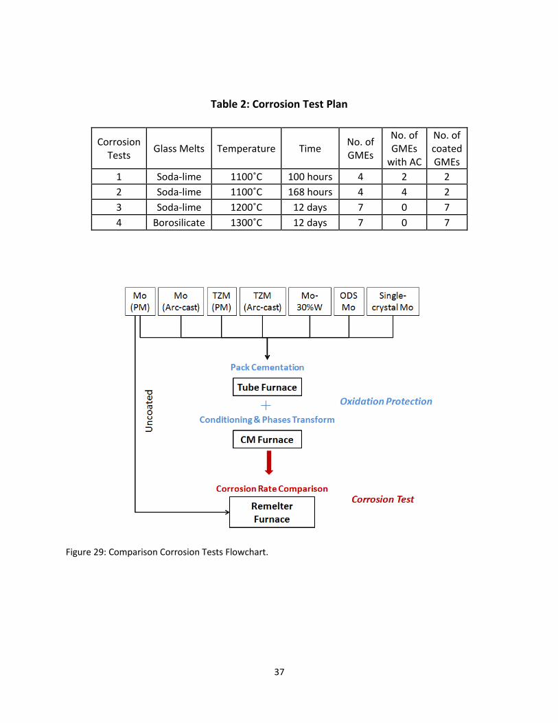
ceiling. Two type-S, sheathed, thermocouples were installed through the front wall to monitor the
operating temperature of the remelter furnace (Figure 27). Four side-mounted electrodes can be
installed into the remelter furnace, as shown in Figure 27. Figure 28 indicates how the side-mounted
electrodes electrically connect to the furnace. Water cooling is required in the pure copper (Figure 28)
to keep the electrodes from transferring excessive heat into the wiring box and damaging wiring
components. The glass cullet in this laboratory instrument is preheated by the heating elements locating
in the SiC heater module. After the glass cullet melts, electrodes can provide heat by delivering the
electricity into the molten glass. The maximum temperature the remelter furnace can reach is about
1550˚C. The startup of this furnace usually takes 24 hours to melt the soda-lime glass from the room
temperature.
34
Figure 26: The schematic sketch showing the laboratory remelter furnace set up at HC Starck.
Figure 27: The schematic sketch showing the furnace tank with side-mounted electrodes and type-s thermocouples.

35
Figure 28: The schematic sketch showing how the side-mounted electrodes electrically connect to the furnace.
5.3.2. The Choice of Glass Melts
The service life of molybdenum electrodes depends on the corrosivity of the glass, which is dependent
on the glass compositions, which vary enormously. Most common glass compositions are based on SiO2
as the glass former. Two glass compositions that have largest market share of glass industry in US were
chosen for the corrosion tests in this study, soda-lime glass and borosilicate glass. Soda-lime glass is
referred to as “easy glass”, which is inexpensive and has low-melting temperature. The chosen soda-
lime glass has the basic composition of SiO2-Al2O3-Na2O-K2O-MgO-CaO-Fe2O3. In glass industry,
molybdenum electrodes are mostly side mounted in the soda-lime glass melts, standing horizontal to
side walls of furnace. Borosilicate glass (“hard glass”) with higher melting point is mechanically stronger
and harder than soda lime glass. The chosen borosilicate glass has the basic composition of SiO2-Al2O3-
Na2O-B2O3-MgO-CaO, which has higher B2O3 content than does the soda-lime glass. Molybdenum
electrodes serving for the borosilicate glass are usually larger and given higher current intensity than for
soda lime glass because of the higher corrosivity of the borosilicate glass. In glass industry, electrodes
applied in borosilicate glasses are usually installed vertically on the bottom of furnace (bottom
mounted).

36
5.3.3. Corrosion Tests on Glass Melting Electrodes
In order to evaluate the corrosion resistance of glass melting electrodes in glass melts, four corrosion
tests were performed in different glass melts with different electrodes, as listed in table 2. In the first
corrosion test, only pure molybdenum was examined under laboratory conditions in the soda-lime glass
melt to investigate the effect of alternating current and the MoSiB coating on pure molybdenum in the
molten glass. The first test was approached in a four-electrode arrangement at 1100˚C for 100 hours.
Four molybdenum electrodes were placed in the melting tank together with the glass cullet at room
temperature, two diagonal electrodes were electrical connected (one was coated while the other was
uncoated) and other two electrodes were not electrical connected (again, one was coated while the
other was uncoated). Two connected electrodes began to deliver the electricity into the glass as soon as
the glass cullet melted. The current density in the range of 0-1.5 A/cm2 was applied on two electrodes.
The second corrosion test was also investigated on pure molybdenum electrodes only in the soda-lime
glass melts at 1100˚C. In order to verify whether the alternating current only accelerate the corrosion
rate of molybdenum (do not change the corrosion mechanism of molybdenum), four molybdenum
electrodes were all electrically loaded in the tank (two of them were coated and the other two were
uncoated). Electrodes started to provide heat when the glass cullet melted. The current density in the
range of 0-1.5 A/cm2 was also applied on four electrodes. The duration of the second experiment was
168 hours. In the third and fourth corrosion tests, the behavior of seven electrodes (such as powder
metallurgical processed (PM) Mo, arc-cast Mo, powder metallurgical processed (PM) TZM, arc-cast TZM,
oxide dispersion strengthened (ODS) Mo, Mo-30%W, and single crystal Mo) were investigated in two
kinds of glass compositions, soda-lime and borosilicate glass melts, without the electrical current . Seven
electrodes were all machined as the solid cylinder-shape (0.625 inch in diameter and 5.31 inch in length)
shown in Figure 16. In order to study the performance of the coating in different glass melts, seven
electrodes were all coated first and then placed into the melting tank after the glass melted to avoid the
oxidation attack occurred during the startup of the remelter furnace. The flowchart of the comparison
corrosion tests is shown in Figure 29. These two tests without electric current were carried out at
1200˚C in soda-lime glass, and at 1300˚C in borosilicate glass. The duration of the experiments was
twelve days. Table 3 lists all different electrodes in different corrosion conditions involved in four
corrosion tests. To investigate the corrosion of molybdenum and the molybdenum alloy in experiments,
diameter loss was first measured after test. Further study with optical microscopy and SEM, slices were
cut and then polished. Secondary-electron (SE), back-scattered (BSE) images and energy-dispersive X-ray
analysis of the samples were acquired with a JEOL JSM-7000F scanning electron microscope.
37
Table 2: Corrosion Test Plan
Corrosion Tests
Glass Melts Temperature Time No. of GMEs
No. of GMEs
with AC
No. of coated GMEs
1 Soda-lime 1100˚C 100 hours 4 2 2
2 Soda-lime 1100˚C 168 hours 4 4 2
3 Soda-lime 1200˚C 12 days 7 0 7
4 Borosilicate 1300˚C 12 days 7 0 7
Figure 29: Comparison Corrosion Tests Flowchart.

38
Table 3: Glass Melting Electrodes Tested in Corrosion Tests
GMEs
Surface Condition Current Load Glass Composition
Coated Uncoated Without
AC With AC Soda-lime Borosilicate
Mo (PM) ● ● ● ● ● ●
Mo (Arc-cast) ●
●
● ●
TZM (PM) ●
●
● ●
TZM (Arc-cast) ●
●
● ●
Mo-W alloy ●
●
● ●
ODS-Mo ●
●
● ●
Single-crystal Mo ●
●
● ●

39
6. Results
6.1. Oxidation Behavior of Coated Molybdenum
6.1.1. Oxidation Resistant Mo-Si-B-Based Coating
Since multi-phase alloys in the Mo-Si-B system are attractive due to their high melting points, high
temperature mechanical properties and great oxidation resistance, an integrated coating design has
been developed to protect molybdenum and molybdenum based alloys from high temperature
oxidation. This was accomplished through the formation of a multi-layered structure which consists of
oxygen diffusion, oxidation resistant, and diffusion barrier layers. For the development of the coating
design, the first step is to locate the key composition and kinetic factors influencing the oxidation
response. This has been accomplished by analyzing the oxidation products and the reaction pathway as
a basis for applying a kinetic biasing strategy to control the coating phase structure and sequencing and
enhance the oxidation resistance[37]. This approach for refractory metals was tested for Mo-Si-B alloys
where the key components of the coating design are identified and then extended to other
molybdenum and molybdenum based alloys.
Many studies have investigated the oxidation behavior of Mo-Si-B alloys. There are two distinct stages
during the oxidation of Mo-Si-B alloys at high temperatures. First, during initial contact with oxygen at
elevated temperatures, Mo-Si-B alloys experience a transient oxidation stage with a high recession rate
that corresponds to rapid mass loss due to the evaporation of molybdenum trioxide (MoO3)[14], which
does not offer any protection to continued oxidation. The second stage, the steady state, leads to the
formation of a protective SiO2 phase (which also contains B2O3) that initiated during the transient period
and turns into a continuous layer to protect the alloy from further rapid oxidation. The oxidation rate is
limited by oxygen diffusion through the borosilicate layer. Yoshimi et al.[30] used thermogravimetric
analysis to test the Mo-Si-B alloy at several different temperatures from 973 K to 1673 K for up to 24
hours. As shown in Figure 30, at low temperatures, the alloy initially gained weight, and then began to
lose weight because MoO3 started to volatilize. The alloy lost weight continuously at higher
temperatures because molybdenum was being oxidized during the oxidation of silicon and boron.
Weight loss was quite obvious at 1673 K, which was about three times faster than the rate of weight loss
at 1573 K. This indicates the passive layer (SiO2-B2O3) was protective at some point, but it did not
completely reduce the partial pressure of oxygen to protect molybdenum from the oxidation.

40
Figure 30: Weight change as a function of time and temperature for Mo-12.5Si-25B using thermogravimetric analysis[30].
From the previous studies [14, 33, 37], the oxidation behavior of Mo-Si-B alloys starts with the initial
transient stage which is accompanied by weight loss because of the volatilization of MoO3 as well as
boron oxides. The oxidation process then reaches steady state with the formation of a borosilicate layer
at the outermost area of the oxide structure. The oxidation continues in air with the SiO2 (+B2O3) layer
providing, protection from oxidation, but not completely blocking oxygen diffusion. With continued
exposure in air, the thickness of the oxide structure increases along with a recession of the base alloy.
The initial temperature for the steady state oxidation depends on the composition of the Mo-Si-B
substrate alloys. It is clarified[34] that the B/Si ratio controls composition of the passive layer (SiO2-B2O3)
that forms upon oxidation. It is generally understood that increasing the silicon content improves
oxidation resistance due to the more passive SiO2 rich layer, which has been generated. However,
excessive silicon will degrade low temperature oxidation resistance, because MoO3 forms and vaporizes
more quickly than the protective SiO2 layer forms. Furthermore, the B/Si ratio controls the nature of the
transient stage[28]. In order to improve the oxidation performance of the Mo-Si-B alloys, it is necessary
to minimize the transient stage. In addition, the high volatility of B2O3 will also impact the oxidation
resistance at high temperature[28]. Therefore, the composition variation of the SiO2-B2O3 passive layer
affects the viscosity, melting temperature and oxygen diffusivity [38]. The significance of the B/Si ratio
opens up opportunities in coating design to alter the oxygen diffusion pathways, the oxygen mobility

41
and the overall oxidation resistance of the coating. A kinetic biasing strategy has been developed to
capitalize on the reactions between different phases to develop useful reaction products and alloy
compositions that evolve toward a steady state of a compatible system[34].
6.1.1.1. Silicon Pack Cementation
Perepezko[37] applied the pack cementation process to control the B/Si ratio for the synthesis of the
oxidation resistant silicide coating on Mo-Si-B alloys. In the silicon pack cementation process, silicon
fluoride (SiF4) vapor synthesized from the reaction between Na4F and silicon powders at elevated
temperature reacts with the substrate to enrich the surface with Si[39]. During the silicon-pack
cementation process, a steep chemical potential gradient of Si across the vapor/substrate interface
produces a flux of Si into the substrate that uniformly enriches the local Si concentration and results in
the synthesis of a molybdenum disilicide (MoSi2) coating layer[39-41]. A back scattered SEM image of
the cross section of an as-Si packed sample is shown in Figure 31. Underneath the MoSi2 layer, there is a
Mo-rich silicide layer of Mo5Si3 (T1 phase) and dispersoids of the MoB phase[34].
Figure 31: Back scattered SEM image of the silicide coatings onto Mo-3Si-1B (wt%) composed of MoSi2 and the B-doped Mo5Si3 (T1 phase) with dispersoids of MoB particles underneath[34].
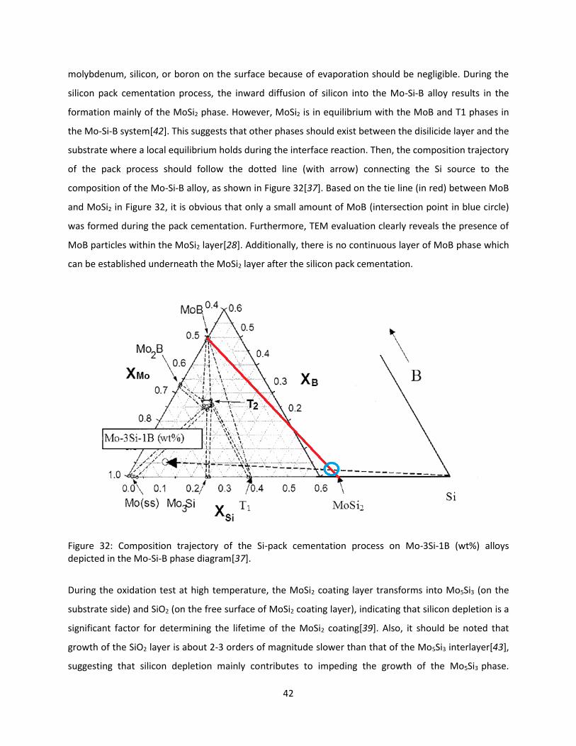
The presence of MoB phase can be understood from the diagram of composition trajectories of the Si-
pack cementation process into this alloy as shown in Figure 32[37]. In this study, since the operating
temperature for the pack cementation process was relatively low (900˚C), any weight loss of
42
molybdenum, silicon, or boron on the surface because of evaporation should be negligible. During the
silicon pack cementation process, the inward diffusion of silicon into the Mo-Si-B alloy results in the
formation mainly of the MoSi2 phase. However, MoSi2 is in equilibrium with the MoB and T1 phases in
the Mo-Si-B system[42]. This suggests that other phases should exist between the disilicide layer and the
substrate where a local equilibrium holds during the interface reaction. Then, the composition trajectory
of the pack process should follow the dotted line (with arrow) connecting the Si source to the
composition of the Mo-Si-B alloy, as shown in Figure 32[37]. Based on the tie line (in red) between MoB
and MoSi2 in Figure 32, it is obvious that only a small amount of MoB (intersection point in blue circle)
was formed during the pack cementation. Furthermore, TEM evaluation clearly reveals the presence of
MoB particles within the MoSi2 layer[28]. Additionally, there is no continuous layer of MoB phase which
can be established underneath the MoSi2 layer after the silicon pack cementation.
Figure 32: Composition trajectory of the Si-pack cementation process on Mo-3Si-1B (wt%) alloys depicted in the Mo-Si-B phase diagram[37].
During the oxidation test at high temperature, the MoSi2 coating layer transforms into Mo5Si3 (on the
substrate side) and SiO2 (on the free surface of MoSi2 coating layer), indicating that silicon depletion is a
significant factor for determining the lifetime of the MoSi2 coating[39]. Also, it should be noted that
growth of the SiO2 layer is about 2-3 orders of magnitude slower than that of the Mo5Si3 interlayer[43],
suggesting that silicon depletion mainly contributes to impeding the growth of the Mo5Si3 phase.

43
Although the growth of the T1 phase may still be rapid upon high temperature exposure, it is an
excellent protective coating provided that the T1 phase is saturated with B during the high temperature
oxidation exposure[36].
As shown in the Figure 33[28], short-term oxidation tests performed at 1400˚C illustrate the benefits of
the coating on the Mo-3Si-1B (wt%) alloy after the Si pack cementation. In the case of uncoated Mo-3Si-
1B (wt%) alloys shown in Figure 33 (a, b), the thickness reduction of the originally cube samples
indicated the large mass loss due to oxidation. Even though there was a thick and continuous
borosilicate layer observed on the surface shown in the BSE image of the cross-section, the volatilization
of B2O3 at this temperature also resulted in a large mass loss during the exposure. In contrast, the
coated samples in Figure 33 (c-d) show essentially no thickness change (no mass loss) and very limited
growth of the borosilicate layer on top of the coating (less than 15 μm after 30 h exposure)[28].
Figure 33: (a) SEM image of uncoated Mo-Si-B sample after an oxidation test at 1400˚C for 10 hours showing the extensive recession rate even though a continuous borosilicate layer develop on the surface as shown in BSE image in (b). In contrast, with the same oxidation condition, the coated sample in (c) exhibits a minimal mass loss due to the borosilicate coating protection. (d) BSE image of the coating showing the development of B-saturated T1 and the diffusion barrier underneath comprised of the T2 and boride phases[28].

44
6.1.1.2. Silicon/Boron co-Pack Cementation
However, the as pack cemented silicon layer does not provide the amount of boron which is needed to
stabilize the borosilicide and/or boride phase layer that functions as the diffusion barrier because there
is no continuous layer of MoB phase underneath the disilicide layer coating onto the Mo-3Si-1B (wt%)
alloy in Figure 31. Therefore, in the case of commercially pure molybdenum or molybdenum based
alloys (such as TZM) which does not have any B or Si contents, the co-deposition of B and Si is necessary
in order to form a continuous layer of MoB phase. As shown in Figure 34, the nominal composition path
for the co-deposition processes can be represented by rotation about the substrate nominal
composition whereby the initial vapor source moves from the pure Si to a mixed Si/B source[34].
Figure 34: Composition trajectory of Si+B pack cementation process on pure molybdenum depicted in the Mo-Si-B phase diagram.
In this thesis, the Si/B co-pack cementation process with a 35-1 weight ratio of Si to B powder sources
was adapted onto the pure molybdenum sample. Ammonium fluoride (NH4F) was chosen as the
activator instead of sodium fluoride (NaF) to react with the silicon powder in the pack mixture. Unlike
the sodium gas produced by NaF, the ammonia comes off as a gas at a much lower temperature and can
escape the crucible without reacting with molybdenum disilicide layer or forming sodium aluminate.
Figure 35 shows the molybdenum disks (0.75 inches in diameter with thickness of 0.25 inches) were
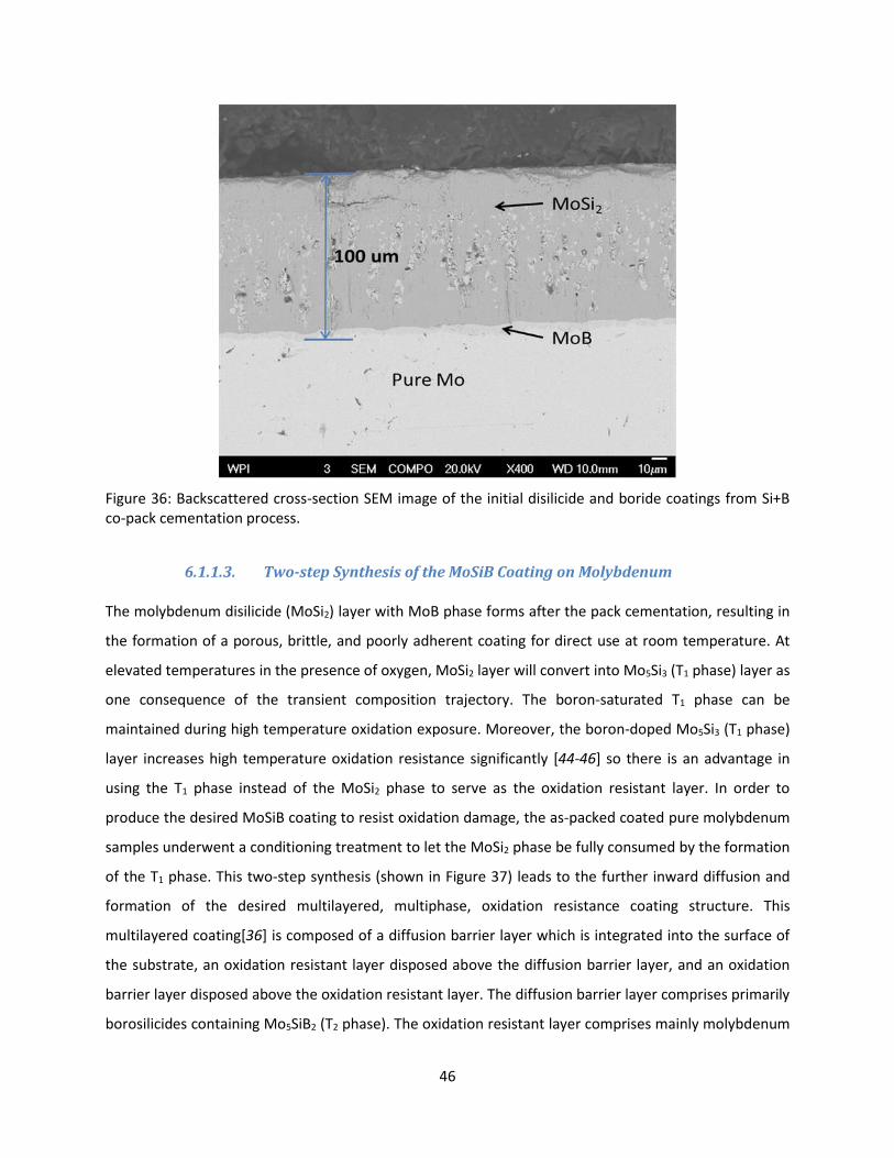
initially coated by a grey Mo-Si-B coating on the surface. Figure 36 is the back-scattered SEM image of

45
the as-packed sample, indicating that a uniform 100 μm thick layer was formed on the surface of pure
molybdenum after 50 hours at 1050˚C. During the co-pack cementation, inward diffusion to the pure
molybdenum uniformly enriches the local Si and B concentration and results in the formation of the
MoSi2 (mainly) and MoB phases. Confirmed by EDS, the continuous MoSi2 layer was observed to be
about 90 µm thick. Based on Perepezko’s work[28], the MoB phase forms both as dispersoids in the
MoSi2 layer as well as a continuous layer underneath the disilicide layer, which was observed to be
about 10 µm thick. The presence of MoB phase can be understood from the diagram of composition
trajectories of the pack cementation process into the pure molybdenum as shown in Figure 34.
Figure 35: Pure molybdenum disks after the co-pack cementation process (1050˚C/50h).
46
Figure 36: Backscattered cross-section SEM image of the initial disilicide and boride coatings from Si+B co-pack cementation process.
6.1.1.3. Two-step Synthesis of the MoSiB Coating on Molybdenum
The molybdenum disilicide (MoSi2) layer with MoB phase forms after the pack cementation, resulting in
the formation of a porous, brittle, and poorly adherent coating for direct use at room temperature. At
elevated temperatures in the presence of oxygen, MoSi2 layer will convert into Mo5Si3 (T1 phase) layer as
one consequence of the transient composition trajectory. The boron-saturated T1 phase can be
maintained during high temperature oxidation exposure. Moreover, the boron-doped Mo5Si3 (T1 phase)
layer increases high temperature oxidation resistance significantly [44-46] so there is an advantage in
using the T1 phase instead of the MoSi2 phase to serve as the oxidation resistant layer. In order to
produce the desired MoSiB coating to resist oxidation damage, the as-packed coated pure molybdenum
samples underwent a conditioning treatment to let the MoSi2 phase be fully consumed by the formation
of the T1 phase. This two-step synthesis (shown in Figure 37) leads to the further inward diffusion and
formation of the desired multilayered, multiphase, oxidation resistance coating structure. This
multilayered coating[36] is composed of a diffusion barrier layer which is integrated into the surface of
the substrate, an oxidation resistant layer disposed above the diffusion barrier layer, and an oxidation
barrier layer disposed above the oxidation resistant layer. The diffusion barrier layer comprises primarily
borosilicides containing Mo5SiB2 (T2 phase). The oxidation resistant layer comprises mainly molybdenum

47
silicides containing Mo5Si3 (T1 phase). The oxidation barrier layer comprises borosilicates (basically SiO2
with B2O3).
Figure 37: Two steps synthesis of the MoSiB coating.
During the conditioning treatment (annealing process), the inward flux of Si and B in the MoSi2 layer
leads to several conversions. The reaction: MoSi2 + 7/5 O2→ 1/5 Mo5Si3(s) + 7/5 SiO2(s) is the dominant
reaction as observed in oxidation experiments[47], with the initial MoSi2 outer layer partially converting
into both SiO2 layer and T1 phase. Outer layer of MoSi2 phase transforms into borosilicates on the
outmost surface to make up the oxidation barrier layer. It is also noted that growth of the SiO2 layer is
slower than that of the T1 phase. The newly converted molybdenum silicide (T1 phase) along with any
remaining MoSi2 is still considered to be part of the oxidation resistant layer of the coating. With
continued oxidation at high temperature, after the complete transformation from MoSi2 to T1 phase, a
portion of the T1 phase is consumed by the development of borosilicides (T2 phase) layer and dispersed
boride phase layer (MoB). The results of the work by Ito[48-50] suggest that diffusion of silicon can be
blocked by the borosilicide and/or boride phases and is in agreement with the fact[51] that mobility of
silicon in T2 phase is apparently very low and the solubility of silicon in the MoB phase is also very low.
So the T2 and MoB phase layer can serve as the effective diffusion barrier of Si from the outer silicide T1
phase into the substrate. The amounts of the T2 and MoB phases underneath the T1 phase layer depend
on the Si/B ratio of the powder mixture which can be also tracked in the composition trajectories in
Figure 34. By adjusting the annealing temperatures and times, the thickness and composition in some
layers can be carefully controlled. The two-step synthesis results in a multilayered structure where each
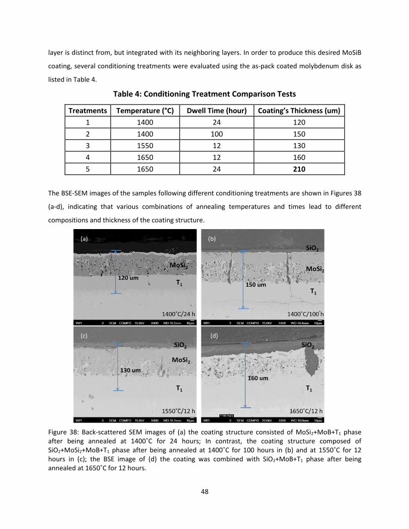
48
layer is distinct from, but integrated with its neighboring layers. In order to produce this desired MoSiB
coating, several conditioning treatments were evaluated using the as-pack coated molybdenum disk as
listed in Table 4.
Table 4: Conditioning Treatment Comparison Tests
Treatments Temperature (°C) Dwell Time (hour) Coating’s Thickness (um)
1 1400 24 120
2 1400 100 150
3 1550 12 130
4 1650 12 160
5 1650 24 210
The BSE-SEM images of the samples following different conditioning treatments are shown in Figures 38
(a-d), indicating that various combinations of annealing temperatures and times lead to different
compositions and thickness of the coating structure.
Figure 38: Back-scattered SEM images of (a) the coating structure consisted of MoSi2+MoB+T1 phase after being annealed at 1400˚C for 24 hours; In contrast, the coating structure composed of SiO2+MoSi2+MoB+T1 phase after being annealed at 1400˚C for 100 hours in (b) and at 1550˚C for 12 hours in (c); the BSE image of (d) the coating was combined with SiO2+MoB+T1 phase after being annealed at 1650˚C for 12 hours.

49
As shown in Figures 38 (a-c), the remaining MoSi2 phase indicates that MoSi2 did not fully convert to the
T1 phase. Even though the coating thickness increased, as shown in the BSE images (b) and (c), with a
longer time and higher temperature conditioning treatment, the T1 phase with remaining MoSi2 phase is
not the desirable oxidation resistant layer for the MoSiB coating. In contrast, the coating structure in
Figure 38 (d) shows complete phase conversion from MoSi2 to Mo5Si3 (T1 phase) with a 160 μm coating
thickness. The MoSi2 phase did not completely transform into the T1 phase until the annealing
temperature was increased to 1650˚C. Compared to the MoSi2 phase, the T1 phase appears to remain
stable and retains excellent oxidation resistance at higher temperatures. Furthermore, upon
conditioning of the MoSiB coating, the T1 phase is the main source to develop the T2 diffusion barrier
layer phase. So the proper annealing temperature to synthesis the desired MoSiB coating is 1650˚C. The
lifetime of this coating can be significantly influenced by the thickness of each layer because the coating
would eventually be consumed by the transformation into molybdenum with continued oxidation
exposure at elevated temperature. It can be observed in Figure 38 the converted T1+MoB phase layer is
actually thicker than the combination of the MoSi2+MoB phase layer during the conditioning treatment.
The thickness of T1+MoB phase grows with longer oxidation time because of the formation of T1+T2
phase. Moreover, the thickness of the borosilicate layer also increases with oxidation time. Since, the
growth of the coating’s thickness enables the lifetime of the coating to be increased based on the
completion of the conversion process, 24-hour oxidation exposure time at 1650˚C is chosen as the best
heat condition for the conditioning treatment, which is also listed in Table 4.
Figure 39 shows the as-coated molybdenum samples after being annealed at 1650˚C for 24 hours and
the broken quartz plate. After the conditioning treatment, the molybdenum disks were completely
covered by silica-base glasses.

50
Figure 39: As-packed molybdenum disks after the conditioning process (1650˚C/24h) in air.
Figure 40 shows a back-scattered image of a cross-section from the oxidized coated pure molybdenum
sample, demonstrating a multilayered coating structure with 210 μm thickness. The thickness of the
MoSiB coating was doubled after being annealed compared with the thickness after the co-pack
cementation. It can be discerned in the cross-section image that the MoSiB coating consisted of three
separate layer structures between the red dotted lines in Figure 40. In order to confirm the composition
of the coating structure, identified by EDS, the Si concentration depth profile of the whole coating
structure is shown in Figure 41. Based on the silicon concentration on each layer (at %), the first layer on
the top is the borosilicate layer (SiO2) formed on the outermost layer of the coating structure which
functions as the oxidation barrier layer. Underneath the borosilicate layer, T1 phase combined with T2
phase (the second layer) serves as the oxidation resistant layer. Lastly, the T2 phase with MoB phase
layer developed below the T1+T2 phase as the diffusion barrier layer. Any damage to the outer T1 phase
can be recovered from the underlying T2+MoB layer, allowing for the continued existence of the T1 layer
and a self-healing characteristic of the MoSiB coating[52].

51
Figure 40: Backscattered cross-section SEM image of the coated pure molybdenum sample which was annealed at 1650˚C for 24 hours. The coating’s thickness was increased up to 210 μm.
Figure 41: Backscattered cross section SEM image of the sample after the conditioning process compared with Si concentration depth profile of the coating structure. The elemental composition of each layer structure was identified by EDS.

52
In addition to the formation of the expected phases in the MoSiB coating structure, this multilayered
coating is integrated into the pure molybdenum substrate. Since the T1 and T2 phases blend smoothly
into each other, these layers form a continuous compositional gradient. The T1 phase is always in touch
with the MoB or T2 phase, which guarantees that T1 phase is saturated with boron. The excellent
oxidation resistance of the boron-saturated T1 phase blocks the oxygen transport and exploits the
underlying diffusion barrier (T2 and MoB phases) to obstruct the diffusion of silicon and protect pure
molybdenum from oxidation at much higher temperatures. The weight change was measured and
illustrated in Figure 42, as average 0.24 g weight gained by each molybdenum sample after being coated.
The increase of the coating volume agrees to the effect of the coating’s thickness growth to extend the
lifetime of this MoSiB coating.
Figure 42: Weight change during the two-step synthesis of the coating on pure molybdenum disk, indicating the sample gained average 0.2416 g after being coated.
6.1.2. Oxidation Behavior of Coated Pure Molybdenum Samples
Since the MoSiB coating is used to protect molybdenum electrodes from oxidation attack, the oxidation
behavior and lifetime of the coating needs to be verified by continued oxidation tests. Figure 43 shows
the exterior appearance of coated molybdenum samples after being exposed in air at 1200˚C for the
time range from 100 to 240 hours.

53
Figure 43: Pure molybdenum disks after being oxidized in air at 1200˚C for 100h, 196h, and 240h.
No visible damage to the substrate was observed on these samples, even though the surface appears
flecky, and assumed to be silica covering the sample after oxidation. There was also no diameter change
or thickness loss found on these samples after oxidation. The BSE-SEM images of the coated samples
that were oxidized for different dwell times are illustrated in Figures 44 (b-d). After being compared to
Figure 44 (a), it is clear the coating thickness decreased with oxidation time, indicating that the MoSiB
coating was consumed during the oxidation test. However, the coating still retained half of its original
thickness after being oxidized at 1200˚C for 240 hours, which is shown in Figure 44 (d). From the EDS
results on the sample oxidized for 240 hours, the existence of Mo, Si, and O is clearly indicated at the
interface. Several separate phases can be observed in the area of the coating structure: the exterior
borosilicate layer formed at the outer face which was smooth and continuous; the MoO2 phase was
identified underneath the SiO2 layer; and the T1+T2+MoB layer which is the oxidation resistant and
diffusion barrier layer of the MoSiB coating (shown in Figure 45).
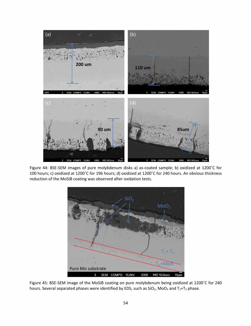
54
Figure 44: BSE-SEM images of pure molybdenum disks a) as-coated sample; b) oxidized at 1200˚C for 100 hours; c) oxidized at 1200˚C for 196 hours; d) oxidized at 1200˚C for 240 hours. An obvious thickness reduction of the MoSiB coating was observed after oxidation tests.
Figure 45: BSE-SEM image of the MoSiB coating on pure molybdenum being oxidized at 1200˚C for 240 hours. Several separated phases were identified by EDS, such as SiO2, MoO2 and T1+T2 phase.

55
The presence of MoO2 rather than MoO3 confirms that the SiO2 layer functioning as the oxidation barrier
restricts oxygen diffusion and reduces the oxygen activity. Furthermore, the T1+T2 phase serving as the
oxidation resistant layer offers excellent oxidation resistance to fully block oxygen transport so that no
molybdenum oxides were formed beyond the MoSiB coating structure or in the molybdenum substrate,
while MoO2 only synthesized underneath the SiO2 layer. In addition, Si-rich oxide precipitates were also
detected in the cracks in the coating region, but not in the pure molybdenum substrate. The MoSiB
coating is not a crack-free coating and the cracks formed during the conditioning treatment because the
MoSi2 phase is not ductile and cannot deform during the phase transformation. However, the cracks will
be filled with the SiO2 (with B2O3), which is stable and protective and will also reduce oxygen transport.
The weight change was arrested after oxidation tests and shown in Figure 46. No significant increase in
weight loss was observed among these oxidation tests. The sample lost 0.0384 g after being oxidized for
240 hours, indicating that the MoSiB coating clearly offers an enabling coating technology to pure
molybdenum for enhanced oxidation resistance at 1200˚C.
Figure 46: Weight change after the as-coated samples being oxidized, indicating that the sample lost 0.0384 g after being oxidized at 1200˚C for 240 hours.

56
6.1.3. The scale-up of the MoSiB Coating for Glass Melting Electrode (GME)
During the startup of the glass melting furnace and before the glass is molten, glass melting electrodes
(GMEs) are exposed to oxygen at elevated temperatures. This is the time when an uncoated GME would
oxidize and potentially fail prematurely due to the volatility of molybdenum trioxide. Therefore the
MoSiB coating is used as the protective coating for electrodes during startup. Initial scale up effort of the
coating on the pure molybdenum from the disk (0.75 inch diameter and 0.75 thick) to the rod (0.75 inch
diameter and 3.625 inch long) was achieved by two-step process. The molybdenum rod was coated
successfully with the glassy appearance of the MoSiB coating as shown in Figure 47. The coated samples
were tested in the following oxidation tests at 1400˚C and 1600˚C both for 100 hours. The results are
also presented in Figure 47, indicating that the coating survived after the oxidation test at 1400˚C with
no damage observed on the surface of the coating or to the substrate. While, the yellow stains (proof of
molybdenum trioxide) on the surface presents the coating failed at the corner of the part after being
oxidized at 1600˚C (shown in red circles in Figure 47). Without the protective coating, the formation of
molybdenum trioxide at the corner leaded to the mass loss of the molybdenum rod. However, after
being oxidized at 1600˚C, the coating on the rest of the surface (except for the corner section) was still
present, compared to the rod being oxidized at 1400˚C.
Figure 47: The pictures of (a) as-coated molybdenum electrode, the coated sample with continued oxidation test in (b) at 1400˚C for 100 hours, and in (c) at 1600˚C for 100 hours with yellow stains on the surface. The coating survived the oxidation test at 1400˚C for 100 hours, while the coating failed starting at the corner after being oxidized at 1600˚C for 100 hours.

57
Samples were cut from the middle of the electrode to examine the residual coating structure. As
illustrated in Figures 48 (a) and (b), the presence of the SiO2 layer and the MoO2 phase indicates the
growth of the silica layer on the surface during oxidation. Further, as shown in the red circle in Figure 48
(b), a thin SiO2 layer was observed between the coating and the substrate suggesting that silicon oxide
had started to diffuse through the MoSiB coating after 100-hour oxidation at 1600˚C. The residual
thickness of the coating after 100-hour oxidation test is presented in Figure 49. The coating’s thickness
decreased with increased oxidation temperature. Based on this test, 100 hours at 1600˚C seems to be
the limit for the MoSiB coating. The lifetime of the MoSiB coating can be significantly increased by the
thickness growth due to the phase conversions. However, it has to be counterbalanced by the growth of
the silica on the surface which will consume the T1 phase layer at the coating interface. Since the startup
of the glass melting furnace usually takes 200 hours and the temperature is always below 1000˚C, the
MoSiB coating should provide protection from oxidation for the GMEs during startup. In addition, in
order to extend the lifetime of the MoSiB coating on the corners of GMEs, special radii should be applied
to the edges of the electrodes for stress relief of the MoSiB coating.
Figure 48: BSE-SEM images of the MoSiB coating after the oxidation test (a) at 1400˚C for 100 hours and (b) at 1600˚C for hours. Continuous SiO2 layer and MoO2 phase underneath it were both observed. Small-scale SiO2 were also identified between the MoSiB coating and the substrate in the red circle.
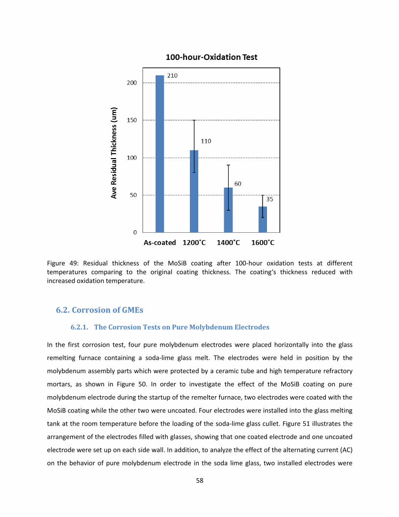
58
Figure 49: Residual thickness of the MoSiB coating after 100-hour oxidation tests at different temperatures comparing to the original coating thickness. The coating‘s thickness reduced with increased oxidation temperature.
6.2. Corrosion of GMEs
6.2.1. The Corrosion Tests on Pure Molybdenum Electrodes
In the first corrosion test, four pure molybdenum electrodes were placed horizontally into the glass
remelting furnace containing a soda-lime glass melt. The electrodes were held in position by the
molybdenum assembly parts which were protected by a ceramic tube and high temperature refractory
mortars, as shown in Figure 50. In order to investigate the effect of the MoSiB coating on pure
molybdenum electrode during the startup of the remelter furnace, two electrodes were coated with the
MoSiB coating while the other two were uncoated. Four electrodes were installed into the glass melting
tank at the room temperature before the loading of the soda-lime glass cullet. Figure 51 illustrates the
arrangement of the electrodes filled with glasses, showing that one coated electrode and one uncoated
electrode were set up on each side wall. In addition, to analyze the effect of the alternating current (AC)
on the behavior of pure molybdenum electrode in the soda lime glass, two installed electrodes were

59
electrically connected (in a diagonal direction)while the other two were not (in Figure 51). It took nearly
24 hours for the startup of the remelter furnace to reach the target temperature (1100°C) and then two
electrodes started to deliver the electricity into the molten glass. The four electrodes were immersed in
the molten glass for 100 hours. During the test, the current intensity was measure by the current meter
and the average current density was around 0.8 A/cm2.
Figure 50: The schematic sketch (left) showing the electrode and the molybdenum assembly parts with the ceramic tubes and high temperature refractory mortar, and the picture (right) of the molybdenum electrode assembly were protected by the ceramic tubes filled with mortars.

60
Figure 51: The picture of the four-electrode arrangement in the glass melting tank with soda-lime glass beads. Electrodes were loaded with the glass beads at room temperature before the corrosion test.
After the 100-hour corrosion test, the electrodes pulled out of the molten glass were covered by the
adhering glasses, as presented in Figure 52. Most of the attached glasses were removed from the
electrodes by mechanical impact. Visual examinations of coated electrodes surface indicated there was
almost no difference with or without the current load. The corrosion test did not seem to cause
noticeable corrosion damage on the surface of the coated electrodes with current load. While, it was
observed that uncoated electrodes were more corroded than the coated electrodes according to the
yellow deposits left on the surface. The reason probably is that the electrodes without the protection
from the MoSiB coating were oxidized when the oxygen was present during startup. The evidence of the
yellow deposits observed on the surface of the uncoated electrodes is assumed as the formation of the
volatile molybdenum trioxide (MoO3) during startup when the molten glass was not molten and able to
cover the whole electrode. Further, between two uncoated electrodes, more MoO3 were found on the
electrode electrically connected suggesting that the oxidation may cause more damage to the electrode
when the electricity is introduced to the electrode for providing heat to the molten glass.

61
Figure 52: The pictures of the molybdenum electrodes after the first corrosion test, (a) coated sample without AC, (b) coated sample with AC, (c) uncoated sample with AC, and (d) uncoated sample without AC. There were more yellow deposits observed on uncoated electrodes than on coated ones. Also more yellow deposits were observed on the uncoated electrode with AC than the uncoated electrode without AC.
One metallurgical sample was cut from each tested electrode and analyzed by using scanning electron
microscopy with X-ray microanalysis. Figure 53 shows the cross-section of the glass-electrode interface
of the samples which are depicted in Figure 52. Compared to Figures 53 (c) and (d), Figures 53 (a) and (b)
illustrates that there was no molybdenum oxides that had diffused into the substrate through grain
boundaries due to the MoSiB coating. Furthermore, as shown in Figure 53 (a), the MoSiB coating
succeed in protecting the molybdenum electrode from oxidation and corrosion attacks after the 100-
hour test when no current was applied. Continued evaluation of the electrically connected electrodes,
Figures 53 (a) and (b) clarifies that alternating current increased the consumption of the coating during
the test. Moreover, compared to the electrodes without current shown in Figures 53 (a) and (d), more
molybdenum dioxide (MoO2) and/or silica (SiO2) had diffused into the substrate when the electrodes
delivered electricity into the molten glass illustrated in Figures 53 (b) and (c). Therefore the alternating
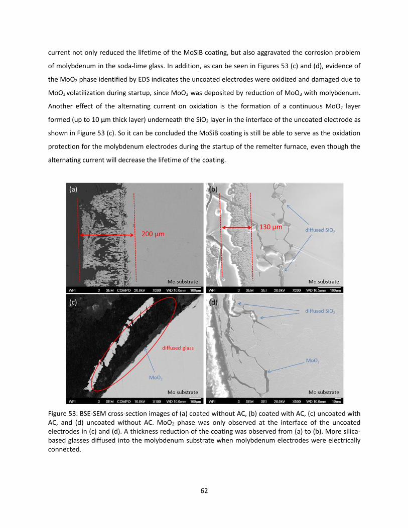
62
current not only reduced the lifetime of the MoSiB coating, but also aggravated the corrosion problem
of molybdenum in the soda-lime glass. In addition, as can be seen in Figures 53 (c) and (d), evidence of
the MoO2 phase identified by EDS indicates the uncoated electrodes were oxidized and damaged due to
MoO3 volatilization during startup, since MoO2 was deposited by reduction of MoO3 with molybdenum.
Another effect of the alternating current on oxidation is the formation of a continuous MoO2 layer
formed (up to 10 μm thick layer) underneath the SiO2 layer in the interface of the uncoated electrode as
shown in Figure 53 (c). So it can be concluded the MoSiB coating is still be able to serve as the oxidation
protection for the molybdenum electrodes during the startup of the remelter furnace, even though the
alternating current will decrease the lifetime of the coating.
Figure 53: BSE-SEM cross-section images of (a) coated without AC, (b) coated with AC, (c) uncoated with AC, and (d) uncoated without AC. MoO2 phase was only observed at the interface of the uncoated electrodes in (c) and (d). A thickness reduction of the coating was observed from (a) to (b). More silica-based glasses diffused into the molybdenum substrate when molybdenum electrodes were electrically connected.

63
In order to study the effect of the alternating current and the MoSiB coating on the corrosion
mechanism of pure molybdenum, the second corrosion test was carried on with four molybdenum
electrodes which were all electrically connected. The electrode arrangement was the same as the first
test: two of them were coated and each furnace side-wall was installed with one coated and one
uncoated electrode, horizontally. Four electrodes were still heated in the soda-lime glass at 1100˚C, but
the time period was increased up to 168 hours after the 24-hour startup of the remelter furnace. The
average current density was about 1.1 A/cm2, almost 40% higher than the first test. Figure 54 shows the
electrodes after being pulled out of the molten glass at the end of the second corrosion test. There was
still no significant degradation observed on the surface of the coated electrode. In contrast, the surface
of the uncoated electrode seemed rough and uneven, containing lots of glass deposits, not as smooth as
the surface of the coated electrode.
Figure 54: Two pictures of (a) coated and (b) uncoated molybdenum electrode samples after the second corrosion test with AC current. The surface of the uncoated electrode did not seem as smooth as the coated electrode’s surface after the 168-hour corrosion test.
Metallographic samples were cut from the tip of the electrodes with the worst corrosion attack during
the heating process with current. Evaluations of the uncoated molybdenum electrode using the
scanning electron microscopy with X-ray microanalysis suggested the diffused silica layer at the glass-
electrode interface of the uncoated sample was present, with a thickness up to 700 μm as shown in
Figure 55 (a). As also shown in Figure 55 (a), some quantity of molybdenum was apparently detached
from the electrode surface without alloying with other glass components and absorbed in the molten
glass. The MoO2 phase was also found underneath the diffused silica layer. As illustrated in Figure 55 (b),
MoO2 formed a continuous layer 10 μm thick at the interface. Compared to the first test, the
molybdenum dioxide layer at the interface of the uncoated electrodes had not increased with increased

64
current density or the corrosion time. However, the thickness of the silica layer increased at the
interface with higher current density and longer corrosion time.
Figure 55: BSE-SEM images of the uncoated electrode with AC after the second experiment. SiO2 phase diffused into the molybdenum substrate and formed a very thick and continuous layer shown in (a). MoO2 phase also formed a continuous layer with 10 um thick underneath the SiO2 layer shown in (b), higher magnification of (a).
Further examinations of the coated molybdenum electrode using SEM/EDS revealed the intergranular
attack and fracture at the glass-electrode interface. Diffused SiO2 was only observed at the grain
boundaries on the near-surface region of the electrode (in Figure 56). SiO2 was in the form of continued
precipitates indicating the SiO2 broke through the coating and diffused into the electrode, and then
precipitated at the grain boundaries. Grain coarsening was observed along grain boundaries and formed
a continuous layer. The affected region was about 375 μm deep from the surface. With higher current
density and longer corrosion time, a thickness reduction of the MoSiB coating was also observed at the
interface (~100 μm left on the surface). However, no MoO2 phase was identified at the interface,
indicating the coated molybdenum had not oxidized during startup, although the protective coating was
degraded.

65
Figure 56: SEM image of the coated electrode with AC after the second experiment. SiO2 phase broke through the coating and diffused into the molybdenum substrate. Diffused SiO2 formed a continuous layer along grain boundaries and the maximum penetration depth is up to 375 μm. The residual coating’s thickness was about 100 μm.
Figure 57 summarizes the results of the diameter loss in µm of all molybdenum electrodes from two
previous corrosion tests. Figure 58 shows the maximum penetration depth of the diffused glass
components and compounds for all molybdenum electrodes. These two graphs agree with the previous
work that two different failure mechanisms acted on molybdenum electrodes during the glass melting
process: superficial oxidation and intergranular corrosion. First, the surface removal is primarily caused
by superficial oxidation (the mass loss of molybdenum trioxides), because uncoated electrodes are
subject to severe oxidation problem during startup. As shown in Figure 57, compared to the coated
electrodes, significant diameter loss was observed on the uncoated electrodes. Irregular attack occurs in
the case of uncoated electrodes, the corrosion being considerably increased in the neighborhood of
precipitated silica and molybdenum oxides, with molybdenum loss in the form of metallic particles.
Further, the diameter loss increased not only when the current was loaded, but also through the effect

66
of the increased current density despite the alternating current having no effect on the oxidation
process. Most likely the alternating current increases the molybdenum corrosion rate by accelerating
the reaction speed between molybdenum and glass components occurring along the grain boundaries at
the glass-electrode interface. Low-melting compounds spread out along grain boundaries more quickly
when electrically loaded resulting in the loss of molybdenum grains from the electrode. The more glass
deposits penetrated into the molybdenum electrode, the more molybdenum was removed from the
electrode surface without alloying with other glass components and being absorbed in the molten glass.
As illustrated in Figure 58, it is obvious that glass penetrated much deeper into the uncoated electrodes
than the coated electrodes suggesting that oxidation damage exacerbates the corrosion problem of
molybdenum. Without the protection of the MoSiB coating, molybdenum oxides will easily form low-
melting compounds with molybdenum and glass components along grain boundaries and the total
amount of precipitated glass components increase at the interface during the glass melting process. In
contrast, with the protection of the MoSiB coating, only silica reacts with molybdenum along grain
boundaries. The MoSiB protects molybdenum from oxidation damage during startup and the corrosion
reactions are partly hindered on the MoSiB coating structure due to the absence of molybdenum oxides.
Lastly, the AC current accelerates the corrosion rate of molybdenum while it does not affect oxidation of
molybdenum. Corrosion tests on molybdenum carried out with and without electrical load showed that
penetration depth increased under electrical loading. Based on the penetration depth for the electrodes
loaded with different current densities, the precipitates also diffused deeper with higher current density.
So corrosion rate of molybdenum is not only affected by the current load, but increases with increasing
current density as well.

67
Figure 57: The chart showing the diameter loss of the molybdenum electrodes after being corroded in the molten soda-lime glass. The loss in percentage was calculated before and after the test.
Figure 58: Maximum penetration of SiO2 which diffused into the molybdenum substrate.
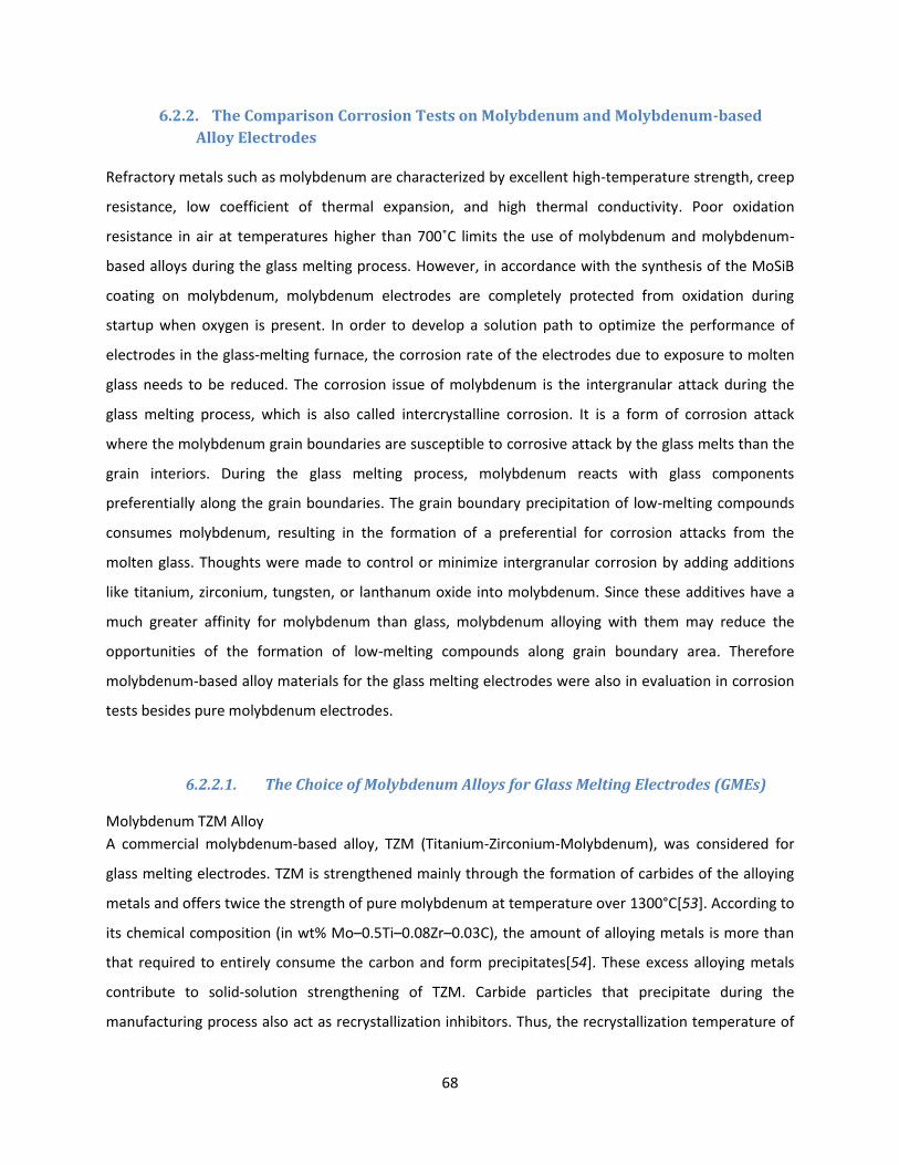
68
6.2.2. The Comparison Corrosion Tests on Molybdenum and Molybdenum-based
Alloy Electrodes
Refractory metals such as molybdenum are characterized by excellent high-temperature strength, creep
resistance, low coefficient of thermal expansion, and high thermal conductivity. Poor oxidation
resistance in air at temperatures higher than 700˚C limits the use of molybdenum and molybdenum-
based alloys during the glass melting process. However, in accordance with the synthesis of the MoSiB
coating on molybdenum, molybdenum electrodes are completely protected from oxidation during
startup when oxygen is present. In order to develop a solution path to optimize the performance of
electrodes in the glass-melting furnace, the corrosion rate of the electrodes due to exposure to molten
glass needs to be reduced. The corrosion issue of molybdenum is the intergranular attack during the
glass melting process, which is also called intercrystalline corrosion. It is a form of corrosion attack
where the molybdenum grain boundaries are susceptible to corrosive attack by the glass melts than the
grain interiors. During the glass melting process, molybdenum reacts with glass components
preferentially along the grain boundaries. The grain boundary precipitation of low-melting compounds
consumes molybdenum, resulting in the formation of a preferential for corrosion attacks from the
molten glass. Thoughts were made to control or minimize intergranular corrosion by adding additions
like titanium, zirconium, tungsten, or lanthanum oxide into molybdenum. Since these additives have a
much greater affinity for molybdenum than glass, molybdenum alloying with them may reduce the
opportunities of the formation of low-melting compounds along grain boundary area. Therefore
molybdenum-based alloy materials for the glass melting electrodes were also in evaluation in corrosion
tests besides pure molybdenum electrodes.
6.2.2.1. The Choice of Molybdenum Alloys for Glass Melting Electrodes (GMEs)
Molybdenum TZM Alloy
A commercial molybdenum-based alloy, TZM (Titanium-Zirconium-Molybdenum), was considered for
glass melting electrodes. TZM is strengthened mainly through the formation of carbides of the alloying
metals and offers twice the strength of pure molybdenum at temperature over 1300°C[53]. According to
its chemical composition (in wt% Mo–0.5Ti–0.08Zr–0.03C), the amount of alloying metals is more than
that required to entirely consume the carbon and form precipitates[54]. These excess alloying metals
contribute to solid-solution strengthening of TZM. Carbide particles that precipitate during the
manufacturing process also act as recrystallization inhibitors. Thus, the recrystallization temperature of

69
TZM is approximately 250°C higher than pure molybdenum[55]. The formation of titanium carbide (TiC)
and zirconium carbide (ZrC) at the grain boundaries in TZM alloys inhibit grain growth and the related
failure of the base metal as a result of corrosion cracking along grain boundaries[56]. The TZM alloy was
investigated in the corrosion tests to evaluate whether the existence of TiC and ZrC would lower the
content of the low-melting compounds from the corrosion reaction between molybdenum and glass
components in the grain boundary region. Further, it was theorized that grain size plays a role in the
corrosion mechanism of molybdenum and molybdenum alloys during the glass melting process.
However, the effect of the grain size on the corrosion behavior of molybdenum in the molten glass was
still undefined. Molybdenum and molybdenum based alloys used today can be produced by two primary
consolidation methods; vacuum arc-casting (VAC) and powder metallurgy (PM). In the vacuum arc
furnace, complete melting and blending of molybdenum metal and alloys takes place to assure a
homogeneous material and provide a relatively coarse grain structure. Molybdenum metal and alloys
produced by powder metallurgy techniques generally have a finer grain structure. The fine grain size is
generally tougher and more ductile as compared with the coarse grain size. However the grain size
produced by powder metallurgy may be so small that the grain boundary area may be several times
larger than in arc-casting metals. Grain size’s dilemma: Finer grains with much higher grain boundary
area may have more preferential paths for corrosion while coarse grain molybdenum metal and alloys
may disintegrate (grains fall out) or lose its strength. So both powder metallurgy and arc-casting TZM
alloys were investigated in the corrosion tests in order to define the effectiveness of grain sizes of
molybdenum alloys. In addition, the powder metallurgy and arc-casting pure molybdenum metals were
also analyzed in the tests with TZM alloys. All four kinds of materials were provided by H.C. Starck, Inc.
Molybdenum - 30wt% Tungsten Alloy (Mo-30W)
The Mo-30W alloy was also chosen as the candidate material for the glass melting electrode due to its
high strength at high temperatures, high melting point (2832˚C), and resistance to impact and thermal
shock. According to the tungsten-molybdenum binary phase diagram[57], tungsten forms a continuous
solid solution with molybdenum, which indicates that molybdenum (or tungsten) elements completely
dissolve in the remaining bcc tungsten (or molybdenum) phase. As tungsten is added into molybdenum,
the alloy is gradually strengthened by the mechanism of substitutional solid solution strengthening[58].
The Mo-30W alloys were produced by vacuum arc-casting in H.C. Starck, Inc, containing a coarse grained
structure. The glass melting electrodes made of Mo-30W alloys were examined in the corrosion tests
and compared with other molybdenum metal and alloys.

70
Oxide Dispersion Strengthened (ODS) Molybdenum Alloy
The ODS molybdenum alloy with Lanthanum (La) oxide was another material that was evaluated for
glass melting electrodes. The ODS molybdenum alloy was developed for high temperature applications
and possesses excellent high temperature strength and creep resistance[59]. The strength of ODS
molybdenum alloys is improved through oxide dispersions. These finely dispersed particles retard
dislocation motion, increasing material strength[60]. The ODS molybdenum alloy doped with the oxide
(La2O3) from the test[61] had high strength and creep resistance at high temperature. The oxide is
present as dispersed particles in the matrix and along grain boundaries[62]. La2O3 particles not only act
as nucleation sites for strain free grains, but also help retard grain growth during recrystallization. Arc-
casting and powder metallurgy molybdenum metals have a recrystallization temperature of around
1200˚C and the recrystallized grains are equiaxed and larger than the microstructure before annealing
while the ODS molybdenum alloy’s recrystallization temperature is higher and grains maintain high
aspect ratio after heat treatments[63]. It is thought that La2O3 particles segregating to the grain
boundaries reduces the possibility of grain boundary transport by diffusion, leading to the decreased
mass loss of molybdenum substrate. The Lanthanum doped ODS molybdenum alloy tested in this study
was produced commercially through the powder metallurgy process in H.C. Starck, Inc.
The six selected molybdenum metal and alloy samples (the PM and arc-casting molybdenum and TZM
alloys, the Mo-30W alloy, and the ODS-molybdenum alloy) were etched by the modified molybdenum
etchant (Potassium ferricyanide 75g, sodium hydroxide 10g, and distilled water 500mL) for microscopy.
Optical micrographs, Figures 59 and 60 reveal the grain structures in the six etched samples. Samples
produced by powder metallurgy have finer grain size than the ones manufactured by arc-casting. Mo-
30W sample has the coarsest grained structure while ODS-molybdenum sample has the finest grained
structure among six samples presented in Figure 60.
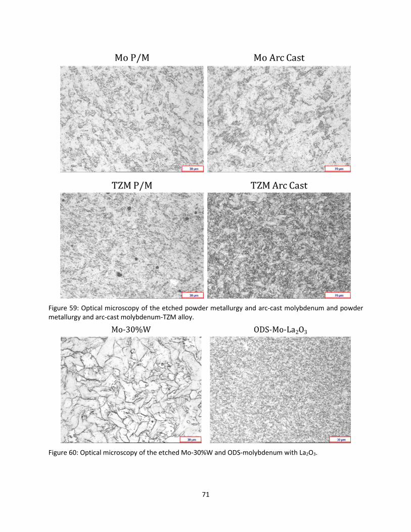
71
Figure 59: Optical microscopy of the etched powder metallurgy and arc-cast molybdenum and powder metallurgy and arc-cast molybdenum-TZM alloy.
Figure 60: Optical microscopy of the etched Mo-30%W and ODS-molybdenum with La2O3.

72
Single Crystal Molybdenum
Molybdenum generally exhibits the intergranular brittleness when it is in the recrystallized condition. In
fact, the grain boundary brittleness in molybdenum is not only caused by impurity segregation and
precipitation at grain boundaries[64, 65], but is primarily attributed to the intrinsic weakness in the grain
boundary[66] as well. Interstitial impurities, such as carbon, oxygen and nitrogen, only affect the grain
boundary brittles as a secondary factor. Besides alloying molybdenum with elements to suppress the
segregation of low-melting compounds to grain boundaries, eliminating grain boundaries is another
potential solution to conquer the corrosion problem in the molten glass by eliminating the diffusion
paths to corrosion attack. The absence of the defects associated with grain boundaries can also give
metals better mechanical properties, more stable microstructures, and higher temperature creep
resistance than polycrystalline metal does. Lastly, the single crystal molybdenum metal was considered
as a potential alternative to be the new material for glass melting electrodes.
6.2.2.2. Glass Melting Electrodes Preparation for the Comparison Corrosion Tests
All seven metals were machined to the size as shown in the schematic sketch in Figure 16 for the
corrosion test. In order to study the effect of the MoSiB coating on the corrosion behavior of the coated
GMEs, the two-step synthesis of the MoSiB coating was also conducted on all seven electrodes as
previously described. The thickness gains of electrodes’ diameter were monitored during the two-step
synthesis shown in Figure 61, indicating the MoSiB coating successfully developed and attached on the
surface of GMEs. During the synthesis of the MoSiB coating on the electrodes, coupons from each metal
were simultaneously coated to monitor the coating process on different molybdenum alloys. In general,
the as-packed surface was very smooth and the appearance of as-packed samples was blackish in color.
After conditioning, the electrode surface had a glassy grey look. Back-scattered SEM cross-section
images of the TZM alloy, the Mo-30W alloy, and the ODS-molybdenum alloy after coating, Figures 62-64,
show the coating structures on molybdenum alloys are also adherent and uniform.

73
Figure 61: Diameter change of GMEs after being coated by the two-step synthesis.
Figure 62: Back-scattered SEM microstructure images of a) the as-packed TZM alloy composed of MoSi2 outer layer and a continuous boride layer underneath b) the same alloy after conditioning showing the MoSiB coating structure. Thickness growth on coating structure indicates that phase conversion started to develop between the disilicide and boride layers.

74
Figure 63: Back-scattered SEM microstructure images of a) the as-packed Mo-30W alloy composed of (Mo,W)Si2 outer layer and a continuous boride layer underneath b) the same alloy after conditioning showing the MoSiB coating structure. Thickness growth on coating structure indicates that the phase conversion started to develop between the disilicide and boride layers.
Figure 64: Back-scattered SEM microstructure images of a) the as-packed ODS-Mo alloy composed of MoSi2 outer layer and a continuous boride layer underneath b) the same alloy after conditioning showing the MoSiB coating structure. Thickness growth on the coating structure indicates that phase conversion started to develop between the disilicide and boride layers.
As illustrated in Figures 62-64, the MoSiB coatings were successfully formed on molybdenum alloys after
the two-step synthesis. The coating process was dominant by the diffusion of silicon, and the
multilayered coating structure formed a continuous compositional gradient. The formation of the
disilicide phase with continuous boride layer developed on molybdenum alloys after the co-pack
cementation (with a 35-1 ratio of weight of Si to B powder sources) at relatively low temperature
(1050˚C) after 50 hours. The oxidation resistance of the coating on molybdenum alloys was verified
during the conditioning process at 1450˚C in air for 24 hours. The evidence of the thickness growth of

75
the coatings in Figures 62-64 shows the development of the oxidation resistance layer of the MoSiB
coating which is comprise of molybdenum silicide phase and borosilicides. In addition, the growth on the
boride layer shown between red dotted lines (in Figures 62-64) reveals the formation of the diffusion
barrier layer of the MoSiB coating. In the case of the TZM alloy, the fracture toughness is improved by
the micro-alloying additions, however, the toughness of the MoSi2 and T1+T2 layer is unlikely to be
enhanced by Zr and Ti [67]. Unlike the pure molybdenum in the absence of tungsten, molybdenum
diffused outwardly (rather than tungsten) to enhance the coating in the Mo-30W alloy, because the
diffusion of molybdenum is higher than the diffusion of tungsten[68]. So the coating on Mo-30W was
formed by the inward diffusion of silicon and outward diffusion of molybdenum as well. In addition,
small amount of tungsten trioxide (WO3) was detected in the silica layer after the coating synthesis
shown in the red circle in Figure 63 (b), indicating that WO3 has the lower volatility than molybdenum
trioxide. Alloys containing a dispersoid reach steady state much earlier than the dispersion free
alloys[69]. When adding oxide dispersions in the form of La2O3 into molybdenum, the growth rate of the
coating was reduced (60-μm thickness grown on TZM and Mo-30W alloys compared to 40-μm thickness
grown on ODS-Mo) shown in Figure 64. The addition of La2O3 yielded a dense and compact coating
structure as a consequence of decreased silicon diffusion inward to molybdenum substrate due to the
enhanced microstructure.
6.2.2.3. Results of the Corrosion Tests
In order to evaluate the corrosion resistance of the MoSiB coating without the interference from
oxidation, all coated electrodes were placed into the furnace tank after the glass melted when oxygen
was limited by the molten glass, skipping the startup of the remelter furnace. Seven coated electrodes
were exposed to the comparison corrosion tests without the load of current in two different glass melts,
soda-lime glass and borosilicate glass.
During the first test seven coated GMEs were placed in the soda lime glass melt at 1200˚C for 12 days.
Figure 65 presents the picture of seven coated GMEs’ appearance before and after the test. Visual
examinations on the coated electrodes indicate that molten glass was present on the surface even after
most of the attached glasses were removed by mechanical impact. All electrodes’ surfaces were uneven
and rough expect for the single crystal molybdenum electrode’s surface was smooth without attached
glasses.
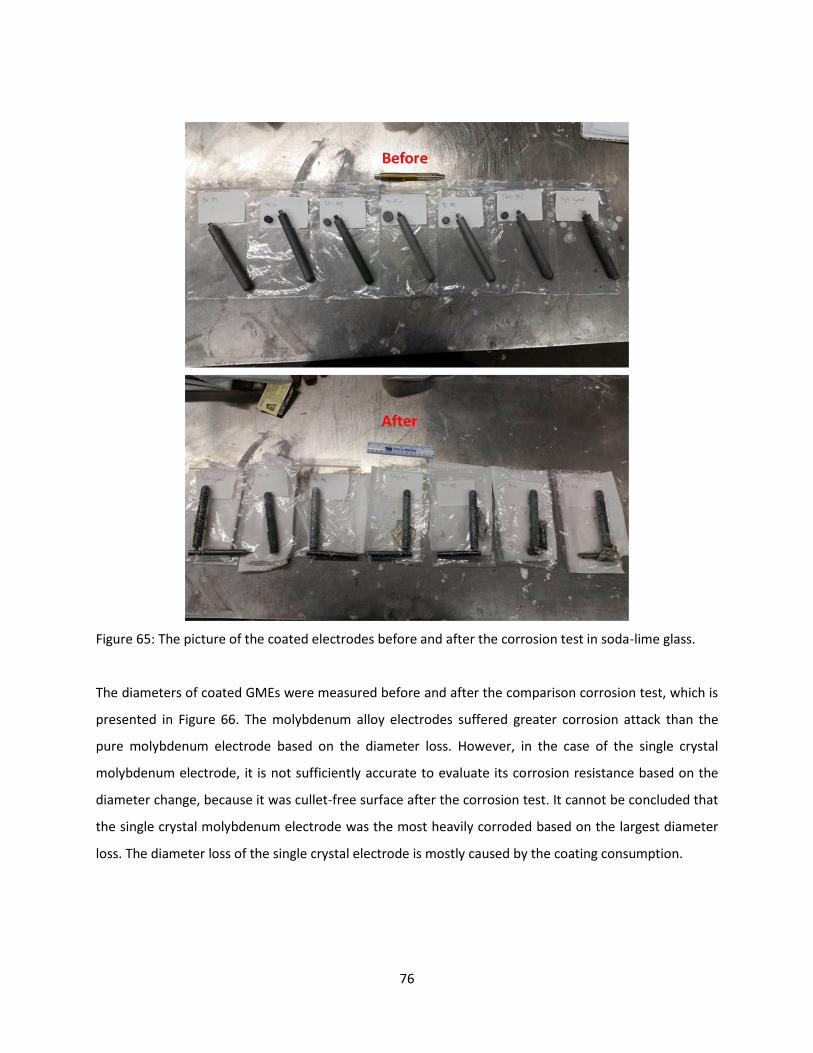
76
Figure 65: The picture of the coated electrodes before and after the corrosion test in soda-lime glass.
The diameters of coated GMEs were measured before and after the comparison corrosion test, which is
presented in Figure 66. The molybdenum alloy electrodes suffered greater corrosion attack than the
pure molybdenum electrode based on the diameter loss. However, in the case of the single crystal
molybdenum electrode, it is not sufficiently accurate to evaluate its corrosion resistance based on the
diameter change, because it was cullet-free surface after the corrosion test. It cannot be concluded that
the single crystal molybdenum electrode was the most heavily corroded based on the largest diameter
loss. The diameter loss of the single crystal electrode is mostly caused by the coating consumption.

77
Figure 66: Diameter change of coated GMEs before and after the corrosion test in the molten soda-lime glass. The diameter loss was observed on every electrode after the test.
SEM observations on polished glass-electrode interfaces of all coated electrodes reveal the corrosive
attack after the 12-day corrosion test. Figures 67 and 68 show the cross-section of both powder
metallurgy and arc cast pure molybdenum and molybdenum TZM alloy electrode. Compared to the
electrode produced by the powder metallurgy method in Figures 67 (a) and 68 (a), more corrosive attack
was observed on the electrode produced by the arc casting technique in Figures 67 (b) and 68 (b). First,
less residual coating was discovered on arc-cast electrodes than on powder metallurgy electrodes.
Second, Figures 69 shows the fact that there are more compounds comprised of glass components and
molybdenum segregating to grain boundaries inside of the arc-cast electrodes than the powder
metallurgy electrodes.

78
Figure 67: SEM microstructure images of a) powder metallurgy (PM) molybdenum, b) arc-casting molybdenum. Residual coating was illustrated between the red dotted lines.
Figure 68: SEM microstructure images of a) powder metallurgy (PM) molybdenum TZM alloy, b) arc-casting molybdenum TZM alloy. Residual coating was illustrated between the red dotted lines.
Figure 69: SEM microstructure images of a) arc-casting molybdenum, b) arc-casting TZM alloy. Diffused compounds segregated to the grain boundaries in arc-casting electrodes.

79
The glass-electrode interfaces on ODS-Mo alloy and Mo-30W was presented in Figures 70 (a) and (b),
indicate the molten glass broke through the coating and diffused into the substrate through the grain
boundaries. No residual coating was observed at the interface on either electrode, indicating that both
electrodes were corroded more than pure molybdenum and TZM alloy. This is in agreement with the
diameter change chart, Figure 66. According to the SEM/EDS results, the diffused compounds penetrate
deeper into the ODS-Mo electrode (500 μm in max. penetration) than into the Mo-30W electrode (400
μm in max. penetration). However, there is a large amount of precipitated compounds consisted of
molybdenum (with tungsten) and glass components along grain boundaries on Mo-30W electrode,
which is much more than those at ODS-Mo electrode’s grain boundaries.
Figure 70: SEM microstructure images of a) ODS-Mo alloy, b) Mo with 30 wt% W alloy.
As illustrated in Figure 71, it is clear the coated single crystal electrode showed the least corrosive attack
from the soda-lime glass. There was no evidence of cracks filled with glasses or diffused compounds
inside of the electrode. The residual coating’s thickness was still 120 μm after the corrosion test, while
some part of the coating was removed from the surface by molten glasses shown in the red circle in
Figure 71 (b).

80
Figure 71: SEM microstructure images of a) single crystal molybdenum, b) back-scattered SEM images of the same electrode. Residual coating was illustrated up to 120 μm between the red dotted lines in (a) and some part of the coating was removed from the surface shown in the red circle in (b).
All GMEs underwent corrosive attack from the soda-lime glass melt after the 12-day corrosion test at
1200˚C except for the single crystal molybdenum electrode. These results demonstrate the mechanism
of corrosion of pure molybdenum and molybdenum base alloys is intergranular attack. This is caused by
the redox reaction between molybdenum and glass components from the soda-lime glass melt. Glass
components are reduced by molybdenum to subsequently form relatively low-melting compounds
resulting in the dissolution of molybdenum into the melts. Those compounds would considerably rather
segregate to grain boundaries than in grains and directly enhance the penetration of the glass deposits
and weaken the electrode’s strength. Greater attack of glass-molybdenum components was found in
arc-cast electrodes than in powder metallurgy electrodes suggesting that the intergranular corrosion
propagates more easily in a network of large grains than fine grains (shown in Figure 69). The reason is
probably because the impurity density is usually higher in coarse-grained structure than in fine-grained
structure of the same purity. In the case of TZM electrodes in Figure 68, the precipitation of glass-
molybdenum compounds diffused farther from the surface than in pure molybdenum electrodes. This
indicates that alloy additions of zirconium and titanium which formed carbides in molybdenum are
susceptible to the dissolution and precipitation of glass-molybdenum compounds in the grain boundary
areas. It can be assumed the carbides formed along the grain boundaries increased the effective
solubility of glass components in molybdenum. For the Mo-30W electrode in Figure 70 (b), good
agreement can be seen in the relationship between the intergranular corrosion and the grain size,
greater intergranular corrosion occurs in coarse-grained structure than in finer-grained structure. Since
the Mo-30W electrode was produced by vacuum arc casting, it has a relatively coarse grain structure

81
(also shown in the optical microscopy in Figure 60). This structure facilitated the segregation of glass
components along grain boundaries in molybdenum leading to the grain coarsening, thus intensifying
problems of intergranular corrosion. In addition, Mo-30W electrode exhibits the poorest corrosion
resistance among all GMEs because of the different properties of tungsten oxides as well. Tungsten
trioxide (WO3) is to blame for the worst behavior of corrosion resistance, because WO3 stayed in the
SiO2 layer after the synthesis of the MoSiB coating. The cracks in the coating structure were also filled
with the mixture of SiO2 with WO3, thereby disturbing the protective coating and promoting brittle
intergranular corrosion. Concerning the ODS-Mo electrode in Figure 70 (a), the depth of internal glass-
molybdenum compounds precipitation along grain boundaries was higher than pure molybdenum
electrode, because lanthanum increases the fluidity of the SiO2 (with B2O3) phase. In addition, due to the
finer microstructure formed, a larger amount of internal grain boundaries increase the intergranular
corrosion rates leading to a greater penetration into the substrate. However, there is no grain
coarsening observed in the fine-grained structure because of the tougher grain boundaries compared to
the coarse-grained structure.
In the second test seven coated GMEs were placed in the borosilicate glass melt for 12 days without a
current load but at higher operating temperature (1300˚C). All GMEs were placed into the tank after the
glass cullet melted in order to avoid the oxidation damage from the startup of the remelter furnace.
Figure 72 shows the seven GMEs before and after the test. Visual examination indicates the GMEs
surface was non-uniform after exposure to the borosilicate glass. The TZM and ODS molybdenum
electrodes’ surface had mottled color patterns. The diameter change of coated GMEs was also
measured after the attached glasses were removed by mechanical impact, as shown in Figure 73. The
second comparison corrosion test has similar results of the diameter change to the first one in soda-lime
glass melt. Molybdenum alloys electrodes were more corroded than pure molybdenum electrodes in
borosilicate glass. However, again, corrosion on single crystal molybdenum electrode cannot be
evaluated with accuracy by the diameter loss method due to the deposited glass cullet free surface and
the coating consumption.

82
Figure 72: The picture of the coated electrodes before and after the corrosion test in borosilicate glass.
Figure 73: Diameter change of coated GMEs before and after the corrosion test in the molten borosilicate glass. The diameter loss was observed on every electrode after the test.

83
SEM observations on polished glass-electrode interfaces of all coated electrodes reveal the corrosive
attack after exposure in borosilicate glass. After 12 days the outer and porous coating region had been
severely attacked by the molten glass, but the inner zones (diffusion barrier layer) remained unchanged
as shown between the red dotted lines in Figures 74 (a), 75 (a), 77, and 78. The diffusion barrier layer in
the MoSiB coating contained borosilicide and boride phases and functions to heal the outer T1 phase
layer. The MoSiB coating reacted slowly with the borosilicate glass probably due to the presence of
boron trioxide (B2O3) in the borosilicate glass. The presence of B2O3 in the glass melt is advantageous to
the MoSiB coating because it decrease the viscosity of the borosilicate layer (SiO2+B2O3), providing
enough flow for the diffusion barrier layer to heal small cracks or defects that appear in the coating
structure. This is also desirable because it allows the coating structure to self-heal from the damage
caused by the impact of molten glass, even though boron evaporates rapidly at 1300˚C.
The MoSiB coating is not the most effective option to protect molybdenum and molybdenum alloys
from corrosion, even though it reacted slowly with the borosilicate glass. As illustrated in Figures 74 (b)
and 75 (b), SEM/EDS analysis shows almost a complete loss of the diffusion barrier layer in the residual
coating structure. Compounds consisting of glass and molybdenum underneath the coating structure
between the red dotted lines indicate that the compounds had penetrated through the whole coating
structure and into the arc cast electrode material. In addition, some cracks filled with glass were
detected inside of arc cast electrodes in Figures 74 (c) and 75 (c), suggesting that precipitation of
diffused compounds in coarse-grained structure (up to 600 μm) was much higher than in fine-grained
structure. These behaviors agree the previous conclusion that electrodes produced by arc casting
suffered more corrosion from the melts than electrodes produced by powder metallurgy. Concerning
the TZM electrodes, SEM observations on glass-electrode interfaces reveal that more molybdenum was
removed from the TZM electrodes in Figure 75 than from the pure molybdenum electrodes in Figure 74,
which agrees with the results of the diameter change of the electrodes. More redox reactions between
the glass and molybdenum due to corrosion increases the amount of molybdenum absorbed in the
melts.

84
Figure 74: BSE-SEM microstructure images of the glass-electrode interface of a) powder metallurgy (PM) molybdenum, b) arc-casting molybdenum, and c) the precipitation of diffused glass inside of the arc casting molybdenum electrode.

85
Figure 75: BSE-SEM microstructure images of the glass-electrode interface of a) powder metallurgy (PM) TZM, b) arc-casting TZM, and c) the precipitation of diffused glass inside of the TZM produced by arc casting.

86
As shown in Figure 76, the corrosion problem in ODS molybdenum electrode is also severe after being
tested in borosilicate glass. The MoSiB coating on ODS molybdenum electrode was totally dissolved
after the test. Compounds consisting of molybdenum and glass components were identified inside of
the electrode underneath the residual coating structure shown between red dotted lines. Evidence of
large amounts of molybdenum detached from the surface also proves the corrosion issue of ODS
molybdenum electrode.
Figure 76: BSE-SEM microstructure images of the ODS molybdenum electrode after the test in borosilicate glass.

87
In the case of the Mo-30W electrode (Figure 77), the corrosion attack is lower in borosilicate glass than
in soda-lime glass. Although the outer region of the coating was broken down by the melt, the inner
zone of the coating (diffusion barrier layer) survived shown between red dotted lines and succeeded in
protect the electrode from the intrusion of the melt. Presumably, with the help of the MoSiB coating’s
slower reaction with borosilicate glass, the diffusion barrier layer helped to prevent the diffusion of the
glass melt and no glasses were observed inside of the Mo-30W electrode.
Figure 77: BSE-SEM microstructure images of the Mo-30W electrode after the test in borosilicate glass.

88
The single crystal electrode with the coating again survived from the 12-day corrosion test. The coating
remained unchanged with up to 155 μm thickness after the test in Figure 78. It is also clear that no
evidence of cracks filled with glass or diffused compounds were observed inside of the electrode.
Figure 78: BSE-SEM microstructure images of the single crystal molybdenum electrode after the test in borosilicate glass.
Figure 79 illustrates the maximum penetration depth of diffused glass components and compounds in
GMEs after corrosion tests in soda-lime and borosilicate glasses. The results show that the glass
components and compounds penetrate deeper into the molybdenum alloy electrodes than into pure
molybdenum electrodes. The additions alloying with molybdenum did not increase the corrosion
resistance of molybdenum, on the contrary, they increased the solubility of the glass components into
molybdenum. The coated ODS molybdenum and Mo-30W electrodes were less corroded in borosilicate
glass than in soda-lime glass because the MoSiB coating reacted slower with borosilicate glass than with
soda-lime glass. However, the MoSiB coating cannot protect electrodes from corrosion attacks in other
glass melts except for the borosilicate glass. Additionally, the result of intergranular corrosion in arc-
casting electrodes is worse than that in powder metallurgy electrodes, although grain boundaries are
less in arc-casting electrodes than in powder metallurgy electrodes. The reason of this is because of the
impurity density along grain boundaries. The interstitial impurities segregation at grain boundaries also
intensify intergranular corrosion. Impurity density at grain boundaries in coarse grained structure is

89
higher than that in fine grained structure, so intergranular corrosion occurs and propagates easier in
coarse grains than in fine grains. Lastly, there is no precipitation of glass from the melts inside the single
crystal molybdenum electrode after being tested in soda-lime or borosilicate glass.
Figure 79: Maximum penetration depth of melt into GMEs in soda-lime and borosilicate glass.
Compared to the behavior of molybdenum and molybdenum based alloys in borosilicate glass, the single
crystal molybdenum appears to be the optimal electrode for the glass melting furnace due to its highest
corrosion resistance to the glass melts.

90
7. Discussion
Based on the corrosion tests in this study, it was observed that two failure mechanisms acted on
molybdenum electrodes during melting: oxidation and intergranular corrosion. During startup of the
furnace, oxidation leading to mass loss of molybdenum trioxides can be eliminated via the application of
a MoSiB coating. This coating was verified in this study as a promising protective solution to oxidation of
molybdenum and molybdenum alloy electrodes during startup. The coating performance is attributed to
the formation of a continuous borosilica layer on the outer surface of the electrode, and the stability
and integrity of the inner layers is due to an oxidation resistant T1 layer and a diffusion barrier layer
underlying the T1 phase. Since the enhanced oxidation resistance of GMEs is assured by incorporation of
the MoSiB coating, the chemical resistance of molybdenum electrodes to glass melts becomes the key
characteristic to focus on to optimize GME performance in molten glasses.
After startup, as the glass batch is melted, the redox reaction of molybdenum with polyvalent ions (such
as iron, cobalt, and antimony) in the glass melts is the dominant factor of corrosion both with and
without the alternating current load. The redox reaction of the polyvalent ion “M” can be described by:
,
where Mm+ and M(m-n)+ are the oxidized and reduced ions, respectively; O2 is dissolved oxygen in the
glass melts; O2- is the oxygen ion. Therefore, in the molten glass, the molybdenum electrode is oxidized
by polyvalent elements from the melts as described by:
,
where M is polyvalent ions in the glass melts and n is the number of electrons involved in the reaction.
When an alternating current is applied to the electrodes, the metallic molybdenum is oxidized to the
ionic state during the anodic part of the alternating current cycle. During cathodic polarization, the
polyvalent ions are reduced rather than molybdenum ions, leading to the acceleration of electrode
corrosion by dissolving more molybdenum into the melts. Reaction products containing molybdenum
and glass components preferentially segregate to and spread out along grain boundaries by diffusion at
the glass-electrode interface. Intergranular corrosion is due to the grain boundary brittleness and
worsened by impurity segregation and precipitation at grain boundaries. This study shows that the
corrosion resistance of TZM alloys is inferior to pure molybdenum. Although the zirconium and titanium
additions to TZM tend to form carbides along grain boundaries which minimize and inhibit the
91
interstitial impurities segregation to the grain boundaries, these additions also increased the solubility of
the glass components in molybdenum along grain boundaries, accelerating the grain boundary corrosion
problem of molybdenum electrodes. From this study, molybdenum alloying with tungsten and
lanthanum oxides cannot improve the corrosion resistance of molybdenum electrodes, either. In the
case of the Mo-30%W alloy, the corrosion of molybdenum electrodes was increased by the formation of
tungsten trioxides on the outmost surface of the coating. In the case of ODS-Mo alloy, since the
lanthanum oxides increase the fluidity of the SiO2 phase, the corrosion resistance of ODS-Mo electrode
cannot be improved.
The results of intergranular corrosion in arc-cast electrodes are worse than in powder metallurgy
electrodes, although the amount of grain boundaries is less in arc-cast electrodes than in powder
metallurgy electrodes. The reason for this paradoxical situation is probably because of the impurity
density at grain boundaries. The interstitial impurities segregation to grain boundaries intensifies
intergranular corrosion. Impurity density at grain boundaries in a coarse grain structure is higher than
that in a fine grained structure, so intergranular corrosion seems to occur and propagate easier in coarse
grains than in fine grains. The intrinsic weakness in grain boundaries of molybdenum seems to be the
limitation to further applications of molybdenum for GMEs, while the impurity segregation to grain
boundaries also seems to be a factor to intergranular corrosion. Nevertheless, it is not yet known in
detail whether the amount of grain boundaries or the condition of grain boundaries is the primary factor
leading to intergranular corrosion.
However, by eliminating grain boundaries in molybdenum, the single crystal molybdenum was shown to
still be intact after corrosion tests in soda-lime and borosilicate glass melts over a temperature range of
1200°C to 1300°C. For improved total corrosion characteristics in molybdenum electrodes, it has been
proven that one should take selectively targeted corrosion-inhibiting steps in regard to each of two
individual corrosion mechanisms: oxidation and intergranular corrosion. During startup, molybdenum
electrodes can already be adequately protected by a MoSiB coating to prevent oxidation. After startup
(in the molten glass), satisfactory corrosion protection is achieved by using a single-crystal molybdenum.
The single crystal molybdenum electrode seems to be the most effective contender for the electrode
whose service life can be prolonged while retaining high mechanical strength and good electrical
conductivity at high temperatures.

92
8. Conclusions
1. During glass melting, two different failure mechanisms act on molybdenum electrodes:
superficial oxidation and the intergranular corrosion. During startup of glass melting, when the
glass melt is too viscous to cover the molybdenum electrode, degradation of the electrode
occurs due to the formation and vaporization of molybdenum trioxide (MoO3) at temperatures
over 700˚C in air. Intergranular corrosion occurs along grain boundaries near the surface region
of the molybdenum electrode which is covered by molten glass. Corrosion occurs through the
redox reaction between the molten glass and the electrode. The glass components in the melt
react with molybdenum leading to the segregation of low-melting compounds at the grain
boundaries and subsequently diffuse out.
2. Both oxidation and corrosion mechanisms are coupled; oxidation of molybdenum accelerates
corrosion in the glass melt by generating molybdenum dioxide (MoO2). MoO2 forms by the
reduction of MoO3 with molybdenum and readily segregates to the grain boundaries in
molybdenum, thereby promoting brittle intergranular corrosion.
3. The intergranular corrosion of the molybdenum electrode in the glass melt occurs both with and
without the load of alternating current (AC). Further, corrosion of molybdenum worsens when
the electrode is electrically connected. The AC supply drastically accelerates the corrosion of
molybdenum but does not change the corrosion mechanism of molybdenum. Molybdenum ions
are generated during the anodic polarization when AC voltage is applied, and are further
reduced to the metallic state during the cathodic polarization in the glass melt. Corrosion of
molybdenum is also accelerated by the increased current density with the incremental amount
of precipitated compounds consisting of glass components and molybdenum.
4. MoSiB coating has been verified as a promising protection coating for molybdenum and
molybdenum-based electrodes from oxidation during the startup of the melting furnace. With
the protection of the MoSiB coating, no oxidation of molybdenum was detected at the glass-
molybdenum interface and there was less corrosion attack on molybdenum with the absence of
molybdenum oxide. In addition, even though the MoSiB coating survived longer in borosilicate
glass due to the presence of boron trioxide in the melt, it cannot prevent the electrode from
intergranular corrosion attack during glass melting.

93
5. Corrosion tests showed that micro-alloying of molybdenum did not improve molten glass
corrosion resistance of GMEs in either soda-lime glass or borosilicate glass melts. The additives
in molybdenum alloys tend to concentrate at grain boundaries resulting in intensifying
intergranular corrosion during the glass melting process.
6. Intergranular brittleness in molybdenum is not only caused by extrinsic factor as the impurity
segregation at grain boundaries, but also attributed to the intrinsic weakness of the grain
boundary strength. Fine-grain molybdenum possesses better resistance to intergranular
corrosion when compared to its coarse-grain structure.
7. The single crystal molybdenum had the best corrosion resistance during glass melting due to
complete absence of grain boundaries. Thus the combination of the single crystal molybdenum
and the MoSiB coating is the optimized electrode for glass melting.

94
9. Reference
1. G. Morey, The properties of glass. (Reinhold, New York, 1938). 2. H. D. Waal, R. Beerken, NCNG Handbook of glass manufactrure. (ed. 2d ed, Sept. 1997). 3. C. Ross, G. Tincher, A Technical and Economic Assessment, Glass manufacturing Industry Council
with the US Department of Energy-Office of Industrial Technologies. Glass Melting Technology, (2004).
4. M. Ruth, P. Dell'Anno, An industrial ecology of the US glass industry. Resources Policy 23, 109-124 (1997).
5. L. Penberthy, Current status of electric booster melting. Glass industry 36, 635 (1955). 6. A. Gell, Electric glass melting furnace. Engineer201, 5237 (Jun 1956). 7. N. P. Vinogradov, V. I. Pankov, I.K.Sobolev, Electrical glass melting. Glass and Ceramics32, 693-
696 (1975). 8. J. Tallkvist, A. Oskarsson, in Handbook on the Toxicology of Metals (Fourth Edition). (2014), vol.
Volume II: Specific Metals, chap. 47, pp. 1077-1089. 9. I. Vanmoortela, J. D. Stryckerb, E. Temmermana, A. Adriaens, The influence of polyvalent metal
cations on the corrosion rate of molybdenum in molten glass. Journal of Non-Crystalline Solids 353, 2179-2185 (2007).
10. J. Stanek, Glass Science and Technology 1: Electric Melting of Glass. (Amsterdam; New York Elsevier, 1977).
11. J. Matej, E. Krupkova, V. Hulinsky, The mechanism of dissolution of molybdenum in glass melt and the effect of alternating current. Ceramics46, 133 (2002).
12. J. Stanek, Electrical melting of glass. Journal of Non-Crystalline Solids84, 353-362 (1986). 13. M. Yamamoto, K. Sakai, R. Akagi, M. Sakai, H. Yamashita, T. Maekawa, Electrochemical study on
the corrosion of Molybdenum electrodes in TV glass melts containing antimony. Asahi Glass53, 25-30 (2003).
14. C. P. Ross, G. L. Tincher, in Glass melting technology: a technical and economic assessment, M. Rasmussen, Ed. (Glass Manufacturing Industry Council, 2004), chap. one.
15. D. M. Dimiduk, J. H. Perepezko, Developing a Revolutionary Turbine-Engine Materials MRS Bulletin28, 639 (2003).
16. C.Holzer, C. Vichytil, G. Mori, C. Linke, paper presented at the 18th Plansee Seminar, 2013. 17. E. Abbott, Comparison of glass furnace operation with oil and natural gas. Glass Technol18, 143-
147 (1977). 18. Anon, Turning up the heat in all electric glass melting, Glass (London). Glass (London)78, 276
(2001). 19. J. Matej, A. Langrova, Reaction products and corrosion of molybdenum electrode in glass melt
containing antimony oxides and sodium sulfate. Ceramics-Silikaty56, 280-285 (2012). 20. J. Matěj, R. Kocourová, A. Langrová, V. Čierná, The behavior of molybdenum electrode in
sulphate-refined glass melt. Ceramics-Silikáty 47, 162-168 (2003). 21. M. Yamamoto, K. Sakai, R. Akagi, M. Sakai, H. Yamashita, T. Maekawa, Electrochemical Corrosion
of Molybdenum Electrodes in an Aluminosilicate Glass Melt Containing Antimony. Journal of The Ceramic Society of Japan112, 179-183 (2004).
22. T. Rudolph, G. Balazs, C. Russel, G. Tomandi, Electrochemical study on the corrosion of molybdenum electrodes in lead glass melts. Glastechnische Berichte61, 177-183 (1988).
23. S. Holzwarth, C. Russel, G. Tomandi, Corrosion of molybdenum electrodes in an aluminosilicate glass melt. Glastechnische Berichte64, 195-198 (1991).

95
24. I. Vanmoortel, J. Strycker, E. Temmerman, A. Adriaens, Insights into the oxidation mechanism of molybdenum in molten glass. CERAMICS-SILIKATY52, 1-7 (2008).
25. C. R. Kurkjian, W. R. Prindle, Perspectives on the history of glass composition. J. Am. Ceram. Soc84, 795-813 (1998).
26. G. Balazs, C. Russel, Electrochemical studies of the corrosion of molybdenum electrodes in soda-lime glass melts. Journal of Non-Crystalline Solids105, 1-6 (1988).
27. D. M. Berczik. (1997). 28. D. M. Berczik. (1997), vol. US 5693156 A. 29. J. S. Park, R. Sakidja, J. H. Perepezko, Coating designs for oxidation control of Mo-Si-B alloys.
Scripta materialia46, 765-770 (2002). 30. K. Yoshimi, S. Nakatani, T. Suda, S. Hanada, H. Habazaki, Oxidation behavior of Mo5SiB2-based
alloy at elevated temperatures. Intermetallics10, 407-414 (2002). 31. K. Yoshimi, S. Nakatani, N. Nomura, S. Hanada, Thermal expansion, strength and oxidation
resistance of Mo/Mo5SiB2 in-situ composites at elevated temperatures. Intermetallics11, 787-794 (2003).
32. M. G. Mendiratta, T. A. Parthasarathy, D. M. Dimiduk, Oxidation behavior of αMo-Mo3Si-Mo5SiB2 (T2) three phase system. Intermetallics10, 225-232 (2002).
33. C. A. Nunes, R. Sakidja, Z. Deng, J. H. Perepezko, Liquidus projection for the Mo-rich portion of the Mo-Si-B ternary system. Intermetallics8, 327 (2000).
34. R. Sakidja, J. Werner, J. H. perepezko, paper presented at the Surface Modification Technologies: Proceedings of the 19th International Conference (ASM International), 2006.
35. R. Sakidja, J. S. Park, J. Hamann, J. H. Perepezko, Synthesis of oxidation resistant silicide coatings on Mo-Si-B alloys. Scripta materialia53, 723-728 (2005).
36. M. K. M. A. J. Thom, M. Akinc, Oxide scale formation and isothermal oxidation behavior of Mo-Si-B intermetallics at 600-1000°C. Intermetallics7, 153-162 (1999).
37. J. H. Perepezko, J. S. Park, R. Sakidja. (2009), vol. US 7560138 B2. 38. J. H. Perepezko, R. Sakidja, Oxidation Resistant Coatings for Ultrahigh Temperature Refractory
Mo-Base Alloys. Advanced engineering materials11, 892-897 (2009). 39. N. P. Bansal, R. H. Doremus, in Handbook of glass properties. (1986), pp. 607-645. 40. B. V. Cockram, R. A. Rapp, The kinetics of multilayered titanium-silicide coatings grown by the
pack cementation method. Metall. Mater. Trans.26, 777-791 (1995). 41. S. R. Levine, R. M. Caves, Thermodynamics and Kinetics of Pack Aluminide Coating Formation on
IN-100. J. Electrochem. Soc.121, 1051-1064 (1974). 42. A.Mueller, G. Wang, R. A. Rapp, E. L. Courtright, T. A. Kircher, Oxidation behavior of tungsten
and germanium-alloyed molybdenum disilicide coatings. Mater.Sci.Eng.A155, 199-207 (1992). 43. I. Shiota, paper presented at the TMS, Warrendale, PA, 1993. 44. T. A. Kir, E. L. Courtright, Engineering limitations of MoSi2 coatings. Mater.Sci.Eng.A155, 67-74
(1992). 45. M. K. Meyer, M.Akinc, Oxidation Behavior of Boron-Modified Mo5Si3 at 800°-1300°C. Journal of
the American Ceramic Society79, 819-1136 (1996). 46. K. Natesan, S. C. Deevi, Oxidation behavior of molybdenum silicides and their composites.
Intermetallics8, 1147-1158 (2000). 47. X. Fan, T. Ishigaki, Mo5Si3-Boron Composites Fabricated by Induction Plasma Deposition and
Their High-Temperature Oxidation Resistance. Journal of the American Ceramic Society82, 1965-1968 (1999).
48. J. H. Perepezko, R. Sakidja, Oxidation-resistant coatings for ultra-high-temperature refractory Mo-based alloys. JOM62, 13-19 (2010).

96
49. K. Ito, T. Murakami, K. Adachi, M. Yamaguchi, Oxidation behavior of Mo-9Si-18B alloy pack-cemented in a Si-base pack mixture. Intermetallics11, 763-772 (2003).
50. K. Ito, T. Murakami, K. Adachi, M. Yamaguchi, Evolution kinetics and microstructure of MoSi2 and Mo5Si3 surface layers on two-phase Mo-9Si-18B alloy during pack-cementation and high-temperature oxidation. Intermetallics12, 407-415 (2004).
51. T. Hayashi, K. Ito, H. Numakura, Reaction diffusion of MoSi2 and Mo5SiB2. Intermetallics13, 93-100 (2005).
52. R. Sakidja, J. H. Perepezko, S.Kim, N. Sekido, Phase stability and structural defects in high-temperature Mo-Si-B alloys. Acta Materialia56, 5223-5244 (2008).
53. J. H. Perepezko, M. H. d. S. Bassani, J. S. Park, A. S. Edelstein, R. K. Everett, Diffusional reactions in composite synthesis. Materials Science and Engineering: A195, 1-11 (1995).
54. J. L. Ham, F. P. Bens, A. J. Herzig, G. A. Timmons. (1954), vol. US 2678271 A. 55. M.Nagae, T.Yoshio, J.Takada, Y.Hiraoka, Improvement in Recrystallization Temperature and
Mechanical Properties of a Commercial TZM Alloy through Microstructure Control by Multi-Step Internal Nitriding. Materials Transactions46, 2129-2134 (2005).
56. B. V. Cockeram, The mechanical properties and fracture mechanisms of wrought low carbon arc cast (LCAC), molybdenum-0.5pct titanium-0.1pct zirconium (TZM), and oxide dispersion strengthened (ODS) molybdenum flat products. Materials Science and Engineering A418, 120-136 (2006).
57. I. G. Sharma, S. P. Chakraborty, A. K. Suri, Preparation of TZM alloy by aluminothermic smelting and its characterization. J. Alloys Compd.393, 122-128 (2005).
58. S. P. Chakraborty, S. Banerjee, G. Sanyal, V. S. Bhave, B. Paul, I. G. Sharma, A. K. Suri, Studies on the synthesis of a Mo-30 wt% W alloy by non-conventional approaches. Journal of Alloys and Compounds501, 211-217 (2010).
59. B. Paul, P. K. Limaye, R. C. Hubli, A. K. Sur, Microstructure and wear properties of silicide based coatings over Mo-30W alloy. Int. Journal of Refractory Metals and Hard Materials44, 77-83 (2014).
60. L. E. Iorio, B. P. Bewlay, M. Larsen, Analysis of AKS- and lanthana-doped molybdenum wire. Int. Journal of Refractory Metals and Hard Materials24, 306-310 (2006).
61. A. J. Mueller, R. Bianco, R. W. Buckman, Evaluation of oxide dispersion strengthened (ODS) molybdenum and molybdenum-rhenium alloys. International Journal of Refractory Metals and Hard Materials18, 205-211 (2000).
62. M. Endo, K. Kimura, T. Udagawa, S. Tanabe, H. Seto, The effects of doping molybdenum wire with rare earth elements. High Temperatures-High Pressures21, 129-137 (1990).
63. B. V. Cockeram, K. S. Chan, In-situ fracture studies and modeling of the toughening mechanism present in wrought low-carbon arc-cast molybdenum, titanium-zirconium-molybdenum, and oxide-dispersion-strengthened molybdenum flat products. Metallurgical and Materials Transactions A39, 2045-2067 (2008).
64. R. Bianco, W. Buchman, paper presented at the TMS, Warrendale, PA, 1998. 65. H. Kurishita, S. Kuba, H. Kubo, H. Yoshinaga, Grain Boundary Strength of Molybdenum Bicrystals
with a ⟨110⟩ Twist Boundary. Transactions of the Institute of Metal Finishing26, 332 (1985). 66. H. Kurishita, A. Oishi, H. Kubo, H. Yoshinaga, Grain Boundary Fracture in Molybdenum Bicrystals
with a ⟨110⟩ Symmetric Tilt Boundary. Journal of the Japan Institute of Metals and Materials47, (1983).
67. S. Tsurekawa, T. Tanaka, H. Yoshinaga, Grain boundary structure, energy and strength in molybdenum. Materials Science and Engineering A176, 341-348 (1994).
68. J. H. Schneibel, R. O. Ritchie, J. J. Kruzic, P. F. Tortorelli, Optimization of Mo-Si-B intermetallic alloys. Metallurgical and Materials Transactions A36, 525-531 (2005).

97
69. B. Paul, P. K. Limaye, R. C. Hubli, A. K. Suri, Microstructure and wear properties of silicide based coatings over Mo-30W alloy. International Journal of Refractory Metals and Hard Materials44, 77-83 (2014).
70. S. Burk, B. Gorr, V. B. Trindade, U. Krupp, H. J. Christ, High temperature oxidation of mechanically alloyed Mo-Si-B alloys. Corrosion Engineering Science and Technology44, 168-175 (2009).

98
10. Appendix A
Molybdenum Electrode Performance in Glass Melting
– A Critical Literature Review
1. Introduction
Many different heating techniques can be applied in glass melting. This study will focus on
electric heating with molybdenum electrodes. Electric heating is a clean and energy efficient
technique, since furnace emissions are reduced and thermal efficiency is relatively high in
electric furnaces(3). Since molybdenum is the most important electrode material in electric
glass melting, its behavior has been dealt with quite extensively in the literature. One of the
current problems of electric melting is the significant corrosion behavior of molybdenum
electrodes. Due to the corrosion process, the life of Mo electrodes is limited. Stanek(12),
Vanmoortel(9, 23), Yamamoto(13, 20)and Russel(21, 22, 25) have authored reviews on the
performance of molybdenum electrodes in glass melting. Various studies showed that the
corrosion of molybdenum electrodes is a complex phenomenon; it depends on the chemical
composition of the electrode, current density and frequency, and chemical composition of the
glass melt, specifically polyvalent ions that may be present in the glass melt. In addition,
furnace parameters and design may have an effect on the corrosion of electrodes.
Mathematical modeling was used to determine the effects of electrode configuration on
convection currents in electric heating(70, 71). Over the years, much work has been devoted to
protecting molybdenum electrodes from the corrosive attack. In general, it is accepted that
molybdenum is a less noble metal and can be corroded by many compounds. However,
whether changing the arrangement of the electrodes or the composition of the electrodes, or
adding a coating system is the best approach to minimize the corrosion is still not clear. Thus,
the problems of molybdenum electrodes that relate to the glass industry are explained and
discussed in this study.

99
2. Glass
2.1 Glass Composition
Most types of glass are considered compositions of oxides. There are three principal glass-
forming oxides: silica (SiO2), boric oxide (B2O3), and phosphorous pentoxide (P2O5)(1). The glass
type is usually designated in reference to its principal glass-forming oxide or oxides.
The extent of molybdenum electrode corrosion depends on the glass melt composition and is
drastically increased by the presence of cations of lead (Pb), arsenic (As), or antimony (Sb)(13).
Lead oxide is usually a glass composition modifier, but in some compositions, it can act as a
network former(72). Since lead oxide is a good helper which does not lower the electrical
resistivity, lead glasses are widely used in the electrical and electronics industry. Arsenic,
antimony, sulfate and fluoride are minor constituents of glass which are frequently overlooked
when considering compositions. Small amounts of arsenic and antimony oxide called fining
agents may be used to eliminate gas bubbles formed during the melting process(73). Arsenic is
present in nearly all colorless glasses and in many colored glasses. The proportion is very small,
seldom being as much as 0.5% and usually not more than 0.1%. Most of the arsenic is retained
in glass as As2O5, although it is added as As2O3. Antimony is sometimes used in combination
with arsenic or it may be used alone. It is seldom found in container glasses, but is a common
constituent of crystal tableware and some flat-glass products(1).
In addition, the presence of other polyvalent ions, such as Fe3+, Ni2+, or Co2+, which can be
reduced, can also increase the corrosion rate(9). Some glasses contain impurities, such as iron
and chromium oxides from raw material sources, which produce a darkening in the glass,
particularly when viewed from the edge. They are used to produce desired colors in glass. Most
of the transition metal oxides, such as cobalt, nickel, chromium, iron, will give rise to absorption
bands, not only in the visible but also in the ultraviolet and infrared regions of the spectrum(1).
The presence of iron oxide in glass produces a green color owing to absorption bands in the
ultraviolet and infrared regions. Most commercial glass compositions contain small amounts of
other constituents which, in general, do not affect the physical properties of the glass.
Besides lead glasses, aluminosilicate glasses are also used in electrical and electronic
applications. When alumina is added to an alkali silicate glass formulation, the glass becomes
more viscous at elevated temperatures. Alumina is also a network former to decrease the
viscosity of molten glass and assumes a tetrahedral coordination similar to silica(74).

100
Commercial aluminosilicate glasses can be heated to higher temperatures without deformation,
however lime glass or the majority of borosilicate glass will experience deformation at these
high temperatures.
2.2 Electrical Properties of Glass
The electrical properties of glass play a decisive role in electric melting technology. For electric
melting, it is the electrical properties at high temperatures and especially the conductivity that
are of prime importance. The electrical conductivity depends greatly on the chemical
composition of the glass and it is a function of the number of ions which participate in the
current transport of their charges and their mobility.
Monovalent cations are the most mobile ions in oxide glasses. The conducting ion is sodium in
most commercial glasses. Lithium ions are also quite mobile in oxide glasses. Potassium and
hydronium ions are also mobile. Urnes(75)investigated the conductivity of binary glasses of
alkali metals at high temperatures. He concluded that lithium silicate glasses have a maximum
conductivity while potassium-silicate glass exhibits minimum conductivity. Yevstrop and
Toropov(76)measured the properties of the system Na2O-MeO-SiO2, where Me means Ba, Sr,
Mg, Pb, Zn or Ca, and concluded that the substitution of MeO leads to increases in electrical
resistivity. The influence of these oxides depends on the initial composition of the glass.
3. Glass Melting
3.1 Furnaces
Glass was melted batchwise in discontinuous furnaces until the mid of the 19th century. Since
the process steps took place successively, it was possible to separate all the steps during the
discontinuous process. The first continuous furnace, the Siemens-Martin-furnace(2), was
developed in the second half of the 19th century. Heat to melt glass was provided by burning
fossil. The raw materials were continuously charged into the furnace and the molten glass was
withdrawn from the furnace. The temperature varied with melting, fining, homogenization and
melt cooling process which all took place in the same furnace tank. For melting and fining the
glass, the temperature, ultimately dependent on the glass composition, was typically between
2372 and 2822°F. Heat transfer was controlled by radiative transmission from the refractory
structure which was heated by the flames.
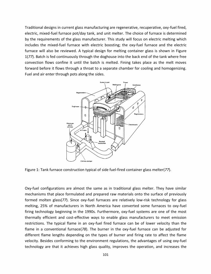
101
Traditional designs in current glass manufacturing are regenerative, recuperative, oxy-fuel fired,
electric, mixed-fuel furnace pot/day tank, and unit melter. The choice of furnace is determined
by the requirements of the glass manufacturer. This study will focus on electric melting which
includes the mixed-fuel furnace with electric boosting; the oxy-fuel furnace and the electric
furnace will also be reviewed. A typical design for melting container glass is shown in Figure
1(77). Batch is fed continuously through the doghouse into the back end of the tank where free
convection flows confine it until the batch is melted. Fining takes place as the melt moves
forward before it flows through a throat to a separate chamber for cooling and homogenizing.
Fuel and air enter through pots along the sides.
Figure 1: Tank furnace construction typical of side fuel-fired container glass melter(77).
Oxy-fuel configurations are almost the same as in traditional glass melter. They have similar
mechanisms that place formulated and prepared raw materials onto the surface of previously
formed molten glass(77). Since oxy-fuel furnaces are relatively low-risk technology for glass
melting, 25% of manufacturers in North America have converted some furnaces to oxy-fuel
firing technology beginning in the 1990s. Furthermore, oxy-fuel systems are one of the most
thermally efficient and cost-effective ways to enable glass manufacturers to meet emission
restrictions. The typical flame in an oxy-fuel fired furnace can be of lower velocity than the
flame in a conventional furnace(78). The burner in the oxy-fuel furnace can be adjusted for
different flame lengths depending on the types of burner and firing rate to affect the flame
velocity. Besides conforming to the environment regulations, the advantages of using oxy-fuel
technology are that it achieves high glass quality, improves the operation, and increases the

102
production. Its disadvantages are its corrosion problems for the superstructure refractory,
depending on the glass composition, furnace design, and operating practices.
All melters must limit forward mixing of material undergoing the batch melting, fining, and
homogenizing steps of melting. Moreover, glass melters are also heated by combustion of fuels
and direct electric heating. In general, electric melting produces a very homogenous, high-
quality glass, because the emissions are reduced and thermal efficiency is very high in an
electric furnace. However, this process is limited by its operating cost and technical
considerations, which are explained in detail later in this report.
Electrically boosted fuel-fired melters and all-electric cold-top melters use direct electric
heating. In the case of the electrically boosted fuel-fired tank furnace, 10 to 30% of the total
energy input comes from the electrodes immersed in the melting end. Electric boosting gives
better control of convection currents, because it provides better control than flames. It may
lower the melt surface temperature and gas flow rate to reduce emission. However, all-electric
cold-top melters are totally heated by the electrodes immersed into the glasses. The melt
surface is completely covered by a floating blanket of batch. All-electric melters are often
deeper than fuel-fired melters and maybe circular or rectangular. A typical circular design for a
large furnace is shown in Figure 2(79). There is only a slight difference between the
conventional large furnace method and all-electric melters. Instead of a crown with heaters on
top of the large furnace, a cold and flat top is created by covering the glass melt with cold feed.
Since there is no combustion process, there is no heat loss from flue gases in the furnace.
However, the heat loss from the electrodes has to be taken under consideration. During the
heating process, there are insulated holes inside the electrodes, so the electrodes can be
cooled by the water. The heat loss due to the water-cooling depends on the thickness of the
electrodes. To facilitate heat transfer and aid the refining process, the electrodes are developed
to improve the convective currents in the furnace. This method also increases productivity and
furnace capacity, improves glass quality, and minimizes air emissions.

103
Fig. 2: Vertical section view of a circular all-electric tank furnace(79).
3.2 Conventional Combustion
The conventional method of providing heat to melt glass is to burn fossil gas and air above a
batch of continuously fed batch material and to withdraw the molten glass continuously from
the furnace(2). To provide the desired flame temperature, air has to be always preheated. The
fuel gas is injected into the furnace by the burner and is then mixed with the preheated air. Due
to the high temperatures, the mixture of the fuel gas and oxygen in the air will ignite. The
reaction produces the energy which is used for the glass forming reaction and the heating of
the fuel gas, air, reaction gases, and feed. The fuel oil can also be used for the combustion
process(2). The fuel oil needs to be heated to reduce its viscosity in order to be injected into the
furnace as the liquid. The advantage of fuel oil over fuel gas is the higher energy amount per
volume and the higher carbon/hydrogen ratio of oil. The higher ratio allows lower flame
temperatures and results in lower emissions. Combined oil combustion is about 5% more
energy efficient than gas combustion. The disadvantage is the higher amount of polluting
compounds and heavy metals in oil which causes unwanted emissions and corrosion.
The oxy-fuel combustion method uses oxygen instead of air for the combustion of gas. Since air
contains 79% nitrogen and nitrogen is needed to be heated in the furnace, the energy losses by
these inert gases can be limited by the use of pure oxygen instead of air for combustion. The
flame reaches higher temperatures with oxygen combustion and the residence time of oxygen
combustion in the combustion chamber is longer than with the conventional air-fired method.
So, in case of oxygen firing, the gases have more time to reach a thermal equilibrium with their
surroundings(80). This better heat transfer means not only less energy consumption, but also
less oxygen use.

104
Three intermediate forms are available: oxygen boosting, oxygen lancing, and oxygen
enrichment(80). Figure 3(80) shows the scheme of oxygen boosting; it uses oxy-fuel burners
within the air-fuel mixture to increase production, quality, and efficiency. Extra fuel is
combusted with oxygen to get higher temperatures which helps to increase the glass pull rate
on the furnace. This technique uses conventional combustion as the main combustion
technique. Oxygen lancing is shown in Figure 4(80). It is the most common way to use oxygen as
a supplement to combustion to raise the production capacity(80). The injection of oxygen
beside, beneath or through air-fuel flames causes glass melting furnaces to reach a higher pull
rate, greater level of fuel efficiency, and better glass quality. In the case of oxygen enrichment
which is shown in Figure 5(80),oxygen is injected into the main combustion air header well
ahead of the point where the burner enters the furnace(80). It is desirable to use the oxygen to
enhance the entire combustion process in a consistent manner, so this pre-mix of oxygen is
most common in the melting furnace design.
Figure 3: Oxygen boosting(80).
Figure 4: Oxygen lancing(80).
Figure 5: Oxygen enrichment(80).

105
The comparison of the oxygen boosting, lancing, and enrichment methods has been studied by
Beerkens(81). The flame temperature of oxygen enrichment is higher than that of the oxygen
boosting method. The oil flame has the lowest flame temperature. The oxygen/gas flame has a
lower emission coefficient because of less formation of soot. However this effect is
compensated by the higher CO2 and H2O concentrations. Calculations for the heat transfer of
three flames then result the oxygen/gas has the highest heat flux and lowest flame area.
3.3 Electric Heating
Electric glass melting furnaces were not considered as replacements of traditional fossil fuel-
fired melters until the 1980s when the larger capacity electric furnaces were invented. Electric
melting is commonly used for homogenous and high-quality glass, such as lead crystal and opal
glass which is potentially volatile and polluting. Electric heating can be achieved by applying the
electrodes into the molten glass and there are two options for electrode placements, direct
heating and indirect heating. For direct heating, the electrodes are placed in the furnace in the
glass melt. The second option is the placement of the electrodes outside the glass tank, which is
called indirect heating. Electric boosting uses the direct heating method, which is the process of
installing the heating electrodes with conventional burners or radiant tube burners. For pure
electric heating, the glass is only heated by electrodes. However, melting of container glass in
all-electric heating furnaces is not used in commercial applications because it is too expensive
at this moment.
Electric boosting is the add-on technique to improve the efficiency and to more effectively
control the temperature. This process was patented first in the United States in 1934(5). This
did not start to come into general use until 1952. The rod electrode system is applied in the
glass furnace while it is hot and operating, without interruption of the process. The electric
booster is made to increase the maximum tonnage output of the furnace. Unlike the
conventional firing system, electric boosting increases the furnace output by the electric heat
liberated within the glass itself instead of by increasing the temperature of the glass
surroundings. In this way, the glass batch can reach a higher temperature without changing the
superstructure temperature to reduce the destruction of the refractory in the lower structure
and to lengthen campaign life. Many electric boosting systems can also reduce the intensity of
the fire. Another objective of electric boosting is to improve the glass quality. The electrodes
have the ability to create local turbulence in the glass in their immediate vicinity. In such action,
the glasses in the tank are mixed so that the bubbles are diminished(6). Electric boosting heat

106
intended to increase output and improve the quality of glass can be achieved in this charging
chamber.
All-electric melting is the best method for melting fluoride, phosphate, borosilicate and similar
glasses(82). In the normal fuel-fired furnace, the volatile materials are really easily to sweep
through the flue system, resulting in a loss of molten glass, and the glass quantity loss is
detrimental to people’s health. Another disadvantage of the normal fuel-fried method is the
different glass forming composition between the surface layer and middle batch, thus
contributing to a non-homogeneous final product. During all-electric melting(6), the heat is
produced below the batch blanket. Vapors will ascend and be condensed by the cold-top. The
amount of such condensed materials builds to a constant concentration in the batch layer. One
of the important factors for all-electric melting is that precise control of glass composition is
possible. In the all-electric melting process, problems of heat penetration in melting colored
glass are reduced when contrasted with the conventional melting methods. All-electric melting
keeps the temperature constant by producing a reasonably uniform electric current throughout
the entire volume of the glass. It is true that small all-electric furnaces are not as efficient
thermally as large all-electric furnaces, in the same way that small fuel-fired furnaces are not as
efficient as large fuel-fired furnaces(6).
Choice of melting technique depends on the capacity needed, the glass formulation, and
environmental performance. The advantages of electric heating are very low direct emissions,
potentially increased melting rate per m2 of furnace area, improved direct energy efficiency,
lower raw material costs, better glass quality, more homogeneous glass, and potentially a more
simple operation. But disadvantages of electric heating are high operating cost and non-viability
for very large-scale glass production.
4. Electrodes in Electric Heating
4.1 Role of Electrodes
Electrodes used in the electric heating furnace are of great importance in glass melting
technology. Electrodes serve to feed alternating electric current into the glass melts. Because
electrodes have electric conductivity and glass melt has ionic conductivity, the resistance of
glass melts causes Joule’s heating in the melt. It is necessary that electrodes are sufficiently
heat-resistant to withstand high temperatures in the furnace. In addition to high temperature,
one of the problems with the electrodes is that electrical charge may also lead to corrosion or

107
reduction of the electrode, thereby causing an accelerated attack on the electrode material19.
Furthermore, the corrosion of the electrodes can also discolor and contaminate the glass melt.
When a glass melt is heated electrically, many different aspects can be considered. The design
of the furnace, the electrode materials used, electrode types, and the arrangement of the
electrodes are important considerations.
4.2 Electrode Materials
Electrodes can be metallic, graphite, or other conductive material with high temperature
resistance. With metal electrodes, where the electrode is wetted by the molten glass, the
resistance is relatively low, which is an important advantage of the metal electrode. The surface
current density of the current passing from the electrode into the molten glass can be up to 3
A/cm2(10). But the main disadvantage of the metal electrodes is their high density. In an instance
of sudden electrode fracture, it becomes difficult to retrieve the electrode from the furnace.
For metal electrodes, pure metals or alloys, such as pure iron, tungsten, molybdenum, tantalum,
niobium, or nickel-chromium alloys and nickel-chromium-molybdenum alloys, can also be
employed with different furnace temperatures(10). Metal electrodes are normally used in the
form of rods or plates in solid state. And pure molybdenum is the most frequently employed
metal for rod or plate electrodes and will be discussed in detail.
Graphite electrodes were introduced by Borel(82)and have significant advantages. The density
is lower than the density of the molten glass. Without sinking in the molten glass like a metal
electrode, it is easy to retrieve the broken piece from the furnace. Graphite electrodes have
long life because of their high mechanical strength, especially when hot. Graphite electrodes
are less costly than metal electrodes. However, the disadvantage of graphite electrodes is that
they are not wetted very well by glass and thus have a greater contact resistance, which
reduces the surface current density. Because the current density must be kept low, the
diameter of the electrodes must be fairly large. So graphite electrodes are being used
successfully at low current densities. Furthermore, graphite electrodes cannot be used for
borosilicate glasses, colored glasses, or lead crystal glasses. Because graphite electrodes are
attacked by these oxidized glasses, reduction of these metallic oxides occurs in the molten glass.
The reduced metal is deposited on the graphite electrode.
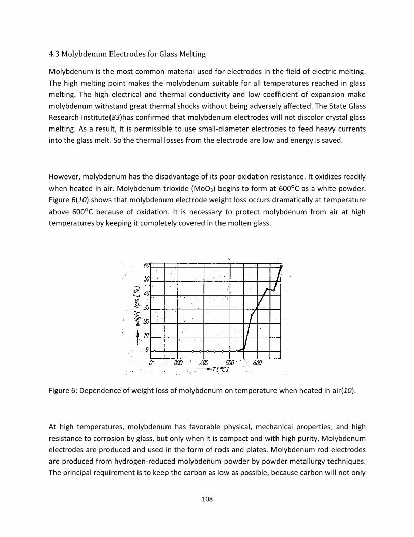
108
4.3 Molybdenum Electrodes for Glass Melting
Molybdenum is the most common material used for electrodes in the field of electric melting.
The high melting point makes the molybdenum suitable for all temperatures reached in glass
melting. The high electrical and thermal conductivity and low coefficient of expansion make
molybdenum withstand great thermal shocks without being adversely affected. The State Glass
Research Institute(83)has confirmed that molybdenum electrodes will not discolor crystal glass
melting. As a result, it is permissible to use small-diameter electrodes to feed heavy currents
into the glass melt. So the thermal losses from the electrode are low and energy is saved.
However, molybdenum has the disadvantage of its poor oxidation resistance. It oxidizes readily
when heated in air. Molybdenum trioxide (MoO3) begins to form at 600°C as a white powder.
Figure 6(10) shows that molybdenum electrode weight loss occurs dramatically at temperature
above 600°C because of oxidation. It is necessary to protect molybdenum from air at high
temperatures by keeping it completely covered in the molten glass.
Figure 6: Dependence of weight loss of molybdenum on temperature when heated in air(10).
At high temperatures, molybdenum has favorable physical, mechanical properties, and high
resistance to corrosion by glass, but only when it is compact and with high purity. Molybdenum
electrodes are produced and used in the form of rods and plates. Molybdenum rod electrodes
are produced from hydrogen-reduced molybdenum powder by powder metallurgy techniques.
The principal requirement is to keep the carbon as low as possible, because carbon will not only

109
cause bubble formation in the glass, but will also impair the mechanical properties of
molybdenum. Carbon contents in the electrodes will form bubbles for a short period at high
temperatures. If the electrode has high carbon content, bubbles will continue to form for
several weeks.
Table 1(10)shows the important physical properties of molybdenum. It has excellent electrical
and thermal conductivity, only slightly less than tungsten, but has the advantage of having half
the density of tungsten. Molybdenum has also one of the lowest linear expansion coefficients
of any metal in experiments conducted from room temperature to above 1000°C, which makes
its use important in glass-to-metal seals and in electronic components. Furthermore, its thermal
conductivity and linear expansion coefficient are quite close to silicon, an element which also
has relatively good electrical conductivity. The mechanical properties of molybdenum are
greatly influenced by the fabrication method. The tensile strength decreases with the increasing
temperature and reduction is considerable at high temperatures, as shown in Figure 7(10).
Curve B in Figure 8(10)also shows the dramatic ductility increase of the molybdenum after
short-term annealing was applied to the electrode at temperatures from 900 to 1250°C.
Molybdenum electrodes can be used without difficulty in melting glasses not containing PbO,
As2O3 or Sb2O3. The relationship between the electrode corrosion process and the refining
agents, such as arsenic and antimony, is also mentioned in section 2. The detailed mechanism
of the molybdenum corrosion will be taken under consideration in the next section.
Table 1: Some important properties of molybdenum at various temperatures(10).

110
Figure 7: Increasing strength of molybdenum at increasing temperature(10).
Figure 8: Strength and ductility of molybdenum vs. annealing temperature(10).
A, Strength; B, Ductility

111
5. Failure Mechanisms of Molybdenum Electrodes
5.1 Internal Factors for Molybdenum Corrosion
Molybdenum is commonly used as an electrode material for electric glass melting. However,
the material cost for Mo is high. It is, therefore, necessary to keep its consumption and,
consequently, its corrosion by glass melts as low as possible. In addition, the products of
corrosion affect the color of glass especially when melting crystal glass. The reasons of metal
corrosion by glass melt in general are the successive and coupled electrode reactions, the
course of which depends on several internal corrosion factors.
Stanek(12) introduced the idea that the internal corrosion factors depend mainly on
molybdenum itself, i.e.; its chemical purity, structure, character of its surface, presence of its
primary protective layer, mechanical stress, and deformation of the material. To maintain the
chemical purity of molybdenum, it is essential to keep the carbon concentration as low as
possible. The electrodes with carbon contents of at most 50 ppm cause bubble formation for a
limited period(10); e.g.; in borosilicate glasses it occurs for several hours. If the carbon content
of the electrode is higher, bubbles will continue to form for several weeks. The carbon content
of 50 ppm is also critical from the point of view of corrosion which rises rapidly in the range of
60-70 ppm of carbon content(10).
5.2 Outer Factors for Molybdenum Corrosion
5.2.1 Molybdenum Corrosion Behavior in Different Glass Melts
Besides internal factors, outer factors influencing the corrosion of electrodes are the chemical
character of corrosive environment, the kind of anions and cations, temperature, and contact
with other metals, electric current and current frequency. Electric melting of some glasses,
especially lead oxide glasses is limited by heavy corrosion of molybdenum electrodes being
connected with the contamination of glass melt(74). The extent of molybdenum corrosion is
drastically increased by the presence of lead oxide and cations of arsenic or antimony. In
addition, the presence of other polyvalent ions, such as Fe3+, Co2+, or Ni2+ can also increase the
corrosion rate. They are so-called depolarizers2, defining the corrosiveness of the glass melt.
Matej(11) investigated the relationship between the molybdenum corrosion and lead
precipitation rates together with the overall electrode current by using the potential of the

112
molybdenum electrode in three glass melts. Two of the melts contained 24 wt% lead oxide, one
of them also containing a little arsenic oxide, and the third glass melt was free from lead oxide.
The corrosion rate of molybdenum expressed as the rate of precipitation of lead was
proportional to the sum of the molar concentration of both alkalis. The result of Stanek’s study
is shown in Fig. 9(12). The conclusion of this study shows that molybdenum is corroded on the
account of the lead oxide. The rate of corrosion is determined by the intensity of the partial
anodic current. At a corrosion potential, layers of reaction products containing molybdenum,
lead, potassium and small amounts of sodium occur on the surface of molybdenum electrodes
in lead glass melts. The molybdenum vacancy of 3 corresponds best to the oxygen content in
the products. When the potential is raised by 400 mV, the layers only contain molybdenum and
oxygen (MoO3).
Figure 9: Dependence of the rate of electrode processes on the polarizing curve potential(12).
In the study by Yamamoto(13), he investigated the influence of the antimony concentration,
which is used as a fining agent, and the temperature on the corrosion of electrodes in the TV
glass melt. A schematic drawing of the corrosion mechanism is demonstrated in Figure 10 (a)
and (b)(13). Since the normal electrode potential of molybdenum is much lower than that of
antimony, molybdenum electrodes can be easily corroded in the glass melt containing
antimony ions. The metallic antimony particles were observed around the electrodes after
dipping in the glass melt. Antimony ions and the dissolved molybdenum ions were detected in
the molybdenum/glass interface. Yamamoto concluded that the corrosion rate of molybdenum
electrodes was proportional to the antimony concentration in the glass melt. He clarified that

113
the dominant factor of corrosion process was the redox reaction of the molybdenum electrodes
with antimony ions in the glass melt.
Figure 10: Corrosion mechanism of molybdenum electrodes in glass melts (a) without AC supply
or (b) with AC supply(13).
Vanmoortel(9) studied the influence of iron, nickel, and cobalt on the corrosion behavior of
molybdenum electrodes in the molten glass by using electrochemical techniques. The corrosion
potential of the metal was applied to determine the surface reactivity of the molybdenum
electrodes. The stable corrosion potential values for the various melt compositions are given in
Table 2(20). In each series of measurements, a clear tendency can be observed. The corrosion
potential increases with increasing cation concentration. This trend can also be explained by a
theoretical current-potential curve of a corrosion system in Figure 9(12). In the case of iron,
nickel or cobalt acting as an oxidizing agent in the corrosion reaction of molybdenum,
increasing concentration of these metal ions results in a raised cathodic current, depicted as
the dashed curve in Figure 9(12). The dashed curve shows that the corrosion potential value
shifts to a more positive value, resulting in a higher corrosion rate of the molybdenum
electrodes. Results of mass loss experiments are shown in Table 3(9), which indicates that the
corrosion rate of molybdenum increases with higher concentration of iron, nickel, and cobalt
oxides. Moreover, nickel oxide is shown to be the most aggressive metal ion and iron oxide the
least aggressive metal ion. Therefore, it is possible to identify iron, nickel and cobalt oxides as
reduction partners in the corrosion of molybdenum by using corrosion potential measurements.

114
Table2: Average corrosion potential values(9).
Table3: Mass loss data of molybdenum in different glass melts(9).
The corrosion of molybdenum electrodes in an aluminosilicate glass melt was studied by
Russel(22). With the help of electrochemical methods, a layer of molybdenum oxide is found on
the electrode in contact with the glass melt. The layer partially dissolves in the glass melt and
evaporates into the furnace atmosphere in the end. In all corrosion experiments, both
molybdenum layers and metallic particles can be observed by energy dispersive X-ray
spectroscopy (EDX). The thickness of this surface layer is strongly influenced by the
experimental conditions, increasing with the corrosion time (in Figure 10)(22). As shown in
Figure 10, the oxide layer thickness is surprisingly greater at lower temperature. The oxide layer
is controlled by the solubility of molybdenum oxide in the glass melt and by dissolution kinetics.
The rate of dissolution increases with the increasing temperature, which is the same process
the corrosion rate follows. If the dissolution rate increases more strongly than the corrosion
rate does with increasing temperature, the thickness of the layer will decrease with increasing

115
temperature. Thus, the thickness of the surface cannot be used as a measure of the corrosion
rate. Russel assumed that dissolution of the oxide layer was the step to determine the rate of
the corrosion process.
Figure 10: Thickness, d, of the molybdenum oxide surface layer as a function of the corrosion
time, t, in an aluminosilicate glass melt(22).
5.2.2 Effect of Alternating Current on Molybdenum Corrosion
Alternating current is also one of the outer factors continually affecting the heating electrodes
in electric glass melting. It has been proved that the corrosion of molybdenum in glass melt is
influenced not only by the power loading but also by the surface current density. The amount
of corroded molybdenum and precipitated lead are approximately equivalent within broad
limits of the alternating current loading. Devay(12)indicated the reason for accelerated
corrosion is the increase of mean value of the anodic current (the corrosion current) as shown
in Figure 9 by dashed lines. The mean value of the cathodic current which is a measure of the
depolarization reactions rate tends to be equal to the anodic current increase. The corrosion
rate increases with growing alternating current density but decreases with increasing frequency,
as has been confirmed by additional studies(11). The dependence of corrosion rates on current
density or frequency also affects the mean electrode potential. The corrosion of molybdenum
electrodes increases with increasing current density (shown in Figure 11). Matej’s study(11)also
elaborated that alternating current can affect the corrosion and lead precipitation rate in
various glasses melts in both directions. The accelerating effect always manifests itself in
parallel with a shift of the mean electrode potential towards the more negative values and vice
versa.

116
The study of dependence of molybdenum electrode corrosion in glass melt on frequency has
shown that in a region of low frequencies, the corrosion as well as the amount of decomposed
depolarizer may decrease with decreasing frequency. In Figure 12(12), the shape of curve
presents a minimum of corrosion at some optimal low frequency. Below this optimal frequency,
there is the minimal corrosion. Besides frequency, the dependence of the amount of
decomposed depolarizer and of the molybdenum corrosion also depends on the current
density and the temperature of the electrode surface. Therefore the corrosion rate may be in a
broad range of conditions a function of the ratio between current density and frequency of the
alternation current. The corrosion rate tends to be on the increase again below the optimum
frequency. It brings out a convection flow in the glass melt. The diffusion processes will be
accelerated and the protective layer of the anodic products may be destroyed. This accounts
for the corrosion rate at the lowest frequencies being reaccelerated. The fact that there exists
an optimal low frequency region where the corrosion rate decreases, maybe applied for the
protection of molybdenum electrodes against corrosion.
Figure 11: Dependence of corrosion rate of molybdenum electrode on current density in the TV
glass (a) without AC supple, (b) with current density of 0.53 A/cm2(13).
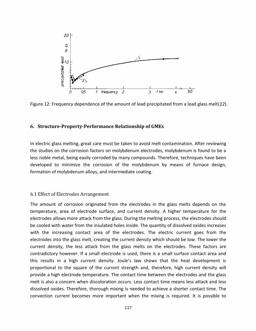
117
Figure 12: Frequency dependence of the amount of lead precipitated from a lead glass melt(12).
6. Structure-Property-Performance Relationship of GMEs
In electric glass melting, great care must be taken to avoid melt contamination. After reviewing
the studies on the corrosion factors on molybdenum electrodes, molybdenum is found to be a
less noble metal, being easily corroded by many compounds. Therefore, techniques have been
developed to minimize the corrosion of the molybdenum by means of furnace design,
formation of molybdenum alloys, and intermediate coating.
6.1 Effect of Electrodes Arrangement
The amount of corrosion originated from the electrodes in the glass melts depends on the
temperature, area of electrode surface, and current density. A higher temperature for the
electrodes allows more attack from the glass. During the melting process, the electrodes should
be cooled with water from the insulated holes inside. The quantity of dissolved oxides increases
with the increasing contact area of the electrodes. The electric current goes from the
electrodes into the glass melt, creating the current density which should be low. The lower the
current density, the less attack from the glass melts on the electrodes. These factors are
contradictory however. If a small electrode is used, there is a small surface contact area and
this results in a high current density. Joule’s law shows that the heat development is
proportional to the square of the current strength and, therefore, high current density will
provide a high electrode temperature. The contact time between the electrodes and the glass
melt is also a concern when discoloration occurs. Less contact time means less attack and less
dissolved oxides. Therefore, thorough mixing is needed to achieve a shorter contact time. The
convection current becomes more important when the mixing is required. It is possible to

118
influence the intensity of the convection current of the glass melt by suitably arranging the
electrodes.
Kasa(71) has shown a 3-D mathematical modeling that different arrangements of electrodes in
an all-electric melting furnace influence the power density in the glass melt. The bottom, top,
and plate electrodes as shown in Figure 13 have been arranged in the model furnace. The
results from the model indicated that there is a very narrow relationship between the
distribution of power density in glass melt and the temperature. Figure 14 shows the
distribution of the power density and temperatures in horizontal gradients above the
electrodes. The plotted and calculated data lines both reveal marked peaks in the electrode
zones for all electrode arrangements. Therefore, it ascertains the intimate relationship between
the power density distribution and the temperature. Thus, the intensity of the glass convection
flow can be influenced by the electrode arrangements in the tank. The power density
distribution in the central vertical gradients is shown in Figure 15. Figure 16 shows the
maximum power density on the electrode length and distance of plate electrodes from the tank
bottom. For rod electrodes, the power density decreases as the length of electrodes increase.
This phenomenon occurs because the glass volume in the close vicinity of electrodes maybe
released and increases with the increasing electrode length(71). A totally opposite situation was
found in the case of plate electrodes: the amount of energy released in the center of the tank
grows with the increasing distance between the electrodes and the tank bottom. The results
showed the power density distribution can be influenced substantially by electrode
arrangement in the furnace as well as by the type and dimensions of the electrodes, a finding
that is in perfect agreement with Curran’s study(70). Curran investigated the distribution of
energy released in the glass melt using a 2-D mathematical model. Both Curran and Kasa
concluded the power density distribution generated by rod electrodes exhibits highly localized
characteristics, resulting in a temperature field and circulation pattern that can be widely
influenced by the electrode configuration.

119
Figure 13: The configurations of the investigated furnaces equipped with the bottom, top and
plate electrodes(71).
Figure 14: Power density and temperature distribution in horizontal gradients(71). (Point-
bottom electrodes, square-top electrodes, triangle-plate electrodes, full symbols-power density,
empty symbols-temperature)
Figure 15: Power density distribution in the central vertical gradient(71).
Value A means the length of bottom and top electrodes or distance of plate electrodes from the
tank bottom (point- bottom electrodes, square-top electrodes, triangle- plate electrodes).

120
Figure 16: Dependence of the depth in the central vertical gradient with the maximum power
density on the electrode length or the distance of plate electrodes from the tank bottom(71).
Value A means the length of bottom and top electrodes or the distance of plate electrodes from
the tank bottom (point-bottom electrodes, square-top electrodes, triangle-plate electrodes)
6.2 Effect of Second-Phase Particles
Since molybdenum electrodes that come into contact with glass melts are exposed to strong
corrosive attack, they are not usable for the majority of highly corrosive glass melts. High
mechanical strength or good creep characteristics at high temperature are expected primarily
from molybdenum electrodes because they function as high temperature materials. To further
improve these properties, the formation of molybdenum alloys will be the approach based on
Leichtfried’s study(84).
The desired results to limit corrosion resistance of the materials in contact with glass melts are
less removal of material surface and lower intercrystalline corrosion(84). Intercrystalline
corrosion, known as intergranular corrosion, is the localized attack occurring along the crystal
boundaries of the material. The glass composition in the glass melt is reduced by molybdenum
and will form relatively low-melting compounds with molybdenum, and thus the compounds
spread out along the crystal boundaries by diffusion, resulting in weakening of the electrodes.
Intercrystalline corrosion value is smaller than the surface removal of the electrodes. This is
important to evaluate the overall corrosion characteristics. Sometimes the danger of cracking

121
of the molybdenum electrode would be expected to be higher than on the basis of a reduction
in diameter.
U.S. Patent No. 6090227(84)describes how the satisfactory corrosion protection is achieved by
supplementary additions of ZrO2 with Si or B in melts with polyvalent elements which cause
strong grain boundary corrosion. Besides the strongly reduced surface removal, grain boundary
corrosion attack is above all significantly reduced by the supplementary addition of 5 vol% ZrO2
with 0.03 wt% Si or B(84). The latter elements preferentially accumulate at the grain
boundaries of the Mo electrodes. Leichtfried also compared different supplementary additions
doped with pure molybdenum electrode (in Table 4). The surface removal and intercrystalline
corrosion are indicated in units of mm/year. He concluded the optimum Si and/or B additions
will be at approximately 0.03 wt% in glass melts. The corrosion rate increases again at higher
contents, which can be connected with an increase in the diffusion rate. With a higher addition
rate of Si and/or B, the mechanical process-ability of the electrodes is also reduced, since the
cost of the mechanical shaping will increase. Moreover, the metals Pd, Pt, Ir and Ru in
quantities of 0.05-3 wt% act in the same way as Si and B(84).
Table 4: A comparison of results from examples 1-5(84).
Example
#
Composition Surface removal Depth of corrosion
1 Pure Mo 17 mm/year 20 mm/year
2 Mo with 3 vol% ZrO2 11 mm/year 19 mm/year
2 Mo with 5 vol% ZrO2 8 mm/year 16 mm/year
2 Mo with 7 vol% ZrO2 8.5 mm/year 16.5 mm/year
3 Mo with 5 vol% ZrO2, 0.03wt% Si 5.5 mm/year 6 mm/year
4 Mo with 5 vol% ZrO2, 0.03wt% B 7 mm/year 11.5 mm/year
5 Mo with 2 vol% ZrO2, 0.03wt% Si 12.5 mm/year 11.5 mm/year
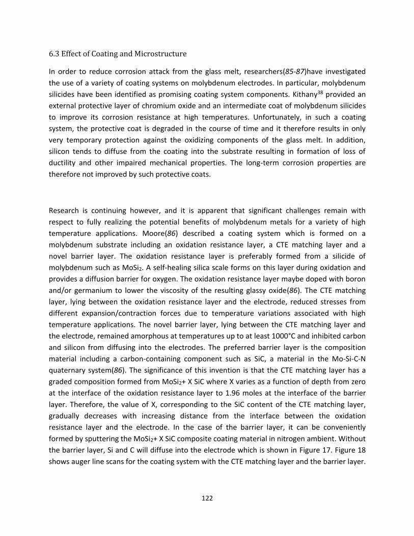
122
6.3 Effect of Coating and Microstructure
In order to reduce corrosion attack from the glass melt, researchers(85-87)have investigated
the use of a variety of coating systems on molybdenum electrodes. In particular, molybdenum
silicides have been identified as promising coating system components. Kithany38 provided an
external protective layer of chromium oxide and an intermediate coat of molybdenum silicides
to improve its corrosion resistance at high temperatures. Unfortunately, in such a coating
system, the protective coat is degraded in the course of time and it therefore results in only
very temporary protection against the oxidizing components of the glass melt. In addition,
silicon tends to diffuse from the coating into the substrate resulting in formation of loss of
ductility and other impaired mechanical properties. The long-term corrosion properties are
therefore not improved by such protective coats.
Research is continuing however, and it is apparent that significant challenges remain with
respect to fully realizing the potential benefits of molybdenum metals for a variety of high
temperature applications. Moore(86) described a coating system which is formed on a
molybdenum substrate including an oxidation resistance layer, a CTE matching layer and a
novel barrier layer. The oxidation resistance layer is preferably formed from a silicide of
molybdenum such as MoSi2. A self-healing silica scale forms on this layer during oxidation and
provides a diffusion barrier for oxygen. The oxidation resistance layer maybe doped with boron
and/or germanium to lower the viscosity of the resulting glassy oxide(86). The CTE matching
layer, lying between the oxidation resistance layer and the electrode, reduced stresses from
different expansion/contraction forces due to temperature variations associated with high
temperature applications. The novel barrier layer, lying between the CTE matching layer and
the electrode, remained amorphous at temperatures up to at least 1000°C and inhibited carbon
and silicon from diffusing into the electrodes. The preferred barrier layer is the composition
material including a carbon-containing component such as SiC, a material in the Mo-Si-C-N
quaternary system(86). The significance of this invention is that the CTE matching layer has a
graded composition formed from MoSi2+ X SiC where X varies as a function of depth from zero
at the interface of the oxidation resistance layer to 1.96 moles at the interface of the barrier
layer. Therefore, the value of X, corresponding to the SiC content of the CTE matching layer,
gradually decreases with increasing distance from the interface between the oxidation
resistance layer and the electrode. In the case of the barrier layer, it can be conveniently
formed by sputtering the MoSi2+ X SiC composite coating material in nitrogen ambient. Without
the barrier layer, Si and C will diffuse into the electrode which is shown in Figure 17. Figure 18
shows auger line scans for the coating system with the CTE matching layer and the barrier layer.
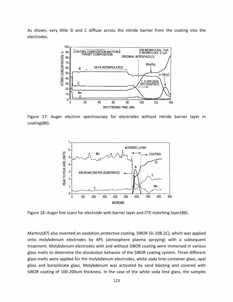
123
As shown, very little Si and C diffuse across the nitride barrier from the coating into the
electrodes.
Figure 17: Auger electron spectroscopy for electrodes without nitride barrier layer in
coating(86).
Figure 18: Auger line scans for electrode with barrier layer and CTE matching layer(86).
Martinz(87) also invented an oxidation protective coating, SIBOR (Si-10B-2C), which was applied
onto molybdenum electrodes by APS (atmosphere plasma spraying) with a subsequent
treatment. Molybdenum electrodes with and without SIBOR coating were immersed in various
glass melts to determine the dissolution behavior of the SIBOR coating system. Three different
glass melts were applied for the molybdenum electrodes, white soda lime container glass, opal
glass and borosilicate glass. Molybdenum was activated by sand blasting and covered with
SIBOR coating of 100-200um thickness. In the case of the white soda lime glass, the samples

124
were heated up to 1300°C. After each 24h step, the samples were taken out of the crucible,
drawn off from the holder and dropped into water except those destined for microanalysis40.
The samples destined for microanalysis cooled freely on air. Figures 19 and 20show the cross-
sections of the metal-glass interface of the samples. As shown, the coating for the dissolution
test is not yet finished after 192 and 96 hours in Figure 19. EDX analysis will be used to prove
the composition of the remaining coating system. In the case of the molybdenum without
coating, only small voids in the dense material are visible after 192 hours (Figure 20). For opal
glass, only SIBOR-coated molybdenum samples were used to be compared with soda lime glass.
As shown in Figure 21 and 22, SIBOR on molybdenum was not dissolved within one week. The
remaining coating is Si-free and B can be found in the diffusion zone below the molybdenum
electrode. Compared to soda lime glass, the coating system dissolved greatly in opal glass
because of its high alkali fluoride content. For the borosilicate glass dissolution experiments,
SIBOR was found slowly reacted in Figure 23. After one week, the outside of the coating had
lost the Si, but inside zones remained unchanged. This is caused by the high temperature of the
glass which will enhances the formation of thick and dense diffusion zones. In addition, the low
content of alkali metal of the borosilicate glass is the reason for a weaker reaction with Si.
Molybdenum electrodes with SIBOR coating system is most easily destroyed by the alkali and
fluoride-rich opal glass; less easily destroyed is the soda lime glass with a relatively lower
reactivity. Borosilicate glass with lowest alkali content reacts most slowly with the SIBOR
coating system.
Figure 19: Cross-section of electrodes with SIBOR after 24 hours (left) and 8X24 hours
(right)(87).

125
Figure 20: Cross-section of electrodes without SIBOR after 24 hours (left) and 8X24 hours
(right)(87).
Figure 21: Cross-section of the metal-glass interface of sample after 24 hours (left) and 72 hours
(right) in opal glass(87).
Figure 22: Cross-section of the metal-glass interface of sample after 168 hours in opal glass(87).

126
Figure 23: Cross-section of the metal-glass interface of sample after 24 hours (left) and 168
hours (right) in borosilicate glass(87).
7. Technology Gaps and Opportunities
Nowadays all types of glasses are melted electrically, from soda lime to lead glasses,
borosilicate, fiber glasses, and sodium silicates. Tonnages now being pulled from electric
furnaces vary from between 50 pounds per hour to 140 tons per day. The art of electric
boosting has played an important part in the evolution of full electric melting. For companies
which are involved in electric boosting, the transition of all-electric melting is becoming easier.
The literature also shows an even greater demand for electric boosting, not for the increase in
tonnage for which it has been historically known, but as a means to use less fossil fuel and to
reduce particulate emissions from stacks. Therefore, a thorough mastery of investigation of
electrodes will demand a great deal of research and development.
Since the corrosion characteristics of molybdenum are unsatisfactory for strongly corrosive
types of glass melts, the target for the electrodes is to improve the corrosion resistance of the
molybdenum electrodes at high usage temperatures. Until now, no economically and
technically satisfactory procedures are known which prevent the chemical contamination of
highly corrosive glass melts. Several patents describe how molybdenum electrodes have a
silicon addition to increase oxidation, corrosion resistance, and creep resistance at high usage
temperatures. But the disadvantage of this, as a consequence of the high silicon content, is that
the designed alloy is incapable of being shaped mechanically so that the majority of
molybdenum electrodes cannot be economically manufactured. Other studies focused on the
coating system for Mo electrodes. Electrodes will be covered by the coating which inhibits the
oxidation or corrosion reactions. The disadvantage, however is that the protective coat is
degraded in the course of time and it, therefore results only in very temporary protection

127
against the oxidation components in the glass melts. Another concern is that the stability of
molybdenum which is not like platinum materials is thermodynamically inexplicable. The
compatibility of molybdenum with glass melts must, therefore, be explained via the kinetics of
various simultaneously occurring reactions. However, so little is known about the kinetic
processes, affecting the usability or non-usability of molybdenum electrodes in different glass
melts and especially with significant proportions of polyvalent elements.
The future of electric melting of glass is now assured. A solution to the research problems
outlined above is no doubt of importance for the improvement of the melting process in
general as well as to electric melting in particular.
Reference: 1. G. Morey, The properties of glass. 2d edition (ACS, Reinhold, New York, 1950), vol. 77. 2. H. D. Waal, R. Beerken, NCNG Handbook of glass manufactrure. 2nd edition (ed. 2d ed, Sept.
1997). 3. C. Ross, G. Tincher, A Technical and Economic Assessment, Glass manufacturing Industry Council
with the US Department of Energy-Office of Industrial Technologies. Glass Melting Technology, (2004).
4. M. Ruth, P. Dell'Anno, An industrial ecology of the US glass industry. Resources Policy23, 109-124 (1997).
5. L. Penberthy, Current status of electric booster melting. Glass industry36, 635 (1955). 6. A. Gell, Electric glass melting furnace. Engineer201, 5237 (Jun 1956). 7. N. P. Vinogradov, V. I. Pankov, I.K.Sobolev, Electrical glass melting. Glass and Ceramics32, 693-
696 (1975). 8. J. Tallkvist, A. Oskarsson, in Handbook on the Toxicology of Metals (Fourth Edition). (2014), vol.
Volume II: Specific Metals, chap. 47, pp. 1077-1089. 9. I. Vanmoortela, J. D. Stryckerb, E. Temmermana, A. Adriaens, The influence of polyvalent metal
cations on the corrosion rate of molybdenum in molten glass. Journal of Non-Crystalline Solids353, 2179-2185 (2007).
10. J. Stanek, Glass Science and Technology 1: Electric Melting of Glass. (Elsevier, Amsterdam,New York 1977).
11. J. Matej, E. Krupkova, V. Hulinsky, The mechanism of dissolution of molybdenum in glass melt and the effect of alternating current. Ceramics46, 133 (2002).
12. J. Stanek, Electrical melting of glass. Journal of Non-Crystalline Solids84, 353-362 (1986). 13. M. Yamamoto, K. Sakai, R. Akagi, M. Sakai, H. Yamashita, T. Maekawa, Electrochemical study on
the corrosion of Molybdenum electrodes in TV glass melts containing antimony. Asahi Glass53, 25-30 (2003).
14. D. M. Dimiduk, J. H. Perepezko, Developing a Revolutionary Turbine-Engine Materials MRS Bulletin28, 639 (2003).
15. C.Holzer, C. Vichytil, G. Mori, C. Linke, paper presented at the 18th Plansee Seminar, 2013. 16. E. Abbott, Comparison of glass furnace operation with oil and natural gas. Glass Technol18, 143-
147 (1977).

128
17. Anon, Turning up the heat in all electric glass melting, Glass (London). Glass (London)78, 276 (2001).
18. J. Matej, A. Langrova, Reaction products and corrosion of molybdenum electrode in glass melt containing antimony oxides and sodium sulfate. Ceramics-Silikaty56, 280-285 (2012).
19. J. Matěj, R. Kocourová, A. Langrová, V. Čierná, The behavior of molybdenum electrode in sulphate-refined glass melt. Ceramics-Silikáty 47, 162-168 (2003).
20. M. Yamamoto, K. Sakai, R. Akagi, M. Sakai, H. Yamashita, T. Maekawa, Electrochemical Corrosion of Molybdenum Electrodes in an Aluminosilicate Glass Melt Containing Antimony. Journal of The Ceramic Society of Japan112, 179-183 (2004).
21. T. Rudolph, G. Balazs, C. Russel, G. Tomandi, Electrochemical study on the corrosion of molybdenum electrodes in lead glass melts. Glastechnische Berichte61, 177-183 (1988).
22. S. Holzwarth, C. Russel, G. Tomandi, Corrosion of molybdenum electrodes in an aluminosilicate glass melt. Glastechnische Berichte64, 195-198 (1991).
23. I. Vanmoortel, J. Strycker, E. Temmerman, A. Adriaens, Insights into the oxidation mechanism of molybdenum in molten glass. CERAMICS-SILIKATY52, 1-7 (2008).
24. C. R. Kurkjian, W. R. Prindle, Perspectives on the history of glass composition. J. Am. Ceram. Soc84, 795-813 (1998).
25. G. Balazs, C. Russel, Electrochemical studies of the corrosion of molybdenum electrodes in soda-lime glass melts. Journal of Non-Crystalline Solids105, 1-6 (1988).
26. D. M. Berczik. (1997). 27. D. M. Berczik. (1997), vol. US 5693156 A. 28. J. S. Park, R. Sakidja, J. H. Perepezko, Coating designs for oxidation control of Mo-Si-B alloys.
Scripta materialia46, 765-770 (2002). 29. K. Yoshimi, S. Nakatani, T. Suda, S. Hanada, H. Habazaki, Oxidation behavior of Mo5SiB2-based
alloy at elevated temperatures. Intermetallics10, 407-414 (2002). 30. K. Yoshimi, S. Nakatani, N. Nomura, S. Hanada, Thermal expansion, strength and oxidation
resistance of Mo/Mo5SiB2 in-situ composites at elevated temperatures. Intermetallics11, 787-794 (2003).
31. M. G. Mendiratta, T. A. Parthasarathy, D. M. Dimiduk, Oxidation behavior of αMo-Mo3Si-Mo5SiB2 (T2) three phase system. Intermetallics10, 225-232 (2002).
32. C. A. Nunes, R. Sakidja, Z. Deng, J. H. Perepezko, Liquidus projection for the Mo-rich portion of the Mo-Si-B ternary system. Intermetallics8, 327 (2000).
33. R. Sakidja, J. Werner, J. H. perepezko, paper presented at the Surface Modification Technologies: Proceedings of the 19th International Conference (ASM International), 2006.
34. R. Sakidja, J. S. Park, J. Hamann, J. H. Perepezko, Synthesis of oxidation resistant silicide coatings on Mo-Si-B alloys. Scripta materialia53, 723-728 (2005).
35. M. K. M. A. J. Thom, M. Akinc, Oxide scale formation and isothermal oxidation behavior of Mo-Si-B intermetallics at 600-1000°C. Intermetallics7, 153-162 (1999).
36. J. H. Perepezko, J. S. Park, R. Sakidja. (2009), vol. US 7560138 B2. 37. J. H. Perepezko, R. Sakidja, Oxidation Resistant Coatings for Ultrahigh Temperature Refractory
Mo-Base Alloys. Advanced engineering materials11, 892-897 (2009). 38. N. P. Bansal, R. H. Doremus, in Handbook of glass properties. (1986), pp. 607-645. 39. B. V. Cockram, R. A. Rapp, The kinetics of multilayered titanium-silicide coatings grown by the
pack cementation method. Metall. Mater. Trans.26, 777-791 (1995). 40. S. R. Levine, R. M. Caves, Thermodynamics and Kinetics of Pack Aluminide Coating Formation on
IN-100. J. Electrochem. Soc.121, 1051-1064 (1974). 41. A.Mueller, G. Wang, R. A. Rapp, E. L. Courtright, T. A. Kircher, Oxidation behavior of tungsten
and germanium-alloyed molybdenum disilicide coatings. Mater.Sci.Eng.A155, 199-207 (1992).

129
42. I. Shiota, paper presented at the TMS, Warrendale, PA, 1993. 43. T. A. Kir, E. L. Courtright, Engineering limitations of MoSi2 coatings. Mater.Sci.Eng.A155, 67-74
(1992). 44. M. K. Meyer, M.Akinc, Oxidation Behavior of Boron-Modified Mo5Si3 at 800°-1300°C. Journal of
the American Ceramic Society79, 819-1136 (1996). 45. K. Natesan, S. C. Deevi, Oxidation behavior of molybdenum silicides and their composites.
Intermetallics8, 1147-1158 (2000). 46. X. Fan, T. Ishigaki, Mo5Si3-Boron Composites Fabricated by Induction Plasma Deposition and
Their High-Temperature Oxidation Resistance. Journal of the American Ceramic Society82, 1965-1968 (1999).
47. J. H. Perepezko, R. Sakidja, Oxidation-resistant coatings for ultra-high-temperature refractory Mo-based alloys. JOM62, 13-19 (2010).
48. K. Ito, T. Murakami, K. Adachi, M. Yamaguchi, Oxidation behavior of Mo-9Si-18B alloy pack-cemented in a Si-base pack mixture. Intermetallics11, 763-772 (2003).
49. K. Ito, T. Murakami, K. Adachi, M. Yamaguchi, Evolution kinetics and microstructure of MoSi2 and Mo5Si3 surface layers on two-phase Mo-9Si-18B alloy during pack-cementation and high-temperature oxidation. Intermetallics12, 407-415 (2004).
50. T. Hayashi, K. Ito, H. Numakura, Reaction diffusion of MoSi2 and Mo5SiB2. Intermetallics13, 93-100 (2005).
51. R. Sakidja, J. H. Perepezko, S.Kim, N. Sekido, Phase stability and structural defects in high-temperature Mo-Si-B alloys. Acta Materialia56, 5223-5244 (2008).
52. J. H. Perepezko, M. H. d. S. Bassani, J. S. Park, A. S. Edelstein, R. K. Everett, Diffusional reactions in composite synthesis. Materials Science and Engineering: A195, 1-11 (1995).
53. J. L. Ham, F. P. Bens, A. J. Herzig, G. A. Timmons. (1954), vol. US 2678271 A. 54. M.Nagae, T.Yoshio, J.Takada, Y.Hiraoka, Improvement in Recrystallization Temperature and
Mechanical Properties of a Commercial TZM Alloy through Microstructure Control by Multi-Step Internal Nitriding. Materials Transactions46, 2129-2134 (2005).
55. B. V. Cockeram, The mechanical properties and fracture mechanisms of wrought low carbon arc cast (LCAC), molybdenum-0.5pct titanium-0.1pct zirconium (TZM), and oxide dispersion strengthened (ODS) molybdenum flat products. Materials Science and Engineering A418, 120-136 (2006).
56. I. G. Sharma, S. P. Chakraborty, A. K. Suri, Preparation of TZM alloy by aluminothermic smelting and its characterization. J. Alloys Compd.393, 122-128 (2005).
57. S. P. Chakraborty, S. Banerjee, G. Sanyal, V. S. Bhave, B. Paul, I. G. Sharma, A. K. Suri, Studies on the synthesis of a Mo-30 wt% W alloy by non-conventional approaches. Journal of Alloys and Compounds501, 211-217 (2010).
58. B. Paul, P. K. Limaye, R. C. Hubli, A. K. Sur, Microstructure and wear properties of silicide based coatings over Mo-30W alloy. Int. Journal of Refractory Metals and Hard Materials44, 77-83 (2014).
59. L. E. Iorio, B. P. Bewlay, M. Larsen, Analysis of AKS- and lanthana-doped molybdenum wire. Int. Journal of Refractory Metals and Hard Materials24, 306-310 (2006).
60. A. J. Mueller, R. Bianco, R. W. Buckman, Evaluation of oxide dispersion strengthened (ODS) molybdenum and molybdenum-rhenium alloys. International Journal of Refractory Metals and Hard Materials18, 205-211 (2000).
61. M. Endo, K. Kimura, T. Udagawa, S. Tanabe, H. Seto, The effects of doping molybdenum wire with rare earth elements. High Temperatures-High Pressures21, 129-137 (1990).
62. B. V. Cockeram, K. S. Chan, In-situ fracture studies and modeling of the toughening mechanism present in wrought low-carbon arc-cast molybdenum, titanium-zirconium-molybdenum, and

130
oxide-dispersion-strengthened molybdenum flat products. Metallurgical and Materials Transactions A39, 2045-2067 (2008).
63. R. Bianco, W. Buchman, paper presented at the TMS, Warrendale, PA, 1998. 64. H. Kurishita, S. Kuba, H. Kubo, H. Yoshinaga, Grain Boundary Strength of Molybdenum Bicrystals
with a ⟨110⟩ Twist Boundary. Transactions of the Institute of Metal Finishing26, 332 (1985). 65. H. Kurishita, A. Oishi, H. Kubo, H. Yoshinaga, Grain Boundary Fracture in Molybdenum Bicrystals
with a ⟨110⟩ Symmetric Tilt Boundary. Journal of the Japan Institute of Metals and Materials47, (1983).
66. S. Tsurekawa, T. Tanaka, H. Yoshinaga, Grain boundary structure, energy and strength in molybdenum. Materials Science and Engineering A176, 341-348 (1994).
67. J. H. Schneibel, R. O. Ritchie, J. J. Kruzic, P. F. Tortorelli, Optimization of Mo-Si-B intermetallic alloys. Metallurgical and Materials Transactions A36, 525-531 (2005).
68. B. Paul, P. K. Limaye, R. C. Hubli, A. K. Suri, Microstructure and wear properties of silicide based coatings over Mo-30W alloy. International Journal of Refractory Metals and Hard Materials44, 77-83 (2014).
69. S. Burk, B. Gorr, V. B. Trindade, U. Krupp, H. J. Christ, High temperature oxidation of mechanically alloyed Mo-Si-B alloys. Corrosion Engineering Science and Technology44, 168-175 (2009).
70. R. Curran, Use of mathematical modeling in determining the effects of electrode configuration on convection currents in an electric glass melter. Industry and General ApplicationsIGA-7, 116-129 (1971).
71. S. Kasa, Distribution of power density in the glass melt at different electrode configurations in all-electric furnace. Advanced Materials Research39-40, 431-436 (2008).
72. E. Condon, Physics of the glassy state. Am. J. Phys22, 132,224,310 (1954). 73. H. Lillie, in Handbook of physics. (McGraw-Hill, New York, 1958). 74. J. Stanworth, Physical properties of glasses. (Oxford University Press, New York, 1950). 75. S. Urnes, Electrical conductivity in molten alkali silicates. Glass Industry40, 237-239 (1959). 76. K. Yevstrop, N. Toporov, Chemistry of silicon and physical chemistry of silicates. (Publishers of
Technical Literature, Prague, 1956). 77. R. Arrandale, in Handbook of glass manufacture. (1974), vol. 1, pp. 259-386. 78. W. Bahm, Promotion of innovative energy technologies in the glass industry by the European
commission. Glastechnische Berichte68, 293-296 (1995). 79. B. Pennycook, Building with Glass Blocks. (Doubleday, Canada, 1987). 80. R. G. C. Beerkens, I. J. c. d. Schaaf, in Advanced heating techniques for glass melting. (technische
universiteit eindhoven, Eindhoven, 2002), pp. 15. 81. R. Beerken, Energy efficient and environmentally sound industrial glass melting. TNO-rapport
HAM report-95-050, (1995). 82. E. Borel, Practical aspects of electric melting of glass. J. Soc. Glass Tech34, (1950). 83. L. Baibu, S. Lgnato, Electric melting in making glass for engineering purpose. Glass and
Ceramics46, 231-234 (1989). 84. G. Leichtfried, H. Martinz, J. Disam. (2000), vol. 6,090,227. 85. S. Kithany. (U.S., 1987), vol. No. 4668262. 86. J.Moore, S.Govindarajan. (US, 2001), vol. 6200691. 87. H. martinz, B. Nigg, J. Matej, M. Sulik, H. Larcher, A. Hoffmann, Properties of the SIBOR oxidation
protective coating on refractory metal alloys. International Journal of Refractory metals & hard materials24, 283-291 (2006).