optimization of biomimetic propulsion in a fish like
TRANSCRIPT

OPTIMIZATION OF BIOMIMETIC PROPULSION IN A FISH LIKE ROBOT
BY
STEVE KAMADULSKI
THESIS
Submitted in partial fulfillment of the requirementsfor the degree of Master of Science in Mechanical Engineering
in the Graduate College of theUniversity of Illinois at Urbana-Champaign, 2012
Urbana, Illinois
Adviser:
Professor Joseph Bentsman

ii
ABSTRACT
The study of biomimetics is largely driven by the desire to integrate design
advantages found in the natural world to experimental devices and, ultimately, practical
machines.
The work contained herein consisted of the construction of a biomimetic
carangiform robotic fish as a functional experimental apparatus, the prediction of
propulsive forces based on mechanical fish tail linkage kinematics using a lift based
theory, an experimental process to obtain fish swimming velocity data for a number of
different swim profiles, and the comparison of theoretical to experimental results.
The robot constructed possesses a propulsive section with five short links capable of
fitting the sinusoids produced by Lighthill’s model of fish tail motion accurately.
A lift based model was developed and estimated the net propulsive force generated
per square foot of foil to be 6.53 lbf/ft2 of foil, 7.78 lbf/ft2, and 7.95 lbf/ft2 for the three
cases evaluated theoretically.
The trends in the experimental fish swimming velocity data point to convergence at
0.375 ft/s, 0.40 ft/s, and 0.42 ft/s in the three varied C-term wave envelope coefficients
tests corresponding to the force estimates above.
The experimental data points to validation of the theoretical model, and it has the
potential to be a useful tool in planning fish tail kinematics in future work.

iii
ACKNOWLEDGEMENTS
I would like to show my appreciation to a number of people for their contributions
in making this work possible.
Firstly I would like to thank my advisor Professor Joseph Bentsman for his infinite
patience and guidance throughout the course of this project.
To family and friends, especially my brother Danny, you have provided me with
more than you can ever imagine; my energy to complete this work came from you.
It was a privilege to collaborate with Blake Landry on the experimental portion of
this project. He truly went above and beyond assisting me with the data collection and
processing phase; he is a credit to his organization and a friend.
I am thankful to Professor Marcelo Garcia for the donation of valuable laboratory
space used in the testing of the robot. For a month in 2012, it felt like my home away
from home.
I am grateful to the National Science Foundation for providing the funding for the
construction of the robot, which I hope will fuel the future learning of those walking in
my footsteps.
Last but not least, I would like to thank the University of Illinois for providing me
the means to broaden my own learning and for providing a great environment to do so.

iv
TABLE OF CONTENTS
CHAPTER 1 – INTRODUCTION ......................................................................................1
CHAPTER 2 – LITERATURE REVIEW .........................................................................14
CHAPTER 3 – EXPERIMENTAL METHODOLOGY ....................................................33
CHAPTER 4 – EXPERIMENTAL EXECUTION ............................................................56
CHAPTER 5 – EXPERIMENTAL RESULTS .................................................................69
CHAPTER 6 – CONCLUSIONS ......................................................................................74
REFERENCES ..................................................................................................................77
APPENDIX A – SERVOMOTOR STATE DETERMINATION .....................................88
APPENDIX B – ROBOT CONTROLLER SOFTWARE.................................................93

1
CHAPTER 1
INTRODUCTION
1.1 Motivations
As the field of robotics progresses, many scientists are looking to the natural world
for design inspiration, reasoning that if nature has spent thousands of years refining a
given design, it will be an appropriate performance benchmark. Enough scientists and
engineers have turned to this method of synthesis that it has taken on its own moniker,
that of “biomimetics”. One application where biomimetics has generated a substantial
body of work is that of undersea propulsion, using various undersea creatures, from
undulating eels and ray fish to purely oscillating tunas, as starting points for mechanical
designs. The motivation for these studies vary from simply seeing if a given form could
be reproduced and function, to form mimicry for the purpose of measuring performance,
to building a form true to life to measure the hydrodynamic effects going on around the
machine as it swims. The study performed herein seeks to broach into the realm of
optimization, that is, to see if it possible to take a mathematical model of fish-like motion
and vary the parameters in the model to determine which settings can be exploited to
produce a more advantageous result.
Recently there has been a societal trend towards improving efficiency in devices
that consume large amounts of energy. Hybrid electric-gasoline powered and electric
powered automobiles have been taking market share away from conventional gasoline
powered autos. Cold cathode fluorescent lamps (CCFL) and light emitting diode (LED)
light bulbs are replacing incandescent lighting. LED backlights have begun replacing

2
CCFL backlighting in television sets. New commercial passenger airliner designs now
use carbon fiber to decrease weight and improve fuel consumption. Little, though, has
been done to address the large amounts of energy used by over-the-sea container ships
used to haul goods between the major economies of the globe. Commercial sea transport
is one area where the propulsion efficiency advantages held by oscillating foils over
rotating propellers may be applied. Deep sea diving submersibles, whether robotic or
manned, is another potential application for this technology. Increases in propulsion
efficiency would allow greater operational run-times on equipment that have fixed
battery or fuel reserves.
1.2 How Fish Swim
A great deal of study has been conducted on the manner and modes of swimming
marine creatures from both a life sciences point of view as well as an engineering
perspective. Fish, in general, swim one of two ways; thrust is either generated by
periodic movement of some portion of the creature’s main body, or by any of a number
of mechanisms involving the creature’s median and pectoral fins [60]. The former
method of propulsion, termed body and caudal fin locomotion, is utilized by an estimated
85% of fish families and will be the focus of this study because of its use by fast and
efficient swimming fish species. Median and pectoral fin swimming is favored by
species that swim slowly and are required to be highly maneuverable. There are four
modes of swimming that fall under the method of body and caudal fin locomotion;
anguilliform – whole body undulation, subcarangiform – undulations confined to final
half of body, carangiform – undulations confined to final third of body, and thunniform –
undulations confined to the caudal fin and peduncle only [11]. Scientists have identified

3
two primary phenomena at work during fish swimming that are responsible for
propulsive thrust. The first is an added-mass effect whereby the fish body imparts
momentum to the water directed backward and an equal opposing force is exerted on the
fish propelling it forward. The second is a vorticity effect whereby the vortices in the
fish body’s own wake impart a propulsive force, as the vortices in the fish’s wake have a
rotation and effect opposite that of a classical drag inducing Karman vortex street [60].
Added-mass effects are associated primarily with anguilliform swimming, while vorticity
effects are associated primarily with thunniform swimming; subcarangiform and
carangiform swimming utilize both phenomena.
Colgate and Lynch summarize the work of Dickinson on unsteady hydrodynamic
mechanisms present in energy recovery in the reverse Karman vortex street in a fish’s
swimming wake. The swimming motion of the fish is made more efficient because of a
lift effect each trailing vortex imparts as it is shed from the edge of the oscillating foil.
The oscillating foil, a caudal fin or otherwise, sheds a starting vortex as it begins
movement which aids the movement of the foil until it must stop to change directions.
Upon stopping, the foil sheds a stopping vortex in equal an opposite force to the starting
vortex [11]. Kelvin’s Law states that net circulation in the fluid system is constant; the
shedding of starting and stopping vortices is how net circulation is held constant in a fluid
field that is initially still.
F.E. Fish conducted a study on bottlenose dolphins that sought to establish
relationships between various parameters and effective power output and propulsive
efficiency. The morphology of bottlenose dolphins is that of a subcarangiform with a
lunate (crescent-shaped) tail, which implies that they rely on both added-mass effects and

4
vortex energy recovery. Two trends were established in Fish’s study; the first was that
the angle of attack of the tail fin is reduced, the velocity of the swimmer is increased, and
the second is that as the frequency of the tail beat is increased the velocity of the
swimmer increases [14]. The second result is intuitive but the first is not. In Fish’s study
the regression line is formed from data with a high spread. P.R. Bandyopadhyay’s
analysis on foil angle of attack vs. lift coefficient indicates that as angle is increased, lift
coefficient, and therefore potential propulsive speed, increases, but only to a point, after
which, lift coefficient begins to fall [6]. The effects these parameters have on propulsive
efficiency are important to prove out definitively through experimentation, and the clear
effect they have indicates that they are important design parameters.
The simplest body movement that will effectively generate forward thrust is that of
a sinusoid. This concept was given a treatment by MacIver et al. where a simple sinusoid
was applied to a simulated anguilliform body to generate sufficient thrust to move the
body through a flow tank [44].
Fish swimming is affected by many hydrodynamic phenomena that are not yet fully
understood. “Gray’s paradox” is one example of gaps in our understanding. In 1936, the
British zoologist James Gray conducted a study on the propulsive output of dolphins and
discovered that they were deficient in output by an approximate factor of seven to
achieve their maximum swimming speed when compared to a rigid fluids model [71].
Indeed, in the time since, much work as been dedicated to characterizing these
phenomena. In a trial performed by Gopalkrishnan and others, a flat plate was placed in
a cylinder’s wake to determine what effect oscillating the plate would have on incoming
vortices shed by the cylinder. When the flow was started three different conditions were

5
observed, destructive interference between the plate’s vortices and the cylinder’s which
increased the plate’s thrust, constructive interference between vortices that reduced the
plate’s thrust to a minimum, and an in-between condition that created unsteady
interactions between vortices and increased the width of the plate’s wake [18]. Control
of the propulsive foil’s wake has been proven experimentally to be the primary driver in
whether or not said foil generates effective thrust. The goal as stated by Triantafyllou et
al. is that the flow should not separate from the foil to generate harmful pressure losses
and that body motion should be synchronized to prevent uncontrolled flow separation and
vortex shedding [70]. Studies on dolphins have calculated their tail fins to operate with
efficiencies in the 75% to 90% range and that the flexibility of the fin helps contribute to
this [13], indicating that a rigid flow model of foils may be adequate only as an
approximation. Other studies indicate that fineness ratio, the ratio of body length to
maximum thickness, affects swimming efficiency by reducing drag, with fineness ratios
of three to seven appearing to be optimal [15].
1.3 Need for Higher Performance Sub-sea Propulsion Systems
Propulsion efficiency is one major benefit to oscillating foil locomotion. Propellers
used to drive sub-sea craft are generally not more than 40% efficient, while testing
conducted in 1995 by M.I.T. on oscillating foils demonstrated that efficiencies upwards
of 80% are possible, and was theorized that if locomotion in a constant street of reverse
Karman vortices was possible, efficiencies over 100% could be achieved [71]. Follow on
testing by Anderson et al. measured the effects heave (lateral displacement), foil length,
angle of attack, and phase angle between heave and foil pitch have on efficiency. Eight
test cases were devised and efficiencies between 6% and 87% were achieved [3].

6
Another study by Hover et al. demonstrated the effect various angle of attack profiles
have on propulsive efficiency and thrust coefficient. Harmonic motion, square wave,
sawtooth wave, and sinusoid were compared, and it was found that sinusoid proved
efficiency on par with harmonic motion while providing a much higher thrust coefficient
[22]. These studies are significant because they show optimization is possible, at least in
the single foil steady flow case, and point to future work involving a complete oscillating
drive. Other work has been done computationally showing the profound effect Strouhal
number has on efficiency for the single foil case [53]. The body of work showing the
promise of oscillating foil propulsion is growing, but more work needs to be done on
complete drives with lessons learned from single foil analysis applied.
Another benefit to the development of oscillating foil propulsion is that new, novel
designs for craft are becoming possible. In some cases, new more efficient propulsion
designs are driven by the need of innovative craft, in others, efficient designs spur the
development of innovative craft. Edd et al. used the swimming motion of a synthetic
flagellum to simulate the effectiveness of a micro robot in use in surgical procedures
[12]. Zhang et al. utilized oscillating foils for propulsion in the development of their fish-
like microrobot when ionic conducting polymer film propulsion surfaces were not alone
sufficient [81]. These cases illustrate one advantage of more efficient propulsion; the
need to carry less energy, whether in fuel tanks or batteries, making the craft smaller.
Another way this advantage is applied is by maintaining the same onboard energy
reserves and making use of the longer operational time that is now possible. In the future
many applications may take advantage of this, from radio controlled toys to deep sea
diving research craft.

7
1.4 Vortex Shedding Theory
The shedding of vortices from the fish’s main body and tail is believed to be the
primary reason that fish swimming is as effective as it is. This idea is spurring ongoing
research, with much of the scientific findings supporting the theory’s credibility. Vortex
shedding theory, as it relates to fish-like locomotion, states that a oscillating foil in a fluid
will generate two columns of vortices behind it that, if conditions are right, will be
organized in a manner consistent with a jet, and thus positive thrust will be produced.
The character of the vortices produced determines the power required to create the jet, as
well as the velocity of the jet produced.
Work has been conducted on discovering the nature of the vortex structures
produced behind oscillating foils through use of a soap film [59]. In these tests it
becomes apparent that the vortices tend to organize in two distinct columns. Schnipper et
al. developed a number of different vortex structures behind an oscillating foil by altering
various experimental parameters. Two of the more basic structures were the Kármán
street and the reverse Kármán street shown in Figure 1.1. It was discovered that the
relatively small amplitudes, the oscillating foil will produce a Kármán street, and for
relatively larger amplitudes, the oscillating foil will produce a reverse Kármán street.

8
Figure 1.1 – Oscillating foils in soap film, Kármán street left, reverse Kármán street right [adapted from (Schnipper et al. 2009)]
In a Kármán street, two vortices of opposite rotation are created per oscillation. The
reverse Kármán street is similar to this, but the opposing vortices created have the reverse
sign.
A review of the literature on oscillating foils has shown the reverse Kármán street as
the vortex formation with the most evidence for optimality [69]. The jet following the
oscillating foil can take many forms, from the Kármán streets already discussed, to
formations with more than two vortices per oscillation. These extra vortices lend only
dynamic instability to the fluid flows resulting in a reduction in thrust, and in some cases

9
increase drag on the foil. The parameters that affect the nature of the jet produced by an
oscillating foil are the frequency of oscillation, the amplitude of sweep, and the jet
velocity. These parameters determine the non-dimensional frequency of the jet profile,
and it has been shown the optimal non-dimensional frequency lies between 0.25 and 0.35,
resulting in a reverse Kármán street that, for a given thrust, requires the least energy [69].
A further treatment of the non-dimensional frequency will be given in chapter 2.
It has been shown that fish are adept at taking advantage of their surroundings to
reduce their swimming effort. Observations on rainbow trout have shown that fish are
willing to alter their swim path in order to synchronize themselves with vortices being
shed from upstream objects. This nearly slaloming motion allows them to lower their tail
beat frequency but maintain their swim speed. This is taken as further evidence that fish
can recover energy from nearby vortices. The study of rainbow trout revealed that trout
lower their tail beat frequency to match that of the vortices being shed from upstream
objects [36]. The fish also elongate their wavelength during these maneuvers, and the
slaloming becomes more pronounced the larger the upstream object.
Swimming effort also determines the top speed of the fish. Shukla and Eldredge
studied the effect swimming effort has on the speed of a fish and found that as long as the
speed of wave propagation down the tail is greater than the swimming speed of the fish,
thrust is produced [62]. Free swimming bodies in Reynolds flow of sufficiently high
number to ignore viscous drag continue to accelerate until the wave speed divided by the
swimming speed increases to unity. Conversely, deceleration occurs until the wave speed
divided by the swimming speed decreases to unity. In reality, at ultimate swimming

10
speed, the tail wave speed is greater than the speed of the flow around the fish as the
forces on the body are balance by drag.
Zhu et al. demonstrated that energy recovery from nearby vortices is possible
through manipulation of the vortex street behind the foil. In trials using numerical
computer simulation, the team encountered two reverse Kármán street scenarios with
interesting properties. The first scenario involved constructive interference between
oncoming vortices and the vortices shed by the foil; this situation resulted in forces that
tended to increase the amplitude of the foil, as well as increase thrust and power
consumption. The second scenario involved destructive interference between oncoming
vortices and vortices shed by the foil; this situation resulted in forces that tended to
decrease the amplitude of the foil, as well as increase thrust slightly while reducing
power consumption. These interactions indicate that the foil may be recovering energy
from the oncoming vortices in the second scenario [82].
The interactions of vortices to increase the efficiency of an oscillating foil raises
some interesting questions as to whether or not a design could take advantage of vortices
inherent in the flow to create propulsor with exceptional efficiency. Melli and Rowley
attempted this with a mechanical swimmer made up of a lead foil, a trailing foil, and a
phase-locked loop controller. The two NACA 0012 hydrofoils were spaced 2.5 chord
lengths apart, and the feedback controller was configured such that the angle of attack
and the stagnation point of the trailing foil were in phase. A comparison was made
between the swimmer with feedback control and without, and the data showed that the
controller resulted in more thrust, less power consumption, and a greater overall
efficiency [48].
11
The case of schooling fish is considered. In schooling fish, it is theorized that the
lead fish sheds vortices that are used by trailing fish to aid their swimming. The
interaction of schools has been studied by Kelly and Xiong through the use of a
swimming frame with three electrically powered hydrofoils. The hydrofoil array was
organized in an equilateral triangle formation and used to mimic cooperative swimming,
as the hydrofoils were constrained to move as a group. Spacing of the hydrofoils along
the streamline direction as well as the lateral direction was first optimized; then the
effects of foil phasing were studied. The foil array was tasked to swim straight for a
fixed amount of time, and the distance traveled was measured. In this study, as in earlier
studies, the data suggests that when vortices destructively interfere with each other in the
jet area of the foil, the efficiency of the foil is maximized locally [31]. The experimental
data clearly showed improvement in the distance traveled in the given time interval as the
phase angles of the two trailing foils were adjusted relative to the lead foil.
1.5 Tail Motion Modeling
Before a mechanical design for an oscillating foil propulsor can be synthesized, first
a basis for motion modeling and control of the propulsor elements must be established to
ensure the propulsor will be feasible to build as well as effective. In 1960 M.J. Lighthill
published an influential paper that proposed a mathematical model for fish tail motion
based on his observations on slender fish. The equation he proposed was:
y = fB(x, t) = (c1x + c2x2) sin(kx + ωt) (1)
where y equals the lateral displacement of the tail from the undulation center, c1 and c2
are unknown coefficients, x is the location on the tail, k is the body wave number which
equals two times pi divided by the tail length, ω is the tail beat frequency, and t is the

12
time elapsed [38]. This equation has been one of the foundation stones for much of the
work conducted on fish-like locomotion since. The model Lighthill proposes is
sinusoidal, and given that it varies by time, it takes the form of a traveling wave, growing
in amplitude, as time elapses.
Fish are vertebrates with a spinal column made up of many small bone segments
and connective tissue. Mimicking this with an artificial mechanism is problematic; the
mechanical links are almost sure to be longer than the individual fish vertebrae, so the
mechanical fish tail inherently lacks the flexibility of an actual fish. In the construction
of an artificial fish tail, the minimizing of tail link size and the use of numerous links will
allow the artificial fish tail to better fit the sinusoidal curves of actual fish motion. By
virtue of having to approximate the theoretical fish motion curve with mechanical
equipment, researchers have begun to tackle the question of how to best fit the curve.
Guo and Peng describe the traditional method of fitting Lighthill’s fish tail motion
equation as the Joint Location Method, wherein the researcher fits each endpoint of each
link directly on the sinusoidal curve developed. They identify the drawback of this
method – that the link will inevitably end up completely on one side of the curve or the
other, and propose that error might be diminished with a best fitting method using the
entire length of the link. They describe their own fitting method, called Simulation
Fitting Method, where the tail links are forced into fitting the curve by elastic members
attached between the curve and the tail at equal intervals; a mathematical model is
constructed to simulate this [19]. The method shows graphical promise and demonstrates
the reduction in average error mathematically, although no experiment is made to prove
its efficacy.

13
In addition to straight ahead swimming, research has been conducted on swimming
while maneuvering. In Lighthill’s equation, the fish body is treated as the center of tail
undulation, and when fitting mechanical links to the motion sinusoid, the fish body is
effectively the first point on link one, and is stationary. Liu and Hu created motion
equations simulating turning fish by tracing out the curve this center of undulation creates
as the fish turns and modifying Lighthill’s equation as needed [40]. In this way they
were able to allow their fish robot turn quickly. Such work points the direction for future
robot design, as well as helps validate Lighthill’s original findings.

14
CHAPTER 2
LITERATURE REVIEW
2.1 Scope
Literature reviewed in preparation of completing this project was drawn primarily
from three tracks of research; investigations centering on mechanical oscillating foils for
use as a propulsor; analyses studying fish motion, whether organic or mechanical, and its
effects on the nearby flow field; and previous mechatronic design studies conducted on
the robot fish concept. The analyses conducted on fish motion can be further divided into
those involving experimental approaches, those involving numerical models, and those
involving computational flow dynamics simulations.
2.2 Investigations in Oscillating Foil Propulsion
There exists and extensive body of work on the subject of foils in moving flow
fields as well as oscillating foils in both zero upstream velocity and moving flow. The
study of these objects have borrowed much of the common terminology from the study of
bluff bodies, that is, the study of broad geometry or foils in a viscous fluid. One of the
more prevalent quantities used in both fields is the Strouhal number. The dimensionless
Strouhal number was developed to characterize the flow fields behind bluffs in moving
water, but it has been adapted to describe the jets created by oscillating foils. It is
equivalent to the non-dimensional frequency of the produced jet mentioned in section 1.4
St = f * A / U (2)
where f is the tail beat frequency in Hz, A is the width of the wake, and U is the speed of

15
the jet. For the study of fish like locomotion, A is commonly taken as the peak to peak
amplitude of tail motion, and U is commonly taken as the forward swimming speed as the
jet velocity is often difficult to measure directly [70]. With these measures taken, M.S.
Triantafyllou and G.S. Triantafyllou investigated a large amount of swimming data on
fish and found that, for all manners of fish, fish swimming motion produces a Strouhal
number between 0.25 and 0.35 [71]. They then investigated oscillating foils in the
laboratory, and again found that the thrust producing jet behind the foil is formed most
efficiently when the Strouhal number is between 0.25 and 0.35 [71]. Using Strouhal
number as a design parameter, they were able to achieve propulsion efficiencies in the
laboratory of beyond 86 percent.
Rohr and Fish analyzed swimming data on dolphins to draw a comparison between
dolphin swimming Strouhal data to that of fish [55]. Dolphins have a slightly different
swimming structure than fish, in that they oscillate their caudal fins up and down rather
than side to side. Rohr and Fish found that dolphins favor a Strouhal number range
similar to that of fish, but use a slightly lower range of St – from 0.20 to 0.30. They
discovered the majority of the dolphin data points fell into the lower bound of fish, with
44% of St data points falling into the range of 0.225 and 0.275.
Wen et al. measured their own robot fish construct’s performance against the
performance of an actual Saithe fish [75]. The team’s robot developed swim
characteristics with St varying between 0.41 and 0.426. The Saithe fish used for
comparison developed swim characteristics producing a St of 0.34 and produced a
swimming speed per unit body length twice that of the robot, despite using approximately
half the tail end amplitude and approximately the same tail frequency. The data lends

16
further support to the notion that swimming efficiency decreases with increasing Strouhal
number.
Barrett et al. retrieved data on a towed rigid fish to attempt to quantify how much
drag reduction, if any, a swimming fish is experiencing compared to a rigid viscous
model [7]. The St derived for the team’s swimming fish robot was 0.25 and power
consumption under full load was 1.83 W. The team found that to drag the fish through
the same pool with a tow required 2.37 W to achieve the same speed. The team also
calculated coefficient of drag for both the swimming case and the towed case. They
found the coefficient of drag during swimming to be 0.0058, while the rigid-body
produced a drag coefficient of 0.009, a reduction of 35%.
Kodati et al. investigated the effect Strouhal number has on propulsion efficiency
for a variety of foil shapes and materials [34]. The materials used were left uncoated, so
as to test the effect surface profile has on foil efficiency. The tests involved focused on
Strouhal numbers over 0.5. Their data showed that propulsion efficiency for St > 0.5 are
erratic, and greatly influenced by factors outside those parameters often closely
controlled during robot swim tests. The team found that polyethylene fins had a higher
drag coefficient than that of delrin or polyimide. This was attributed to polyethylene’s
rough finish. The drag coefficient tests indicate that there is some sideways transfer of
momentum to the fluid.
Massey varied tail beat frequency for a robot fish and measured the effect on swim
speed. As frequency was increased, swim speed increased, but the effect was not
proportional [46]. A baseline of 0.955 Hz was taken, resulting in a swim speed of 9.3
in/s and a St of 0.51, as the frequency was increased to 1.273 Hz and 1.592 Hz, the swim

17
speed increased to 13.0 in/s and 14.3 in/s respectively, and St varied to 0.49 and 0.56
respectively. Since the increase in swim speed was not proportional, St initially fell for
case two, but rose again for case 3. This highlights the difficulty in tuning for an optimal
Strouhal number; St is affected by swim speed which is an experimental parameter, not a
variable that the designer can change. To lower or raise Strouhal number, tail beat
frequency can be lowered or raised, but swim speed will change in kind, but perhaps not
to the same proportion. Tail sweep amplitude can be altered, but swim speed will be
surely altered as well.
2.3 Experimental Approaches
Experimental approaches to studying fish motion usually involve either attempts to
replicate the pliability and swim motion of actual fish, observations on an oscillating foil,
or observations on some manner of fish robot. In some cases, careful measurements are
taken using sophisticated measuring equipment such as lasers or Digital Particle Image
Velocimetry to collect flow velocity data directly; in others, visualization of the flow is
all that is required. Measurement of the forces on oscillating foils has also been
demonstrated.
Digital Particle Image Velocimetry (DPIV) can be used to measure flow velocity
and to visualize flow interactions. DPIV is a process that takes two images of the flow
field separated by a small time interval, and compares small interrogation window
samples of the overall image using a cross correlation function. Where the interrogation
windows are deemed a match by the algorithm, a peak is marked in the frame – the
difference in peak mark orientation between time intervals allows the flow to be
visualized. Wolfgang et al. used DPIV to study the velocity of the jet behind their
18
robotic fish [77]. Using DPIV they were able to observe an 8 cm/s flow velocity, as well
as visualize the vortex street forming the jet. In another case of using DPIV to measure
flow, Triantafyllou et al. took DPIV data along the side of their flapping plate water
tunnel [70]. The water tunnel was equipped with a variable plate whose profile was
controlled by eight pistons impinging on a flexible surface. Through the use of DPIV the
team was able to search for flow separation and observe turbulence along the plate as the
profile changed dynamically. They found that for a plate traveling wave speed to flow
speed ratio of 1.2, turbulence was locally minimized. Techet et al. used DPIV to observe
the fluid boundary layer surrounding their fish robot under swimming condition and
under towing condition [67]. An underwater camera looking down at the robot with a
pulse laser creating a sheet of light at the fish’s vertical centerline was used to generate
data. Using this experimental set-up the team was able to observe a lack of flow
separation for the swimming fish, while the rigidly towed fish exhibited a turbulent flow
profile.
Another approach to data sampling is the use of a high-speed camera. The camera
can be used to take piece-wise images of the experiment in progress and the images can
be post processed to extract the data. Yan et al. took this approach to measure the swim
velocity of their robotic fish [78]. Data was collected at 30 frames per second and images
were rectified using a custom program to extract information on velocity vs. tail beat
frequency, maximum tail amplitude, body wave length, phase difference, and linear
coefficient of tail movement.
Gopalkrishnan et al. used the commercially available Kalliroscope fluid to visualize
the interaction of vortices shed from a bluff body with the vortices shed from an

19
oscillating foil [18]. Kalliroscope fluid is a colloidal fluid with organic flakes suspended
in it that aids in the visualization of flow fields.
Figure 2.1 – Visualization of Kalliroscope fluid flow field in vicinity of triangle cross section (photograph courtesy of Kalliroscope.com, 2012)]
The oscillating foil was positioned behind a d-shaped cylinder and three modes of
interaction were observed. The first mode consisted of the paring of foil vortices with
counter-rotating cylinder vortices to form a street roughly four vortices wide resulting in
foil wake expansion. The second mode involved the destructive interaction between
cylinder vortices and foil vortices. The third mode involved the constructive interaction
between cylinder vortices and foil vortices. These experiments found that the foil must
have a sweep approximately the same as the spacing between cylinder vortices for the
modal interactions to take place.
Another much simpler, but still effective, method of visualizing the flow field is the
use of dye flow into water. This method is very similar to the method of using smoke in
a wind tunnel to observe aerodynamic phenomenon, which is a technique widely used in
industry. In dye flow visualization, dye is injected in the free stream some distance in
front of the object being studied, the momentum of the water will prevent much of the
dye’s diffusion and hydrodynamic interactions will be apparent when the dye collides
with the object. Srigrarom et al. used dye flow visualization to study an oscillating flow
in a water tunnel at Reynolds number of 13,000 to 16,000 [64]. The visualization was

20
used to confirm vortical phenomenon during data sampling to measure propulsive
efficiency. Using this method the Kármán street, the reverse Kármán street, and a
transitional wake formation between the two with paired vortices were visualized.
Read et al. experimented with a carriage mounted foil in a moving flow to
determine the forces exerted on the foil during maneuvering [54]. The experimental set-
up consisted of a NACA 0012 hydrofoil with a smooth surface profile, constructed of
wood and fiberglass, riding on stainless steel axles supported by bearing assemblies at
each end. The foil was mounted horizontally with an arm at each end running to a pitch
servomotor mounted in the carriage. The carriage remained above the waterline and the
foil below. The foil’s angle of attack was also variable. Piezoelectric load cells were
installed in the bearing assemblies and oriented to measure forces in the vertical direction
(lift, the maneuvering force) and parallel to the flow stream (thrust), horizontal forces
perpendicular to the flow stream were not measured. The team discovered that the
highest lift coefficient generated by the foil resulted when the phase angle between pitch
and heave was 100 degrees and the foil angle of attack was 30 degrees. Simpson et al.
also used load transducers to study a flapping foil’s ability to extract energy from a fluid,
for the purpose of power generation [63]. In their experiments they used load transducers
to measure lift and torque on the foil by a flowing fluid, and relate this to power by taking
the dot product of lift with the fluid stream velocity and the dot product of torque with the
angular velocity of the tail. With power imparted to the foil calculated, they calculated
the power in the flow and derive a measure of foil energy extraction efficiency. Trials
were run for various aspect ration foils at a constant Strouhal number of 0.4. The team
found the greatest energy extraction efficiency of 43% with a foil of aspect ratio 7.9.

21
2.4 Numerical Modeling
Numerical modeling presents a powerful tool for studies into fish like locomotion
because it allows the investigator to simulate relatively easily in the theoretical domain
what would take hundreds or thousands of man-hours of fabrication to replicate in the
lab. Numerical modeling has been used for characterizing fish swimming, the transition
between fish swimming modes, robot design, and to simulate hydrodynamic phenomena.
Motion modeling of fish swimming motion is a natural application of numerical
techniques, since the motivation behind the use of fish like motion is often efficiency.
Mason and Burdick created a numerical model based on the swim behavior of
carangiform fish, assuming three mechanical links [45]. The model ignores added mass
effects, vorticity of the body and links, and turbulence around the tail fin. The model also
ignores three dimensional effects. Using these simplifications, the team devised a system
of equations that resolved the velocity vector at the quarter-chord point of the tail fin, and
used the Kutta-Joukowski theorem to resolve the lift force on the tail fin. When lift was
tested for experimentally, they found that their numerical model closely matched their
experimental data for approximately the first meter of swimming. A general solution to
the numerical treatment of fish swimming was considered by Kanso et al. [30]. The team
used numerical methods to characterize the dynamics of an N number of articulating
solid bodies in a perfect fluid. They used assumptions that the flow dynamics are
symmetrical and that the dynamics of the systems do not vary, i.e. that the total
momentum of the system is conserved, to create a matrix that is the shape space of the
system. The constraint that the articulating bodies are attached, whether by hinge or ball
and socket joints is applied to the state space. This constraint allows the shape space to

22
derive the relative link motions. Kanso and Marsden use this model later, taking an
optimal control approach, to describe fish tail motion for a desired net movement [29].
Other motion models include the treatment of pitch, roll, and yaw by Giguere et al. for a
underwater robot using six propulsive foils simultaneously [17], a treatment of steady
turning by Hu et al. [23], and the use of modified doublet lattice method to determine the
suction force created by an oscillating foil by Shimizu et al. [61].
The transitions between fish swimming modes have also been addressed with
numerical techniques. Saimek and Li created a state space based on two-dimensional,
inviscid, incompressible, and irrotational flow to assist with the non-minimum phase
nature of fish swimming and the transition between swimming modes [58]. They defined
three swimming modes, which they termed motion primitives; fish at rest, cruising speed
one, and cruising speed two, and defined a state space for each off-line, so that the states
could be used later in experiments involving a two link fish tail on a moving carriage.
The experiments utilized a cascade controller consisting of a finite-time linear quadratic
regulator and on-line feedback linearization to transition between states. Morgansen et
al. built upon the work done by Mason and Burdick in [45] by developing a three degree
of freedom velocity model for their carriage mounted oscillating foil, and simulating non-
linear control of forward motion and turning [50]. The team compared time response
graphs of the simulations versus time response graphs derived from experimental
measurements and found they were similar. This work was expanded to include feedback
control to improve trajectory tracking [51].
A potential use for numerical modeling is in the mechatronic design of robots, with
its use in the area of kinematics and event planning. Low and Willy took this approach to

23
verify their design for their ray finned robot [42]. Their ray fin design consisted of servo
motors and crank mechanisms to undulate a flexible membrane. Using a numerical
model of the movement of these elements, they were able to track the position of each
link for all angular positions to verify the design would be successful in operating without
mechanical difficulty. Yu et al. also demonstrated the development of a numerical
method to define link movement, this time in carangiform motion [80]. Unlike Kanso et
al. which rigorously used hydrodynamic effects to define a shape space, Yu et al. used
Lighthill’s equation, treated in this paper as equation 1, on fish motion to define a shape
space of relative position using a link fitting method. In this model, the length of the tail
section of the fish robot is defined as R, with the endpoint of the tail defined as two pi
times R. In this way, the endpoint of the tail link is positioned at the two pi position of
the sinusoid obtained from Lighthill’s equation, and intermediate links are then fitted to
the curve. The team then organizes tail link angle positions into matrix form, with the
change in time resulting in a system of tail link angle matrices. Guo and Peng also used
Lighthill’s equation to define fish tail motion, but sought to reduce error in overall link
location, as discussed in paragraph 1.5, using a numerical fitting technique [19]. Using
what the team called simulation fitting method (SFM), systems of equations derived from
Newtonian physics are employed to evenly distribute the discrete link length on both
sides of the sinusoidal curve given by Lighthill’s equation. This numerical fitting
technique demonstrated reduced error when compared to fitting end points on the
sinusoid for the 24 discreet time points used in the study.
In previous studies, numerical modeling has been applied to oscillating foils to
characterize phenomenon in the areas local to foil surfaces. Triantafyllou et al. observed

24
that numerical analyses showed that the performance of three dimensional foils were
significantly affected by Strouhal number versus an idealized two dimensional foil, due
to foil geometry and the introduction of an aspect ratio [68]. Young et al. developed a
numerical model based on solving a system of Navier Stokes equations to resolve thrust
produced by a foil and foil efficiency [79]. The team was able to estimate foil efficiency
for turbulent and laminar flow for a variety of Strouhal numbers.
Commercial tools are available to be adapted to the study of fish like locomotion.
Anderson and Chhabra used Submarine Hydrodynamic Analysis Tool (SUBHAT) by the
Boeing Computer Services Company, and Hydrodynamic Analysis Techniques
(HYDAT) by the Naval Coastal Systems Center to numerically analyze the geometry of
their Vorticity Control Unmanned Undersea Vehicle [2]. These software packages were
developed to characterize conventional marine vessels, but were employed to derive
various hydrodynamic coefficients such as lift, drag, pitch moment, and a coefficient that
contributes to Munk’s moment, a force that destabilizes vessels undergoing a turning
motion.
2.5 Computational Flow Dynamics
Computational flow dynamics (CFD) has been used to study both the interactions of
oscillating foils with its surrounding flow, as well as the flows constituting the jet behind
the foil. CFD analysis usually relies on a commercially available software package to
model the physical nature of that which is to be tested, and a powerful computer to
simulate the results.
Akhtar and Mittal used CFD to simulate flows past a lead foil and a trailing foil on a
Cartesian grid. Their purpose was to observe vortex shedding from the upstream dorsal

25
fin and the vertical interactions with the trailing tail fin to observe if thrust was increased
[1]. CFD allowed the visualization of vortex formation, and by stepping the simulation
through a set time interval, complete vortical interactions, from lead foil vortex formation
to that particular vortex leaving the rear edge of the trailing foil, could be observed. They
found coefficient of thrust conclusively increased with leading foil vs. a single foil, and
that their results support the hypothesis that fish dorsal fins increase the thrust of their
tails fins.
Wolfgang et al. created a CFD model of their giant danio robotic fish to predict the
velocity flow field for comparison to their experimental data [77]. The CFD simulation
closely matched the DPIV data for localized velocity, but the CFD revealed vorticity
behavior in the area of the mid-body that is not readily apparent from the DPIV images.
Mohammadshahi et al. similarly used CFD to model their robotic fish; the team’s
purpose was to use CFD simulations to evaluate hydrodynamic forces around the fish
body [49]. The CFD mesh constructed resolved velocity, pressure, and vorticity around
the fish as it swam in a 75 cm/s upstream flow. The simulation also allowed the
determination of time dependant drag coefficient. Similarly, pressure fluctuations in the
locality of a two dimensional representation of an oscillating NACA 0009 hydrofoil were
simulated by Ausoni et al. using a commercially available ANSYS package [5].
Flow simulation can also allow for the creation of a virtual environment in which
fish control strategies can be studied, as evidenced by Hu and Liu with the OpenGL
model of their robot fish [24]. Each individual exterior part of the fish was meshed
piece-wise, while sensors and sonar were implemented in the virtual domain so that the
fish could swim autonomously. Hu and Liu used the simulation to test the interaction of

26
their autonomous fish with a column obstacle, as well as to comparison of tail-beat
frequency vs. swim velocity test data with the simulator, with their simulation achieving
realistic results.
2.6 Mechatronic Design
Mechatronics is an extremely rich and diverse field encompassing all manner of
mobile robots, and many of the technologies developed for land robotics can be adapted
for use in simulating marine life. The state of the art in biomimetic undersea locomotion
is encompassed by thunniform and ostraciiform propulsion, carangiform propulsion,
anguilliform propulsion, design of ray like propulsion, approaches to sharp maneuvering,
pectoral fin propulsion, use of advanced materials in actuators, and design innovation for
specific tasks.
Thunniform and ostraciiform propulsion are the simplest approaches to fish like
locomotion. Both forms involve little in the way of complex mechanical design, being
characterized by movements of only the extreme rear of the robot. A signature of these
designs is the presence of a single moving link, the tail fin; they represent the
implementation of the classical oscillatory foil for propulsion. Tzeranis et al. proposed a
design for an autonomous thunniform, detailing its control scheme [73]. Papadopoulos et
al. later followed up this work with the actual implementation, focusing on the
advantages of the low cost and small size of the design [52]. The robot used a single DC
gear motor and was able to achieve speeds of 0.157 m/s. While the Tzeranis-
Papadopoulos design was teleoperated, the ostraciiform design synthesized by Hur et al.
employed a third order model for control and operated in closed loop during swimming

27
[28]. In experimental studies, their H-infinity methodology controller proved to be
robust, accurately tracking a reference input for yaw angle.
Carangiform propulsion is one of the more popular design choices when new
robotic fish are in the planning phase. This is because carangiform motion is associated
with fast and efficient long distance swimmers, such as the bluefin tuna. Carangiform
swimmers are characterized by having usually three or more links because to accurately
reproduce the natural motion, the tail mechanism must be approximately one third the
robot length and have ample articulation ability. Hirata developed a carangiform fish of
three links, using a clever mechanical linkage to actuate the three links with only two
servomotors [21]. The robot was used to study the effect phase angle between link two
and link three would have on swimming speed. Yu et al. constructed a four link
carangiform swimmer for use in the team’s study of teleoperated control strategies [80].
In this robot, the tail links are each direct driven by a servo motor mounted to the link.
Watts et al. constructed a carangiform swimmer with a similar actuation scheme to Yu et
al. in that each link is driven by a DC motor with feedback, but in Watts team’s robot,
each motor uses an external bevel gear-set to drive the link following the one it is
mounted to [74]. The tail mechanism of this robot was comprised of five links, and the
robot was designed and built for use in competition in Europe’s Student Autonomous
Underwater Challenge, wherein underwater robots are timed in their completion of
various autonomous tasks. Anderson and Kerrebrock developed the Vorticity Control
Unmanned Undersea Vehicle (VCUUV), which is a large, 300 lb, carangiform type fish
robot of three links [3]. The VCUUV uses an electrically driven hydraulic power unit for
supply pressure to actuate its links. The VCUUV is particularly noteworthy because of

28
its high development state; it has the ability to dive up to 10 meters, can swim 1.25 m/s,
and possesses turning rates of up to 75 deg/s.
Robots using anguilliform propulsion are being developed because of the
advantages pure undulatory motion offers the designer. The use of the whole robot body
in propulsion means that the robot can be made shorter, and if coupled with a disciplined
approach to the kinematic design regarding motion amplitude, the robot can be enabled to
fit into and explore areas few other types of undersea vessels can. Knutsen constructed
an anguilliform swimmer based on a design with five links [32]. The tail was comprised
of five direct acting servomotors which doubled as the hinge connections between links.
Knutsen describes the implementation of an open loop control scheme, and was able to
demonstrate four unique swimming gaits using the robot.
The motion of rays, such as the manta, has also been the subject of interest by
researchers. Design studies into ray like motion include Low’s design and modeling of a
ray fin. Low’s fin uses a series of servo motors equipped with cranks to manipulate the
surface of a flexible membrane to produce the biomimetic motion [43]. The physical
implementation of Low’s design consisted of eight servomotors and was able to swim
straight at a speed of approximately 20 cm/s. Khorrami et al. sought to reproduce a tail
similar to that of an electric ray [33]. The team used two PVC plates linked together and
a rack and pinion actuator hard mounted on the ray body and extending into the tail to
drive the tail oscillations; this design achieved a top speed of 0.16 cm/s. Hu et al.
reproduced ray fin motion similar to Low, but the team’s design contrasted in that the
servomotors actuating the flexible membrane manipulated it directly via long members

29
that were embedded in the membrane and connected to each servo horn [27]. Hu et al.
were able to demonstrate a maximum propulsive speed of 0.34 m/s with their design.
An obvious area of concern in underwater maneuvering is turning, as a long turning
radius could prevent tracking of the desired reference in an autonomous robot and
destabilize its control system. One of the more famous studies into fish like maneuvering
is in the case of the University of Essex’s G9 fish. The G9 was designed to reproduce the
sharp turning abilities present in actual fish. Work on optimizing sharp turning behavior
in robotic fish started with the G9’s predecessor, the G8. Liu and Hu defined a state
space for sharp turning behavior in the four link carangiform G8 [41]. In experimental
testing, Liu and Hu were able to achieve a turn angle of approximately 60 degrees in just
under two seconds. The mechatronic design and control of fish robots at Essex was
further refined with the development of the MT1 [39]. With the development of the high
speed actuated, three link G9, Hu et al. demonstrated that turning rates for robotic fish
could approach those for actual fish, with a turning rate of 105 degrees in two seconds
achieved [26, 23, 25]. The state space developed for the G8 was expanded for the G9 to
encompass four distinct swimming modes; cruise-straight, cruise-in-turn, sharp-turn, and
ascent-decent; with the first two modes being more prosaic steady swimming and small
angle turning modes respectively, and the last used to change the elevation of the fish.
While it has not been the focus of study for efficient propulsion, pectoral fin
propulsion has gained interest for use in efficient maneuvering. Geder et al. designed and
constructed a swimmer with controlled curvature pectoral fins for the purpose of
implementing PID control on the system [16]. The team’s aim was to characterize the
propulsive nature of the fins, and they found that they were capable of three modes of
30
locomotion; positive lift and negative lift in addition to forward thrust, indicating the
possible usefulness of pectoral motion in ascent/descent. Lauder et al. developed a
pectoral fin propulsor that simulated the cupping and sweeping motion of the sunfish
[35]. The propulsor consisted of five nylon tendons, each actuated by a servomotor, that
manipulate structural members in a urethane webbing material. Using this experimental
set-up, the team was able to prove that cupping and sweeping motion of the pectoral fin
was superior to a simple sweep from a drag/thrust standpoint, which indicates the
sweeping motion’s potential use to slow a vessel down. Westneat and Walker collected
data on actual pectoral swimming fish and found that fish that oscillated their pectoral
fins tended to swim faster than those fish that “rowed”, which shows the promise of a
pectoral fin as an oscillatory propulsor [76]. The promise of using lateral oscillations of
pectoral fins for lateral movements in a fish robot has yet to be explored.
Advanced materials that can be elastically manipulated when an electrical field is
applied are finding use as actuators in fish robots. Ionic polymer-metal composites
(IPMC) are one such class of materials. IPMCs are materials made from an outer sheath
of conducting material with an ion exchange membrane in between; these materials
deform elastically when a voltage is applied because of static interactions inside the
material itself. Chen et al. developed a thunniform swimmer to test the performance of
an IPMC actuator made from two gold conductors over a pair of articles [10, 47]. The
team modeled all the dynamics of the system in order to have simulation data with which
to compare their experimental results. Experimentally the largest velocity that was
achieved was approximately 0.02 m/s, while the simulation correlated well. Tan et al.
constructed a similar thunniform swimmer, in this team’s case the focus was on mobile

31
sensing, with the maximum velocity achieved being approximately 6 mm/s [66]. Shape
memory alloys (SMA) are another class of materials that can be manipulated through the
use of an applied voltage. Unlike IPMCs, SMAs elastically deform when subjected to a
voltage because of resistive heating reversibly changing the material’s crystal structure.
Rossi et al. tested a SMA composed of nickel and titanium for use in their fish robot [56].
The NiTi was used as an actuator to elicit a bending moment in a piece of polycarbonate
plastic. The NiTi was attached to each end of the polycarbonate and a voltage applied;
total reduction in length of the NiTi wire was 0.34 cm, while the lateral displacement of
the polycarbonate was 1.02 cm. Rossi et al. built upon this work in the realization of
actual swim tests involving their SMA actuator [57]. Six replica actuators were
employed in the aft section of a carangiform swimmer made of a skeleton of
polycarbonate and PVC. Maximum speed achieved was 0.033 body lengths per second,
while the maximum amplitude of the tail was 8 cm.
The design of fish robots are usually focused on achieving similarity with a natural
model, but occasionally the design is driven by a desire to perform a specific task or to
push the performance envelope in a certain area, which can result in designs that look
quite unlike those found in nature. Behkam and Sitti constructed a swimming robot using
a flagellar motion for propulsion [8]. Flagellar swimming motion is derived from a three
dimensional helical wave propagating down the tail; in some ways it can be though of a
hybrid between fish like motion and the motion of a propeller. The robot was constructed
from a stepper motor, a flagella made from steel wire, and a delrin coupler to connect the
two. The team gathered experimental swim data for a number of motor frequencies and
demonstrated that their design is capable of 13 mN of thrust when swimming at a

32
frequency of 8 Hz in a silicone based oil. Licht et al. demonstrated how the fish like
propulsion concept can be scaled upward with their free swimming autonomous
underwater vehicle (AUV) [37]. The goal was to design a vehicle that would be highly
maneuverable, so that its control would be precise enough to conduct undersea science.
The vehicle was designed to be modular, with numerous areas where close coupled
oscillating foil and driver assemblies could be installed. The team’s initial analysis
involved four servomotor modules, one at each corner of the craft, with an estimation of
swimming speed and drag coefficient resulting in 2 m/s and 0.1 respectively.

33
CHAPTER 3
EXPERIMENTAL METHODOLOGY
3.1 Research Question
Approaches to the optimization of fish like swimming in robots have taken a
number of different approaches, including tuning the robot’s swim characteristics for a
particular Strouhal number, designing extensive surfaces on the fish body to act as a
passive lead foils whose vortices can be exploited by the tail foil, and the use of models
to mimic a natural fish’s motion with increased fidelity. The novel approach to
optimization taken in this study is the manipulation of the C-term wave envelope
coefficients in Lighthill’s equation to measure their effect on propulsion in a five link
mobile swimming fish robot. Referring back to equation 1, we see two C-terms, the first
affecting the linear portion of the wave envelope and the second affecting the quadratic
portion of the wave envelope. Clearly these coefficients have a large impact on the swim
profile, and require in-depth study.
The body of work on optimizing fish like swimming is continuously maturing, with
an extensive volume in existence today. The approaches vary, including studies into the
natural world as in [14], Strouhal number and jet profile as in [71, 4, 75, 34], numerical
models as in [53], foil angle of attack as in [22], and the effect of tail beat frequency as in
[46]. The wave envelope coefficients in the Lighthill equation have not yet received sole
focus in an extensive experimental trial. The linear C-term coefficient received a short
treatment in [78], but the experimental data was not extensive enough to show an obvious
effect.

34
The characterization of the effects each C-term has on the propulsion efficiency
derived is important for two reasons; first is that it defines a new area in fish like
swimming to be investigated for efficiency gains, second is that if a clear efficiency
choice is obtained among the trials attempted then the data will point the way for future
work suggested in the former. The ultimate goal of this study, like similar studies into
the efficiency of fish like swimming, is to enhance the body of knowledge so that the
advantages of this type of locomotion can be exploited in applications of transportation,
undersea exploration, defense, and possibly even medicine.
3.2 Experimental Program
The characterization of C-term effects requires an experimental approach in order to
gather real world data on propulsion efficiency. For the experimental program to be
executed, a free swimming biomimetic fish robot must be developed consisting of a hull,
actuated fish tail, control surfaces, electronics and software. The purpose of the hull is to
provide a water tight vessel to for the electronics package and act as the major structural
element tying the other machine elements together. The actuated fish tail provides the
propulsive force driving the robot. The control surfaces enable directional control of the
fish. The electronics package consists of a controller, batteries, and radio control receiver
and handles the time varying location of the tail links and the communication with the
land based radio transmitter. The robot software will act as operating system on the
controller and set the states of the various tail link actuators and the control surface
actuators. A testing location with adequate height, width, a depth of water must also be
secured to avoid any edge, boundary layer, or other effects from contaminating the
35
experimental data. The test location must be equipped with data recording equipment to
allow post processing of lab measurements into useful data.
After the laboratory infrastructure is in place, the experiment itself must be
designed. The experimental strategy used in this study is straightforward. The fish will
be set at a start position inside the frame being recorded by image capture equipment,
then the fish will be set to move forward using the full running amperage of its tail
actuators while its image is being captured, finally the image data will post processed to
derive the maximum velocity achieved by the fish. The maximum propulsive velocity of
the fish is analogous to propulsion efficiency because the amount of energy being placed
into the system will not change and is a known quantity. As part of the experimental
program, bus voltage must be checked between tests and restored as necessary to ensure a
little variation between running current as possible.
3.3 Foil Control Function
The tail modeling function given by Lighthill gives the scientist a basis for which
the control system can be designed around. The requirement still exists, though, to
condition the results of the equation into a form that can be used by the controller
hardware. The conditioning approach taken here to achieve OscData is that which is
presented in [65], in which the time dependant portion of the model is removed and the
characterization of fish motion is decomposed into time independent matrix. The
decomposition is into M number of time periods separated by time interval I, as 2π/M
replaces the time dependant frequency f.
)2
)[sin((),( 221 i
Mkxxcxcixybody
(3)

36
The constraints applied are that the corresponding end link coordinates must result in the
actual link length l, and that the j-th tail link must fit the curve. The result is a system of
equations.
221,,
21,, )()( jjijijiji lyyxx (4)
)2
sin()( 221, i
Mkxxcxcy ijijijji
(5)
In this system, jl is the normalized length of the j-th link. Using an iterative process to
resolve the tail geometry for each time step, a rectangular matrix is created for tail link
angles, which the derivative is the tail link angle change with respect to time.
NMMM
N
N
NMOscData
,12,11,1
11211
00201
...
............
...
...
]][[
(6)
NNMMM
NN
NN
NMOscData
,122,111,1
1212111
0202101
...
............
...
...
]][[' (7)
In this system N represents the order of the link pin connection, starting numbering at
zero with the connection to the body, and M, as in equation 3, is the time step. The final
operation to convert the model into a state space for the controller is to transform the
angular information into servomotor states. This is done by scaling the angle to a
servomotor articulation that ranges from -ξ degrees to +ξ degrees. The angle is divided
by ξ degrees, multiplied by 127, the common neutral state of a servomotor when using
proportional control, then added to 127. Thus, for an angle of -ξ degrees the state is 0, for
an angle of +ξ degrees the state is 254, and for an angle of 0 degrees the state is 127.

37
NMMM
N
N
o
NMOscData
,12,11,1
11211
00201
...
............
...
...
127127]][[
][
(8)
Finally the controller interprets the servomotor state space and generates a pulse width
modulated (PWM) signal for each servomotor. The most common PWM signal for
neutral position in servomotors is 1.5 ms, with the sweep ranging from 1.0 ms to 2.0 ms.
NMMM
N
N
F
,12,11,1
11211
00201
...
............
...
...
])([ (9)
Three cases are tested in this study, the first using a linear coefficient C-term of 0.1
and a quadratic coefficient C-term of 0.05, the second using a linear coefficient C-term of
0.5 and a quadratic coefficient C-term of 0.05, and the third using a linear coefficient C-
term of 0.1 and a quadratic coefficient C-term of 0.50. The methodology and results of
the iterative process and its results are shown in appendix A for each case tested. Figures
3.1, 3.3, and 3.5 illustrate the continuous sinusoids given by Lighthill’s equation for each
time step. Figure 3.2, 3.4, and 3.6 show the results of the tail link fitting operation. For
all cases, a tail oscillation frequency of 1 Hz was used to ensure that the servomotors
were within their maximum operating speed with safety margin during testing, to avoid
having experimental data contaminated by servomotors not keeping proper time. The
sampling frequency used was 20 Hz; this frequency was chosen because it yielded a time
step interval that was slightly greater than the response time of the servomotors, therefore
increasing sampling frequency above 20 Hz would not increase state space resolution
with this hardware and would not improve fidelity.

38
Figure 3.1 – Tail y displacement with change in x, evaluated every 0.05 seconds at a frequency of 1 Hz, case 1
Figure 3.1 shows the baseline time-stepped sinusoids for case 1. This case is
characterized by a gradual increase in amplitude, resulting in a small angle of attack for
the tail fin. Compared to the other two cases, it might be said that this swim profile more
resembles an anguilliform or subcarangiform swimming style in behavior, but not in ratio
of oscillatory body portion to overall body length.

39
C1 = 0.1, C2 = 0.05
-8
-6
-4
-2
0
2
4
6
8
0 2 4 6 8 10 12
X displacement (in.)
Y d
isp
lace
men
t (i
n.)
Step 1 / 21
Step 2
Step 3
Step 4
Step 5
Step 6
Step 7
Step 8
Step 9
Step 10
Step 11
Step 12
Step 13
Step 14
Step 15
Step 16
Step 17
Step 18
Step 19
Step 20
Figure 3.2 – Tail link curve fitting, case 1
Figure 3.2 shows the baseline time-stepped tail link curve fitting for case 1. This
swim profile is observed to be very “snaking” in appearance when compared to the other
two cases. The gradual increase in amplitude is the easiest for the discrete sized tail links
to track, resulting in a minimum of error in curve fitting.

40
Figure 3.3 – Tail y displacement with change in x, evaluated every 0.05 seconds at a frequency of 1 Hz, case 2
Figure 3.3 shows the increased linear C-term time-stepped sinusoids for case 2.
This case is characterized by an accelerated increase in amplitude as the wave travels
down the fish tail when compared with case 1, resulting in a larger angle of attack for the
tail fin. Compared to the other two cases, it might be said that this swim profile more
resembles a carangiform swimming style.

41
C1 = 0.5, C2 = 0.05
-8
-6
-4
-2
0
2
4
6
8
0 2 4 6 8 10 12
X displacement (in.)
Y d
isp
lace
men
t (i
n.)
Step 1 / 21
Step 2
Step 3
Step 4
Step 5
Step 6
Step 7
Step 8
Step 9
Step 10
Step 11
Step 12
Step 13
Step 14
Step 15
Step 16
Step 17
Step 18
Step 19
Step 20
Figure 3.4 – Tail link curve fitting, case 2
Figure 3.4 shows the increased linear C-term tail link curve fitting for case 2. This
swim profile is observed to have a moderate motion when compared to the other two
cases. The increase in amplitude in this case still provides a curve that the discrete sized
tail links can track well, resulting in an error that is still within acceptable limits.

42
Figure 3.5 – Tail y displacement with change in x, evaluated every 0.05 seconds at a frequency of 1 Hz, case 3
Figure 3.5 shows the increased quadratic C-term time-stepped sinusoids for case 3.
This case is characterized by the least gradual increase in amplitude as the wave travels
down the fish tail when compared with cases 1 and 2, resulting in a largest tail fin angle
of attack. Compared to the other two cases, it might be said that this swim profile more
resembles a thunniform swimming style in behavior, but not in ratio of oscillatory body
portion to overall body length.
43
C1 = 0.1, C2 = 0.50
-8
-6
-4
-2
0
2
4
6
8
0 2 4 6 8 10 12
X displacement (in.)
Y d
isp
lace
men
t (i
n.)
Step 1 / 21
Step 2
Step 3
Step 4
Step 5
Step 6
Step 7
Step 8
Step 9
Step 10
Step 11
Step 12
Step 13
Step 14
Step 15
Step 16
Step 17
Step 18
Step 19
Step 20
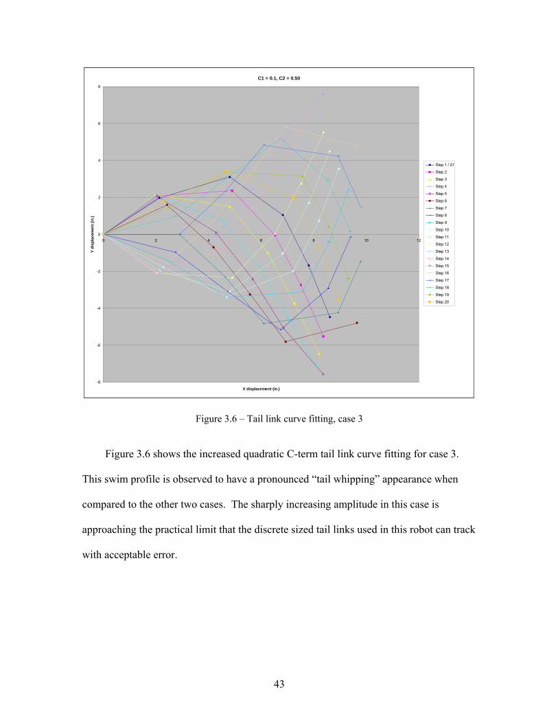
Figure 3.6 – Tail link curve fitting, case 3
Figure 3.6 shows the increased quadratic C-term tail link curve fitting for case 3.
This swim profile is observed to have a pronounced “tail whipping” appearance when
compared to the other two cases. The sharply increasing amplitude in this case is
approaching the practical limit that the discrete sized tail links used in this robot can track
with acceptable error.

44
3.4 Bio-mimetic Drive
As demonstrated in paragraph 3.3, the robot’s tail must be constructed with as many
links as practical so that the continuous curve produced by Lighthill’s equation can be
adhered to with a minimum of error. The tail constructed used PVC as the structural
material and five direct acting standard sized hobby servomotors for actuation, one
servomotor for each link. Each link is formed of two pieces, an upper and a lower half,
that are screwed together with stainless steel bolts. When the two halves are
disassembled, access to the servomotor pocket is allowed. Each servomotor is attached
to its link using four stainless steel screws. Each link is driven by the particular
servomotor on board it, with the mounting bracket that attaches the tail to the hull being
devoid of a servomotor. Each link is 2.9 in long. The servomotors, as mentioned before,
direct drive the tail links, with a 3/8 in driveshaft installed on the horn of each servomotor
running upward through the upper half of its tail link into space. Each driveshaft is
connected to the link in front of it via a clamping shaft collar fixed to the forward link
with four stainless steel screws. The driveshaft and clamping shaft collar form the upper
portion of a hinge joint. The lower portion of the hinge joint is comprised of a 3/8 in
stainless steel screw embedded in the link’s PVC structure along the same centerline as
the driveshaft; the shank of this screw rides inside a similarly sized hole in a structural
member that cantilevers off the forward link.
The final link is unique in that it has the tail hydrofoil integrated into it. The
hydrofoil is a NACA 0012 section that tapers down to a NACA 0008 section at the top,
with a slight aft taper angle. The NACA 0012 section was chosen for the base of the foil
because it provided the most advantageous thickness (a maximum thickness of 12% of

45
the chord length) to lift coefficient ratio, as well as the reason it is dimensionally similar
to propulsors used by some aquatic animals [35]. The NACA 0008 section was chosen
for the top of the foil because of its slenderness (a maximum thickness of 6% of the chord
length) and that it has an incrementally reduced coefficient of lift compared to the 0012
that equalizes out the truncation of the hydrofoil near the bottom. The NACA 0008 is
angled back from the base in a further attempt to reduce viscous drag. The NACA 0012
has been a popular choice in oscillating foil studies [4, 7, 35, 48, 53, 54, 63] and its use
here is appropriate.
The servomotors are standard sized, high torque, quick response drivers. They were
not originally intended for submersible use; each servomotor has been packed with
dielectric grease to harden it against water intrusion. Figure 3.7 shows the robot fish tail
fully assembled and ready to be installed to the forward section of the vessel. The large
inertial qualities of the tail and the powerful servomotors are likely to cause a recoiling
action in the forward section, this has been mitigated by employing techniques defined by
Lighthill and summarized in [60]. Firstly, the depth of the tail tapers as it moves aft, and
the tail fin is truncated somewhat to reduce its depth. Secondly, the mass of the robot is
concentrated in the forward section, owing to the weight of the outer hull bull-noses and
the center chassis plate. In experimental use, the fish operates with little recoil; unsteady
field effects and existing eddies in the test tank displayed dominating effects on course
error during testing. Trials subjected to these errors were obviously erroneous and were
screened out of the data collected.

46
Figure 3.7 – Robot fish tail, fully assembled
For use as a comparison to the experimental data, a numerical model of propulsive
force will be employed to verify the validity of experimental results. Kodati et al.
describe in [34] the method that the model here is based on. Observe the forces and
coordinate systems in Figure 3.8.
Figure 3.8 – Forces on oscillating foil and coordinate systems [adapted from (Kodati et al. 2007)]
In this model X and Y directions are the X and Y directions associated with the plane of
the fish robot, while C is the chord direction of the foil and N is the normal direction of

47
the foil. The model accounts for U, the swim velocity of the fish in the X direction, L,
the lift force generated by the foil, D, the drag force generated by the foil, θ, the angle
between the foil and the X direction, and α, the foil angle of attack. Foil angle and time
relative foil angle change were derived from the tables in appendix A used for link fitting.
The instantaneous total velocity vector is determined using equation 10.
222 UrU qc (10)
The foil’s instantaneous angle of attack is determined using equation 11.
)sin
cosarctan(
rU
r
(11)
The time derivative of α is determined using equation 12.
sin2)(
)sincos(22
232
UrrU
Urr
(12)
In the case of fish propulsion, we are primarily interested in the forces in the X direction.
To obtain these, first we must obtain the chordwise forces, which are lift, added mass,
and drag.
DC
amC
LCC FFFF (13)
)sin()sin( 2 qcLL
C AUCF (14)
)(
NNNCNCCNNCCCam
C UUUUF (15)
)sin()()cos(1 2
qcqc
N UrU
U (16)
)cos()()sin(1 2
qcqc
C UrU
U (17)
)cos( qcDD
C AUCF (18)

48
In the model used here, we ignore added mass, as the primary propulsion phenomenon
used by carangiform and thunniform swimmers is lift caused by vorticity [60]. The foil
area term is dropped from equations 14 and 18 because it is desired to derive force in
terms of unit foil area. Tables 3.1, 3.2, and 3.3 show the estimation of propulsive force
for each of the experimental cases given by the model. Lift and drag coefficients were
obtained from readily available information sources on NACA foils.
Table 3.1 – Propulsion force estimate, case 1, c1 = 0.1, c2 = 0.05

49
Table 3.2 – Propulsion force estimate, case 2, c1 = 0.5, c2 = 0.05
Table 3.3 – Propulsion force estimate, case 3, c1 = 0.1, c2 = 0.50

50
3.5 Control Surfaces
Like the tail fin, the side control surfaces are NACA 0012 sections that taper down
to a NACA 0008 section, with a slight rearward taper angle. These hydrofoils are
approximately seven inches in length, and provide the robot with pitch and roll control, as
well as flexibility for use in turning control.
Figure 3.9 – Robot pectoral fin control surface
The control surface actuators are 1260 degree turn, high torque, winch servomotors
driving a 5:1 ratio gear set. A driven gear is attached to each hydrofoil with four stainless
steel screws. The winch servomotor screws into an aluminum frame which is attached to
the fish robot’s center chassis plate with four stainless steel studs and nuts. The
aluminum frame houses a ball bearing that the driven gear shaft is held into by a c-clip; it
is this shaft that the driven gear is clamped to via a shaft collar and set screw assembly.

51
Figure 3.10 – Robot pectoral fin control surface actuator
3.6 Control Hardware
The robot’s control system should be sophisticated enough to accurately model fish
swimming as defined by the state matrices. For this purpose, a microcontroller of
sufficient processing speed must be chosen and it must have associated with it enough
memory capacity to contain the program modules required to set all the various
servomotor states. In addition, the robot must either operate autonomously or be
teleoperated, and have enough on-board energy storage to complete the prescribed testing
regime.
The controller selected for the project is an Innovation First Robot Controller
(IFRC). It encompasses a Microchip PICmicro® 18F8520 microcontroller and 32 kb of
memory. The 18F8520 microcontroller is capable of 10 million instructions per second,

52
which exceeds project requirements. The IFRC is equipped with eight PWM outputs,
and since the construction of the robot requires seven, it is suitable for use.
Figure 3.11 – Innovation First Robot Controller (photograph courtesy of Innovation First®, 2012)]
The IFRC is programmable in C coding language, and programs are uploaded via a
RS232 port.
Communication with the robot is also a requirement of the project, as the fish will
not be autonomous because the data collection strategy requires it to complete a very
specific task. Autonomous control is an option for the future, but for these experiments
the robot will be teleoperated from land using a 75 MHz radio transmitter and receiver.
The radio transmitter and receiver are off the shelf commercially available items, and the
receiver will be powered from the IFRC through its connection to the IFRC’s PWM
ports. The selection of radio transmitter is of particular concern due to the attenuation of
radio waves in liquid medium. A technical hurdle in teleoperated underwater robotics is
the rapid radio wave signal reduction after the point in which the waves enter the water.
Butler details the problem thoroughly in [9] and describes the method to calculate end
signal strength. The first step in calculating the end signal strength is to determine the
attenuation over distance.
53
f0173.0 (10)
In this equation α is the attenuation in dB per meter, f is the radio wave frequency in Hz
(in this case 75(10^6) Hz), and σ is the conductivity of the medium in Siemens per meter.
The average conductivity of freshwater is less than 0.1 S/m; 0.075 S/m is used as an
estimate here. Attenuation over distance is calculated to be 41.03 dB/m. The next step is
to calculate refraction loss at the water’s surface.
))6^10(4586.7log(20f
RL (11)
In this case, the refraction loss is 28.89 dB. A radio wave signal is only apparent when it
is some amount more powerful than the background thermal noise. Thermal noise is
calculated using the signal bandwidth Δf, in this case 3(10^3) Hz.
)log(10174 fPdBm (12)
Equation 12 results in a thermal noise of -93.94 dB relative to 1 milliwatt, and the
minimum discernable receive level is 10 dB above this, -83.94 dB. Using equation 13 we
are able to calculate the maximum distance D to signal loss.
dBmPRLD (13)
The end result is a distance of 1.342 m or 4.402 ft in water. This represents the robot’s
maximum diving depth before loss of communication.
All systems and subsystems of the robot fish are electrically powered which
necessitates on-board storage of electricity. The robot is equipped with two battery
packs, a 7.2 volt 2450 mAh bus to power the robot controller and radio receiver, and a
7.2 volt 12000 mAh bus to power the servo motors. The creation of a second voltage bus
was a project requirement because the robot controller selected has a four amp breaker
54
designed to protect the controller circuitry from excessive current draws on its PWM out
ports.
3.7 Control Software
The software operating the robot has a multitude of responsibilities, it must allow
for the scalar mapping of various radio transmitter control stick positions, resolution of
receiver channel input into software variables, tracking the passage of time, and time
dependant determination of servomotor states. Item three is handled by subroutine clock,
while items one, two, and four are handled by subroutine user_routines.
The controller software tracks the passage of time in a relative sense using the
subroutine clock. Subroutine clock runs continuously in the background of the control
scheme; it exploits the microcontroller’s timer 2 register to generate an interrupt in the
program every millisecond, with each interrupt increasing the clock count one. As
currently configured, the clock will reset itself every 1000 ms, as keeping time beyond
this point only complicates other aspects of the control scheme because the tail oscillation
frequency is set to 1 Hz. The time stepped servomotor states are established in
user_routines in what could be termed a look up table, using an extended if-else if-else
command.
The operating software subroutine user_routines resolves the block diagram shown
in Figure 3.12 while serving to function as the “servomotor state implementation”. This
subroutine is responsible for obtaining scalar PWM_in information from the radio
receiver.

55
Figure 3.12 – Control scheme block diagram
Setting the tail link servomotor states as described above, the subroutine user_routines
also sets the servomotor states for the control surfaces by taking information on right
control stick position, which controls pitch on the up and down and roll on the left and
right, from the radio receiver and transforming it into scalar information that is then used
in a mixing function to set the control surface angles via superposition.
User
PWM_in1 (throttle)
PWM_in3 (pitch)
PWM_in4 (roll)
Radio Transmitter
PWM Control Signal Radio
Receiver
Ch.1 (roll)
Ch.2 (pitch)
Ch.3 (throttle)
IFRC
+ VDC
-
Micro Controller
Servomotor State
Implementation
PWM State
Implementation
Bus #1
Tail Servomotor
Digital Encode
λ1
Tail Servomotor
Digital Encode
λ2
Tail Servomotor
Digital Encode
λ3
Tail Servomotor
Digital Encode
λ4
Tail Servomotor
Digital Encode
λ5
Control Surface
Digital Encode
Ω1
Control Surface
Digital Encode
Ω2
+ VDC
- Bus #2
Γ1
Γ2
Γ3
Γ4
Γ5
ε1
ε2

56
CHAPTER 4
EXPERIMENTAL EXECUTION
4.1 Laboratory Set-up
The experiments were held at University of Illinois Urbana-Champaign’s own Ven
Te Chow Hydrosystems Laboratory. The laboratory houses many different water tanks
and flumes; the tank used in these experiments was the 24.25 ft long, 9 ft wide, and 7.5 ft
deep MARGINS tank. This tank was originally constructed to study sediment deposition
on the continental shelf, but it was configured for use in these experiments. The floor of
the tank and water level were set such that an effective depth of approximately twenty
inches was achieved. This allowed for access inside the tank in order for the test trials to
be facilitated.
Figure 4.1 – MARGINS tank, front

57
Figure 4.2 – MARGINS tank, side
Figure 4.3 – MARGINS tank, top

58
The MARGINS tank’s wetted area is approximately 15 ft long by 9 ft wide, with the first
approximately 6 ft of length dedicated to a sloped section required by its original
purposing. The sloped section reduces the tank’s effective dimensions to 9 ft long by 9 ft
wide, which is more than adequate for the tests conducted. The main considerations for
tank dimensions are that they be sizable enough to avoid causing boundary layer effects
on the robot, inducing viscous drag, or causing eddies as the robot swims by.
The robot used in these tests was the Aquatic High-fidelity Actuation Biomimic fish
robot (AHAB), designed and fabricated by the author. AHAB is 42 inches long, 30
inches wide from pectoral fin tip to pectoral fin tip, and 17 inches tall from lowest point
to top of the highest point of the top hull. The robot is very close to neutrally buoyant,
having a very slow rise to the surface. This facilitated testing, as the robot would remain
at the water surface with approximately 1/16 inch of the top buoyancy compensator
assembly protruding into atmosphere and the tail fin well submerged. The buoyancy
compensator assembly is part of the robot’s structural design and assists with counter-
acting the presence of heavier hardware such as batteries, fasteners, and such. The
buoyancy compensator also mitigates some of the non-minimum phase behaviors that
might otherwise be present during operation, such as uncontrolled rolling and un-
counteracted moments about the robot’s center of gravity. Many of the details of
AHAB’s construction are given in chapter 3.

59
Figure 4.4 – University of Illinois’s AHAB fish robot
The lab apparatus was configured with two DSLR cameras for use as data collection
devices. The first camera was configured to record video and was mounted to a cross
member running between two a-frames that straddled the tank. This camera was pointed
straight down on the test area at a height of approximately 4 ft above the water level and
operated at 30 Hz. The second camera was configured to record high resolution still
images of the test area from an elevated position on the tank catwalk. Images taken by
this camera were time stamped to an accuracy of a millisecond, and images were
collected at 1 Hz. The view from camera #1 can be seen in Figure 4.5 and the view from
camera #2 can be seen in Figure 4.6.
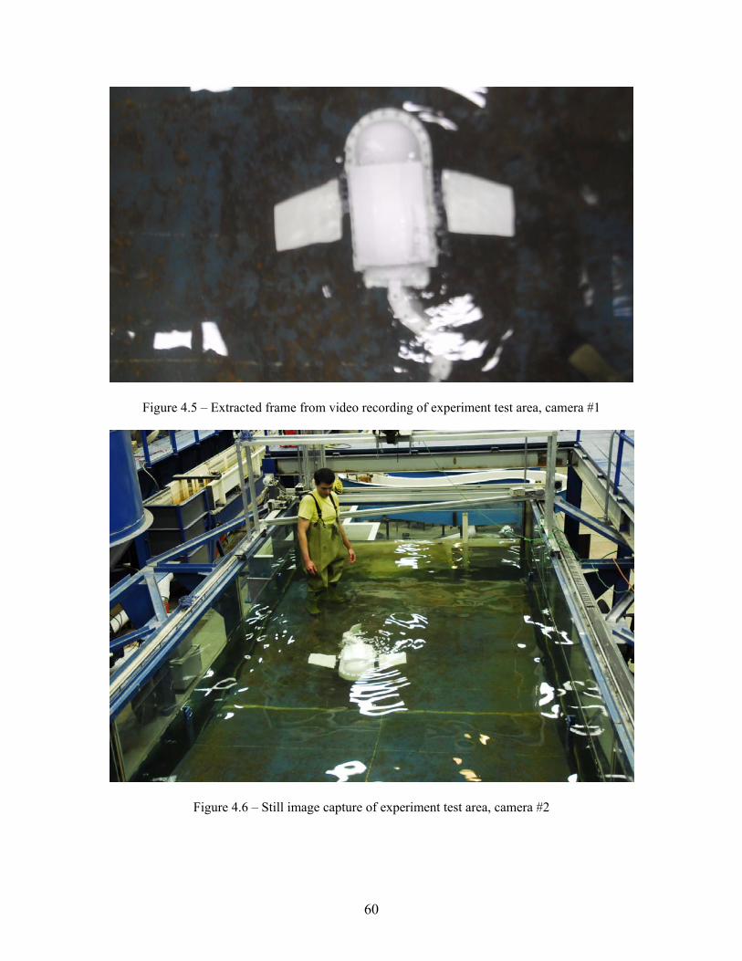
60
Figure 4.5 – Extracted frame from video recording of experiment test area, camera #1
Figure 4.6 – Still image capture of experiment test area, camera #2

61
A sketch of the data collection set-up is shown in Figure 4.7. The purpose of taking
two sets of experimental data was to allow one to verify the results of the other, as
camera #1 had a superior frame rate but lower resolution, and camera #2 had a superior
resolution but lower frame rate. The still images taken by camera #2 require rectification
by Matlab or similar package prior for use in comparison with the data from camera #1.
The rectification points used were four spud points on the tank that had precise locations.
They can be seen in Figure 4.6 as the four blue structural angles protruding through the
water line, one at each corner of the horizontal tank floor section.
Figure 4.7 – Sketch of experimental data collection strategy
4.2 Test Regime
Since the purpose of the testing was to characterize three different swim profiles, the
tests were structured in three phases. The program containing case 1 was loaded into the
Catwalk
Camera #1
Camera #2
Robot
Tank
WaterLevel

62
controller memory, the controller and servomotor voltage buses verified to be fully
charged, and the robot assembled. The robot was taken into the tank and trials were
accumulated until three quality runs were obtained. Quality was determined based on the
lack of any outside induced moments on the robot, RF interference with the teleoperation
system, or issues with the data collection equipment. Once data had been taken on the
first case, the robot was partially disassembled to access the controller and the program
changed to case 2. The bus voltages were verified to be unchanged within measuring
equipment accuracy. The large storage capacity of the servomotor voltage bus and the
small draw by the robot controller on its voltage bus resulted in very little variation in
voltage throughout testing, ranging from a high of 7.64 V to a low of 7.56 V on the
servomotor bus and no measurable change in the controller bus. With the program
changed and robot voltages verified, the experimental process was repeated for case 2.
The overall procedure was repeated again for case 3.
Activities in the tank consisted of a person maneuvering the robot to the rear of the
tank where the depth is consistent, positioning it near the limit of the test area being
recorded by camera #1, steadying it while perturbations in the water subside, then
releasing it carefully so as to not enact an impulse upon it. Very shortly after release, the
operator triggers the controller to swim forward. Successful trials swim almost entirely
straight, some recoil induced in the forward section by the tail motion causes the
swimming to meander small amounts.
As mentioned earlier, the data collected by camera #2 requires rectification prior to
use. This process consisted of correcting the still images for the barrel distortion of the
camera then applying a rectification algorithm contained in Matlab to the images. The

63
rectification required selecting points of known location in the image to use as reference
for the algorithm. Once the algorithm was given frame correction for X and Y scales, the
script developed for the post processing of the experimental data was given a particular
point on the robot to track. As the script advanced through the time stamped frames, it
was able to develop X location, Y location, and time elapsed information, and was able to
calculate point velocity. Typical visual output from the script is shown in Figure 4.8.
Figure 4.8 – Particle tracking trajectory obtained from Matlab rectifying script
4.3 Observations
Observations taken during testing were primarily to obtain data on swim velocity to
determine the effect C-term wave envelope coefficients have on the propulsion efficiency
of the robot. The rectified velocities and other data gathered are presented here in their
raw form in Tables 4.1 through 4.9. Two items are of note, firstly some of the raw data
collected has been truncated in the interest of ensuring experimental accuracy, and

64
secondly, the time elapsed in each experimental run varied from trial to trial resulting in
data tables of differing length. The first consideration is for the purpose of obtaining
valid results; there exists some concerns on how well the rectification algorithm evaluates
velocity at distances very close to the camera. Additive to this issue is the fact that the
tank floor slopes upward as the robot comes close to the camera, resulting in the
introduction of boundary layer effects and other hydrodynamic phenomenon on the
acting on the robot. Since the numerical model estimating propulsive force is absent
these effects, runs have been shortened to eliminate them. The second consideration is of
little consequence, as the data will show, apparent plateaus appear in the velocity data
indicating that trials were long enough to gain an experimental outcome.
Table 4.1 – Robot swim velocity data, case 1, C1=0.1, C2=0.05, trial 1

65
Table 4.2 – Robot swim velocity data, case 1, C1=0.1, C2=0.05, trial 2
Table 4.3 – Robot swim velocity data, case 1, C1=0.1, C2=0.05, trial 3
The trial 1 and trial 3 data for case one shows some evidence of a meandering swim
behavior, but this had little apparent effect on the instantaneous magnitude of velocity
data, as evidenced by trial 2 having the least consistent acceleration of the three trials.
Table 4.4 – Robot swim velocity data, case 2, C1=0.5, C2=0.05, trial 1

66
Table 4.5 – Robot swim velocity data, case 2, C1=0.5, C2=0.05, trial 2
Table 4.6 – Robot swim velocity data, case 2, C1=0.5, C2=0.05, trial 3
The instantaneous magnitude of velocity data for the case 2 data is very consistent from
trial to trial. This maybe attributable to this swim profile’s “smooth” gait and the lack of
recoil forces causing jerk. Conversely, trials for case 3 tended to slalom, or have a back
and forth gait. This might have to do with the large changes in foil effective angle of
attack during its cycle.

67
Table 4.7 – Robot swim velocity data, case 3, C1=0.1, C2=0.50, trial 1

68
Table 4.8 – Robot swim velocity data, case 3, C1=0.1, C2=0.50, trial 2
Table 4.9 – Robot swim velocity data, case 3, C1=0.1, C2=0.50, trial 3

69
CHAPTER 5
EXPERIMENTAL RESULTS
5.1 Experimental Trends
The analysis of the experimental results reveals a number of trends. Figures 5.1,
5.2, and 5.3 illustrate time dependant velocity data from the experimental trials; in each
experimental grouping, a plateau forms. Figure 5.1 displays the data for the three
successful trials in the C1=0.1, C2=0.05 case. The line graph demonstrates a plateau that
indicates as t , U 0.375 ft/s.
Robot Velocity vs. Time elapsed
0
0.05
0.1
0.15
0.2
0.25
0.3
0.35
0.4
0.45
0.5
0 5 10 15 20 25 30
Time Elapsed (s)
Ro
bo
t V
elo
city
(ft
/s)
C1=0.1, C2=0.05, Trial 1
C1=0.1, C2=0.05, Trial 2
C1=0.1, C2=0.05, Trial 3
Figure 5.1 – Robot swim velocity vs. time elapsed, case 1, C1=0.1, C2=0.05
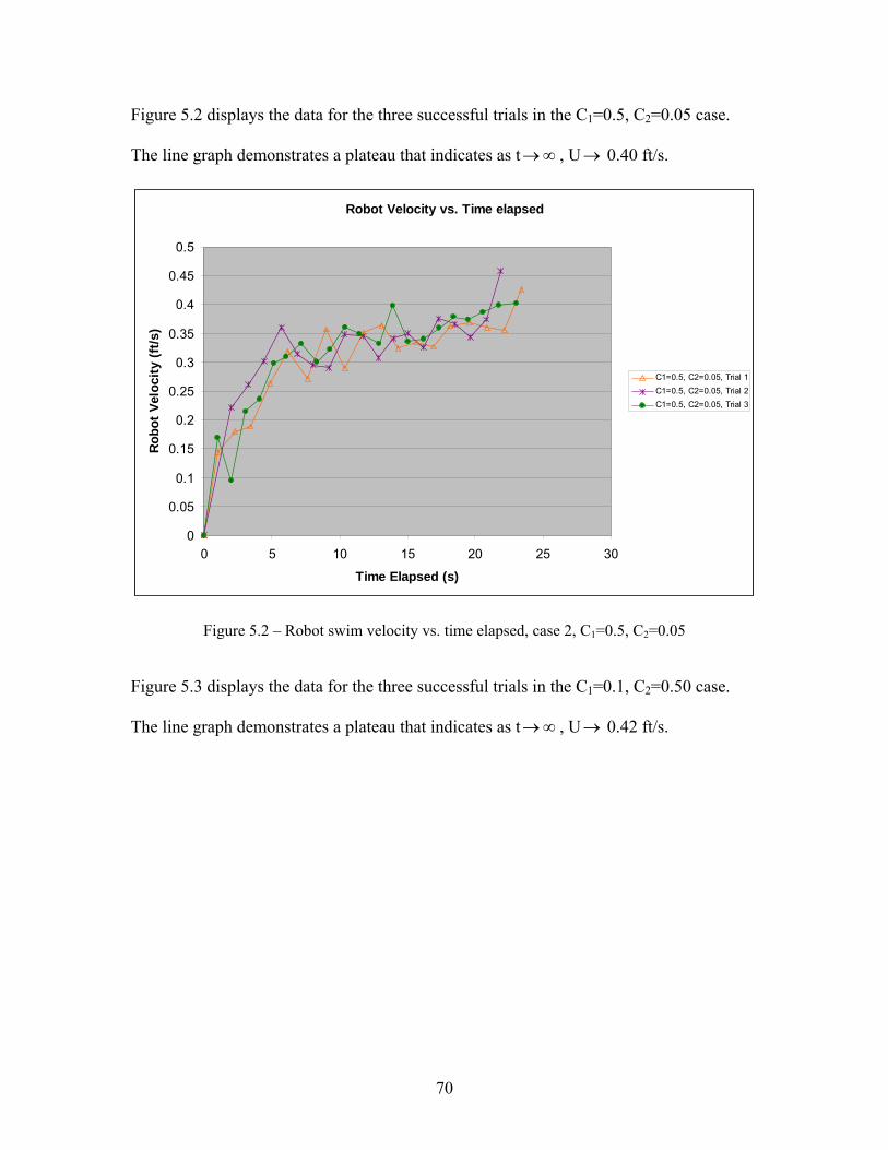
70
Figure 5.2 displays the data for the three successful trials in the C1=0.5, C2=0.05 case.
The line graph demonstrates a plateau that indicates as t , U 0.40 ft/s.
Robot Velocity vs. Time elapsed
0
0.05
0.1
0.15
0.2
0.25
0.3
0.35
0.4
0.45
0.5
0 5 10 15 20 25 30
Time Elapsed (s)
Ro
bo
t V
elo
city
(ft
/s)
C1=0.5, C2=0.05, Trial 1
C1=0.5, C2=0.05, Trial 2
C1=0.5, C2=0.05, Trial 3
Figure 5.2 – Robot swim velocity vs. time elapsed, case 2, C1=0.5, C2=0.05
Figure 5.3 displays the data for the three successful trials in the C1=0.1, C2=0.50 case.
The line graph demonstrates a plateau that indicates as t , U 0.42 ft/s.

71
Robot Velocity vs. Time elapsed
0
0.05
0.1
0.15
0.2
0.25
0.3
0.35
0.4
0.45
0.5
0 5 10 15 20 25 30
Time Elapsed (s)
Ro
bo
t V
elo
city
(ft
/s)
C1=0.1, C2=0.50, Trial 1
C1=0.1, C2=0.50, Trial 2
C1=0.1, C2=0.50, Trial 3
Figure 5.3 – Robot swim velocity vs. time elapsed, case 3, C1=0.1, C2=0.50
Figure 5.4 illustrates the comparison of the convergence value of velocity for each of the
experimental cases with the propulsive force estimates developed in section 3.4. As one
can see, the numerical model and laboratory results appear to validate one another; as
propulsion force increases in the theoretical, propulsion speed increases in the
experimental.
Another interesting trend found in the results from the numerical model is that for
the high Strouhal numbers that prevailed in these experiments, the highest lifts generated
by the foil were at extreme angles of attack, resulting at 79°, 84°, and 67° for case 1, case
2, and case 3 respectively. This finding is seemingly validated in the experimental data
on thrust coefficient vs. foil effective angle of attack and Strouhal number in [54], where
it is apparent that as St increases larger angles of attack become viable without stalling.

72
This behavior has implications for larger, mission scale, underwater robots where swim
speeds are slower and the wake amplitudes are higher.
4
4.5
5
5.5
6
6.5
7
7.5
8
8.5
9
Case 1, C1=0.1,C2=0.05
Case 2, C1=0.5,C2=0.05
Case 3, C1=0.1,C2=0.50
Fo
rce
per
Un
it A
rea
(lb
f/ft
^2)
0.300
0.350
0.400
0.450
0.500
0.550
Ro
bo
t V
elo
city
(ft
/s)
Force per UnitArea (lbf/in^2)
Robot Velocity(ft/s)
Figure 5.4 – Theoretical force per unit area of foil compared with experimental velocity attained
5.2 Result Discussion
The experimental data shows a discernable difference in the propulsive efficiency in
the three experimental cases suggesting that C-term wave envelope coefficients can be
used in an optimization approach. The optimization in propulsive efficiency appears to
be driven primarily by the larger foil effective angles of attack generated by swim
profiles with larger wave envelope coefficients.
The experimental results correlating with results from a numerical lift based model
of fish swimming points to validation to the theory that carangiform swimmers rely
primarily on hydrodynamic lift due to vortical effects for propulsion. The numerical

73
model used determined lift, drag, and added mass effects in the generation of foil
chordwise forces, and despite a simplification applied to the model to eliminate added
mass effects, the numerical model correlated well with the experimental data.

74
CHAPTER 6
CONCLUSIONS
6.1 Concluding Analysis
The work completed in the scope of this project has been extensive and has
provided an apparent experimental conclusion. In summation, the project consisted of a
experiment planning and construction phase where a robotic fish was built, an
experimental phase where three swim profiles were characterized, and an data resolution
and interpretation phase.
A biomimetic carangiform robotic fish has been constructed as a functional
experimental apparatus. The robot constructed possesses a propulsive section with five
short links capable of fitting the sinusoids produced by Lighthill’s model of fish tail
motion with commendable accuracy. This robot is of solid construction suitable for
heavy usage, is capable of pitch and yaw control, is nearly neutrally buoyant, and allows
for expansion in features such as the inclusion of analog and digital sensors. It is viable
for use in future work involving aquatic mobile robotics research.
The characterization of three cases of varied C-term wave envelope coefficients for
Lighthill’s model of fish motion has been accomplished theoretically, applied to a
biomimetic fish robot using a link fitting technique, and tested experimentally. The three
different swim profiles obtained from the cases have been evaluated against each other,
as well as against a theoretical estimation of propulsive force. Of the three cases of C-
term wave envelope coefficients tested, one has been identified as yielding the highest
propulsion speed. This case of C-term coefficients provides optimal efficiency in

75
comparison to the other two, as, in the experiments considered here, propulsion speed is
analogous to propulsion efficiency because the power consumption of the system changes
little due to the constant running current of the actuators.
A sophisticated experimental technique in which a virtual isometric image is
rectified into a 2-dimensional planar representation to obtain velocity data from a mobile
robot has been demonstrated. The methodology of utilizing a Matlab script and built in
algorithms to track particles in still images and determine changes in X-Y coordinates has
been detailed, and when used with temporal metadata inherent to the images, the
acquisition of time dependant information now becomes possible.
6.2 Contribution to the Current Knowledge
This project incorporated two novel items of work. The first is the prediction of
propulsive forces based on mechanical fish tail linkage kinematics using a lift based
theory. The method was able to estimate the propulsive lift and drag on the oscillating
foil, with estimates correlating to the experimental results. The implication of this is that
the model can be used as a design tool in future linkage motion planning. The second
novel item of work was the determination of trends in C-term wave envelope effects on
propulsion speed and efficiency of a mobile robotic biomimetic fish. The trends in the
fish motion wave envelope suggest that C-term coefficients that generate larger foil
effective angles of attack are more efficient than those otherwise. This finding points the
direction for future investigations into swim profile optimization.

76
6.3 Future Work
There exists potential for future work in both the realm of C-term wave envelope
investigations and in the improvement of the robot fish lab apparatus. The most obvious
avenue for future work is to try more C-term values to see if any further trends develop.
Other variables to investigate as they relate to wave envelope are caudal fin shape,
namely ones with higher lift coefficients, Strouhal number and the viability of tuning it to
values used in other experiments to observe whether results are repeatable, and finally
manipulation of C-terms to investigate specific foil effective angles of attack.
Future work that should be considered for completion on the robot fish apparatus
itself is the addition of a fleshy covering for the tail section, to determine if propulsive
force could be improved by preventing fluid flow lines from crossing the tail linkage.
Autonomous control could be added to the robot so that it could conduct experiments on
its own, removing the need for a person in the tank to stage it and the need for a strong
signal from a land based radio transmitter.

77
REFERENCES
[1] I. Akhtar and R. Mittal, “A biologically inspired computational study of flow past
tandem flapping foils,” in 35th AIAA Fluid Dynamics Conf. and Exhibit, Toronto,
ON, 2005.
[2] J.M. Anderson and N.K. Chhabra, “Maneuvering and stability performance of a
robotic tuna,” Integrative and Comparative Biology, no. 42, pp. 118-126, 2002.
[3] J.M. Anderson and P.A. Kerrebrock, “The vorticity control unmanned undersea
vehicle: an autonomous robot tuna,” in 11th International Symposium on
Unmanned Untethered Submersible Technology, Durham, NH, Aug. 1999, pp.
63-70.
[4] J.M. Anderson et al., “Oscillating foils of high propulsive efficiency,” Journal of
Fluid Mechanics, no. 360, pp. 41-72, 1998.
[5] P. Ausoni et al., “2D oscillating hydrofoil,” in 2nd IAHR International Meeting
Workgroup on Cavitation and Dynamic Problems in Hydraulic Machinery and
Systems, Timisoara, Romania, 2007, pp. 229-234.
[6] P.R. Bandyopadhyay, “Trends in biorobotic autonomous undersea vehicles,”
IEEE Journal of Oceanic Engineering, vol. 30, no. 1, Jan. 2005, pp. 109-139.
[7] D.S. Barrett et al., “Drag reduction in fish-like locomotion,” Journal of Fluid
Mechanics, vol. 392, pp. 183-212, 1999.
78
[8] B. Behkam and M. Sitti, “Design methodology for biomimetic propulsion of
miniature swimming robots,” Journal of Dynamic Systems Measurement &
Control, vol. 128, no. 1, pp. 36-44, March 2006.
[9] L. Butler, “Underwater radio communication,” Amateur Radio, April 1987.
[10] Z. Chen et al., “Modeling of biomimetic robotic fish propelled by an ionic
polymer-metal caudal fin,” IEEE ASME Transactions on Mechatronics, vol. 15,
no. 3, pp. 448-459, June 2010.
[11] J.E. Colgate and K.M. Lynch, “Control problems solved by a fish’s body and
brain: a review,” in IEEE Journal of Ocean Engineering, vol. 29, no. 3, pp. 660-
673, July 2004.
[12] J. Edd et al., “Biomimetic propulsion for a swimming surgical micro-robot,” in
IEEE Intelligent Robotics and Systems Conference, Las Vegas, USA, 2003, pp. 1-
6.
[13] F.E. Fish et al., “Hydrodynamic flow control in marine mammals,” Integrative
and Comparative Biology, pp. 1-13, May 2008.
[14] F.E. Fish, “Power output and propulsive efficiency of swimming bottlenose
dolphins Tursiops truncates,” Journal of Experimental Biology, no. 185, pp. 179-
193, 1993.

79
[15] F.E. Fish, “The myth and reality of Gray’s paradox: implication of dolphin drag
reduction for technology,” Bioinspiration & Biomimetics, no. 1, pp. r17-r25,
2006.
[16] J.D. Geder et al., “Fuzzy logic PID based control design and performance for a
pectoral fin propelled unmanned underwater vehicle,” in International
Conference on Control, Automation and Systems, Seoul, Korea, Oct. 2008, pp. 1-
7.
[17] P. Giguere et al., “Characterization and modeling of rotational responses for an
oscillating foil underwater robot,” in IEEE RSJ International Conference on
Intelligent Robots and Systems, Beijing, China, Oct. 2006, pp. 3000-3005.
[18] R. Gopalkrishnan et al., “Active vorticity control in a shear flow using a flapping
foil,” Journal of Fluid Mechanics, no. 274, pp. 1-21, 1994.
[19] F. Guo and G. Peng, “Simulation fitting method for setting motion parameters of
robotic fish,” unpublished.
[20] D.R. Hedgepeth, “A framework for modeling steady turning of robotic fish,” in
IEEE International Conf. on Robotics and Automation, Kobe, Japan, 2009, pp.
2669-2674.
[21] K. Hirata, “Development of experimental fish robot,” in Sixth International
Symposium on Marine Engineering, pp. 1-4, 2000.

80
[22] F.S. Hover, “Effect of angle of attack profiles in flapping foil propulsion,”
Journal of Fluids and Structures, no. 19, pp. 37-47, 2004.
[23] H. Hu et al., “Design of 3D swim patterns for autonomous robotic fish,” in IEEE
International Conference on Intelligent Robots and Systems, Beijing, China, Oct.
2006, pp. 2406-2411.
[24] H. Hu and J. Liu, “A 3D simulator for autonomous robotic fish,” International
Journal of Automation and Computing, vol. 1, no. 1, pp. 42-50, 2004.
[25] H. Hu and J. Liu, “Biological inspiration: from carangiform fish to multi-joint
robotic fish,” Journal of Bionic Engineering, no. 7, pp. 35-48, 2010.
[26] H. Hu, “Biologically inspired design of autonomous robotic fish at Essex,” in
IEEE Chapter Conference on Advances in Cybernetic Systems, 2006, pp. 1-8.
[27] T. Hu et al., “Biological inspirations, kinematics modeling, mechanism design
and experiments on an undulating robotic fin inspired by Gymnarchus niloticus,”
Mechanism and Machine Theory, no. 44, pp. 633-645, 2009.
[28] M. Hur et al., “Hinf controller design of an ostraciiform swimming fish robot,”
Indian Journal of Marine Sciences, vol. 38, no. 3, pp. 302-307, 2009.
[29] E. Kanso and J.E. Marsden, “Optimal motion of an articulated body in a perfect
fluid,” in 44th IEEE Conference on Decision and Control, Seville, Spain, 2005,
pp. 2511-2516.

81
[30] E. Kanso et al., “Locomotion of articulated bodies in a perfect fluid,” Journal of
Nonlinear Science, vol. 15, no. 4, pp. 255-289, 2005.
[31] S.D. Kelly and H. Xiong, “Controlled hydrodynamic interactions in schooling
aquatic locomotion,” in 44th IEEE Conference on Decision and Control, Seville,
Spain, 2005, pp. 3904-3910.
[32] T. Knutsen, “Designing an underwater eel-like robot and developing anguilliform
locomotion control,” unpublished.
[33] F. Khorrami et al., “A multi-body approach for 6DOF modeling of biomimetic
autonomous underwater vehicles with simulation and experimental results,” in
Control Applications CCA Intelligent Control ISIC 2009 IEEE, 2009, pp. 1282-
1287.
[34] P. Kodati et al., “Micro autonomous robotic ostraciiform: hydrodynamics, design
and fabrication,” in IEEE International Conference on Robotics and Automation,
Rome, Italy, April 2007, pp. 960-965.
[35] G.V. Lauder et al., “Fish biorobotics: kinematics and hydrodynamics of self-
propulsion,” The Journal of Experimental Biology, no. 210, pp. 2767-2780, 2007.
[36] J.C. Liao et al., “The Karman gait: novel body kinematics of rainbow trout
swimming in a vortex street,” The Journal of Experimental Biology, no. 206, pp.
1059-1073, 2003.

82
[37] S. Licht et al., “Design and projected performance of a flapping foil AUV,” IEEE
Journal of Oceanic Engineering, vol. 23, no. 3, pp. 786-794, July 2004.
[38] M.J. Lighthill, “Note on the swimming of slender fish,” Journal of Fluid
Mechanics, no. 9, pp. 305-317, 1960.
[39] J. Liu et al., “Novel mechatronics design for a robotic fish,” in IEEE RSJ
International Conference on Intelligent Robots and Systems, Edmont, Alberta,
Canada, Aug. 2005, pp. 2077-2082.
[40] J. Liu and H. Hu, “A methodology of modelling fish-like swim patterns for
robotic fish,” in IEEE International Conference on Mechatronics and
Automation, Harbin, China, Aug. 2007, pp. 1316-1321.
[41] J. Liu and H. Hu, “Mimicry of sharp turning behaviours in a robotic fish,” in
IEEE International Conference on Robotics and Automation, Barcelona, Spain,
April 2005, pp. 3329-3334.
[42] K.H. Low and A. Willy, “Biomimetic motion planning of an undulating robotic
fish fin,” Journal of Vibration and Control, vol. 12, no. 12, pp. 1337-1360, 2006.
[43] K.H. Low, “Locomotion simulation and system integration of robotic fish with
modular undulating fin,” International Journal of Simulation, vol. 7, no. 8, pp.
64-77, 2006.

83
[44] M.A. MacIver et al., “Designing future underwater vehicles: principles and
mechanisms of the weakly electric fish,” IEEE Journal of Oceanic Engineering,
vol. 29, no. 3, pp. 651-659, July 2004.
[45] R. Mason and J. Burdick, “Construction and modelling of a carangiform robotic
fish,” Experimental Robotics, no. 4, pp. 235-242, 2000.
[46] B. Massey, “Effects of shed vortices in fluid force simulations for a pitching and
heaving flat plate,” M.S. thesis, Aeronautics & Astronautics, Univ. of
Washington, Seattle, WA, 2004.
[47] E. Mbemmo et al., “Modeling of biomimetic robotic fish propelled by an ionic
polymer-metal composite actuator,” in IEEE Conference on Robotics and
Automation, Pasadena, CA, May 2008, pp. 689-694.
[48] J. Melli and C.W. Rowley, “Models and control of fish-like locomotion,” Journal
of Experimental Mechanics, vol. 50, no. 9, pp. 1355-1360, 2010.
[49] D. Mohammadshahi et al., “Design, fabrication and hydrodynamic analysis of a
biomimetic robot fish,” International Journal of Mechanics, vol. 2, no. 4, pp. 59-
66, 2008.
[50] K.A. Morgansen et al., “Nonlinear control methods for planar carangiform robot
fish locomotion,” in IEEE International Conference on Robotics and Automation,
Seoul, Korea, May 2001, pp. 427-434.

84
[51] K.A. Morgansen et al., “Trajectory stabilization for a planar carangiform robot
fish,” IEEE International Conference on Robotics and Automation, Washington,
D.C., May 2002, pp. 756-762.
[52] E. Papadopoulos et al., “Design, control, and experimental performance of a
teleoperated robotic fish,” in 17th Mediterranean Conference on Control &
Automation, Thessaloniki, Greece, 2009, pp. 766-771.
[53] G. Pedro et al., “A numerical study of the propulsive efficiency of a flapping
hydrofoil,” International Journal for Numerical Methods in Fluids, no. 42, pp.
493-526, 2003.
[54] D.A. Read et al., “Forces on oscillating foils for propulsion and maneuvering,”
Journal of Fluids and Structures, no. 17, pp. 163-183, 2003.
[55] J.J. Rohr and F.E. Fish, “Strouhal numbers and optimization of swimming by
odontocete cetaceans,” Journal of Experimental Biology, no. 207, pp. 1633-1642,
2004.
[56] C. Rossi et al., “SMA control for bio-mimetic fish locomotion,” in 7th
International Conference on Informatics in Control, Automation and Robotics,
Madiera, Portugal, 2010, pp. 147-152.
[57] C. Rossi et al., “Towards motor-less and gear-less robots: a bio-mimetic fish
design,” unpublished.

85
[58] S. Saimek and P.Y. Li, “Longitudinal motion planning and control of a swimming
machine,” International Journal of Robotics, vol. 23, no. 1, pp. 27-53, Jan. 2004.
[59] T. Schnipper et al., “Vortex wakes of a flapping foil,” Journal of Fluid
Mechanics, no. 633, pp. 411-423, 2009.
[60] M. Sfakiotakis et al., “Review of fish swimming modes for aquatic locomotion,”
IEEE Journal of Oceanic Engineering, vol. 24, no. 2, pp. 237-252, April 1999.
[61] E. Shimizu et al., “Shape optimization of fish tail propulsion with hydro-elastic
effects,” JSME Annual Meeting 2004, no. 6, pp. 145-146, 2004.
[62] R.K. Shukla and J.D. Eldredge, “An inviscid model for vortex shedding from a
deforming body,” Theoretical Computational Fluid Dynamics, no. 21, pp. 343-
368, 2007.
[63] B.J. Simpson et al., “Experiments in direct energy extraction through flapping
foils,” in Proceedings of the Eighteenth International Offshore and Polar
Engineering Conference, Vancouver, BC, Canada, July 2008, pp. 370-376.
[64] S. Srigrarom et al., “Experimental study of oscillating sd8020 foil for
propulsion,” in 16th Australiasian Fluid Mechanics Conference, Gold Coast,
Austrialia, Dec. 2007, pp. 1291-1294.
[65] M. Tan et al., “A framework for biomimetic robot fish’s design and its
realization,” in American Control Conference, Portland, OR, 2005, pp. 1593 –
1598.

86
[66] X. Tan et al., “An autonomous robotic fish for mobile sensing,” in IEEE
International Conf. on Intelligent Robots and Systems, Beijing, China, 2006, pp.
5424-5429.
[67] A.H. Techet et al., “Separation and turbulence control in biomimetic flows,”
Flow, Turbulence and Combustion, vol. 71, no. 1, pp. 105-118, 2003.
[68] M.S. Triantafyllou et al., “Review of experimental work in biomimetic foils,”
IEEE Journal of Oceanic Engineering, vol. 29, no. 3, pp. 585-594, July 2004.
[69] M.S. Triantafyllou et al., “Review of hydrodynamic scaling laws in aquatic
locomotion and fishlike swimming,” Applied Mechanics Reviews, no. 58, pp. 226-
237, July 2005.
[70] M.S. Triantafyllou et al., “Vorticity control in fish-like propulsion and
maneuvering,” Integrative and Comparative Biology, no. 42, pp. 1026-1031.
[71] M.S. Triantafyllou and G.S. Triantafyllou, “An efficient swimming machine,”
Scientific American, vol. 272, no. 3, pp. 64-71, Mar. 1995.
[72] C.S. Turner, “Johnson-Nyquist noise,” unpublished.
[73] D. Tzeranis et al., “On the design of an autonomous robot fish,” in 11th
Mediterranean Conference on Control and Automation, Rhodes, 2003, pp. 1-6.
[74] C. Watts et al., “The design and construction of the submersible hybrid
autonomous rover craft,” unpublished.

87
[75] L. Wen et al., “Hydrodynamic experimental investigation on efficient swimming
of robotic fish using self-propelled method,” International Journal of Offshore
and Polar Engineering, vol. 20, no. 3, pp. 167-174, 2010.
[76] M.W. Westneat and J.A. Walker, “Mechanical design of fin propulsion:
kinematics, hydrodynamics, morphology and motor control of pectoral fin
swimming in fishes,” unpublished.
[77] M.J. Wolfgang et al., “Near-body flow dynamics in swimming fish,” Journal of
Experimental Biology, no. 203, pp. 2303-2327, 1999.
[78] Q. Yan et al., “Parametric research of experiments on a carangiform robotic fish,”
Journal of Bionic Engineering, no. 5, pp. 95-101, 2008.
[79] J. Young et al., “Thrust and efficiency of propulsion by oscillating foils,”
Computational Fluid Dynamics, no. 6, pp. 313-318, 2006.
[80] J. Yu et al., “A simplified propulsive model of bio-mimetic robot fish and its
realization,” Robotica, no. 23, pp. 101-107, 2005.
[81] W. Zhang et al., “A new type of hybrid fish-like microrobot,” International
Journal of Automation and Computing, vol. 1, no. 4, pp. 358-365, 2006.
[82] Q. Zhu et al., “Three-dimensional flow structures and vorticity control in fish-like
swimming,” Journal of Fluid Mechanics, no. 468, pp. 1-28, 2002.

88
APPENDIX A
SERVOMOTOR STATE DETERMINATION
A.1 Case 1, C1 = 0.1, C2 = 0.05
The servomotor states were determined using the method outlined in paragraph 3.3.
The first case involved a linear coefficient of 0.1 and a quadratic coefficient of 0.05. The
Table A.1 was derived from an iterative scheme to fit endpoints to the curves derived
from the Lighthill equation using tail links that were 2.9 inches long.
Table A.1 – Absolute x,y positional data for tail link end points, case 1; link 0 assumed start 0,0
Once a matrix of absolute positions of each link end point has been determined, it is
transformed into absolute and relative tail link angles shown in Table A.2. Again, angle
θ represents the absolute angle, relative to the x-axis, that the tail link must be rotated to.
Angle λ represents the relative angle that the servo must rotate to correctly position the
link. The previous tail link’s absolute angle must be subtracted from the particular tail

89
link’s absolute angle to compensate for the previous tail link’s rotation, and thus λ is
obtained.
Table A.2 – Absolute and relative tail link angle position, case 1
A.2 Case 2, C1 = 0.5, C2 = 0.05
The servomotor states for case 2 were determined using the same process described
in paragraph A.1. The second case involved a linear coefficient of 0.5 and a quadratic
coefficient of 0.05. The Table A.3 was derived from an iterative scheme to fit endpoints
to the curves derived from the Lighthill equation, again, using tail links that were 2.9
inches long.

90
Table A.3 – Absolute x,y positional data for tail link end points, case 2; link 0 assumed start 0,0
Once a matrix of absolute positions of each link end point has been determined, it is
transformed into absolute and relative tail link angles shown in Table A.4. Again, angle
θ represents the absolute angle, relative to the x-axis, that the tail link must be rotated to.
Angle λ represents the relative angle that the servo must rotate to correctly position the
link. The previous tail link’s absolute angle must be subtracted from the particular tail
link’s absolute angle to compensate for the previous tail link’s rotation, and thus λ is
obtained.
Table A.4 – Absolute and relative tail link angle position, case 2
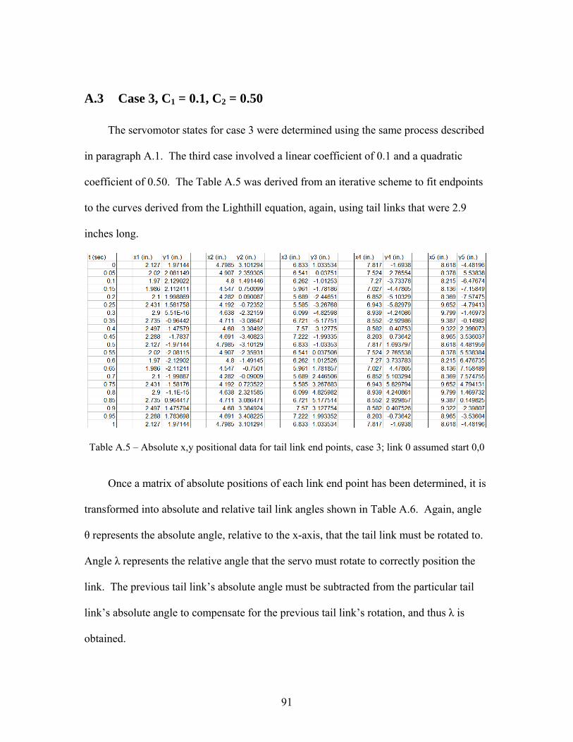
91
A.3 Case 3, C1 = 0.1, C2 = 0.50
The servomotor states for case 3 were determined using the same process described
in paragraph A.1. The third case involved a linear coefficient of 0.1 and a quadratic
coefficient of 0.50. The Table A.5 was derived from an iterative scheme to fit endpoints
to the curves derived from the Lighthill equation, again, using tail links that were 2.9
inches long.
Table A.5 – Absolute x,y positional data for tail link end points, case 3; link 0 assumed start 0,0
Once a matrix of absolute positions of each link end point has been determined, it is
transformed into absolute and relative tail link angles shown in Table A.6. Again, angle
θ represents the absolute angle, relative to the x-axis, that the tail link must be rotated to.
Angle λ represents the relative angle that the servo must rotate to correctly position the
link. The previous tail link’s absolute angle must be subtracted from the particular tail
link’s absolute angle to compensate for the previous tail link’s rotation, and thus λ is
obtained.

92
Table A.6 – Absolute and relative tail link angle position, case 3

93
APPENDIX B
ROBOT CONTROLLER SOFTWARE
B.1 clock.h /******************************************************************************* * * TITLE: clock.h * * VERSION: 0.3 (Beta) * * DATE: 18-Dec-2003 * * AUTHOR: R. Kevin Watson * [email protected] * * COMMENTS: * ******************************************************************************** * * CHANGE LOG: * * DATE REV DESCRIPTION * ----------- --- ---------------------------------------------------------- * 14-Dec-2003 0.1 RKW Original * 16-Dec-2003 0.2 Accuracy bug: Changed the value of PR2 to 249 (was 250) * 18-Dec-2003 0.3 Fixed 25 hour/day and 366 day/year bugs * *******************************************************************************/ #ifndef _clock_h #define _clock_h // function prototypes void Initialize_Timer_2(void); // initializes the timer 2 hardware void Timer_2_Int_Handler(void); // timer 1 interrupt handler void Display_Time(void); //formats and displays the time once a second // global variables extern volatile unsigned long msClock; // one millisecond clock located in clock.c extern volatile unsigned long Clock; // one second clock located in clock.c

94
#endif // _clock_h
B.2 delays.h #ifndef __DELAYS_H #define __DELAYS_H /* PIC 17Cxxx and 18Cxxx cycle-count delay routines. * * Functions: * Delay1TCY() * Delay10TCY() // 17Cxx only * Delay10TCYx() * Delay100TCYx() * Delay1KTCYx() * Delay10KTCYx() */ /* Delay of exactly 1 Tcy */ #define Delay1TCY() Nop() #if __18CXX #define PARAM_SCLASS auto #else #define PARAM_SCLASS static #endif /* Delay of exactly 10 Tcy */ #if __18CXX #define Delay10TCY() Delay10TCYx(1) #else /* 17CXX */ far void Delay10TCY(void); #endif /* Delay10TCYx * Delay multiples of 10 Tcy * Passing 0 (zero) results in a delay of 2560 cycles. * The 18Cxxx version of this function supports the full range [0,255] * The 17Cxxx version supports [2,255] and 0. */ #if __18CXX void Delay10TCYx(PARAM_SCLASS unsigned char); #else /* 17CXX */ far void Delay10TCYx(PARAM_SCLASS unsigned char); #endif /* Delay100TCYx * Delay multiples of 100 Tcy * Passing 0 (zero) results in a delay of 25,600 cycles. * The full range of [0,255] is supported. */ #if __18CXX void Delay100TCYx(PARAM_SCLASS unsigned char); #else /* 17CXX */

95
far void Delay100TCYx(PARAM_SCLASS unsigned char); #endif /* Delay1KTCYx * Delay multiples of 1000 Tcy * Passing 0 (zero) results in a delay of 256,000 cycles. * The full range of [0,255] is supported. */ #if __18CXX void Delay1KTCYx(PARAM_SCLASS unsigned char); #else /* 17CXX */ far void Delay1KTCYx(PARAM_SCLASS unsigned char); #endif /* Delay10KTCYx * Delay multiples of 10,000 Tcy * Passing 0 (zero) results in a delay of 2,560,000 cycles. * The full range of [0,255] is supported. */ #if __18CXX void Delay10KTCYx(PARAM_SCLASS unsigned char); #else /* 17CXX */ far void Delay10KTCYx(PARAM_SCLASS unsigned char); #endif #endif
B.3 ifi_aliases.h /******************************************************************************** * FILE NAME: ifi_aliases.h <EDU VERSION> * * DESCRIPTION: * This file contains common macros (known as aliases in PBASIC) for the * I/O pins of the Robot Controller and elements in the data sent between the * User processor and the Master processor. * * If you want to create your own macros, do so in the designated section of * the user_routines.h file. * * DO NOT EDIT THIS FILE! ********************************************************************************/ #ifndef __ifi_aliases_h_ #define __ifi_aliases_h_ #include <adc.h> /* PWM Control Definitions used in Setup_Who_Controls_Pwms(...) */

96
#define USER 0 /* User controls PWM outputs. */ #define MASTER 1 /* Master controls PWM outputs. */ /* PWM Type Definitions used in Setup_PWM_Output_Type(...) */ #define IFI_PWM 0 /* Standard IFI PWM output generated with Generate_PWM(...) */ #define USER_CCP 1 /* User can use PWM pin as digital I/O or CCP pin. */ /* *------------------------------------------------------------------------------- *---------- Aliases for R/C PWM IN connectors ---------------------------------- *------------------------------------------------------------------------------- * Below are aliases for the PWM inputs received from the radio-control receiver. */ #define PWM_in1 rxdata.oi_analog01 #define PWM_in2 rxdata.oi_analog02 #define PWM_in3 rxdata.oi_analog03 #define PWM_in4 rxdata.oi_analog04 #define PWM_in5 rxdata.oi_analog05 #define PWM_in6 rxdata.oi_analog06 #define PWM_in7 rxdata.oi_analog07 #define PWM_in8 rxdata.oi_analog08 /* *------------------------------------------------------------------------------- *---------- Aliases for PWM OUT connectors ------------------------------------- *------------------------------------------------------------------------------- * Below are aliases for the PWM output values located on the Robot Controller. */ #define pwm01 txdata.rc_pwm01 #define pwm02 txdata.rc_pwm02 #define pwm03 txdata.rc_pwm03 #define pwm04 txdata.rc_pwm04 #define pwm05 txdata.rc_pwm05 #define pwm06 txdata.rc_pwm06 #define pwm07 txdata.rc_pwm07 #define pwm08 txdata.rc_pwm08 /* *------------------------------------------------------------------------------- *---------- Aliases for DIGITAL IN/OUT - ANALOG IN connectors ------------------ *------------------------------------------------------------------------------- */ #define INPUT 1 #define OUTPUT 0

97
/* Used in User_Initialization routine in user_routines.c file. */ /* Used to set pins as INPUTS (analog or digital) or OUTPUTS (digital only). */ #define IO1 TRISAbits.TRISA0 #define IO2 TRISAbits.TRISA1 #define IO3 TRISAbits.TRISA2 #define IO4 TRISAbits.TRISA3 #define IO5 TRISAbits.TRISA5 #define IO6 TRISFbits.TRISF0 #define IO7 TRISFbits.TRISF1 #define IO8 TRISFbits.TRISF2 #define IO9 TRISFbits.TRISF3 #define IO10 TRISFbits.TRISF4 #define IO11 TRISFbits.TRISF5 #define IO12 TRISFbits.TRISF6 #define IO13 TRISHbits.TRISH4 #define IO14 TRISHbits.TRISH5 #define IO15 TRISHbits.TRISH6 #define IO16 TRISHbits.TRISH7 /* Aliases used to read the pins when used as INPUTS. */ #define rc_dig_in01 PORTAbits.RA0 #define rc_dig_in02 PORTAbits.RA1 #define rc_dig_in03 PORTAbits.RA2 #define rc_dig_in04 PORTAbits.RA3 #define rc_dig_in05 PORTAbits.RA5 #define rc_dig_in06 PORTFbits.RF0 #define rc_dig_in07 PORTFbits.RF1 #define rc_dig_in08 PORTFbits.RF2 #define rc_dig_in09 PORTFbits.RF3 #define rc_dig_in10 PORTFbits.RF4 #define rc_dig_in11 PORTFbits.RF5 #define rc_dig_in12 PORTFbits.RF6 #define rc_dig_in13 PORTHbits.RH4 #define rc_dig_in14 PORTHbits.RH5 #define rc_dig_in15 PORTHbits.RH6 #define rc_dig_in16 PORTHbits.RH7 /* Aliases used to drive the pins when used as OUTPUTS. */ #define rc_dig_out01 LATAbits.LATA0 #define rc_dig_out02 LATAbits.LATA1 #define rc_dig_out03 LATAbits.LATA2 #define rc_dig_out04 LATAbits.LATA3 #define rc_dig_out05 LATAbits.LATA5 #define rc_dig_out06 LATFbits.LATF0 #define rc_dig_out07 LATFbits.LATF1 #define rc_dig_out08 LATFbits.LATF2 #define rc_dig_out09 LATFbits.LATF3 #define rc_dig_out10 LATFbits.LATF4 #define rc_dig_out11 LATFbits.LATF5 #define rc_dig_out12 LATFbits.LATF6 #define rc_dig_out13 LATHbits.LATH4 #define rc_dig_out14 LATHbits.LATH5 #define rc_dig_out15 LATHbits.LATH6 #define rc_dig_out16 LATHbits.LATH7

98
/* *------------------------------------------------------------------------------- *---------- Aliases for INTERRUPTS connectors (inputs) ------------------------- *------------------------------------------------------------------------------- * Below are aliases for the input pins labelled INTERRUPTS on the EDU Robot Controller. * These pins are connected to PULL-UPS, meaning they are normally HIGH (1). */ #define rc_dig_int1 PORTBbits.RB2 #define rc_dig_int2 PORTBbits.RB3 #define rc_dig_int3 PORTBbits.RB4 #define rc_dig_int4 PORTBbits.RB5 #define rc_dig_int5 PORTBbits.RB6 #define rc_dig_int6 PORTBbits.RB7 /* *------------------------------------------------------------------------------- *---------- Aliases for SOLENOID OUT connectors (outputs) ---------------------- *------------------------------------------------------------------------------- * Below are aliases for the solenoid outputs located on the Robot Controller. */ #define solenoid1 LATDbits.LATD0 #define solenoid2 LATDbits.LATD1 #define solenoid3 LATDbits.LATD2 #define solenoid4 LATDbits.LATD3 #define solenoid5 LATDbits.LATD4 #define solenoid6 LATDbits.LATD5 /* *------------------------------------------------------------------------------- *---------- Aliases for each RC analog input ----------------------------------- *------------------------------------------------------------------------------- * Below are aliases for the analog input channels of the 18F8520. * They correspond to the DIGITAL IN/OUT - ANALOG IN pins on the Robot Controller. */ /* Used in Get_Analog_Value(...) routine. */ #define rc_ana_in01 ADC_CH0 #define rc_ana_in02 ADC_CH1 #define rc_ana_in03 ADC_CH2 #define rc_ana_in04 ADC_CH3 #define rc_ana_in05 ADC_CH4 #define rc_ana_in06 ADC_CH5 #define rc_ana_in07 ADC_CH6 #define rc_ana_in08 ADC_CH7 #define rc_ana_in09 ADC_CH8

99
#define rc_ana_in10 ADC_CH9 #define rc_ana_in11 ADC_CH10 #define rc_ana_in12 ADC_CH11 #define rc_ana_in13 ADC_CH12 #define rc_ana_in14 ADC_CH13 #define rc_ana_in15 ADC_CH14 #define rc_ana_in16 ADC_CH15 /* Used in Set_Number_of_Analog_Channels(...) routine in user_routines.c file. */ #define NO_ANALOG ADC_0ANA /* All digital */ #define ONE_ANALOG ADC_1ANA /* analog: AN0 digital: AN1->15 */ #define TWO_ANALOG ADC_2ANA /* analog: AN0->1 digital: AN2->15 */ #define THREE_ANALOG ADC_3ANA /* analog: AN0->2 digital: AN3->15 */ #define FOUR_ANALOG ADC_4ANA /* analog: AN0->3 digital: AN4->15 */ #define FIVE_ANALOG ADC_5ANA /* analog: AN0->4 digital: AN5->15 */ #define SIX_ANALOG ADC_6ANA /* analog: AN0->5 digital: AN6->15 */ #define SEVEN_ANALOG ADC_7ANA /* analog: AN0->6 digital: AN7->15 */ #define EIGHT_ANALOG ADC_8ANA /* analog: AN0->7 digital: AN8->15 */ #define NINE_ANALOG ADC_9ANA /* analog: AN0->8 digital: AN9->15 */ #define TEN_ANALOG ADC_10ANA /* analog: AN0->9 digital: AN10->15 */ #define ELEVEN_ANALOG ADC_11ANA /* analog: AN0->10 digital: AN11->15 */ #define TWELVE_ANALOG ADC_12ANA /* analog: AN0->11 digital: AN12->15 */ #define THIRTEEN_ANALOG ADC_13ANA /* analog: AN0->12 digital: AN13->15 */ #define FOURTEEN_ANALOG ADC_14ANA /* analog: AN0->13 digital: AN14->15 */ /* There is no FIFTEEN_ANALOG! */ #define SIXTEEN_ANALOG ADC_16ANA /* All analog */ /* *------------------------------------------------------------------------------- *---------- Aliases for CCP pins (PWM OUT 1-4 connectors) ---------------------- *------------------------------------------------------------------------------- * Below are aliases for the four PWM OUT pins which can be configured for use * as digital inputs or outputs. They are CCP pins with special features as * detailed in the PIC18FXX20 Data Sheet on page 149. * * The pin mapping is as follows: * PWM OUT 1 -> CCP2

100
* PWM OUT 2 -> CCP3 * PWM OUT 3 -> CCP4 * PWM OUT 4 -> CCP5 */ /* To set the direction (input or output) of the pins you use these aliases. */ #define IO_CCP2 TRISEbits.TRISE7 #define IO_CCP3 TRISGbits.TRISG0 #define IO_CCP4 TRISGbits.TRISG3 #define IO_CCP5 TRISGbits.TRISG4 /* When using them as inputs you read the values with these aliases. */ #define IN_CCP2 PORTEbits.RE7 #define IN_CCP3 PORTGbits.RG0 #define IN_CCP4 PORTGbits.RG3 #define IN_CCP5 PORTGbits.RG4 /* When using them as outputs you drive a value with these aliases. */ #define OUT_CCP2 LATEbits.LATE7 #define OUT_CCP3 LATGbits.LATG0 #define OUT_CCP4 LATGbits.LATG3 #define OUT_CCP5 LATGbits.LATG4 /* *------------------------------------------------------------------------------- *---------- Aliases for TTL connectors (serial port 2) ------------------------- *------------------------------------------------------------------------------- * Below are aliases for the second serial port (USART2) pins labeled TTL. */ #define usart2_TX LATGbits.LATG1 #define usart2_RX PORTGbits.RG2 /* *------------------------------------------------------------------------------- *---------- Alias for Battery Voltage ----------------------------------------- *------------------------------------------------------------------------------- * current voltage = battery_voltage * 0.038 + 0.05; */ #define battery_voltage rxdata.rc_analog01 /* *------------------------------------------------------------------------------- *---------- Aliases for User Modes -------------------------------------------- *------------------------------------------------------------------------------- */ #define user_display_mode rxdata.rc_mode_byte.mode.user_display #define autonomous_mode rxdata.rc_mode_byte.mode.autonomous

101
#endif /*-----------------------------------------------------------------------------*/ /*-----------------------------------------------------------------------------*/ /*-----------------------------------------------------------------------------*/
B.4 ifi_default.h /******************************************************************************* * FILE NAME: ifi_default.h * * DESCRIPTION: * This file contains important data definitions. * * DO NOT EDIT THIS FILE! *******************************************************************************/ #ifndef __ifi_default_h_ #define __ifi_default_h_ #include "ifi_picdefs.h" #ifdef UNCHANGEABLE_DEFINITION_AREA /******************************************************************************* ALIAS DEFINITIONS *******************************************************************************/ /* DO NOT CHANGE! */ #define DATA_SIZE 30 #define SPI_TRAILER_SIZE 2 #define SPI_XFER_SIZE DATA_SIZE + SPI_TRAILER_SIZE #define RESET_VECTOR 0x800 #define HIGH_INT_VECTOR 0x808 #define LOW_INT_VECTOR 0x818 /******************************************************************************* VARIABLE DECLARATIONS *******************************************************************************/ /* DO NOT CHANGE! */ /* This structure contains important system status information. */ typedef struct

102
unsigned int :5; unsigned int user_display:1; /* User display enabled = 1, disabled = 0 */ unsigned int autonomous:1; /* Autonomous enabled = 1, disabled = 0 */ unsigned int disabled:1; /* Competition enabled = 1, disabled = 0 */ modebits; /******************************************************************************/ /* DO NOT CHANGE! */ /* This structure allows you to address specific bits of a byte.*/ typedef struct unsigned int bit0:1; unsigned int bit1:1; unsigned int bit2:1; unsigned int bit3:1; unsigned int bit4:1; unsigned int bit5:1; unsigned int bit6:1; unsigned int bit7:1; bitid; /******************************************************************************/ /* DO NOT CHANGE! */ /* This structure defines the contents of the data received from the Master * microprocessor. */ typedef struct /* begin rx_data_record structure */ unsigned char packet_num; union bitid bitselect; modebits mode; /*rxdata.rc_mode_byte.mode.(user_display|autonomous|disabled)*/ unsigned char allbits; /*rxdata.rc_mode_byte.allbits*/ rc_mode_byte; union bitid bitselect; /*rxdata.oi_swA_byte.bitselect.bit0*/ unsigned char allbits; /*rxdata.oi_swA_byte.allbits*/ oi_swA_byte; union bitid bitselect; /*rxdata.oi_swB_byte.bitselect.bit0*/ unsigned char allbits; /*rxdata.oi_swB_byte.allbits*/ oi_swB_byte; union bitid bitselect; /*rxdata.rc_swA_byte.bitselect.bit0*/ unsigned char allbits; /*rxdata.rc_swA_byte.allbits*/ rc_swA_byte; union

103
bitid bitselect; /*rxdata.rc_swB_byte.bitselect.bit0*/ unsigned char allbits; /*rxdata.rc_swB_byte.allbits*/ rc_swB_byte; unsigned char oi_analog01, oi_analog02, oi_analog03, oi_analog04; /*rxdata.oi_analog01*/ unsigned char oi_analog05, oi_analog06, oi_analog07, oi_analog08; unsigned char oi_analog09, oi_analog10, oi_analog11, oi_analog12; unsigned char oi_analog13, oi_analog14, oi_analog15, oi_analog16; unsigned char rc_main_batt, rc_backup_batt; unsigned char reserve[8]; rx_data_record; typedef rx_data_record *rx_data_ptr; /******************************************************************************/ /* DO NOT CHANGE! */ /* This structure defines the contents of the data transmitted to the master * microprocessor. */ typedef struct /*begin tx_data_record structure*/ union bitid bitselect; /*txdata.LED_byte1.bitselect.bit0*/ unsigned char data; /*txdata.LED_byte1.data*/ LED_byte1; union bitid bitselect; /*txdata.LED_byte2.bitselect.bit0*/ unsigned char data; /*txdata.LED_byte2.data*/ LED_byte2; union bitid bitselect; /*txdata.user_byte1.bitselect.bit0*/ unsigned char allbits; /*txdata.user_byte1.allbits*/ user_byte1; /*for OI feedback*/ union bitid bitselect; /*txdata.user_byte2.bitselect.bit0*/ unsigned char allbits; /*txdata.user_byte2.allbits*/ user_byte2; /*for OI feedback*/ unsigned char rc_pwm01, rc_pwm02, rc_pwm03, rc_pwm04; /*txdata.rc_pwm01*/ unsigned char rc_pwm05, rc_pwm06, rc_pwm07, rc_pwm08; unsigned char rc_pwm09, rc_pwm10, rc_pwm11, rc_pwm12; unsigned char rc_pwm13, rc_pwm14, rc_pwm15, rc_pwm16; unsigned char user_cmd; /*reserved - for future use*/ unsigned char cmd_byte1; /*reserved - Don't use*/ unsigned char pwm_mask; /*<EDU> make sure you know how this works before changing*/ unsigned char warning_code; /*reserved - Don't use*/ unsigned char user_byte3; /*for OI feedback*/ unsigned char user_byte4; /*for OI feedback*/ unsigned char user_byte5; /*for OI feedback*/ unsigned char user_byte6; /*for OI feedback*/

104
unsigned char error_code; /*reserved - Don't use*/ unsigned char packetnum; /*reserved - Don't use*/ unsigned char current_mode; /*reserved - Don't use*/ unsigned char control; /*reserved - Don't use*/ tx_data_record; typedef tx_data_record *tx_data_ptr; /******************************************************************************/ /* DO NOT CHANGE! */ /* This structure defines some flags which are used by the system. */ typedef struct unsigned int NEW_SPI_DATA:1; unsigned int TX_UPDATED:1; unsigned int FIRST_TIME:1; unsigned int TX_BUFFSELECT:1; unsigned int RX_BUFFSELECT:1; unsigned int :3; packed_struct; /******************************************************************************/ extern tx_data_record txdata; extern rx_data_record rxdata; extern packed_struct statusflag; #else #error *** Error - Invalid Default File! #endif /******************************************************************************* FUNCTION PROTOTYPES *******************************************************************************/ /* These routines reside in ifi_library.lib */ void InterruptHandlerHigh (void); void Initialize_Registers (void); void IFI_Initialization (void); void User_Proc_Is_Ready (void); void Putdata(tx_data_ptr ptr); void Getdata(rx_data_ptr ptr); void Clear_SPIdata_flag(void); void Setup_PWM_Output_Type(int pwmSpec1,int pwmSpec2,int pwmSpec3,int pwmSpec4); #endif /******************************************************************************/

105
/******************************************************************************/ /******************************************************************************/
B.5 ifi_picdefs.h /******************************************************************************* * FILE NAME: ifi_picdef.h * * DESCRIPTION: * This include file contains definitions for the 18f8520 PICmicro. All * register definitions are explained in detail in the PIC18FXX20 Data Sheet. * * USAGE: * Refer to this file to determine if a register is off-limits to the user. * Registers and bits marked by "Reserved - Do not use" should not be modified * by the user's code or else the Robot Controller will not function. * WARNING: * DO NOT MODIFY THIS FILE! *******************************************************************************/ #ifndef __ifi_picdefs_h_ #define __ifi_picdefs_h_ extern volatile near unsigned char RCSTA2; extern volatile near union struct unsigned RX9D:1; unsigned OERR:1; unsigned FERR:1; unsigned ADEN:1; unsigned CREN:1; unsigned SREN:1; unsigned RX9:1; unsigned SPEN:1; ; struct unsigned RCD8:1; unsigned :5; unsigned RC9:1; ; struct unsigned :6; unsigned NOT_RC8:1; ; struct

106
unsigned :6; unsigned RC8_9:1; ; RCSTA2bits; extern volatile near unsigned char TXSTA2; extern volatile near union struct unsigned TX9D:1; unsigned TRMT:1; unsigned BRGH:1; unsigned :1; unsigned SYNC:1; unsigned TXEN:1; unsigned TX9:1; unsigned CSRC:1; ; struct unsigned TXD8:1; unsigned :5; unsigned TX8_9:1; ; struct unsigned :6; unsigned NOT_TX8:1; ; TXSTA2bits; extern volatile near unsigned char TXREG2; extern volatile near unsigned char RCREG2; extern volatile near unsigned char SPBRG2; extern volatile near unsigned char CCP5CON; extern volatile near union struct unsigned CCP5M0:1; unsigned CCP5M1:1; unsigned CCP5M2:1; unsigned CCP5M3:1; unsigned DCCP5Y:1; unsigned DCCP5X:1; ; struct unsigned :4; unsigned DC5B0:1; unsigned DC5B1:1; ; CCP5CONbits; extern volatile near unsigned CCPR5; extern volatile near unsigned char CCPR5L; extern volatile near unsigned char CCPR5H; extern volatile near unsigned char CCP4CON; extern volatile near union struct unsigned CCP4M0:1; unsigned CCP4M1:1; unsigned CCP4M2:1; unsigned CCP4M3:1; unsigned DCCP4Y:1; unsigned DCCP4X:1;

107
; struct unsigned :4; unsigned DC4B0:1; unsigned DC4B1:1; ; CCP4CONbits; extern volatile near unsigned CCPR4; extern volatile near unsigned char CCPR4L; extern volatile near unsigned char CCPR4H; extern volatile near unsigned char T4CON; extern volatile near struct unsigned T4CKPS0:1; unsigned T4CKPS1:1; unsigned TMR4ON:1; unsigned T4OUTPS0:1; unsigned T4OUTPS1:1; unsigned T4OUTPS2:1; unsigned T4OUTPS3:1; T4CONbits; extern volatile near unsigned char PR4; extern volatile near unsigned char TMR4; extern volatile near unsigned char PORTA; extern volatile near union struct unsigned RA0:1; unsigned RA1:1; unsigned RA2:1; unsigned RA3:1; unsigned RA4:1; /* Reserved - Do not use */ unsigned RA5:1; unsigned RA6:1; ; struct unsigned AN0:1; unsigned AN1:1; unsigned AN2:1; unsigned AN3:1; unsigned T0CKI:1; /* Reserved - Do not use */ unsigned AN4:1; unsigned OSC2:1; ; struct unsigned :2; unsigned VREFM:1; unsigned VREFP:1; unsigned :1; unsigned LVDIN:1; unsigned CLKO:1; ; PORTAbits; extern volatile near unsigned char PORTB; extern volatile near union struct unsigned RB0:1; /* Reserved - Do not use */ unsigned RB1:1; unsigned RB2:1;

108
unsigned RB3:1; unsigned RB4:1; unsigned RB5:1; unsigned RB6:1; unsigned RB7:1; ; struct unsigned INT0:1; /* Reserved - Do not use */ unsigned INT1:1; unsigned INT2:1; unsigned INT3:1; unsigned KBI0:1; unsigned KBI1:1; unsigned KBI2:1; unsigned KBI3:1; ; struct unsigned :3; unsigned CCP2B:1; unsigned :1; unsigned PGM:1; unsigned PGC:1; unsigned PGD:1; ; PORTBbits; extern volatile near unsigned char PORTC; extern volatile near union struct unsigned RC0:1; unsigned RC1:1; /* Reserved - Do not use */ unsigned RC2:1; /* Reserved - Do not use */ unsigned RC3:1; /* Reserved - Do not use */ unsigned RC4:1; /* Reserved - Do not use */ unsigned RC5:1; /* Reserved - Do not use */ unsigned RC6:1; unsigned RC7:1; ; struct unsigned T1OSO:1; unsigned T1OSI:1; /* Reserved - Do not use */ unsigned CCP1:1; /* Reserved - Do not use */ unsigned SCK:1; /* Reserved - Do not use */ unsigned SDI:1; /* Reserved - Do not use */ unsigned SDO:1; /* Reserved - Do not use */ unsigned TX:1; unsigned RX:1; ; struct unsigned T13CKI:1; unsigned CCP2C:1; /* Reserved - Do not use */ unsigned :1; unsigned SCL:1; /* Reserved - Do not use */ unsigned SDA:1; /* Reserved - Do not use */ unsigned :1; /* Reserved - Do not use */ unsigned CK:1; unsigned DT:1; ;

109
PORTCbits; extern volatile near unsigned char PORTD; extern volatile near union struct unsigned RD0:1; unsigned RD1:1; unsigned RD2:1; unsigned RD3:1; unsigned RD4:1; unsigned RD5:1; unsigned RD6:1; unsigned RD7:1; ; struct unsigned PSP0:1; unsigned PSP1:1; unsigned PSP2:1; unsigned PSP3:1; unsigned PSP4:1; unsigned PSP5:1; unsigned PSP6:1; unsigned PSP7:1; ; struct unsigned AD0:1; unsigned AD1:1; unsigned AD2:1; unsigned AD3:1; unsigned AD4:1; unsigned AD5:1; unsigned AD6:1; unsigned AD7:1; ; PORTDbits; extern volatile near unsigned char PORTE; extern volatile near union struct unsigned RE0:1; unsigned RE1:1; unsigned RE2:1; unsigned RE3:1; unsigned RE4:1; unsigned RE5:1; unsigned RE6:1; unsigned RE7:1; ; struct unsigned RD:1; unsigned WR:1; unsigned CS:1; unsigned :4; unsigned CCP2E:1; ; struct unsigned AD8:1; unsigned AD9:1; unsigned AD10:1;

110
unsigned AD11:1; unsigned AD12:1; unsigned AD13:1; unsigned AD14:1; unsigned AD15:1; ; PORTEbits; extern volatile near unsigned char PORTF; extern volatile near union struct unsigned RF0:1; unsigned RF1:1; unsigned RF2:1; unsigned RF3:1; unsigned RF4:1; unsigned RF5:1; unsigned RF6:1; unsigned RF7:1; /* Reserved - Do not use */ ; struct unsigned AN5:1; unsigned AN6:1; unsigned AN7:1; unsigned AN8:1; unsigned AN9:1; unsigned AN10:1; unsigned AN11:1; unsigned SS:1; /* Reserved - Do not use */ ; struct unsigned :1; unsigned C2OUTF:1; unsigned C1OUTF:1; unsigned :2; unsigned CVREFF:1; /* Reserved - Do not use */ ; PORTFbits; extern volatile near unsigned char PORTG; extern volatile near union struct unsigned RG0:1; unsigned RG1:1; unsigned RG2:1; unsigned RG3:1; unsigned RG4:1; ; struct unsigned CCP3:1; unsigned TX2:1; unsigned RX2:1; unsigned CCP4:1; unsigned CCP5:1; ; struct unsigned :1; unsigned CK2:1; unsigned DT2:1;

111
; PORTGbits; extern volatile near unsigned char PORTH; extern volatile near union struct unsigned RH0:1; unsigned RH1:1; unsigned RH2:1; unsigned RH3:1; unsigned RH4:1; unsigned RH5:1; unsigned RH6:1; unsigned RH7:1; ; struct unsigned A16:1; unsigned A17:1; unsigned A18:1; unsigned A19:1; unsigned AN12:1; unsigned AN13:1; unsigned AN14:1; unsigned AN15:1; ; PORTHbits; extern volatile near unsigned char PORTJ; extern volatile near union struct unsigned RJ0:1; unsigned RJ1:1; unsigned RJ2:1; unsigned RJ3:1; unsigned RJ4:1; unsigned RJ5:1; unsigned RJ6:1; unsigned RJ7:1; ; struct unsigned ALE:1; unsigned OE:1; unsigned WRL:1; unsigned WRH:1; unsigned BA0:1; unsigned CE:1; unsigned LB:1; unsigned UB:1; ; PORTJbits; extern volatile near unsigned char LATA; extern volatile near struct unsigned LATA0:1; unsigned LATA1:1; unsigned LATA2:1; unsigned LATA3:1; unsigned LATA4:1; /* Reserved - Do not use */ unsigned LATA5:1; unsigned LATA6:1;

112
LATAbits; extern volatile near unsigned char LATB; extern volatile near struct unsigned LATB0:1; /* Reserved - Do not use */ unsigned LATB1:1; unsigned LATB2:1; unsigned LATB3:1; unsigned LATB4:1; unsigned LATB5:1; unsigned LATB6:1; unsigned LATB7:1; LATBbits; extern volatile near unsigned char LATC; extern volatile near struct unsigned LATC0:1; unsigned LATC1:1; /* Reserved - Do not use */ unsigned LATC2:1; /* Reserved - Do not use */ unsigned LATC3:1; /* Reserved - Do not use */ unsigned LATC4:1; /* Reserved - Do not use */ unsigned LATC5:1; /* Reserved - Do not use */ unsigned LATC6:1; unsigned LATC7:1; LATCbits; extern volatile near unsigned char LATD; extern volatile near struct unsigned LATD0:1; unsigned LATD1:1; unsigned LATD2:1; unsigned LATD3:1; unsigned LATD4:1; unsigned LATD5:1; unsigned LATD6:1; unsigned LATD7:1; LATDbits; extern volatile near unsigned char LATE; extern volatile near struct unsigned LATE0:1; unsigned LATE1:1; unsigned LATE2:1; unsigned LATE3:1; unsigned LATE4:1; unsigned LATE5:1; unsigned LATE6:1; unsigned LATE7:1; LATEbits; extern volatile near unsigned char LATF; extern volatile near struct unsigned LATF0:1; unsigned LATF1:1; unsigned LATF2:1; unsigned LATF3:1; unsigned LATF4:1; unsigned LATF5:1; unsigned LATF6:1; unsigned LATF7:1; /* Reserved - Do not use */ LATFbits; extern volatile near unsigned char LATG;
113
extern volatile near struct unsigned LATG0:1; unsigned LATG1:1; unsigned LATG2:1; unsigned LATG3:1; unsigned LATG4:1; LATGbits; extern volatile near unsigned char LATH; extern volatile near struct unsigned LATH0:1; unsigned LATH1:1; unsigned LATH2:1; unsigned LATH3:1; unsigned LATH4:1; unsigned LATH5:1; unsigned LATH6:1; unsigned LATH7:1; LATHbits; extern volatile near unsigned char LATJ; extern volatile near struct unsigned LATJ0:1; unsigned LATJ1:1; unsigned LATJ2:1; unsigned LATJ3:1; unsigned LATJ4:1; unsigned LATJ5:1; unsigned LATJ6:1; unsigned LATJ7:1; LATJbits; extern volatile near unsigned char TRISA; extern volatile near struct unsigned TRISA0:1; unsigned TRISA1:1; unsigned TRISA2:1; unsigned TRISA3:1; unsigned TRISA4:1; /* Reserved - Do not use */ unsigned TRISA5:1; unsigned TRISA6:1; TRISAbits; extern volatile near unsigned char DDRA; extern volatile near struct unsigned RA0:1; unsigned RA1:1; unsigned RA2:1; unsigned RA3:1; unsigned RA4:1; /* Reserved - Do not use */ unsigned RA5:1; unsigned RA6:1; DDRAbits; extern volatile near unsigned char DDRB; extern volatile near struct unsigned RB0:1; /* Reserved - Do not use */ unsigned RB1:1; unsigned RB2:1; unsigned RB3:1; unsigned RB4:1; unsigned RB5:1;

114
unsigned RB6:1; unsigned RB7:1; DDRBbits; extern volatile near unsigned char TRISB; extern volatile near struct unsigned TRISB0:1; /* Reserved - Do not use */ unsigned TRISB1:1; unsigned TRISB2:1; unsigned TRISB3:1; unsigned TRISB4:1; unsigned TRISB5:1; unsigned TRISB6:1; unsigned TRISB7:1; TRISBbits; extern volatile near unsigned char DDRC; extern volatile near struct unsigned RC0:1; unsigned RC1:1; /* Reserved - Do not use */ unsigned RC2:1; /* Reserved - Do not use */ unsigned RC3:1; /* Reserved - Do not use */ unsigned RC4:1; /* Reserved - Do not use */ unsigned RC5:1; /* Reserved - Do not use */ unsigned RC6:1; unsigned RC7:1; DDRCbits; extern volatile near unsigned char TRISC; extern volatile near struct unsigned TRISC0:1; unsigned TRISC1:1; /* Reserved - Do not use */ unsigned TRISC2:1; /* Reserved - Do not use */ unsigned TRISC3:1; /* Reserved - Do not use */ unsigned TRISC4:1; /* Reserved - Do not use */ unsigned TRISC5:1; /* Reserved - Do not use */ unsigned TRISC6:1; unsigned TRISC7:1; TRISCbits; extern volatile near unsigned char DDRD; extern volatile near struct unsigned RD0:1; unsigned RD1:1; unsigned RD2:1; unsigned RD3:1; unsigned RD4:1; unsigned RD5:1; unsigned RD6:1; unsigned RD7:1; DDRDbits; extern volatile near unsigned char TRISD; extern volatile near struct unsigned TRISD0:1; unsigned TRISD1:1; unsigned TRISD2:1; unsigned TRISD3:1; unsigned TRISD4:1; unsigned TRISD5:1; unsigned TRISD6:1; unsigned TRISD7:1;

115
TRISDbits; extern volatile near unsigned char DDRE; extern volatile near struct unsigned RE0:1; unsigned RE1:1; unsigned RE2:1; unsigned RE3:1; unsigned RE4:1; unsigned RE5:1; unsigned RE6:1; unsigned RE7:1; DDREbits; extern volatile near unsigned char TRISE; extern volatile near struct unsigned TRISE0:1; unsigned TRISE1:1; unsigned TRISE2:1; unsigned TRISE3:1; unsigned TRISE4:1; unsigned TRISE5:1; unsigned TRISE6:1; unsigned TRISE7:1; TRISEbits; extern volatile near unsigned char TRISF; extern volatile near struct unsigned TRISF0:1; unsigned TRISF1:1; unsigned TRISF2:1; unsigned TRISF3:1; unsigned TRISF4:1; unsigned TRISF5:1; unsigned TRISF6:1; unsigned TRISF7:1; /* Reserved - Do not use */ TRISFbits; extern volatile near unsigned char DDRF; extern volatile near struct unsigned RF0:1; unsigned RF1:1; unsigned RF2:1; unsigned RF3:1; unsigned RF4:1; unsigned RF5:1; unsigned RF6:1; unsigned RF7:1; /* Reserved - Do not use */ DDRFbits; extern volatile near unsigned char DDRG; extern volatile near struct unsigned RG0:1; unsigned RG1:1; unsigned RG2:1; unsigned RG3:1; unsigned RG4:1; DDRGbits; extern volatile near unsigned char TRISG; extern volatile near struct unsigned TRISG0:1; unsigned TRISG1:1;

116
unsigned TRISG2:1; unsigned TRISG3:1; unsigned TRISG4:1; TRISGbits; extern volatile near unsigned char DDRH; extern volatile near struct unsigned RH0:1; unsigned RH1:1; unsigned RH2:1; unsigned RH3:1; unsigned RH4:1; unsigned RH5:1; unsigned RH6:1; unsigned RH7:1; DDRHbits; extern volatile near unsigned char TRISH; extern volatile near struct unsigned TRISH0:1; unsigned TRISH1:1; unsigned TRISH2:1; unsigned TRISH3:1; unsigned TRISH4:1; unsigned TRISH5:1; unsigned TRISH6:1; unsigned TRISH7:1; TRISHbits; extern volatile near unsigned char DDRJ; extern volatile near struct unsigned RJ0:1; unsigned RJ1:1; unsigned RJ2:1; unsigned RJ3:1; unsigned RJ4:1; unsigned RJ5:1; unsigned RJ6:1; unsigned RJ7:1; DDRJbits; extern volatile near unsigned char TRISJ; extern volatile near struct unsigned TRISJ0:1; unsigned TRISJ1:1; unsigned TRISJ2:1; unsigned TRISJ3:1; unsigned TRISJ4:1; unsigned TRISJ5:1; unsigned TRISJ6:1; unsigned TRISJ7:1; TRISJbits; extern volatile near unsigned char MEMCON; /* Reserved - Do not use */ extern volatile near struct unsigned WM0:1; unsigned WM1:1; unsigned :2; unsigned WAIT0:1; unsigned WAIT1:1; unsigned :1;

117
unsigned EBDIS:1; MEMCONbits; /* Reserved - Do not use */ extern volatile near unsigned char PIE1; extern volatile near union struct unsigned TMR1IE:1; unsigned TMR2IE:1; unsigned CCP1IE:1; unsigned SSPIE:1; /* Reserved - Do not use */ unsigned TX1IE:1; unsigned RC1IE:1; unsigned ADIE:1; unsigned PSPIE:1; /* Reserved - Do not use */ ; struct unsigned :4; unsigned TXIE:1; unsigned RCIE:1; ; PIE1bits; extern volatile near unsigned char PIR1; extern volatile near union struct unsigned TMR1IF:1; unsigned TMR2IF:1; unsigned CCP1IF:1; unsigned SSPIF:1; /* Reserved - Do not use */ unsigned TX1IF:1; unsigned RC1IF:1; unsigned ADIF:1; unsigned PSPIF:1; /* Reserved - Do not use */ ; struct unsigned :4; unsigned TXIF:1; unsigned RCIF:1; ; PIR1bits; extern volatile near unsigned char IPR1; /* Reserved - Do not use */ extern volatile near union struct unsigned TMR1IP:1; unsigned TMR2IP:1; unsigned CCP1IP:1; unsigned SSPIP:1; unsigned TX1IP:1; unsigned RC1IP:1; unsigned ADIP:1; unsigned PSPIP:1; ; struct unsigned :4; unsigned TXIP:1; unsigned RCIP:1; ; IPR1bits; /* Reserved - Do not use */

118
extern volatile near unsigned char PIE2; extern volatile near struct unsigned CCP2IE:1; unsigned TMR3IE:1; unsigned LVDIE:1; /* Reserved - Do not use */ unsigned BCLIE:1; /* Reserved - Do not use */ unsigned EEIE:1; unsigned :1; unsigned CMIE:1; PIE2bits; extern volatile near unsigned char PIR2; extern volatile near struct unsigned CCP2IF:1; unsigned TMR3IF:1; unsigned LVDIF:1; /* Reserved - Do not use */ unsigned BCLIF:1; /* Reserved - Do not use */ unsigned EEIF:1; unsigned :1; unsigned CMIF:1; PIR2bits; extern volatile near unsigned char IPR2; /* Reserved - Do not use */ extern volatile near struct unsigned CCP2IP:1; unsigned TMR3IP:1; unsigned LVDIP:1; unsigned BCLIP:1; unsigned EEIP:1; unsigned :1; unsigned CMIP:1; IPR2bits; /* Reserved - Do not use */ extern volatile near unsigned char PIE3; extern volatile near struct unsigned CCP3IE:1; unsigned CCP4IE:1; unsigned CCP5IE:1; unsigned TMR4IE:1; unsigned TX2IE:1; unsigned RC2IE:1; PIE3bits; extern volatile near unsigned char PIR3; extern volatile near struct unsigned CCP3IF:1; unsigned CCP4IF:1; unsigned CCP5IF:1; unsigned TMR4IF:1; unsigned TX2IF:1; unsigned RC2IF:1; PIR3bits; extern volatile near unsigned char IPR3; /* Reserved - Do not use */ extern volatile near struct unsigned CCP3IP:1; unsigned CCP4IP:1; unsigned CCP5IP:1; unsigned TMR4IP:1; unsigned TX2IP:1;

119
unsigned RC2IP:1; IPR3bits; /* Reserved - Do not use */ extern volatile near unsigned char EECON1; /* Use with caution. */ extern volatile near struct unsigned RD:1; unsigned WR:1; unsigned WREN:1; unsigned WRERR:1; unsigned FREE:1; /* Use with caution. Could result in program corruption. */ unsigned :1; unsigned CFGS:1; unsigned EEPGD:1; EECON1bits; extern volatile near unsigned char EECON2; extern volatile near unsigned char EEDATA; extern volatile near unsigned char EEADR; extern volatile near unsigned char EEADRH; extern volatile near unsigned char RCSTA1; extern volatile near union struct unsigned RX9D:1; unsigned OERR:1; unsigned FERR:1; unsigned ADEN:1; unsigned CREN:1; unsigned SREN:1; unsigned RX9:1; unsigned SPEN:1; ; struct unsigned :3; unsigned ADDEN:1; ; RCSTA1bits; extern volatile near unsigned char TXSTA1; extern volatile near struct unsigned TX9D:1; unsigned TRMT:1; unsigned BRGH:1; unsigned :1; unsigned SYNC:1; unsigned TXEN:1; unsigned TX9:1; unsigned CSRC:1; TXSTA1bits; extern volatile near unsigned char TXREG1; extern volatile near unsigned char RCREG1; extern volatile near unsigned char SPBRG1; extern volatile near unsigned char PSPCON; /* Reserved - Do not use */ extern volatile near struct unsigned :4; unsigned PSPMODE:1; unsigned IBOV:1; unsigned OBF:1;
120
unsigned IBF:1; PSPCONbits; /* Reserved - Do not use */ extern volatile near unsigned char T3CON; extern volatile near union struct unsigned TMR3ON:1; unsigned TMR3CS:1; unsigned T3SYNC:1; unsigned T3CCP1:1; unsigned T3CKPS0:1; unsigned T3CKPS1:1; unsigned T3CCP2:1; unsigned RD16:1; ; struct unsigned :2; unsigned T3NSYNC:1; ; struct unsigned :2; unsigned NOT_T3SYNC:1; ; T3CONbits; extern volatile near unsigned TMR3; extern volatile near unsigned char TMR3L; extern volatile near unsigned char TMR3H; extern volatile near unsigned char CMCON; extern volatile near struct unsigned CM0:1; unsigned CM1:1; unsigned CM2:1; unsigned CIS:1; unsigned C1INV:1; unsigned C2INV:1; unsigned C1OUT:1; unsigned C2OUT:1; CMCONbits; extern volatile near unsigned char CVRCON; extern volatile near struct unsigned CVR0:1; unsigned CVR1:1; unsigned CVR2:1; unsigned CVR3:1; unsigned CVREF:1; unsigned CVRR:1; unsigned CVROE:1; unsigned CVREN:1; CVRCONbits; extern volatile near unsigned char CCP3CON; extern volatile near union struct unsigned CCP3M0:1; unsigned CCP3M1:1; unsigned CCP3M2:1; unsigned CCP3M3:1; unsigned DCCP3Y:1; unsigned DCCP3X:1;

121
; struct unsigned :4; unsigned DC3B0:1; unsigned DC3B1:1; ; CCP3CONbits; extern volatile near unsigned CCPR3; extern volatile near unsigned char CCPR3L; extern volatile near unsigned char CCPR3H; extern volatile near unsigned char CCP2CON; extern volatile near union struct unsigned CCP2M0:1; unsigned CCP2M1:1; unsigned CCP2M2:1; unsigned CCP2M3:1; unsigned DCCP2Y:1; unsigned DCCP2X:1; ; struct unsigned :4; unsigned CCP2Y:1; unsigned CCP2X:1; ; struct unsigned :4; unsigned DC2B0:1; unsigned DC2B1:1; ; CCP2CONbits; extern volatile near unsigned CCPR2; extern volatile near unsigned char CCPR2L; extern volatile near unsigned char CCPR2H; extern volatile near unsigned char CCP1CON; extern volatile near union struct unsigned CCP1M0:1; unsigned CCP1M1:1; unsigned CCP1M2:1; unsigned CCP1M3:1; unsigned DCCP1Y:1; unsigned DCCP1X:1; ; struct unsigned :4; unsigned CCP1Y:1; unsigned CCP1X:1; ; struct unsigned :4; unsigned DC1B0:1; unsigned DC1B1:1; ; CCP1CONbits; extern volatile near unsigned char CCPR1L; extern volatile near unsigned CCPR1;
122
extern volatile near unsigned char CCPR1H; extern volatile near unsigned char ADCON2; extern volatile near struct unsigned ADCS0:1; unsigned ADCS1:1; unsigned ADCS2:1; unsigned :4; unsigned ADFM:1; ADCON2bits; extern volatile near unsigned char ADCON1; extern volatile near struct unsigned PCFG0:1; unsigned PCFG1:1; unsigned PCFG2:1; unsigned PCFG3:1; unsigned VCFG0:1; unsigned VCFG1:1; ADCON1bits; extern volatile near unsigned char ADCON0; extern volatile near union struct unsigned ADON:1; unsigned GO_DONE:1; unsigned CHS0:1; unsigned CHS1:1; unsigned CHS2:1; unsigned CHS3:1; ; struct unsigned :1; unsigned DONE:1; ; struct unsigned :1; unsigned GO:1; ; struct unsigned :1; unsigned NOT_DONE:1; ; ADCON0bits; extern volatile near unsigned ADRES; extern volatile near unsigned char ADRESL; extern volatile near unsigned char ADRESH; extern volatile near unsigned char SSPCON2; /* Reserved - Do not use */ extern volatile near struct unsigned SEN:1; unsigned RSEN:1; unsigned PEN:1; unsigned RCEN:1; unsigned ACKEN:1; unsigned ACKDT:1; unsigned ACKSTAT:1; unsigned GCEN:1; SSPCON2bits; /* Reserved - Do not use */

123
extern volatile near unsigned char SSPCON1; /* Reserved - Do not use */ /* SSPCON1bits Reserved */ extern volatile near unsigned char SSPSTAT; /* Reserved - Do not use */ extern volatile near union struct unsigned BF:1; unsigned UA:1; unsigned R_W:1; unsigned S:1; unsigned P:1; unsigned D_A:1; unsigned CKE:1; unsigned SMP:1; ; struct unsigned :2; unsigned I2C_READ:1; unsigned I2C_START:1; unsigned I2C_STOP:1; unsigned I2C_DAT:1; ; struct unsigned :2; unsigned NOT_W:1; unsigned :2; unsigned NOT_A:1; ; struct unsigned :2; unsigned NOT_WRITE:1; unsigned :2; unsigned NOT_ADDRESS:1; ; struct unsigned :2; unsigned READ_WRITE:1; unsigned :2; unsigned DATA_ADDRESS:1; ; struct unsigned :2; unsigned R:1; unsigned :2; unsigned D:1; ; SSPSTATbits; /* Reserved - Do not use */ extern volatile near unsigned char SSPADD; /* Reserved - Do not use */ extern volatile near unsigned char SSPBUF; /* Reserved - Do not use */ extern volatile near unsigned char T2CON; extern volatile near struct unsigned T2CKPS0:1; unsigned T2CKPS1:1; unsigned TMR2ON:1;

124
unsigned T2OUTPS0:1; unsigned T2OUTPS1:1; unsigned T2OUTPS2:1; unsigned T2OUTPS3:1; T2CONbits; extern volatile near unsigned char PR2; extern volatile near unsigned char TMR2; extern volatile near unsigned char T1CON; extern volatile near union struct unsigned TMR1ON:1; unsigned TMR1CS:1; unsigned T1SYNC:1; unsigned T1OSCEN:1; unsigned T1CKPS0:1; unsigned T1CKPS1:1; unsigned :1; unsigned RD16:1; ; struct unsigned :2; unsigned T1INSYNC:1; ; struct unsigned :2; unsigned NOT_T1SYNC:1; ; T1CONbits; extern volatile near unsigned char TMR1L; extern volatile near unsigned TMR1; extern volatile near unsigned char TMR1H; extern volatile near unsigned char RCON; /* Reserved - Do not use */ extern volatile near union struct unsigned NOT_BOR:1; unsigned NOT_POR:1; unsigned NOT_PD:1; unsigned NOT_TO:1; unsigned NOT_RI:1; unsigned :2; unsigned NOT_IPEN:1; ; struct unsigned BOR:1; unsigned POR:1; unsigned PD:1; unsigned TO:1; unsigned RI:1; unsigned :2; unsigned IPEN:1; ; RCONbits; /* Reserved - Do not use */ extern volatile near unsigned char WDTCON; /* Reserved - Do not use */ extern volatile near union struct

125
unsigned SWDTEN:1; ; struct unsigned SWDTE:1; ; WDTCONbits; /* Reserved - Do not use */ extern volatile near unsigned char LVDCON; /* Reserved - Do not use */ extern volatile near union struct unsigned LVDL0:1; unsigned LVDL1:1; unsigned LVDL2:1; unsigned LVDL3:1; unsigned LVDEN:1; unsigned IRVST:1; ; struct unsigned LVV0:1; unsigned LVV1:1; unsigned LVV2:1; unsigned LVV3:1; unsigned :1; unsigned BGST:1; ; LVDCONbits; /* Reserved - Do not use */ extern volatile near unsigned char OSCCON; /* Reserved - Do not use */ extern volatile near struct unsigned SCS:1; OSCCONbits; /* Reserved - Do not use */ extern volatile near unsigned char T0CON; /* Reserved - Do not use if you are using ifi_library.lib */ extern volatile near struct unsigned T0PS0:1; unsigned T0PS1:1; unsigned T0PS2:1; unsigned PSA:1; unsigned T0SE:1; unsigned T0CS:1; unsigned T08BIT:1; unsigned TMR0ON:1; T0CONbits; /* Reserved - Do not use if you are using ifi_library.lib */ extern volatile near unsigned TMR0; /* Reserved - Do not modify if you are using ifi_library.lib */ extern volatile near unsigned char TMR0L; /* Reserved - Do not modify if you are using ifi_library.lib */ extern volatile near unsigned char TMR0H; /* Reserved - Do not modify if you are using ifi_library.lib */ extern near unsigned char STATUS; extern near struct unsigned C:1; unsigned DC:1; unsigned Z:1; unsigned OV:1;

126
unsigned N:1; STATUSbits; extern near unsigned FSR2; /* Reserved - Do not use */ extern near unsigned char FSR2L; /* Reserved - Do not use */ extern near unsigned char FSR2H; /* Reserved - Do not use */ extern volatile near unsigned char PLUSW2; /* Reserved - Do not use */ extern volatile near unsigned char PREINC2; /* Reserved - Do not use */ extern volatile near unsigned char POSTDEC2; /* Reserved - Do not use */ extern volatile near unsigned char POSTINC2; /* Reserved - Do not use */ extern near unsigned char INDF2; /* Reserved - Do not use */ extern near unsigned char BSR; /* Reserved - Do not use */ extern near unsigned FSR1; /* Reserved - Do not use */ extern near unsigned char FSR1L; /* Reserved - Do not use */ extern near unsigned char FSR1H; /* Reserved - Do not use */ extern volatile near unsigned char PLUSW1; /* Reserved - Do not use */ extern volatile near unsigned char PREINC1; /* Reserved - Do not use */ extern volatile near unsigned char POSTDEC1; /* Reserved - Do not use */ extern volatile near unsigned char POSTINC1; /* Reserved - Do not use */ extern near unsigned char INDF1; /* Reserved - Do not use */ extern near unsigned char WREG; /* Use at your own risk. */ extern near unsigned char FSR0L; /* Use at your own risk. */ extern near unsigned FSR0; /* Use at your own risk. */ extern near unsigned char FSR0H; /* Use at your own risk. */ extern volatile near unsigned char PLUSW0; /* Use at your own risk. */ extern volatile near unsigned char PREINC0; /* Use at your own risk. */ extern volatile near unsigned char POSTDEC0; /* Use at your own risk. */ extern volatile near unsigned char POSTINC0; /* Use at your own risk. */ extern near unsigned char INDF0; /* Use at your own risk. */ extern volatile near unsigned char INTCON3; extern volatile near union struct

127
unsigned INT1IF:1; unsigned INT2IF:1; unsigned INT3IF:1; unsigned INT1IE:1; unsigned INT2IE:1; unsigned INT3IE:1; unsigned INT1IP:1; /* Reserved - Do not use */ unsigned INT2IP:1; /* Reserved - Do not use */ /* Must be set to 0 (low priority) */ ; struct unsigned INT1F:1; unsigned INT2F:1; unsigned INT3F:1; unsigned INT1E:1; unsigned INT2E:1; unsigned INT3E:1; unsigned INT1P:1; /* Reserved - Do not use */ unsigned INT2P:1; /* Reserved - Do not use */ ; INTCON3bits; extern volatile near unsigned char INTCON2; extern volatile near union struct unsigned RBIP:1; /* Reserved - Do not use */ unsigned INT3IP:1; /* Reserved - Do not use */ unsigned TMR0IP:1; /* Reserved - Do not use */ unsigned INTEDG3:1; unsigned INTEDG2:1; unsigned INTEDG1:1; unsigned INTEDG0:1; /* Reserved - Do not use */ unsigned NOT_RBPU:1; /* Reserved - Do not use */ ; struct unsigned :1; unsigned INT3P:1; /* Reserved - Do not use */ unsigned T0IP:1; /* Reserved - Do not use */ unsigned :4; unsigned RBPU:1; /* Reserved - Do not use */ ; INTCON2bits; extern volatile near unsigned char INTCON; extern volatile near union struct unsigned RBIF:1; unsigned INT0IF:1; /* Reserved - Do not use */ unsigned TMR0IF:1; /* Reserved - Do not modify if you are using ifi_library.lib */ unsigned RBIE:1; unsigned INT0IE:1; /* Reserved - Do not use */ unsigned TMR0IE:1; /* Reserved - Do not use if you are using ifi_library.lib */ unsigned PEIE:1; unsigned GIE:1; /* Reserved - Do not use */ ; struct unsigned :1;

128
unsigned INT0F:1; /* Reserved - Do not use */ unsigned T0IF:1; unsigned :1; unsigned INT0E:1; /* Reserved - Do not use */ unsigned T0IE:1; unsigned GIEL:1; /* Use of this bit could lead to unexpected results */ unsigned GIEH:1; /* Reserved - Do not use */ ; INTCONbits; extern near unsigned char PRODL; extern near unsigned PROD; extern near unsigned char PRODH; extern volatile near unsigned char TABLAT; extern volatile near unsigned char TBLPTRL; extern volatile near unsigned short long TBLPTR; extern volatile near unsigned char TBLPTRH; extern volatile near unsigned char TBLPTRU; extern volatile near unsigned char PCL; extern volatile near unsigned short long PC; extern volatile near unsigned char PCLATH; extern volatile near unsigned char PCLATU; extern volatile near unsigned char STKPTR; extern volatile near union struct unsigned STKPTR0:1; unsigned STKPTR1:1; unsigned STKPTR2:1; unsigned STKPTR3:1; unsigned STKPTR4:1; unsigned :1; unsigned STKUNF:1; unsigned STKOVF:1; ; struct unsigned :7; unsigned STKFUL:1; ; STKPTRbits; extern near unsigned short long TOS; extern near unsigned char TOSL; extern near unsigned char TOSH; extern near unsigned char TOSU; #if defined(BANKED) #error *** Error - Invalid 18f8520 header file! #else #define UNCHANGEABLE_DEFINITION_AREA 1 #endif /*------------------------------------------------------------------------- * Some useful defines for inline assembly stuff *-------------------------------------------------------------------------*/ #define ACCESS 0 #define BANKED 1

129
/*------------------------------------------------------------------------- * Some useful macros for inline assembly stuff *-------------------------------------------------------------------------*/ #define Nop() _asm nop _endasm #define ClrWdt() _asm clrwdt _endasm #define Sleep() _asm sleep _endasm #define Reset() _asm reset _endasm #define Rlcf(f,dest,access) _asm movlb f rlcf f,dest,access _endasm #define Rlncf(f,dest,access) _asm movlb f rlncf f,dest,access _endasm #define Rrcf(f,dest,access) _asm movlb f rrcf f,dest,access _endasm #define Rrncf(f,dest,access) _asm movlb f rrncf f,dest,access _endasm #define Swapf(f,dest,access) _asm movlb f swapf f,dest,access _endasm /*------------------------------------------------------------------------- * A fairly inclusive set of registers to save for interrupts. * These are locations which are commonly used by the compiler. *-------------------------------------------------------------------------*/ #define INTSAVELOCS TBLPTR, TABLAT, PROD #endif
B.6 ifi_utilities.h /******************************************************************************* * FILE NAME: ifi_utilities.h * * DESCRIPTION: * This is the include file which corresponds to ifi_utilities.c * It contains some aliases and function prototypes used in that file. * * USAGE: * This file should not be modified by the user. * DO NOT EDIT THIS FILE! *******************************************************************************/ #ifndef __ifi_utilities_h_ #define __ifi_utilities_h_ #ifdef _SNOOP_ON_COM1 /* FOR FUTURE USE */ #define RXINTF PIR3bits.RC2IF #define RXINTE PIE3bits.RC2IE #define TXINTF PIR3bits.TX2IF #define TXINTE PIE3bits.TX2IE #define RCSTAbits RCSTA2bits #define RCSTA RCSTA2 #define TXSTA TXSTA2

130
#define TXREG TXREG2 #define RCREG RCREG2 #define SPBRG SPBRG2 #define OpenUSART Open2USART #else #define RXINTF PIR1bits.RCIF #define RXINTE PIE1bits.RCIE #define TXINTF PIR1bits.TXIF #define TXINTE PIE1bits.TXIE #define RCSTAbits RCSTA1bits #define RCSTA RCSTA1 #define TXSTA TXSTA1 #define TXREG TXREG1 #define RCREG RCREG1 #define SPBRG SPBRG1 #define OpenUSART Open1USART #endif /******************************************************************************* MACRO DEFINITIONS *******************************************************************************/ typedef enum baud_19 = 128, baud_38 = 64, baud_56 = 42, baud_115 = 21 SERIAL_SPEED; /******************************************************************************* FUNCTION PROTOTYPES *******************************************************************************/ void Hex_output(unsigned char temp); /* located in ifi_library.lib */ #ifdef _FRC_BOARD /* located in ifi_library.lib */ void Generate_Pwms(unsigned char pwm_13,unsigned char pwm_14, unsigned char pwm_15,unsigned char pwm_16); #else /* located in ifi_library.lib */ void Generate_Pwms(unsigned char pwm_1,unsigned char pwm_2, unsigned char pwm_3,unsigned char pwm_4, unsigned char pwm_5,unsigned char pwm_6, unsigned char pwm_7,unsigned char pwm_8); #endif /* These routines reside in ifi_utilities.c */ void Wait4TXEmpty(void); void PrintByte(unsigned char odata); void PrintWord(unsigned int odata);
131
void PrintString(char *bufr); void DisplayBufr(unsigned char *bufr); void PacketNum_Check(void); void Initialize_Serial_Comms (void); void Set_Number_of_Analog_Channels (unsigned char number_of_channels); unsigned int Get_Analog_Value(unsigned char channel); #endif /******************************************************************************/ /******************************************************************************/ /******************************************************************************/
B.7 printf_lib.h /******************************************************************************* * FILE NAME: printf_lib.h * * DESCRIPTION: * This is the include file which corresponds to printf_lib.c * * USAGE: * If you add your own routines to that file, this is a good place * to add function prototypes. *******************************************************************************/ #ifndef __printf_lib_h_ #define __printf_lib_h_ int printf(rom const char *format, ...); void printid(int data,int crtOn); void printb(unsigned char data,int crtOn); void printd(unsigned char data,int crtOn); void printix(int data,int crtOn); void printx(unsigned char data,int crtOn); void debug_print(char *bufr,int data); void debug_printb(char *bufr,unsigned int data); void debug_println(char *bufr); #endif /******************************************************************************/ /******************************************************************************/

132
/******************************************************************************/
B.8 user_routines.h /******************************************************************************* * FILE NAME: user_routines.h * * DESCRIPTION: * This is the include file which corresponds to user_routines.c and * user_routines_fast.c * It contains some aliases and function prototypes used in those files. * * USAGE: * If you add your own routines to those files, this is a good place to add * your custom macros (aliases), type definitions, and function prototypes. *******************************************************************************/ #ifndef __user_program_h_ #define __user_program_h_ /******************************************************************************* MACRO DECLARATIONS *******************************************************************************/ /* Add your macros (aliases and constants) here. */ /* Do not edit the ones in ifi_aliases.h */ /* Macros are substituted in at compile time and make your code more readable */ /* as well as making it easy to change a constant value in one place, rather */ /* than at every place it is used in your code. */ /* EXAMPLE CONSTANTS: #define MAXIMUM_LOOPS 5 #define THE_ANSWER 42 #define TRUE 1 #define FALSE 0 #define PI_VAL 3.1415 EXAMPLE ALIASES: #define LIMIT_SWITCH_1 rc_dig_int1 (Points to another macro in ifi_aliases.h)

133
#define MAIN_SOLENOID solenoid1 (Points to another macro in ifi_aliases.h) */ /* Used in limit switch routines in user_routines.c */ #define OPEN 1 /* Limit switch is open (input is floating high). */ #define CLOSED 0 /* Limit switch is closed (input connected to ground). */ /******************************************************************************* TYPEDEF DECLARATIONS *******************************************************************************/ /* EXAMPLE DATA STRUCTURE */ /* typedef struct unsigned int NEW_CAPTURE_DATA:1; unsigned int LAST_IN1:1; unsigned int LAST_IN2:1; unsigned int WHEEL_COUNTER_UP:1; unsigned int :4; unsigned int wheel_left_counter; unsigned int wheel_right_counter; user_struct; */ /******************************************************************************* FUNCTION PROTOTYPES *******************************************************************************/ /* These routines reside in user_routines.c */ void User_Initialization(void); void Process_Data_From_Master_uP(void); void Default_Routine(void); /* These routines reside in user_routines_fast.c */ void InterruptHandlerLow (void); /* DO NOT CHANGE! */ void User_Autonomous_Code(void); /* Only in full-size FRC system. */ void Process_Data_From_Local_IO(void); #endif /******************************************************************************/ /******************************************************************************/ /******************************************************************************/

134
B.9 clock.c /******************************************************************************* * * TITLE: clock.c * * VERSION: 0.3 (Beta) * * DATE: 18-Dec-2003 * * AUTHOR: R. Kevin Watson * [email protected] * * COMMENTS: This demonstrates the use of a timer and associated interrupt. * In this example we'll setup a timer to generate an interrupt * every millisecond (= 1000Hz rate). In response to this interrupt, * the microcontroller will execute a specific piece of code called * an interrupt handler (see user_routines_fast.c). This interrupt * handler will simply increment the global variables "msClock" and * "Clock". High-level user code can then access these variables to * create sophisticated state machines and highly accurate sequencers. * We'll just keep the time. * * ******************************************************************************** * * Change log: * * DATE REV DESCRIPTION * ----------- --- ---------------------------------------------------------- * 14-Dec-2003 0.1 RKW Original * 16-Dec-2003 0.2 Accuracy bug: Changed the value of PR2 to 249 (was 250) * 18-Dec-2003 0.3 Fixed 25 hour/day and 366 day/year bugs * *******************************************************************************/ #include "ifi_picdefs.h" #include "printf_lib.h" #include "clock.h" volatile unsigned long msClock = 0; // 32-bit system clock running at 1KHz
135
// msClock will roll-over every 49d 17h 2m 47s volatile unsigned long Clock = 0; // 32-bit system clock running at 1Hz // Clock will roll-over every 136 years /******************************************************************************* * * FUNCTION: Initialize_Timer_2() * * PURPOSE: Initializes the timer 2 hardware. * * CALLED FROM: user_routines.c/User_Initialization() * * PARAMETERS: None * * RETURNS: Nothing * * COMMENTS: Place "#include "clock.h" in the includes section * of user_routines.c then call Initialize_Timer_2() * in user_routines.c/User_Initialization(). * * Timer 2 documentation starts on page 141 of the data sheet. * * Timer 2 will be setup with these parameters to generate * a 1000Hz interrupt rate: * * 1) The prescaler is set to divide the 10MHz system clock * by 4 (i.e., 1:4) so that TMR2 will be clocked at 2.5MHz. * * 2) The PR2 register is set to 249 so that the TMR2 * register will roll-over (i.e., transition from 249 -> 0) * at a 10,000Hz rate (2.5MHz/250). * * 3) The postscaler is set to generate an interrupt every * tenth time the TMR2 register rolls-over (10,000Hz/10=1000Hz). * * 4) The timer 2 interrupt enable bit (TMR2IE) is set to * 1 to enable the timer 2 interrupt. * * 5) Finally, timer 2 is allowed to run by setting the TMR2ON * bit to 1.

136
* *******************************************************************************/ void Initialize_Timer_2(void) TMR2 = 0; // 8-bit timer 2 register (this is readable and writable) // PR2 = 249; // timer 2 period register - timer 2 increments to this // value then resets to zero on the next clock and starts // all over again // T2CONbits.T2OUTPS0 = 1; // T2OUTPS3 T2OUTPS2 T2OUTPS1 T2OUTPS0 T2CONbits.T2OUTPS1 = 0; // 0 0 0 0 1:1 postscaler T2CONbits.T2OUTPS2 = 0; // 0 0 0 1 1:2 postscaler T2CONbits.T2OUTPS3 = 1; // 0 0 1 0 1:3 postscaler // 0 0 1 1 1:4 postscaler // 0 1 0 0 1:5 postscaler // 0 1 0 1 1:6 postscaler // 0 1 1 0 1:7 postscaler // 0 1 1 1 1:8 postscaler // 1 0 0 0 1:9 postscaler // 1 0 0 1 1:10 postscaler // 1 0 1 0 1:11 postscaler // 1 0 1 1 1:12 postscaler // 1 1 0 0 1:13 postscaler // 1 1 0 1 1:14 postscaler // 1 1 1 0 1:15 postscaler // 1 1 1 1 1:16 postscaler // T2CONbits.T2CKPS0 = 1; // T2CKPS1 T2CKPS0 T2CONbits.T2CKPS1 = 0; // 0 0 1:1 prescaler (clock = 10MHz/each tick=100ns) // 0 1 1:4 prescaler (clock = 2.5MHz/each tick=400ns) // 1 x 1:16 prescaler (clock = 625KHz/each tick=1.6us) (T2CKPS0 doesn't matter) //
137
PIE1bits.TMR2IE = 1; // 0: disable timer 2 interrupt on PR2 match // 1: enable timer 2 interrupt on PR2 match // if the prescaler is enabled (i.e., greater than 1:1), this // match will occur n times (where n is the postscaler value) // before an interrupt will be generated // IPR1bits.TMR2IP = 0; // 0: timer 2 overflow interrupt is low priority (leave at 0 for IFI controllers) // 1: timer 2 overflow interrupt is high priority // T2CONbits.TMR2ON = 1; // 0: timer 2 is disabled // 1: timer 2 is enabled (running) /******************************************************************************* * * FUNCTION: Timer_2_Int_Handler() * * PURPOSE: If enabled, the timer 2 interrupt handler is called when the * TMR2 register matches the value stored in the PR2 register. * * CALLED FROM: user_routines_fast.c/InterruptHandlerLow() * * PARAMETERS: None * * RETURNS: Nothing * * COMMENTS: The timer 2 module is documented in the PIC18F8520 * data sheet starting on page 141. * *******************************************************************************/ void Timer_2_Int_Handler(void) // this function will be called when a timer 2 interrupt occurs static unsigned int divisor = 0; msClock++; // increment the millisecond clock // Do it this way so that we don't have to do anything as // time consuming as division -- which is really, really // slow on an 8-bit microcontroller without hardware // support for division -- within an interrupt handler, // which must execute very fast.

138
if (++divisor >= 1000) // this can be adjusted up or down for better time accuracy divisor = 0; Clock++; // increment the one second clock every 1/1000th time through /******************************************************************************* * * FUNCTION: Display_Time() * * PURPOSE: Formats and sends the time to the console window * once a second. * * CALLED FROM: user_routines.c/Process_Data_From_Master_uP() * * PARAMETERS: None * * RETURNS: Nothing * * COMMENTS: * *******************************************************************************/ void Display_Time(void) static unsigned long Old_Clock = 0; static unsigned int Milliseconds = 0; static unsigned long Mseconds = 0; static unsigned char Seconds = 0; static unsigned char Minutes = 0; static unsigned char Hours = 0; static unsigned int Days = 0; if(msClock > Old_Clock) // only update the clock if it changes printf("Elapsed milliseconds = %d\n", (unsigned)msClock); if(msClock > 1000) msClock = 0;
B.10 ifi_startup.c /******************************************************************************* * FILE NAME: ifi_startup.c
139
* * DESCRIPTION: * This file contains important startup code. * * USAGE: * This file should not be modified at all by the user. * * DO NOT MODIFY THIS FILE! *******************************************************************************/ #include "ifi_default.h" extern void Clear_Memory (void); extern void main (void); void _entry (void); /* prototype for the startup function */ void _startup (void); void _do_cinit (void); /* prototype for the initialized data setup */ extern volatile near unsigned long short TBLPTR; extern near unsigned FSR0; extern near char FPFLAGS; #define RND 6 #pragma code _entry_scn=RESET_VECTOR void _entry (void) _asm goto _startup _endasm #pragma code _startup_scn void _startup (void) _asm /* Initialize the stack pointer */ lfsr 1, _stack lfsr 2, _stack clrf TBLPTRU, 0 /* 1st silicon doesn't do this on POR */ bcf FPFLAGS,RND,0 /* Initialize rounding flag for floating point libs */ /* initialize the flash memory access configuration. this is harmless */ /* for non-flash devices, so we do it on all parts. */ bsf 0xa6, 7, 0 bcf 0xa6, 6, 0 _endasm loop: Clear_Memory(); _do_cinit (); /* Call the user's main routine */ main (); goto loop;
140
/* end _startup() */ /* MPLAB-C18 initialized data memory support */ /* The linker will populate the _cinit table */ extern far rom struct unsigned short num_init; struct _init_entry unsigned long from; unsigned long to; unsigned long size; entries[]; _cinit; #pragma code _cinit_scn void _do_cinit (void) /* we'll make the assumption in the following code that these statics * will be allocated into the same bank. */ static short long prom; static unsigned short curr_byte; static unsigned short curr_entry; static short long data_ptr; /* Initialized data... */ TBLPTR = (short long)&_cinit; _asm movlb data_ptr tblrdpostinc movf TABLAT, 0, 0 movwf curr_entry, 1 tblrdpostinc movf TABLAT, 0, 0 movwf curr_entry+1, 1 _endasm test: _asm bnz 3 tstfsz curr_entry, 1 bra 1 _endasm goto done; /* Count down so we only have to look up the data in _cinit * once. * * At this point we know that TBLPTR points to the top of the current * entry in _cinit, so we can just start reading the from, to, and * size values. */ _asm /* read the source address */

141
tblrdpostinc movf TABLAT, 0, 0 movwf prom, 1 tblrdpostinc movf TABLAT, 0, 0 movwf prom+1, 1 tblrdpostinc movf TABLAT, 0, 0 movwf prom+2, 1 /* skip a byte since it's stored as a 32bit int */ tblrdpostinc /* read the destination address directly into FSR0 */ tblrdpostinc movf TABLAT, 0, 0 movwf FSR0L, 0 tblrdpostinc movf TABLAT, 0, 0 movwf FSR0H, 0 /* skip two bytes since it's stored as a 32bit int */ tblrdpostinc tblrdpostinc /* read the destination address directly into FSR0 */ tblrdpostinc movf TABLAT, 0, 0 movwf curr_byte, 1 tblrdpostinc movf TABLAT, 0, 0 movwf curr_byte+1, 1 /* skip two bytes since it's stored as a 32bit int */ tblrdpostinc tblrdpostinc _endasm /* the table pointer now points to the next entry. Save it * off since we'll be using the table pointer to do the copying * for the entry. */ data_ptr = TBLPTR; /* now assign the source address to the table pointer */ TBLPTR = prom; /* do the copy loop */ _asm /* determine if we have any more bytes to copy */ movlb curr_byte movf curr_byte, 1, 1 copy_loop: bnz 2 /* copy_one_byte */ movf curr_byte + 1, 1, 1 bz 7 /* done_copying */ copy_one_byte: tblrdpostinc movf TABLAT, 0, 0 movwf POSTINC0, 0

142
/* decrement byte counter */ decf curr_byte, 1, 1 bc -8 /* copy_loop */ decf curr_byte + 1, 1, 1 bra -7 /* copy_one_byte */ done_copying: _endasm /* restore the table pointer for the next entry */ TBLPTR = data_ptr; /* next entry... */ curr_entry--; goto test; done: ;
B.11 ifi_utilities.c /******************************************************************************* * FILE NAME: ifi_utilities.c * * DESCRIPTION: * This file contains some useful functions that you can call in your program. * * USAGE: * The user should NOT modify this file, so that if a new version is released * by Innovation First then it can be easily replaced. * The user should add their own functions to either user_routines.c or another * custom file. * *******************************************************************************/ #include <usart.h> #include <spi.h> #include <adc.h> #include <capture.h> #include <timers.h> #include <string.h> #include <pwm.h> #include "delays.h" /*defined locally*/ #include "ifi_aliases.h" #include "ifi_default.h" #include "ifi_utilities.h" #include "user_routines.h" int ifi_packet_num1 = 0; int ifi_last_packet1 = 0; char ifi_printfBufr[80];

143
unsigned char *ptr; unsigned char ifi_count; unsigned char ifi_analog_channels; /******************************************************************************* * FUNCTION NAME: Wait4TXEmpty * PURPOSE: Wait for serial transmit buffer to be empty. * CALLED FROM: anywhere * ARGUMENTS: none * RETURNS: void *******************************************************************************/ /* Used when transmitting data serially. It waits for each byte to finish. */ void Wait4TXEmpty(void) #ifndef _SIMULATOR while (!TXINTF) continue; #endif /******************************************************************************* * FUNCTION NAME: PrintByte * PURPOSE: A simple way to print a byte of data to the serial port. * CALLED FROM: anywhere * ARGUMENTS: none * Argument Type IO Description * -------- ------------- -- ----------- * odata unsigned char I byte of data to be transmitted * RETURNS: void *******************************************************************************/ void PrintByte(unsigned char odata) Hex_output((unsigned char) odata); TXREG = 13; /* a carriage return */ Wait4TXEmpty(); /******************************************************************************* * FUNCTION NAME: PrintWord * PURPOSE: A simple way to print a word of data to the serial port. * CALLED FROM: anywhere * ARGUMENTS: none * Argument Type IO Description

144
* -------- ------------- -- ----------- * odata unsigned int I word of data to be transmitted * RETURNS: void *******************************************************************************/ void PrintWord(unsigned int odata) ptr = (unsigned char *) &odata; Hex_output(ptr[1]); Hex_output(ptr[0]); TXREG = 13; /* add a carriage return */ Wait4TXEmpty(); /******************************************************************************* * FUNCTION NAME: PrintString * PURPOSE: Prints a string to the serial port. * CALLED FROM: anywhere * ARGUMENTS: none * Argument Type IO Description * -------- ------------- -- ----------- * bufr pointer I word of data to be transmitted * RETURNS: void *******************************************************************************/ void PrintString(char *bufr) static int len,I; strcpypgm2ram (ifi_printfBufr,(rom char *) bufr); /*Move from flash to ram*/ len = (int) strlen((const char *)ifi_printfBufr); if (len > 80) len = 80; for (I=0;I<len;I++) TXREG = ifi_printfBufr[I]; Wait4TXEmpty(); /******************************************************************************* * FUNCTION NAME: DisplayBufr * PURPOSE: Print the entire transmit or receive buffer over the serial * port for viewing in a terminal program on your PC. * CALLED FROM: anywhere * ARGUMENTS: * Argument Type IO Description * -------- -------- -- -----------

145
* *bufr pointer I points to beginning of buffer to transmit * RETURNS: void *******************************************************************************/ void DisplayBufr(unsigned char *bufr) for (ifi_count=0;ifi_count<26;ifi_count++) Hex_output((unsigned char) *bufr++); TXREG = 13; /* add a carriage return */ Wait4TXEmpty(); /******************************************************************************* * FUNCTION NAME: PacketNum_Check * PURPOSE: Print the packet number over the serial port if a packet gets * dropped. Handy for seeing if you are dropping data. * CALLED FROM: anywhere * ARGUMENTS: none * RETURNS: void *******************************************************************************/ void PacketNum_Check(void) /* to print only the 10th (packet num) byte*/ ptr = (unsigned char *) &rxdata.packet_num; ifi_packet_num1 = (int) rxdata.packet_num; if (ifi_packet_num1 != ifi_last_packet1) if (statusflag.FIRST_TIME == 1) statusflag.FIRST_TIME = 0; else Hex_output((unsigned char) ifi_last_packet1); Hex_output((unsigned char) ifi_packet_num1); TXREG = 13; Wait4TXEmpty(); statusflag.FIRST_TIME = 0; ifi_last_packet1 = ifi_packet_num1; /* if (ifi_packet_num1 != ifi_last_packet1)*/ ifi_last_packet1++; if (ifi_last_packet1 > 255) ifi_last_packet1 = 0;

146
/******************************************************************************* * FUNCTION NAME: Initialize_Serial_Comms * PURPOSE: Opens the serial port 1 for communicating with your PC at * 115k baud, 8 bits, no parity, one stop bit, and no flow control. * CALLED FROM: user_routines.c * ARGUMENTS: none * RETURNS: void *******************************************************************************/ void Initialize_Serial_Comms (void) OpenUSART(USART_TX_INT_OFF & USART_RX_INT_OFF & USART_ASYNCH_MODE & USART_EIGHT_BIT & USART_CONT_RX & USART_BRGH_HIGH, baud_115); Delay1KTCYx( 50 ); /* Settling time */ /******************************************************************************* * FUNCTION NAME: Set_Number_of_Analog_Channels * PURPOSE: Sets the variable used in Get_Analog_Value routine (below) * to the number of analog channels desired by the user. * CALLED FROM: user_routines.c initialization, typically * ARGUMENTS: * Argument Type IO Description * ----------- ----- -- ----------- * number_of_channels alias I choose alias from ifi_aliases.h * RETURNS: void *******************************************************************************/ void Set_Number_of_Analog_Channels (unsigned char number_of_channels) ifi_analog_channels = number_of_channels; /******************************************************************************* * FUNCTION NAME: Get_Analog_Value * PURPOSE: Reads the analog voltage on an A/D port and returns the * 10-bit value read stored in an unsigned int. * CALLED FROM: user_routines.c, typically * ARGUMENTS: * Argument Type IO Description * ----------- ------------- -- ----------- * ADC_channel alias I alias found in ifi_aliases.h

147
* RETURNS: unsigned int *******************************************************************************/ unsigned int Get_Analog_Value (unsigned char ADC_channel) unsigned int result; OpenADC( ADC_FOSC_RC & ADC_RIGHT_JUST & ifi_analog_channels, ADC_channel & ADC_INT_OFF & ADC_VREFPLUS_VDD & ADC_VREFMINUS_VSS ); Delay10TCYx( 10 ); ConvertADC(); while( BusyADC() ); ReadADC(); CloseADC(); result = (int) ADRESH << 8 | ADRESL; return result; /******************************************************************************/ /******************************************************************************/ /******************************************************************************/
B.12 main.c /******************************************************************************* * FILE NAME: main.c <EDU VERSION> * * DESCRIPTION: * This file contains the main program loop. * * USAGE: * You should not need to modify this file. * Note the different loop speed for the two routines: * Process_Data_From_Master_uP * Process_Data_From_Local_IO *******************************************************************************/ #include "ifi_aliases.h" #include "ifi_default.h" #include "ifi_utilities.h" #include "user_routines.h" tx_data_record txdata; /* DO NOT CHANGE! */ rx_data_record rxdata; /* DO NOT CHANGE! */ packed_struct statusflag; /* DO NOT CHANGE! */

148
/******************************************************************************* * FUNCTION NAME: main * PURPOSE: Main program function. * CALLED FROM: ifi_startup.c * ARGUMENTS: none * RETURNS: void * DO NOT DELETE THIS FUNCTION *******************************************************************************/ void main (void) #ifdef UNCHANGEABLE_DEFINITION_AREA IFI_Initialization (); /* DO NOT CHANGE! */ #endif User_Initialization(); /* You edit this in user_routines.c */ statusflag.NEW_SPI_DATA = 0; /* DO NOT CHANGE! */ while (1) /* This loop will repeat indefinitely. */ #ifdef _SIMULATOR statusflag.NEW_SPI_DATA = 1; #endif if (statusflag.NEW_SPI_DATA) /* 17ms loop area */ /* I'm slow! I only execute every 17ms because */ /* that's how fast the Master uP gives me data. */ Process_Data_From_Master_uP(); /* You edit this in user_routines.c */ Process_Data_From_Local_IO(); /* I'm fast! I execute during every loop.*/ /* while (1) */ /* END of Main */ /******************************************************************************/ /******************************************************************************/ /******************************************************************************/
B.13 printf_lib.c /******************************************************************************* * FILE NAME: printf_lib.c *

149
* DESCRIPTION: * This file contains generic routines that work like the standard C I/O library. * These unsupported routines have been modified to work with the Microchip * C compiler. The printf routine is limited as follows: * * 1. Only the %s, %lx, %d, %x, %u, %X directives are parsed. An additional %b * directive is parsed for those who like to view data in binary (base 2). * * Examples: * * rom const char *StrPtr = "Hello world!"; * int x = 15; * int y = 0x50; * long z = 0xdeadface; * * printf("%s\n",StrPtr); will display 'Hello world!' * * printf("X = %d, Y = %x, Z = %lx\n",x,y,z); will display 'X = 15, Y = 0x50, Z = deadface' * * printf("X = %b (base 2)\n",x); will display 'X = 1111 (base 2)' * * printf("X = %16b\n",x); will display 'X = 0000000000001111' * * printf("X = %04x\n",x); will display 'X = 000f' * * 2. All bytes (8 bits) or bit references (rc_dig_in01) must be type-cast to a * 16 bit word. The %c directive is unsupported. * * Examples: * * unsigned char byte1 = 0xfa; * char byte2 = 25; * * printf("1st byte = %x, 2nd byte = %d\n",(int)byte1,(int)byte2); * will display '1st byte = fa, 2nd byte = 25 * if (rc_dig_in01) * printf("On %d\n",(int)rc_dig_in01); will display 'On 1' * else * printf("Off %d\n",(int)rc_dig_in01); will display 'Off 0' * * 3. The %s directive only supports a string of 40 bytes and the format string

150
* may not exceed 80 bytes. The sprintf routine is not included. Keep in * mind that the stack size has a 256 byte limit. * * USAGE: * These library routines may be modified to suit the needs of the user. *******************************************************************************/ #include "ifi_default.h" #include "printf_lib.h" #include "ifi_utilities.h" #include "string.h" /* the following should be enough for a 32 bit word */ #define PRINT_BUF_LEN 20 extern char ifi_printfBufr[]; /* declared in ifi_utilities.c */ rom char *nullStr = "(null)"; static char print_buf[PRINT_BUF_LEN]; static char scr[2]; static int k; /******************************************************************************* * SUBROUTINE NAME: Write_Byte_To_Uart * PURPOSE: Writes a byte to the UART. * Argument Type IO Description * -------- ----------- -- ----------- * data int I data to transmit to the UART * RETURNS: void *******************************************************************************/ static void Write_Byte_To_Uart(int data) TXREG = data; /* a carriage return */ Wait4TXEmpty(); #define PAD_RIGHT 1 #define PAD_ZERO 2 /******************************************************************************* * FUNCTION NAME: prints * PURPOSE: Pads the output stream. * RETURNS: void *******************************************************************************/ static int prints(char *string, int width, int pad) register int pc = 0, padchar = ' ';

151
if (width > 0) register int len = 0; register char *ptr; for (ptr = string; *ptr; ++ptr) ++len; if (len >= width) width = 0; else width -= len; if (pad & PAD_ZERO) padchar = '0'; if (!(pad & PAD_RIGHT)) for ( ; width > 0; --width) Write_Byte_To_Uart (padchar); ++pc; for ( ; *string ; ++string) Write_Byte_To_Uart (*string); ++pc; for ( ; width > 0; --width) Write_Byte_To_Uart (padchar); ++pc; return pc; /******************************************************************************* * FUNCTION NAME: printi * PURPOSE: Converts the output stream to the proper width and base. * RETURNS: void *******************************************************************************/ static int printi(int i, int b, int sg, int width, int pad, int letbase) register char *s; register int t, neg = 0, pc = 0; register unsigned int u = i; print_buf[0] = 0xBE; print_buf[PRINT_BUF_LEN] = 0xEF; if (i == 0) print_buf[0] = '0'; print_buf[1] = '\0'; return prints (print_buf, width, pad); if (sg && b == 10 && i < 0) neg = 1; u = -i; s = print_buf + PRINT_BUF_LEN-1; *s = '\0';

152
while (u) t = u % b; if( t >= 10 ) t += letbase - '0' - 10; *--s = t + '0'; u /= b; if (neg) if( width && (pad & PAD_ZERO) ) Write_Byte_To_Uart ('-'); ++pc; --width; else *--s = '-'; return pc + prints (s, width, pad); /******************************************************************************* * FUNCTION NAME: print * PURPOSE: Parses the output stream. * RETURNS: void *******************************************************************************/ static int print(char *format, int *varg) char tmpBufr[40]; register int width, pad; register int pc = 0; for (; *format != 0; ++format) if (*format == '%') ++format; width = pad = 0; if (*format == '\0') break; if (*format == '%') goto out; if (*format == '-') ++format; pad = PAD_RIGHT; while (*format == '0') ++format; pad |= PAD_ZERO; for ( ; *format >= '0' && *format <= '9'; ++format) width *= 10; width += *format - '0'; if( *format == 's' )
153
strcpypgm2ram(tmpBufr,(rom char *) *varg--); if (tmpBufr[0] == 0) strcpypgm2ram(tmpBufr,nullStr); pc += prints (tmpBufr, width, pad); continue; if( *format == 'd' ) pc += printi (*varg--, 10, 1, width, pad, 'a'); continue; if( *format == 'x' ) pc += printi (*varg--, 16, 0, width, pad, 'a'); continue; if( *format == 'X' ) pc += printi (*varg--, 16, 0, width, pad, 'A'); continue; if( *format == 'u' ) pc += printi (*varg--, 10, 0, width, pad, 'a'); continue; if( *format == 'l' ) /* assumes lx */ pc += printi (*varg--, 16, 0, width, pad, 'a'); pc += printi (*varg--, 16, 0, width, pad, 'a'); format++; /* skip over x*/ continue; if( *format == 'b' ) pc += printi (*varg--, 2, 0, width, 2, 'a'); continue; else out: if (*format == '\n') *format = '\r'; /* replace line feed with cr */ Write_Byte_To_Uart (*format); ++pc; return pc; /******************************************************************************* * FUNCTION NAME: printf * PURPOSE: Formats an output stream. * RETURNS: void *******************************************************************************/ int printf(rom const char *format, ...) register int *varg = (int *)(&format); /*

154
Since constant strings are kept in program (flash) memory, the strcpypgm2ram routine copies the string from flash to ram. */ strcpypgm2ram(ifi_printfBufr,(rom char *) format); varg--; /* adjust stack for Microchip C Compiler */ return print(ifi_printfBufr, varg); /****************************************************************************** * * The following routines are examples how to use the printf library routines * to create your own output modules: * *******************************************************************************/ /******************************************************************************* * FUNCTION NAME: printid * PURPOSE: Prints a 16bit word (base 10) w/o a carriage return. * RETURNS: void *******************************************************************************/ void printid(int data,int crtOn) printi (data, 10, 1, 4, 2, 'a'); if (crtOn) Write_Byte_To_Uart('\r'); /******************************************************************************* * FUNCTION NAME: printd * PURPOSE: Prints an 8bit word (base 10) w/o a carriage return. * RETURNS: void *******************************************************************************/ void printd(unsigned char data,int crtOn) printi ((int) data, 10, 1, 3, 2, 'a'); if (crtOn) Write_Byte_To_Uart('\r'); /******************************************************************************* * FUNCTION NAME: printib * PURPOSE: Prints a 16bit binary word (base 2) w/o a carriage return. * RETURNS: void
155
*******************************************************************************/ void printib(unsigned int data,int crtOn) printi (data, 2, 0, 16, 2, 'a'); if (crtOn) Write_Byte_To_Uart('\r'); /******************************************************************************* * FUNCTION NAME: printb * PURPOSE: Prints an 8bit binary word (base 2) w/o a carriage return. * RETURNS: void *******************************************************************************/ void printb(unsigned char data,int crtOn) printi ((int) data, 2, 0, 8, 2, 'a'); if (crtOn) Write_Byte_To_Uart('\r'); /******************************************************************************* * FUNCTION NAME: printix * PURPOSE: Prints a 16bit hex word (base 16) w/o a carriage return. * RETURNS: void *******************************************************************************/ void printix(int data,int crtOn) printi (data, 16, 0, 2, 0, 'a'); if (crtOn) Write_Byte_To_Uart('\r'); /******************************************************************************* * FUNCTION NAME: printx * PURPOSE: Prints an 8bit hex word (base 16) w/o a carriage return. * RETURNS: void *******************************************************************************/ void printx(unsigned char data,int crtOn) printi ((int) data, 16, 0, 2, 2, 'a'); if (crtOn) Write_Byte_To_Uart('\r');
156
/******************************************************************************* * FUNCTION NAME: debug_print * PURPOSE: Prints a header and a 16bit hex word (base 16) with a carriage * return. * RETURNS: void *******************************************************************************/ void debug_print(char *bufr,int data) strcpypgm2ram (ifi_printfBufr,(rom char *) bufr); for (k=0;k<strlen(ifi_printfBufr);k++) Write_Byte_To_Uart(ifi_printfBufr[k]); printix(data,1); /******************************************************************************* * FUNCTION NAME: debug_printb * PURPOSE: Prints a header and an 8bit binary word (base 2) with a carriage * return. * RETURNS: void *******************************************************************************/ void debug_printb(char *bufr,unsigned int data) strcpypgm2ram (ifi_printfBufr,(rom char *) bufr); for (k=0;k<strlen(ifi_printfBufr);k++) Write_Byte_To_Uart(ifi_printfBufr[k]); printib(data,1); /******************************************************************************* * FUNCTION NAME: debug_println * PURPOSE: Prints a header (assumming a carriage return is supplied). * RETURNS: void *******************************************************************************/ void debug_println(char *bufr) strcpypgm2ram (ifi_printfBufr,(rom char *) bufr); for (k=0;k<strlen(ifi_printfBufr);k++) Write_Byte_To_Uart(ifi_printfBufr[k]); /******************************************************************************/
157
/******************************************************************************/ /******************************************************************************/
B.14 user_routines_fast.c /******************************************************************************* * FILE NAME: user_routines_fast.c <EDU VERSION> * * DESCRIPTION: * This file is where the user can add their custom code within the framework * of the routines below. * * USAGE: * You can either modify this file to fit your needs, or remove it from your * project and replace it with a modified copy. * * OPTIONS: Interrupts are disabled and not used by default. * *******************************************************************************/ #include "ifi_aliases.h" #include "ifi_default.h" #include "ifi_utilities.h" #include "user_routines.h" #include "clock.h" unsigned char Old_Port_B = 0xFF; // saved copy of port b /*** DEFINE USER VARIABLES AND INITIALIZE THEM HERE ***/ /******************************************************************************* * FUNCTION NAME: InterruptVectorLow * PURPOSE: Low priority interrupt vector * CALLED FROM: nowhere by default * ARGUMENTS: none * RETURNS: void * DO NOT MODIFY OR DELETE THIS FUNCTION *******************************************************************************/ #pragma code InterruptVectorLow = LOW_INT_VECTOR // put this code at address 0x18 void InterruptVectorLow (void) _asm goto InterruptHandlerLow // jump to InterruptHandlerLow(), below

158
_endasm #pragma code /******************************************************************************* * * FUNCTION: InterruptHandlerLow() * * PURPOSE: Determines which individual interrupt handler * should be called, clears the interrupt flag and * then calls the interrupt handler. * * CALLED FROM: InterruptVectorLow() * * PARAMETERS: None * * RETURNS: Nothing * *******************************************************************************/ #pragma interruptlow InterruptHandlerLow void InterruptHandlerLow() unsigned char Port_B; unsigned char Port_B_Delta; if (INTCONbits.TMR0IF) // timer 0 interrupt? INTCONbits.TMR0IF = 0; // clear the timer 0 interrupt flag [89] // Timer_0_Int_Handler(); // call the timer 0 interrupt handler else if (PIR1bits.TMR1IF) // timer 1 interrupt? PIR1bits.TMR1IF = 0; // clear the timer 1 interrupt flag [92] // Timer_1_Int_Handler(); // call the timer 1 interrupt handler else if (PIR1bits.TMR2IF) // timer 2 interrupt? PIR1bits.TMR2IF = 0; // clear the timer 2 interrupt flag [92] Timer_2_Int_Handler(); // call the timer 2 interrupt handler (in clock.c) else if (PIR2bits.TMR3IF) // timer 3 interrupt? PIR2bits.TMR3IF = 0; // clear the timer 3 interrupt flag [93] // Timer_3_Int_Handler(); // call the timer 3 interrupt handler

159
else if (PIR3bits.TMR4IF) // timer 4 interrupt? PIR3bits.TMR4IF = 0; // clear the timer 4 interrupt flag [94] // Timer_4_Int_Handler(); // call the timer 4 interrupt handler else if (INTCON3bits.INT2IF) // external interrupt 1? INTCON3bits.INT2IF = 0; // clear the interrupt flag [91] // Int_1_Handler(); // call the interrupt 1 handler else if (INTCON3bits.INT3IF) // external interrupt 2? INTCON3bits.INT3IF = 0; // clear the interrupt flag [91] // Int_2_Handler(); // call the interrupt 2 handler else if (INTCONbits.RBIF) // external interrupts 3 through 6? Port_B = PORTB; // remove the "mismatch condition" by reading port b INTCONbits.RBIF = 0; // clear the interrupt flag [89] Port_B_Delta = Port_B ^ Old_Port_B; // determine which bits have changed Old_Port_B = Port_B; // save a copy of port b for next time around if(Port_B_Delta & 0x10) // did external interrupt 3 change state? // Int_3_Handler(Port_B & 0x10 ? 1 : 0); // call the interrupt 3 handler if(Port_B_Delta & 0x20) // did external interrupt 4 change state? // Int_4_Handler(Port_B & 0x20 ? 1 : 0); // call the interrupt 4 handler if(Port_B_Delta & 0x40) // did external interrupt 5 change state? // Int_5_Handler(Port_B & 0x40 ? 1 : 0); // call the interrupt 5 handler if(Port_B_Delta & 0x80) // did external interrupt 6 change state? // Int_6_Handler(Port_B & 0x80 ? 1 : 0); // call the interrupt 6 handler /*******************************************************************************

160
* * FUNCTION: Process_Data_From_Local_IO() * * PURPOSE: Execute real-time code here. Code located here will * execute continuously as opposed to code located in * user_routines.c/Process_Data_From_Master_uP(), which * only executes every 17 ms, when the master processor * sends a new data packet. * * CALLED FROM: main.c/main() * * PARAMETERS: None * * RETURNS: Nothing * *******************************************************************************/ void Process_Data_From_Local_IO(void) /* Add code here that you want to be executed every program loop. */ /******************************************************************************/ /******************************************************************************/ /******************************************************************************/
B.15 user_routines.c ; Case 1, C1 = 0.1, C2 = 0.05 /******************************************************************************* * FILE NAME: user_routines.c <EDU VERSION> * * DESCRIPTION: * This file contains the default mappings of inputs * (like switches, joysticks, and buttons) to outputs on the EDU RC. * * USAGE: * You can either modify this file to fit your needs, or remove it from your * project and replace it with a modified copy. * *******************************************************************************/ #include "ifi_aliases.h"
161
#include "ifi_default.h" #include "ifi_utilities.h" #include "user_routines.h" #include "printf_lib.h" #include "clock.h" // adds timer functionality /*** DEFINE USER VARIABLES AND INITIALIZE THEM HERE ***/ /* EXAMPLES: (see MPLAB C18 User's Guide, p.9 for all types) unsigned char wheel_revolutions = 0; (can vary from 0 to 255) unsigned int delay_count = 7; (can vary from 0 to 65,535) int angle_deviation = 142; (can vary from -32,768 to 32,767) unsigned long very_big_counter = 0; (can vary from 0 to 4,294,967,295) */ /******************************************************************************* * FUNCTION NAME: Limit_Switch_Max * PURPOSE: Sets a PWM value to neutral (127) if it exceeds 127 and the * limit switch is on. * CALLED FROM: this file * ARGUMENTS: * Argument Type IO Description * -------- ------------- -- ----------- * switch_state unsigned char I limit switch state * *input_value pointer O points to PWM byte value to be limited * RETURNS: void *******************************************************************************/ void Limit_Switch_Max(unsigned char switch_state, unsigned char *input_value) if (switch_state == CLOSED) if(*input_value > 127) *input_value = 127; /******************************************************************************* * FUNCTION NAME: Limit_Switch_Min * PURPOSE: Sets a PWM value to neutral (127) if it's less than 127 and the * limit switch is on. * CALLED FROM: this file * ARGUMENTS: * Argument Type IO Description * -------- ------------- -- ----------- * switch_state unsigned char I limit switch state * *input_value pointer O points to PWM byte value to be limited * RETURNS: void

162
*******************************************************************************/ void Limit_Switch_Min(unsigned char switch_state, unsigned char *input_value) if (switch_state == CLOSED) if(*input_value < 127) *input_value = 127; /******************************************************************************* * FUNCTION NAME: Limit_Mix * PURPOSE: Limits the mixed value for the joystick drive. 2000 is used as a mathematical * offset when this function is called so that the number presented to Limit_Mix * is not negative. The funtion removes the 2000 offset after operating. * CALLED FROM: Default_Routine, this file * ARGUMENTS: * Argument Type IO Description * -------- ---- -- ----------- * intermediate_value int I * RETURNS: unsigned char *******************************************************************************/ unsigned char Limit_Mix (int intermediate_value) static int limited_value; if (intermediate_value < 2000) limited_value = 2000; else if (intermediate_value > 2254) limited_value = 2254; else limited_value = intermediate_value; return (unsigned char) (limited_value - 2000); /******************************************************************************* * FUNCTION NAME: Setup_Who_Controls_Pwms * PURPOSE: Each parameter specifies what processor will control the pwm. * * CALLED FROM: User_Initialization

163
* Argument Type IO Description * -------- ---- -- ----------- * pwmSpec1 int I USER/MASTER (defined in ifi_aliases.h) * pwmSpec2 int I USER/MASTER * pwmSpec3 int I USER/MASTER * pwmSpec4 int I USER/MASTER * pwmSpec5 int I USER/MASTER * pwmSpec6 int I USER/MASTER * pwmSpec7 int I USER/MASTER * pwmSpec8 int I USER/MASTER * RETURNS: void *******************************************************************************/ static void Setup_Who_Controls_Pwms(int pwmSpec1,int pwmSpec2,int pwmSpec3,int pwmSpec4, int pwmSpec5,int pwmSpec6,int pwmSpec7,int pwmSpec8) txdata.pwm_mask = 0xFF; /* Default to master controlling all PWMs. */ if (pwmSpec1 == USER) /* If User controls PWM1 then clear bit0. */ txdata.pwm_mask &= 0xFE; /* same as txdata.pwm_mask = txdata.pwm_mask & 0xFE; */ if (pwmSpec2 == USER) /* If User controls PWM2 then clear bit1. */ txdata.pwm_mask &= 0xFD; if (pwmSpec3 == USER) /* If User controls PWM3 then clear bit2. */ txdata.pwm_mask &= 0xFB; if (pwmSpec4 == USER) /* If User controls PWM4 then clear bit3. */ txdata.pwm_mask &= 0xF7; if (pwmSpec5 == USER) /* If User controls PWM5 then clear bit4. */ txdata.pwm_mask &= 0xEF; if (pwmSpec6 == USER) /* If User controls PWM6 then clear bit5. */ txdata.pwm_mask &= 0xDF; if (pwmSpec7 == USER) /* If User controls PWM7 then clear bit6. */ txdata.pwm_mask &= 0xBF; if (pwmSpec8 == USER) /* If User controls PWM8 then clear bit7. */ txdata.pwm_mask &= 0x7F; /******************************************************************************* * FUNCTION NAME: User_Initialization * PURPOSE: This routine is called first (and only once) in the Main function. * You may modify and add to this function. * The primary purpose is to set up the DIGITAL IN/OUT - ANALOG IN

164
* pins as analog inputs, digital inputs, and digital outputs. * CALLED FROM: main.c * ARGUMENTS: none * RETURNS: void *******************************************************************************/ void User_Initialization (void) rom const char *strptr = "IFI User Processor Initialized ..."; /* FIRST: Set up the pins you want to use as analog INPUTs. */ IO1 = IO2 = INPUT; /* Used for analog inputs. */ /* Note: IO1 = IO2 = IO3 = IO4 = INPUT; is the same as the following: IO1 = INPUT; IO2 = INPUT; IO3 = INPUT; IO4 = INPUT; */ /* SECOND: Configure the number of analog channels. */ Set_Number_of_Analog_Channels(TWO_ANALOG); /* See ifi_aliases.h */ /* THIRD: Set up any extra digital inputs. */ /* The six INTERRUPTS are already digital inputs. */ /* If you need more then set them up here. */ /* IOxx = IOyy = INPUT; */ IO6 = IO8 = IO10 = INPUT; /* Used for limit switch inputs. */ IO12 = IO14 = IO16 = INPUT; /* Used for limit switch inputs. */ /* FOURTH: Set up the pins you want to use as digital OUTPUTs. */ IO3 = IO4 = OUTPUT; IO5 = IO7 = IO9 = OUTPUT; /* For connecting to adjacent limit switches. */ IO11 = IO13 = IO15 = OUTPUT; /* For connecting to adjacent limit switches. */ /* FIFTH: Initialize the values on the digital outputs. */ rc_dig_out03 = rc_dig_out04 = 0; rc_dig_out05 = rc_dig_out07 = rc_dig_out09 = 0; rc_dig_out11 = rc_dig_out13 = rc_dig_out15 = 0; /* SIXTH: Set your initial PWM values. Neutral is 127. */ pwm01 = pwm02 = pwm03 = pwm04 = pwm05 = pwm06 = pwm07 = pwm08 = 127; /* SEVENTH: Choose which processor will control which PWM outputs. */ Setup_Who_Controls_Pwms(MASTER,MASTER,MASTER,MASTER,MASTER,MASTER,MASTER,MASTER); /* EIGHTH: Set your PWM output type. Only applies if USER controls PWM 1, 2, 3, or 4. */

165
/* Choose from these parameters for PWM 1-4 respectively: */ /* IFI_PWM - Standard IFI PWM output generated with Generate_Pwms(...) */ /* USER_CCP - User can use PWM pin as digital I/O or CCP pin. */ Setup_PWM_Output_Type(IFI_PWM,IFI_PWM,IFI_PWM,IFI_PWM); /* Example: The following would generate a 40KHz PWM with a 50% duty cycle on the CCP2 pin (PWM OUT 1): CCP2CON = 0x3C; PR2 = 0xF9; CCPR2L = 0x7F; T2CON = 0; T2CONbits.TMR2ON = 1; Setup_PWM_Output_Type(USER_CCP,IFI_PWM,IFI_PWM,IFI_PWM); */ /* Add any other user initialization code here. */ Initialize_Serial_Comms(); Initialize_Timer_2(); // initialize and start the clock Putdata(&txdata); /* DO NOT CHANGE! */ printf("%s\n", strptr); /* Optional - Print initialization message. */ User_Proc_Is_Ready(); /* DO NOT CHANGE! - last line of User_Initialization */ /******************************************************************************* * FUNCTION NAME: Process_Data_From_Master_uP * PURPOSE: Executes every 17ms when it gets new data from the master * microprocessor. * CALLED FROM: main.c * ARGUMENTS: none * RETURNS: void *******************************************************************************/ // Successful clock implimentation 2011 - 03 - 18 : 1536 hrs void Process_Data_From_Master_uP(void) Getdata(&rxdata); /* Get fresh data from the master microprocessor. */ Display_Time(); // located in clock.c Default_Routine(); /* See below. */

166
printf("PWM OUT 1 = %d, PWM OUT 2 = %d, PWM OUT 3 = %d, PWM OUT 4 = %d\n", (int)pwm01, (int)pwm02, (int)pwm03, (int)pwm04); printf("PWM OUT 5 = %d, PWM OUT 6 = %d, PWM OUT 7 = %d, PWM OUT 8 = %d\n", (int)pwm05, (int)pwm06, (int)pwm07, (int)pwm08); printf("PWM IN 1 = %d, PWM IN 2 = %d, PWM IN 3 = %d, PWM IN 4 = %d\n", (int)PWM_in1, (int)PWM_in2, (int)PWM_in3, (int)PWM_in4); /* printf("PWM IN 5 = %d, PWM IN 6 = %d, PWM IN 7 = %d, PWM IN 8 = %d\n", (int)PWM_in5, (int)PWM_in6, (int)PWM_in7, (int)PWM_in8); /* This snoops on the inputs being fed to the robot controller and the outputs being fed to the individual servos */ Putdata(&txdata); /* DO NOT CHANGE! */ /******************************************************************************* * FUNCTION NAME: Default_Routine * PURPOSE: Performs the default mappings of inputs to outputs for the * Robot Controller. * CALLED FROM: this file, Process_Data_From_Master_uP routine * ARGUMENTS: none * RETURNS: void *******************************************************************************/ void Default_Routine(void) /*---------- Left Joystick Drive ------------------------------------------------------------------------- *-------------------------------------------------Alpha Build 2010 – 06 – 26 : 1224 hrs------------------ *-------------------------------------------------------------------------------------------------------- * This code independently handles Y and X axis inputs on the left joystick for throttle * manipulation and robot turning. * Joystick forward = Robot forward * Joystick backward = Robot stop * Joystick right = Robot turns right * Joystick left = Robot turns left * Connect the first tail link servo to PWM OUT 1 on the robot controller. * Connect the second tail link servo to PWM OUT 2 on the robot controller. * Connect the third tail link servo to PWM OUT 3 on the robot controller. * Connect the fourth tail link servo to PWM OUT 4 on the robot controller. * Connect the fifth tail link servo to PWM OUT 5 on the robot controller. */

167
if (PWM_in1 >= 160) if (msClock >= 1000) pwm01 = 163; pwm02 = 133; pwm03 = 0; pwm04 = 74; pwm05 = 124; else if (msClock >= 950) pwm01 = 158; pwm02 = 169; pwm03 = 0; pwm04 = 42; pwm05 = 116; else if (msClock >= 900) pwm01 = 150; pwm02 = 195; pwm03 = 0; pwm04 = 0; pwm05 = 110; else if (msClock >= 850) pwm01 = 139; pwm02 = 213; pwm03 = 45; pwm04 = 0; pwm05 = 100; else if (msClock >= 800) pwm01 = 127; pwm02 = 225; pwm03 = 124; pwm04 = 0; pwm05 = 63; else if (msClock >= 750) pwm01 = 115; pwm02 = 231; pwm03 = 167; pwm04 = 0; pwm05 = 0; else if (msClock >= 700) pwm01 = 104; pwm02 = 228; pwm03 = 194; pwm04 = 10; pwm05 = 0;

168
else if (msClock >= 650) pwm01 = 95; pwm02 = 216; pwm03 = 220; pwm04 = 118; pwm05 = 0; else if (msClock >= 600) pwm01 = 90; pwm02 = 194; pwm03 = 248; pwm04 = 143; pwm05 = 0; else if (msClock >= 550) pwm01 = 89; pwm02 = 161; pwm03 = 255; pwm04 = 159; pwm05 = 108; else if (msClock >= 500) pwm01 = 91; pwm02 = 121; pwm03 = 255; pwm04 = 180; pwm05 = 130; else if (msClock >= 450) pwm01 = 96; pwm02 = 85; pwm03 = 255; pwm04 = 212; pwm05 = 138; else if (msClock >= 400) pwm01 = 104; pwm02 = 59; pwm03 = 255; pwm04 = 255; pwm05 = 144; else if (msClock >= 350) pwm01 = 115; pwm02 = 41; pwm03 = 209; pwm04 = 255; pwm05 = 154;

169
else if (msClock >= 300) pwm01 = 127; pwm02 = 29; pwm03 = 130; pwm04 = 255; pwm05 = 191; else if (msClock >= 250) pwm01 = 139; pwm02 = 23; pwm03 = 87; pwm04 = 255; pwm05 = 254; else if (msClock >= 200) pwm01 = 150; pwm02 = 26; pwm03 = 60; pwm04 = 244; pwm05 = 255; else if (msClock >= 150) pwm01 = 159; pwm02 = 38; pwm03 = 34; pwm04 = 136; pwm05 = 255; else if (msClock >= 100) pwm01 = 164; pwm02 = 60; pwm03 = 6; pwm04 = 111; pwm05 = 255; else if (msClock >= 50) pwm01 = 165; pwm02 = 93; pwm03 = 0; pwm04 = 95; pwm05 = 146; else pwm01 = 163; pwm02 = 133; pwm03 = 0; pwm04 = 74; pwm05 = 124; /* fish motion */
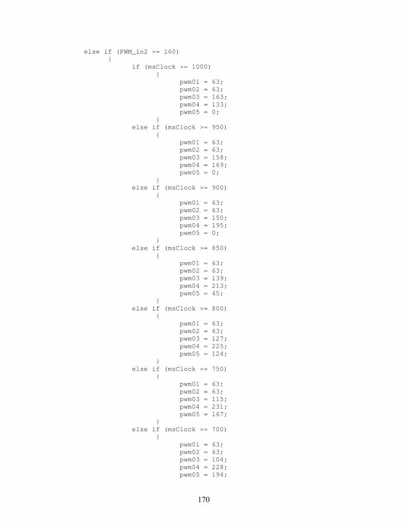
170
else if (PWM_in2 >= 160) if (msClock >= 1000) pwm01 = 63; pwm02 = 63; pwm03 = 163; pwm04 = 133; pwm05 = 0; else if (msClock >= 950) pwm01 = 63; pwm02 = 63; pwm03 = 158; pwm04 = 169; pwm05 = 0; else if (msClock >= 900) pwm01 = 63; pwm02 = 63; pwm03 = 150; pwm04 = 195; pwm05 = 0; else if (msClock >= 850) pwm01 = 63; pwm02 = 63; pwm03 = 139; pwm04 = 213; pwm05 = 45; else if (msClock >= 800) pwm01 = 63; pwm02 = 63; pwm03 = 127; pwm04 = 225; pwm05 = 124; else if (msClock >= 750) pwm01 = 63; pwm02 = 63; pwm03 = 115; pwm04 = 231; pwm05 = 167; else if (msClock >= 700) pwm01 = 63; pwm02 = 63; pwm03 = 104; pwm04 = 228; pwm05 = 194;

171
else if (msClock >= 650) pwm01 = 63; pwm02 = 63; pwm03 = 95; pwm04 = 216; pwm05 = 220; else if (msClock >= 600) pwm01 = 63; pwm02 = 63; pwm03 = 90; pwm04 = 194; pwm05 = 248; else if (msClock >= 550) pwm01 = 63; pwm02 = 63; pwm03 = 89; pwm04 = 161; pwm05 = 255; else if (msClock >= 500) pwm01 = 63; pwm02 = 63; pwm03 = 91; pwm04 = 121; pwm05 = 255; else if (msClock >= 450) pwm01 = 63; pwm02 = 63; pwm03 = 96; pwm04 = 85; pwm05 = 255; else if (msClock >= 400) pwm01 = 63; pwm02 = 63; pwm03 = 104; pwm04 = 59; pwm05 = 255; else if (msClock >= 350) pwm01 = 63; pwm02 = 63; pwm03 = 115; pwm04 = 41; pwm05 = 209;

172
else if (msClock >= 300) pwm01 = 63; pwm02 = 63; pwm03 = 127; pwm04 = 29; pwm05 = 130; else if (msClock >= 250) pwm01 = 63; pwm02 = 63; pwm03 = 139; pwm04 = 23; pwm05 = 87; else if (msClock >= 200) pwm01 = 63; pwm02 = 63; pwm03 = 150; pwm04 = 26; pwm05 = 60; else if (msClock >= 150) pwm01 = 63; pwm02 = 63; pwm03 = 159; pwm04 = 38; pwm05 = 34; else if (msClock >= 100) pwm01 = 63; pwm02 = 63; pwm03 = 164; pwm04 = 60; pwm05 = 6; else if (msClock >= 50) pwm01 = 63; pwm02 = 63; pwm03 = 165; pwm04 = 93; pwm05 = 0; else pwm01 = 63; pwm02 = 63; pwm03 = 163; pwm04 = 133; pwm05 = 0; /* holder for turning commands */

173
else if (PWM_in2 <= 94) if (msClock >= 1000) pwm01 = 191; pwm02 = 191; pwm03 = 163; pwm04 = 133; pwm05 = 0; else if (msClock >= 950) pwm01 = 191; pwm02 = 191; pwm03 = 158; pwm04 = 169; pwm05 = 0; else if (msClock >= 900) pwm01 = 191; pwm02 = 191; pwm03 = 150; pwm04 = 195; pwm05 = 0; else if (msClock >= 850) pwm01 = 191; pwm02 = 191; pwm03 = 139; pwm04 = 213; pwm05 = 45; else if (msClock >= 800) pwm01 = 191; pwm02 = 191; pwm03 = 127; pwm04 = 225; pwm05 = 124; else if (msClock >= 750) pwm01 = 191; pwm02 = 191; pwm03 = 115; pwm04 = 231; pwm05 = 167; else if (msClock >= 700) pwm01 = 191; pwm02 = 191; pwm03 = 104; pwm04 = 228; pwm05 = 194;

174
else if (msClock >= 650) pwm01 = 191; pwm02 = 191; pwm03 = 95; pwm04 = 216; pwm05 = 220; else if (msClock >= 600) pwm01 = 191; pwm02 = 191; pwm03 = 90; pwm04 = 194; pwm05 = 248; else if (msClock >= 550) pwm01 = 191; pwm02 = 191; pwm03 = 89; pwm04 = 161; pwm05 = 255; else if (msClock >= 500) pwm01 = 191; pwm02 = 191; pwm03 = 91; pwm04 = 121; pwm05 = 255; else if (msClock >= 450) pwm01 = 191; pwm02 = 191; pwm03 = 96; pwm04 = 85; pwm05 = 255; else if (msClock >= 400) pwm01 = 191; pwm02 = 191; pwm03 = 104; pwm04 = 59; pwm05 = 255; else if (msClock >= 350) pwm01 = 191; pwm02 = 191; pwm03 = 115; pwm04 = 41; pwm05 = 209;

175
else if (msClock >= 300) pwm01 = 191; pwm02 = 191; pwm03 = 127; pwm04 = 29; pwm05 = 130; else if (msClock >= 250) pwm01 = 191; pwm02 = 191; pwm03 = 139; pwm04 = 23; pwm05 = 87; else if (msClock >= 200) pwm01 = 191; pwm02 = 191; pwm03 = 150; pwm04 = 26; pwm05 = 60; else if (msClock >= 150) pwm01 = 191; pwm02 = 191; pwm03 = 159; pwm04 = 38; pwm05 = 34; else if (msClock >= 100) pwm01 = 191; pwm02 = 191; pwm03 = 164; pwm04 = 60; pwm05 = 6; else if (msClock >= 50) pwm01 = 191; pwm02 = 191; pwm03 = 165; pwm04 = 93; pwm05 = 0; else pwm01 = 191; pwm02 = 191; pwm03 = 163; pwm04 = 133; pwm05 = 0; /* holder for turning commands */

176
else pwm01 = 127; pwm02 = 127; pwm03 = 127; pwm04 = 127; pwm05 = 127; /* servos idle */ /*---------- Right Joystick Drive ------------------------------------------------------------------------ *-----------------------------------Successful Implementation 2010 – 06 – 19 : 1606 hrs------------------ * This code calls the Limit_Mix funtion to mix the Y and X axis on the right joystick for * control surface manipulation. * Right joystick up = Pitch control surfaces down (turn robot down) * Right joystick back = Pitch control surfaces up (turn robot up) * Right joystick right = Roll robot right * Right joystick left = Roll robot left * THIS SUBROUTINE MIXES PITCH AND ROLL INPUTS ON TRANSMITTER FOR DETERMINING SERVO STATES. * Connect the left fin servo to PWM OUT 6 on the robot controller. * Connect the right fin servo to PWM OUT 7 on the robot controller. */ pwm06 = Limit_Mix(2000 + PWM_in3 - PWM_in4 + 127); /* maps left fin servo to right joystick U/D & R/L */ if (pwm06 >= 148) pwm06 = 147; else if (pwm06 <= 108) pwm06 = 107; else pwm06 = pwm06; pwm07 = 255 - Limit_Mix(2000 + PWM_in3 + PWM_in4 - 127); /* "255-" because reverse rotation of left side */ if (pwm07 >= 148) pwm07 = 147; else if (pwm07 <= 108) pwm07 = 107; else
177
pwm07 = pwm07; /* ------ Other PWM OUTPUT Mapping ------------------------------------------------*/ pwm08 = PWM_in8; /* dummy, not used */ /* END Default_Routine(); */ /******************************************************************************/ /******************************************************************************/ /******************************************************************************/
B.16 user_routines.c ; Case 2, C1 = 0.5, C2 = 0.05 /******************************************************************************* * FILE NAME: user_routines.c <EDU VERSION> * * DESCRIPTION: * This file contains the default mappings of inputs * (like switches, joysticks, and buttons) to outputs on the EDU RC. * * USAGE: * You can either modify this file to fit your needs, or remove it from your * project and replace it with a modified copy. * *******************************************************************************/ #include "ifi_aliases.h" #include "ifi_default.h" #include "ifi_utilities.h" #include "user_routines.h" #include "printf_lib.h" #include "clock.h" // adds timer functionality /*** DEFINE USER VARIABLES AND INITIALIZE THEM HERE ***/ /* EXAMPLES: (see MPLAB C18 User's Guide, p.9 for all types) unsigned char wheel_revolutions = 0; (can vary from 0 to 255) unsigned int delay_count = 7; (can vary from 0 to 65,535) int angle_deviation = 142; (can vary from -32,768 to 32,767) unsigned long very_big_counter = 0; (can vary from 0 to 4,294,967,295) */

178
/******************************************************************************* * FUNCTION NAME: Limit_Switch_Max * PURPOSE: Sets a PWM value to neutral (127) if it exceeds 127 and the * limit switch is on. * CALLED FROM: this file * ARGUMENTS: * Argument Type IO Description * -------- ------------- -- ----------- * switch_state unsigned char I limit switch state * *input_value pointer O points to PWM byte value to be limited * RETURNS: void *******************************************************************************/ void Limit_Switch_Max(unsigned char switch_state, unsigned char *input_value) if (switch_state == CLOSED) if(*input_value > 127) *input_value = 127; /******************************************************************************* * FUNCTION NAME: Limit_Switch_Min * PURPOSE: Sets a PWM value to neutral (127) if it's less than 127 and the * limit switch is on. * CALLED FROM: this file * ARGUMENTS: * Argument Type IO Description * -------- ------------- -- ----------- * switch_state unsigned char I limit switch state * *input_value pointer O points to PWM byte value to be limited * RETURNS: void *******************************************************************************/ void Limit_Switch_Min(unsigned char switch_state, unsigned char *input_value) if (switch_state == CLOSED) if(*input_value < 127) *input_value = 127; /******************************************************************************* * FUNCTION NAME: Limit_Mix
179
* PURPOSE: Limits the mixed value for the joystick drive. 2000 is used as a mathematical * offset when this function is called so that the number presented to Limit_Mix * is not negative. The funtion removes the 2000 offset after operating. * CALLED FROM: Default_Routine, this file * ARGUMENTS: * Argument Type IO Description * -------- ---- -- ----------- * intermediate_value int I * RETURNS: unsigned char *******************************************************************************/ unsigned char Limit_Mix (int intermediate_value) static int limited_value; if (intermediate_value < 2000) limited_value = 2000; else if (intermediate_value > 2254) limited_value = 2254; else limited_value = intermediate_value; return (unsigned char) (limited_value - 2000); /******************************************************************************* * FUNCTION NAME: Setup_Who_Controls_Pwms * PURPOSE: Each parameter specifies what processor will control the pwm. * * CALLED FROM: User_Initialization * Argument Type IO Description * -------- ---- -- ----------- * pwmSpec1 int I USER/MASTER (defined in ifi_aliases.h) * pwmSpec2 int I USER/MASTER * pwmSpec3 int I USER/MASTER * pwmSpec4 int I USER/MASTER * pwmSpec5 int I USER/MASTER * pwmSpec6 int I USER/MASTER * pwmSpec7 int I USER/MASTER * pwmSpec8 int I USER/MASTER * RETURNS: void *******************************************************************************/ static void Setup_Who_Controls_Pwms(int pwmSpec1,int pwmSpec2,int pwmSpec3,int pwmSpec4,

180
int pwmSpec5,int pwmSpec6,int pwmSpec7,int pwmSpec8) txdata.pwm_mask = 0xFF; /* Default to master controlling all PWMs. */ if (pwmSpec1 == USER) /* If User controls PWM1 then clear bit0. */ txdata.pwm_mask &= 0xFE; /* same as txdata.pwm_mask = txdata.pwm_mask & 0xFE; */ if (pwmSpec2 == USER) /* If User controls PWM2 then clear bit1. */ txdata.pwm_mask &= 0xFD; if (pwmSpec3 == USER) /* If User controls PWM3 then clear bit2. */ txdata.pwm_mask &= 0xFB; if (pwmSpec4 == USER) /* If User controls PWM4 then clear bit3. */ txdata.pwm_mask &= 0xF7; if (pwmSpec5 == USER) /* If User controls PWM5 then clear bit4. */ txdata.pwm_mask &= 0xEF; if (pwmSpec6 == USER) /* If User controls PWM6 then clear bit5. */ txdata.pwm_mask &= 0xDF; if (pwmSpec7 == USER) /* If User controls PWM7 then clear bit6. */ txdata.pwm_mask &= 0xBF; if (pwmSpec8 == USER) /* If User controls PWM8 then clear bit7. */ txdata.pwm_mask &= 0x7F; /******************************************************************************* * FUNCTION NAME: User_Initialization * PURPOSE: This routine is called first (and only once) in the Main function. * You may modify and add to this function. * The primary purpose is to set up the DIGITAL IN/OUT - ANALOG IN * pins as analog inputs, digital inputs, and digital outputs. * CALLED FROM: main.c * ARGUMENTS: none * RETURNS: void *******************************************************************************/ void User_Initialization (void) rom const char *strptr = "IFI User Processor Initialized ..."; /* FIRST: Set up the pins you want to use as analog INPUTs. */ IO1 = IO2 = INPUT; /* Used for analog inputs. */ /* Note: IO1 = IO2 = IO3 = IO4 = INPUT; is the same as the following:

181
IO1 = INPUT; IO2 = INPUT; IO3 = INPUT; IO4 = INPUT; */ /* SECOND: Configure the number of analog channels. */ Set_Number_of_Analog_Channels(TWO_ANALOG); /* See ifi_aliases.h */ /* THIRD: Set up any extra digital inputs. */ /* The six INTERRUPTS are already digital inputs. */ /* If you need more then set them up here. */ /* IOxx = IOyy = INPUT; */ IO6 = IO8 = IO10 = INPUT; /* Used for limit switch inputs. */ IO12 = IO14 = IO16 = INPUT; /* Used for limit switch inputs. */ /* FOURTH: Set up the pins you want to use as digital OUTPUTs. */ IO3 = IO4 = OUTPUT; IO5 = IO7 = IO9 = OUTPUT; /* For connecting to adjacent limit switches. */ IO11 = IO13 = IO15 = OUTPUT; /* For connecting to adjacent limit switches. */ /* FIFTH: Initialize the values on the digital outputs. */ rc_dig_out03 = rc_dig_out04 = 0; rc_dig_out05 = rc_dig_out07 = rc_dig_out09 = 0; rc_dig_out11 = rc_dig_out13 = rc_dig_out15 = 0; /* SIXTH: Set your initial PWM values. Neutral is 127. */ pwm01 = pwm02 = pwm03 = pwm04 = pwm05 = pwm06 = pwm07 = pwm08 = 127; /* SEVENTH: Choose which processor will control which PWM outputs. */ Setup_Who_Controls_Pwms(MASTER,MASTER,MASTER,MASTER,MASTER,MASTER,MASTER,MASTER); /* EIGHTH: Set your PWM output type. Only applies if USER controls PWM 1, 2, 3, or 4. */ /* Choose from these parameters for PWM 1-4 respectively: */ /* IFI_PWM - Standard IFI PWM output generated with Generate_Pwms(...) */ /* USER_CCP - User can use PWM pin as digital I/O or CCP pin. */ Setup_PWM_Output_Type(IFI_PWM,IFI_PWM,IFI_PWM,IFI_PWM); /* Example: The following would generate a 40KHz PWM with a 50% duty cycle on the CCP2 pin (PWM OUT 1): CCP2CON = 0x3C; PR2 = 0xF9; CCPR2L = 0x7F; T2CON = 0; T2CONbits.TMR2ON = 1;

182
Setup_PWM_Output_Type(USER_CCP,IFI_PWM,IFI_PWM,IFI_PWM); */ /* Add any other user initialization code here. */ Initialize_Serial_Comms(); Initialize_Timer_2(); // initialize and start the clock Putdata(&txdata); /* DO NOT CHANGE! */ printf("%s\n", strptr); /* Optional - Print initialization message. */ User_Proc_Is_Ready(); /* DO NOT CHANGE! - last line of User_Initialization */ /******************************************************************************* * FUNCTION NAME: Process_Data_From_Master_uP * PURPOSE: Executes every 17ms when it gets new data from the master * microprocessor. * CALLED FROM: main.c * ARGUMENTS: none * RETURNS: void *******************************************************************************/ // Successful clock implimentation 2011 - 03 - 18 : 1536 hrs void Process_Data_From_Master_uP(void) Getdata(&rxdata); /* Get fresh data from the master microprocessor. */ Display_Time(); // located in clock.c Default_Routine(); /* See below. */ printf("PWM OUT 1 = %d, PWM OUT 2 = %d, PWM OUT 3 = %d, PWM OUT 4 = %d\n", (int)pwm01, (int)pwm02, (int)pwm03, (int)pwm04); printf("PWM OUT 5 = %d, PWM OUT 6 = %d, PWM OUT 7 = %d, PWM OUT 8 = %d\n", (int)pwm05, (int)pwm06, (int)pwm07, (int)pwm08); printf("PWM IN 1 = %d, PWM IN 2 = %d, PWM IN 3 = %d, PWM IN 4 = %d\n", (int)PWM_in1, (int)PWM_in2, (int)PWM_in3, (int)PWM_in4); /* printf("PWM IN 5 = %d, PWM IN 6 = %d, PWM IN 7 = %d, PWM IN 8 = %d\n", (int)PWM_in5, (int)PWM_in6, (int)PWM_in7, (int)PWM_in8); /* This snoops on the inputs being fed to the robot controller and the outputs being fed to the individual servos */ Putdata(&txdata); /* DO NOT CHANGE! */

183
/******************************************************************************* * FUNCTION NAME: Default_Routine * PURPOSE: Performs the default mappings of inputs to outputs for the * Robot Controller. * CALLED FROM: this file, Process_Data_From_Master_uP routine * ARGUMENTS: none * RETURNS: void *******************************************************************************/ void Default_Routine(void) /*---------- Left Joystick Drive ------------------------------------------------------------------------- *-------------------------------------------------Alpha Build 2010 – 06 – 26 : 1224 hrs------------------ *-------------------------------------------------------------------------------------------------------- * This code independently handles Y and X axis inputs on the left joystick for throttle * manipulation and robot turning. * Joystick forward = Robot forward * Joystick backward = Robot stop * Joystick right = Robot turns right * Joystick left = Robot turns left * Connect the first tail link servo to PWM OUT 1 on the robot controller. * Connect the second tail link servo to PWM OUT 2 on the robot controller. * Connect the third tail link servo to PWM OUT 3 on the robot controller. * Connect the fourth tail link servo to PWM OUT 4 on the robot controller. * Connect the fifth tail link servo to PWM OUT 5 on the robot controller. */ if (PWM_in1 >= 160) if (msClock >= 1000) pwm01 = 209; pwm02 = 146; pwm03 = 0; pwm04 = 62; pwm05 = 117; else if (msClock >= 950) pwm01 = 197; pwm02 = 190; pwm03 = 0; pwm04 = 4; pwm05 = 114;
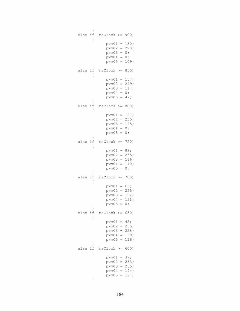
184
else if (msClock >= 900) pwm01 = 180; pwm02 = 220; pwm03 = 0; pwm04 = 0; pwm05 = 109; else if (msClock >= 850) pwm01 = 157; pwm02 = 249; pwm03 = 117; pwm04 = 0; pwm05 = 47; else if (msClock >= 800) pwm01 = 127; pwm02 = 255; pwm03 = 145; pwm04 = 0; pwm05 = 0; else if (msClock >= 750) pwm01 = 93; pwm02 = 255; pwm03 = 166; pwm04 = 110; pwm05 = 0; else if (msClock >= 700) pwm01 = 63; pwm02 = 255; pwm03 = 192; pwm04 = 131; pwm05 = 0; else if (msClock >= 650) pwm01 = 45; pwm02 = 255; pwm03 = 228; pwm04 = 139; pwm05 = 116; else if (msClock >= 600) pwm01 = 37; pwm02 = 253; pwm03 = 255; pwm04 = 144; pwm05 = 127;

185
else if (msClock >= 550) pwm01 = 38; pwm02 = 187; pwm03 = 255; pwm04 = 155; pwm05 = 133; else if (msClock >= 500) pwm01 = 45; pwm02 = 108; pwm03 = 255; pwm04 = 192; pwm05 = 137; else if (msClock >= 450) pwm01 = 57; pwm02 = 64; pwm03 = 255; pwm04 = 250; pwm05 = 140; else if (msClock >= 400) pwm01 = 74; pwm02 = 34; pwm03 = 255; pwm04 = 255; pwm05 = 145; else if (msClock >= 350) pwm01 = 97; pwm02 = 5; pwm03 = 137; pwm04 = 255; pwm05 = 207; else if (msClock >= 300) pwm01 = 127; pwm02 = 0; pwm03 = 109; pwm04 = 255; pwm05 = 255; else if (msClock >= 250) pwm01 = 161; pwm02 = 0; pwm03 = 88; pwm04 = 144; pwm05 = 255; else if (msClock >= 200)
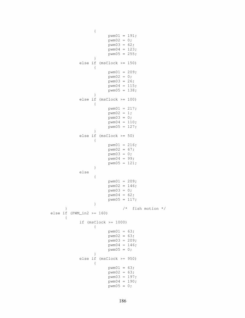
186
pwm01 = 191; pwm02 = 0; pwm03 = 62; pwm04 = 123; pwm05 = 255; else if (msClock >= 150) pwm01 = 209; pwm02 = 0; pwm03 = 26; pwm04 = 115; pwm05 = 138; else if (msClock >= 100) pwm01 = 217; pwm02 = 1; pwm03 = 0; pwm04 = 110; pwm05 = 127; else if (msClock >= 50) pwm01 = 216; pwm02 = 67; pwm03 = 0; pwm04 = 99; pwm05 = 121; else pwm01 = 209; pwm02 = 146; pwm03 = 0; pwm04 = 62; pwm05 = 117; /* fish motion */ else if (PWM_in2 >= 160) if (msClock >= 1000) pwm01 = 63; pwm02 = 63; pwm03 = 209; pwm04 = 146; pwm05 = 0; else if (msClock >= 950) pwm01 = 63; pwm02 = 63; pwm03 = 197; pwm04 = 190; pwm05 = 0;

187
else if (msClock >= 900) pwm01 = 63; pwm02 = 63; pwm03 = 180; pwm04 = 220; pwm05 = 0; else if (msClock >= 850) pwm01 = 63; pwm02 = 63; pwm03 = 157; pwm04 = 249; pwm05 = 117; else if (msClock >= 800) pwm01 = 63; pwm02 = 63; pwm03 = 127; pwm04 = 255; pwm05 = 145; else if (msClock >= 750) pwm01 = 63; pwm02 = 63; pwm03 = 93; pwm04 = 255; pwm05 = 166; else if (msClock >= 700) pwm01 = 63; pwm02 = 63; pwm03 = 63; pwm04 = 255; pwm05 = 192; else if (msClock >= 650) pwm01 = 63; pwm02 = 63; pwm03 = 45; pwm04 = 255; pwm05 = 228; else if (msClock >= 600) pwm01 = 63; pwm02 = 63; pwm03 = 37; pwm04 = 253; pwm05 = 255;

188
else if (msClock >= 550) pwm01 = 63; pwm02 = 63; pwm03 = 38; pwm04 = 187; pwm05 = 255; else if (msClock >= 500) pwm01 = 63; pwm02 = 63; pwm03 = 45; pwm04 = 108; pwm05 = 255; else if (msClock >= 450) pwm01 = 63; pwm02 = 63; pwm03 = 57; pwm04 = 64; pwm05 = 255; else if (msClock >= 400) pwm01 = 63; pwm02 = 63; pwm03 = 74; pwm04 = 34; pwm05 = 255; else if (msClock >= 350) pwm01 = 63; pwm02 = 63; pwm03 = 97; pwm04 = 5; pwm05 = 137; else if (msClock >= 300) pwm01 = 63; pwm02 = 63; pwm03 = 127; pwm04 = 0; pwm05 = 109; else if (msClock >= 250) pwm01 = 63; pwm02 = 63; pwm03 = 161; pwm04 = 0; pwm05 = 88; else if (msClock >= 200)

189
pwm01 = 63; pwm02 = 63; pwm03 = 191; pwm04 = 0; pwm05 = 62; else if (msClock >= 150) pwm01 = 63; pwm02 = 63; pwm03 = 209; pwm04 = 0; pwm05 = 26; else if (msClock >= 100) pwm01 = 63; pwm02 = 63; pwm03 = 217; pwm04 = 1; pwm05 = 0; else if (msClock >= 50) pwm01 = 63; pwm02 = 63; pwm03 = 216; pwm04 = 67; pwm05 = 0; else pwm01 = 63; pwm02 = 63; pwm03 = 209; pwm04 = 146; pwm05 = 0; /* holder for turning commands */ else if (PWM_in2 <= 94) if (msClock >= 1000) pwm01 = 191; pwm02 = 191; pwm03 = 209; pwm04 = 146; pwm05 = 0; else if (msClock >= 950) pwm01 = 191; pwm02 = 191; pwm03 = 197; pwm04 = 190; pwm05 = 0;

190
else if (msClock >= 900) pwm01 = 191; pwm02 = 191; pwm03 = 180; pwm04 = 220; pwm05 = 0; else if (msClock >= 850) pwm01 = 191; pwm02 = 191; pwm03 = 157; pwm04 = 249; pwm05 = 117; else if (msClock >= 800) pwm01 = 191; pwm02 = 191; pwm03 = 127; pwm04 = 255; pwm05 = 145; else if (msClock >= 750) pwm01 = 191; pwm02 = 191; pwm03 = 93; pwm04 = 255; pwm05 = 166; else if (msClock >= 700) pwm01 = 191; pwm02 = 191; pwm03 = 63; pwm04 = 255; pwm05 = 192; else if (msClock >= 650) pwm01 = 191; pwm02 = 191; pwm03 = 45; pwm04 = 255; pwm05 = 228; else if (msClock >= 600) pwm01 = 191; pwm02 = 191; pwm03 = 37; pwm04 = 253; pwm05 = 255;
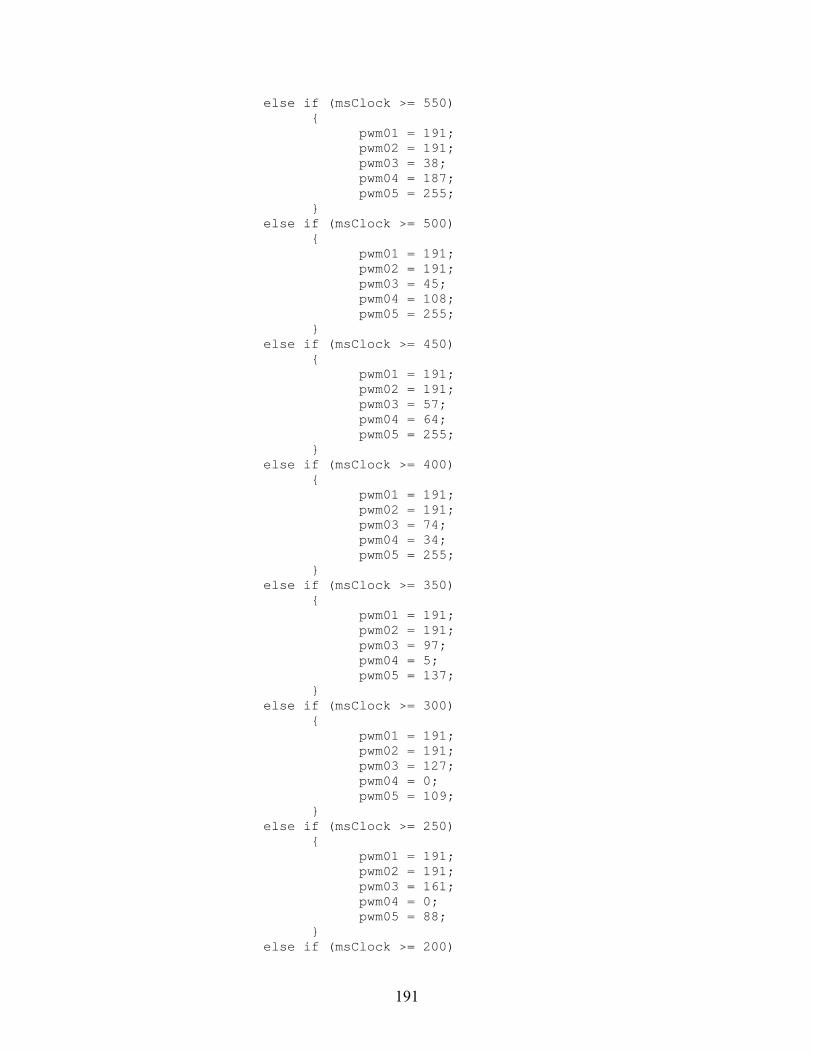
191
else if (msClock >= 550) pwm01 = 191; pwm02 = 191; pwm03 = 38; pwm04 = 187; pwm05 = 255; else if (msClock >= 500) pwm01 = 191; pwm02 = 191; pwm03 = 45; pwm04 = 108; pwm05 = 255; else if (msClock >= 450) pwm01 = 191; pwm02 = 191; pwm03 = 57; pwm04 = 64; pwm05 = 255; else if (msClock >= 400) pwm01 = 191; pwm02 = 191; pwm03 = 74; pwm04 = 34; pwm05 = 255; else if (msClock >= 350) pwm01 = 191; pwm02 = 191; pwm03 = 97; pwm04 = 5; pwm05 = 137; else if (msClock >= 300) pwm01 = 191; pwm02 = 191; pwm03 = 127; pwm04 = 0; pwm05 = 109; else if (msClock >= 250) pwm01 = 191; pwm02 = 191; pwm03 = 161; pwm04 = 0; pwm05 = 88; else if (msClock >= 200)

192
pwm01 = 191; pwm02 = 191; pwm03 = 191; pwm04 = 0; pwm05 = 62; else if (msClock >= 150) pwm01 = 191; pwm02 = 191; pwm03 = 209; pwm04 = 0; pwm05 = 26; else if (msClock >= 100) pwm01 = 191; pwm02 = 191; pwm03 = 217; pwm04 = 1; pwm05 = 0; else if (msClock >= 50) pwm01 = 191; pwm02 = 191; pwm03 = 216; pwm04 = 67; pwm05 = 0; else pwm01 = 191; pwm02 = 191; pwm03 = 209; pwm04 = 146; pwm05 = 0; /* holder for turning commands */ else pwm01 = 127; pwm02 = 127; pwm03 = 127; pwm04 = 127; pwm05 = 127; /* servos idle */ /*---------- Right Joystick Drive ------------------------------------------------------------------------ *-----------------------------------Successful Implementation 2010 – 06 – 19 : 1606 hrs------------------ * This code calls the Limit_Mix funtion to mix the Y and X axis on the right joystick for * control surface manipulation.

193
* Right joystick up = Pitch control surfaces down (turn robot down) * Right joystick back = Pitch control surfaces up (turn robot up) * Right joystick right = Roll robot right * Right joystick left = Roll robot left * THIS SUBROUTINE MIXES PITCH AND ROLL INPUTS ON TRANSMITTER FOR DETERMINING SERVO STATES. * Connect the left fin servo to PWM OUT 6 on the robot controller. * Connect the right fin servo to PWM OUT 7 on the robot controller. */ pwm06 = Limit_Mix(2000 + PWM_in3 - PWM_in4 + 127); /* maps left fin servo to right joystick U/D & R/L */ if (pwm06 >= 148) pwm06 = 147; else if (pwm06 <= 108) pwm06 = 107; else pwm06 = pwm06; pwm07 = 255 - Limit_Mix(2000 + PWM_in3 + PWM_in4 - 127); /* "255-" because reverse rotation of left side */ if (pwm07 >= 148) pwm07 = 147; else if (pwm07 <= 108) pwm07 = 107; else pwm07 = pwm07; /* ------ Other PWM OUTPUT Mapping ------------------------------------------------*/ pwm08 = PWM_in8; /* dummy, not used */ /* END Default_Routine(); */ /******************************************************************************/ /******************************************************************************/
194
/******************************************************************************/
B.17 user_routines.c ; Case 3, C1 = 0.1, C2 = 0.50 /******************************************************************************* * FILE NAME: user_routines.c <EDU VERSION> * * DESCRIPTION: * This file contains the default mappings of inputs * (like switches, joysticks, and buttons) to outputs on the EDU RC. * * USAGE: * You can either modify this file to fit your needs, or remove it from your * project and replace it with a modified copy. * *******************************************************************************/ #include "ifi_aliases.h" #include "ifi_default.h" #include "ifi_utilities.h" #include "user_routines.h" #include "printf_lib.h" #include "clock.h" // adds timer functionality /*** DEFINE USER VARIABLES AND INITIALIZE THEM HERE ***/ /* EXAMPLES: (see MPLAB C18 User's Guide, p.9 for all types) unsigned char wheel_revolutions = 0; (can vary from 0 to 255) unsigned int delay_count = 7; (can vary from 0 to 65,535) int angle_deviation = 142; (can vary from -32,768 to 32,767) unsigned long very_big_counter = 0; (can vary from 0 to 4,294,967,295) */ /******************************************************************************* * FUNCTION NAME: Limit_Switch_Max * PURPOSE: Sets a PWM value to neutral (127) if it exceeds 127 and the * limit switch is on. * CALLED FROM: this file * ARGUMENTS: * Argument Type IO Description * -------- ------------- -- ----------- * switch_state unsigned char I limit switch state * *input_value pointer O points to PWM byte value to be limited * RETURNS: void *******************************************************************************/

195
void Limit_Switch_Max(unsigned char switch_state, unsigned char *input_value) if (switch_state == CLOSED) if(*input_value > 127) *input_value = 127; /******************************************************************************* * FUNCTION NAME: Limit_Switch_Min * PURPOSE: Sets a PWM value to neutral (127) if it's less than 127 and the * limit switch is on. * CALLED FROM: this file * ARGUMENTS: * Argument Type IO Description * -------- ------------- -- ----------- * switch_state unsigned char I limit switch state * *input_value pointer O points to PWM byte value to be limited * RETURNS: void *******************************************************************************/ void Limit_Switch_Min(unsigned char switch_state, unsigned char *input_value) if (switch_state == CLOSED) if(*input_value < 127) *input_value = 127; /******************************************************************************* * FUNCTION NAME: Limit_Mix * PURPOSE: Limits the mixed value for the joystick drive. 2000 is used as a mathematical * offset when this function is called so that the number presented to Limit_Mix * is not negative. The funtion removes the 2000 offset after operating. * CALLED FROM: Default_Routine, this file * ARGUMENTS: * Argument Type IO Description * -------- ---- -- ----------- * intermediate_value int I * RETURNS: unsigned char *******************************************************************************/ unsigned char Limit_Mix (int intermediate_value)

196
static int limited_value; if (intermediate_value < 2000) limited_value = 2000; else if (intermediate_value > 2254) limited_value = 2254; else limited_value = intermediate_value; return (unsigned char) (limited_value - 2000); /******************************************************************************* * FUNCTION NAME: Setup_Who_Controls_Pwms * PURPOSE: Each parameter specifies what processor will control the pwm. * * CALLED FROM: User_Initialization * Argument Type IO Description * -------- ---- -- ----------- * pwmSpec1 int I USER/MASTER (defined in ifi_aliases.h) * pwmSpec2 int I USER/MASTER * pwmSpec3 int I USER/MASTER * pwmSpec4 int I USER/MASTER * pwmSpec5 int I USER/MASTER * pwmSpec6 int I USER/MASTER * pwmSpec7 int I USER/MASTER * pwmSpec8 int I USER/MASTER * RETURNS: void *******************************************************************************/ static void Setup_Who_Controls_Pwms(int pwmSpec1,int pwmSpec2,int pwmSpec3,int pwmSpec4, int pwmSpec5,int pwmSpec6,int pwmSpec7,int pwmSpec8) txdata.pwm_mask = 0xFF; /* Default to master controlling all PWMs. */ if (pwmSpec1 == USER) /* If User controls PWM1 then clear bit0. */ txdata.pwm_mask &= 0xFE; /* same as txdata.pwm_mask = txdata.pwm_mask & 0xFE; */ if (pwmSpec2 == USER) /* If User controls PWM2 then clear bit1. */ txdata.pwm_mask &= 0xFD; if (pwmSpec3 == USER) /* If User controls PWM3 then clear bit2. */ txdata.pwm_mask &= 0xFB;

197
if (pwmSpec4 == USER) /* If User controls PWM4 then clear bit3. */ txdata.pwm_mask &= 0xF7; if (pwmSpec5 == USER) /* If User controls PWM5 then clear bit4. */ txdata.pwm_mask &= 0xEF; if (pwmSpec6 == USER) /* If User controls PWM6 then clear bit5. */ txdata.pwm_mask &= 0xDF; if (pwmSpec7 == USER) /* If User controls PWM7 then clear bit6. */ txdata.pwm_mask &= 0xBF; if (pwmSpec8 == USER) /* If User controls PWM8 then clear bit7. */ txdata.pwm_mask &= 0x7F; /******************************************************************************* * FUNCTION NAME: User_Initialization * PURPOSE: This routine is called first (and only once) in the Main function. * You may modify and add to this function. * The primary purpose is to set up the DIGITAL IN/OUT - ANALOG IN * pins as analog inputs, digital inputs, and digital outputs. * CALLED FROM: main.c * ARGUMENTS: none * RETURNS: void *******************************************************************************/ void User_Initialization (void) rom const char *strptr = "IFI User Processor Initialized ..."; /* FIRST: Set up the pins you want to use as analog INPUTs. */ IO1 = IO2 = INPUT; /* Used for analog inputs. */ /* Note: IO1 = IO2 = IO3 = IO4 = INPUT; is the same as the following: IO1 = INPUT; IO2 = INPUT; IO3 = INPUT; IO4 = INPUT; */ /* SECOND: Configure the number of analog channels. */ Set_Number_of_Analog_Channels(TWO_ANALOG); /* See ifi_aliases.h */ /* THIRD: Set up any extra digital inputs. */ /* The six INTERRUPTS are already digital inputs. */ /* If you need more then set them up here. */ /* IOxx = IOyy = INPUT; */
198
IO6 = IO8 = IO10 = INPUT; /* Used for limit switch inputs. */ IO12 = IO14 = IO16 = INPUT; /* Used for limit switch inputs. */ /* FOURTH: Set up the pins you want to use as digital OUTPUTs. */ IO3 = IO4 = OUTPUT; IO5 = IO7 = IO9 = OUTPUT; /* For connecting to adjacent limit switches. */ IO11 = IO13 = IO15 = OUTPUT; /* For connecting to adjacent limit switches. */ /* FIFTH: Initialize the values on the digital outputs. */ rc_dig_out03 = rc_dig_out04 = 0; rc_dig_out05 = rc_dig_out07 = rc_dig_out09 = 0; rc_dig_out11 = rc_dig_out13 = rc_dig_out15 = 0; /* SIXTH: Set your initial PWM values. Neutral is 127. */ pwm01 = pwm02 = pwm03 = pwm04 = pwm05 = pwm06 = pwm07 = pwm08 = 127; /* SEVENTH: Choose which processor will control which PWM outputs. */ Setup_Who_Controls_Pwms(MASTER,MASTER,MASTER,MASTER,MASTER,MASTER,MASTER,MASTER); /* EIGHTH: Set your PWM output type. Only applies if USER controls PWM 1, 2, 3, or 4. */ /* Choose from these parameters for PWM 1-4 respectively: */ /* IFI_PWM - Standard IFI PWM output generated with Generate_Pwms(...) */ /* USER_CCP - User can use PWM pin as digital I/O or CCP pin. */ Setup_PWM_Output_Type(IFI_PWM,IFI_PWM,IFI_PWM,IFI_PWM); /* Example: The following would generate a 40KHz PWM with a 50% duty cycle on the CCP2 pin (PWM OUT 1): CCP2CON = 0x3C; PR2 = 0xF9; CCPR2L = 0x7F; T2CON = 0; T2CONbits.TMR2ON = 1; Setup_PWM_Output_Type(USER_CCP,IFI_PWM,IFI_PWM,IFI_PWM); */ /* Add any other user initialization code here. */ Initialize_Serial_Comms(); Initialize_Timer_2(); // initialize and start the clock Putdata(&txdata); /* DO NOT CHANGE! */ printf("%s\n", strptr); /* Optional - Print initialization message. */

199
User_Proc_Is_Ready(); /* DO NOT CHANGE! - last line of User_Initialization */ /******************************************************************************* * FUNCTION NAME: Process_Data_From_Master_uP * PURPOSE: Executes every 17ms when it gets new data from the master * microprocessor. * CALLED FROM: main.c * ARGUMENTS: none * RETURNS: void *******************************************************************************/ // Successful clock implimentation 2011 - 03 - 18 : 1536 hrs void Process_Data_From_Master_uP(void) Getdata(&rxdata); /* Get fresh data from the master microprocessor. */ Display_Time(); // located in clock.c Default_Routine(); /* See below. */ printf("PWM OUT 1 = %d, PWM OUT 2 = %d, PWM OUT 3 = %d, PWM OUT 4 = %d\n", (int)pwm01, (int)pwm02, (int)pwm03, (int)pwm04); printf("PWM OUT 5 = %d, PWM OUT 6 = %d, PWM OUT 7 = %d, PWM OUT 8 = %d\n", (int)pwm05, (int)pwm06, (int)pwm07, (int)pwm08); printf("PWM IN 1 = %d, PWM IN 2 = %d, PWM IN 3 = %d, PWM IN 4 = %d\n", (int)PWM_in1, (int)PWM_in2, (int)PWM_in3, (int)PWM_in4); /* printf("PWM IN 5 = %d, PWM IN 6 = %d, PWM IN 7 = %d, PWM IN 8 = %d\n", (int)PWM_in5, (int)PWM_in6, (int)PWM_in7, (int)PWM_in8); /* This snoops on the inputs being fed to the robot controller and the outputs being fed to the individual servos */ Putdata(&txdata); /* DO NOT CHANGE! */ /******************************************************************************* * FUNCTION NAME: Default_Routine * PURPOSE: Performs the default mappings of inputs to outputs for the * Robot Controller. * CALLED FROM: this file, Process_Data_From_Master_uP routine * ARGUMENTS: none * RETURNS: void *******************************************************************************/ void Default_Routine(void)

200
/*---------- Left Joystick Drive ------------------------------------------------------------------------- *-------------------------------------------------Alpha Build 2010 – 06 – 26 : 1224 hrs------------------ *-------------------------------------------------------------------------------------------------------- * This code independently handles Y and X axis inputs on the left joystick for throttle * manipulation and robot turning. * Joystick forward = Robot forward * Joystick backward = Robot stop * Joystick right = Robot turns right * Joystick left = Robot turns left * Connect the first tail link servo to PWM OUT 1 on the robot controller. * Connect the second tail link servo to PWM OUT 2 on the robot controller. * Connect the third tail link servo to PWM OUT 3 on the robot controller. * Connect the fourth tail link servo to PWM OUT 4 on the robot controller. * Connect the fifth tail link servo to PWM OUT 5 on the robot controller. */ if (PWM_in1 >= 160) if (msClock >= 1000) pwm01 = 248; pwm02 = 71; pwm03 = 0; pwm04 = 57; pwm05 = 116; else if (msClock >= 950) pwm01 = 234; pwm02 = 116; pwm03 = 0; pwm04 = 11; pwm05 = 114; else if (msClock >= 900) pwm01 = 213; pwm02 = 157; pwm03 = 0; pwm04 = 0; pwm05 = 111; else if (msClock >= 850) pwm01 = 182; pwm02 = 205; pwm03 = 124;

201
pwm04 = 0; pwm05 = 64; else if (msClock >= 800) pwm01 = 127; pwm02 = 255; pwm03 = 146; pwm04 = 0; pwm05 = 0; else if (msClock >= 750) pwm01 = 34; pwm02 = 255; pwm03 = 151; pwm04 = 129; pwm05 = 0; else if (msClock >= 700) pwm01 = 4; pwm02 = 255; pwm03 = 183; pwm04 = 142; pwm05 = 105; else if (msClock >= 650) pwm01 = 0; pwm02 = 255; pwm03 = 220; pwm04 = 148; pwm05 = 124; else if (msClock >= 600) pwm01 = 0; pwm02 = 255; pwm03 = 255; pwm04 = 155; pwm05 = 131; else if (msClock >= 550) pwm01 = 0; pwm02 = 241; pwm03 = 255; pwm04 = 168; pwm05 = 135; else if (msClock >= 500) pwm01 = 6; pwm02 = 183; pwm03 = 255; pwm04 = 197;

202
pwm05 = 138; else if (msClock >= 450) pwm01 = 20; pwm02 = 138; pwm03 = 255; pwm04 = 243; pwm05 = 140; else if (msClock >= 400) pwm01 = 41; pwm02 = 97; pwm03 = 255; pwm04 = 255; pwm05 = 143; else if (msClock >= 350) pwm01 = 72; pwm02 = 49; pwm03 = 130; pwm04 = 255; pwm05 = 190; else if (msClock >= 300) pwm01 = 127; pwm02 = 0; pwm03 = 108; pwm04 = 255; pwm05 = 255; else if (msClock >= 250) pwm01 = 220; pwm02 = 0; pwm03 = 103; pwm04 = 125; pwm05 = 255; else if (msClock >= 200) pwm01 = 250; pwm02 = 0; pwm03 = 71; pwm04 = 112; pwm05 = 149; else if (msClock >= 150) pwm01 = 255; pwm02 = 0; pwm03 = 34; pwm04 = 106; pwm05 = 130;

203
else if (msClock >= 100) pwm01 = 255; pwm02 = 0; pwm03 = 0; pwm04 = 99; pwm05 = 123; else if (msClock >= 50) pwm01 = 255; pwm02 = 13; pwm03 = 0; pwm04 = 86; pwm05 = 119; else pwm01 = 248; pwm02 = 71; pwm03 = 0; pwm04 = 57; pwm05 = 116; /* fish motion */ else if (PWM_in2 >= 160) if (msClock >= 1000) pwm01 = 63; pwm02 = 63; pwm03 = 248; pwm04 = 71; pwm05 = 0; else if (msClock >= 950) pwm01 = 63; pwm02 = 63; pwm03 = 234; pwm04 = 116; pwm05 = 0; else if (msClock >= 900) pwm01 = 63; pwm02 = 63; pwm03 = 213; pwm04 = 157; pwm05 = 0; else if (msClock >= 850) pwm01 = 63; pwm02 = 63; pwm03 = 182;

204
pwm04 = 205; pwm05 = 124; else if (msClock >= 800) pwm01 = 63; pwm02 = 63; pwm03 = 127; pwm04 = 255; pwm05 = 146; else if (msClock >= 750) pwm01 = 63; pwm02 = 63; pwm03 = 34; pwm04 = 255; pwm05 = 151; else if (msClock >= 700) pwm01 = 63; pwm02 = 63; pwm03 = 4; pwm04 = 255; pwm05 = 183; else if (msClock >= 650) pwm01 = 63; pwm02 = 63; pwm03 = 0; pwm04 = 255; pwm05 = 220; else if (msClock >= 600) pwm01 = 63; pwm02 = 63; pwm03 = 0; pwm04 = 255; pwm05 = 255; else if (msClock >= 550) pwm01 = 63; pwm02 = 63; pwm03 = 0; pwm04 = 241; pwm05 = 255; else if (msClock >= 500) pwm01 = 63; pwm02 = 63; pwm03 = 6; pwm04 = 183;

205
pwm05 = 255; else if (msClock >= 450) pwm01 = 63; pwm02 = 63; pwm03 = 20; pwm04 = 138; pwm05 = 255; else if (msClock >= 400) pwm01 = 63; pwm02 = 63; pwm03 = 41; pwm04 = 97; pwm05 = 255; else if (msClock >= 350) pwm01 = 63; pwm02 = 63; pwm03 = 72; pwm04 = 49; pwm05 = 130; else if (msClock >= 300) pwm01 = 63; pwm02 = 63; pwm03 = 127; pwm04 = 0; pwm05 = 108; else if (msClock >= 250) pwm01 = 63; pwm02 = 63; pwm03 = 220; pwm04 = 0; pwm05 = 103; else if (msClock >= 200) pwm01 = 63; pwm02 = 63; pwm03 = 250; pwm04 = 0; pwm05 = 71; else if (msClock >= 150) pwm01 = 63; pwm02 = 63; pwm03 = 255; pwm04 = 0; pwm05 = 34;

206
else if (msClock >= 100) pwm01 = 63; pwm02 = 63; pwm03 = 255; pwm04 = 0; pwm05 = 0; else if (msClock >= 50) pwm01 = 63; pwm02 = 63; pwm03 = 255; pwm04 = 13; pwm05 = 0; else pwm01 = 63; pwm02 = 63; pwm03 = 248; pwm04 = 71; pwm05 = 0; /* holder for turning commands */ else if (PWM_in2 <= 94) if (msClock >= 1000) pwm01 = 191; pwm02 = 191; pwm03 = 248; pwm04 = 71; pwm05 = 0; else if (msClock >= 950) pwm01 = 191; pwm02 = 191; pwm03 = 234; pwm04 = 116; pwm05 = 0; else if (msClock >= 900) pwm01 = 191; pwm02 = 191; pwm03 = 213; pwm04 = 157; pwm05 = 0; else if (msClock >= 850) pwm01 = 191; pwm02 = 191; pwm03 = 182;

207
pwm04 = 205; pwm05 = 124; else if (msClock >= 800) pwm01 = 191; pwm02 = 191; pwm03 = 127; pwm04 = 255; pwm05 = 146; else if (msClock >= 750) pwm01 = 191; pwm02 = 191; pwm03 = 34; pwm04 = 255; pwm05 = 151; else if (msClock >= 700) pwm01 = 191; pwm02 = 191; pwm03 = 4; pwm04 = 255; pwm05 = 183; else if (msClock >= 650) pwm01 = 191; pwm02 = 191; pwm03 = 0; pwm04 = 255; pwm05 = 220; else if (msClock >= 600) pwm01 = 191; pwm02 = 191; pwm03 = 0; pwm04 = 255; pwm05 = 255; else if (msClock >= 550) pwm01 = 191; pwm02 = 191; pwm03 = 0; pwm04 = 241; pwm05 = 255; else if (msClock >= 500) pwm01 = 191; pwm02 = 191; pwm03 = 6; pwm04 = 183;

208
pwm05 = 255; else if (msClock >= 450) pwm01 = 191; pwm02 = 191; pwm03 = 20; pwm04 = 138; pwm05 = 255; else if (msClock >= 400) pwm01 = 191; pwm02 = 191; pwm03 = 41; pwm04 = 97; pwm05 = 255; else if (msClock >= 350) pwm01 = 191; pwm02 = 191; pwm03 = 72; pwm04 = 49; pwm05 = 130; else if (msClock >= 300) pwm01 = 191; pwm02 = 191; pwm03 = 127; pwm04 = 0; pwm05 = 108; else if (msClock >= 250) pwm01 = 191; pwm02 = 191; pwm03 = 220; pwm04 = 0; pwm05 = 103; else if (msClock >= 200) pwm01 = 191; pwm02 = 191; pwm03 = 250; pwm04 = 0; pwm05 = 71; else if (msClock >= 150) pwm01 = 191; pwm02 = 191; pwm03 = 255; pwm04 = 0; pwm05 = 34;
209
else if (msClock >= 100) pwm01 = 191; pwm02 = 191; pwm03 = 255; pwm04 = 0; pwm05 = 0; else if (msClock >= 50) pwm01 = 191; pwm02 = 191; pwm03 = 255; pwm04 = 13; pwm05 = 0; else pwm01 = 191; pwm02 = 191; pwm03 = 248; pwm04 = 71; pwm05 = 0; /* holder for turning commands */ else pwm01 = 127; pwm02 = 127; pwm03 = 127; pwm04 = 127; pwm05 = 127; /* servos idle */ /*---------- Right Joystick Drive ------------------------------------------------------------------------ *-----------------------------------Successful Implementation 2010 – 06 – 19 : 1606 hrs------------------ * This code calls the Limit_Mix funtion to mix the Y and X axis on the right joystick for * control surface manipulation. * Right joystick up = Pitch control surfaces down (turn robot down) * Right joystick back = Pitch control surfaces up (turn robot up) * Right joystick right = Roll robot right * Right joystick left = Roll robot left * THIS SUBROUTINE MIXES PITCH AND ROLL INPUTS ON TRANSMITTER FOR DETERMINING SERVO STATES. * Connect the left fin servo to PWM OUT 6 on the robot controller. * Connect the right fin servo to PWM OUT 7 on the robot controller. */ pwm06 = Limit_Mix(2000 + PWM_in3 - PWM_in4 + 127); /* maps left fin servo to right joystick U/D & R/L */

210
if (pwm06 >= 148) pwm06 = 147; else if (pwm06 <= 108) pwm06 = 107; else pwm06 = pwm06; pwm07 = 255 - Limit_Mix(2000 + PWM_in3 + PWM_in4 - 127); /* "255-" because reverse rotation of left side */ if (pwm07 >= 148) pwm07 = 147; else if (pwm07 <= 108) pwm07 = 107; else pwm07 = pwm07; /* ------ Other PWM OUTPUT Mapping ------------------------------------------------*/ pwm08 = PWM_in8; /* dummy, not used */ /* END Default_Routine(); */ /******************************************************************************/ /******************************************************************************/ /******************************************************************************/