optimisation of the environmental scanning electron ... of the environmental scanning electron...
TRANSCRIPT

SCANNING VOL. 24, 305–313 (2002) Received: June 28, 2002© FAMS, Inc. Accepted: September 11, 2002
Optimisation of the Environmental Scanning Electron Microscope for Observation of Drying of Matt Water-Based Lacquers
C.P. ROYALL AND A.M. DONALD
Polymers and Colloids Group, Department of Physics, University of Cambridge, Cavendish Laboratory, Cambridge, U.K.
Summary: Environmental scanning electron microscopy(ESEM) modifies conventional SEM through the use of apartial gas pressure in the microscope specimen chamber.Like conventional SEM, it has the resolution to imagestructure on the submicron lengthscale, but can also toler-ate hydrated specimens if water vapour is used in the spec-imen chamber. This ability to image aqueous specimensleaves ESEM uniquely placed to study in situ drying inpolymer latexes. However, there are two key practical dif-ficulties associated with in situ drying. First, the size of thelatex particles: larger latex particles are typically around500 nm in diameter. Although ESEM can resolve structureon this lengthscale without difficulty, the magnification re-quired results in radiation damage of the specimen due tothe electron beam. This means that a given region can beimaged only once during film formation, so the evolutionof particular features cannot be followed. Second, thechange from ambient temperature and pressure to theESEM conditions of 7°C and 7.5 torr (100 Pa) can subjectthe specimen to a very high evaporation rate, which can dis-rupt film formation. The inclusion of a drop of water in thespecimen chamber is shown largely to alleviate this, en-abling successful imaging of film formation in the lacquer.Instead of the polymer latex itself, this work concentrateson a matting lacquer with silica inclusions. The silica mat-ting agent particles are 1–10 µm in size, allowing for alower magnification to be used, massively reducing spec-imen damage. Furthermore, the contrast during drying ismuch enhanced in the presence of silica. The images revealthe silica as bright regions against a darker background ofpolymer and water. Film formation shows the transition
from a uniform, featureless aqueous solution to a polymerfilm with silica particles present on the surface. The ap-pearance of individual silica particles can be followed.The particles are generally revealed quite early, after afew minutes of drying time. As film formation progresses,these same particles appear larger and more distinct. Fewnew particles are revealed at longer film formation times.
Key words: environmental scanning electron microscope,latex, drying, hydrated
PACS: 68.37.-d, 68.37.Hk
Introduction
Polymer latexes, the basis of most water-based lacquers,have been studied extensively (Keddie 1997). Although theprocess of film formation is not yet fully understood, fourstages have been proposed. The latex particles are initiallydispersed in an aqueous medium (stage I) before beingbrought into a densely packed array (stage II) (Keddie1997). Further evaporation is typically accompanied by de-formation of the spherical polymer particles to form a con-tinuous polymer film (stage III) (Brown 1956). Finally, thepolymer undergoes interdiffusion in which the boundariesbetween the latex particles are broken down (stage IV)(Keddie 1997). The transition from stage II to III requiresthat the particles are sufficiently viscoelastic to deform be-fore the water has evaporated. These latexes are termed filmforming. Latexes with harder particles that do not deformprior to the evaporation of water are called non-film form-ing (Keddie et al. 1996). Keddie termed these arrays of un-deformed latex particles stage II*. Here we focus on thestages of film formation associated with the removal ofwater, from stage I to III or II*.
The latex which forms the subject of this work has in-clusions of precipitated silica. This has significant practi-cal implications: the surface roughness imparted by the1–10 µm aggregate particles is on the lengthscale of visi-ble light, so specular reflection is much reduced (Gate etal. 1973). This combination of silica and latex is thereforeused extensively as a matting lacquer (Schneider 1994).
Environmental scanning electron microscopy (ESEM)is well-suited to observing in situ drying of the matt lac-
C.P. Royall was supported by an EPSRC (Engineering and physicalsciences research council) Studentship and a CASE award fromCrosfield Group.
Address for reprints:
Prof. A.M. DonaldPolymers and Colloids GroupDepartment of PhysicsUniversity of CambridgeCavendish LaboratoryMadingley RoadCambridge CB3 0HE, U.K.
quers for two main reasons: (1) It has the resolution toimage the silica particles which dominate the surface struc-ture, and (2) unlike conventional high-vacuum scanningelectron microscopy (SEM), it can tolerate insulating andeven hydrated specimens, such as the aqueous dispersionstudied here (Danilatos 1993). Careful control of experi-mental conditions allows in situ film formation to be fol-lowed (Keddie et al. 1996).
However, ESEM has two key limitations that havehampered previous attempts to follow drying: Specimendamage from the electron beam and specimen stabilisa-tion. Due to their high interfacial area, latexes are espe-cially susceptible to reactive species formed in water bythe electron beam (Royall et al. 2001, Talmon 1987).Keddie et al. (1996) imaged relatively large latex parti-cles of approximately 500 nm in diameter. AlthoughESEM is easily able to resolve this lengthscale, the mag-nification required was 4000×. The radiation damage re-sulting from this magnification prevented successiveimaging of the same area.
Radiation damage is much alleviated with the inclusionof silica. The larger size (1–10 µm) of the silica particlesrequires a magnification of only 800×. Since beam dam-age scales approximately with the square of magnifica-tion (Royall et al. 2001), the fivefold reduction in mag-nification relative to earlier work (Keddie et al. 1996)results in a very considerable decrease in radiation dam-age. If we assume that the electron beam penetratesaround 10µm into the specimen (Royall et al. 2001),there is a dose of approximately 12 kGy absorbed perimage in the irradiated region at 800×, compared with 310kGy at 5000×. In fact, scanning over a wider area allowssuccessive imaging of the same region, which can be fol-lowed in real time.
The second limitation results from the pumpdownprocess, where ambient air is replaced by the partial pres-sure of water vapour used when hydrated systems are im-aged by ESEM. This process can cause significant speci-men damage or at least alteration due to uncontrolled waterevaporation and boiling. This limitation is equally applic-able to the matt water-based lacquer examined here as tothe pure latexes examined by previous workers. The pump-down process has been examined by Cameron and Donald(1994), who suggested a means to minimise water evapo-ration. Here we explore how evaporation can be further re-duced with the introduction of a water source in the spec-imen chamber. The effect of this additional water sourceis considered using the model of Cameron and Donald(1994).
The images obtained by ESEM reveal silica particles asbright regions in a more uniform polymer/water back-ground. Computational analysis of these images providesa quantitative measure of the microstructure evolution dur-ing drying. This article first examines the ESEM pump-down process, and how it may be optimised for polymerlatexes. The optimised pumpdown is then applied to amatting water-based lacquer.
306 Scanning Vol. 24, 6 (2002)
Environmental Scanning Electron MicroscopePumpdown
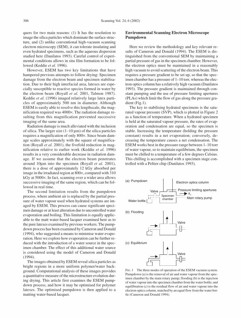
Here we review the methodology and key relevant re-sults of Cameron and Donald (1994). The ESEM is dis-tinguished from the conventional SEM by maintaining apartial pressure of gas in the specimen chamber. However,the electron optics must be maintained in a reasonablyhigh vacuum to avoid scattering of the electron beam. Thisrequires a pressure gradient to be set up, so that the spec-imen chamber has a pressure of 1–10 torr, whereas the elec-tron optics column has a relatively high vacuum (Danilatos1993). The pressure gradient is maintained through con-stant pumping and the use of pressure limiting apertures(PLAs) which limit the flow of gas along the pressure gra-dient (Fig.1).
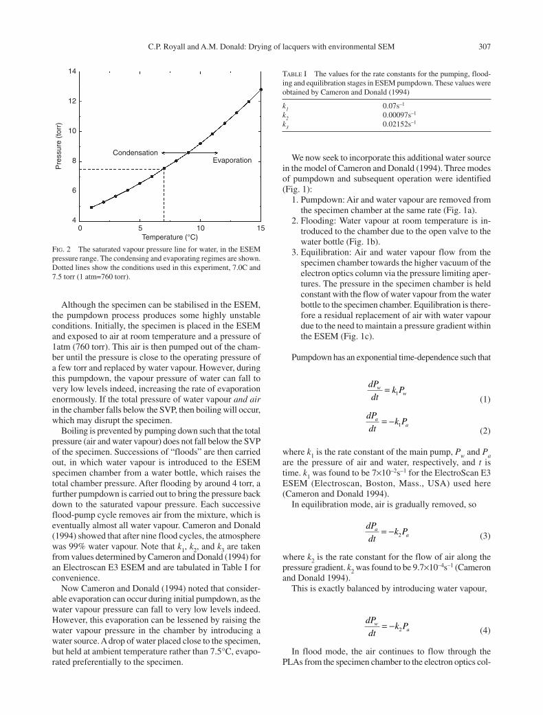
The key to stabilising hydrated specimens is the satu-rated vapour pressure (SVP), which is plotted in Figure 2as a function of temperature. When a hydrated specimenis held at the saturated vapour pressure, the rates of evap-oration and condensation are equal, so the specimen isstable. Increasing the temperature (holding the pressureconstant) results in a net evaporation; conversely, de-creasing the temperature causes a net condensation. TheESEM works best in the pressure range between 1–10 torrof water vapour, so to maintain equilibrium, the specimenmust be chilled to a temperature of a few degrees Celsius.This chilling is accomplished with a specimen stage con-trolled with a Peltier chip (Danilatos 1993).
FIG. 1 The three modes of operation of the ESEM vacuum system.Pumpdown (a) is the removal of air and water vapour from the spec-imen chamber by the main rotary pump; flooding (b) is the injectionof water vapour into the specimen chamber from the water bottle; andequilibration (c) is the residual flow of air and water vapour into theelectron optics column, matched by an equal flow from the water bot-tle (Cameron and Donald 1994).
Electron optics column
Pressure limiting aperturesValve
Valve
Valve
Water bottleMain rotary pumpk1Specimen
chamber
(a): Pumpdown
(b): Flooding
(c): Equilibrium
Although the specimen can be stabilised in the ESEM,the pumpdown process produces some highly unstableconditions. Initially, the specimen is placed in the ESEMand exposed to air at room temperature and a pressure of1atm (760 torr). This air is then pumped out of the cham-ber until the pressure is close to the operating pressure ofa few torr and replaced by water vapour. However, duringthis pumpdown, the vapour pressure of water can fall tovery low levels indeed, increasing the rate of evaporationenormously. If the total pressure of water vapour and airin the chamber falls below the SVP, then boiling will occur,which may disrupt the specimen.
Boiling is prevented by pumping down such that the totalpressure (air and water vapour) does not fall below the SVPof the specimen. Successions of “floods” are then carriedout, in which water vapour is introduced to the ESEMspecimen chamber from a water bottle, which raises thetotal chamber pressure. After flooding by around 4 torr, afurther pumpdown is carried out to bring the pressure backdown to the saturated vapour pressure. Each successiveflood-pump cycle removes air from the mixture, which iseventually almost all water vapour. Cameron and Donald(1994) showed that after nine flood cycles, the atmospherewas 99% water vapour. Note that k1, k2, and k3 are takenfrom values determined by Cameron and Donald (1994) foran Electroscan E3 ESEM and are tabulated in Table I forconvenience.
Now Cameron and Donald (1994) noted that consider-able evaporation can occur during initial pumpdown, as thewater vapour pressure can fall to very low levels indeed.However, this evaporation can be lessened by raising thewater vapour pressure in the chamber by introducing awater source. A drop of water placed close to the specimen,but held at ambient temperature rather than 7.5°C, evapo-rated preferentially to the specimen.
C.P. Royall and A.M. Donald: Drying of lacquers with environmental SEM 307
We now seek to incorporate this additional water sourcein the model of Cameron and Donald (1994). Three modesof pumpdown and subsequent operation were identified(Fig. 1):
1. Pumpdown: Air and water vapour are removed fromthe specimen chamber at the same rate (Fig. 1a).
2. Flooding: Water vapour at room temperature is in-troduced to the chamber due to the open valve to thewater bottle (Fig. 1b).
3. Equilibration: Air and water vapour flow from thespecimen chamber towards the higher vacuum of theelectron optics column via the pressure limiting aper-tures. The pressure in the specimen chamber is heldconstant with the flow of water vapour from the waterbottle to the specimen chamber. Equilibration is there-fore a residual replacement of air with water vapourdue to the need to maintain a pressure gradient withinthe ESEM (Fig. 1c).
Pumpdown has an exponential time-dependence such that
(1)
(2)
where k1 is the rate constant of the main pump, Pw and Paare the pressure of air and water, respectively, and t istime. k1 was found to be 7×10⁻²s–1 for the ElectroScan E3ESEM (Electroscan, Boston, Mass., USA) used here(Cameron and Donald 1994).
In equilibration mode, air is gradually removed, so
(3)
where k2 is the rate constant for the flow of air along thepressure gradient. k2 was found to be 9.7×10⁻⁴s–1 (Cameronand Donald 1994).
This is exactly balanced by introducing water vapour,
(4)
In flood mode, the air continues to flow through thePLAs from the specimen chamber to the electron optics col-
dP
dtk Pw
a= − 2
dP
dtk Pa
a= − 2
dP
dtk Pa
a= − 1
dP
dtk Pw
w= 1
FIG. 2 The saturated vapour pressure line for water, in the ESEMpressure range. The condensing and evaporating regimes are shown.Dotted lines show the conditions used in this experiment, 7.0C and7.5 torr (1 atm=760 torr).
TABLE I The values for the rate constants for the pumping, flood-ing and equilibration stages in ESEM pumpdown. These values wereobtained by Cameron and Donald (1994)
k1 0.07s–1
k2 0.00097s–1
k3 0.02152s–1
14
12
10
8
6
4
Pre
ssur
e (t
orr)
0 5
CondensationEvaporation
10 15Temperature (°C)
umn, so Eq. (3) still holds. The water vapour pressure isgiven by
(5)
k3 (=2.152×10⁻²s–1) is the rate constant for water vapour in-flow from the water source bottle, X(Tr) is the saturatedvapour pressure for water, at room temperature (Tr) as thebottle is not chilled (Cameron and Donald 1994).
Note that k1, k2, and k3 are taken from values deter-mined by Cameron and Donald (1994) for an ElectroScanE3 ESEM, which would not be identical to the ElectroScan2010 used in this work. However, measuring these valuesfor the ElectroScan 2010 was not considered to be appro-priate or necessary: the parameters vary considerably overtime, requiring measurement before each experiment,which was not practical. Furthermore, the conclusionsdrawn from this section are equally applicable to the Elec-troScan E3 and 2010 ESEMs and are not hugely sensitiveto the exact values of k1, k2, and k3.
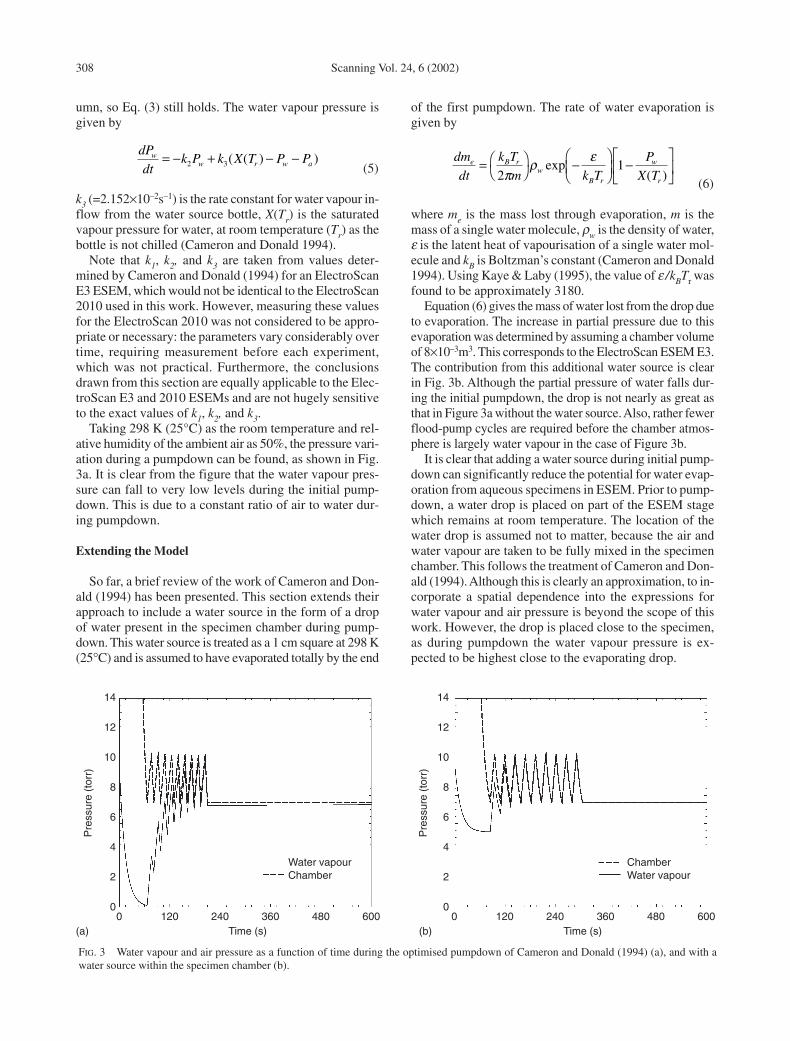
Taking 298 K (25°C) as the room temperature and rel-ative humidity of the ambient air as 50%, the pressure vari-ation during a pumpdown can be found, as shown in Fig.3a. It is clear from the figure that the water vapour pres-sure can fall to very low levels during the initial pump-down. This is due to a constant ratio of air to water dur-ing pumpdown.
Extending the Model
So far, a brief review of the work of Cameron and Don-ald (1994) has been presented. This section extends theirapproach to include a water source in the form of a dropof water present in the specimen chamber during pump-down. This water source is treated as a 1 cm square at 298 K(25°C) and is assumed to have evaporated totally by the end
dP
dtk P k X T P Pw
w r w a= − + − −2 3( ( ) )
308 Scanning Vol. 24, 6 (2002)
of the first pumpdown. The rate of water evaporation isgiven by
(6)
where me is the mass lost through evaporation, m is themass of a single water molecule, ρw is the density of water,ε is the latent heat of vapourisation of a single water mol-ecule and kB is Boltzman’s constant (Cameron and Donald1994). Using Kaye & Laby (1995), the value of ε /kBTr wasfound to be approximately 3180.
Equation (6) gives the mass of water lost from the drop dueto evaporation. The increase in partial pressure due to thisevaporation was determined by assuming a chamber volumeof 8×10⁻³m3. This corresponds to the ElectroScan ESEM E3.The contribution from this additional water source is clearin Fig. 3b. Although the partial pressure of water falls dur-ing the initial pumpdown, the drop is not nearly as great asthat in Figure 3a without the water source. Also, rather fewerflood-pump cycles are required before the chamber atmos-phere is largely water vapour in the case of Figure 3b.
It is clear that adding a water source during initial pump-down can significantly reduce the potential for water evap-oration from aqueous specimens in ESEM. Prior to pump-down, a water drop is placed on part of the ESEM stagewhich remains at room temperature. The location of thewater drop is assumed not to matter, because the air andwater vapour are taken to be fully mixed in the specimenchamber. This follows the treatment of Cameron and Don-ald (1994). Although this is clearly an approximation, to in-corporate a spatial dependence into the expressions forwater vapour and air pressure is beyond the scope of thiswork. However, the drop is placed close to the specimen,as during pumpdown the water vapour pressure is ex-pected to be highest close to the evaporating drop.
dm
dt
k T
m k T
P
X Te B r
wB r
w
r
=
−
−
2
1π
ρ εexp
( )
FIG. 3 Water vapour and air pressure as a function of time during the optimised pumpdown of Cameron and Donald (1994) (a), and with awater source within the specimen chamber (b).
14
12
10
8
6
4
2
0
14
12
10
8
6
4
2
00 120 240 360 480
Time (s)(a) (b)
Water vapourChamber
ChamberWater vapour
Pre
ssur
e (t
orr)
Pre
ssur
e (t
orr)
600 0 120 240 360 480Time (s)
600
Environmental Scanning Electron Microscope Contrast
Observed contrast in ESEM comes from two routes,backscattered and secondary electrons. Backscattered elec-trons are incident electrons, which have been elasticallyscattered strongly in the specimen so that they are ejectedand thus contribute to the signal. Incident electrons inter-act more strongly with the larger atomic nuclei, so back-scattered electrons are sensitive to atomic number (Gold-stein 1992). In this case, a bright signal is associated withthe relatively high atomic number of silicon in the silicaparticles with respect to the polymer film.
Secondary electrons are produced by ionisation eventsin the sample. Secondary electrons are comparatively lowenergy and hence have a rather small escape depth, of theorder of a few nanometers. Since the penetration of inci-dent beam electrons is much greater, the bulk of secondaryelectrons are produced deeper inside the specimen and re-absorbed. A sloping surface increases the chance of escapefor secondary electrons at greater depths, so the signal isincreased, giving rise to topographic contrast (Goldstein etal. 1992). Since surface roughness is related to the presenceof silica at the surface (Schneider 1994), a strong sec-ondary electron signal from regions of surface silica is ex-pected.
A further source of secondary electron contrast is asso-ciated with the energy gap between conducting and valenceelectrons in the specimen (band gap). Secondary electronscan travel further before reabsorption in materials withwider energy gaps, which increases the probability of es-cape. The signal, therefore, is stronger from materials withwider band gaps (Stokes et al. 1998). For the specimensstudied here, in the early stages of film formation, morewater is present, which has a larger band gap than the finalpolymer film, and so the signal is expected to be strongerto begin with.
Materials and Methods
In this work an ElectroScan 2010 ESEM was used. Thebeam energy was 8 keV; this relatively low value was cho-sen because lower energies minimise specimen damage(Royall et al. 2001). Other experimental parameters werechosen to promote film formation, in particular specimentemperature and chamber pressure. The Tg of the latexused was quoted as 80°C (Allied Colloids). Although thedeformation stage of film formation (stages II–III) is pro-moted by the addition of plasticisers, it was desirable toraise the specimen temperature as much as possible to beclose to room temperature, where the latex is film forming,compared with typical ESEM specimen temperatures of3°C (O’Dowd et al. 1994).
In practice, the specimen temperature chosen was lim-ited by the chamber pressure. At pressures above 5 torr, theESEM signal falls off (Fletcher 1997), and a chamber pres-sure of 7.5 torr was chosen as the highest pressure at which
C.P. Royall and A.M. Donald: Drying of lacquers with environmental SEM 309
the ESEM produced images of sufficient quality. Since thehydrated specimen must be kept close to saturated vapourpressure, the specimen temperature corresponding to 7.5torr was 7.0°C. This was the highest temperature at whichin situ film formation could be followed.
The specimen was chilled to 6.5°C during pumpdownto prevent any boiling. A small amount of condensation oc-curred as a result of this temperature suppression, whichwas removed by raising the specimen temperature at arate of 0.1°C min–1. The evaporation of water in this wayalso initiated film formation, and the temperature was in-creased until silica could be discerned on the surface. Filmformation was then recorded in a series of image scans.This method was chosen over varying the pressure, whichcould equivalently have been used to initiate film forma-t i o n ,because temperature was easier to control precisely on theElectroScan 2010 ESEM.
Image Analysis
The image analysis technique employed has been de-tailed previously (Royall 2000, Royall and Donald 2001),and is recapped here. The aim is to isolate the pixels in theESEM image that correspond to silica. Each pixel is there-fore chosen as either “silica” or “background,” accordingto certain criteria.
Although silica appears bright, due to small imaging in-stabilities in ESEM (e.g., fluctuations in electron beam in-tensity) simply selecting bright pixels tends not to producereliable results (Royall 2000). Instead the change in bright-ness associated with silica is used to detect silica particles.The Sobel operator (S) (Russ 1995) is used to quantify thechange in brightness,
(7)
where I(x,y) is the brightness of the pixel at (x,y). If theSobel operator had a value of >15, the corresponding pixelwas taken to be silica. The Sobel operator tends to find theedges of the silica particles, missing a few very bright pix-els in the centre. These were identified with a brightnessthreshold. The brightness threshold required that the pixelhad a brightness value >245 on a scale from 0–255. If ei-ther or both criteria were satisfied, then the pixel was takento be silica. By dividing the silica pixels by the total, thesilica surface fraction can be obtained as a function of dry-ing time. The gradient threshold is determined by requir-ing that an image with no visible silica yields only a verysmall fraction of pixels, around 10–5 which can be identi-fied as silica. In this way, the noise in the system was elim-inated (Royall 2000). The brightness threshold was simplychosen to be close to, but less than, 255.
Following thresholding, the image has two types of
S II
x
I
y( ) =
+
∂∂
∂∂
2 2
pixel, corresponding to the silica or the polymer/waterbackground. The silica pixels tend to be grouped in clus-ters, corresponding to the silica particles. These clusters canbe counted and sized (Royall 2000). Thus the number ofclusters can be followed during film formation. A furtherrequirement is to ignore isolated bright pixels, which areassociated with noise (Pawley 1995, Russ 1995). This isachieved by requiring that each cluster of pixels must be>10 to be treated as silica. The silica surface fraction andcluster count is then adjusted accordingly.
The image processing software used in this work waswritten by the authors in the C programming language andrun on a unix workstation (Royall 2000).
Specimen Preparation
The details of specimen preparation have been presentedelsewhere (Royall and Donald 2001). Here the main pointsonly are noted. The lacquer was based on a polybutyl-methacrylate (PBMA) latex with a diameter of 80 nm (Al-lied Colloids). A variety of additives were used, includinga defoamer, coalescing aid, and rheology modifier. Mostimportant, silica was incorporated at 2.5% by weight.
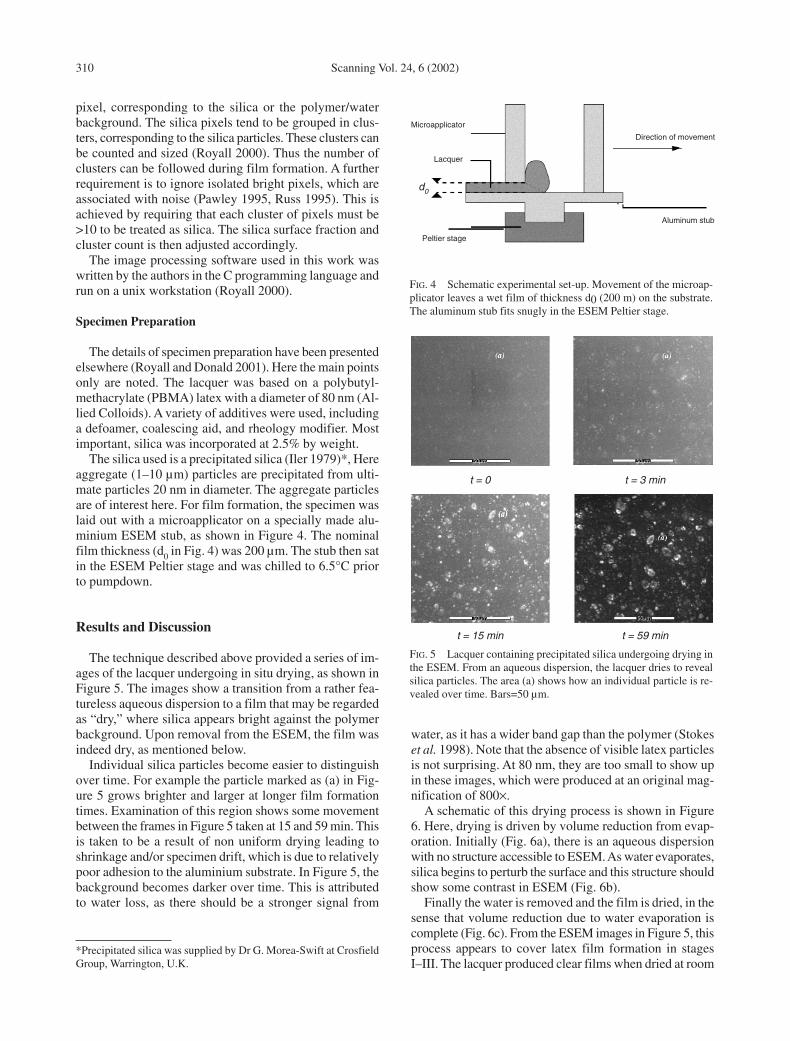
The silica used is a precipitated silica (Iler 1979)*, Hereaggregate (1–10 µm) particles are precipitated from ulti-mate particles 20 nm in diameter. The aggregate particlesare of interest here. For film formation, the specimen waslaid out with a microapplicator on a specially made alu-minium ESEM stub, as shown in Figure 4. The nominalfilm thickness (d0 in Fig. 4) was 200 µm. The stub then satin the ESEM Peltier stage and was chilled to 6.5°C priorto pumpdown.
Results and Discussion
The technique described above provided a series of im-ages of the lacquer undergoing in situ drying, as shown inFigure 5. The images show a transition from a rather fea-tureless aqueous dispersion to a film that may be regardedas “dry,” where silica appears bright against the polymerbackground. Upon removal from the ESEM, the film wasindeed dry, as mentioned below.
Individual silica particles become easier to distinguishover time. For example the particle marked as (a) in Fig-ure 5 grows brighter and larger at longer film formationtimes. Examination of this region shows some movementbetween the frames in Figure 5 taken at 15 and 59 min. Thisis taken to be a result of non uniform drying leading toshrinkage and/or specimen drift, which is due to relativelypoor adhesion to the aluminium substrate. In Figure 5, thebackground becomes darker over time. This is attributedto water loss, as there should be a stronger signal from
310 Scanning Vol. 24, 6 (2002)
FIG. 4 Schematic experimental set-up. Movement of the microap-plicator leaves a wet film of thickness d0 (200 m) on the substrate.The aluminum stub fits snugly in the ESEM Peltier stage.
FIG. 5 Lacquer containing precipitated silica undergoing drying inthe ESEM. From an aqueous dispersion, the lacquer dries to revealsilica particles. The area (a) shows how an individual particle is re-vealed over time. Bars=50 µm.
*Precipitated silica was supplied by Dr G. Morea-Swift at CrosfieldGroup, Warrington, U.K.
t = 0 t = 3 min
Direction of movement
Aluminum stub
Peltier stage
Lacquer
Microapplicator
t = 15 min t = 59 min
d0
water, as it has a wider band gap than the polymer (Stokeset al. 1998). Note that the absence of visible latex particlesis not surprising. At 80 nm, they are too small to show upin these images, which were produced at an original mag-nification of 800×.
A schematic of this drying process is shown in Figure6. Here, drying is driven by volume reduction from evap-oration. Initially (Fig. 6a), there is an aqueous dispersionwith no structure accessible to ESEM. As water evaporates,silica begins to perturb the surface and this structure shouldshow some contrast in ESEM (Fig. 6b).
Finally the water is removed and the film is dried, in thesense that volume reduction due to water evaporation iscomplete (Fig. 6c). From the ESEM images in Figure 5, thisprocess appears to cover latex film formation in stagesI–III. The lacquer produced clear films when dried at room
50µm 50µm
50µm 50µm

temperature, which is indicative of stages III–IV (Keddie1997, O’Dowd et al. 1994). However, the films producedin the ESEM were white, which suggests film formationonly to stage II* (Keddie 1997). It seems that the temper-ature suppression to 7°C meant that the latex was too rigidto deform to stage III. In other words, it behaved as a non-film-forming latex at 7°C. Nonetheless, ESEM images offilm dried in situ show exactly the same features as thoseof films dried at room temperature, as can be seen from Fig-ure 7. This is unsurprising, given that here we are fo-cussing on the silica, not the latex particles. At 80 nm indiameter, the latex particles are too small to be revealed,regardless of whether or not they have deformed. Clearlya latex which is film forming at 7°C should be entirely in-sensitive to whether it is dried in situ or at room tempera-ture. However, at the lengthscales used, here the techniqueis insensitive to whether or not the latex is film forming.
Numerical Analysis
The fraction of pixels identified as silica (silica surfacefraction) is plotted in Figure 8 as a function of time. Thetime is taken as zero when the silica can first be seen onthe surface. There is an increase in silica surface fractionwith time, as would be expected from the images, exceptat around a time of 30 min. This drop is assumed to be dueto chance specimen movement, which has already beennoted from Figure 5.
The number of distinct clusters is shown as a function
C.P. Royall and A.M. Donald: Drying of lacquers with environmental SEM 311
of time in Figure 9. Like the silica surface fraction, the clus-ter count increases with time, although the count increasesrather more quickly than the surface fraction. In otherwords, the silica particles are identified on the surfacequite early, after around 5 min. Further drying revealsmore of these same silica particles, so although the num-ber of clusters is roughly constant, the silica surface frac-tion increases for drying times of up to 20 min as more ofthe same particles are revealed.
Although it is roughly constant, the cluster count fluc-tuates and is highest at around 12 min. This is taken to bedue to the difference between silica particles and clusters.A cluster is a group of neighbouring white pixels, whereasa silica particle is a real object. Each silica particle can pro-duce more than one cluster, especially at short dryingtimes, as might be expected from the region marked (*) inFigure 6b. Alternatively, at longer drying times, several sil-ica particles form only one cluster, such as that marked as
FIG. 6 Schematic of silica in aqueous lacquer during drying. StageI of latex film formation corresponds to (a), where the silica is dis-persed throughout the aqueous latex suspension; (b) and (c) are theresults of stage II and III (or II*) of latex film formation, respectively.
FIG. 7 Environmental scanning electron microscope image of filmdried at room temperature. Exactly the same structure is shown as thatfor a specimen dried in situ.
FIG. 8 Silica surface fraction as a function of drying time, which istaken from the first appearance of silica in the ESEM images.
0.5
0.4
0.3
0.2
0.1
00 10 20
Time (min)
Sili
ca s
urfa
ce fr
actio
n
30 40 50 60
(a)
(b)
(c)
20 µm

312 Scanning Vol. 24, 6 (2002)
with continuous water loss. Peaks of particles are seenfirst, before the remainder is revealed by further volumeloss from water evaporation.
One possible improvement to the pumpdown processwould be partially to open the valve to the ESEM water bot-tle during initial pumpdown. With monitoring of the k1–3parameters and careful control of the water inflow, it shouldbe possible to maintain saturated vapour pressure through-out pumpdown, which would eliminate specimen conden-sation and evaporation during pumpdown.
This technique could be applied to other systems: anylatex with hard inclusions should be accessible to thismethodology. In particular, the silica could be substitutedwith pigment for analysis of pigmented lacquers. Othersystems that could be studied include sunscreen (where thetitanium dioxide screening agent would provide consid-erable atomic number contrast), lipstick, and other cos-metics. However, the effects of temperature suppressionto around 7°C should not be overlooked. This tends to in-hibit film formation, such that a film-forming latex atroom temperature may not proceed beyond stage II* at7°C, as is the case in this work. However, the features ofinterest are not strongly sensitive to latex deformation, sothe lack of latex deformation has little effect on the imagesrecorded.
Environmental scanning electron microscopy is not lim-ited to water-based systems. Oil-based systems can also beimaged (Stokes et al. 1998). Here, the technique is rathersimpler; due to their typically low vapour pressure, oil-based specimens are stable in the ESEM, so there is no needto maintain the saturated water vapour pressure in thespecimen chamber. Oil-based lacquers can therefore be im-aged at room temperature. Like water-based systems, someform of hard inclusion would be desirable to promote con-trast.
Acknowledgments
The authors would like to thank the Engineering andPhysical Sciences Research Council and Crosfield Groupfor funding, and in particular Drs G. Morea-Swift of Cros-fields, B.L. Thiel for ESEM pumpdown help, and Drs. G.Soga and O.M. Astley for discussions relating to imageanalysis.
References
Allied Colloids, Coatings and Specialities Division, Allied ColloidsLtd, Bradford, West Yorkshire, UK. Glascol C47, technical andprocessing data
Brown GL: Formation of films from polymer dispersions. J PolymerSci, 12, 423–434 (1956)
Cameron RE, Donald AM: Minimizing sample evaporation in the en-vironmental scanning electron microscope. J Microsc, 173,227–237 (1994)
Danilatos G: Introduction to the ESEM instrument. Microsc ResTech 25, 354–361 (1993)
FIG. 9 Cluster count as a function of drying time.
(**) in Figure 6c. The numerical results support the mechanism illustrated
in Figure 6. The silica particles are viewed as embeddedin a polymer/water matrix. Initially (Fig. 6a), silica is be-neath the surface, presumably held by surface tension ofthe aqueous phase. Evaporation will tend to bring the sur-face of the increasingly concentrated dispersion down.During this period, there is competition between surfacetension (which tends to keep silica below the surface) andthe material below the top layer of silica particles, whichtends to resist further compression.
By the time stage II of latex film formation is reached,the lower material resists compression sufficiently that thesilica particles break through the water/latex surface andsilica is visible on the surface (Fig. 6b). Further evapora-tion results in a receding surface. However the silica par-ticles are now held up by the material below them. As thesurface recedes, more and more of this top layer is exposed,so the particles appear larger and more distinct (Fig. 6c).
Conclusions
Environmental scanning electron microscopy has beenshown to be a suitable tool for imaging in situ drying ofmatt water-based lacquers. The addition of a water sourceduring the pumpdown stage of ESEM has been shown tobe very useful in limiting specimen evaporation. Further-more, analysis of the same region during drying has beenmade possible by the inclusion of silica. The contributionof the silica is twofold: It provides stronger contrast thanthe latex alone, and its lengthscale is such that lower mag-nification may be used, which reduces radiation damage,allowing drying of one region to be followed.
The volume reduction resulting from evaporation drivesthe transition from an aqueous dispersion, with little con-trast in ESEM, to a polymer film with silica particles pre-sent on the surface. The transition appears to be gradual,
800
600
400
200
00 10 20
Time (min)
Clu
ster
cou
nt
30 40 50 60

Gate L, Windle W, Hine M: The relationship between gloss and sur-face microtexture of coatings. Tappi 56, 3, 61–65 (1973)
Fletcher AL: Cryogenic Developments and Signal Development andEnvironmental Scanning Electron Microscopy, PhD Thesis.University of Cambridge, U.K. (1997)
Goldstein JI: Scanning Electron Microscopy and X-ray Microanaly-sis, 2nd Ed. Plenum Press, New York (1992)
Iler RK: The Chemistry of Silica. John Wiley & Sons, New York(1979)
Kaye GWC, Laby TH: Tables of Physical and Chemical Constants,16th Ed. Longman, Harlow, England (1995)
Keddie JL, Meredith P, Jones RAL, Donald AM: Rate-limiting stepsin film formation as elucidated with ellipsometry and environ-mental scanning electron microscopy. ACS Symposium Series,648, 332–348 (1996)
Keddie JL: Film formation of latex. Mater Sci Engineer R, 21,101–170 (1997)
O’Dowd ML, Sperry PR, Snyder BS, Lesko PM: Role of particle de-formation and compaction in latex film formation. Langmuir,10, 2619–2628 (1994)
C.P. Royall and A.M. Donald: Drying of lacquers with environmental SEM 313
Pawley JB: Handbook of biological confocal microscopy, 2nd Ed.Plenum Press, New York (1995)
Royall CP: The behaviour of silica in matt water based lacquer, PhDThesis, University of Cambridge, U.K. (2000)
Royall CP, Donald AM: Confocal microscopy and environmentalSEM applied to matting water-based lacquers (Eds. Provder T,Urban MW). Film formation in coatings, ACS Symposium Se-ries 790, 193–211 (2001)
Royall CP, Thiel BL, Donald AM: Radiation damage of water in en-vironmental scanning electron microscopy, J Microsc, 204,185–195 (2001)
Russ JC: The Image Processing Handbook, 2nd Ed. CRC Press, BocaRaton, USA (1995)
Schneider H: Matting of modern surface coatings. Surf Coat Intl 77,376–385 (1994)
Stokes DJ, Thiel BL, Donald AM: Direct observation of water-oilemulsion systems by environmental scanning electron mi-croscopy. Langmuir 14, 4402–4408 (1998)
Talmon Y: Electron beam damage to organic and biological cryospec-imens. In Cryotechniques in Biologial Electron Microscopy(Eds. Stinbrecht RA, Zierold K), Springer-Verlag, Berlin (1987)64–84