optimal multi-objective reconfiguration and capacitor ... · ration and capacitor placement...
TRANSCRIPT

Ain Shams Engineering Journal (2016) 7, 113–129
Ain Shams University
Ain Shams Engineering Journal
www.elsevier.com/locate/asejwww.sciencedirect.com
ELECTRICAL ENGINEERING
Optimal multi-objective reconfiguration and
capacitor placement of distribution systems with the
Hybrid Big Bang–Big Crunch algorithm in the
fuzzy framework
* Corresponding author. Tel.: +98 21 29904142; fax: +98 21
22431804.
E-mail address: [email protected] (M. Sedighizadeh).
Peer review under responsibility of Ain Shams University.
Production and hosting by Elsevier
http://dx.doi.org/10.1016/j.asej.2015.11.0182090-4479 � 2016 Faculty of Engineering, Ain Shams University. Production and hosting by Elsevier B.V.This is an open access article under the CC BY-NC-ND license (http://creativecommons.org/licenses/by-nc-nd/4.0/).
Mostafa Sedighizadeh *, Reza Bakhtiary
Faculty of Electrical Engineering, Shahid Beheshti University, Evin, Tehran, Iran
Received 8 February 2015; revised 20 October 2015; accepted 19 November 2015Available online 3 February 2016
KEYWORDS
Optimal reconfiguration;
Capacitor placement;
Hybrid Big Bang–Big
Crunch;
Multi-objective optimiza-
tion;
Distribution systems
Abstract Network reconfiguration and capacitor placement are useful options applied to reduce
power losses and to keep voltage profiles within permissible limits in distribution systems. This
study presents an efficient algorithm for optimization of balanced and unbalanced radial distribu-
tion systems by a network reconfiguration and capacitor placement. An important property of the
proposed approach is solving the multi-objective reconfiguration and capacitor placement in fuzzy
framework and its high accuracy and fast convergence. The considered objectives are the minimiza-
tion of total network real power losses, the minimization of buses voltage violation, and load bal-
ancing in the feeders. The proposed algorithm has been implemented in three IEEE test systems
(two balanced and one unbalanced systems). Numerical results obtained by simulation show that
the performance of the Hybrid Big Bang Big Crunch (HBB–BC) algorithm is slightly higher than
or similar to other meta-heuristic algorithms.� 2016 Faculty of Engineering, Ain Shams University. Production and hosting by Elsevier B.V. This is an
open access article under the CC BY-NC-ND license (http://creativecommons.org/licenses/by-nc-nd/4.0/).
1. Introduction
Capacitors have been applied to compensate for network
reactive power losses, and are used to prevent the violation
of voltage profile from permissible limits as well. The advan-tages of compensation depend on the location and size ofcapacitors. Two types of switches are used in distribution sys-
tems that can change network topology. These switches arenormally closed switches (sectionalizing switches) and nor-mally open switches (tie switches). Feeder reconfiguration is
the process of changing the topology and configuration of dis-tribution systems by altering the open or closed status ofswitches. Optimal network reconfiguration and capacitor
placement have been separately investigated in many papers,and different approaches have been used to solve the problemsassociated with feeder reconfiguration and capacitorplacement. These approaches which include different objective

114 M. Sedighizadeh, R. Bakhtiary
functions and optimizing methods for obtaining the optimalsolution are different from one another.
In recent years, many algorithms have been developed for
loss reduction and other utilization factors using networkreconfiguration of distribution systems. Most of these algo-rithms are based on heuristic techniques and artificial intelli-
gence methods. Many studies have focused on networkreconfiguration. In [1], a new Meta-heuristics Fireworks Algo-rithm is proposed to optimize the radial distribution network
while satisfying the operating constraints. Ref. [2] presents astep-by-step heuristic algorithm for the reconfiguration ofradial electrical distribution systems, aiming at power loss min-imization, based on a Dynamic Switches Set approach, which
is updated due to topological changes in the electrical networkand to avoid the premature convergence of the algorithm insuboptimal solutions. A method to improve the power quality
and reliability of distribution systems by employing optimalnetwork reconfiguration is presented in [3], which is appliedindependently to a system in a specified period to minimize
the number of propagated voltage sags and other reliabilityindexes. The Quantum-Inspired Binary Firefly Algorithm isused to find the optimal network reconfiguration. In [4] a
Modified Tabu Search (MTS) algorithm is used to reconfiguredistribution systems so that active power losses are globallyminimized with turning on/off sectionalizing switches. TabuSearch algorithm is introduced with some modifications such
as using a Tabu list with variable size according to the systemsize. A salient feature of the MTS method is that it can quicklyprovide a global optimal or near-optimal solution to the net-
work reconfiguration problem. A methodology for the recon-figuration of radial electrical distribution systems based onthe bio-inspired meta-heuristic Artificial Immune System
(AIS) to minimize energy losses is presented in [5], which radi-ality and connectivity constraints are considered as well as dif-ferent load levels for planning the system operation. In [6] an
efficient HBB–BC optimization algorithm to solve the multi-objective reconfiguration of balanced and unbalanced distribu-tion systems in a fuzzy framework was presented. The objec-tives considered were the minimization of total real power
losses, the minimization of buses voltage deviation, and loadbalancing in the feeders. In [7] allocation of power losses toconsumers connected to radial distribution networks before
and after network reconfiguration in a deregulated environ-ment is presented. The network reconfiguration algorithm isbased on the fuzzy multi-objective approach and the max–
min principle is adopted for the multi-objective optimizationin a fuzzy framework. Multiple objectives are considered forreal-power loss reduction in which nodes voltage deviation iskept within a range, and an absolute value of branch currents
is not allowed to exceed their rated capacities. An adapted AntColony Optimization (ACO) for the reconfiguration of radialdistribution systems and minimization of real power loss was
used in [8] that conventional ant colony optimization isadapted by the graph theory to always create feasible radialtopologies during the whole evolutionary process which avoids
tedious mesh check and hence reduces the computationalburden.
Ref. [9] introduces an optimal distribution network recon-
figuration based on a branch exchange strategy. The goals ofoptimization are minimization of the cost of power losses
and the cost of damages due to power supply interruption.In [10] a Binary Particle Swarm Optimization (BPSO) is usedfor finding the optimal status of the switches for distribution
system reconfiguration. Maximizing the reliability indicesand minimizing the real power loss are the goals of optimiza-tion. In [11] a Pareto based optimization technique called
Micro Genetic Algorithm is utilized for distribution systemreconfiguration. This algorithm finds the optimal statusswitches for maximizing the reliability indices and minimizing
the real power loss. Ref. [12] uses an efficient fuzzy decision-making based on Bellman–Zadeh method for optimal distribu-tion network reconfiguration. The goal was to reduce powerlosses, enhance the voltage profile for customers, and increase
the reliability levels. Zidan et al. [13] proposed an approachbased on a trial and error algorithm and evaluation of switch-ing indices for optimal reconfiguration in distribution net-
works. Two objectives were minimized: power losses andaverage system interruption frequency. Tomoiaga et al. [14]propose a Pareto based optimal reconfiguration of power dis-
tribution systems by a Genetic Algorithm Based on NSGA-II.The minimization of active power losses and system averageinterruption frequency index are the goals of optimization.
Mazza et al. [15] introduce the optimal reconfiguration of dis-tribution network using a Pareto based Genetic Algorithm.The goals are minimizing the total energy losses: the totalEnergy Not Supplied (ENS) and the Load Balancing Index
(LBI).The problem of capacitor placement for loss reduction in
electric distribution systems has been extensively researched
in many articles. For example, a Fuzzy based approach is pro-posed in [16]. In [17] a mixed integer Linear Programming (LP)model is proposed to determine the size, location and number
of capacitor banks in distribution systems; in [18] a two stagemethod for loss reduction is considered in the formulation, andby using a genetic algorithm the optimal operation status of
the devices is determined, which in turn determines the loca-tion and number of capacitors. In [19], to solve the capacitorplacement problem, a single objective probabilistic optimalallocation is considered. In [20], the author uses a Honey
Bee Foraging Approach (HBFA) to optimal capacitor place-ment for reduction of harmonic distortion. In [21] the optimalallocation and sizing of capacitors are found using BB–BC
optimization algorithm.There are many studies simultaneously dealing with both
network reconfiguration and capacitor placement [22–24].
For example, in [25], the Simulated Annealing (SA) algorithmis employed for reconfiguration of the distribution networkand a discrete optimization algorithm is used to find the opti-mal capacitor. In [26], three heuristic methods include Genetic,
Simulated Annealing and Tabu Search algorithms which areused for optimal distribution network’s reconfiguration andcapacitor compensation. Ref. [27] deals with the problem of
optimal voltage regulation and power losses minimization indistribution systems that are equipped with shunt capacitorbanks. In [27] with the optimal control of tie-switches and
capacitor banks on the feeders of a large radially operatedmeshed distribution system, the power losses and voltage devi-ations are minimized using adopted Evolutionary Algorithm
for optimization and fuzzy set theory for scaling of objectives.The membership function for scaling is a bell-shaped normal

Optimal multi-objective reconfiguration and capacitor placement of distribution systems 115
distribution function and operator for combining the twoobjectives values which are their minimum (intersection), andtheir product [27]. In [28] Zhang et al. have used the Improved
Adaptive Genetic Algorithm (IAGA) and a simplified branchexchange algorithm for capacitor placement and reconfigura-tion problems respectively. In [29] Farahani et al. have used
the simple branch exchange method for the reconfigurationproblem and have shown that loops selection sequence affectsthe optimal configuration and the network loss. They have also
proposed a joint optimization algorithm for combining thisimproved method of reconfiguration and capacitor placement.In [29], the discrete Genetic Algorithm (GA) is used to opti-mize the location and size of capacitors and the sequence of
loops selection. In [30] Chung-Fu Chang has developed newalgorithms for solving the optimal feeder reconfiguration andcapacitor placement problems. There, he uses the Ant Colony
Search Algorithm (ACSA) for solving feeder reconfigurationoptimization and capacitor placement problems simultane-ously. In [31] Montoya et al. utilize a Minimum Spanning Tree
(MST) algorithm to determine the configuration of minimumlosses in reconfiguration problem and use GA to achieve thegreatest savings through the optimal capacitor placement
problem. In [32] Guimaraes et al. use a modified dedicatedGenetic Algorithm-based approach that has been successfullydeveloped and implemented. It presents low computationaleffort and is able to find good quality configurations and
capacitor allocation. In [33] some planning issues for the prior-ity of reconfiguration and capacitor placement problems inpower distribution networks are investigated based on a new
Improved Binary Particle Swarm Optimization (IBPSO) algo-rithm. The proposed method employs a different structure forthe optimization problem.
Considering the above mentioned features, the contributionof this paper is to present the simultaneous optimal reconfigu-ration and capacitor placement problems in distribution sys-
tems using a fuzzy-based multi-objective programmingmethod. The objective functions include the minimization oftotal real power losses and buses voltage violation and alsoload balancing in the feeders. We here also considered unbal-
anced power systems in the reconfiguration and capacitor allo-cation problem, a matter which has been rarely addressed inthe literature. A fuzzy-based framework is used to transform
objective functions into fuzzy memberships and then finallyto combine them into a single objective function, which is opti-mized subject to a variety of power system operational con-
straints. The HBB–BC algorithm, as one of the latestevolutionary optimization tools to solve multi-objective prob-lems, is modified here by adding a mutation operator toimprove its exploration capability [34] and then it is used to
solve the proposed problem. The proposed method is testedon balanced 33-bus and 94-bus distribution systems and a25-bus unbalanced distribution system. Numerical results
show the efficiency of the HBB–BC algorithm compared tothe other algorithms.
2. Proposed method for reconfiguration and capacitor allocation
In this section, the proposed formulation for distribution sys-tem reconfiguration in the presence of capacitors is elaborated
with its objective functions and constraints.
2.1. Objective functions
� Minimization of power losses
Minimizing active power losses has been one of decisive
issues in distribution systems. It is calculated as sum of powerloss of branches as
min f1 ¼ Ploss ¼XNbr
k¼1
RkjIkj2 ð1Þ
where Rk and Ik represent the resistance and current of branchk, respectively; Nbr is the total number of branches in thesystem.� Minimization of Bus Voltage Deviation Index (VDI)
For the purpose of minimizing the bus voltage violation,the index of Voltage Deviation Index (VDI) is defined asfollows:
min f2 ¼ VDIi ¼ maxðj1� Vminij and j1� VmaxijÞ ð2Þwhere Vmini and Vmaxi are the minimum and maximum valuesof bus voltage for each configuration respectively.� Minimization of Load Balancing Index (LBI)
For the purpose of Load Balancing, first an appropriateparameter is defined, indicating what portion of the brancheshas been loaded. This portion is defined as the line usage index
for the ith branch, calculated as follows [35]:
Line Usage Index ¼ IkImaxk
ð3Þ
where Ik represents the current of branch k; Imaxk is the permit-
ted rating of branch k.LBI is calculated and parameter of Y is expressed as
follows:
Y ¼ I1Imax1
I2Imax2
I3Imax3
. . .INbr
ImaxNbr
" #ð4Þ
So the LBI index is expressed as follows:
min f3 ¼ LBI ¼ VarðYÞ ð5Þwhere Var represents the variance operation. However, thesmaller value of the LBI index indicates that the load balanc-
ing has been conducted more efficiently.
2.2. Fuzzy-based combination of objective functions
In order to find a solution in which all objective functions areoptimized, we should use a multi-objective programmingmethod. In view of the fact that the three considered objectivefunctions have different scales, using the simple method of
combining them into one objective function results in scalingproblems. In order to transform objective functions into thesame range, we here use the fuzzification method [36]. Using
this method, all objective functions are fuzzified and trans-formed into the same range of [0,1]. The fuzzy linear member-ship for objective function i, which is for minimization, is
defined as follows:
qi ¼1 fi 6 fmin
i
fmaxi �fi
fmaxi �fmin
i
fmini 6 fi 6 fmax
i
0 fi P fmaxi
8>><>>: ð6Þ

Figure 1 Trapezoidal fuzzy membership function for objective
functions.
116 M. Sedighizadeh, R. Bakhtiary
where fmini and fmax
i represent the ideal and nadir values for
objective function i, respectively; fi is objective function value;
qi is its fuzzy membership value.Ideal and nadir values represent the best and worst accessi-
ble value of each objective function, respectively, in the solution
space of the problem. The ideal value for each objective func-tion is obtained by individually optimizing the objective func-tion regardless of other objective functions. Then, we shouldcarry out three individual single objective optimization tasks
to get the ideal value of three objective functions described inthe previous subsection. By individually optimizing each objec-tive function, the value of other objective functions is also
obtained and they may not be optimal if objective functionsare competing; that is, optimizing one objective function makesothers be deteriorated. Among the obtained values from indi-
vidual optimizations, the worst value of each objective functiongives its nadir value. More details can be found in [36].
The fuzzy membership as a function of objective function isdepicted in Fig. 1. In this figure, a smaller value of the objective
function leads to a larger membership function, which is morepreferred when the objective function is for minimization. Inthe proposed method, three memberships of qLoss, qVDI and
qLBI are calculated for objective functions of loss, VDI andLBI, respectively. There are several methods to combine thesememberships and constitute an overall fuzzy satisfaction func-
tion representing the fitness of the solution of the multi-objective problem. If the combination of objective functionsis done carefully without scaling problems, the Pareto optimal-
ity of the solution can be guaranteed [37] and at the same time,it has less computation burden than Pareto-based methods [37].This type of combining objective functions has already beenused in some papers such as [36] using some operators. In
[38], Gupta et al. introduced a newer operator named ‘‘maxgeometric mean” that gives better performance than other tech-niques of combining objective functions. Using this technique,
the degree of overall fuzzy satisfaction is computed as follows:
lf ¼ ðqLoss � qVDI � qLBIÞ1=3 ð7Þwhere lf represents the overall fitness function of the solution.
This overall fitness function is the objective function that ismaximized in our multi-objective problem.
2.3. Constraints
The proposed multi-objective problem for simultaneous recon-figuration and capacitor allocation is optimized subject to fol-lowing constraints:
� Power flow equations
Active and reactive power balance at each node of the net-work should be observed using following constraints:
PGi � PDi ¼XNbus
j¼1
jVijjVjjjYijj cosðdi � dj � uijÞ i ¼ 1; . . . ;Nbus
ð8Þ
QGi �QDi ¼XNbus
j¼1
jVijjVjjjYijj sinðdi � dj � uijÞ i ¼ 1; . . . ;Nbus
ð9Þ
where PGi and QGi are active and reactive generations at bus i;PDi and QDi are active and reactive demands at bus i; Vi and direpresent the magnitude and angle of voltage phasor at bus i;|Yij| and uij are the magnitude and angle of ij entry from thebus admittance matrix; and Nbus is number of buses.� Network radiality and connectivity
This can be achieved by using the Kirchhoff algebraicmethod based on the bus incidence matrix that proposed in
[4,39]. This connection matrix obtained by graph theory hasone row for each branch and one column for each node. Eachmember of this matrix is determined by the following rules:
� ai;j ¼ 0 if branch i is not connected to node j
� ai;j ¼ 1 if branch i is directed away from node j
� ai;j ¼ �1 if branch i is directed toward node j
The first column corresponding to the reference node isremoved, and the resultant square branch-to-node matrix isdenoted by A. The system radiality is specified by the value
of the determinant of A. If the determinant of A is equal to1 or �1, then the system configuration is radial, but if thedeterminant of A is equal to zero, the system configuration
is not radial or some loads are not energized.
� Branch current limits
In order to protect cables and feeders against excessive cur-rents, their rating should be taken into account:
jIkj 6 Imaxk k ¼ 1; . . . ;Nbr ð10Þ
� Bus voltage permissible range
Bus voltages after reconfiguration and capacitor allocationshould remain in their permissible range specified by the sys-tem operator:
Vmin 6 Vj 6 Vmax j ¼ 1; . . . ;Nbus ð11Þwhere Vmin and Vmax are minimum and maximum allowablevoltages, respectively, which are considered as Vmin¼0:95p:u:and Vmax¼1:05p:u:
3. HBB–BC algorithm
In this section, after briefly reviewing the basic BB–BCmethod, the modified version of HBB–BC which is used tosolve the proposed formulation, is introduced.

Optimal multi-objective reconfiguration and capacitor placement of distribution systems 117
3.1. Basic BB–BC
In this section, first we introduce the BB–BC algorithm, andthen will explain how this algorithm can be combined withthe capabilities of the PSO algorithm to create the HBB–BC
algorithm. The HBB–BC algorithm is a combination of theBB–BC algorithm [40,41] and the PSO algorithm. In fact, thisalgorithm utilizes the PSO’s abilities to improve the searchability and also uses mutation operator to avoid trapping into
the local optimum. The BB–BC optimization algorithm is apowerful method with several advantages. These include fewcontrol parameters and optimization capabilities such as quick
convergence and easy implementation. This algorithmcomprises two basic sages:
Stage 1: the random distribution of the initial candidate in
the search space, called the Big Bang phase.Stage 2: the continuation of the previous stage with Big
Crunch phase that is a convergence operator with some input
and only one output called center of mass. Each individual isgenerated in initial population and is considered as candidatesolution. The center of mass is computed with respect to thepositions of each individual in the population as follows:
AcðkÞi ¼
PNj¼1
1fjA
cðk;jÞiPN
j¼11fj
i ¼ 1; 2; . . . ;D ð12Þ
where AcðkÞi is the ith component of the center of mass in the
kth iteration and Acðk;jÞi represents the ith component of the
jth candidate generated in the kth iteration; D representsthe number of control variables; fj represents the fitness
function value of candidate j; N represents the population size
in the stage 1 of BB–BC algorithm or Big Bang phaserandomly generated within the search space.
After the Big Crunch phase, the algorithm generates new
candidate solution as the Big Bang phase to be used for thenext iteration using center of mass.
Using normal distribution function the new candidates for
the next iteration of the Big Bang are normally distributedaround the center of mass and the standard deviation of thisnormal distribution function reduces by increasing the numberof iterations as follows:
Aðkþ1;jÞi ¼ A
cðkÞi þ rja1ðAimax � AiminÞ
kþ 1; i ¼ 1; 2; . . . ;D ð13Þ
where rj represents a random number obtained from the
standard normal distribution function and changes for each
candidate; a1 represents a parameter for limiting the size ofthe search space; k is number of iterations; Aimax and Aimin
represent the upper and lower limits for the ith control variable
respectively.All of the above steps will be repeated until a stopping
criterion has been satisfied.
3.2. Overview of PSO
PSO is a swarm intelligence class method which was invented
in the mid-1990s [42]. The PSO is a population-based stochas-tic optimization algorithm and recently, it has acquired wideapplications in optimizing design problems because of its sim-plicity and ability to optimize complex constrained objective
functions in multimodal search spaces [43]. In the PSO each
potential solution is referred as a particle and each set of par-ticles composes a population. Each particle maintains the posi-tion associated with the best fitness ever experienced by it in a
personal memory called pbest. Besides, the position associatedwith the best value obtained so far by any particle is calledgbest. In any iteration, the pbest and gbest values are updated
and each particle modifies its velocity to move toward themstochastically. This concept can be formulated as
Vðkþ1Þj ¼ w� V
ðkÞj þ c1r1ðpbestðkÞj � x
ðkÞj Þ þ c2r2ðgbestðkÞ � x
ðkÞj Þð14Þ
xðkþ1Þj ¼ x
ðkÞj þ V
ðkþ1Þj j ¼ 1; . . . ;N ð15Þ
where V is particle velocity; x is particle position; w is inertiaweight factor; c1, c2 are cognitive and social acceleration fac-
tors, respectively; r1, r2 are uniformly distributed random num-
bers in the range (0,1); pbestðkÞj and gbestðkÞ represents the best
position of the jth particle and the best global position up toiteration k, respectively.
Appropriate selection of c1, c2 and w plays an important
role in effective performance of the PSO. In some cases theconvergence is premature, especially for small inertia weightfactor. As the early found global best in the searching proce-
dure may be a local minimum, an Improved PSO (IPSO) isused to avoid such a case. This variant of PSO has been pro-posed by [44] and called as IPSO. Initially, we define a growthindicator b for each particle, which will be increased if the cur-
rent fitness value of particle is smaller than that of the previousiteration. When the personal bests of all particles are updatedin each generation, we consider personal bests having smaller
fitness values than the global best as the candidate global best.Finally, the global best will be replaced by the candidate per-sonal best with the highest growth indicator b.
3.3. Hybrid BB–BC algorithm
As mentioned above, the HBB–BC algorithm uses the PSO
capacities and also mutation operator to have better efficiency.This operator reduces the problem of trapping into the localoptimum. As we know the PSO algorithm uses a swarm of par-ticles as candidate solutions for the optimization problem in
which each particle tunes its trajectory toward the best localand global positions found. Eq. (13) for the HBB–BC algo-rithm is expressed as follows, so that in addition to the center
of mass the best local and global positions are also used to gen-erate the new candidates.
Aðkþ1;jÞi ¼ a2A
cðkÞi þ ð1� a2Þða3AgbestðkÞ
i þ ð1� a3ÞAlbestðk;jÞi Þ
þ rja1ðAimax � AiminÞkþ 1
i ¼ 1; 2; . . . ;D
j ¼ 1; 2; . . . ;N
(
ð16ÞIn (16), parameters of a2 and a3 are used for controlling the
effect of the best global and local positions on the new position
of the candidates respectively, and Albestðk;jÞi and A
gbestðkÞi repre-
sent the best position of the jth particle and the best globalposition for variable control ith up to iteration k, respectively.
To obtain the discrete solution, the function of round(X) isused, which rounds the elements of X to the nearest integers.

START
Define the network data and HBB-BC parameters
Generate the initial population randomly
Check the radiallity of the network and being all loads in service for each particle
Is radiallity constraint satisfied?
Set fitness function to zero
Perform the load flow and evaluate the fitness function using Eq.(7) for each particle
YES
NO
Calculate the center of mass using Eq. (12) and determine the best position of each particle and
the global best position
Calculate new candidates and then apply the mutation operation according to Eqs. (17) and
(18)
Is the termination condition satisfied?
END
NO
YES
Figure 2 Flowchart of proposed HBB–BC algorithm.
118 M. Sedighizadeh, R. Bakhtiary

0
12
3
4
5
6
78
91011
12
13 1415 16 17
32
19
20
21
22
23
24
2526
27 28
29
30
31
18
s1
s2
s3
s4
s5
s6
s7
s8s911s 01s
s12
s13s14 s15 s16 s17
s18
s34
s19
s20
s21
s35
s22
s23
s24
s25s26
s27 s28
s29
s30
s31
s32s36
s37s33
Figure 3 Baran and Wu distribution test system (33-bus).
Optimal multi-objective reconfiguration and capacitor placement of distribution systems 119
Aðkþ1;jÞi ¼ round a2A
cðkÞi þð1� a2Þ a3A
gbestðkÞi þð1� a3ÞAlbestðk;jÞ
i
� ��þ rja1ðAimax �AiminÞ
kþ 1
�ð17Þ
Furthermore, as mentioned before, the mutation operatoris used to avoid trapping into the local optimum. In (18)rand() is a number generated between zero and 1, and if this
number is smaller than the mutation probability, the new can-
didate for the next iteration (Aðkþ1;jÞi ) is expressed as follows:
Aðkþ1;jÞi ¼ roundðAiminþ randðÞ�ðAimax�AiminÞÞ if randðÞ<Pm
ð18ÞNote that Pm is a mutation probability.
4. Implementation of the HBB–BC Algorithm
In the proposed algorithm, the number of switchs to be opened
to maintain a feasible radial configuration and the capacitors
that should be placed in candidate buses are considered as con-trol variables. So control variables are integer numbers, andthe number of those is the sum of the number of tie switches
and the number of buses that is candidate for capacitor place-ment, which is expressed as follows:
Ncv ¼ NL þNbusc ð19Þ
where Ncv is the number of control variables, NL is the numberof tie switches and Nbusc is the number of network buses thatare candidates for capacitor placement. Due to practical and
economical considerations, some researchers of distributionsystems have not considered all of network buses as candidatesfor capacitor installation [45]. However, in many research, all
network buses except the slack bus are candidate places forcapacitor installation [16,18–21,30,33,48]. The latter case is
considered in this paper. The number of tie switches is
obtained as follows [6]:
NL ¼ Nbr �Nbus þ 1 ð20Þwhere NL is the number of tie switches, Nbr is the total numberof network branches and Nbus is the number of network buses.
For example in 33-bus system shown in next section, thenumber of tie switches is 5 and the number of buses for capac-itor placement is 32 (the bus zero is slack bus and is ignored forcapacitor placement). So the total number of control variables
is 37. Each candidate solution or individual has 37 sections.In the first step, loop and capacitor vectors should be
defined. In the proposed algorithm each loop vector consists
of switches that form a loop in network. In other words, thenumber of loop vectors is equal to the number of fundamentalloops or tie switches. In 33-bus system the number of funda-
mental loop is five, and so the number of loop vectors is fivetoo.
loop vectors 1 ¼ ½s2; s3; s4; s5; s6; s7; s33; s20; s18; s19�loop vectors 2 ¼ ½s8; s9; s10; s11; s35; s21; s33�loop vectors 3 ¼ ½s9; s10; s11; s12; s13; s14; s34�loop vectors 4 ¼ ½s22; s23;s24; s37; s28; s27; s26; s25; s5; s4; s3�loop vectors 5
¼ ½s25; s26; s27; s28; s29; s30; s31; s32; s36; s17; s16; s15; s34; s8; s7; s6�To define the capacitor vectors for one bus, six sizes of
capacitors 300, 600, 900, 1200, 1500 and 1800 kvar are used
[33]. In this paper it is assumed that for each bus of system acapacitor is selected and placed from capacitor vectors asfollows:
capacitor vector ¼ ½0; 300; 600; 900; 1200; 1500; 1800�This capacitor vector is repeated for all buses that should be
candidate for capacitor placement. For example in 33-bus sys-tem the number of capacitor vectors is 32 because capacitorvectors are not considered for slack bus. The main vector con-
sisting of loop and capacitor vectors is expressed as follows:
main vectors ¼
s2s3s4s5s6s7s33s20s18s19000000;
s8s9s10s11s35s21s33000000000;
s9s10s11s12s13s14s34000000000;
s22s23s24s37s28s27s26s25s5s4s300000;
s25s26s27s28s29s30s31s32s36s17s16s15s34s8s7s6;
0300600900120015001800000000000;
0300600900120015001800000000000;
0300600900120015001800000000000;
0300600900120015001800000000000;
���
2666666666666666666666664
3777777777777777777777775
For the initialization of each individual, one switch is ran-domly chosen from each loop vector to be opened and onecapacitor is also chosen from each capacitor vector to be
allocated.The HBB–BC algorithm is applied to the problem of the
multi-objective network reconfiguration and capacitor place-ment as follows:

Table 1 Results obtained by optimizing the real power losses for case study 1.
Methods Power
losses (kW)
Loss
reduction (%)
Minimum
voltage (p.u.)
LBI Open switches Capacitor located at (buses) CPU time (sec)
Initial state 202.677 – 0.9130905 0.1575671 33-34-35-36-37 – –
HBB–BC 92.5757 54.32 0.95858745 0.0448190 7-11-14-37-32 300 (2-4-10-11-18-24-28-29-30) 7.125
PSO 95.38 52.93 0.9635100 0.046994 7-10-14-37-36 300 (9-10-31) 6.247
600 (6-29)
IPSO 98.834 51.23 0.965607 0.0400872 11-28-33-34-36 300 (5-13-32) 7.065
1200 (28)
IBPSO [33] 93.061 54.08 0.9585 0.0433806 7-9-14-32-37 300 (11-24-32) –
600 (6-29)
ACO [47] 95.79 52.73 0.9656 0.0469611 7-9-14-32-37 450 (28) –
600 (20-29)
Table 2 Results obtained by optimizing the voltage violation of the buses for case study 1.
Methods Power
losses (kW)
Loss
reduction (%)
Minimum
voltage (p.u.)
LBI Open switches Capacitor located at (buses) CPU time (sec)
Initial state 202.677 – 0.9130905 0.1575671 33-34-35-36-37 – –
HBB–BC 187.3618 7.55 0.98441113 0.0946266 6-35-13-37-17 300 (1-2-12-16-17-18-19) 7.267
600 (13-24)
900 (24)
1200 (30)
PSO 103.1509 49.105 0.96942101 0.0432883 7-11-34-28-36 300 (9-14-19-25) 6.984
600 (28)
900 (31)
IPSO 183.073 9.67 0.98617336 0.10167143 7-9-34-37-36 300 (1-9-14-15-20-22-32) 7.168
1200 (23)
1500 (28)
600 (29)
Table 3 Results obtained by optimizing the load balancing for case study 1.
Methods Power
losses (kW)
Loss
reduction (%)
Minimum
voltage (p.u.)
LBI Open switches Capacitor located at (buses) CPU time (sec)
Initial state 202.677 – 0.9130905 0.1575671 33-34-35-36-37 – –
HBB–BC 127.472 37.10 0.96323607 0.039968 7-35-34-37-32 300 (5-19-23) 7.254
600 (16-18)
1200 (31)
PSO 149.534 26.22 0.9703912 0.0282468 7-35-34-37-32 300 (7) 6.342
600 (29-31)
900 (32)
IPSO 135.541 33.12 0.9601967 0.030369 33-11-34-28-36 300 (25-26-27) 7.167
900 (16-32)
120 M. Sedighizadeh, R. Bakhtiary
1. Defining the input data. In this step, the input data aredefined including the initial network configuration, lineimpedance, the total number of fundamental loops andcapacitor vectors for each bus, the number of switches in
each loop, the number of population, the limiting parameterof the sizeof the search space (a1), adjustable parameters (a2,a3),mutation probability (Pm), and the number of iterations.
2. Generating the initial population. For the initialization ofeach individual, one switch from each fundamental loopor loop vector to be opened and one capacitor from capac-
itor vector to be placed is randomly chosen.
3. Checking the radiality of the network and all loadsbeing in service for each individual. If the network isnot radial or that at least one load has been isolated.In this state, the value of fitness function is considered
to be zero.4. Performing the load flow. By allocating capacitors that are
determined by each individual in candidate buses a direct
approach proposed in [46] is used for load flow solution.The value of the fitness function (lf ) is calculated using
the results of distribution load flow for each radialstructure.

Table 4 Results obtained by optimizing the multi-objective fitness function for case study 1.
Methods Power
losses (kW)
Loss
reduction (%)
Minimum
voltage (p.u.)
LBI Open switches Capacitor located at (buses) CPU time (sec)
Initial state 202.677 – 0.9130905 0.1575671 33-34-35-36-37 –
HBB–BC 98.4 51.45 0.95418166 0.0464988 7-10-14-37-32 300 (10-12-26) 7.354
600 (3)
900 (29)
PSO 100.05 50.63 0.9616666 0.046695 7-11-34-37-36 300 (16-25-30-32) 6.752
600 (1-5)
IPSO 101.11 50.11 0.9706953 0.04698 7-10-14-37-36 300 (11-17-25) 7.225
600 (28-32)
900 (2)
Figure 4 Voltage profiles before and after optimal reconfiguration and capacitor placement in 33-bus system.
Figure 5 Branches current profiles before and after optimal reconfiguration and capacitor placement in 33-bus system.
Optimal multi-objective reconfiguration and capacitor placement of distribution systems 121
5. Calculating the center of mass (AcðkÞi ) using Eq.(12) and
determining the best position of each particle (Albestðk;jÞi )
and the best global position (AgbestðkÞi ).
6. Calculating new candidates according to (17). Then, the
mutation operation is used to prevent the HBB–BC fromtrapping into the local optimum according to (18).
7. Repeating Steps 3–6 until a termination criterion is satis-fied. In this paper, the termination criterion is consideredto be the number of iterations. Furthermore, if the maximal
iteration number is satisfied, the algorithm is terminated.
Fig. 2 shows the flowchart of the proposed algorithm.

Figure 6 Convergence characteristic of the HBB–BC for the multi-objective function for case study 1.
Figure 7 94-bus distribution test system.
Table 5a Results obtained by the HBB–BC algorithm for case stud
Item Initial state Only optimizing real
power losses
Only
voltag
Power losses
(kW)
531.99 296.47 491.82
Loss reduction
(%)
– 43.6 7.55
Minimum
voltage (p.u.)
0.9285191 0.9850667 0.9929
LBI 0.0329944 0.0180701 0.0320
Open switches 84-85-86-87-88-89-90-
91-92-93-94-95-96
55-7-86-72-13-89-90-
83-92-39-34-95-63
55-4-8
91-28-
122 M. Sedighizadeh, R. Bakhtiary
5. Simulation results
To demonstrate the performance of the proposed algorithm,three Case study systems consisting of two balanced distribu-tion systems (33-bus system and 94-bus system) and one unbal-
anced distribution systems (25-bus system) are investigatedand numerical results are compared with another algorithmsuch as the PSO and IPSO. These methods have been imple-mented using MATLAB 7.10.0 (R2010a; The MathWorks,
Natick, Massachusetts, USA) on an Intel(R) Core(TM)22.67-GHz PC with 2-GB RAM.
Case study 1: The Baran and Wu [47] distribution test sys-
tem is used as first example with 3 feeders which is shown inFig. 3. The system consists 32 sectionalizing switches (normallyclosed switches), and 5 tie switches (normally open switches)
and 37 branches. The total real and reactive power loads onthe system are 3715 kW and 2300 kvar, respectively. In thisnetwork, different copper cables are used. These cables are
185 mm2, 120 mm2, 70 mm2 and 35 mm2 [6]. The initial powerloss is 202.677 kW and minimum bus voltage is 0.913 p.u. Tooptimize the multi objective fitness function using HBB–BCalgorithm, parameters were selected as follows: the number
of population was set at 30 and a1, a2 and a3 were set at 1,0.4 and 0.8 respectively, and mutation probability and maxi-mum iterations were set at 0.2 and 50 respectively. The param-
eters for PSO and IPSO algorithms are as follows: the numberof population was set at 30 and c1, c2 and w were set at 0.6, 0.6and 1 respectively. In the first step, the objective functions,
y 2.
optimizing
e violation
Only optimizing load
balancing
Optimizing the multi-
objective fitness function
474.06 317.836
10.89 40.25
76 0.9921594 0.9890495
2964 0.0101664 0.0141092
6-87-76-89-90-
39-94-40-64
54-7-86-72-13-89-90-
91-92-93-34-40-61
55-7-86-72-13-89-90-91-
92-39-34-42-64
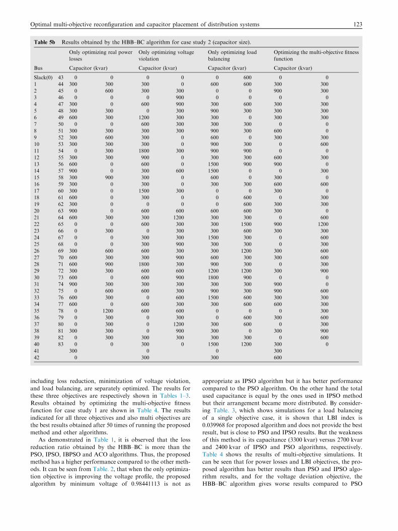
Table 5b Results obtained by the HBB–BC algorithm for case study 2 (capacitor size).
Only optimizing real power
losses
Only optimizing voltage
violation
Only optimizing load
balancing
Optimizing the multi-objective fitness
function
Bus Capacitor (kvar) Capacitor (kvar) Capacitor (kvar) Capacitor (kvar)
Slack(0) 43 0 0 0 0 0 600 0 0
1 44 300 300 300 0 600 600 300 300
2 45 0 600 300 300 0 0 900 300
3 46 0 0 0 900 0 0 0 0
4 47 300 0 600 900 300 600 300 300
5 48 300 300 0 300 900 300 300 300
6 49 600 300 1200 300 300 0 300 300
7 50 0 0 600 300 300 300 0 0
8 51 300 300 300 300 900 300 600 0
9 52 300 600 300 0 600 0 300 300
10 53 300 300 300 0 900 300 0 600
11 54 0 300 1800 300 900 900 0 0
12 55 300 300 900 0 300 300 600 300
13 56 600 0 600 0 1500 900 900 0
14 57 900 0 300 600 1500 0 0 300
15 58 300 900 300 0 600 0 300 0
16 59 300 0 300 0 300 300 600 600
17 60 300 0 1500 300 0 0 300 0
18 61 600 0 300 0 0 600 0 300
19 62 300 0 0 0 0 600 300 300
20 63 900 0 600 600 600 600 300 0
21 64 600 300 300 1200 300 300 0 600
22 65 0 0 600 300 300 1500 900 1200
23 66 0 300 0 300 300 600 300 300
24 67 0 0 300 300 1500 300 0 600
25 68 0 0 300 900 300 300 0 300
26 69 300 600 600 300 300 1200 300 600
27 70 600 300 300 900 600 300 300 600
28 71 600 900 1800 300 900 300 0 300
29 72 300 300 600 600 1200 1200 300 900
30 73 600 0 600 900 1800 900 0 0
31 74 900 300 300 300 300 300 900 0
32 75 0 600 600 300 900 300 900 600
33 76 600 300 0 600 1500 600 300 300
34 77 600 0 600 300 300 600 600 300
35 78 0 1200 600 600 0 0 0 300
36 79 0 300 0 300 0 600 300 600
37 80 0 300 0 1200 300 600 0 300
38 81 300 300 0 900 300 0 300 900
39 82 0 300 300 300 300 300 0 600
40 83 0 0 300 0 1500 1200 300 0
41 300 0 0 300
42 0 300 300 600
Optimal multi-objective reconfiguration and capacitor placement of distribution systems 123
including loss reduction, minimization of voltage violation,and load balancing, are separately optimized. The results for
these three objectives are respectively shown in Tables 1–3.Results obtained by optimizing the multi-objective fitnessfunction for case study 1 are shown in Table 4. The results
indicated for all three objectives and also multi objectives arethe best results obtained after 50 times of running the proposedmethod and other algorithms.
As demonstrated in Table 1, it is observed that the lossreduction ratio obtained by the HBB–BC is more than thePSO, IPSO, IBPSO and ACO algorithms. Thus, the proposedmethod has a higher performance compared to the other meth-
ods. It can be seen from Table. 2, that when the only optimiza-tion objective is improving the voltage profile, the proposedalgorithm by minimum voltage of 0.98441113 is not as
appropriate as IPSO algorithm but it has better performancecompared to the PSO algorithm. On the other hand the total
used capacitance is equal by the ones used in IPSO methodbut their arrangement became more distributed. By consider-ing Table. 3, which shows simulations for a load balancing
of a single objective case, it is shown that LBI index is0.039968 for proposed algorithm and does not provide the bestresult, but is close to PSO and IPSO results. But the weakness
of this method is its capacitance (3300 kvar) versus 2700 kvarand 2400 kvar of IPSO and PSO algorithms, respectively.Table 4 shows the results of multi-objective simulations. Itcan be seen that for power losses and LBI objectives, the pro-
posed algorithm has better results than PSO and IPSO algo-rithm results, and for the voltage deviation objective, theHBB–BC algorithm gives worse results compared to PSO

Table 6 Results obtained by optimizing real power losses with HBB–BC algorithm along with a comparison with SA, GA and ACSA.
Item Power losses (kW) Minimum voltage (p.u) LBI
Original configuration 531.99 0.9285191 0.0329944
HBB–BC Best 296.47 0.9850667 0.0180701
Worst 303.7 0.98378407 0.01724226
Average 300.08 0.9844253 0.01765618
Average loss reduction 43.6 – –
SA [30] Best 309.12 – –
Worst 315.86 – –
Average 312.30 – –
Average loss reduction 41.3 – –
GA[30] Best 295.39 – –
Worst 299.13 – –
Average 297.75 – –
Average loss reduction 44.03 – –
ACSA [30] Best 295.12 – –
Worst 299.46 – –
Average 296.89 – –
Average loss reduction 44.19 – –
Figure 8 Voltage profiles before and after optimal reconfiguration and capacitor placement in 94-bus system.
Figure 9 Branches current profiles before and after optimal reconfiguration and capacitor placement in 94-bus system.
124 M. Sedighizadeh, R. Bakhtiary

s1918
1 2 3 4 5
6 7
8
9 10 11 12
1314
15
17
16
20
19
21 22
23 24 25
s1 s2 s4 s6
s3
s9s8
s26
s10
s18
s13 s14 s15
s7
s23 s24s27
s21
s20 s22
s25
s16
s12
s11
s17
Figure 10 25 bus unbalanced distribution system.
Table 7 Results obtained by the HBB–BC algorithm for case study 3.
Item Initial state Only optimizing
real power losses
Only optimizing
voltage violation
Only optimizing
load balancing
Optimizing the multi-objective
fitness function
Power losses (kW) 150.13 91.28 146.377 149.973 94.179
Loss reduction (%) – 39.2 2.5 0.104 37.29
Minimum voltage Phase a (p.u.) 0.9284107 0.9640415 0.9877222 0.9740478 0.964586
Minimum voltage Phase b (p.u.) 0.9283703 0.9626266 0.985857 0.9694966 0.963076
Minimum voltage Phase c (p.u.) 0.9365706 0.9695176 0.9932599 0.9804585 0.9725021
LBI 0.1009584 0.0454020 0.0735533 0.0328862 0.0455454
Open switches 25-26-27 22-17-15 20-17-15 5-11-13 25-17-15
Capacitor (kvar) (bus) – 300 (3-4-7) 300 (5-8-11-12-14) 300 (10-16-17-19) 300 (2-3-9)
Optimal multi-objective reconfiguration and capacitor placement of distribution systems 125
and IPSO algorithm. However, the results are close to those ofPSO and IPSO (the minimum voltages in HBB–BC algorithm
is within the allowed range). Yet, the proposed and the PSOmethod use the same installed capacitors (2400 kvar), and theyuse less capacitors than IPSO method (3000 kvar). Figs. 4 and
5 show the voltage and branches current profiles before andafter optimal reconfiguration and capacitor placement, respec-tively. Fig. 5 shows line capacity for network branches. As
shown in these figures, the voltage and current branches profileis obviously improved by using the HBB–BC algorithm. Fig. 6indicates the convergence characteristic of the HBB–BC for themulti-objective function for case study 1. It is shown that after
18 iterations HBB–BC algorithm reaches to full convergenceand fitness function value at approximately 0.83 remainsconstant.
Case study 2: The second example is a practical distributionnetwork of the Taiwan Power Company [49]. It is a three-phase, 11.4-kV system which consists of 94-bus, 96 branches,
11 feeders, 83 sectionalizing switches (normally close switches),
and 13 tie switches (normally open switches). Fig. 7 shows adiagram of this system which has a total load of 28,350 kW
and 20,700 kvar. Details of the data of this example can befound in [49]. In this network, an Aluminum Conductor SteelReinforced (ACSR) 477 kCmil has been employed for the
overhead lines and a copper conductor 500 kCmil for theunderground lines. The capacities of these conductors are670 and 840 A, respectively [50].
The initial power loss is 531.99 kW and minimum bus volt-age is 0.9285 p.u. To optimize the multi objective fitness func-tion, parameters were selected as follows: the number ofpopulation was set at 25, a1, a2 and a3 were set at 1, 0.4 and
0.8 respectively, and the mutation probability and maximumiterations were set at 0.002 and 200 respectively. The resultsindicated for all the three objectives and also the multi objec-
tive function are the best results obtained after 50 times run-ning the proposed method.
The optimal solutions for minimization of total real power
losses, the minimization of buses voltage violation, and load

Figure 11 Voltage profiles before and after optimal reconfiguration and capacitor placement in 25-bus system.
126 M. Sedighizadeh, R. Bakhtiary
balancing and optimal solution for the multi-objective func-
tion are illustrated in Table 5. The optimal solution for theminimization of total real power losses using the HBB–BCand SA, GA and ACSA is shown in Table 6 along with a com-
parison with SA, GA and ACSA. As can be seen from Table 6,the proposed method has better performance compared to theSA algorithm, but GA and ACSA have better performance
compared to the HBB–BC algorithm. Figs. 8 and 9 show thevoltage and branches current profiles before and after optimalreconfiguration and capacitor placement for Case study 2,respectively. Fig. 9 shows line capacity for network branches.
As shown in these Figures, the voltage and current branches
profile is obviously improved by using the HBB–BC algorithm.Case study 3: the third case study is a 25-bus Unbalanced
Distribution 4.16-kV System consisting of 24 sectionalizing
switches (normally close switches) and 3 tie switches (normallyopen switches). Details for the line and load data of the systemcan be found in [51]. This system is shown in Fig. 10. The ini-
tial power loss is 150.13 kW and minimum bus voltage inphases a, b and c is 0.9284107, 0.9283703 and 0.9365706 p.u.respectively. To optimize the multi objective fitness function,the parameters were selected as follows: the number of

Figure 12 Convergence characteristic of HBB–BC for the multi-objective function for case study 3.
Optimal multi-objective reconfiguration and capacitor placement of distribution systems 127
population was set at 20, and a1, a2 and a3 were set at 1, 0.4and 0.8 respectively, and the mutation probability and maxi-
mum iterations were set at 0.01 and 100 respectively. The opti-mal solutions for only minimizing the total real power losses,only minimizing the buses voltage violation, only load balanc-
ing and the optimal solution for the multi-objective functionare presented in Table 7. The results indicated for all the threeobjectives and also the multi-objective function are the best
results obtained after 50 instances of running the proposedmethod. Fig. 11 shows the voltage profiles in phase a, phaseb and phase c of case study 3 before and after optimalreconfiguration and capacitor placement. Fig. 12 shows the
convergence characteristic of the HBB–BC for case study 3.As shown in Fig. 12, fitness function after 35 iterations con-verges to 0.79 and the voltages profile is obviously improved
using the HBB–BC algorithm in each phase.
6. Conclusions
An HBB–BC optimization algorithm as the combination ofthe BB–BC algorithm and the capability of the PSO algorithmfor multi-objective reconfiguration and capacitor placement of
balanced and unbalanced distribution systems in a fuzzyframework has been introduced in this paper. In fact, this algo-rithm utilizes the PSO’s capabilities to improve the search abil-
ity and also uses a mutation operator to reduce the problem ofthe algorithm being trapped into the local optimum problem.An important property of the proposed approach is solvingthe multi-objective reconfiguration and capacitor placement
problem in the fuzzy framework. The objectives consideredare the minimization of total network real power losses, theminimization of buses voltage violation, and load balancing
in the feeders. To obtain the optimal solution for the multi-objective fitness function, first each objective is transferred intothe fuzzy domain using the membership function and then the
resultant overall fuzzy satisfaction function is considered as afitness function, which is maximized during the optimizationprocess. The proposed method has been successfully tested in
three case studies (consisting of two balanced and one unbal-anced system). In case study 1, the HBB–BC has shown betterperformance compared to PSO and IPSO algorithms forpower losses and LBI objectives. However, it gives less mini-
mum voltage compared to PSO and IPSO algorithms. In case
study 2, the HBB–BC has shown a better performance com-pared to the SA, and has shown a performance almost similar
to that of the GA and ACSA. As can be seen from simulationresults, the proposed algorithm is an effective method for find-ing the optimal solution. It is also a powerful method for solv-
ing optimization problems in the fuzzy framework forbalanced and unbalanced distribution networks.
References
[1] Imran AM, Kowsalya M. A new power system reconfiguration
scheme for power loss minimization and voltage profile enhance-
ment using Fireworks Algorithm. Int J Electr Power Energy Syst
2014;62:312–22.
[2] Oliveira EJD, Rosseti GJ, Oliveira LWD, Gomes FV, Peres W.
New algorithm for reconfiguration and operating procedures in
electric distribution systems. Int J Electr Power Energy Syst
2014;57:129–34.
[3] Shareef H, Ibrahim AA, Salman N, Mohamed A, Ling Ai W.
Power quality and reliability enhancement in distribution systems
via optimum network reconfiguration by using quantum firefly
algorithm. Int J Electr Power Energy Syst 2014;58:160–9.
[4] Abdelaziz A, Mohamed F, Mekhamer S, Badr M. Distribution
system reconfiguration using a modified Tabu search algorithm.
Electr Power Syst Res 2010;80(8):943–53.
[5] Oliveira LWD, Oliveira EJD, Gomes FV, Silva Jr IC, Marcato
ALM, Resende PVC. Artificial Immune Systems applied to the
reconfiguration of electrical power distribution networks for
energy loss minimization. Int J Electr Power Energy Syst
2014;56:64–74.
[6] Sedighizadeh M, Ahmadi S, Sarvi M. An efficient Hybrid Big
Bang–Big Crunch algorithm for multi-objective reconfiguration of
balanced and unbalanced distribution systems in fuzzy frame-
work. Electr Power Compo Syst 2013;41(1):75–99.
[7] Savier JS, Das D. Impact of network reconfiguration on loss
allocation of radial distribution systems. IEEE Trans Power Deliv
2007;22(4):2473–80.
[8] Swarnkar A, Gupta N, Niazi KR. Adapted ant colony optimiza-
tion for efficient reconfiguration of balanced and unbalanced
distribution systems for loss minimization. Swarm Evol Comput
2011;1(3):129–37.
[9] Tristiu I, Eremia M, Bulac C, Toma L. Multi-criteria reconfig-
uration of distribution electrical networks for minimization of
power losses and damage cost due to power supply interruption.
In: Proc 2007 IEEE Lausanne power tech, Lausanne; 2007.
p. 385–90.

128 M. Sedighizadeh, R. Bakhtiary
[10] Amanulla B, Chakrabarti S, Singh SN. Reconfiguration of power
distribution systems considering reliability and power loss. IEEE
Trans Power Deliv 2012;27(2):918–26.
[11] Mendoza JE, Lopez ME, Coello CA, Lopez EA. Microgenetic
multiobjective reconfiguration algorithm considering power losses
and reliability indices for medium voltage distribution network.
IET Gener Transm Distrib 2009;3(9):825–40.
[12] Bernardon DP, Garcia VJ, Ferreira ASQ, Canha LN. Multicri-
teria distribution network reconfiguration considering subtrans-
mission analysis. IEEE Trans Power Deliv 2010;25(4):2684–91.
[13] Zidan A, El-Saadany EF. Multi-objective network reconfigura-
tion in balanced distribution systems with variable demand. In:
Proc 2nd international conference on electric power and energy
conversion systems (EPECS), Sharjah; 2011. p. 1–6.
[14] Tomoiaga B, Chindris� M, Sumper A, Sudria-Andreu A, Vil-
lafafila-Robles R. Pareto optimal reconfiguration of power
distribution systems using a genetic algorithm based on NSGA-
II. Energies 2013;6(3):1439–55.
[15] Mazza A, Chicco G, Russo A. Optimal multi-objective distribu-
tion system reconfiguration with multi criteria decision making-
based solution ranking and enhanced genetic operators. Int J
Electr Power Energy Syst 2014;54:255–67.
[16] Ramadan HA, Wahab MAA, El-Sayed AHM, Hamada MM. A
fuzzy-based approach for optimal allocation and sizing of
capacitor banks. Electr Power Syst Res 2014;106:232–40.
[17] Franco JF, Rider MJ, Lavorato M, Romero R. A mixed-integer
LP model for the optimal allocation of voltage regulators and
capacitors in radial distribution systems. Int J Electr Power
Energy Syst 2013;48:123–30.
[18] Abul’Wafa AR. Optimal capacitor allocation in radial distribu-
tion systems for loss reduction: a two stage method. Electr Power
Syst Res 2013;95:168–74.
[19] Carpinelli G, Noce C, Proto D, Russo A, Varilone P. Single-
objective probabilistic optimal allocation of capacitors in unbal-
anced distribution systems. Electr Power Syst Res 2012;87:47–57.
[20] Sedighizadeh M, Kalimdast F. A Honey Bee Foraging Approach
to optimal capacitor placement with harmonic distortion consid-
eration. Int Rev Electr Eng 2012;7(1):3592–601.
[21] Sedighizadeh M, Arzaghi-haris D. Optimal allocation and sizing
of capacitors to minimize the distribution line loss and to improve
the voltage profile using Big Bang–Big Crunch optimization. Int
Rev Electr Eng 2011;6(4):2013–9.
[22] Augugliaro A, Cataliotti V, Dusonchet L. Optimal compensation
and reconfiguration for the minimum losses operation of MV
automated networks: An evolutionary solving approach. In: Proc
CIRED, Buenos Aires, Argentina; 1996. p. 71–76.
[23] Augugliaro A, Dusonchet L, Sanseverino ER. A mixed greedy-
tabu search strategy for optimal operation of MV radial distri-
bution networks. In: Proc UPEC 97, Manchester, UK; 1997. p.
10–12.
[24] Augugliaro A, Dusonchet L, Sanseverino ER. A new multiobjec-
tive optimization method to solve the compensation and recon-
figuration problem in automated distribution networks. In: Proc
UPEC 99, Leicester, UK; 1999. p. 14–16.
[25] Jiang D, Baldick R. Optimal electric distribution system switch
reconfiguration and capacitor control. IEEE Trans Power Syst
1996;11:890–9.
[26] Augugliaro A, Dusonchet L, Sanseverino ER. Genetic, simulated
annealing and tabu search algorithms: three heuristic methods for
optimal distribution network’s reconfiguration and compensation.
ETEP Eur Trans Electr Power Eng 1999;9(1):35–41.
[27] Augugliaro A, Dusonchet L, Sanseverino ER. Voltage regulation
and power losses minimization in automated distribution net-
works by an evolutionary multiobjective approach. IEEE Trans
Power Syst 2004;19(3):1516–27.
[28] Zhang D, Fu Z, Zhang L. Joint optimization for power loss
reduction in distribution systems. IEEE Trans Power Syst 2008;23
(1):161–9.
[29] Farahani V, Vahidi B, Askarian Abyaneh H. Reconfiguration and
capacitor placement simultaneously for energy loss reduction
based on an improved reconfiguration method. IEEE Trans
Power Syst 2012;27(2):587–95.
[30] Chung-Fu Chang. Reconfiguration and capacitor placement for
loss reduction of distribution systems by Ant Colony Search
Algorithm. IEEE Trans Power Syst 2008;23(4):1747–55.
[31] Montoya DP, Ramirez JM. Reconfiguration and optimal capac-
itor placement for losses reduction. In: Sixth IEEE/PES trans-
mission and distribution: Latin America conference and
exposition, Montevideo; 2012. p. 1–6.
[32] Guimaraes MAN, Castro CA, Romero R. Distribution systems
operation optimization through reconfiguration and capacitor
allocation by a dedicated genetic algorithm. IET Gener Transm
Distrib 2010;4(11):1213–22.
[33] Sedighizadeh M, Dakhem M, Sarvi M, Kordkheili HH. Optimal
reconfiguration and capacitor placement for power loss reduction
of distribution system using improved binary particle swarm
optimization. Int J Energy Environ Eng 2014:1–11.
[34] Tang H, Zhou J, Xue S, Xie L. Big bang-big crunch optimization
for parameter estimation in structural systems. Mech Syst Signal
Process 2010;24(8):2888–97.
[35] Saffar A, Hooshmand R, Khodabakhshian A. A new fuzzy
optimal reconfiguration of distribution systems for loss reduction
and load balancing using ant colony search-based algorithm. Appl
Soft Comput 2011;11(5):4021–8.
[36] Akorede MF, Hizam H, Aris I, Ab Kadir MZA. Effective method
for optimal allocation of distributed generation units in meshed
electric power systems. IET Gener Transm Distrib 2011;5
(2):276–87.
[37] Esmaili M. Placement of minimum distributed generation units
observing power losses and voltage stability with network
constraints. IET Gener Transm Distrib 2013;7(8):813–21.
[38] Gupta N, Swarnkar A, Niazi KR, Bansal RC. Multi-objective
reconfiguration of distribution systems using adaptive genetic
algorithm in fuzzy framework. IET Gener Transm Distrib 2010;4
(12):1288–98.
[39] Sedighizadeh M, Ghalambor M, Rezazadeh A. Reconfiguration
of radial distribution systems with fuzzy multi-objective approach
using modified Big Bang–Big Crunch algorithm. Arab J Sci Eng
2014;39:6287–96.
[40] Erol OK, Eksin I. A new optimization method: Big bang–big
crunch. Adv Eng Softw 2006;37(2):106–11.
[41] Kaveh A, Talatahari S. Size optimization of space trusses using
big bang–big crunch algorithm. Comput Struct 2009;87(17–
18):1129–40.
[42] Kennedy J, Eberhart RC. Particle swarm optimization. In: Proc
IEEE Int’l conf neural networks, Piscataway, NJ; 1995. p. 1942–
48.
[43] Ibrahim HEA, Hassan FN, Shomer AO. Optimal PID control of
a brushless DC motor using PSO and BF techniques. Ain Shams
Eng J 2014;5:391–8.
[44] Das S, Abraham S, Konar A. Spatial information based image
segmentation using a modified particle swarm optimization
algorithm. In: Sixth International conference on intelligent
systems design and applications (ISDA), vol. 2, Jinan; 2006. p.
438–44.
[45] Duque FG, Oliveira LW, Oliveira EJ, Marcato ALM, Silva
Junior IC. Allocation of capacitor banks in distribution systems
through a modified monkey search optimization technique. Int J
Electr Power Energy Syst 2015;73:420–32.
[46] Teng JH. A direct approach for distribution system load flow
solutions. IEEE Trans Power Deliv 2003;18(3):882–7.
[47] Baran ME, Wu FF. Network reconfiguration in distribution
systems for loss reduction and load balancing. IEEE Trans Power
Deliv 1989;4(2):1401–7.
[48] Kasaei M, Gandomkar M. Loss reduction in distribution system
with simultaneous using of capacitor placement and reconfigura-

Optimal multi-objective reconfiguration and capacitor placement of distribution systems 129
tion by a colony algorithm. In: 24th International power system
conference, Tehran, Iran; 2009.
[49] Su CT, Lee CS. Network reconfiguration of distribution systems
using improved mixed-integer hybrid differential evolution. IEEE
Trans Power Deliv 2003;18(3):1022–7.
[50] Rivas Davalos F, Irving MR. The edge-set encoding in evolu-
tionary algorithm for network reconfiguration problems in power
distribution systems. In: 16th PSCC, Glasgow, Scotland; 2008.
p. 1–7.
[51] Vulasala G, Sirigiri S, Thiruveedula R. Feeder reconfiguration for
loss reduction in unbalanced distribution system using genetic
algorithm. Int J Elect Electron Eng 2009;3(12):754–62.
Mostafa Sedighizadeh received the B.S. degree
in Electrical Engineering from the Shahid
Chamran University of Ahvaz, Iran, and M.S.
and Ph.D. degrees in Electrical Engineering
from the Iran University of Science and
Technology, Tehran, Iran, in 1996, 1998 and
2004, respectively. From 2000 to 2007, he was
with power system studies group of Moshanir
Company, Tehran, Iran. Currently, he is as an
Assistant professor with the Faculty of Elec-
trical and Computer Engineering, Shahid
Beheshti University, Tehran, Iran. His research interests are Power
system control and modeling, FACTS devices and Distributed Gen-
eration.
Reza Bakhtiary received his B.C degree in
electrical engineering from university of Buali,
Hamedan, Iran, in 2012 and M.S degree in
electrical engineering from Shahid Beheshti
University, Tehran, Iran, in 2014. His research
interests are power system reliability, smart
grid and renewable energies.