optimal design of pd-fuzzy-pid cascaded controller for ... · pdf fileautomatic generation...
TRANSCRIPT

Debnath et al., Cogent Engineering (2017), 4: 1416535https://doi.org/10.1080/23311916.2017.1416535
SYSTEMS & CONTROL | RESEARCH ARTICLE
Optimal design of PD-Fuzzy-PID cascaded controller for automatic generation controlManoj Kumar Debnath1*, Tarakanta Jena1 and Ranjan Kumar Mallick1
Abstract: In this research paper a novel cascaded PD-Fuzzy-PID controller is rec-ommended for a conventional hybrid-source unified power system for automatic generation control. The optimization of scaling parameters of the suggested PD-Fuzzy-PID controller is done by hybrid Grey Wolf Optimization-Teaching Learning Based Optimization (GWO-TLBO) technique. A sudden disturbance of 0.01 p.u. is considered in area 1 and ITAE is taken as the evaluative function in the recom-mended optimization process. The proposed work considers three different sources of generating systems namely, a hydro, a gas and a reheat thermal unit. Both AC tie-line and AC-DC tie-line is considered in analyzing the dynamic performances of the system. The robustness and sensitiveness of the proposed controller are further put to test for random load variations and nominal parameter variations. Analysis of the dynamic characteristics of the system is executed considering a number of time response specifications like settling time, peak overshoots and undershoots. During the analysis the optimum specifications obtained by the recommended technique are compared with some pre-published results in order to prove the supremacy of this novel controller over existing controllers. Further, the frequency stability of the system is improved by employing an UPFC in the system.
Subjects: Artificial Intelligence; Energy & Fuels; Power Engineering; Systems & Controls
Keywords: fuzzy control; automatic generation control; grey wolf optimization; teaching learning based optimization; cascaded PD-fuzzy-PID controller; multi-source system
*Corresponding author: Manoj Kumar Debnath, Department of Electrical Engineering, Siksha ‘O’ Anusandhan University, Bhubaneswar, 751030, Odisha, India E-mail: [email protected]
Reviewing editor:James Lam, University of Hong Kong, Hong Kong
Additional information is available at the end of the article
ABOUT THE AUTHORManoj Kumar Debnath received his B.Tech. degree from Biju Pattnaik University of Technology, Odisha, India in 2007 and M.Tech. degree in power system in 2013 from Siksha ‘O’ Anusandhan university, Odisha, India. Since 2008, he has been working as a lecturer at Siksha ‘O’ Anusandhan University, Odisha, India. His research interest includes the application of artificial intelligence and soft computing in power system control.
PUBLIC INTEREST STATEMENTDue to the progressive increase in the size of the power system, the necessity of keeping the frequency and tie-line power within recommended limits has become a major concern. So this is a challenge for the engineers to keep the power system consistent and secure. This article proposed a novel PD-Fuzzy-PID cascaded controller for automatic generation control of an interconnected power system which helps in maintaining the frequency and tie-line power deviations in the system within specified limits. By the introduction of such controller the frequency deviation in the interconnected power system can be regulated in a better way which in turn balances the net generation in accordance to the demand.
Received: 14 August 2017Accepted: 08 December 2017First Published: 13 December 2017
© 2017 The Author(s). This open access article is distributed under a Creative Commons Attribution (CC-BY) 4.0 license.
Page 1 of 27
Manoj Kumar Debnath

Page 2 of 27
Debnath et al., Cogent Engineering (2017), 4: 1416535https://doi.org/10.1080/23311916.2017.1416535
1. IntroductionDue to the progressive increase in the size of the power system, the obligation of keeping the fre-quency and exchange of tie-line power inside recommended restrictions has become inevitable. So this becomes a challenge for the engineers to keep the power system consistent and secure. Power system all over the world has now become interconnected, i.e. small individual units of power sys-tem gets joined with each other using tie-lines forming a unified area. There is a compulsion of maintaining the deviations in system constraints within specified limits, with the purpose of preserv-ing the stability of the power system. AGC in each area plays a major role by examining the fre-quency and the tie line power. It balances the net generation in accordance to the demand. The nullification of system error can be done by regulating Area Control Error which is the actuating signal for AGC. AGC operates to meet the demand in a specified area with random changes in the load in a controlled manner. It wishes to regulate the frequency and inter-area power flow close to prescribed values (Kundur, 1994).
A thorough and extensive research has been done over the past years on various control strate-gies of AGC in order to maintain system deviations within prescribed limits during normal and abnor-mal operating conditions. Classical methods of frequency and inter-area power control were first proposed in 1957 (Cohn, 1956). In this paper the various load curves were explained and the prob-lem was solved with the help of a numerical example. The concept of multi area modelling for the AGC technique of the interconnected area is proposed in (Kothari & Nanda, 1988). Y. Wang described the single area power system scenario and applied AGC using generation rate constants (GRC) in paper (Wang, Zhou, & Wen, 1994). K. R. Mudi and R. N Pal, in the paper (Mudi & Pal, 1999), described a self-tuning scheme optimized fuzzy logic controller which is simple but robust in nature. For a smoother control of frequency, apart from the speed control of the governor, the concept of a sec-ondary control using PI controllers was proposed in (Nanda, Mangla, & Suri, 2006). In (Nanda, Mishra, & Saikia, 2009) J Nanda et al. explained the bacteria foraging based AGC in multi-area intercon-nected power system. A comprehensive comparison of various classical controllers and their perfor-mance evaluation for thermal system having a multi-area was aptly presented in (Nanda & Saikia, 2008). The concept of a robust PID controller for LFC was first proposed in (Shabani, Vahidi, & Ebrahimpour, 2013). With a greater efficiency fractional order controller was efficiently used in (Alomoush, 2010) for load frequency control. The effectiveness of the controller is governed by the time taken by the ACE to come to zero. This depends upon the proper extent of optimization of the controller gains. Earlier methods of setting these gains were traditional hit and trial methods. These classical methods were time consuming and less efficient. With the successful research on Meta-heuristic optimization techniques and bio-inspired computational schemes, the controller gains can now be properly optimized. Various bio-inspired computational schemes came into existence like Particle swarm optimization (PSO), bacterial foraging algorithm (BFOA), differential evolution tech-nique (DE) and a lot more. The researchers focussed on the application of these techniques to opti-mize the controller gains. The concept of Load Frequency Control optimized by Genetic Algorithm (GA) in fuzzy rule was proposed in (Ghoshal & Goswami, 2003). The first application of Particle Swarm Optimization (PSO) technique along with fuzzy rule base for the AGC is clearly described in (Ghoshal, 2004). The implementation of HVDC lines and the study of AGC using optimal regulators was aplty described in (Singh & Nasiruddin, 2016). Use of an adaptive fuzzy logic approach for the load fre-quency control of the multi source power system was effectively elaborated in (Yousef, Khalfan, Albadi, & Hosseinzadeh, 2014). In paper (Mohanty, Panda, & Hota, 2014a) the Differential Evolution technique was used for frequency regulation for unified systems with non-linearities. Paper (Khuntia & Panda, 2012) puts to picture the simulation study of AGC using ANFIS (Artificial Neuron-Fuzzy Inference System). Application of various FACTS devices and SMES (Superconducting Magnetic Energy Storage) in conventional power system for AGC was portrayed by Barisal et al. in (Lal & Barisal, 2017). Hybrid evolutionary algorithm based fuzzy logic controller for automatic generation control of power systems with governor dead band non-linearity was effectively proposed in (Singh & Nasiruddin, 2016) by O. Singh et al. The implementation of optimal Gravitational search algorithms for tuning the controller parameters for the AGC of an interconnected power system is put effec-tively in (Sahu, Panda, & Padhan, 2014). Differential evolution as the computation technique to tune

Page 3 of 27
Debnath et al., Cogent Engineering (2017), 4: 1416535https://doi.org/10.1080/23311916.2017.1416535
the controller gains in the AGC of an interconnected power system was analysed effectively in (Rout, Sahu, & Panda, 2013). R K Sahu, S. Panda in their research paper (Rout et al., 2013) has clearly de-scribed a hybrid optimization technique with firefly algorithm and pattern search algorithm for AGC in unified power systems. Paper (Ismayil, Kumar, & Sindhu, 2015) defined Genetic Algorithm based fractional order PID controller for AGC of a two area power system. In article (Manoj Kumar Debnath, Mallick, & Aman, 2016), Gravitational Search Algorithm is used for tuning Fuzzy-PID controller for load frequency control in an unified two area power system. The concept of Teaching and Learning Based Optimization (TLBO) was first introduced in the paper (Rao, Savsani, & Vakharia, 2012). A new optimization technique known as Grey Wolf Optimizer was introduced in (Mirjalili, Mirjalili, & Lewis, 2014). In (Sahu, Gorripotu, & Panda, 2016) R. K. Sahu et al. applied the TLBO optimization technique for AGC using Proportional-Integral-Double Derivative (PIDD) controller. Most recent optimization technique, i.e. the Grey Wolf Optimization technique is successfully implemented for Load frequency control of a multi area Power system by Dipayan Guha, Provas Kumar Roy and Subrata Banerjee (Guha, Roy, & Banerjee, 2016). In paper (Sahu, Pati, & Panda, 2014) the authors have clearly illus-trated the hybrid DE-PSO technique for frequency regulation in a hybrid source power system. In (Mohanty, Panda, & Hota, 2014b) the AGC was carried on a hybrid source power system using the differential evolution algorithm. A hybrid LUS-TLBO (Local Unmoral Sampling-Teaching Learning based optimization) tuned Fuzzy-PID controller has been proposed successfully in (Sahu, Pati, Nayak, Panda, & Kar, 2016) for AGC of hybrid-source power system. P.C. Pradhan and et al. have proposed frequency control in hybrid-source systems with UPFC and SMES considering firefly algorithm (Pradhan, Sahu, & Panda, 2016). Paper (Arya, 2017) effectively portrays the use of a new fractional order fuzzy PID controller to enhance the performance of the system. The gains of the controller as well as the Fuzzy scaling factors were optimized by ICA (imperialist competitive algorithm) and the effectiveness is successfully established. Thereafter, many techniques have been proposed in the multi-source system including redox flow batteries (Arya & Kumar, 2016a) for automatic generation control. In paper (Arya & Kumar, 2016b) AGC of a multi-source sytem is performed under deregu-lated environment. Y. Arya (Arya & Kumar, 2016c) proposed a novel controller called Fuzzy gain scheduling controller for AGC of a two area nonreheat thermal system. Paper (Padhy, Panda, & Mahapatra, 2017) portrays a modified GWO technique based cascade PI-PD controller for AGC of power systems in presence of Plug in Electric Vehicles. In paper (El-Hameed & El-Fergany, 2016), Load frequence control of a multi-area system using water cycle algorithm based PID controller was effectively analysed. Paper (Ou & Hong, 2014) analyses the operation and control of a microgrid comprising of wind power system, photovoltaic source and fuel cell. Paper (Ou, Lu, & Huang, 2017) applied a novel intelligent damping controller (NIDC) for the static synchronous compensator (STATCOM) to reduce the power fluctuations, voltage support and damping in a hybrid power multi-system. In paper (Ou, 2012) a novel unsymmetrical faults analysis for microgrid distribution systems was discussed. Paper (Ou, 2013) deals with the Ground fault current analysis with a direct building algorithm for microgrid distribution.
From the Literature survey, it becomes clear that a large number of research works were devel-oped using a single control loop, but in our present work emphasis is given to the development of two control loops. In this regards the objective of the present research work can be summarized as follows.
(a) Designing novel cascaded PD-Fuzzy-PID controller and implementing in a conventional hybrid-source power system for frequency regulation.
(b) Applying hybrid GWO-TLBO algorithm to get the optimum values of the recommended control-ler parameters of the hybrid-source power system with AC link and AC-DC link.
(c) Evaluating the dynamic performance of the system and comparing this with pre-published re-sults so as to establish the supremacy of the recommended controller.

Page 4 of 27
Debnath et al., Cogent Engineering (2017), 4: 1416535https://doi.org/10.1080/23311916.2017.1416535
(d) Proving the robustness and sensitiveness of the system by varying the load of the system ran-domly, also by varying the parameters of the system.
(e) Improving the frequency stability of the system by employing an UPFC in the system.
2. System examinedIn this research analysis three types of generating sources are implemented in each area of a two area unified power system. The generating sources include a gas unit, a thermal unit with reheat turbine and a hydro unit. The parameters of the system are taken from previously published re-search work (Sahu et al., 2016) listed in the Appendix A. Figure 1 displays the linearized model of the proposed work. The dynamic performance of the system is investigated considering an SLP of 1% (0.01pu) applied to area 1 only. Initially the system peformances are investigated in two cases, with-out and with HVDC link. Then the system behaviour is examined with the inclusion of UPFC. Each area has a distinct PD-fuzzy-PID cascaded controller for maintaining the variations in frequency and tie-line power. While regulating the system deviations, the ACE is also minimized. The ACE for each ar-eas is expressed as
where ΔPtie is the interline power variation between both the areas, B1 and B2 are frequency bias coef-ficients of respective area. Δf1 and Δf2 are frequency variations in respective area.
(1)ACE1= ΔPtie1−2 + B1Δf1
(2)ACE2= ΔPtie2−1 + B2Δf2
Figure 1. The hybrid-source power system model (Sahu et al., 2016) represented by transfer functions.

Page 5 of 27
Debnath et al., Cogent Engineering (2017), 4: 1416535https://doi.org/10.1080/23311916.2017.1416535
3. The proposed optimization algorithm
3.1. Grey wolf optimization techniqueBrought to picture in 2014 by Mirjalili et al. (2014), this algorithm draws its inspiration from the social behaviour and the leadership hierarchy of the grey wolves. Grey wolves (Canis Lupus) are the mem-ber of the Canidae family and belong to the topmost level of the food cycle. They are also referred as the apex predator. The wolves mainly prefer to survive in a group (pack) and the number of members in a pack is on an average 5–12. Each and every such pack of wolves exhibits a social dominant hier-archy among them. Of each group a male and a female is taken as a leader named as alphas. The alphas are mainly responsible to take important decisions in a group. Whatever decisions the alphas take, they are strictly followed by the entire group. However there are some democratic traits in each group which is also maintained because in many situations it has been seen that the alphas follow the rest of the pack. The alphas are the most dominant in the group though they are not the strong-est in the pack. The dominance of alpha is governed by its managerial capacities.
The next hierarchy in the pack is the betas. The beta wolves are subordinate to the alphas and they aid the alphas in the entire decision-making and the managerial decisions. The beta wolves are also most apt to take over the position of the alphas when they pass away. The beta wolves obey the alpha but rule over the bottom layer of the pack. It acts as an advisor for the alpha and plays a dis-ciplinary role for the rest of the pack. All the major decisions of the alpha are conveyed to the rest of the pack with the help of beta.
The last tier of this hierarchical structure is the omegas. The omegas are the least dominant mem-bers in the group and acts as a scapegoat to the dominant wolves. All the frustrations and the anger of the upper tier of wolves are vented out through these weak wolves and they are permitted to eat last.
Apart from the above three tiers there are wolves who are not alpha neither beta neither omega. They are sometimes referred to as the deltas. They are dominated by the alphas and the betas but they rule over the omegas. They mainly belong to the caretaker and the sentinel post of the pack. The methodology of predation is categorized as follows:
(i) Tracking, racing and approaching the prey.
(ii) Encompassing and stepping towards the prey.
(iii) Attacking the prey.The encompassing nature of the wolves can be mathematically expressed as:
In the above expressions the parameters A⃗ and C⃗ are expressed as
“t” stands for the current iteration and the coefficient vectors are represented by A⃗ and C⃗. X⃗ is the current wolf position. The Grey wolves are known for their unique ability to assess the location of the
(3)D⃗ =|||C⃗Xp(t) − X⃗
|||
(4)X⃗(t + 1) = X⃗P(t) − A⃗.D⃗
(5)A⃗ = 2a⃗r⃗1− a⃗
(6)C⃗ = 2r⃗2

Page 6 of 27
Debnath et al., Cogent Engineering (2017), 4: 1416535https://doi.org/10.1080/23311916.2017.1416535
prey and devour them. The alphas predominantly guide the act of hunting. The positions of other wolves towards the prey are updated according to the position of alpha, beta and delta. The hunting property of alphas, betas, deltas and their position updation can be mathematically expressed as:
The steps of the GWO algorithm are proposed below:
(i) Initialization: A population of wolves is initialized randomly as xi (i = 1, 2, 3 … n) based on the upper and lower bounds of the variables. The parameters a, A and C are also initialized.
(ii) Objective function: The objective function f(x) is properly chosen to calculate the corresponding objective value or the fitness value for each wolf.
(iii) The choice of the best search agent: A proper choice for the first three wolves are done and is saved as Xα, Xβ and Xδ.
(iv) Iteration: The stopping criterion is taken as while (t < Maximum Generation)
(v) Update the position of each search agent in accordance with equation (13).
(vi) Update Xα, Xβ and Xδ.
(vii) Update the parameters a, A, and C
(viii) The value of Xα is returned as the best value.
(ix) The above process continues till the stopping criterion is encountered.
3.2. Teaching and learning based optimizationThis well-known optimization technique was developed in recent years based on the teaching-learn-ing process inside a classroom (Rao et al., 2012). To get the optimum results this optimization algo-rithm also employed population based computation like other optimization algorithms. The explanation of the algorithm is mainly achieved by two tiers: teaching phase and learning phase.
(7)D⃗𝛼=|||C⃗1X⃗𝛼(t) − X⃗
|||
(8)D⃗𝛽=|||C⃗2X⃗𝛽(t) − X⃗
|||
(9)D⃗𝛿=|||C⃗3X⃗𝛿(t) − X⃗
|||
(10)X⃗1= X⃗
𝛼− A⃗
1D⃗𝛼
(11)X⃗2= X⃗
𝛽− A⃗
2D⃗𝛽
(12)X⃗3= X⃗
𝛿− A⃗
3D⃗𝛿
(13)X⃗(t + 1) =
(X⃗1(t) + X⃗
2(t) + X⃗
3(t)
)
3

Page 7 of 27
Debnath et al., Cogent Engineering (2017), 4: 1416535https://doi.org/10.1080/23311916.2017.1416535
Socially the most educated cluster of people is identified as teachers. By getting knowledge from the teachers, the learners try to improve their talents. In this optimization process teacher acts as a best solution for the next population.
The operation of the TLBO algorithm takes part in the following stages:
Stage 1: Initialisation:
Initialisation of Parameters like random population, population size, number of students (solu-tions), and number of iterations required for termination of the process and the other design varia-bles along with their respective ranges are done in this stage.
Stage 2: A proper decision of the objective function is made. Each and every member acquires a fixed value of fitness, denoting the grade or marks obtained by the students.
Stage 3: This stage is called the Teacher Phase: In this phase the updation of the existing solution based on the best value of the fitness function is done. The solution updation is done by the following formula:
where the value of Difference\meanis obtained as
and teaching factor TF is calculated as
Now if f(Xnew,i)⟨f(Xi) then Xi = Xnew,i
Stage 4: This phase is called the learners phase. In this phase the following procedure is imple-mented to update the solution. The value of the fitness function so obtained helps in the updation of the existing solution. The details of the learner phase is given below.
Randomly select two learners Xi and Xj such that j ≠ i.
If f(Xi)⟨f(Xj) Then
Else
Now if f (Xinew�
)⟨f (Xi)then Xi = Xinew�
Stage 5: Check the stopping condition. If satisfied, return the best result otherwise go to nest iteration.
(14)Xnew , i = Xi + Difference_mean
(15)Difference_mean = rand(0, 1)[Xbest − TFMd
]
(16)TF = round[1 + rand
(0, 1
){2 − 1
}]
(17)Xinew�
= Xi + rand(0, 1)(Xi − Xj)
(18)Xinew�
= Xi + rand(0, 1)(Xj − Xi)

Page 8 of 27
Debnath et al., Cogent Engineering (2017), 4: 1416535https://doi.org/10.1080/23311916.2017.1416535
3.3. Hybrid GWO-TLBO algorithmFrom the explanation of GWO algorithm it is clear that the updation of the search agent in GWO is governed by the location of alpha, beta and delta wolves. Thus encircling, hunting and attacking are the basic and simple operators in GWO algorithm which are used to get optimum solution. But with these operators the GWO algorithm seems to be trapped in local optima. Thus GWO algorithm has a major disadvantage that it has less exploration which can be emphasized by the inclusion of more operators. On the other hand TLBO is a population based optimization which is capable of producing global optimum solution through teacher and learner phases. Thus TLBO provides more exploration and exploitation capabilities. In order to extract the best of two algorithms (GWO and TLBO) the hybrid GWO-TLBO algorithm is proposed here. The basic steps followed to develop this hybrid algo-rithm are laid below.
(i) Initialize a random population X1 based upon the limit of search space.
(ii) Apply GWO operators and get the updated population X2.
(iii) Take the final population of GWO i.e. X2 as the initial population for TLBO.
(iv) Apply TLBO operators and get the updated population X3. Accept the population X3 it is better than previous population X2.
(v) Check for the stopping condition. If satisfied, return the best result of the last step, otherwise go to the next iteration (step.ii).
4. Control methodologyIn this proposed work a cascaded PD- Fuzzy-PID controller is used. Three such controllers are imple-mented for three different sources in each area. Figure 2 vividly describes the configuration of the proposed controller. The figure clearly states that each PD-Fuzzy-PID controller consists of six scal-ing factors indicated by LP, LD, L1, L2, L3 and L4. The thermal unit, the hydro unit and the gas units have six different values of scaling factors. The main complication thereby lies in the optimization of total eighteen parameters and assigning them suitable values. The hybrid optimization technique called GWO-TLBO has been implemented for the optimization of the scaling parameters and finally mini-mizes the frequency and tie-lien power deviations. The prime objective of introducing a cascaded controller is the mitigation of the disturbance within a very short span of time and prevents it from traversing to the other part of the system. Each cascaded controller consists of two loops:
Outer loop: Also named as the master loop, it contains the proportional-derivative controller hav-ing parameters LP and LD. The input to this controller is the area control error denoted by r(t).
Inner loop: Also named as the secondary or the slave loop, it contains the Fuzzy-PID controller consisting of parameters L1, L2, L3 and L4. The outer PD controller feeds its output to the inner Fuzzy-PID controller. Also for this inner Fuzzy-PID controller the change in output frequency
(Δfi
) is given
as the feedback signal. The prime objective of the inner loop is to restrain the effect of the gain vari-ations on the system performance. The gain variations may usually arise due to the shifting in oper-ating points which can be accounted by set point changes or sustained disturbances.
The Cascaded controller has a greater advantage than the normal controller in terms of an in-creased speed of response and minimization of the system disturbances by correcting it within the system. In this proposed work the control scheme is designed with an inner Fuzzy-PID loop and an outer PD control loop. The main important section of a Fuzzy-PID controller is fuzzy logic section. The distribution of the fuzzy rules along with the membership function stands as the main hindrance of a fuzzy logic controller. The precision of fuzzy logic controller is mainly governed by the selection of the fuzzy rules provided by the expert. This paper has taken the assistance of the popular mamdani fuzzy inference system for producing the control output. The output of the inference system is fuzzy,

Page 9 of 27
Debnath et al., Cogent Engineering (2017), 4: 1416535https://doi.org/10.1080/23311916.2017.1416535
which is converted to real valued data with various defuzzification processes. Here we have used center of gravity (COG) method to get defuzzified output. For simplicity and effective computation five triangular membership functions named as fnc1, fnc2, fnc3, fnc4 and fnc5 are being used in the inference system for input and output fuzzy variables which is shown in the Figure 3. Corresponding to five membership functions twenty-five “If Then” rules are developed. Table 1 lists down the pro-posed fuzzy IF THEN rules.
5. Result and analysisIn this proposed work a hybrid GWO-TLBO algorithm has been effectively implemented to design the optimal PD-fuzzy-PID controller. The multi-source system is modelled in Matlab/Simulink environ-ment using Matlab version 7.10.0(R2010a). The hybrid GWO-TLBO algorithm is written in Matlab script file for optimization of the system parameters. The size of the population and maximum itera-tion, each taken as 100 for the optimization process. The Integral Time Absolute Error is taken as a time dependent objective function in this case. This ITAE objective function is expressed as follows.
By considering this objective function the proposed algorithm is simulated using Matlab. The gains of the PD- Fuzzy-PID controller have been optimized for two different cases, both in the presence and absence of AC-DC link. The dominance of the system is established by comparing the dynamic re-sponse of the system with pre published results like DE optimized PID controller (Mohanty et al., 2014b) and LUS-TLBO optimized Fuzzy-PID controller (Sahu et al., 2016). The convergence character-istics for TLBO, GWO and Hybrid GWO-TLBO methods are plotted in Figure 4 to ensure that proposed hybrid optimization technique provides better convergence as compared to others. In order to show the necessity of the controller in the interconnected system the system is initially simulated without any controller and the deviations of frequency in each area is observed as shown in the Figure 5. From this figure it is clear that the frequency variation of the system never attains the steady state
(19)ITAE =
t
∫0
(||Δf1|| + ||Δf2|| + ||ΔPtie||).t.dt
Figure 2. Structure of cascaded PD-Fuzzy-PID controller.
Figure 3. Triangular membership functions for the fuzzy controller.
-1 1-0.8 -0.4 0 0.4 0.8
fnc1 fnc2 fnc3 fnc4 fnc5
0
1

Page 10 of 27
Debnath et al., Cogent Engineering (2017), 4: 1416535https://doi.org/10.1080/23311916.2017.1416535
value (“0” level) which is very dangerous for the system. So in order to overcome these problems regarding instability and to improve the performance of the system and to settle the deviation at “0” level (steady value), the need for a controller comes into account. The various case studies involved in this work are discussed below.
5.1. Performance evaluation of the scrutinized system without the HVDC linkIn the first case, Ac tie-line is placed between the two areas to examine the dynamic behaviour of the hybrid-source system subjected to a SLP of 0.01p.u. in the area 1. Under this condition the hybrid GWO-TLBO algorithm is used for the optimization of the gains of the proposed PD-Fuzzy PID control-lers. The optimized controller gains are defined in Table 2. The finest controller gains are utilized to plot the frequency and interline power variations of the system. Figure 6(a) and (b) illustrate the frequency variations of the first area (Δf
1) and the second area (Δf
2) respectively. Figure 6(c) dem-
onstrates the interline power variations (ΔPtie
) between both the areas. These plots are superim-
posed and compared with the previously published results to prove the supremacy of the recommended method. Plotting specifications like minimum undershoots
(Ush
), settling time
(Ts)
(for 0.05% band) and peak overshoots (Osh
) are recorded in Table 3. A bar graph indicating the set-
tling time, peak overshoots and undershoots of the proposed work is plotted in the Figure 7(a), (b) and (c) respectively showing the superiority of the proposed method. Table 4 portrays the improve-ment in the dynamic response characteristics of the system. This table also clearly proposes that the
Table 1. Fuzzy Rule-base of fuzzy inference systemError ∙
Error
fnc1 fnc2 fnc3 fnc4 fnc5fnc1 fnc1 fnc1 fnc1 fnc2 fnc3
fnc2 fnc1 fnc1 fnc2 fnc3 fnc4
fnc3 fnc1 fnc2 fnc3 fnc4 fnc5
fnc4 fnc2 fnc3 fnc4 fnc5 fnc5
fnc5 fnc3 fnc4 fnc5 fnc5 fnc5
Figure 4. Convergence behaviour of different optimization techniques.
0 10 20 30 40 50 60 70 80 90 1000.12
0.14
0.16
0.18
0.2
0.22
0.24
Number of iterations
Valu
e of
obj
ectiv
e fu
nctio
n
GWO-TLBO
TLBO
GWO

Page 11 of 27
Debnath et al., Cogent Engineering (2017), 4: 1416535https://doi.org/10.1080/23311916.2017.1416535
suggested method gives superior result as compared to the DE optimized PID controller (Mohanty et al., 2014) and LUS-TLBO optimized fuzzy-PID controller (Sahu et al., 2016).
5.2. Analysis of the scrutinized system with HVDC linkIn this case the power system is extended to high voltage DC transmission along with the high volt-age AC. HVDC has its major advantage of simplifying the connection of various control areas without the problem of synchronization. The power transfer capability of the system is also increased be-cause of the use of HVDC transmission. The inclusion of HVDC link also increases the dynamic perfor-mance of the system when it is subjected to small disturbances. Figure 8 shows the connection of HVAC and HVDC line between two areas interconnected power system. In this analysis we included the transfer function model of HVDC system which is shown in Figure 1. The controller parameters are optimized here with HVDC link by applying sudden load perturbations of 0.01p.u. in area 1. The best outcomes of the recommended PD-fuzzy-PID controller factors are listed in Table 5. The varia-tion of frequency of area 1 (Δf
1), area 2 (Δf
2) and the interline power deviation between area 1 and
area 2 (ΔPtie
) are shown in the Figure 9(a), (b) and (c) respectively. Settling time
(Ts) (for 0.05% band),
peak overshoots (Osh
) and undershoots
(Ush
) are computed for all the methods under this scenario
and are listed in Table 6. Observing the percentage improvement of the dynamic response specifica-tions in Table 7, It can be determined that the recommended control technique produces better re-sults as compared to the pre published results (Mohanty et al., 2014b) and (Sahu et al., 2016).
5.3. Analysis of the scrutinized system without HVDC link under change in SLPThe sturdiness of the system is examined by increasing the SLP in area 1 by 0.01 p.u. The dynamic performance of the system is studied under the effect of SLP in area 1. The multi-source system hav-ing an AC tie line is periodically scrutinized with 1, 2 and 3% SLP in area1. The variations in frequency in area1 (Δf
1) for 1, 2 and 3% SLP in area1 are clearly depicted in the Figure 10. The figure clearly
demonstrates that the performance stability of the system remains intact even if we change the size of the disturbance.
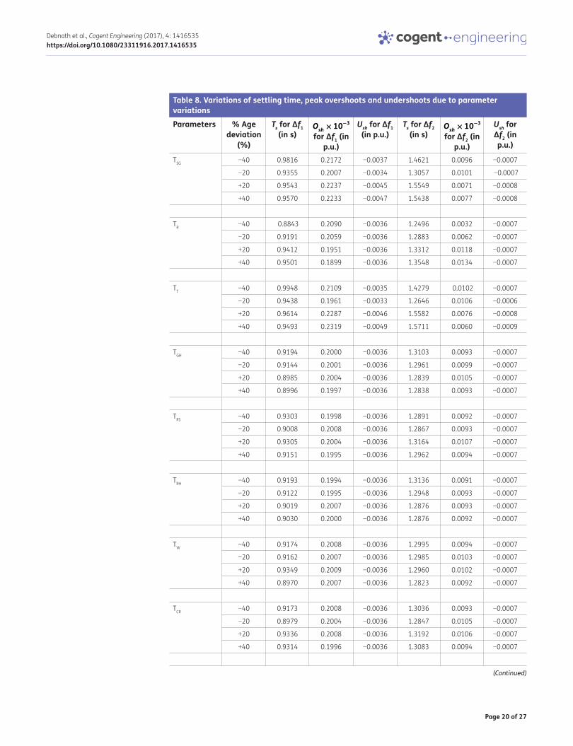
5.4. Analysis of the scrutinized system without HVDC link under parameter variationsThe specified values of parameters of the multi-source system are considered from the appendix (Sahu et al., 2016).The system is further put to test by increasing and decreasing all the time con-stants of the systems by 10%. Under such conditions the deviation of frequency in area 1 (Δf
1) is
presented in the Figure 11. It is observed that the system stability remains unaffected even if the time constant parameters of the system are changed. In order to show the robustness, all the time
Figure 5. Deviation of frequency in Aea 1 and Area 2 without any controller.
0 5 10 15 20 25 30-0.015
-0.01
-0.005
0
Time (in sec)
Freq
uenc
y de
viat
ion
(in H
z)
Area 1Area 2

Page 12 of 27
Debnath et al., Cogent Engineering (2017), 4: 1416535https://doi.org/10.1080/23311916.2017.1416535
Tabl
e 2.
Sca
ling
para
met
ers
of d
iffer
ent c
ontr
olle
rs w
ith A
C lin
k on
lyCO
NTRO
LLER
Ther
mal
Hy
dro
Gas
F 1F 2
F 3F 4
F PF D
F 1F 2
F 3F 4
F PF D
F 1F 2
F 3F 4
F PF D
PD- F
UZZY
-PID
3.90
76
0.10
00
2.02
78
3.99
973.
9999
3.99
980.
1000
0.
1685
0.
1000
0.
1000
3.
9996
0.10
00
1.25
94
3.99
970.
1000
0.
1000
3.
1456
3.
9997
F 1F 2
F 3F 4
F 1F 2
F 3F 4
F 1F 2
F 3F 4
FUZZ
Y-PI
D (S
ahu
et a
l., 2
016)
1.99
851.
9874
1.96
791.
9926
0.10
021.
1278
0.10
320.
7264
1.97
821.
0734
1.97
901.
6516
F pF i
F dF p
F iF d
F pF i
F d
PID
(Moh
anty
et
al.,
201
4b)
0.77
90.
2762
0.68
940.
5805
0.22
910.
7079
0.50
230.
9529
0.65
69

Page 13 of 27
Debnath et al., Cogent Engineering (2017), 4: 1416535https://doi.org/10.1080/23311916.2017.1416535
coefficient parameters are perturbed in a step of 20% and the corresponding values of settling time, peak overshoots and undershoot for frequency deviations (Δf
1) and (Δf
2)are itemized in Table 8.
This table justifies that even after changing the parameters of the system, there is no significance change in the time response specifications which in turn reflects the superior behaviour of the pro-posed controller.
5.5. Analysis of the system without HVDC link under random loading conditionFurther the analysis of the proposed system is extended by applying random loading in area 1. The pattern of random loading is shown in the Figure 12(a). With this random loading, the frequency deviations (Δf
1) and (Δf
2), tie-line power deviations (ΔPtie)are shown in Figure 12(b), (c) and (d) re-
spectively. These figures justify the capacity of the proposed controller to maintain stability even after random load changes.
5.6. Performance indices of proposed system without HVDC linkThe supremacy of the proposed control scheme is tested by computing the values of various perfor-mance indices of the system (with AC tie-line only) namely integral absolute error (IAE), integral time absolute error (ITAE), integral squared error (ISE) and integral time squared error (ITSE). The
Figure 6(a). Deviation of frequency in area 1 due to 1% SLP in area 1 with AC line only.
Figure 6(b). Deviation of frequency in area 2 due to 1% SLP in area 1 with AC line only.

Page 14 of 27
Debnath et al., Cogent Engineering (2017), 4: 1416535https://doi.org/10.1080/23311916.2017.1416535
Figure 6(c). Deviation of tie-line power due to 1% SLP in area 1 with AC line only.
Table 3. Settling time, peak overshoots and undershoots of the response considering AC tie-lines onlyControllers Δf1 Δf2 ΔPtie
Ts in sec
Osh in Hz (10−3)
Ush in Hz (10−3)
Ts in sec
Osh in Hz (10−3)
Ush in Hz (10−3)
Ts in sec
Osh in pu (10−3)
Ush in pu (10−3)
PD- FUZZY-PID 0.9155 0.2007 −3.6 1.2978 0.0105 −0.7 0.8245 0.0070 −0.3
PID Mohanty et al. (2014b)
13.804 2.0 −26.4 8.3560 0.7379 −22.0 9.3032 0.1938 −4.8
FUZZY-PID SAHU et al. (2016)
5.26 0.5510 −8.9579 2.96 0.2119 −3.0119 2.36 0.0826 −0.9653
Figure 7(a). Bar plot of settling time with AC tie-line only.

Page 15 of 27
Debnath et al., Cogent Engineering (2017), 4: 1416535https://doi.org/10.1080/23311916.2017.1416535
system performance increases if the value of these performance indices decreases. These perfor-mance indices are defined below.
(20)IAE =
t
∫0
(||Δf1|| + ||Δf2|| + ||ΔPtie||).dt
Figure 7(c). Bar plot of peak undershoot with AC tie-line only.
Table 4. Percentage improvement in settling time, peak overshoots and under shoots with AC tie-lines onlyControllers Δf1 Δf2 ΔPtie
Ts Osh Ush Ts Osh Ush Ts Osh Ush
PD-FUZZY-PID Compared with PID (Mohanty et al., 2014b)
93.36 89.96 86.36 84.46 98.57 96.81 91.13 96.38 93.75
PD-FUZZY-PID Compared with FUZZY-PID (Sahu et al., 2016)
82.59 63.57 59.81 56.15 95.04 76.75 65.06 91.52 68.92
Figure 8. Block diagram of two area system connected by HVAC and HVDC tie-line. AREA 1 AREA 2
IR
HVDC LINK
HVAC TIE-LINE
Rectifier Station Inverter Station
Figure 7(b). Bar plot of peak overshoot with AC tie-line only.

Page 16 of 27
Debnath et al., Cogent Engineering (2017), 4: 1416535https://doi.org/10.1080/23311916.2017.1416535
Tabl
e 5.
Sca
ling
para
met
ers
of d
iffer
ent c
ontr
olle
rs w
ith H
VDC
link
Cont
rolle
rTh
erm
alHy
dro
Gas
F 1F 2
F 3F 4
F PF D
F 1F 2
F 3F 4
F PF D
F 1F 2
F 3F 4
F PF D
PD- F
UZZY
-PI
D2.
6276
0.
1000
3.
9996
2.26
26
3.99
971.
1541
3.
5442
1.
0520
0.
1000
3.
4119
1.
9636
0.
1000
1.
8606
0.
1000
0.
6111
0.
1000
0.
1000
3.
9998
F 1F 2
F 3F 4
F 1F 2
F 3F 4
F 1F 2
F 3F 4
FUZZ
Y-PI
D(Sa
hu
et a
l., 2
016)
1.99
95
1.98
89
1.99
75
1.98
29
0.96
68
1.29
13
0.10
01
1.99
88
1.99
69
1.19
82
1.98
67
1.98
82
F pF i
F dF p
F iF d
F pF i
F d
PID
(Moh
anty
et
al.,
201
4b)
1.69
29
1.99
23
0.82
69
1.77
731
0.70
91
0.43
55
0.90
94
1.94
25
0.25
13

Page 17 of 27
Debnath et al., Cogent Engineering (2017), 4: 1416535https://doi.org/10.1080/23311916.2017.1416535
(21)ITAE =
t
∫0
(||Δf1|| + ||Δf2|| + ||ΔPtie||).t.dt
(22)ISE =
t
∫0
(||Δf1|| + ||Δf2|| + ||ΔPtie||)2.dt
Table 6. Settling time, peak overshoots and undershoots of the response considering AC-DC tie-lineControllers Δf1 Δf2 ΔPtie
Ts in s Osh in Hz (10−3)
Ush in Hz (10−3)
Ts in s Osh in Hz (10−3)
Ush in Hz (10−3)
Ts in s Osh in pu (10−3)
Ush in pu (10−3)
PD- FUZZY-PID 0.6853 0.2391 −5.4 0.9173 0.0332 −0. 7 1.2946 0.0235 −0. 4
PID (Mohanty et al., 2014b)
3.1789 0.3781 −11.7 13.3306 0.5489 −2.5 9.8765 0.5466 −1.8
FUZZY-PID (Sahu et al., 2016)
1.85 0.2809 −6.7244 4.15 0.2084 −1.4021 2.55 0.1353 −0.7292
Table 7. Percentage improvement in settling time, peak overshoots and undershoots with HVDC linkControllers Δf1 Δf2 ΔPtie
Ts Osh Ush Ts Osh Ush Ts Osh Ush
PD-FUZZY-PID Compared with PID (Mohanty et al., 2014b)
78.44 36.76 53.84 93.11 93.95 72.00 86.89 95.70 77.77
PD-FUZZY-PID Compared with FUZZY-PID (Sahu et al., 2016)
62.95 14.88 19.69 77.89 80.06 50.07 49.23 82.63 45.14
Figure 9(a). Deviation of frequency in area 1 due to 1% SLP in area 1 with AC-DC tie-lines.

Page 18 of 27
Debnath et al., Cogent Engineering (2017), 4: 1416535https://doi.org/10.1080/23311916.2017.1416535
The values of these performance indices are listed in Table 9 for various control techniques. It is clear from the table that the values of these performance indices are less for the proposed hybrid GWO-TLBO optimized PD-Fuzzy-PID controller as compared to other methods.
6. Modelling the system with UPFCUPFC is one of the most widely accepted FACTS devices and is employed to improve the power flow in power system in a more flexible way. This power electronic based device is mainly used to improve the power transfer capability, the power quality issues and the transient stability in the power sys-tem. The connection of UPFC in a two area system is shown in the Figure 13(a). Here Vs, Vr and Vse represents the sending end voltage, receiving end voltage and series compensated voltage respec-tively. The shunt converter adjusts the suitable value of the shunt branch current by injecting suita-ble shunt voltage Vsh such that the real power demand of series converter is fulfilled. The series
(23)ITSE =
t
∫0
(||Δf1|| + ||Δf2|| + ||ΔPtie||)2.t.dt
Figure 9(b). Deviation of frequency in area 2 due to 1% SLP in area 1 with AC-DC tie-lines.
Figure 9(c). Deviation of tie-line power due to 1% SLP in area 1 with AC-DC tie-lines.

Page 19 of 27
Debnath et al., Cogent Engineering (2017), 4: 1416535https://doi.org/10.1080/23311916.2017.1416535
compensated voltage Vse can be adjusted both by the magnitude and angle so that the complex power at the receiving end can be controlled. From the figure the complex power at the receiving end can be expressed as
(24)P − jQ = V∗
r Iline = V∗
r
{(Vs + Vse − Vr)
jX
}
Figure 10. Deviation of frequency in area 1 due to change of SLP in area 1 with Ac tie-line only.
0 2 4 6 8 10 12 14 16 18 20-18
-16
-14
-12
-10
-8
-6
-4
-2
0
2x 10
-3
Time in sec
f 1 in h
ertz
1% SLP2% SLP3% SLP
∆
Figure 11. Deviation of frequency of area 1 due to parameter variations with Ac tie-line only.
0 1 2 3 4 5 6 7-4.5
-4
-3.5
-3
-2.5
-2
-1.5
-1
-0.5
0
0.5x 10
-3
Time in sec
f 1 in h
ertz
Nominal values
Icreased by 10%
Decreased by 10%
∆
Page 20 of 27
Debnath et al., Cogent Engineering (2017), 4: 1416535https://doi.org/10.1080/23311916.2017.1416535
Table 8. Variations of settling time, peak overshoots and undershoots due to parameter variationsParameters % Age
deviation (%)
Ts for Δf1 (in s)
Osh× 10
−3 for Δf1 (in
p.u.)
Ush for Δf1 (in p.u.)
Ts for Δf2 (in s)
Osh× 10
−3 for Δf2 (in
p.u.)
Ush for Δf2 (in p.u.)
TSG −40 0.9816 0.2172 −0.0037 1.4621 0.0096 −0.0007
−20 0.9355 0.2007 −0.0034 1.3057 0.0101 −0.0007
+20 0.9543 0.2237 −0.0045 1.5549 0.0071 −0.0008
+40 0.9570 0.2233 −0.0047 1.5438 0.0077 −0.0008
TR −40 0.8843 0.2090 −0.0036 1.2496 0.0032 −0.0007
−20 0.9191 0.2059 −0.0036 1.2883 0.0062 −0.0007
+20 0.9412 0.1951 −0.0036 1.3312 0.0118 −0.0007
+40 0.9501 0.1899 −0.0036 1.3548 0.0134 −0.0007
TT −40 0.9948 0.2109 −0.0035 1.4279 0.0102 −0.0007
−20 0.9438 0.1961 −0.0033 1.2646 0.0106 −0.0006
+20 0.9614 0.2287 −0.0046 1.5582 0.0076 −0.0008
+40 0.9493 0.2319 −0.0049 1.5711 0.0060 −0.0009
TGH −40 0.9194 0.2000 −0.0036 1.3103 0.0093 −0.0007
−20 0.9144 0.2001 −0.0036 1.2961 0.0099 −0.0007
+20 0.8985 0.2004 −0.0036 1.2839 0.0105 −0.0007
+40 0.8996 0.1997 −0.0036 1.2838 0.0093 −0.0007
TRS −40 0.9303 0.1998 −0.0036 1.2891 0.0092 −0.0007
−20 0.9008 0.2008 −0.0036 1.2867 0.0093 −0.0007
+20 0.9305 0.2004 −0.0036 1.3164 0.0107 −0.0007
+40 0.9151 0.1995 −0.0036 1.2962 0.0094 −0.0007
TRH −40 0.9193 0.1994 −0.0036 1.3136 0.0091 −0.0007
−20 0.9122 0.1995 −0.0036 1.2948 0.0093 −0.0007
+20 0.9019 0.2007 −0.0036 1.2876 0.0093 −0.0007
+40 0.9030 0.2000 −0.0036 1.2876 0.0092 −0.0007
TW −40 0.9174 0.2008 −0.0036 1.2995 0.0094 −0.0007
−20 0.9162 0.2007 −0.0036 1.2985 0.0103 −0.0007
+20 0.9349 0.2009 −0.0036 1.2960 0.0102 −0.0007
+40 0.8970 0.2007 −0.0036 1.2823 0.0092 −0.0007
TCR −40 0.9173 0.2008 −0.0036 1.3036 0.0093 −0.0007
−20 0.8979 0.2004 −0.0036 1.2847 0.0105 −0.0007
+20 0.9336 0.2008 −0.0036 1.3192 0.0106 −0.0007
+40 0.9314 0.1996 −0.0036 1.3083 0.0094 −0.0007
(Continued)

Page 21 of 27
Debnath et al., Cogent Engineering (2017), 4: 1416535https://doi.org/10.1080/23311916.2017.1416535
From the expression, it is clear that Vse = 0 corresponds to an uncompensated system. In this case the UPFC is mainly used in association with the tie-line in order to improve the frequency profile of the system. The transfer function of the UPFC controller employed in AGC (Pradhan et al., 2016) can be expressed by
(25)ΔPUPFC(s) =
{1
1 + sTUPFC
}ΔF(s)
Figure 12(a). Random loading pattern for area 1 considering AC tie-line only.
0 10 20 30 40 50 60 70 80 90 100-0.02
-0.015
-0.01
-0.005
0
0.005
0.01
0.015
0.02
0.025
0.03
Time in sec
Load
ing
in p
u
Table 8. (Continued)Parameters % Age
deviation (%)
Ts for Δf1 (in s)
Osh× 10
−3 for Δf1 (in
p.u.)
Ush for Δf1 (in p.u.)
Ts for Δf2 (in s)
Osh× 10
−3 for Δf2 (in
p.u.)
Ush for Δf2 (in p.u.)
TF −40 0.9260 0.2016 −0.0036 1.3127 0.0108 −0.0007
−20 0.9247 0.1997 −0.0036 1.3099 0.0094 −0.0007
+20 0.9318 0.2005 −0.0036 1.2894 0.0101 −0.0007
+40 0.9315 0.2000 −0.0036 1.3083 0.0089 −0.0007
TCD −40 0.9190 0.2001 −0.0036 1.3119 0.0113 −0.0007
−20 0.9119 0.1991 −0.0036 1.2920 0.0095 −0.0007
+20 0.9295 0.1999 −0.0036 1.3153 0.0092 −0.0007
+40 0.9253 0.1996 −0.0036 1.3172 0.0091 −0.0007
TPS −40 1.0747 0.2866 −0.0062 1.9712 0.0089 −0.0011
−20 0.9839 0.2308 −0.0046 1.5912 0.0099 −0.0008
+20 0.9104 0.1928 −0.0034 1.2365 0.0090 −0.0006
+40 0.9535 0.2056 −0.0037 1.3541 0.0080 −0.0007

Page 22 of 27
Debnath et al., Cogent Engineering (2017), 4: 1416535https://doi.org/10.1080/23311916.2017.1416535
Where TUPFC stands for the time constant of UPFC. ΔF(s) indicates the change of frequency, acts as input to the UPFC and ΔPUPFC(s) indicates the power variation introduced by UPFC in the tie-line, acts as output of the UPFC. The UPFC is placed in multi-source system for both conditions, i.e. without HVDC link and with HVDC link. In the first case with the existing controller gains of suggested PD-Fuzzy-PID controller and AC tie-line, UPFC is placed in series with tie line (Pradhan et al., 2016) and frequency deviations are examined. The Figure 13(b) represents the frequency deviations of area 1
Figure 12(b). Deviation of frequency of area 1 due to random loading.
Figure 12(c). Deviation of frequency of area 2 due to random loading.
Figure 12(d). Deviation of tie-line power due to random loading.

Page 23 of 27
Debnath et al., Cogent Engineering (2017), 4: 1416535https://doi.org/10.1080/23311916.2017.1416535
under such conditions which reveals that with the placement of UPFC the frequency deviations is being improved in consideration of settling time, peak overshoots and undershoots. In the second case the analysis is carried on the multi-source system with HVDC link and UPFC and the frequency deviations of area 1 is depicted in Figure 13(c), which again assists the improvement of the results.
Table 9. The value of various performance indicesIAE ITAE ISE ITSE
PD- FUZZY-PID 0.0047 0.0084 0.0000 0.0000
PID (Mohanty et al., 2014b) 0.1318 0.6013 0.0014 0.0022
FUZZY-PID (Sahu et al., 2016) 0.0195 0.0345 0.0000 0.0000
Figure 13(a). Connection of UPFC in a two area system.
Figure 13(b). Deviation of frequency of area 1 with UPFC and AC tie-line.
0 2 4 6 8 10-4
-3.5
-3
-2.5
-2
-1.5
-1
-0.5
0
0.5x 10 -3
Time in sec
f 1 in h
ertz Without UPFC
with UPFC
∆

Page 24 of 27
Debnath et al., Cogent Engineering (2017), 4: 1416535https://doi.org/10.1080/23311916.2017.1416535
7. ConclusionThe hybrid GWO-TLBO technique is successfully employed in this research article to get the finest factors of the novel PD-fuzzy-PID cascaded controller for automatic generation control of the con-ventional hybrid-source unified power system. Hybrid GWO-TLBO algorithm took the advantages of both GWO and TLBO techniques in order to obtain minimum fitness value. The developed hybrid GWO-TLBO technique is applied to tune the PD-fuzzy-PID cascaded controller in the system without and with HVDC link. The system responses are examined by considering the previously published results like DE optimized PID controller and LUS-TLBO optimized fuzzy-PID controller. With reference to the time response indices like minimum undershoots, settling time and maximum overshoots, the supremacy of the proposed method is established. The robustness and sensitivity of the system is analysed by changing the size and position of SLP. Thereafter, the system robustness is also checked by varying the parameters of the system and by applying random loading in the system. Finally, the system dynamics are evaluated with an UPFC in the system which again affirms the superiority of the suggested controller. In our present research analysis we limited the application of the novel PD-Fuzzy-PID cascaded controller in the conventional multi-source system which can be further extended to renewable source systems and microgrids for automatic generation control.
NomenclatureAGC Automatic generation control
UPFC Unified power flow controller
FACTS Flexible AC transmission system
ITAE Integral time absolute error
HVDC High voltage direct current
ACE Area control error
Bi Frequency bias coefficient
T12 Tie line power coefficient
Ri Regulation time constant
a12 Capacity ratio of control area
KT Thermal unit participation factors
Figure 13(c). Deviation of frequency of area 1 with UPFC and AC-DC tie-line.
0 2 4 6 8 10-6
-5
-4
-3
-2
-1
0
1x 10
-3
Time in sec
f 1 in h
ertz
Without UPFC
With UPFC∆

Page 25 of 27
Debnath et al., Cogent Engineering (2017), 4: 1416535https://doi.org/10.1080/23311916.2017.1416535
KH Hydro unit participation factors
KG Participation factors for gas
KPS Control area gain
TPS Control area time constant
TSG Governor time constant
TT Turbine time constant
KR Reheat gain
TR Reheat time constant
TGH Time constant of speed governor of hydro turbine
TRS Reset time of hydro turbine speed governor
TRH Transient droop time constant of hydro turbine speed governor
TW Rated starting time of water in penstock
bg Constant of valve positioner for gas turbine
cg Valve positioner of gas turbine
YG Gas turbine speed governor lag time constant
XG Gas turbine speed governor lead time constant
TCR Time delay of gas turbine combustion reaction
TF Fuel time constant of gas turbine
TCD Compressor discharge volume—time constant of gas turbine
KDC HVDC link gain
TDC HVDC link time constant
FundingThe authors received no direct funding for this research.
Author detailsManoj Kumar Debnath1
E-mail: [email protected] ID: http://orcid.org/0000-0003-4752-7152Tarakanta Jena1
E-mail: [email protected] Kumar Mallick1
E-mail: [email protected] Department of Electrical Engineering, Siksha ‘O’ Anusandhan
University, Bhubaneswar, 751030, Odisha, India.
Citation informationCite this article as: Optimal design of PD-Fuzzy-PID cascaded controller for automatic generation control, Manoj Kumar Debnath, Tarakanta Jena & Ranjan Kumar Mallick, Cogent Engineering (2017), 4: 1416535.
ReferencesAlomoush, M. I. (2010). Load frequency control and automatic
generation control using fractional-order controllers. Electrical Engineering, 91(7), 357–368. https://doi.org/10.1007/s00202-009-0145-7
Arya, Y. (2017). AGC performance enrichment of multi-source hydrothermal gas power systems using new optimized FOFPID controller and redox flow batteries. Energy, 127, 704–715. https://doi.org/10.1016/j.energy.2017.03.129
Arya, Y., & Kumar, N. (2016a). Optimal AGC with redox flow batteries in multi-area restructured power systems. Engineering Science and Technology, an International
Journal, 19(3), 1145–1159. https://doi.org/10.1016/j.jestch.2015.12.014
Arya, Y., & Kumar, N. (2016b). AGC of a multi-area multi-source hydrothermal power system interconnected via AC/DC parallel links under deregulated environment. International Journal of Electrical Power & Energy Systems, 75, 127–138. https://doi.org/10.1016/j.ijepes.2015.08.015
Arya, Y., & Kumar, N. (2016c). Fuzzy gain scheduling controllers for AGC of two-area interconnected electrical power systems. Electric Power Components and Systems, 44(7), 737–751. https://doi.org/10.1080/15325008.2015.1131765
Cohn, N. (1956). Some aspects of tie-line bias control on interconnected power systems. IEEE Transactions on Power Apparatus and Systems, 1956, 1415–1436.
El-Hameed, M. A., & El-Fergany, A. A. (2016). Water cycle algorithm-based load frequency controller for interconnected power systems comprising non-linearity. IET Generation, Transmission & Distribution, 10(15), 3950–3961. https://doi.org/10.1049/iet-gtd.2016.0699
Ghoshal, S. P. (2004). Optimizations of PID gains by particle swarm optimizations in fuzzy based automatic generation control. Electric Power Systems Research, 72(3), 203–212. https://doi.org/10.1016/j.epsr.2004.04.004
Ghoshal, S. P., & Goswami, S. K. (2003). Application of GA based optimal integral gains in fuzzy based active power-frequency control of non-reheat and reheat thermal generating systems. Electric Power Systems Research, 67(2), 79–88. https://doi.org/10.1016/S0378-7796(03)00087-7
Guha, D., Roy, P. K., & Banerjee, S. (2016). Load frequency control of interconnected power system using grey wolf optimization. Swarm and Evolutionary Computation, 27, 97–115.

Page 26 of 27
Debnath et al., Cogent Engineering (2017), 4: 1416535https://doi.org/10.1080/23311916.2017.1416535
Ismayil, C., Kumar, R. S., & Sindhu, T. K. (2015). Optimal fractional order PID controller for automatic generation control of two-area power systems. International Transactions on Electrical Energy Systems, 25(12), 3329–3348.
Khuntia, S. R., & Panda, S. (2012). Simulation study for automatic generation control of a multi-area power system by ANFIS approach. Applied Soft Computing, 12(1), 333–341. https://doi.org/10.1016/j.asoc.2011.08.039
Kothari, M. L., & Nanda, J. (1988). Application of optimal control strategy to automatic generation control of a hydrothermal system. IEE Proceedings D Control Theory and Applications, 135(4), 268–274. https://doi.org/10.1049/ip-d.1988.0037
Kundur, P. (1994). Power system stability and control. New York, NY: McGraw-Hill.
Lal, Deepak Kumar, & Barisal, A. K. (2017). Comparative performances evaluation of FACTS devices on AGC with diverse sources of energy generation and SMES. Cogent Engineering, 4(1), 1318466.
Manoj Kumar Debnath, R. K., Mallick, S. D., & Aman, A. (2016). Gravitational search algorithm (GSA) optimized fuzzy-PID controller design for load frequency control of an interconnected multi-area power system. 2016 International Conference on Circuit, Power and Computing Technologies (ICCPCT), IEEE.
Mirjalili, S., Mirjalili, S. M., & Lewis, A. (2014). Grey wolf optimizer. Advances in Engineering Software, 69, 46–61. https://doi.org/10.1016/j.advengsoft.2013.12.007
Mohanty, B., Panda, S., & Hota, P. K. (2014a). Differential evolution algorithm based automatic generation control for interconnected power systems with non-linearity. Alexandria Engineering Journal, 53(3), 537–552. https://doi.org/10.1016/j.aej.2014.06.006
Mohanty, B., Panda, S., & Hota, P. K. (2014b). Controller parameters tuning of differential evolution algorithm and its application to load frequency control of multi-source power system. International Journal of Electrical Power & Energy Systems, 54, 77–85. https://doi.org/10.1016/j.ijepes.2013.06.029
Mudi, K. R., & Pal, R. N. (1999). A robust self-tuning scheme for PI-and PD-type fuzzy controllers. IEEE Transactions on Fuzzy Systems, 7(1), 2–16. https://doi.org/10.1109/91.746295
Nanda, J., Mangla, A., & Suri, S. (2006). Some new findings on automatic generation control of an interconnected hydrothermal system with conventional controllers. IEEE Transactions on Energy Conversion, 21(1), 187–194. https://doi.org/10.1109/TEC.2005.853757
Nanda, J., Mishra, S., & Saikia, L. C. (2009). Maiden application of bacterial foraging-based optimization technique in multiarea automatic generation control. IEEE Transactions on Power Systems, 24(2), 602–609. https://doi.org/10.1109/TPWRS.2009.2016588
Nanda, J., & Saikia, L. C. (2008). Comparison of performances of several types of classical controller in automatic generation control for an interconnected multi-area thermal system. Power Engineering Conference, 2008. AUPEC’08, Australasian Universities. IEEE.
Ou, T.-C. (2012). A novel unsymmetrical faults analysis for microgrid distribution systems. International Journal of Electrical Power & Energy Systems, 43(1), 1017–1024. https://doi.org/10.1016/j.ijepes.2012.05.012
Ou, T.-C. (2013). Ground fault current analysis with a direct building algorithm for microgrid distribution. International Journal of Electrical Power & Energy Systems, 53, 867–875. https://doi.org/10.1016/j.ijepes.2013.06.005
Ou, T.-C., & Hong, C.-M. (2014). Dynamic operation and control of microgrid hybrid power systems. Energy, 66, 314–323. https://doi.org/10.1016/j.energy.2014.01.042
Ou, T.-C., Lu, K.-H., & Huang, C.-J. (2017). Improvement of transient stability in a hybrid power multi-system using a designed NIDC (Novel Intelligent Damping Controller). Energies, 10(4), 488. https://doi.org/10.3390/en10040488
Padhy, S., Panda, S., & Mahapatra, S. (2017). A modified GWO technique based cascade PI-PD controller for AGC of power systems in presence of Plug in Electric Vehicles. Engineering Science and Technology, an International Journal, 20(2), 427–442. https://doi.org/10.1016/j.jestch.2017.03.004
Sahu, B. K., Pati, S., & Panda, S. (2014). Hybrid differential evolution particle swarm optimization optimized fuzzy proportional–integral derivative controller for automatic generation control of interconnected power system. IET Generation, Transmission & Distribution, 8(11), 1789–1800. https://doi.org/10.1049/iet-gtd.2014.0097
Pradhan, P. C., Sahu, R. K., & Panda, S. (2016). Firefly algorithm optimized fuzzy PID controller for AGC of multi-area multi-source power systems with UPFC and SMES. Engineering Science and Technology, an International Journal, 19(1), 338–354.
Rao, R. V., Savsani, V. J., & Vakharia, D. P. (2012). Teaching–learning-based optimization: An optimization method for continuous non-linear large scale problems. Information Sciences, 183(1), 1–15. https://doi.org/10.1016/j.ins.2011.08.006
Rout, U. K., Sahu, R. K., & Panda, S. (2013). Design and analysis of differential evolution algorithm based automatic generation control for interconnected power system. Ain Shams Engineering Journal, 4(3), 409–421. https://doi.org/10.1016/j.asej.2012.10.010
Sahu, R. K., Panda, S., & Padhan, S. (2014). Optimal gravitational search algorithm for automatic generation control of interconnected power systems. Ain Shams Engineering Journal, 5(3), 721–733.
Sahu, R. K., Gorripotu, T. S., & Panda, S. (2016). Automatic generation control of multi-area power systems with diverse energy sources using teaching learning based optimization algorithm. Engineering Science and Technology, an International Journal, 19(1), 113–134.
Sahu, B. K., Pati, T. K., Nayak, J. R., Panda, S., & Kar, S. K. (2016). A novel hybrid LUS–TLBO optimized fuzzy-PID controller for load frequency control of multi-source power system. International Journal of Electrical Power & Energy Systems, 74, 58–69. https://doi.org/10.1016/j.ijepes.2015.07.020
Shabani, H., Vahidi, B., & Ebrahimpour, M. (2013). A robust PID controller based on imperialist competitive algorithm for load-frequency control of power systems. ISA Transactions, 52(1), 88–95. https://doi.org/10.1016/j.isatra.2012.09.008
Singh, O., & Nasiruddin, I. (2016). Optimal AGC regulator for multi-area interconnected power systems with parallel AC/DC links. Cogent Engineering, 3(1), 1209272.
Singh, O., & Nasiruddin, I. (2016). Hybrid evolutionary algorithm based fuzzy logic controller for automatic generation control of power systems with governor dead band non-linearity. Cogent Engineering, 3(1), 1161286.
Wang, Y., Zhou, R., & Wen, C. (1994). New robust adaptive load-frequency control with system parametric uncertainties. IEE Proceedings-Generation, Transmission and Distribution, 141(3), 184–190. https://doi.org/10.1049/ip-gtd:19949757
Yousef, H. A., Khalfan, A. K., Albadi, M. H., & Hosseinzadeh, N. (2014). Load frequency control of a multi-area power system: An adaptive fuzzy logic approach. IEEE Transactions on Power Systems, 29(4), 1822–1830. https://doi.org/10.1109/TPWRS.2013.2297432

Page 27 of 27
Debnath et al., Cogent Engineering (2017), 4: 1416535https://doi.org/10.1080/23311916.2017.1416535
AppendixNominal value of the parameters of conventional hybrid-source system (Sahu et al., 2016).
f = 60 Hz; RG = RHY = RTH = 2.4 Hz/p.u.MW; B1 = B2 = 0.4312p.u.MW/Hz; KT = 0.543478; KH = 0.326084; KG = 0.130438; TR = 10s; Tsg = 0.08S; KR = 0.3; TRS = 5; TW = 1S; bg = 0.05; cg = 1; TGH = 0.2S; TRH = 28.75S; XG = 0.6; YG = 1; TCR = 0.01S; TF = 0.23S; TCD = 0.2S; TPS = 11.49S; KPS = 68.9566; Tdc = 0.2S; Kdc = 1; T12 = 0.0433; a12 = −1.
© 2017 The Author(s). This open access article is distributed under a Creative Commons Attribution (CC-BY) 4.0 license.You are free to: Share — copy and redistribute the material in any medium or format Adapt — remix, transform, and build upon the material for any purpose, even commercially.The licensor cannot revoke these freedoms as long as you follow the license terms.
Under the following terms:Attribution — You must give appropriate credit, provide a link to the license, and indicate if changes were made. You may do so in any reasonable manner, but not in any way that suggests the licensor endorses you or your use. No additional restrictions You may not apply legal terms or technological measures that legally restrict others from doing anything the license permits.
Cogent Engineering (ISSN: 2331-1916) is published by Cogent OA, part of Taylor & Francis Group. Publishing with Cogent OA ensures:• Immediate, universal access to your article on publication• High visibility and discoverability via the Cogent OA website as well as Taylor & Francis Online• Download and citation statistics for your article• Rapid online publication• Input from, and dialog with, expert editors and editorial boards• Retention of full copyright of your article• Guaranteed legacy preservation of your article• Discounts and waivers for authors in developing regionsSubmit your manuscript to a Cogent OA journal at www.CogentOA.com