optical splitting trees for high- precision monocular imaging
TRANSCRIPT

Optical Splitting Trees for High-Precision Monocular Imaging
The Harvard community has made thisarticle openly available. Please share howthis access benefits you. Your story matters
Citation McGuire, Morgan, Wojciech Matusik, Hanspeter Pfister, Billy Chen,John F. Hughes, and Shree K. Nayar. 2007. Optical splitting trees forhigh-precision monocular imaging. IEEE Computer Graphics andApplications 27(2): 32-42.
Published Version doi:10.1109/MCG.2007.45
Citable link http://nrs.harvard.edu/urn-3:HUL.InstRepos:4101892
Terms of Use This article was downloaded from Harvard University’s DASHrepository, and is made available under the terms and conditionsapplicable to Other Posted Material, as set forth at http://nrs.harvard.edu/urn-3:HUL.InstRepos:dash.current.terms-of-use#LAA
Computational Photography
32 March/April 2007 Published by the IEEE Computer Society 0272-1716/07/$25.00 © 2007 IEEE
M any computational photography appli-cations require sets of images that are
captured simultaneously from the same viewpoint buthave different image sensors and imaging parameters.In this article, we address the problem of designing effi-cient multisensor cameras that can capture suchimages. Although for two- and three-sensor camerasad-hoc designs are often effective, the design problembecomes challenging as the number of sensors increas-es. We demonstrate results on cameras created usingour new design paradigm that contains as many as eight
sensors. (To gain a better sense ofthe issues we’re tackling in this arti-cle, read the “Basic Background andConsiderations” sidebar.)
In this article, we consider thedesign of monocular multiview opti-cal systems that form optical split-ting trees, where the optical path
topology takes the shape of a tree because of recursivebeam splitting. Designing optical splitting trees is chal-lenging when it requires many views with specific spec-tral properties. We introduce a manual design paradigmfor optical splitting trees and a computer-assisted designtool to create efficient splitting-tree cameras. The toolaccepts as input a specification for each view and a setof weights describing the user’s relative affinity for effi-ciency, measurement accuracy, and economy. An opti-mizer then searches for a design that maximizes theseweighted priorities. Our tool’s output is a splitting-treedesign that implements the input specification and ananalysis of the efficiency of each root-to-leaf path. Auto-matically designed trees appear comparable to thosedesigned by hand; we even show some cases wherethey’re superior.
We’ve previously reviewed and demonstrated captur-ing multiple monocular views in various contexts, butrarely have more than three simultaneous views beencaptured. (To see others’ approaches to this and similar
problems, see the “Related Work” sidebar on page 40.)Our approach makes design, implementation, and cal-ibration practical for many more sensors. To demon-strate the practical application of our splitting treeparadigm and optimizer, we built the configurable opti-cal splitting tree system shown in Figure 1 (on page 34)that captures up to eight views. Assisted by our designtool, we were able to use this single device to implementseveral different popular computational videographyapplications: high-dynamic range (HDR), multifocus,high-speed, and hybrid high-speed multispectral video.In this article, we demonstrate results for each of these.
Optical splitting treesOptical splitting trees are schematic representations
of tree-topology filter systems. The edges are light pathsand the nodes are optical elements. Nodes with a singlechild represent filters and lenses. Nodes with multiplechildren are beam splitters. Leaf nodes are sensors. Theplenoptic field enters the system at the root. The physi-cal path length to each sensor’s optical center is identi-cal. However, a sensor’s tree depth (the number ofinternal nodes between it and the root) might differ.
Figure 2 shows a schematic of a full binary splittingtree, viewed from above, where light enters on the upperright. This layout packs components into a small formfactor with no optical path occluded. The thick blacklines are light baffles preventing the reflective child ofeach splitter from imaging stray light.
Further abstracting the structure and using the sym-bols in Figure 3, we can emphasize the most significantelements. In each case in Figure 3, light enters at the topand emerges at the bottom. Spectral filters are narrowbandpass filters centered at the specified value. “Sensor+ Lens” sets specify imaging properties. The neutraldensity (ND) filter reduces the amount of transmittedlight, equally across all wavelengths. The plate mirrorsplits incoming light into two directions. Unless speci-fied, it reflects 50 percent and transmits 50 percent of
The authors present a designframework and optimizer for computational systemscontaining many sensors on a common optical axis.
Morgan McGuireWilliams College
Wojciech Matusik and Hanspeter PfisterMitsubishi Electric Research Laboratories (MERL)
Billy ChenStanford University
John F. HughesBrown University
Shree K. NayarColumbia University
Optical SplittingTrees for High-PrecisionMonocular Imaging

incident light (“50R/50T”). Dichroic mirrors reflect ortransmit light according to the incident wavelength.Weknow that all paths from the root to the leaves have thesame physical length, so the representation need notpreserve distances. Angles are an artifact of building thephysical system and also need not be represented.
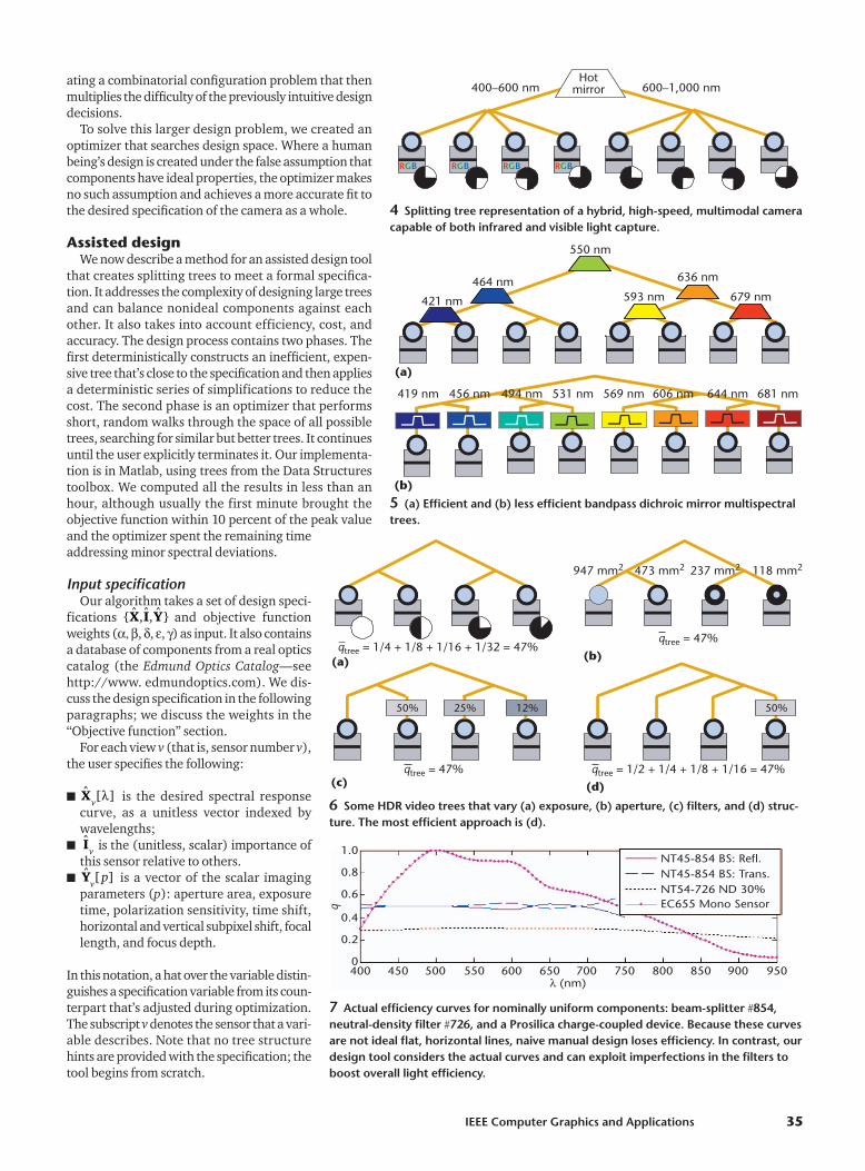
We’re left with an abstraction where only graph topol-ogy is of significance. The tree has a branch factor of atmost two when the beam splitters are plate mirrors (asin our implementation). Other splitting elements canproduce higher-degree nodes. We can collapse subtreesof beam splitters with no intervening filters into a single node representation with many children, as inFigure 4 (on page 35). This representation also abstractsthe nature of the employed splitting element .
Figure 5a shows a balanced multispectral splittingtree. Each beam splitter is a dichroic mirror, whichdivides half the remaining visible spectrum among itschildren so that no light is lost. This is an excellentapproach, except that manufacturing large dichroic mir-
rors is expensive. Figure 5b schematically shows a lessefficient design using readily available bandpass filters(for example, Edmund Optics’ filters NT43-055 throughNT43-088). Each path receives about 1/8 of the inci-dent light, which is bandpass filtered immediatelybefore the lens. Note that both designs are useful; thesplitting-tree concept makes it easy to switch betweenthem if necessary.
Many applications require a balanced binary tree, inwhich each sensor has the same tree depth and the beamsplitters divide incident light evenly between their chil-dren. In others (such as HDR) it’s useful to unbalancethe tree. We may do so either by using beam splitterswith uneven division ratios, or by creating a structural-ly unbalanced tree where the sensors’ tree depths vary.
The two designs that we present each have theiradvantages. Both designs are straightforward ones thatsomeone could construct manually. Other applicationsoffer more alternatives (for example, Figures 5 and 6demonstrate cost and efficiency tradeoffs), or have spec-
IEEE Computer Graphics and Applications 33
Basic Background and Considerations
Why are sets of pixel-aligned images of the same sceneuseful? Consider a set of images with different exposuretimes as an example. Short exposures will capture detail inthe bright areas of a scene, while long exposures will revealdetails in shadows that would otherwise be underexposed.Fitting an intensity curve to only the correctly exposedimages at each pixel fuses the set of images into a singlehigh-dynamic range (HDR) image that captures detaileverywhere. We consider the output computationalbecause the final image isn’t (and can’t be) recorded by anisolated image sensor; a battery of sensors andcomputations produce it. Other popular applications thatrequire multiple images and computations include high-speed, super-resolution, focus/defocus analysis, andmultispectral video.
We say that the image sets contain multiple monocularscene views to distinguish them from stereo and other arraycameras where the optical axis is different for each imager.Working with monocular views is ideal in many contextsbecause the images have direct pixel correspondence.Except for calibration, they don’t need to be warped anddon’t exhibit parallax artifacts with depth.
The cameras that capture multiple monocular views differfrom conventional cameras. A conventional cameracontains a single objective (lens system) and imager. Tocapture multiple views, the camera makes an optical copyof the incident light using a beam splitter, such as a half-silvered mirror.
This lets two imagers each observe the same view at halfintensity. Inserting filters and other optical elements into theoptical path between the beam splitter and the imagerleads to different measurements at the corresponding pixelsin each imager. As with the HDR example, we can combinethese measurements into an image that represents moreinformation (bits) than a single view, allowing for high-precision measurements. The method of combining themeasurements may increase the dynamic range (high-order
bits), the resolution (low-order bits), the number of samplesacquired at different parameters, or some combination.
The amount of useful precisions for a measurement islimited by environmental and sensor noise. The ratio ofmeasured light to incident light is that optical sensor’sefficiency. Efficiency and the intensity of the light sourcedetermine the amount of noise in an optical measurement.Therefore it’s good to design optical systems where a largefraction of light reflected off the subject actually reaches thesensor instead of, for example, being absorbed by filters orlost at lenses through absorption and internal refraction.
When considering a system’s efficiency, it’s useful todiscuss each component’s efficiency—for example, a lensthat absorbs 10 percent of the incident light is only 90percent efficient. Although overall efficiency is desirable,sometimes someone intentionally uses an inefficientcomponent. A common example is a neutral density filter,which modulates overly intense light. Consideringefficiency over the whole spectrum, a band-pass filter is alsointentionally inefficient because it blocks light outside thepass band.
An accurate sensor measures the desired quantity. This isa separate concept from precision. For example, abathroom scale with five decimal places and a brick on topof it measures weight with high precision but low accuracybecause of the brick’s added weight. In contrast, a well-calibrated scale with no decimal places has high accuracybut low precision. To make an optical design accurate wemust match the real-world specifications of componentslike filters and sensors to the theoretically desired ones andcalibrate for common sources of error like elementmisalignment and radial distortion. Of course, componentswith tightly controlled specifications could be prohibitivelyexpensive—economy is often a real limiting factor for bothproducts and research. Design is the process of balancingtheoretical desires, engineering capability, and the fourconcerns of efficiency, accuracy, precision, and economy.

ifications that force tough compromises between desir-able characteristics.
Consider a hypothetical application that requires HDRin the red and near-infrared channels, moderate dynam-ic range across the visible spectrum, and a final catch-allwith low-precision, wide-spectrum measurement (wecould easily envision face recognition applications withsimilar requirements). Furthermore, assume that theideal bit depths of the different channels are all speci-fied by the theory behind this application. Many split-ting trees exist that meet these specifications. Thisimmediately raises nontrivial design questions: Shouldone split the color channels out first? Should the redchannel of the visible spectrum sample be used in theHDR red/infrared, even though it only overlaps partlywith the desired spectral response? Should exposure,aperture, or neutral density (ND) filters be used to cre-ate the HDR trees? Which brand of filter produces theleast light loss?
Like most graphics and vision researchers, we’ve pre-viously answered questions like these by evaluating ahandful of promising straw-man designs and ignoringthe full design space of possibilities. If the tradeoffs areheavily biased (for example, if the budget isn’t a majorfactor, but the signal-to-noise ratio is crucial), it’s notsurprising that we can resolve many design decisionsby intuition. In those cases, we make reasonable ad-hocdecisions.
What is surprising (at least, it was to us) is that manycases exist where intuitive decisions for seemingly sim-ple applications often produce inaccurate cameras. Thiscan be seen by analysis of the splitting tree for errorsources. Figure 7 reveals the primary reason for this.The curves in the figure show the actual spectralresponse, according to the manufacturers, for nominal-ly uniform components like sensors, plate mirrors, andfilters. Ideally, these curves should all be horizontallines. In reality, they’re bumpy curves. This means thata simple design decision like splitting the optical pathhas unintentionally changed the spectral response andrelative efficiency at each sensor.
When several splits, filters, and lenses are combined,these deviations from the theoretically ideal behaviorcreate significant inaccuracy. This inherent spectral inac-curacy leads to problems in other parameters. For exam-ple, if the red channel is too dim because the beamsplitter modulated it unevenly, we must adjust eitherexposure or aperture to compensate. Alternatively, wecould try a different brand of sensor, splitter, filter, orlens. But which of several brands should we use? Evenwhen budgets are flexible, the cost of purchasing pre-cisely uniform components can quickly skyrocketbecause of manufacturing challenges, so most camerasare designed with nonuniform components.
The error introduced by the deviation betweenabstract ideal component behavior and real-world spec-ifications motivates a desire to include the real compo-nent specifications in the design process. Consideringlenses, splitters, and filters, a tree with eight camerascontains dozens of components, some of which areshared over multiple sensors. Adjusting the componentsalong one path affects other downstream sensors, cre-
Computational Photography
34 March/April 2007
1 (a) Top and (b) side images of our generic eight-view splitting treesystem, which can quickly be reconfigured to implement previous capturesystems such as high-dynamic range (HDR) and multispectral video, or tomeet novel applications. The superimposed laser beam shows the recur-sively split optical path.
2 Physicallayout of abalanced eight-view splittingtree. The redlines are beamsplitters andthick black linesare baffles.
Light
600 nm
100 nm2
2 nm
ND filter
Plate mirror
Dichroic mirror
Aperature
Focal depth
Time shift andexposure
30% ND
Sens
or +
lens
3 Lexicon of symbols used in our abstract tree diagrams.
(a)
(b)
ating a combinatorial configuration problem that thenmultiplies the difficulty of the previously intuitive designdecisions.
To solve this larger design problem, we created anoptimizer that searches design space. Where a humanbeing’s design is created under the false assumption thatcomponents have ideal properties, the optimizer makesno such assumption and achieves a more accurate fit tothe desired specification of the camera as a whole.
Assisted designWe now describe a method for an assisted design tool
that creates splitting trees to meet a formal specifica-tion. It addresses the complexity of designing large treesand can balance nonideal components against eachother. It also takes into account efficiency, cost, andaccuracy. The design process contains two phases. Thefirst deterministically constructs an inefficient, expen-sive tree that’s close to the specification and then appliesa deterministic series of simplifications to reduce thecost. The second phase is an optimizer that performsshort, random walks through the space of all possibletrees, searching for similar but better trees. It continuesuntil the user explicitly terminates it. Our implementa-tion is in Matlab, using trees from the Data Structurestoolbox. We computed all the results in less than anhour, although usually the first minute brought theobjective function within 10 percent of the peak valueand the optimizer spent the remaining timeaddressing minor spectral deviations.
Input specificationOur algorithm takes a set of design speci-
fications and objective functionweights (�� �, �, �, �) as input. It also containsa database of components from a real opticscatalog (the Edmund Optics Catalog—seehttp://www. edmundoptics.com). We dis-cuss the design specification in the followingparagraphs; we discuss the weights in the“Objective function” section.
For each view v (that is, sensor number v),the user specifies the following:
■ is the desired spectral responsecurve, as a unitless vector indexed bywavelengths;
■ is the (unitless, scalar) importance ofthis sensor relative to others.
■ is a vector of the scalar imagingparameters (p): aperture area, exposuretime, polarization sensitivity, time shift,horizontal and vertical subpixel shift, focallength, and focus depth.
In this notation, a hat over the variable distin-guishes a specification variable from its coun-terpart that’s adjusted during optimization.The subscript v denotes the sensor that a vari-able describes. Note that no tree structurehints are provided with the specification; thetool begins from scratch.
ˆ [ ]Yv
p
Iv
ˆ [ ]Xv
λ
{ˆ ,ˆ, ˆ }X I Y
IEEE Computer Graphics and Applications 35
4 Splitting tree representation of a hybrid, high-speed, multimodal cameracapable of both infrared and visible light capture.
Hotmirror400–600 nm 600–1,000 nm
RGB RGB RGB RGB
5 (a) Efficient and (b) less efficient bandpass dichroic mirror multispectraltrees.
464 nm 636 nm
550 nm
679 nm593 nm421 nm
419 nm 456 nm 494 nm 531 nm 569 nm 606 nm 681 nm644 nm
(b)
(a)
6 Some HDR video trees that vary (a) exposure, (b) aperture, (c) filters, and (d) struc-ture. The most efficient approach is (d).
50% 50%25% 12%
947 mm2 473 mm2 237 mm2 118 mm2
qtree = 47% qtree = 1/2 + 1/4 + 1/8 + 1/16 = 47%
qtree = 47%qtree = 1/4 + 1/8 + 1/16 + 1/32 = 47%
(a) (b)
(c) (d)
7 Actual efficiency curves for nominally uniform components: beam-splitter �854,neutral-density filter �726, and a Prosilica charge-coupled device. Because these curvesare not ideal flat, horizontal lines, naive manual design loses efficiency. In contrast, ourdesign tool considers the actual curves and can exploit imperfections in the filters toboost overall light efficiency.
EC655 Mono SensorNT54-726 ND 30%NT45-854 BS: Trans.NT45-854 BS: Refl.
400 450 500 550 600 650λ (nm)
700 750 800 850 900 950
1.0
0.8
0.6
0.4
0.2
0
q
EfficiencyEfficiency is a desirable quality in a camera. In this
section, we rigorously define the efficiency q of a cam-era as the fraction of incident light that’s measured bysensors.
The specification dictates how the tree dis-tributes light, but the scale is necessarily relative becauseat input time the light loss inherent in the design isunknown. Likewise, each component in the catalogmust be annotated with a curve describing its transmis-sion (for a filter), split ratio (for a beam splitter), or dig-ital output sensitivity (for a sensor) at severalwavelengths. Figure 7 shows examples of these curves.
We call this curve the quantum efficiency of a com-ponent. We represent it with a vector q[] describing theratio of output to input light at a node, sampled at 12wavelengths between 400 and 950 nanometers (nm).Because our components are passive, q[] 1. In otherwords, the efficiency of a component describes the ratioof light lost as it travels through that component. For aview v, let
over every component i on the path from v to the root.Let scalar be the mean efficiency of that view withrespect to , and let
denote the efficiency of the entire camera. With thesedefinitions, specifies the shape of the desired response and is the scalarfraction of measured light captured by view v.
Objective functionThe optimizer seeks camera designs that maximize
the goals of efficiency, accuracy, and cost. The objectivefunction is the weighted sum of expressions represent-ing each of these goals:
(1)
(2)
(3)
(4)
(5)
These expressions drive the optimizer as follows.
■ Efficiency (Equation 1). Maximize the total lightmeasured (and therefore, the signal-to-noise ratio).
■ Spectral accuracy (Equation 2). Minimize thedifference from the color specification.
■ Relative importance (Equation 3). Ensure thateach sensor receives the correct amount of light rel-ative to other sensors, regardless of overall efficiency
(this is particularly important for applications likeHDR where exposures vary widely).
■ Parameter accuracy (Equation 4). Minimizethe difference from the specified pixel shift, tempo-ral shift, polarization, motion blur, and defocus.
■ Economy (Equation 5). Minimize the purchasecost of components.
Each expression is quadratic to create stable maxima.Recall that X and Y are vectors, so is a dot product,and that the hats denote specification variables.
Greek-letter variables are user-tunable weights, whichmay vary from zero (which ignores a term) to arbitrar-ily large positive numbers (which demand that the opti-mizer exactly meets the specification). They’re all scalarsexcept for , which is a vector so that each imaging para-meter may be weighted independently.
We distinguish between scalar (that is, exposure time)parameters in and the spectral response vector fortwo notational reasons. First, most optical componentsexhibit surprising spectral nonuniformity but are rela-tively controlled along other parameters (see Figure 7).Representing spectral error explicitly is therefore infor-mative. Second, the optimization weight is the same foreach wavelength. We could instead consider the systemto be parameterized only by scalars, where the first 12represent responses at different wavelengths.
We choose initial weights so that each of the fiveexpressions has approximately the same magnitude.(Note that this depends on the units selected for Y.) Theresult quality is most sensitive because preserving accu-racy introduces filters that absorb light. Other weightscan vary within a factor of two without affecting the out-put, since cost and accuracy are less contentious whenmany filter choices are available.
Deterministic phaseThe goal of this phase is to construct a tree that accu-
rately meets the view specifications. To simplify theprocess, economy and efficiency are left unconstrained.The system first groups the views into separate binary trees of similar to increase the later likelihoodof shared filters and then links those trees into a singlelarge tree.
All splitters are 50R/50T plate mirrors at this stage. Tosatisfy the values, the system evaluates the actual Xat each leaf and introduces bandpass filters immediate-ly before the sensors to optimize the spectral accuracyterm. It then sets all parameters as dictated by . Final-ly, it evaluates I at each leaf and inserts ND filters until the the system satisfies the importance accuracyconstraint.
Search phaseFrom the deterministically computed tree we search
for steps in the design space that increase the bojectivefunction obj using the uphill simplex method. Each stepbegins with a randomly chosen transformation. Becausemany transformations require parameter changes to bebeneficial, the Y vectors are adjusted to increase spectraland importance accuracy before obj is evaluated for thealtered tree.
Y
X
X
XY
�ε
| |⋅ 2
− ∑γ ci2
nodes
+ −| ( ˆ )| )�ε Y
v vY 2
+ −| ( ˆ )|δ Iv v
I 2
− −∑ (| ( ˆ )|βviews
Xv v
X 2
obj (tree)=tree
αq
ˆ [ ] /I q qv v
λ =tree
ˆ [ ] [ ]/X q qv v v
λ λ=
q qtree views
=∈∑ vv
qv
q qv ii[ ] [ ]λ λ=
∈∏ path
{ˆ ,ˆ, ˆ }X I Y
Computational Photography
36 March/April 2007
Several transformations preserve x and I while poten-tially reducing the cost of the tree or increasing .These tree identities include the following:
■ no transformation (allows Y change without a treechange);
■ if the same filter appears on both children of a beamsplitter, move it to the parent of the splitter;
■ replace a chain of filters with a single, equivalent fil-ter;
■ reorder the filters in a chain (tends to encourage thesecond and third items);
■ rotate a node, as in Figure 8; and■ replace a splitter and filters on its children with a split-
ter whose R/T ratio approximates the filter ratio
For example, the right rotation transformation in Fig-ure 8 reparents node B. After transformation, the opti-mizer explicitly adjusts the ND filters to maintain the lightratios at qA:qB:qC � 2:1:1. For the left tree, the fractions oflight at the root are 1/4, 1/8, and 1/8. For the right,they’re 1/2, 1/4, and 1/4. Both designs capture the same(relative) measurement, but the right tree is twice as effi-cient. However, spectral filters are expensive and ND fil-ters have negligible cost. The tree on the left is thereforealmost twice as economical as the tree on the right.
Transformations other than the ones that we’ve notedcan change X and I and are therefore less likely toimprove the tree, since the design search begins with atree that is nearly optimal for those variables. Nonethe-less, such transformations provide reachability to theentire design space and therefore allow the optimizerto theoretically find the best tree given sufficient runtime. These transformations include
■ adding, removing, or changing a filter at random;■ rotating a subtree right or left without adding filters;■ replacing a beam splitter at random; and■ swapping two subtrees.
Experimental systemTo test our design framework we built a physical con-
figurable splitting-tree system with eight computervision sensors that use 100 � 100-mm plate-mirror andhot-mirror beam splitters (see Figure 1). We removedthe black baffles in Figure 1a for Figure 1b to make thecameras and light beam more visible from the side. Hotmirrors transmit visible light and reflect infared.
The sensors are Bayer filter A601fc color cameras andmonochrome A601f cameras by Basler. Each sensor isequipped with a Pentax objective. The tree exactly fits ona 2 � 2 square-foot optical breadboard with holes spacedat half-inch intervals. The sensors are connected to asingle 3-GHz Pentium 4 computer using the FireWireinterface. We wired the hardware shutter trigger pinsto each of the eight data pins of the PC parallel port,which we precisely controlled by writing bit masks tothat port through a special Win32 driver (see http://www.logix4u.net/inpout32.htm).
The difficulty of calibration increases with the num-ber of elements. Sensors that share an optical center arealso more difficult to calibrate than array systems where
the views aren’t expected to align perfectly.To calibrate the system, we first orient the plate mir-
ror beam splitters at 45 degrees to the optical axis. Toorient these, we place a lens cap over each camera andshine a laser along the optical axis to illuminate a singlepoint near the center of each lens cap. Working throughthe splitting tree from the root to the leaves, we rotatethe beam splitters until each dot appears exactly in thecenter of the lens cap.
Second, we construct a scene containing a nearby tar-get pattern of five bullseyes on transparent plastic anda distant, enlarged pattern on opaque poster board sothat the two targets exactly overlap in view 1. We thentranslate all other sensors until the target patterns alsooverlap in their views. This ensures that the optical cen-ters are aligned.
Third, we compute a software homography matrix tocorrect any remaining registration error. We find corre-sponding points in 3D by filming the free movement ofa small liquid-eye display (LED) light throughout thescene. Let Cs be the N � 3 matrix whose rows are homo-geneous 2D positions—that is, [x y 1]—of the light cen-troid at subsequent frames in view number v. Thetransformation mapping pixels in view 1 to those in view v is
where denotes a pseudo-inverse. We solve this systemby singular value decomposition because it is frequent-ly ill conditioned. For color calibration, we solve the cor-responding system in color space using pixel valuessampled from a Gretag Macbeth color chart instead of2D positions.
Applications and resultsWe implemented various video capture applications
using a mixture of data acquisition trees that were hand-designed using the framework and ones that the opti-mizer automatically produced. Without our system, itoften takes several days to assemble and calibrate a newcomputational photography camera for a single appli-cation when starting from scratch. Because our hard-ware system is configurable and most splitting treesform subsets of the full tree that we prebuild on the opti-cal table, we can configure for different applicationscomparatively quickly. For each of the examplesdescribed here we reconfigured and calibrated the sys-tem in about two hours, even when outside the labora-tory. Paired with the assisted design tool, this allows formuch greater experimental flexibility than we had pre-viously enjoyed.
In each example, the result figures and videos demon-strate accurate color, temporal, and spatial image cap-
†
H H C C Cv v v v
∗ = − =| ) †arg min(| 1 21
qtree
IEEE Computer Graphics and Applications 37
8 This “right rotation” transformation at the root reparents node B.
A C A B B C
50% 25%

ture, and registration across many moremonocular views than in previous work.
The deterministic phase always pro-duces a viable design, so optimizationwill technically never fail. However, inabout two out of 10 cases, it takes longerto adjust the weights than it would tosimply adjust the output of the determin-istic phase manually. In its current form,the optimizer is therefore most usefulwhen applied to designs with many sen-sors, significantly nonuniform compo-nents, or tricky spectral constraints.
High dynamic rangeFigure 6 shows several splitting trees
for a simple, HDR camera where the rel-ative intensities observed by the views arepowers of two. We designed these byhand based on previous work and verifiedthat with appropriate weights the opti-mizer rediscovered equivalent structures.
In Figure 6a, a large economy weightgives the inexpensive variable
exposure solution.1 The drawbacks of that approach are inconsistentmotion blur between cameras and low
efficiency. Increasingthe exposure weight and decreasing the apertureweight in leads to Figure 6b, where the aperturevaries. Now motion blur is correct but the depth offield varies and is still low.
An alternative is to use ND filters as in Figure 6c, simi-lar to Mitsunaga et al.2 Compared to Debevec and Malik’s1
method, this corrects both motion blur and depth of fieldbut not efficiency. Our optimizer did not rediscover thisapproach—instead it found a better design!
The tree in Figure 6d has . Instead ofblocking light with the iris, shutter, or filters, it redi-rects excess light at a sensor to other sensors that canmeasure it. Aggarwal and Ahuja3 mention a similardesign in passing; however, their design was neverimplemented and we believe that it would have pro-duced undesirable asymmetric point-spread functionsif actually built.
Figure 9 shows results from two HDR experiments.In sequence number one (top), the actor is brightly litand the city lights are dim in the background. Insequence number two (bottom), the actor is inside adark office and the sky and city in the distance arebright. On the right are resulting tone-mapped HDRimages. These combine frames from four different sen-sors to keep all scene elements visible and within thedisplay’s dynamic range.
Multiple focus and defocusWe can use images focused at multiple depths to
recover depth information4-6 and form images with aninfinite7 depth of field. Many systems4 split the viewbehind the lens. Splitting in front of the lens lets us varynot only the location but also the depth of the field bychanging the aperture.
qtree
= 30 32/
�ε
qtree
= 15 32/
γ
Computational Photography
38 March/April 2007
9 Frames from two HDR sequences. Images on the left are four simultaneously captured views. The large images on the right are the corresponding tone-mapped composites.
Captured data Result: Tone-mapped HDR compositesS
eque
nce
2S
eque
nce
1
10 Multifocus images captured by sensors. (a) Eight simultaneous viewswith different focus depths, and (b) a fused infinite depth-of-field result.
(a)
(b)

To capture images with varying depths of field, suchas those in Figure 10, we use a full binary tree with witheight cameras. Each sensor is focused at a differentdepth, ranging from 20 cm from the optical center(about 4 cm from the first beam splitter) to 20 m (effec-tively infinity). We use wide f/1.4 apertures for a nar-row depth of field on each sensor.
Figure 10 shows an artificially wide depth of fieldachieved by a weighted sum of each view. The weightat each pixel is proportional to the local contrast (lumi-nance variance) in the view, squared.
Matting and other designsTwo matting algorithms8,9 from computer graphics
literature use custom cameras that can be expressedwithin our framework. We compare the originally pub-lished designs against new ones created by our optimiz-er from their specifications.
McGuire et al.8 capture three monocular views, eachwith a focal length of f � 50 mm and each at equal impor-tance: a pinhole view with an aperture, and two viewsfocused at different depths. Their design uses two50R/50T beam splitters and two filters.
Given their specifications, the deterministic phase ofour optimizer immediately produced the correct (butinefficient) tree in Figure 11a. The deterministic phaseis constrained to create a full binary tree, place sensorsat leaves from left to right, and then add filters at theleaves to implement the desired specification.
After many iterations the optimizer found a better treeshown in Figure 11b. In this tree, the second split is onthe right, between the two wide-aperture sensors. Thisgives more light to the pinhole sensor and reduces thenumber of ND filters required. Note that the short-passfilter has also propagated up the tree but not yet reachedthe root.
After about 40 minutes, our optimizer appeared tostabilize on the tree design shown in Figure 11c. Com-pared to the originally published design and trees foundon previous iterations, this new design achieves higherefficiency through a 70R/30T beam splitter; a single,weaker ND filter shared across two views to reduce cost;and a short-pass filter to attenuate the color sensors’undesirable infrared response. The optimizer adjustedexposures slightly to compensate for imperfections atthe 50R/50T beam splitter on the right branch, whereit chose a low-quality component to reduce cost. Subse-quent runs produced approximately the same output.Adjusting the input weights traded accuracy in the expo-sure time against accuracy of the aperture size.
We performed a similar experiment on Debevec etal.’s9 matting system that uses a plate mirror and aninfrared filter to capture two monocular views. The opti-mizer simply replaced the half mirror with a hot mirrorto increase efficiency at no additional cost.
The matting cameras are simple. Figure 12 showsthe tree computed for an arbitrary complex specifica-tion. The optimizer correctly created an efficient HDR(c, d, e) subtree. However, it failed to place a hot mirror between (a) and (b), probably because weweighed accuracy much higher than efficiency for thistest. The six plots show how well it did match the
IEEE Computer Graphics and Applications 39
10% ND
20% ND
50% ND 50% ND
10% ND
10% ND
10% ND
16 mm2
3 m
0.002 s
767 mm2
3 m
0.002 s
767 mm2
15 m
0.002 s
16 mm2
3 m
0.019 s
767 mm2
3 m
0.002 s
767 mm2
15 m
0.002 s
16 mm2
3 m
0.018 s
767 mm2
3 m
0.017 s
767 mm2
15 m
0.016 s
Short pass 650 nm (VIS)
Short pass 650 nm (VIS)
70% 30%
(a)
(b)
(c)
11 Mattingcamera basedon McGuire etal.8 at differentstages in thesearch process.(a) After determinsticphase, (b)intermediateresult (approximately30 seconds),and (c) besttree found(approximately40 minutes).The final camera in (c) is superior tothe originallypublished manual design.
55% ND
2% ND
30% ND30%70%
(a) (b) (c) (d) (e) (f)
1.0
0.5
0
0.4
0.2
0
2.01.0
0
1.00.5
0
0.5
0
0.2
0.1
0
400 600 800 1,000 400 600 800 1,000
400 600 800 1,000
400 600 800 1,000
400 600 800 1,000
400 600 800 1,000
(a)
(b)
(c)
(d)
(e)
(f)
12 Plots of (I x) versus nanometers for a complex camera. Dashed lines are the specification, solid lines are the final design; for a good design, these are close in both magnitude (I) and shape (x). The designtool independently matched each spectral efficiency curve close to thespecification, taking into account imperfections in the actual filters.
desired accuracy; it even chose between differentbrands of ND filters based on their q-curves.
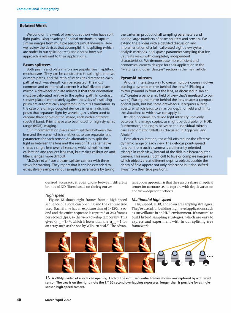
High speedFigure 13 shows eight frames from a high-speed
sequence of a soda can opening and the capture treeused. Each frame has an exposure time of 1/120th sec-ond and the entire sequence is captured at 240 framesper second (fps), so the views overlap temporally. Thisgives , which is lower than the foran array such as the one by Wilburn et al.14 The advan-
tage of our approach is that the sensors share an opticalcenter for accurate scene capture with depth variationand view-dependent effects.
Multimodal high speedHigh speed, HDR, and so on are sampling strategies.
They’re useful for building high-level applications suchas surveillance in an HDR environment. It’s natural tobuild hybrid sampling strategies, which are easy toexpress and experiment with in our splitting treeframework.
qtree
= 1qtree
= 1 4/
Computational Photography
40 March/April 2007
13 A 240-fps video of a soda can opening. Each of the eight sequential frames shown was captured by a differentsensor. The tree is on the right; note the 1/120-second overlapping exposures, longer than is possible for a single-sensor, high-speed camera.
Related Work
We build on the work of previous authors who have splitlight paths using a variety of optical methods to capturesimilar images from multiple sensors simultaneously. Herewe review the devices that accomplish this splitting (whichare nodes in our splitting tree) and discuss how ourapproach is relevant to their applications.
Beam splittersBoth prisms and plate mirrors are popular beam-splitting
mechanisms. They can be constructed to split light into twoor more paths, and the ratio of intensities directed to eachpath at each wavelength can be adjusted. The mostcommon and economical element is a half-silvered platemirror. A drawback of plate mirrors is that their orientationmust be calibrated relative to the optical path. In contrast,sensors placed immediately against the sides of a splittingprism are automatically registered up to a 2D translation. Inthe case of 3-charge-coupled device cameras, a dichroicprism that separates light by wavelength is often used tocapture three copies of the image, each with a differentspectral band. Prisms have also been used for high-dynamicrange (HDR) imaging.1
Our implementation places beam splitters between thelens and the scene, which enables us to use separate lensparameters for each sensor. An alternative is to split thelight in between the lens and the sensor.2 This alternativeshares a single lens over all sensors, which simplifies lenscalibration and reduces lens cost, but makes calibration andfilter changes more difficult.
McGuire et al.3 use a beam-splitter camera with threeviews for matting. They report that it can be extended toexhaustively sample various sampling parameters by taking
the cartesian product of all sampling parameters andadding large numbers of beam splitters and sensors. Weextend these ideas with a detailed discussion andimplementation of a full, calibrated eight-view system,analysis methods, and sparse parameter sampling that letsus create views with completely independentcharacteristics. We demonstrate more efficient andeconomical camera designs for their application in the“Matting and other designs” section in the main article.
Pyramid mirrorsAnother interesting way to create multiple copies involves
placing a pyramid mirror behind the lens.4,5 (Placing amirror pyramid in front of the lens, as discussed in Tan etal.,6 creates a panoramic field of view that’s unrelated to ourwork.) Placing the mirror behind the lens creates a compactoptical path, but has some drawbacks. It requires a largeaperture, which leads to a narrow depth of field and limitsthe situations to which we can apply it.
It’s also nontrivial to divide light intensity unevenlybetween the image copies, as might be desirable for HDR.Furthermore, the edges between the individual mirrorscause radiometric falloffs as discussed in Aggarwal andAhuja.4
Even after calibration, these fall-offs reduce the effectivedynamic range of each view. The defocus point-spreadfunction from such a camera is a differently orientedtriangle in each view, instead of the disk in a beam-splittercamera. This makes it difficult to fuse or compare images inwhich objects are at different depths; objects outside thedepth of field appear not only defocused but also shiftedaway from their true positions.

IEEE Computer Graphics and Applications 41
14 Frames of high-speed video with visible and infrared channels. Note the infrared-only illumination on the subject’s right and at the LED on the remote control.
AlternativesFor flat scenes and scenes far (more than10 m) from the
camera, parallax and view-dependent effects may beignored. In that case the calibration problem is comparativelyeasy, because the sensors’ optical centers needn’t be aligned.Dense arrays of side-by-side sensors (such as in Wilburn etal.7) have captured multiple approximately monocular viewsfor such cases. Arrays capture much more light than asplitting tree. However, a tree can capture both nearby anddeep scenes, and can share filters and other optical elementsover multiple sensors.
We can use a mosaic of filtered CCD pixels to samplemultiple parameters in a single image. The Bayer mosaictiles per-pixel bandpass filters, sampling three wavelengthswith a single monochrome sensor. Recently, some filtermosaics have been proposed for sampling other parameterswith high precision.8,9 This approach can be implementedcompactly and requires no calibration (once manufac-tured), making it ideal for many applications. The drawbackis that it trades spatial resolution for resolution along otherimaging dimensions. Such a system also makes it difficult toexperiment with aperture and timing effects, which weexplored in this article.
Previous commercial optical design systems like Synopsys,Ados, and Zemax emphasize the tracing of rays throughlenses. To the best of our knowledge, none significantlyaddress the issues of sampling the plenoptic functionthrough splitting and spectral response that we discuss here.
References1. E. Ikeda, Image Data Processing Apparatus for Processing Com-
bined Image Signals in Order to Extend Dynamic Range, USpatent 5801773, Sept. 1998.
2. S.K. Nayar, M. Watanabe, and M. Noguchi, “Real-Time FocusRange Sensor,” IEEE Trans. Pattern Analysis and Machine Intelli-gence, vol. 18, no. 12, 1996, pp. 1186- 1198.
3. M. McGuire et al., “Defocus Matting,” ACM Trans. Graphics, vol.24, 2005, pp. 567–576.
4. M. Aggarwal and N. Ahuja, “Split Aperture Imaging for HighDynamic Range,” Int’l J. Computer Vision, vol. 58, no. 1, 2004,pp. 7-17.
5. R.P. Harvey, Optical Beam Splitter and Electronic High-Speed Camera Incorporating Such a Beam Splitter, US patentUS5734507, 1998.
6. K.-H. Tan, H. Hua, and N. Ahuja, “Multiview Mirror Pyramid Cam-eras,” IEEE Trans. Pattern Analysis and Machine Intelligence, vol.26, no. 7, 2004, pp. 941-946.
7. B. Wilburn et al, “High-Speed Video Using a Dense CameraArray,” Proc. Computer Vision and Pattern Recognition, IEEE CSPress, 2004.
8. T. Mitsunaga and S. Nayar, “High Dynamic Range Imaging: Spa-tially Varying Pixel Exposures,” Proc. Computer Vision and PatternRecognition, IEEE CS Press, vol. 1, 2000, pp. 472-479.
9. S. Nayar and S. Narasimhan, “Assorted Pixels: MultisampledImaging with Structural Models,” Proc. European Conf. ComputerVision, 2002, p. 636.
Frame # Color IR luminance Fused result
166
209
286
351
We use the configuration from Figure 4designed by the optimizer to capture hybridhigh-speed visible/infrared video. A hot-mirrordirects infrared down the right subtree and vis-ible light down the left subtree. Each subtreehas four cameras with temporal phase offsets,so the entire system yields 120 fps video withfour spectral samples. Figure 14 shows framesfrom a sequence in which a person catches atumbling infrared remote control and thentransmits it at the camera. Because the config-uration captures four spectral samples at 120fps, the high-frequency infrared pattern trans-mitted by the remote is accurately recorded, asis the fast tumbling motion at the sequence’sbeginning.
Conclusions and future workWe presented a framework useful for manu-
al camera design and an algorithm for automat-ic design. We also implemented a configurablesystem that samples multiple parameters perframe and demonstrated its utility. Using ourframework and this system, high-precisionimaging applications become easier to developand produce results of comparable or betterquality than alternative solutions. Manualdesigns are easily understood but rely excessive-ly on the notion of ideal components. Automat-

ically designed trees contain surprising and complex ele-ment choices. These microbalance the true responsecurves of components and are frequently more efficient.
For future work, we’re investigating multispectralHDR for surveillance, alternative multifocus approach-es for matting, and multispectral high-speed video formaterial testing in the context of splitting trees. Anoth-er area of future work is addressing the limitations ofthe current automatic design approach to find more effi-cient and general designs. For example, element costshould be a function of tree depth, since filters closer tothe root must be larger to fill the field of view. We believethat genetic algorithms are likely to produce better out-put than our optimizer because they’re naturally suitedto a tree combination.
The optical elements form a filter system that terminatesat digital sensors. In an application, this is always followedby a digital filter system. The next step is to simultaneous-ly design both the optical and software filter systems. ■
References1. P.E. Debevec and J. Malik, “Recovering High Dynamic
Range Radiance Maps from Photographs,” Proc. Siggraph,ACM Press, 1997, pp. 369-378.
2. T. Mitsunaga and S. Nayar, “High Dynamic Range Imag-ing: Spatially Varying Pixel Exposures,” Proc. IEEE CS Conf.Computer Vision and Pattern Recognition (CVPR), vol. 1,IEEE CS Press, 2000, pp. 472–479.
3. M. Aggarwal and N. Ahuja, “Split Aperture Imaging forHigh Dynamic Range,” Int’l J. Computer Vision, vol. 58, no.1, 2004, pp. 7-17.
4. S.K. Nayar, M. Watanabe, and M. Noguchi, “Real-TimeFocus Range Sensor,” IEEE Trans. Pattern Analysis andMachine Intelligence, vol. 18, no. 12, 1996, pp. 1186- 1198.
5. S. Chaudhuri and A. Rajagopalan, Depth from Defocus: AReal Aperture Imaging Approach, Springer Verlag, 1998.
6. Y. Xiong and S. Shafer, “Depth from Focusing and Defocus-ing,” Proc. Computer Vision and Pattern Recognition, IEEECS Press, 1993, pp. 68-73.
7. M. Subbarao, “Parallel Depth Recovery by Changing Cam-era Parameters.” Proc. 6th Int’l Conf. Computer Vision(ICCV), IEEE CS Press, 1998, pp. 149-155.
8. M. McGuire et al., “Defocus Matting,” ACM Trans. Graph-ics, vol. 24, 2005, pp. 567-576.
9. P. Debevec et al., “A Lighting Reproduction Approach toLive-Action Compositing,” ACM Trans. Graphics, vol. 21.no. 3, 2002, pp. 547-556.
Morgan McGuire is an assistantprofessor of computer science atWilliams College. His research inter-ests include multisensor imaging,video as an input device, real-timerendering, real-time physics, and theengineering of rule systems for puzzlesand games. McGuire received his BS
and MEng in electrical engineering and computer sciencefrom the Massachusetts Institute of Technology (MIT) andhis MS and PhD in computer science from Brown Univer-sity. Contact him at [email protected].
Wojciech Matusik is a research sci-entist at Mitsubishi Electric ResearchLaboratories (MERL). His primaryinterests are computer graphics, data-driven modeling, computational pho-tography, and new display technolo-gies. Matusik received the followingdegrees in electrical engineering and
computer science: a BS in from the University of Califor-nia at Berkeley, an MS from MIT, and a PhD from MIT.Contact him at [email protected].
Hanspeter Pfister is a seniorresearch scientist at MERL. Hisresearch is at the intersection of com-puter graphics, visualization andcomputer vision. Pfister has a PhD incomputer science from the State Uni-versity of New York at Stony Brook. Heis chair of the IEEE Visualization and
Graphics Technical Committee (VGTC). Contact him [email protected].
Billy Chen is a software develop-ment engineer for the Virtual Earthteam at Microsoft. His research inter-ests include image-based modeling,computational photography, and projector-camera systems. Chenreceived a BS in electrical engineeringand computer science from the Univer-
sity of California, Berkeley, and an MS and PhD in com-puter science from Stanford University. Contact him at [email protected].
John F. Hughes is an associate pro-fessor of computer science at BrownUniversity. His interests include geo-metric modeling, expressive render-ing, sketch-based interfaces, the inter-face between computer vision andcomputer graphics, and machinelearning. Hughes received a BA in
mathematics from Princeton University and an MA andPhD in mathematics from the University of California,Berkeley. Contact him at [email protected].
Shree K. Nayar is the T.C. ChangChaired Professor in the Departmentof Computer Science at Columbia Uni-versity. He’s also the codirector of theColumbia Vision and Graphics Centerand heads the Computer Vision Labo-ratory. His research is focused on threebroad areas—the creation of novel
vision sensors, the design of physics-based models forvision, and the development of algorithms for sceneinterpretation. Nayar received his PhD in electrical andcomputer engineering from the Robotics Institute atCarnegie Mellon University. Contact him at [email protected].
Computational Photography
42 March/April 2007