optical properties of coupled metallic nanorods for field...
TRANSCRIPT
Optical properties of coupled metallic nanorods for field-enhanced spectroscopy
J. Aizpurua,1,2,* Garnett W. Bryant,1,† Lee J. Richter,1 and F. J. García de Abajo2,3
1National Institute of Standards and Technology, 100 Bureau Drive, Gaithersburg, Maryland 20899, USA2Donostia International Physics Center, Paseo Manuel de Lardizabal 4, 20018 Donostia, Spain
3Centro Mixto CSIC-UPV/EHU, Apartado Postal 1072, 20080 San Sebastian, Spain
Brian K. Kelley and T. MalloukDepartment of Chemistry, 152 Davey Laboratory, Pennsylvania State University, University Park, Pennsylvania 16802, USA
�Received 30 December 2004; published 28 June 2005�
The optical properties of coupled metallic nanorods are studied to investigate the use of coupled plasmonicstructures in field-enhanced spectroscopies. Light scattering by coupled nanorods is calculated with the bound-ary element method, including retardation. The modes of coupled nanorod systems are calculated by theboundary charge method and discussed in terms of their symmetry. Similar scattering behavior for isolatednanorods and pairs of nanorods can mask the very different local responses that produce near-field enhance-ment. The response of isolated rods redshifts with increasing rod length because intrarod restoring forces arereduced. The near- and far-field responses increase monotonically with increasing rod length �increasingpolarization along the rod�. For coupled nanorods, coupling localizes charge at the gap between the rod endsand splits degenerate modes. The localized charge depolarizes the intrarod response and provides an additionalredshift. Moreover, the near-field enhancement in the gap between the nanorods is dramatically increased bycoupling-induced charge localization at the gap. For short nanorods, the near-field response in coupled systemsis determined by the geometry of the rod ends that define the gap. For longer nanorods, the response in coupledsystems is determined by the rod length. Changing the dimensions and geometry of the nanorods to modify theinterrod coupling has a major effect on the local-field enhancement. The effects of the environment and theactual metallic material do not have as big an influence on the field enhancement.
DOI: 10.1103/PhysRevB.71.235420 PACS number�s�: 78.67.�n, 61.46.�w, 73.20.Mf
I. INTRODUCTION
The optical properties of molecules can be influenced dra-matically by coupling to the plasmon resonances of nearbymetallic structures. This coupling can lead to harmful effects,such as the quenching of fluorescent molecules by metallicfilms,1 or to useful effects, such as surface-enhanced Ramanscattering2,3 �SERS� and tip-enhanced scattering.4 The dem-onstration of single-molecule sensitivity5–7 via SERS hasprompted a renewed interest in the electromagnetic responseof nanostructured metallic systems. A consensus is emergingthat the extreme enhancement of the optical field required toobserve single-molecule Raman scattering occurs in the gapsbetween metal nanoparticles.5,8–10 This revived, strong inter-est in metallic nanostructures has stimulated the synthesis ofmore complex structures11–18 to enhance local fields on thenanoscale.19 A number of experimental efforts have recentlycharacterized the far-field scattering of coupled metal nano-particles, either pairs or two-dimensional �2D� arrays.20,21
However, in virtually all of these studies, the gap betweenthe particles was limited to dimensions �20 nm because ofconstraints in the lithographic fabrication.
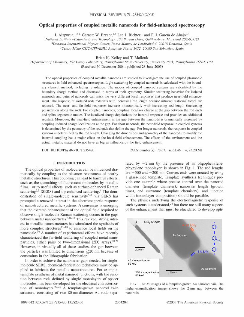
In order to achieve the nanometer gaps needed for single-molecule SERS, chemical-fabrication techniques must be ap-plied to fabricate the metallic nanostructures. For example,template synthesis of metal nanorod junctions, with the junc-tion between rods defined by single monolayers of spacermolecules, has been developed for the electrical characteriza-tion of monolayers.22,23 A template-grown nanorod twinstructure, consisting of two 80 nm diameter Au rods sepa-
rated by �2 nm by the presence of an oligophenylene-ethynylene monolayer, is shown in Fig. 1. The rod lengthsare �500 and �200 nm. Convex ends were created by usinga glass-lined template. Template synthesis techniques pro-vide one example where precise control over the nanoroddiameter �template diameter�, nanowire length �growthtime�, end curvature �template chemistry�, and junctionwidth �monolayer composition� should be possible.
The physics underlying the electromagnetic response ofsuch systems is understood,24 but there are still many aspectsof the enhancement that must be elucidated to develop opti-
FIG. 1. SEM images of a template-grown Au nanorod pair. Thehigher-magnification image shows the 2 nm gap between thenanorods.
PHYSICAL REVIEW B 71, 235420 �2005�
1098-0121/2005/71�23�/235420�13�/$23.00 ©2005 The American Physical Society235420-1

mal nanostructures for field-enhanced spectroscopy. To un-derstand the optical response of such strongly coupled me-tallic nanorods, here we present calculations of the opticalresponse of isolated and coupled nanorod structures. Thepioneering studies of the optical response of a sphere byMie25 and more recent studies dealing with variousnanoparticles,26–29 complex nanoshells,30 nanorings,31 andaggregates of particles,20,21,32–35 even including the use ofdensity-functional techniques to obtain the response of thesystem,36 show that classical electromagnetic theory gives areasonable description of the optical response of metallicnanostructures.
We have performed detailed calculations of the classicalelectromagnetic response of coupled Au nanorods to betterdefine the rod diameter, rod length, and gap distance neededfor optimal coupled structures. Both the far- and near-fieldresponses are determined. To date, other authors have re-ported the optical response,37 plasmon relaxationdynamics,38 and coupling with metallic surfaces39 for iso-lated nanorods. Here we present results for isolated nanorodsto better understand the response of coupled nanorods. Sucha comparison is important. Although isolated and couplednanorods have similar optical response, there are importantdifferences in their local response and polarization that gov-ern their optical properties. In addition, we determine themodes underlying the optical response of isolated andcoupled nanorods and use these modes to characterize theoptical response at different wavelengths.40,41 Other materi-als, such as silver and aluminum, are also considered to de-termine the effect of material response.
II. CALCULATION METHOD
The optical response of nanorods is calculated by meansof the boundary element method in a full electromagneticcalculation,42 including retardation. Retardation must be in-cluded because we consider structures with lengths that canbe larger than a wavelength. Maxwell’s equations for inho-mogeneous media with sharp boundaries are solved in termsof charges and currents distributed on the surfaces and inter-faces. Boundary conditions are imposed via surface integralsalong the boundaries between different media. Each region ischaracterized by a local dielectric function. The externalfields interact self-consistently with the induced boundarycharges and currents, which are determined by discretizingthe surface integrals and solving the appropriate matrix equa-tions. In this approach, the scattered field due to an incidentexternal field is calculated directly. We calculate, in this way,both the near and far fields for a given structure.
To illustrate the optical response of coupled nanorods, wealso calculate the modes of isolated and coupled metallicnanorods. We determine the modes in the electrostatic limitby solving the Laplace equation with the use of the boundarycharge method.43 Full calculations �done with retardation�and electrostatic calculations �done without retardation� pre-dict the same general trends and dependences on geometry,although a direct quantitative comparison between the twoapproaches can be complicated by the large redshifts becauseof retardation �see, for example, the comparison in Ref. 42�.
In the full calculation, both surface-charge and surface-current densities must be determined to characterize a mode.In the nonretarded limit, only a surface-charge density isneeded to characterize a mode. Here, we do the mode analy-sis in the simpler electrostatic limit because this limit gives areasonable, qualitative description that provides a good,more intuitive understanding of the full optical response.
In the electrostatic limit, when the materials inside andoutside the nanosystem are homogeneous, the eigenvalues �iare calculated from the eigenequation obtained by imposingthe boundary conditions43
�i�i�s� = − �S
ds�ns · �s − s��
�s − s��3�i�s�� , �1�
where �i�s�� is the surface-charge density, s and s� are spacevectors for points on the surfaces S of the rods, the integral isa surface integral over points s� on S, and ns is the normalvector to the surface at point s. We obtain a series of eigen-values that depend on the geometry of the nanostructure. Theparticular energy �� or wavelength � of the mode is ob-tained by means of the functional relationship that the eigen-value �i and the dielectric functions fulfill
�i = 2�2��� + 1���2��� − 1���
. �2�
The dielectric functions 1 and 2 are the �-dependent di-electric functions inside and outside the structure �as definedby ns�. For dielectric functions, we use tabulated data in theliterature �see Ref. 44�.
III. LIGHT SCATTERING BY ISOLATED NANORODS
First, we discuss the response of isolated nanorods so thatwe can better understand the response of coupled systems.We consider single cylindrical gold nanorods with a radiusR=40 nm and hemispherical, rounded ends, similar to therods shown in Fig. 1. The rods are surrounded by vacuum�2=1�. We determine both the far- and near-field responsesfor a plane-wave incident perpendicular to the nanorod withthe light polarized parallel to the rod axis. The far-field ob-servation point is in the plane defined by the rod axis andpropagation direction �see the schematic in Fig. 2�a��. Thedependence of the far-field intensity on the incident-fieldwavelength � for different lengths L of the nanorods isshown in Fig. 2. Here, L is defined as the length of thecylindrical section of the nanorod. For a sphere �nanorodwith L=0�, a peak in the far-field response is seen at thewavelength sphere�510 nm. sphere is independent of sphereradius for small spheres and redshifts slightly, because ofretardation, for large spheres.45 For small L, a single peak isseen at the wavelength 1. As L increases, this peak redshiftsto the near infrared. The L dependence of 1 is shown in Fig.3. A similar linear L-dependence is obtained in nonretardedcalculations for nanorods.37 Our results for nanorods, whichinclude the effects of retardation, are redshifted from thenonretarded limit. This long-wavelength peak results fromdipolar longitudinal charge oscillation37 along the rod axis,which is consistent with the mode charge distribution shown
AIZPURUA et al. PHYSICAL REVIEW B 71, 235420 �2005�
235420-2
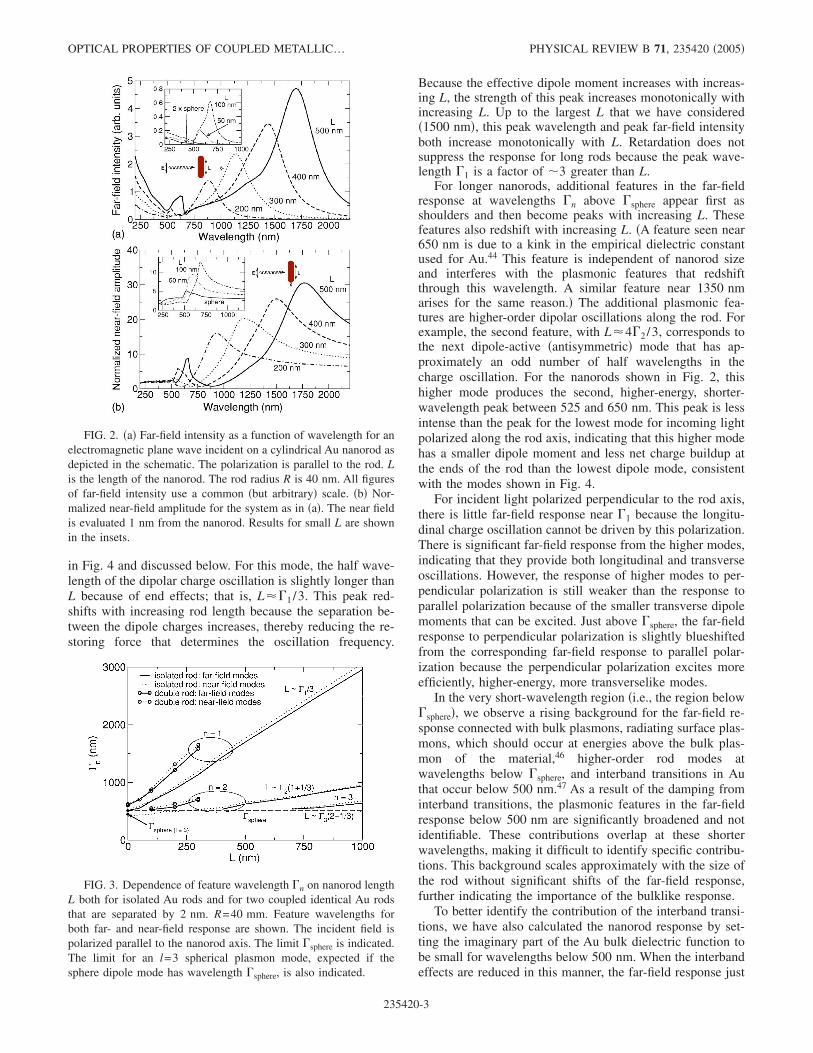
in Fig. 4 and discussed below. For this mode, the half wave-length of the dipolar charge oscillation is slightly longer thanL because of end effects; that is, L�1 /3. This peak red-shifts with increasing rod length because the separation be-tween the dipole charges increases, thereby reducing the re-storing force that determines the oscillation frequency.
Because the effective dipole moment increases with increas-ing L, the strength of this peak increases monotonically withincreasing L. Up to the largest L that we have considered�1500 nm�, this peak wavelength and peak far-field intensityboth increase monotonically with L. Retardation does notsuppress the response for long rods because the peak wave-length 1 is a factor of �3 greater than L.
For longer nanorods, additional features in the far-fieldresponse at wavelengths n above sphere appear first asshoulders and then become peaks with increasing L. Thesefeatures also redshift with increasing L. �A feature seen near650 nm is due to a kink in the empirical dielectric constantused for Au.44 This feature is independent of nanorod sizeand interferes with the plasmonic features that redshiftthrough this wavelength. A similar feature near 1350 nmarises for the same reason.� The additional plasmonic fea-tures are higher-order dipolar oscillations along the rod. Forexample, the second feature, with L�42 /3, corresponds tothe next dipole-active �antisymmetric� mode that has ap-proximately an odd number of half wavelengths in thecharge oscillation. For the nanorods shown in Fig. 2, thishigher mode produces the second, higher-energy, shorter-wavelength peak between 525 and 650 nm. This peak is lessintense than the peak for the lowest mode for incoming lightpolarized along the rod axis, indicating that this higher modehas a smaller dipole moment and less net charge buildup atthe ends of the rod than the lowest dipole mode, consistentwith the modes shown in Fig. 4.
For incident light polarized perpendicular to the rod axis,there is little far-field response near 1 because the longitu-dinal charge oscillation cannot be driven by this polarization.There is significant far-field response from the higher modes,indicating that they provide both longitudinal and transverseoscillations. However, the response of higher modes to per-pendicular polarization is still weaker than the response toparallel polarization because of the smaller transverse dipolemoments that can be excited. Just above sphere, the far-fieldresponse to perpendicular polarization is slightly blueshiftedfrom the corresponding far-field response to parallel polar-ization because the perpendicular polarization excites moreefficiently, higher-energy, more transverselike modes.
In the very short-wavelength region �i.e., the region belowsphere�, we observe a rising background for the far-field re-sponse connected with bulk plasmons, radiating surface plas-mons, which should occur at energies above the bulk plas-mon of the material,46 higher-order rod modes atwavelengths below sphere, and interband transitions in Authat occur below 500 nm.47 As a result of the damping frominterband transitions, the plasmonic features in the far-fieldresponse below 500 nm are significantly broadened and notidentifiable. These contributions overlap at these shorterwavelengths, making it difficult to identify specific contribu-tions. This background scales approximately with the size ofthe rod without significant shifts of the far-field response,further indicating the importance of the bulklike response.
To better identify the contribution of the interband transi-tions, we have also calculated the nanorod response by set-ting the imaginary part of the Au bulk dielectric function tobe small for wavelengths below 500 nm. When the interbandeffects are reduced in this manner, the far-field response just
FIG. 2. �a� Far-field intensity as a function of wavelength for anelectromagnetic plane wave incident on a cylindrical Au nanorod asdepicted in the schematic. The polarization is parallel to the rod. Lis the length of the nanorod. The rod radius R is 40 nm. All figuresof far-field intensity use a common �but arbitrary� scale. �b� Nor-malized near-field amplitude for the system as in �a�. The near fieldis evaluated 1 nm from the nanorod. Results for small L are shownin the insets.
FIG. 3. Dependence of feature wavelength n on nanorod lengthL both for isolated Au rods and for two coupled identical Au rodsthat are separated by 2 nm. R=40 mm. Feature wavelengths forboth far- and near-field response are shown. The incident field ispolarized parallel to the nanorod axis. The limit sphere is indicated.The limit for an l=3 spherical plasmon mode, expected if thesphere dipole mode has wavelength sphere, is also indicated.
OPTICAL PROPERTIES OF COUPLED METALLIC… PHYSICAL REVIEW B 71, 235420 �2005�
235420-3

below 500 nm is significantly weaker, while the responsenear 200 nm from radiating plasmons remains sizable. Fea-tures due to rod modes below 500 nm become more apparentwhen the interband damping is reduced.
The near-field amplitude on the rod axis, 1 nm outside theend of the nanorod and normalized to the incident field atthis point, is shown in Fig. 2�b�. The normalized near fieldshows features similar to those in the far field, with n andthe field enhancement increasing monotonically with in-creasing L. Near-field enhancements of 10–70 �for L=1500 nm� are seen for isolated rods. However, the near-field features are slightly redshifted from the correspondingfar-field features and have different relative weights. The far-field response also has sharper long wavelength peaks.
The near-field response below sphere is weak, indicatingthat the bulklike response below sphere contributes weakly tothe near field. Because the interband damping has less effecton the near-field response, broad plasmonic �length-dependent� features are discernible in the weak near-fieldresponse below sphere. As shown in Fig. 3, the feature for 2can be followed back to the sphere limit �L=0�. 1 clearlyevolves from the lowest dipole-active �angular momentuml=1� spherical plasmon mode. 2 evolves from a higher-order spherical plasmon, presumably the next dipole-active�l=3� spherical plasmon. �Far-field features cannot be clearly
identified below sphere, therefore they are not shown in thisregion. Similarly, 3 cannot be followed clearly down to theL=0 limit.�
To further understand the excitations produced in the na-norods, we calculate the surface plasmon modes in thesestructures by means of the boundary charge method in theelectrostatic limit. The features n in the far- and near-fieldresponses should correlate with the dipole-active modes. Thesurface charge distributions ��s� for the lowest modes of anisolated gold nanorod are shown in Fig. 4 for azimuthal num-ber m=0. In the electrostatic limit, the wavelengths � of themodes are obtained from the � that solve Eq. �2� with use ofthe eigenvalues of Eq. �1� and the tabulated data for gold.44
The lowest mode is a zero-order mode, which does not haveany oscillation along the rod axis. This mode has finitecharge, is connected with infinitely long wavelength oscilla-tions, and cannot be excited by an external electromagneticwave. The first mode with physical meaning is a dipolarmode, with a nodal ring around the rod axis at the center ofthe rod, which piles up positive and negative charge at op-posite ends of the nanorod. This mode responds to a fieldpolarized along the axis and drives the response at longwavelength �the n=1 peak�. The low-order m=0 modes canbe identified by the number of nodal rings around the rodaxis. Even-order modes have an even number of nodal rings
FIG. 4. Cross sections of the surface-modessurface-charge density in an isolated gold nano-rod. L=200 nm, R=40 nm. These modes havem=0 azimuthal number, so the surface-chargedensity is cylindrically symmetric around the rodaxis. The bulk and surface plasmon wavelengthsin gold are 226 and 392 nm, respectively.
AIZPURUA et al. PHYSICAL REVIEW B 71, 235420 �2005�
235420-4

and no net dipole in their charge distribution. Odd-ordermodes, with an odd number of nodal rings and an odd num-ber of half wavelengths, always have charges of oppositesign at the nanorod ends, giving a net dipole. For both typesof modes, the wavelengths decrease as additional longitudi-nal nodes are added. For higher-order modes, the surface-charge oscillation includes nodes on the rounded ends of therod. These modes have partial transverse character in theoscillation pattern and can be excited by transverse fields.These modes are connected with the features observed justabove sphere and with the weak structure observable belowsphere in the near-field response. They are also present in theresponse to an incident wave with longitudinal polarization,both because these modes have mixed longitudinal and trans-verse character and because end effects can provide a cou-pling of transverselike modes to a longitudinal polarization.
As seen in Fig. 4, the surface charge of each mode has akink where the hemispherical cap begins, such that the localeffective wavelength of the charge oscillation is longer onthe cap than on the cylindrical shaft of the rod. This suggestsa local slowing down of the charge oscillation due to thecharge buildup at the ends.48
IV. LIGHT SCATTERING BY COUPLED NANORODS
To investigate the effects of coupling between nanorods,we consider pairs of nanorods aligned along a common axisas in the experimental setup described in the introduction.We first present the far- and near-field responses for a planewave incident on a pair of gold cylindrical nanorods, each200 nm long and 40 nm in radius. Each end of the nanorodsis rounded with a hemispherical cap. The light is incidentnormal to the axis of the rods with polarization along the rodaxis. The far field is calculated as for the isolated rod,whereas the normalized near field is calculated along the rodaxis between the rods.
Figure 5 shows the change in the far- and near-field re-sponses at the midpoint between the rods when the separa-tion S between rods is varied to modify the coupling. Ingeneral, the same features are seen for isolated and coupledrods. There is a long-wavelength peak because of the lowestdipole-active mode. The position 1 of this peak redshifts by300 nm when the gap S is reduced to 2 nm because of thedepolarization of the intrarod charge oscillations induced bythe coupling. As discussed later �see Figs. 6 and 10�, oppo-site charges are strongly localized to the ends of the two rodsat the gap when the rods are coupled. Strong attraction acrossthe gap competes against the intrarod, restoring forces thatdrive the intrarod charge oscillations and provides this addi-tional redshift.20,21,33 As for the isolated rod, the near-fieldresponse is redshifted slightly from the far-field response forcoupled rods.
Figure 7 summarizes the gap dependence of 1 for thefar-field response, and for the near-field response both in thegap 1 nm from the end of a rod and at the midpoint of thegap. The near-field response is redshifted from the far-fieldresponse at all S. If the gap is small, the near-field responseat any point in the gap along the rod axis is nearly the same,with the near-field response at midgap slightly redshifted
from the response 1 nm from a rod end. For large gaps, thenear-field response at different points along the axis in thegap can be significantly different, with 1 at the midgapsubstantially redshifted from the 1 for the response 1 nmfrom an end. For large gaps, 1 for the far-field response andfor the near-field response 1 nm from the rod end both oscil-late about the appropriate limits for an isolated rod, with theoscillation slowly damping as S increases. This oscillationreflects an oscillation in the sign of the coupling betweenrods because of retardation when the gap is greater than a
FIG. 5. �a� Far-field intensity as a function of wavelength for aplane wave incident on a pair of identical cylindrical Au nanorods,as shown in the schematic. S is the separation distance between thenanorods. L=200 nm, R=40 nm. The polarization is parallel to therod. �b� Normalized near-field amplitude at the midpoint betweentwo nanorods for the same geometry as in �a�.
FIG. 6. Model of the expected surface-charge distribution thatdrives the long-wavelength dipolar response of an isolated rod, oftwo widely spaced, weakly coupled rods, and of two closely spaced,strongly coupled rods.
OPTICAL PROPERTIES OF COUPLED METALLIC… PHYSICAL REVIEW B 71, 235420 �2005�
235420-5

quarter wavelength.21 For large S, the field at midgap issmall. We have not followed the S dependence of 1 at mid-gap beyond this point.
The S dependence of the intensity of the long-wavelength,dipolar far-field response �see Fig. 7� can be understood withthe simple coupled dipole picture illustrated in Fig. 6. If anincident field induces a charge ±Q at the ends of an isolatedrod, then almost the same charges ±Q should be induced atthe ends of two widely spaced, weakly coupled rods. Thedipole moment due to the charge at the two outside ends ofthe coupled rod structure is roughly Q�2L+S� �here thelength of the rod caps is ignored for simplicity�. The dipolemoment due to charge at the gap is −QS. The net dipolemoment is �2QL, twice the dipole moment of an isolated
rod. The intensity of the far-field response of two widelyspaced rods should be four times the response of an isolatedrod. As shown in Fig. 7, the intensity of the far-field responsefor widely spaced rods oscillates �because of the retardationof the coupling� about the expected limit. For closely spacedrods, the strong coupling distorts the intrarod charge distri-bution. Charge induced at the gap by the incident field isstrongly localized by the attraction between charges acrossthe small gap. In reaction, the charge at the outside ends ofthe rods is drawn closer to the gap �see Figs. 6 and, later, 10�,reducing the intrarod charge separation in the stronglycoupled structure. As a result the dipole moment from thecharges at the outside ends is �Q�2L+S� and the total dipolemoment of the strongly coupled structure is less than thedipole moment of two widely spaced rods. This explains thedecrease in far-field response as S is reduced from theweakly coupled regime. The small increase in far-field re-sponse at the smallest S indicates that the induced charge ±Qcan increase when the coupling becomes strong enough.
The near-field enhancement in the gap is drastically in-creased when the gap is reduced to 2 nm. The near-fieldenhancement is a factor of �300 for the smallest gap. Heu-ristically, this is roughly the square of the near-field enhance-ment at the end of an isolated rod. One factor is due to theenhancement at the end of a rod, the second is due to theenhanced local field of the other rod that drives the first rod.For small S, the near-field enhancement is similar at allpoints on the rod axis in the gap. The enhancement decreasesrapidly as S increases because the coupling is weaker. Theenhancement at midgap decreases even faster with increasingS because the midpoint is further from the end of the rod.
For S=20 nm, the near-field enhancement for coupledrods is only a factor of 2 greater than for the isolated rod.Thus very small, nanometer-sized gaps are needed to getsignificant increases in the near field at the midpoint of thegap. In the context of a Raman experiment with the signalproportional to the fourth power of the field,2 the Ramansignal from a molecule in middle of the smallest gap wouldbe enhanced by 1010 relative to the Raman signal of a mol-ecule in free space and by a factor of 105 relative to a mol-ecule at the end of an isolated rod.
Simply by looking at the far-field response, it would bedifficult to distinguish whether a long-wavelength near-infrared peak is due to a coupled pair of nanorods �see Fig.5�a�� or whether the peak is due to a nanorod that is roughlytwice as long �see Fig. 2�a��. The near-field response distin-guishes between these two possibilities. The near-field en-hancement at the end of the nanorod is �30 for a 500 nmlong nanorod, whereas the pair of nanorods shows an en-hancement of the near-field in the gap of �300. Even thoughthe energy �wavelength� of far- and near-field features can besimilar, the near fields induced at the nanorods are muchstronger in a coupled system. These differences are importantfor field-enhanced spectroscopies.
The feature just above sphere, which is due to higher-order longitudinal and transverse modes, is also redshifted bythe depolarization induced by the coupling and charge local-ization at the gap �see Fig. 5�. However, the redshift issmaller than for the long-wavelength peak. The long-wavelength peak is more sensitive to S. Charge piles up at
FIG. 7. Dependence of the far-field and near-field response of apair of coupled identical Au nanorods on the interrod gap S for aplane wave incident with polarization parallel to the rods. L=200 nm, R=40 nm. The peak wavelength 1 for the dipolar re-sponse, the far-field intensity at 1, and the normalized near-fieldamplitude at 1, both at midgap and in the gap 1 nm from the endof a rod, are shown. The corresponding results for an isolated rodare shown.
AIZPURUA et al. PHYSICAL REVIEW B 71, 235420 �2005�
235420-6

the gap mainly in a dipolar pattern for the long-wavelengthresponse �see the following discussion on modes�, which canstrongly reduce the intrarod restoring forces and redshift theresponse. However, the feature near sphere is connected withmore transverselike modes with oscillations of the charge atthe round ends of the rods and with higher-order longitudinalmodes. Both types of modes are less effective at supportingcharge localization at the gap and reducing the intrarod re-storing forces. Still, the feature just above sphere becomesmore apparent and sharper in the coupled nanorods for L=200 nm, even though it is not clearly shifted away fromsphere for the isolated rod with the same length, because ofthe redshift due to the coupling. Again, this feature in thefar-field response is weakly enhanced by the coupling. Theenhancement of this feature is much greater for the near-fieldresponse of the coupled nanorods.
The response below sphere due to the radiating plasmonsand the bulklike response is essentially unchanged by thecoupling. The near-field response below sphere is very weak.The far-field response below sphere is independent of the gapand roughly a factor of 4 greater than for an isolated rod, aswould be expected if the radiated field at short wavelength isproportional to the total volume �or length� of the structure.
The dependence of the far- and near-field responses oftwo coupled, identical nanorods on rod length L is shown inFig. 8. The L-dependence of the feature positions n isshown in Fig. 3. As for the isolated rods, the n increasemonotonically with increasing L for the coupled rods. Fea-
tures become sharper as L increases because the modes aremore widely separated. The long-wavelength far-field inten-sity increases monotonically with increasing L, whereas thefar-field intensity below sphere scales roughly as the volumeof the coupled rods. For small L, the near-field enhancementat the long-wavelength peak actually decreases slightly forincreasing L �compare Figs. 2 and 8�. For L�150 nm, thepeak near-field enhancement increases monotonically withincreasing L. This suggests that there are two regimes ofinterest. For small L, the field enhancement is not sensitive tothe rod length, rather it is determined by rod termination �thelightning rod effect�.49 For longer rods, the field enhance-ment is determined primarily by the strength of the dipolethat can be excited along each nanorod and increases mono-tonically with increasing L.
Similar control of the far- and near-field responses can beachieved while keeping one nanorod fixed and varying thelength of the second nanorod. The dependence of the re-sponse on rod length in asymmetric, coupled rods is shownin Fig. 9. One rod is fixed at a length of 200 nm, while thelength of the second rod is varied. The position of the near-infrared peak can be tuned by varying the rod length, red-shifting because of the reduction in intrarod restoring forcethat increases with rod length. The strength of the near-infrared response also increases as the rod length increases.The middle peak is less sensitive to rod length. The far-field
FIG. 8. �a� Far-field intensity as a function of wavelength for aplane wave incident on a pair of identical cylindrical Au nanorodswith S=2 nm and the indicated lengths L. R=40 nm. The polariza-tion is parallel to the rod. �b� Normalized near-field amplitude at themidpoint between two nanorods for the same geometry as in �a�.The insets show the results for small L and for two coupled spheres.
FIG. 9. �a� Far-field intensity as a function of wavelength for aplane wave incident on an asymmetric pair of cylindrical Au nano-rods with S=2. The length of one nanorod is 200 nm. L for thesecond nanorod is varied as indicated. R=40 nm. The polarizationis parallel to the rod. �b� Normalized near-field amplitude at themidpoint between two nanorods for the same geometry as in �a�.
OPTICAL PROPERTIES OF COUPLED METALLIC… PHYSICAL REVIEW B 71, 235420 �2005�
235420-7

response at the shortest wavelengths scales with rod length,as expected for this bulklike response. For the far-field re-sponse, there does not appear to be any special length foroptimal response. For the nearfield, the response at mid-wavelengths is optimal for rods of similar length.
The monotonic increase in n for coupled, identical nano-rods with increasing L is shown in Fig. 3. When the n forthe coupled nanorods are plotted versus the total length ofthe coupled nanorods, Ltot=2L rather than L �not shown inFig. 3�, then the two regimes of behavior can again be seen.For small Ltot, the n for the coupled nanorods are still red-shifted from the n for an isolated nanorod with L=Ltot. Thisindicates that the additional redshift due to the depolarizationof the intrarod oscillations by the coupling between chargeson the opposite sides of the gap is larger than the additionalredshift in an isolated rod due to the reduction of the intrarodrestoring force. For larger Ltot, the n for the coupled nano-rods is blueshifted from n for an isolated nanorod with L=Ltot. Reduction of the intrarod restoring force because ofincreasing rod length determines the redshift for isolatedrods. For coupled nanorods with large Ltot, the reduction ofthe intrarod restoring force is again the dominant effect, butthe interrod coupling makes this reduction less significant fora coupled nanorod pair with total length Ltot than for anisolated nanorod with the same length. As discussed previ-ously �see Fig. 6�, the charges at the outside ends of the twocoupled rods are closer together than they would be if therewere no coupling, that is, in an isolated rod with L=Ltot. Asa result, the reduction of the restoring forces due to increas-ing length is less in the coupled structure than in the isolatedstructure with the same total length.
The far-field response provides a direct measure of thedipole moment induced by the incident field. A comparisonof the far-field response for isolated and coupled rods withthe same total length �see Figs. 2, 8, and 9� again reveals thetwo regimes of behavior for fixed S. For large Ltot, the far-field response of an isolated rod is larger than the far-fieldresponse for the coupled structure with the same Ltot. Asmentioned before, because of the coupling, the separationbetween the outside charges in a coupled structure is less, forlarge Ltot, than in a isolated rod with the same total length.This provides a smaller dipole moment. For small Ltot, thefar-field response of an isolated rod is smaller than the far-field response for the coupled structure with the same Ltot.This indicates that more charge is polarized in short coupledstructures than in the isolated rods with the same total length.As mentioned previously, increased charge polarization alsoexplains the S dependence of the far-field intensity in thelimit of very strong coupling �Fig. 7�.
Isolated and coupled rods exhibit a similar response. Theprimary differences are the splitting of degenerate modes, thecoupling-induced intrarod charge distortion and reduction ofintrarod restoring forces, and the resulting redshifts of fea-tures and drastic enhancements of the near field in thecoupled structures. These differences occur because themodes are significantly modified by the coupling. As shownin Fig. 4, the modes for an isolated rod are either dipoleactive with surface-charge distributions that are antisymmet-ric about the rod center with an odd number of nodes in thecharge distribution or symmetric �dipole-inactive� with an
even number of nodes. This symmetry is broken when tworods are coupled together. The modes of a pair of couplednanorods are shown in Fig. 10 for m=0. For two coupledidentical rods, the surface-charge distribution of a mode iseither symmetric or antisymmetric about the midpoint of thegap. Moreover, the modes of the coupled system should beformed from symmetric and antisymmetric combinations ofthe modes of the isolated rod. Figure 10 shows that this is thecase.
Three different types of modes can be distinguished. First,a branch of antisymmetric, coupled modes is associated withstrong, attractive coupling of the localized charge at the gapbetween the nanorods �modes 0a,1a,2a,… in Fig. 10�. Thesemodes pile up a very high surface-charge density of oppositesign on the adjacent nanorods surfaces at the gap, forming astrong dipolarlike distribution at the gap, as happens for twocoupled spheres.16 As for mode 0 of an isolated rod, mode 0ais unphysical �unless charge tunneling between the rods ispossible� because this mode has a finite charge on each rod.All higher modes are charge neutral on each rod. Because ofthe strong attractive interaction between the opposite chargesacross the gap, there is significant reduction of intrarod re-storing forces and redshift of these modes. These modes canbe characterized by the number of nodes per rod. As shownon the left-hand side of Fig. 10, those modes with an oddnumber of nodes per rod are, effectively, symmetric combi-nations of the antisymmetric modes of the isolated rod. How-ever, these modes are not strict symmetric combinations ofthe corresponding rod modes. There is a large distortion ofthe intrarod mode and charge pileup at the gap. Moreover,the nodes in the charge distribution shift toward the gap be-cause of the charge pileup. These modifications of the chargedistribution break the intrarod symmetry. Those modes withan even number of nodes per rod are antisymmetric combi-nations of the symmetric modes of the isolated rod. Thesemodes also exhibit the charge pileup at the gap, and theshifting of the nodes are indicative of the broken intrarodsymmetry.
There is a second group of modes with zero local dipoleat the gap and in the entire structure because they are sym-metric about the gap midpoint, as shown on the right-handside of Fig. 10. These coupled modes are symmetric combi-nations of the symmetric modes of the isolated rod and an-tisymmetric combinations of the antisymmetric modes of theisolated rod. This group of symmetric coupled modes splitsinto two classes of modes, one class of modes at long wave-length above the surface plasmon wavelength �S and anotherclass at short wavelengths below �S. Because these modesare symmetric about the midgap, they have like charges atthe two sides of the gap. For the modes at long wavelength�modes 0s �the unphysical mode with net intrarod charge�,1s,2s,… in Fig. 10�, the buildup of charge at the gap is sup-pressed by the repulsive interaction between the chargesacross the gap. As a result, the coupling is weak. Thesemodes are redshifted less by the coupling. As for the isolatedrod, the mode wavelengths for both symmetric and antisym-metric modes above �S decrease toward �S as the number ofnodes along the rod increases.
Because the symmetric modes above �S have no chargebuildup at the gap, there must be other symmetric modes
AIZPURUA et al. PHYSICAL REVIEW B 71, 235420 �2005�
235420-8

with charge buildup around the gap. These modes �modes1S,2S,… in Fig. 10� are blueshifted below �S because of thelarge repulsive Coulomb energy of the charge at the gap.These modes approach �S, increasing in wavelength, as thenumber of nodes along the rod increases. Because of thelarge buildup of like charge on each side of the gap, there isalso a pileup of compensating charge near the gap, as indi-cated by the rapid charge oscillation on the rod ends near thegap.
The modes most effectively excited by a plane wave po-larized along the rod axis are those modes in the antisym-metric branch with a large net dipole moment. Modes withazimuthal number m=1,2 , . . . can also be excited by electro-magnetic waves. The structure of these modes is similar tom=0 modes with the additional cos�m � dependence aroundthe rod axis.
Another indication of the transverse or longitudinal char-acter of the modes emerges from the different responses ofthese modes to different incident polarizations. Similar re-sponse to polarization perpendicular to the rod is observedwhen the plane wave is incident parallel or perpendicular tothe rod. The near-infrared response to perpendicular polar-
ization vanishes. Only the shorter wavelength feature re-mains in the response above sphere, blueshifted with respectto the response for parallel polarization. The blueshift of thisshorter wavelength response to perpendicular polarization in-dicates that the transverse modes being excited are closer tosphere than the higher-order longitudinal modes that are ex-cited by parallel polarization. Most importantly, the near-field enhancement is approximately 3 orders of magnitudesmaller for perpendicular polarization.
In many experimental setups, such as the one presented inFig. 1, the orientation of the metallic nanostructures will berandom. This strong polarization dependence of the near-field response should be considered when analyzing en-hancement factors needed for field-enhanced spectroscopy,since the wrong polarization or spatial distribution of therods could significantly reduce or shift the enhanced re-sponse.
V. FACTORS INFLUENCING THE NEAR-FIELD SIGNAL
Thus far, we have considered isolated rods and pairs ofgold nanorods in vacuum. As shown in Fig. 1, the nanorods
FIG. 10. Cross sections of thesurface-modes surface-chargedensity in a pair of coupled goldnanorods, each with L=200 nm.S=2 nm, and R=40 nm. Thesemodes have m=0 azimuthalnumber.
OPTICAL PROPERTIES OF COUPLED METALLIC… PHYSICAL REVIEW B 71, 235420 �2005�
235420-9

may be surrounded by a dielectric environment. In this sec-tion we study how the choice of environment, nanorod ma-terial, and nanorod aspect ratio influence their response.
A. Environment
We first consider a pair of gold nanorods, �L=200 nm,R=40 nm, S=2 nm� embedded in SiO2, which is a commonexperimental situation. The dielectric data for SiO2 is takenfrom the literature.44 In Fig. 11 we show the near-field re-sponse with and without the SiO2 embedding medium. Thedominant effect of the embedding medium is to further red-shift the long wavelength peak. The shift is significant, withthe peak shifting from 1300 to 1850 nm. Moreover, thepeaks at shorter wavelengths also redshift more, with addi-tional peaks shifting above sphere when the nanorods areembedded in SiO2. This trend is also present in the far-fieldspectrum �not shown� with peaks slightly redshifted whenthe pair of rods are embedded in SiO2. The screening bySiO2 does not noticeably reduce the near-field enhancementfor the long-wavelength excitations, although the actual po-sition of the features can shift dramatically.
B. Rod composition
We calculated the response of two coupled, identical na-norods made of silver and of aluminum to see how the near-field enhancement depends on the bulk dielectric response ofthe nanorods. We show the near-field enhancement ofcoupled nanorods made from Au, Ag, and Al in Fig. 12. Theresponse for the three materials at long wavelength is similar.Comparing silver and gold, the peak is located at almost thesame wavelength with nearly the same magnitude. In thisregion of the spectrum, the dielectric functions for gold andsilver are similar. The long-wavelength peak position shouldonly be weakly dependent on material response as long asthe peak position is determined approximately by L. Differ-ences arise in the shorter wavelength region because the po-sitions of the plasmons for gold and silver spheres are differ-ent. For aluminum, the long wavelength peak is slightly
smaller in magnitude and is located at a slightly shorterwavelength. This shift is connected with the small wave-length for the plasmon in aluminum spheres, �100–200 nm�.For these three materials, material response will not be themost significant feature for determining the enhancement,although the near-field response can be tuned some by ma-terial composition.
C. Rod aspect ratio
There is strong interest in finding nanostructures with thelargest local enhancement.19 Coupling is an important sourceof field enhancement as our results show. The lightning-rodeffect �using sharper ends to localize charge and concentratelocal fields� also enhances the near-field response. In Fig. 13,we compare the response of coupled nanorods for radii R=10–60 nm. The position of the long wavelength peak blue-shifts from 1300 to 1200 nm as R increases from10 to 30 nm and then redshifts for further increases in R.This is summarized in Fig. 14. The same trend is seen in Fig.13 for shorter wavelength features. Additional peaks appearabove sphere for rods with R that produce large redshifts. Thesame trend is seen for both single rods and coupled rods. ForR�30 nm, the charge becomes less localized at the end ofthe rod with increasing R, and the intrarod restoring force isreduced, producing the redshift. Because the restoring forceis reduced with increasing R, the separation between chargesincreases and the dipole moment increases, producing an in-crease in the far-field response. For R�30 nm, the rods aretoo narrow and it becomes more difficult to sustain thecharge at the end of the rod. This is seen in the more rapiddecrease in the far-field intensity below for R�30 nm and inthe redshift with decreasing R for R�30 nm. The near-fieldresponse increases monotonically with decreasing R, indicat-ing that the lightning-rod effect due to tighter charge local-ization at smaller R is the most important effect determiningthe R dependence of the strength of the field near the end ofa rod.
The long-wavelength enhancement of the near field in-creases from 300 to 500 because of the lightning-rod effect
FIG. 11. Comparison of the normalized near-field amplitude as afunction of wavelength for a plane wave incident on a pair of cy-lindrical gold nanorods surrounded by vacuum and by SiO2. Theincident wave is polarized along the nanorod axis. L=200 nm, R=40 nm, and S=2 nm.
FIG. 12. Comparison of the normalized near-field amplitude as afunction of wavelength for a plane wave incident on a pair of iden-tical cylindrical nanorods for three different materials: gold, silver,and aluminum. The incident wave is polarized along the nanorodaxis. L=200 nm, R=40 nm, and S=2 nm.
AIZPURUA et al. PHYSICAL REVIEW B 71, 235420 �2005�
235420-10

as R decreases to 20 nm. This near-field enhancement pro-vides an order of magnitude increase in the signal for field-enhanced spectroscopies.16 Damping because of surface scat-tering should be included for smaller structures.37 Thisdamping could suppress additional local-field enhancementbecause of size reduction.50 However, recent work suggeststhat surface scattering is not significant in single smallspheres26 or spherical nanoshells51 and that damping is sup-pressed in nanorods.38 We assess the possible contribution ofsurface scattering to the response of small structures by per-forming calculations both with and without the additionaldamping.50 Additional near-field enhancement to 650 as Rdecreases to 10 nm is predicted when the bulk response ofAu, without the additional surface scattering, is used tomodel the response of the rods �Fig. 14�. When surfacedamping is included, the resonance wavelengths do notchange much. However, reduction of R from 20 to 10 nmhas limited effect on the near-field enhancement in thesecoupled structures when the surface damping is included.52 Afull understanding of the effect of surface scattering will beneeded for determining the maximum field enhancement thatis achievable using sharp structures.
VI. SUMMARY
We have studied the optical response of coupled gold na-norods to investigate their potential for use in field-enhanced
spectroscopy. We have analyzed the intrinsic modes of iso-lated rods and pairs of coupled rods, and calculated theirresponse in the near and far field. For both isolated andcoupled rods, we can distinguish three different wavelengthregimes in the response: the long-wavelength infrared regimeconnected with the response of the lowest longitudinal mode;an intermediate regime, just above the spherical plasmonlimt sphere, which is connected with transverse and higher-order longitudinal modes; and a low-wavelength regime be-low sphere connected with even higher-order modes, radiat-ing plasmons, and interband transitions. The similar responseof isolated and coupled nanorods masks significant differ-ences in the local response that produces the near fields. Forisolated rods, the response above sphere redshifts with in-creasing rod length because the increased charge separationreduces the intrarod restoring force that drives the charge
FIG. 13. Comparison of the normalized near-field amplitude as afunction of wavelength for a plane wave incident on a pair of cy-lindrical gold nanorods for different radii. Each nanorod is 200 nmlong. The polarization is along the nanorod axis and the near-field isdetermined at midgap for S=2 nm.
FIG. 14. Dependence of the far- and near-field response of a pairof identical coupled nanorods on the rod radius R for a plane waveincident with polarization parallel to the rods. L=200 nm, S=2 nm. The peak wavelength 1 for the dipolar response, the far-field intensity and the normalized near-field intensity at midgap areshown. The corresponding results for an isolated rod are shown.
OPTICAL PROPERTIES OF COUPLED METALLIC… PHYSICAL REVIEW B 71, 235420 �2005�
235420-11
oscillation. The near and far-field responses at long wave-length increase with increasing rod length because the in-duced dipole moment is larger. Coupling pairs of nanorodsfurther redshifts the response and dramatically enhances thenear-field response in the gap. The gap in a coupled systembreaks the intrarod symmetry of an isolated rod, and, as aconsequence, the intrarod charge distribution is distorted andstrong localization of charges can occur at the ends of therods that form the gap. Strong attractive interaction betweenthese charges across the gap reduces the intrarod restoringforces and provides this additional redshift because of cou-pling. The dramatic increases in the near-field enhancementfor coupled structures result from this strong interaction ofcharges across the gap.
Coupled structures should be critical for use in field-enhanced spectroscopies because near fields in a gap can beorders of magnitude higher than those at the end of isolatedstructures. In coupled nanorod structures, rod length, rod ra-dius, and interrod gap are each important length scales. Theresponse of coupled structures made from short rods is de-termined mostly by end effects, that is, how the charge lo-calizes at the ends of the rods that define the gap. For longerrods, that response is determined primarily by rod length.The simplest way to optimize these structures to obtain en-hanced fields is to increase rod length. However this comesat a significant cost because the position of the response red-shifts monotonically with increasing rod length. Reducingrod radius can lead to significant increases in near-field en-
hancement. However, there is a rod radius that provides thelong-wavelength response at the smallest wavelength. Forother radii, the response is redshifted. Moreover, the near-field enhancement that can be achieved by using sharper rodsmay be limited if surface scattering effects that increase plas-monic damping become important in small structures. Re-ducing the gap also significantly enhances the local field, butagain with a redshift of the response. Changing the environ-ment that the nanorods are embedded in or changing thenanorod material can shift the response of the structures butdoes not dramatically change the near-field enhancement.
The response of the rods �both isolated and coupled pairs�is sensitive to the polarization of the incident wave. Polar-ization parallel to the rod axis provides the maximum en-hancement, whereas polarization perpendicular to the rodgenerates weak near fields, exciting primarily transversemodes near sphere. As a consequence, the field polarizationmust be carefully controlled for any use of these structures infield-enhanced spectroscopy.
Nanorods can be considered as elongated versions ofspheres that provide increased flexibility for tuning local re-sponse for use in field-enhanced spectroscopy, via the rodlength, rod sharpness, and interrod coupling. Using fabrica-tion methods, such as template synthesis, opens up the pos-sibility of fabricating complex heterostructures made frommultiple metals. Further study will be needed to see how thiscan be exploited for field-enhanced spectroscopy.
*Email: [email protected]†Email: [email protected] R. R. Chance, A. Prock, and R. Silbey, J. Chem. Phys. 60, 2744
�1974�.2 Surface Enhanced Raman Scattering, edited by R. K. Chang and
T. E. Furtak �Plenum, New York, 1982�.3 J. I. Gersten and A. Nitzan, J. Chem. Phys. 73, 3023 �1980�.4 A. Hartschuh, E. J. Sanchez, X. S. Xie, and L. Novotny, Phys.
Rev. Lett. 90, 095503 �2003�.5 H. Xu, E. J. Bjerneld, M. Käll, and L. Börjesson, Phys. Rev. Lett.
83, 4357 �1999�.6 S. Nie and S. R. Emory, Science 275, 1102 �1997�.7 K. Kneipp, Y. Wang, H. Kneipp, L. T. Perelman, I. Itzkan, R. R.
Dasari, and M. S. Feld, Phys. Rev. Lett. 78, 1667 �1997�.8 A. M. Michaels, J. Jiang, and L. Brus, J. Phys. Chem. B 104,
11965 �2000�.9 J. Jiang, K. Bosnick, M. Maillard, and L. Brus, J. Phys. Chem. B
107, 9964 �2003�.10 D. A. Genov, A. K. Sarychev, V. M. Shalaev, and A. Wei, Nano
Lett. 4, 153 �2004�.11 S. J. Oldenburg, J. B. Jackson, S. L. Wescott, and N. J. Halas,
Appl. Phys. Lett. 75, 2897 �1999�.12 R. C. Jin, Y. W. Cao, C. A. Mirkin, K. L. Kelly, G. C. Schatz, and
J. G. Zheng, Science 294, 1901 �2001�.13 N. Taub, O. Krichevski, and G. Markovich, J. Phys. Chem. B
107, 11579 �2003�.14 J. J. Mock, S. J. Oldenburg, D. R. Smith, D. A. Schultz, and S.
Schultz, Nano Lett. 2, 465 �2002�.15 T. R. Jensen, G. C. Schatz, and R. P. Van Duyne, J. Phys. Chem.
B 103, 2394 �1999�.16 H. Xu, J. Aizpurua, M. Käll, and P. Apell, Phys. Rev. E 62, 4318
�2000�.17 B. Lamprecht, G. Schider, R. T. Lechner, H. Ditlbacher, J. R.
Krenn, A. Leitner, and F. R. Aussenegg, Phys. Rev. Lett. 84,4721 �2000�.
18 S. Coyle, M. C. Netti, J. J. Baumberg, M. A. Ghanem, P. R.Birkin, P. N. Bartlett, and D. M. Whittaker, Phys. Rev. Lett. 87,176801 �2001�.
19 K. Li, M. I. Stockman, and D. J. Bergman, Phys. Rev. Lett. 91,227402 �2003�.
20 K. H. Su, Q. H. Wei, X. Zhang, J. J. Mock, D. R. Smith, and S.Schultz, Nano Lett. 3, 1087 �2003�.
21 D. P. Fromm, A. Sundaramurthy, P. J. Schuck, G. Kino, and W. E.Moerner, Nano Lett. 4, 957 �2004�.
22 J. K. N. Mbindyo, T. E. Mallouk, J. B. Mattzela, I. Kratochvilova,B. Raxavi, T. N. Jackson, and T. S. Mayer, J. Am. Chem. Soc.124, 4020 �2002�.
23 L. T. Cai, H. Skulason, J. G. Kushmeric, S. K. Pollack, J. Naciri,R. Shashidhar, D. L. Allara, T. E. Mallouk, and T. S. Mayer, J.Phys. Chem. B 108, 2827 �2004�.
24 G. C. Papavassiliou, Prog. Solid State Chem. 12, 185 �1980�.25 G. Mie, Ann. Phys. 25, 377 �1908�.26 T. Klar, M. Perner, S. Grosse, G. von Plessen, W. Spirkl, and J.
Feldmann, Phys. Rev. Lett. 80, 4249 �1998�.
AIZPURUA et al. PHYSICAL REVIEW B 71, 235420 �2005�
235420-12

27 K. L. Kelly, E. Coronado, L. L. Zhao, and G. C. Schatz, J. Phys.Chem. B 107, 668 �2003�.
28 J. P. Kottmann, O. J. F. Martin, D. R. Smith, and S. Schultz, Opt.Express 6, 213 �2000�.
29 K. Imura, T. Nagahara, and H. Okamoto, J. Phys. Chem. B 108,16344 �2004�.
30 E. Prodan, C. Radloff, N. J. Halas, and P. Nordlander, Science302, 419 �2003�.
31 J. Aizpurua, P. Hanarp, D. S. Sutherland, M. Käll, G. W. Bryant,and F. J. García de Abajo, Phys. Rev. Lett. 90, 057401 �2003�.
32 J. P. Kottmann and O. J. F. Martin, Opt. Lett. 26, 1096 �2001�.33 W. Rechberger, A. Hohenau, A. Leitner, J. R. Krenn, B. Lampre-
cht, and F. R. Aussenegg, Opt. Commun. 220, 137 �2003�.34 L. Zhao, K. L. Kelly, and G. C. Schatz, J. Phys. Chem. B 107,
7343 �2003�.35 C. Rockstuhl, M. G. Salt, and H. P. Herzig, J. Opt. Soc. Am. A
20, 1969 �2003�.36 E. Prodan and P. Nordlander, Nano Lett. 3, 543 �2003�.37 S. Link and M. A. El-Sayed, J. Phys. Chem. B 103, 8410 �1999�.38 C. Sönnichsen, T. Franzl, T. Wilk, G. von Plessen, J. Feldmann,
O. Wilson, and P. Mulvaney, Phys. Rev. Lett. 88, 077402�2002�.
39 F. Pincemin, A. Sentenac, and J. J. Greffet, J. Opt. Soc. Am. A11, 1117 �1994�.
40 R. Ruppin, Electromagnetic Surface Modes, edited by A. D.Boardman �Wiley, New York, 1982�, pp. 349.
41 Bo E. Sernelius, Surface Modes in Physics �Wiley, Berlin, 2001�.42 F. J. García de Abajo and A. Howie, Phys. Rev. Lett. 80, 5180
�1998�; Phys. Rev. B 65, 115418 �2002�.43 F. J. García de Abajo and J. Aizpurua, Phys. Rev. B 56, 15873
�1997�.44 E. D. Palik, Handbook of Optical Constants of Solids �Academic,
New York, 1985�.45 N. Yamamoto, K. Araya, and F. J. García de Abajo, Phys. Rev. B
64, 205419 �2001�.46 H. Raether, Excitation of Plasmons and Interband Transitions by
Electrons �Springer-Verlag, Berlin, 1980�.47 P. B. Johnson and R. W. Christy, Phys. Rev. B 6, 4370 �1972�.48 M. I. Stockman, Phys. Rev. Lett. 93, 137404 �2004�.49 G. W. Bryant and J. Aizpurua �unpublished�. Calculations for
coupled rods with different terminations �flat ends or concaveends� show very different response for small L. For larger L, theresponse of rods with different terminations becomes more simi-lar.
50 E. J. Zeman and G. C. Schatz, J. Phys. Chem. 91, 634 �1987�.51 C. L. Nehl, N. K. Grady, G. P. Goodrich, F. Tam, N. J. Halas, and
J. H. Hafner, Nano Lett. 4, 2355 �2005�.52 A. Schwarzkopf, G. W. Bryant, and J. Aizpurua �unpublished�.
OPTICAL PROPERTIES OF COUPLED METALLIC… PHYSICAL REVIEW B 71, 235420 �2005�
235420-13