optical lenses and devices - home - ifcoelho/newman/newman21.pdf · case of optical lenses, both...
TRANSCRIPT

O P T I C A L L E N S E S 523
J. Newman, Physics of the Life Sciences, DOI: 10.1007/978-0-387-77259-2_21, © Springer Science+Business Media, LLC 2008
In the last chapter we learned the fundamental laws that tell us how light behaves whentraveling through a transparent material. Here we apply those to the most importantcase of optical lenses, both human-made, for use in optical devices, and naturallyoccurring, as in the eye. After learning the basics of imaging using a single simplelens, we show how the human eye exquisitely functions to allow us to see in color atextremely high resolution. Two human-made optical devices, the magnifying glassand the compound microscope, are then examined. These can be fairly well under-stood with only the tools of geometric optics that we have learned. Understanding thehuge arsenal of new optical microscopies studied in Chapter 23 requires knowledge ofwave optics, presented in the next chapter. There we introduce the wave nature of lightand some of its major consequences.
1. OPTICAL LENSES
In the previous chapter, after introducing reflection and refraction we focused on thephenomena of imaging from reflections in spherical mirrors and total internal reflec-tion. Here we turn to the portion of the light incident on a transparent glass surfacethat is transmitted. Lenses are perhaps the most important of optical devices. For aglass lens, we know that only about 4% of the incident light at near normal incidence(in the paraxial approximation, with light traveling nearly along the optic axis) willbe reflected at each boundary with air and so most of the light will be transmittedafter being refracted by the curved surfaces. Special optical antireflection coatingscan even increase the transmitted light closer to 100%. Armed with the law of refrac-tion, we can repeat an analysis similar to that of the last chapter for reflected light totrace the refracted rays of light and to describe the characteristics of the imagesformed by a lens.
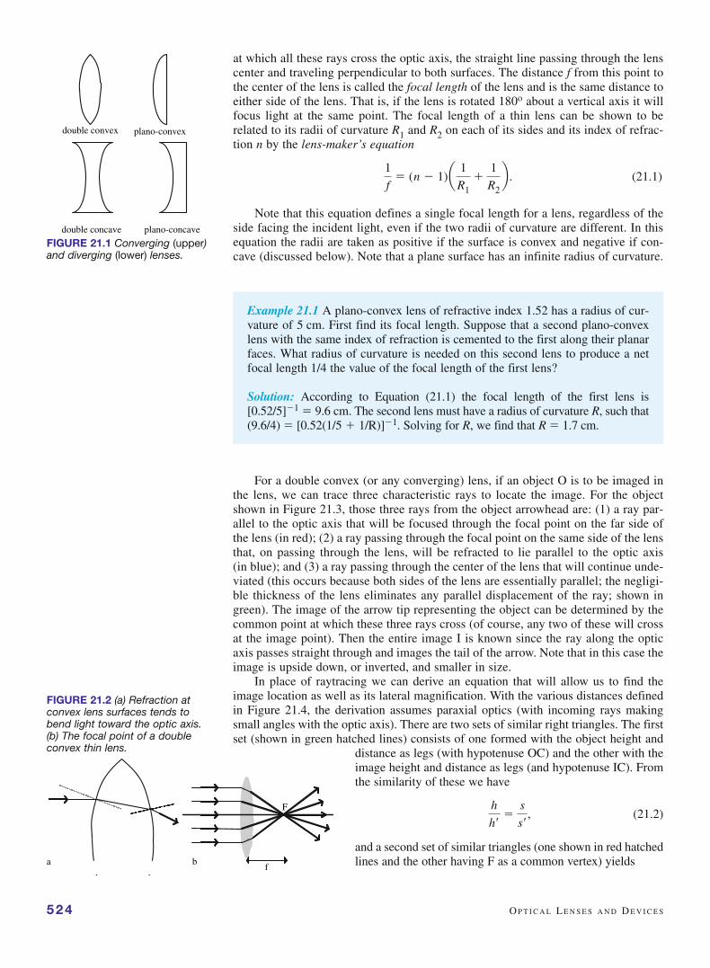
Lenses are usually made either of glass or clear plastic and are ground and pol-ished to have spherical surfaces. Several varieties of two basic forms of lenses exist:converging lenses, those thicker at the center than at the edges, and diverging lenses,those thinner at the center than at the edges (Figure 21.1). Occasionally lenses aremade with cylindrical or even other surface contours for special purposes; these arenot discussed here. Many common lenses, especially those in cameras, are not sim-ple single pieces of glass, but are compound lenses made by cementing many indi-vidual lenses together with a transparent glue that has a similar index of refraction tothat of the glass. We discuss these later, focusing first on simple lenses, those thathave negligible thickness compared to their diameter. These are known as thin lensesand the equations we introduce are limited to such lenses.
Let’s first consider a double convex lens shown in Figure 21.2. Incident rays par-allel to the optic axis will be bent by refraction at both surfaces of the lens toward theoptic axis (Figure 21.2a). For a thin lens there is a common point, the focal point F,
21Optical Lenses and Devices
524 O P T I C A L L E N S E S A N D D E V I C E S
at which all these rays cross the optic axis, the straight line passing through the lenscenter and traveling perpendicular to both surfaces. The distance f from this point tothe center of the lens is called the focal length of the lens and is the same distance toeither side of the lens. That is, if the lens is rotated 180o about a vertical axis it willfocus light at the same point. The focal length of a thin lens can be shown to berelated to its radii of curvature R1 and R2 on each of its sides and its index of refrac-tion n by the lens-maker’s equation
(21.1)
Note that this equation defines a single focal length for a lens, regardless of theside facing the incident light, even if the two radii of curvature are different. In thisequation the radii are taken as positive if the surface is convex and negative if con-cave (discussed below). Note that a plane surface has an infinite radius of curvature.
1
f� (n � 1)a 1
R1�
1
R2b .
double convex plano-convex
double concave plano-concave
FIGURE 21.1 Converging (upper)and diverging (lower) lenses.
Example 21.1 A plano-convex lens of refractive index 1.52 has a radius of cur-vature of 5 cm. First find its focal length. Suppose that a second plano-convexlens with the same index of refraction is cemented to the first along their planarfaces. What radius of curvature is needed on this second lens to produce a netfocal length 1/4 the value of the focal length of the first lens?
Solution: According to Equation (21.1) the focal length of the first lens is[0.52/5]�1 � 9.6 cm. The second lens must have a radius of curvature R, such that(9.6/4) � [0.52(1/5 � 1/R)]�1. Solving for R, we find that R � 1.7 cm.
For a double convex (or any converging) lens, if an object O is to be imaged inthe lens, we can trace three characteristic rays to locate the image. For the objectshown in Figure 21.3, those three rays from the object arrowhead are: (1) a ray par-allel to the optic axis that will be focused through the focal point on the far side ofthe lens (in red); (2) a ray passing through the focal point on the same side of the lensthat, on passing through the lens, will be refracted to lie parallel to the optic axis(in blue); and (3) a ray passing through the center of the lens that will continue unde-viated (this occurs because both sides of the lens are essentially parallel; the negligi-ble thickness of the lens eliminates any parallel displacement of the ray; shown ingreen). The image of the arrow tip representing the object can be determined by thecommon point at which these three rays cross (of course, any two of these will crossat the image point). Then the entire image I is known since the ray along the opticaxis passes straight through and images the tail of the arrow. Note that in this case theimage is upside down, or inverted, and smaller in size.
In place of raytracing we can derive an equation that will allow us to find theimage location as well as its lateral magnification. With the various distances definedin Figure 21.4, the derivation assumes paraxial optics (with incoming rays makingsmall angles with the optic axis). There are two sets of similar right triangles. The firstset (shown in green hatched lines) consists of one formed with the object height and
distance as legs (with hypotenuse OC) and the other with theimage height and distance as legs (and hypotenuse IC). Fromthe similarity of these we have
(21.2)
and a second set of similar triangles (one shown in red hatchedlines and the other having F as a common vertex) yields
h
h¿
�s
s¿
,
a
F
fb
FIGURE 21.2 (a) Refraction atconvex lens surfaces tends tobend light toward the optic axis.(b) The focal point of a doubleconvex thin lens.

O P T I C A L L E N S E S 525
(21.3)
Combining the two equations, we have that s/s�� f/(s�� f ), and aftercross-multiplying and dividing both sides by the product (s s� f ) and sim-plifying the result (try it!), we find the lens equation
(21.4)
We can also invert Equation (21.2) to find an expression for the lateral magnifi-cation m
(21.5)
where the minus sign was introduced so that an inverted image has a negative mag-nification, and an erect image has a positive magnification.
In the case worked out above using ray diagrams, the object distance is greaterthan the focal length and we can see from Equation (21.4) that then because 1/s �1/f, the image distance s� is positive, indicating that the image is real and that theimage will be inverted (because m � 0 in that case). If s� � s the image will be mag-nified, whereas if s� � s the image will be smaller than the object. It is easy to seethat the dividing line occurs when s � 2f, because then s� � 2f as well and the imagewill be “life-size,” but still inverted. If s � 2f, then f � s� � 2f and the image will besmaller, whereas if f � s � 2f, the image will be magnified.
The reciprocal of the focal length for a lens is called its power P, where
(21.6)
Lens power is measured in reciprocal meters which are called diopters(D). Thus, the shorter the focal length of a lens is, the stronger its power. Thediopter unit is mainly used in coding eyeglass lenses, a topic we return to in thenext section.
At this point, if we generalize Equations (21.4) and (21.5) using a set of sign rules,these equations are then valid for all thin lenses no matter what the configuration.These rules are given in Table 21.1. We illustrate their use with a few examples.
P �1
f.
m �h¿
h� �
s¿
s,
1s
�1
s¿
�1
f.
h
h¿
�f
s¿ � f.
3
ff
O
I
1
2
FIGURE 21.3 Raytracing with a thinconverging lens. The image lies atthe intersection of the three num-bered rays (see text for explanationof the construction).
ff
O
s s�
h
h�
F
C
s�-f
I
FIGURE 21.4 Geometry to derivelens equation and magnification(Equations (21.4) and (21.5)).
Table 21.1 Sign Conventions for Thin Lenses
Quantity Convention
s � If object in front* of lens
� If object behind lens
s� � If image behind lens
� If image in front of lens
h, h� � If erect
� If inverted
R1, R2 � If surface is convex
� If surface is concave
f � If converging
� If diverging
* Front and back are with respect to incident light; that is, the front of the lens faces theincident light.

First consider the situation in Figure 21.5 where theobject is closer to the lens than one focal length. In this case,Equation (21.4) predicts that s� will be negative because1/s � 1/f. What does this mean in terms of the image? Thefigure shows raytracing in this case. It is clear that thefocused rays do not converge and that therefore there is noreal image, no place at which a screen can be put to see animage. On the other hand, a viewer on the far side of thelens from the object looking back through the lens will seethe rays appear to emanate from a (virtual) image behind
the lens, to be larger than the object, and to be erect. That the image is larger and erectfollows from Equation (21.5) because s� is greater than s and is negative, makingm � �1 (note the agreement with our sign conventions in Table 21.1). As the objectapproaches the focal point, the virtual image recedes to larger distances and is magni-fied to ever greater size. You may recognize this application of a lens as a magnifyingglass (Figure 21.6). We discuss this situation further after we take a look at the eyein Section 3.
As a second application of the lens equation consider the diverging lensshown in Figure 21.7. According to the lens-maker equation, because the radiiof curvature are both taken as negative, so is the focal length. Therefore, no mat-ter where an object is placed on the left of the lens in the figure, according tothe lens equation, the image will always be virtual with the object appearingsmaller and erect. This is so because with 1/s � 0, when subtracted from �1/| f |,we have that
so that we must always have s� � 0 and |s�| � s. Figure 21.7 shows the raytracing dia-gram for one such situation.
As a final case, we examine the problem of where to put a converging lens inorder to image an object on a screen when the total object to screen distance is fixedat a distance L. In that case (s � s�) � L, and we must find the possible lens loca-tions, or the possible individual s and s� values. Writing the lens equation as
we need to solve for possible s and s� values. Substituting for s� � (L � s)into the above, we have
Solving the quadratic equation, there are two possible solutions givenby
as long as f � L/4 or L � 4f. To each of these values of s, let’s call thems� and s�, both of which are positive, there corresponds a value of s� (s� � L � s) and a magnification m � �(s�/s). Because the two valuess� and s� add up to L, it is clear that the two solutions are s � s� ands� � s� on the one hand and s � s� and s� � s� on the other. In the firstcase, the lens is closer to the screen than to the object and the magnifica-tion is less than 1. The image will be inverted and reduced in size and, of
s �L ; 1L2 � 4fL
2 or s �
L
2;
L
2A1 �
4f
L,
s(L � s) � fL or s2 � sL � fL � 0.
1s
�1
s¿
�s � s¿
ss¿
�1
f, or ss¿ � fL,
1
s¿
� �1
ƒ f ƒ
�1s
526 O P T I C A L L E N S E S A N D D E V I C E S
FI O F
FIGURE 21.5 Raytracing when theobject O is within one focal lengthof a converging lens. The image I isvirtual, erect, and magnified.
FIGURE 21.6 A happy magnifyingglass.

Example 21.2 A 0.2 cm tall object lies 10 cm from a 25 cm focal length magni-fying glass. Find the location, magnification, and size of the image. Is it erect orinverted? Real or virtual?
Solution: By direct substitution into the lens Equation (21.4), using s � 10 cmand f � 25 cm, we find that s� � �16.7 cm. Because s� � 0, we know that theimage is on the same side of the lens as the object and therefore a virtual image.The magnification is given by m � �s�/s � 1.7, so that the object appears to be(0.2)(1.7) � 0.34 cm tall and erect.
O P T I C A L L E N S E S 527
O
I
f
s
s'
f
1
2
3
F F
FIGURE 21.7 Raytracing for adiverging lens to form the image Iof an object O. Ray 1 is parallelto the optic axis and diverges asif it originated at the focal point;ray 2 is aimed at the focal pointon the other side of the lens andemerges parallel to the axis; ray3 passes undeviated through thelens center. The virtual image isfound at the extrapolated locationwhere these rays cross.
As was mentioned above, many lenses are compound or thick lenses composedof multiple lenses cemented together, whereas other optical systems may con-sist of multiple individual thin lenses. Situations in which there are multiplethin lenses can be handled using the formalism of this section. Onebegins by finding the image of the object in the first lens (closest toobject) and then simply treats this image as the object to be imagedby the second lens, and so on. Using the same consistent sign con-vention given in Table 21.1, such problems can be analyzed withoutany new concepts. For example, if the two (thin) lenses are in contact,then we can derive a simple formula for the overall focal length of thecombination as follows. Writing the lens equation for the first lens wehave that
1s1
�1
s1¿�
1
f1,
FIGURE 21.8 The two solutions toimaging an object on a screen afixed distance away from an object.
course, real because it is actually formed on a screen. In the second case, the lensis closer to the object and the real image is enlarged but still inverted (Figure 21.8).With a handheld magnifying glass this is an easy and interesting experiment to try.

with a similar equation for the second lens,
But, using the first image as the object for the second lens meansthat so that on adding the two equations together wefind that
This equation can be interpreted as treating the two lenses in contact with each otheras a single lens with a combined focal length f given by
(21.7)
Most lenses in optical devices are, in fact, compound lenses designed to com-pensate for aberrations and so Equation (21.7) tells how to find the net focallength of the compound lens. We use this idea to analyze the compound micro-scope in the next section. But what is the purpose of cementing multiple lensestogether?
All lenses suffer from various defects in the quality of the image they produce.Collectively these are termed lens aberrations. We can distinguish two classes ofaberrations: monochromatic, those involving a single color, and chromatic, due tothe dispersion of the lens material, refracting different wavelengths (colors) differ-ently due to a variation in index of refraction. There are five major monochromaticaberrations, all of which distort the imaging of a single point of the object to a sin-gle point of the image. One of these, spherical aberration, is simply due to thespherical lens curvature giving rise to distortion when incident rays are far from theoptic axis. In particular, as shown in Figure 21.9, parallel rays from a distant pointsource arriving at different distances from the optic axis will be imaged at slightlydifferent points on the axis, resulting in a blurred image of the point object.Limiting the accepted rays to paraxial rays close to the optic axis with a stop, oraperture, can reduce spherical aberration. The four other monochromatic aberra-tions have to do with off-axis imaging and examples of their images are shown inFigure 21.10.
1. Coma with the comet Hyakutake showing its shape.
1
f1+
1
f2�
1
f.
1s1
�1
s2¿�
1
f1�
1
f2.
s2 ��s1¿,
1s2
�1
s2¿�
1
f2.
528 O P T I C A L L E N S E S A N D D E V I C E S
FIGURE 21.9 Spherical aberration.Parallel rays far off-axis will focus atdifferent distances along the opticaxis (horizontal double-headedarrow). The image in the paraxialfocal plane, shown by the verticalline, will therefore be blurred later-ally (vertical double-headed arrow).
object image
A
BCB’
C’
BB’CC’
C
COMA
FIGURE 21.10 Continued

Chromatic aberrations due to the dispersion of glass result in different focal pointsfor each color (Figure 21.11). The shorter wavelength light (violet end of the visiblespectrum) experiences a larger index of refraction and is therefore refracted more andbrought to a closer focal point. Compound lenses made from a converging and a diverg-ing lens of different index of refraction glasses are designed to minimize chromaticaberration and are known as achromatic lenses (Figure 21.12). The longer optical path
O P T I C A L L E N S E S 529
FIGURE 21.10 The four other monochromatic aberrations, other than sphericalaberration, with schematics and example photos.
DISTORTION
object Image(pincushiondistortion)
Image(barrel
distortion)
objectIdealimage
CURVATURE OF FIELD
Curved imageplane
ASTIGMATISM
object Image-radial linesin focus
Image- tangential
lines infocus
2. Distortion with an example of barrel distortion from a wide-angle camera shot ofa brick wall.
3. Curvature of field with the painting “Anna’s Bedroom” by Scott Kahn illustrat-ing this aberration.
4. Astigmatism with a painting illustrating this aberration.

of the longer wavelength light in the diverging lens seen in the figure compensates forthe smaller index of refraction at these wavelengths and brings the various colors to acommon focus. All good quality cameras are made with achromatic lenses, the betterones having very thick multiple lenses to minimize other distortions as well.
2. THE HUMAN EYE
Eyes are our visual window to the world. They are complex structures that are capa-ble of very high resolution, are extremely sensitive to light, capable even of detect-ing single photons, can give color and depth perception, and adjust to focus onobjects from as close as 10 cm, in young eyes, to “infinity.” In this section we firstdescribe the structure of the eye with the aim of relating its anatomy to its function-ing, as well as to some diseases. Then we focus on the retina and the visual pigmentto describe in some detail the actual transduction of photon energy to an electricalresponse in the optic nerve.
A schematic cross-section of the human eye is shown in Figure 21.13. Startingfrom the outside, the external covering of the eye consists of three layers. Most of theoutermost layer is the sclera, the white of the eye, a tough fibrous layer containingnerve endings but no blood vessels. The sclera covers about 85% of the eyeball,roughly a 2.5 cm sphere, but the front portion consists of a transparent 12 mm diam-eter cornea with an index of refraction of about 1.38. The cornea is the most refract-ing surface in the eye, with the largest index transition from n � 1 in air. The nexttwo inner layers are the choroid, filled with pigments and blood vessels, and theretina, the site of photon detection. Neither of these layers extends into the cornearegion (see Figure 21.13).
At the front end of the eye behind the cornea is a liquid-filled chamber with theaqueous humor, which is continually drained and replaced, bounded also by thelens and the iris. A buildup of pressure in this region can produce a conditionknown as glaucoma, which can lead to blindness. The lens is a double convex lensmade from a crystalline array of 25% protein and 10% lipids, having an index of
refraction of about 1.42. It is one of the few parts of our bodies thatare preserved without any turnover of their cells. With age, or dis-ease, the lens loses its perfect crystallinity and develops defectsthat scatter light. These are known as cataracts and, when suffi-ciently large, can adversely affect vision by “clouding” the eye, orscattering light just as if you tried to view the world through a thinlayer of milk. The shape of the lens is controlled by ciliary musclesthat can change its focusing ability in a process known as accom-modation. Normally, without any shape change of the lens, we canfocus on objects from about 20 feet to infinity. This ability is dueto the finite thickness of the photon detection region allowing light
530 O P T I C A L L E N S E S A N D D E V I C E S
CHROMATIC ABERRATION FIGURE 21.11 Chromatic aberra-tion, showing the effect of disper-sion on the focusing of differentcolored light in a white light beam.Shorter wavelengths experiencegreater refraction due to the higherindex of refraction.
ACHROMATIC LENS
FIGURE 21.12 Using an achro-matic lens (compound lens cor-rected for chromatic aberration)there is much less chromatic blur.

to be focused at slightly different distances (see below). To seeobjects closer than that distance, the eye cannot remain relaxed,but the lens must change shape, thickening to give a tighterfocus.
The iris serves as an adjustable aperture and is pigmented, giv-ing the eye its characteristic coloring. The central opening, known asthe pupil, is the photon entrance path. Filling the eyeball is a gel-likematerial, the vitreous humor, which is more or less permanent. Sixpairs of muscles control the movement of the eyeball in its socket,allowing us to focus images of interest on the highest acuity regionof the retina, the fovea. This region of the retina, also known as themacula, has only cones, the photon receptor cells responsible forcolor vision, with each cone having a direct connection to a differ-ent optic neuron, or nerve cell. The macula therefore has the highestspatial resolution on the retina; outside the fovea there are roughly10 cones per neuron connection or 125 rods, the other type of pho-ton receptor, per neuron. These neurons collect in the optic disc,creating a blind spot with no visual pigment, and lead to the opticnerve bundle.
Before we consider the photon detection process on the retina in more detail,consider the overall optical arrangement of the eye. As shown in Figure 21.14, par-allel rays of light (from an object at “infinity”) are focused by the relaxed lens to apoint on the retina some 2 cm behind the lens, in fact at the central fovea which lieson the visual axis. An object at a large but finite distance is focused onto the retinaas an inverted image. Our brain interprets this inverted image as erect. The totalequivalent lens of the eye is a thick lens system, composed of the cornea, aqueoushumor, and lens, subject to all of the aberrations mentioned in the last section. Onefunction of the iris is to reduce the aperture size to limit incoming rays to be parax-ial, thus reducing aberrations.
Often the eyeball is either elongated along the visual axis (myopia, or near-sightedness) or shortened in that direction (hyperopia, or farsightedness). A thirddefect in which the cornea is not spherical, but oval in shape, having different focus-ing properties along two different orthogonal directions, is known as astigmatism.All three of these defects can be corrected for by placing lenses in front of the eye(either as eyeglasses or contact lenses). Figure 21.15 shows ray diagrams for eachof these, together with their corrections through the use of a lens. In myopia (top),parallel rays are brought to a focus in front of the retina (hence the name near-sightedness), blurring the image on the retina. By using a diverging lens, the imagecan be formed on the retina. The worse the myopia, the greater the power of the cor-rective lens needed. In hyperopia (middle), parallel rays would be focused behindthe retina (far-sightedness) and so have not yet converged to form a clear image onthe retina. A converging lens will move the focal point onto the retina. Again, theworse the eye’s vision is, the stronger power corrective lenses needed. Inexpensive“reading glasses,” simply matched converging plastic lenses, are sold in variousdiopter ratings for several dollars and are usually adequate for reading purposes.Astigmatism (bottom) produces a distortion in imaging so that two perpendicularlines cannot be both brought into focus. A cylindrical lens that focuses light alongonly one axis can correct this defect.
T H E H U M A N E Y E 531
FIGURE 21.13 The human eyein cross-section.
Example 21.3 Suppose the focal length of a person’s eye is 3.0 cm when fullyrelaxed (looking at a distant object). If the person’s retina is 3.3 cm behind theeye lens (a nearsighted eye compared to the normal distance of 3.0 cm), whatmust be the focal length of the corrective lenses so that this person can see“objects at infinity?”
FIGURE 21.14 A distant objectimaged on the retina.

Solution: Using the thin lens equation with s � � and we find aneffective focal length of 3.3 cm needed. Because the effective focal length ofsuch a two-lens system (the lens of the eye and the corrective lenses) is given,from Equation (21.7), by
we can find the focal length of the needed lens to be
(or in diopters, (1/�.33 m) � �3 D).
flens � a 1
feffective�
1
feyeb�1
� a 1
3.3�
1
3.0b�1
� � 33.0 cm
1
feffective�
1
flens�
1
feye,
s¿ � 3.3 cm,
532 O P T I C A L L E N S E S A N D D E V I C E S
There are some interesting points to be made about nearsightedness. For exam-ple, if the near point of the normal eye is 25 cm (smin) and the distance to the retinais 3 cm (s�), then the minimum focal length of the normal eye is 2.7 cm (from
Normal eyes produce an inverted real image on the retina that is times as large as the object. Let’s assume the nearsighted person
in Example 21.3 has the same minimum focal length. Then, without corrective lenses,at closest focus
which leads to smin � 14.9 cm. Nearsighted people can see clearly closer to their eyesthan normal-sighted persons; they have a smaller near point, which is the closest dis-tance an object can be brought into focus, without corrective glasses. The size of thereal image for this case is 3.3 cm/14.9 cm � 0.22, almost twice as large as that of thenormal-sighted person! Nearsighted people who are stamp or coin collectors have agreat advantage over normal-sighted persons; they often don’t need magnifyingglasses to see fine details.
Unfortunately for the nearsighted, this close vision advantage vanishes whenthey put on corrective lenses. Suppose the person above is wearing the �3 D correc-tive lenses designed for distance vision and is looking at an object 25 cm away. The
�3 D lens turns out to create a virtual image 14 cm in front of thelens that serves as the object for the eye’s lens, using
But, that is approximately the closest the bare eye lens can focus,therefore with corrective lenses on, the person can no longer see asclose as without them. (An object 14 cm away would form a vir-tual image only 10 cm in front of the glasses, too close to be infocus.) Note also that the virtual image formed by the correctivelenses is smaller than the object by a factor of 14 cm/25 cm �0.56. This reduction cancels the magnification advantage the near-sighted person enjoyed, too. In fact, because the corrective lens isdiverging, it always forms a reduced size virtual image in front of
s¿ � a1
f�
1sb�1
� a � 3 �1
0.25b�1
� � 0.14 m.
1
2.7=
1smin
+
1
3.3,
3 cm/25 cm � 0.12m � s¿/s �
1
f�
1s
�1
s¿
b .
Near-sighted eye Near-sighted eye, corrected
Far-sighted eye Far-sighted eye, corrected
Astigmatic eye Astigmatic eye, corrected
FIGURE 21.15 Three commonfocusing problems with the eye andtheir correction with eyeglasses.

the real object. The eye uses this image as its object and so nearsighted people withcorrective lenses always perceive objects to be both closer to them and smaller, com-pared with what a normal person sees.
As the eye ages, the lens shape becomes more resistant to change by the cil-iary muscles and so the eye cannot accommodate as well to bring close objectsinto focus. This weakening of accommodation is known as presbyopia. In the youngeye, the near point can be as short as 7 cm. With age, the near point moves fartheraway due to presbyopia, having a mean of about 1 m for a 60 year old individual.Producing a similar effect as hyperopia, this can be corrected with a converging lens.People with myopia will often see an improvement in their vision with age due topresbyopia and will often require bifocal lenses with the lower portion made con-verging for reading or close vision and the upper portion made diverging for dis-tance vision.
The structure of the retina is shown in cross-section in Figure 21.16. Note thestriking fact that incident light must travel through the network of nerve cells (retinalganglion cells) before reaching the photoreceptors, lying partly immersed in a layerof pigmented cells. Fortunately these cells are transparent, but only about 50% of thelight that strikes the cornea gets to the retina, and only about 20% of that gets to thelight detecting cells. These cells, the rods and cones, permanent and not replaced overtime, are, however, 100% efficient. Light that is not absorbed by the photoreceptors
T H E H U M A N E Y E 533
FIGURE 21.16 The human retina. (top) Light passes through a network of nerve cellsfrom the bottom of this drawing before being detected by the rods and cones. (bottom)Fluorescence microscopy image of the retina.

is subsequently absorbed by a layer of pigmented cells toprevent stray reflections of light within the retina. There areabout 125 million rods and 7 million cones on the retina dis-tributed such that only cones are at the central fovea, wherevision is most acute (Figure 21.17). The rods and cones arenamed by their shapes, but are somewhat similar in overallstructure (Figure 21.18).
There is an inner segment, filled with mitochondriato supply the energy needed for the light transduction,through which the light must also pass. The retina con-sumes the greatest amount of oxygen per unit weight ofany tissue in the body. Inner and outer segments are con-nected through a thin cilialike portion containing micro-tubules. Light transduction takes place in the outersegments, the rod outer segments having been studied muchmore thoroughly than those of the cone. They are each 20m long and 2 m in diameter and contain stacks of roddiscs that are membranes containing the visual pigmentrhodopsin, with about 105 rhodopsin molecules per m2 ofsurface area.
Rhodopsin consists of two parts: a protein portion with348 amino acids, known as opsin, and a smaller hydrocar-
bon part C20H28O, a derivative of vitamin A known as retinal, the light-absorbingportion (Figure 21.19). The structure of retinal is shown in Figure 21.20. Thereare two possible sterioisomers, or conformations, of retinal: 11-cis-retinal foundin the dark and all-trans-retinal that nearly instantaneously forms after the absorp-tion of a single photon. With the advent of femtosecond (10�15 s) laser pulses,this first step in the vision process, the isomerization of retinal, has been found tooccur within about 500 femtoseconds. Subsequent to this initial conformationalchange there is a sequence of conformational steps, discovered using pulsedlaser spectroscopy, and other events that lead to an eventual electrical signal at theneuron. Each photon absorbed by a rhodopsin leads to the hydrolysis of over100,000 molecules of cyclic GMP, the crucial signaling molecule in the subsequenttransduction. The reduction in cyclic GMP, needed to keep Na� channels openin the rod membrane, causes the eventual polarization of the membrane and elec-trical signal.
The electrical signal that is sent from the retina to the brain over the optic nerve isnot simply the sum of all rod and cone firings. Somehow the activity of the many rodand cone interconnections “preprocesses” information about the light falling on them
so that a significant part of “seeing” occurs prior to what goeson in the visual cortex of the brain. It takes time to performthe preprocessing of visual information in the rod and conenetworks, perhaps 0.1–0.2 s, a time that matches the responsetime of our nervous system.
We do not see the instantaneous values of the elec-tric fields of the EM light waves, which vary about 1015
times per second. Rather we see the effects of electricfields that have been averaged over many cycles of oscilla-tion. In fact, the signal sent from the eye to the brain isnot directly related to E fields, but rather to the averageintensity, proportional to E2 averaged over many cycles.Now, rods and cones may detect EM intensity, but notequally well at all frequencies. The retinal molecule actslike a damped oscillator. When driven by the oscillatingE field of the light, these molecules vibrate resonantly atdifferent driving frequencies. There are three kinds of cone
534 O P T I C A L L E N S E S A N D D E V I C E S
FIGURE 21.17 Hexagonally packedcone cells at the fovea section ofthe retina in a living human eye.The image is taken at a locationabout 300 m from the foveal cen-ter (which is equal to about 1 degree of visual angle) and it isabout 150 m across. The smallspots are single cone photorecep-tors which, at this location are sep-arated by about 5 m. The darkshadow is that of a blood vesselwhich runs above the photorecep-tor layer.
FIGURE 21.18 Cone cells of thehuman retina.

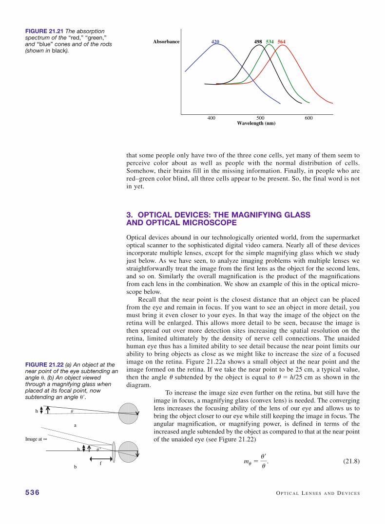
cells (with three different resonant frequencies close to “red,” “green,” and “blue”)and one kind of rod cell, with a resonant peak response between “green” and “blue.”
The absorption spectrum of rhodopsin shown in Figure 21.21 indicates that dark-adapted rods are most sensitive (have their strongest absorption) in the green-blue at500 nm. In strong light this shifts slightly to 550 nm, but with a single absorptionspectrum rods are not able to distinguish all of the different colors we can see inbright light. Cones are much less sensitive to light (the figure does not show thisbecause the absorption peaks are all normalized); in fact the cones effectively “turnoff” in dim light. In dim light there is little distinction between colors; everythingappears gray.
In bright light, the cones take over. They have three different types of visual pig-ments, each having a maximum absorption at a different visible wavelength, corre-sponding to a different color. It has long been known that (almost) any light colorcan be represented as a sum of three “primary” light colors: red (R), green (G), andblue (B). The RGB system is the basis for color TV, for example. On a color TVscreen, each pixel is divided into an R, a G, and a B subpixel. Three electron beamssweep rapidly across the screen lighting each pixel with a certain amount of R, ofG, and of B.
Clearly it is tempting to explain the RGB color system in terms of the threedifferent cone cells. Undoubtedly, there is some connection between the two, butthe connection must be fairly subtle, and, as yet, is still not worked out. Onereason for this situation is that the “R” cone cells actually have their responsemaximum at a frequency that is closer to yellow than to red. A second reason is
T H E H U M A N E Y E 535
FIGURE 21.19 A rod cell on leftwith a model of the seven-helixrhodopsin with the front twohelices of opsin cut away toshow the retinal molecule at theactive site.
FIGURE 21.20 The chemicalstructure of retinal, thelight-sensitive portion of rhodopsin.
536 O P T I C A L L E N S E S A N D D E V I C E S
that some people only have two of the three cone cells, yet many of them seem toperceive color about as well as people with the normal distribution of cells.Somehow, their brains fill in the missing information. Finally, in people who arered–green color blind, all three cells appear to be present. So, the final word is notin yet.
3. OPTICAL DEVICES: THE MAGNIFYING GLASS AND OPTICAL MICROSCOPE
Optical devices abound in our technologically oriented world, from the supermarketoptical scanner to the sophisticated digital video camera. Nearly all of these devicesincorporate multiple lenses, except for the simple magnifying glass which we studyjust below. As we have seen, to analyze imaging problems with multiple lenses westraightforwardly treat the image from the first lens as the object for the second lens,and so on. Similarly the overall magnification is the product of the magnificationsfrom each lens in the combination. We show an example of this in the optical micro-scope below.
Recall that the near point is the closest distance that an object can be placedfrom the eye and remain in focus. If you want to see an object in more detail, youmust bring it even closer to your eyes. In that way the image of the object on theretina will be enlarged. This allows more detail to be seen, because the image isthen spread out over more detection sites increasing the spatial resolution on theretina, limited ultimately by the density of nerve cell connections. The unaidedhuman eye thus has a limited ability to see detail because the near point limits ourability to bring objects as close as we might like to increase the size of a focusedimage on the retina. Figure 21.22a shows a small object at the near point and theimage formed on the retina. If we take the near point to be 25 cm, a typical value,then the angle subtended by the object is equal to � h/25 cm as shown in thediagram.
To increase the image size even further on the retina, but still have theimage in focus, a magnifying glass (convex lens) is needed. The converginglens increases the focusing ability of the lens of our eye and allows us tobring the object closer to our eye while still keeping the image in focus. Theangular magnification, or magnifying power, is defined in terms of theincreased angle subtended by the object as compared to that at the near pointof the unaided eye (see Figure 21.22)
(21.8)mu �u¿
u.
Absorbance
Wavelength (nm) 400 500 600
420 498 534 564
FIGURE 21.21 The absorptionspectrum of the “red,” “green,”and “blue” cones and of the rods(shown in black).
θ �
θh
f
a
b
Image at ∞
h
FIGURE 21.22 (a) An object at thenear point of the eye subtending anangle . (b) An object viewedthrough a magnifying glass whenplaced at its focal point, nowsubtending an angle �.

Using a magnifying glass with a relaxed eye focusedat infinity and with the eye directly behind the magnifier, avirtual image at infinity is formed when the object isplaced at the close focal point of the magnifier. Underthese conditions � � h/f as shown in the diagram and wecan write the angular magnification as
(21.9)
The smaller the focal length of the lens, the greater is the magnification seenby the eye. The exact position of the object relative to the focal point of the mag-nifier turns out to be unimportant, only changing the magnification by a smallamount. The eye accommodates these small changes to make the image clear onthe retina resulting in a small increase in magnification. The maximum magnifi-cation occurs when the image viewed through the magnifying glass occurs at thenear point of the eye.
To obtain higher magnification still, a compound microscope can be used.Figure 21.23 shows a schematic drawing of such a microscope with two lenses, aneyepiece that functions as a magnifying glass and an objective lens that further mag-nifies the object. The overall magnification is the product of that produced by eachlens. The object is placed just outside the focal point of the objective, s ~ fobj, so thatan inverted real image is formed with a lateral magnification of
from Equation (21.5). This image then acts as the object for the eyepiece, adjusted toplace the final virtual image at infinity, so that the eye can be relaxed as it viewsthe image. In this case, we can write that where L is the distancebetween the lenses, as shown in the diagram. The overall magnification compared tothat at the near point with the unaided eye is then
(21.10)
because feye is generally much smaller than L, where all distances aregiven in cm. Usually the short focal length lenses of a microscope arecompound lenses designed to eliminate aberrations. Magnifications ofover 1000� are readily obtained.
Figure 21.24 shows a photo of a basic compound microscope with itsthree main features: the built-in light source or condenser, providing auniform brightness with the use of lenses; a stage, designed to securelyhold the sample and usually to move it about in the horizontal plane; andthe barrel of the microscope, holding the lenses and usually allowing dif-ferent objectives with different focal lengths to be used. Microscopy hasdeveloped substantially in the recent past. The use of high-sensitivityvideo cameras and electronic image-processing techniques, as well as thedevelopment of several new types of microscopy discussed in Chapter 24,have broadened the versatility of the microscope in studying fundamentalprocesses in biology.
m � mobj meye � aL � feye
fobjb a25 cm
feyeb L
25 cm # L
fobj feye,
s¿ � 1L � feye2,
mobj �s¿
s�
s¿
fobj,
mu �
ah
fb
a h
25 cmb
�25 cm
f.
O P T I C A L D E V I C E S : T H E M A G N I F Y I N G G L A S S A N D O P T I C A L M I C R O S C O P E 537
feye
fobj
L
Image at ∞
FIGURE 21.23 Optics of a simplecompound microscope. The objectis placed just outside the focalpoint of the objective lens so thatan enlarged, inverted real image isformed just inside the focal point ofthe eyepiece lens. Its image is afurther enlarged virtual imageviewed at infinity by a relaxed eye.
Dual eyepieces
Objective lenses onrotating mount
Light source
x–y moveable stage
FIGURE 21.24 A basic compoundmicroscope.

QUESTIONS1. Distinguish carefully between a converging and
diverging lens, a thin and a thick lens, and a real anda virtual image. Which combinations do not exist?For example, is there a thin diverging lens that formsa real image?
2. Carefully define all the symbols in the lens-maker equa-tion. In a thin double convex lens made from n � 1.5glass with both sides having 25 cm radii of curvature,what is the predicted focal length?
3. Review the raytracing algorithm for finding the imageof a (real) object through a thin lens. Distinguish thefour cases of a converging lens with object closer orfarther than the focal length, and a diverging lens withthe object closer or farther than a focal length. Make asketch of an example of each case. Classify each caseaccording to whether the image is (erect or inverted),(real or virtual), (magnified more or less than 1�), and(closer or farther than a focal length from the lens).
4. Consider the object–convex lens–real image configura-tion. If one places one’s eye at the image location, onewill not see the image; however, if one moves the eyefarther back, away from both the lens and the imagelocation, the image will become visible. Why is this?
538 O P T I C A L L E N S E S A N D D E V I C E S
5. Compare the (real) image of a person formed by a con-verging lens to the (virtual) image of that person in aplane mirror. In which is up/down reversed, left/rightreversed, and the magnification possibly changed?
6. In applications where a large light source is to befocused, such as a lighthouse, stage lighting in a the-ater, or an overhead projector, both a large diameterand a thick lens are needed. Fresnel, realizing that therefraction occurs at the glass surface, designed a lens(now called a Fresnel lens) that keeps the large cur-vature and lens size, but collapses the lens down to anearly planar lens by removing the glass interior. Thisovercomes the problem of weight, bulk, and cost ofsuch a glass lens. Based on the figure below explainhow this lens works.
CHAPTER SUMMARYThin optical lenses have a focal length that is given bythe lens-maker formula
(21.1)
where n is the index of refraction of the lens materialand R1 and R2 are the radii of curvature of the twofaces of the lens. An object located a distance s fromthe lens will produce an image through a thin lensof focal length f at a distance s� given by the lensequation,
(21.4)
The lateral magnification of the image is
(21.5)
These three equations work under a wide variety ofconditions if one uses the sign conventions of Table 21.1.
m �h¿
h� �
s¿
s.
1s
�1
s¿
�1
f.
1
f� (n � 1)a 1
R1�
1
R2b ,
If two thin lenses are placed in contact, the overall focallength of the pair is given by
(21.7)
The structure, optics, and detection properties ofthe eye are discussed in Section 2 of this chapter witha discussion of some common vision disorders andtheir correction with lenses.
A simple magnifying glass of focal length f willproduce a virtual image with a magnification given by
(21.9)
where 25 cm is taken as the near point of the eye.Similarly, the overall magnification of a compoundmicroscope, made from an eyepiece and an objectivelens, is given by
(21.10)
where L is the lens separation distance.
m � mobj meye L
25 cm # L
fobj feye,
mu �25 cm
f,
1
f1+
1
f2=
1
f.

7. What is the physical origin of chromatic aberration ina thin lens? Of spherical aberration? Which rays arebrought to focus closer to the lens: blue or red? parax-ial (those parallel to and close to the optic axis) or off-axis rays?
8. Why does closing down the iris reduce aberrations ofthe lens of the eye?
9. One way to correct the eye for myopia is with lasersurgery called photorefractive keratectomy (PRK) inwhich the cornea is reshaped so that light from a dis-tance object focuses on the retina instead of in frontof the retina. What do you think the laser proceduredoes to the cornea? This surgery will not correct forthe age-related presbyopia that leads to the need forreading glasses.
10. Discuss the origin of presbyopia and the need forreading glasses as one ages.
11. Which photoreceptors, rods or cones, give us ourmost acute vision? Our color vision? Our nightvision?
12. Explain in basic terms why the magnification of amicroscope (or any two-lens system) is equal to theproduct of the magnifications of the objective andeyepiece.
MULTIPLE CHOICE QUESTIONS1. A light-emitting object is 10 cm from a thin lens. An
upright virtual image is formed 20 cm behind theobject. Which of the following is true? The lens has afocal length of (a) �6.7 cm, (b) �15 cm, (c) �15 cm,(d) �20 cm.
2. The distance from the eye’s lens to the retina for agiven person is 3.0 cm. This person clearly sees anobject 27 cm in front of his eye. The focal length ofthe eye’s lens in this case is (a) �2.7 cm, (b) �3.0 cm,(c) �3.4 cm, (d) �3.4 cm.
3. A 10 cm tall object 25 cm from a converging lens hasits real image 50 cm from the lens. The object appearsto be (a) 20 cm tall and erect, (b) 5 cm tall andinverted, (c) 5 cm tall and erect, (d) 20 cm tall andinverted.
4. A light source with an arrow pointing up is placed atthe zero mark on an optical bench. A convex lens ofunknown focal length is placed with its center at the30 cm mark on the bench. A focused image appearson a collector when placed at the 60 cm mark on thebench and nowhere else. What must be true about theimage? It is (a) real and inverted, (b) real and upright,(c) virtual and inverted, (d) virtual and upright.
5. The focal length of the lens in the previous ques-tion must be (a) �15 cm, (b) �15 cm, (c) �30 cm,(d) �60 cm.
6. Suppose a concave lens is inserted at the 15 cm markon the bench in question 4. What would you haveto do to the collector to find a focused image now?(a) Leave it at 60 cm. (b) Move it to some position
Q U E S T I O N S /P R O B L E M S 539
between the 30 cm mark and the 60 cm mark. (c) Moveit to a position farther out than the 60 cm mark. (d) Youcan’t move the collector anywhere to get a focusedimage because no real image will be formed by thisarrangement of lenses.
7. In drawing a ray diagram for a converging lens withan object farther away than a focal length which ofthe following is not a correct ray to draw: (a) a rayparallel to the optic axis deflects at the lens to appearto come from the near focal point, (b) a ray parallel tothe optic axis deflects at the lens to go through thefocal point on the far side of the lens, (c) a ray goingthrough the near focal point deflects at the lens andemerges from the lens parallel to the optic axis, (d) aray straight through the lens center.
8. A plano-convex lens of crown glass with a radiusof curvature of 50 cm has a focal length of (a) 1.0 m,(b) 0.5 m, (c) 2.0 m, (d) �1.0 m.
9. A double concave lens of crown glass with radiiof curvature magnitudes of 25 cm and 50 cm has afocal length of (a) 0.33 m, (b) �3 m, (c) �0.33 m,(d) �33 m.
10. Chromatic aberration in lenses is due to (a) disper-sion, (b) interference, (c) total internal reflection, (d)varying degrees of absorption of different colors oflight.
11. Which of the following best describes nearsighted-ness? The lens in the eye produces an image of anobject (a) 5 m away that would form behind the retina,(b) 5 m away that forms in front of the retina, (c) 10cm away that would form behind the retina, (d) 10 cmaway that forms in front of the retina.
12. Without corrective lenses a woman can see an objectclearly no closer than 0.5 m from her face. With cor-rective lenses she can see the object clearly as closeas 0.1 m from her face. When the object is at 0.1 mher corrective lenses must form a (a) real image 0.5 min front of her face, (b) real image 0.1 m in front ofher face, (c) virtual image 0.5 m in front of her face,(d) virtual image 0.1 m in front of her face.
13. A prescription for corrective lenses reads �5 D foreach lens. These corrective lenses are (a) divergingwith focal length equal to 5 m, (b) diverging withfocal length equal to 0.2 m, (c) converging with focallength equal to 5 m, (d) converging with focal lengthequal to 0.2 m.
14. It is essentially impossible for humans to react to avisual stimulus in less than 0.1 s. This is because thatis about how long it takes (a) light to pass from thelens of the eye to the retina, (b) light to make onecomplete cycle of oscillation, (c) molecules in thecones to complete one cycle of vibration when theyare excited by light, (d) firing from the retinal cells tobe processed before being sent to the brain.
15. In very dim light you can see an object better by look-ing at it out of the corner of your eye than straight on.That is because (a) cones are more concentrated on

the periphery of the retina than rods and cones func-tion better in dim light, (b) cones are more concen-trated on the periphery of the retina than rods androds function better in dim light, (c) rods are moreconcentrated on the periphery of the retina than conesand cones function better in dim light, (d) rods aremore concentrated on the periphery of the retina thancones and rods function better in dim light.
16. Color vision is due to (a) the varying sensitivity ofdifferent rhodopsins to different wavelengths of light,(b) three different kinds of rod cells, (c) the disper-sion of the lens of the eye, (d) the pigmented epithe-lial cells.
17. A magnifying glass produces an image that is (a)upright and real, (b) inverted and real, (c) upright andvirtual, (d) inverted and virtual.
18. Light entering the eye passes through the followinglayers in the order (a) lens, cornea, ganglion cells,retina, (b) cornea, lens, ganglion cells, retina, (c) lens,cornea, retina, ganglion cells, (d) cornea, lens, retina,ganglion cells.
PROBLEMS1. Sunlight can be focused on the ground by a lens when
it is held 24 cm above the surface. What is the powerof the lens?
2. A �5.0 diopter lens is used to magnify an insectwhen held 12 cm away. Describe the type of image,its position, and lateral magnification. Draw a ray dia-gram sketch.
3. A pinhole can function as a “lens”. Consider a boxwith a very small hole in one side. The hole admitslight from any and all points outside to the inside butfrom any one point outside only the ray directed at thehole can enter the box. Show with a diagram theimage of the object obtained by the light admitted bythe pinhole. What is the magnification? Such boxescan be used as cameras, provided they are mountedon a rock-solid surface. Film exposures are typicallymany seconds or minutes and the image quality canbe superb.
4. An old-fashioned box camera has a fixed lens and adepth of 15 cm. Suppose the camera lens is designedto be optimal for taking photographs of objects 3 maway. What is the focal length of the lens?
540 O P T I C A L L E N S E S A N D D E V I C E S
the lens x, in order that the camera be able to takesharp photographs of objects positioned anywherefrom 50 cm to infinity, measured from the front sur-face of the camera body.
camera
3 m 15 cm
cheese
5. A camera has a lens with adjustable position. Thecamera depth d � 4 cm. Determine the focal lengthof the lens and the necessary allowable extension of
50 cm
x
d
Subject at minimum
object distance
6. How far from its infinity setting must a 35 mm lensbe moved so that it produces a sharp image of anobject 3 m away?
7. Suppose the image of a creature swimming in a dishof water is projected onto a screen. The distance fromthe dish to the lens is 36 cm and the screen is 4.5 maway from the mirror and lens. (The mirror simplyredirects the light from the lens to the screen. Treatthe distance between the lens and mirror as smallenough so that it can be neglected in the specificationof the image distance. Thus, object distance sv is 36 cmand image distance sh is 4.5 m.)
sv
sh
(a) What is the focal length of the projection lens?(b) If the creature swims at 1 cm per second in the
dish, how fast does the image move on the screen?8. A 35 mm film slide projector has a projection lens
with a focal length of 135 mm.(a) Where should the slide be placed if the projection
screen is 3 m away from the projection lens?(b) What is the magnification?(c) Now for the hard part (judging by the difficulty
that even well-educated lecturers have with thisone in practice). If we want to get a true (upright,nonreversed) image of the slide on the screen,how should the slide be placed into the projector?Should it be flipped upside down? Should it bereversed left and right? Should the slide beinserted backwards? (What does “backwards”mean here?)
9. A quick and easy way to get an approximate determi-nation of the focal length of a convex lens is to mea-sure the distance from the lens to an image of a lightor other bright source some distance away. Supposeone has a lens that in fact has a focal length of 10 cm.

A fluorescent ceiling light with a grill cover is 1.5 mabove the lens and a student is able to see an image ofthe lighting fixture grill on the back of his hand. Hedeclares that the focal length of the lens is equal to thedistance between lens and hand. Calculate the actualhand–lens separation distance for a sharp image andshow that the error in the value of the focal lengthdetermined this way is less than 10%. Error � [(focallength � distance measured)/focal length] � 100%.
Q U E S T I O N S /P R O B L E M S 541
(unit magnification). Consider an object for which animage of the same size is desired, exactly 1 m away.(a) What is the focal length and the location of the
single lens that will accomplish this?(b) The image of the object, using one lens, will be
inverted. A relay system using two identical con-vex lenses will invert the inversion, yielding anupright image. Design such a system for the sameinitial situation as in the previous part.
12. If a certain microscope has an eyepiece with 12�magnification and it is desired to view a specimenwith an overall magnification of 60�, what is thepower of the objective that must be used?
13. The magnification of a compound microscope can beslightly improved if the final image is not at infinitybut rather at the near point of the eye. Derive the for-mula for the magnification under this condition. Thisarrangement tends to produce eye strain because theiris must be under tension to have the lens of the eyeconstantly focusing at the near point.
14. Tom Cruise catches a reporter shooting pictures of hisdaughter at his home. He claims the reporter was tres-passing. To prove his point, he gives as evidence thefilm the police took from the reporter. His daughter’sheight of 0.62 m is 2.89 mm high on the film, and thefocal length of the camera lens that the police seizedwas 210 mm. How far away from the baby was thereporter standing? Could the reporter be trespassing?
10. Consider a convex lens of focal length 20 cm.Calculate the image distance for each of the follow-ing object distances: �, 4 m, 2 m, 1 m, 80 cm, 60 cm,40 cm, 20 cm.
11. It is often necessary to convey or relay the image ofan object while keeping the image size unchanged