opportunities to create an optimal beam design for the
TRANSCRIPT
Opportunities to create an optimal
beam design for the 40kt experiment
Vaia Papadimitriou
Accelerator Division Headquarters – Fermilab
ELBNF proto-collaboration meeting at Fermilab
22-23 January, 2015

Outline
• Recent upgrades to the Fermilab Accelerator Complex
• Future plans for the Accelerator Complex
• Where we are with the beamline design for ELBNF
• Opportunities to create an optimal beam design
• Summary and conclusions
• A few facts and discussion on:
– Do we need 700 kW prior to 2024 pointing to SURF?
2 V. Papadimitriou | ELBNF Collaboration Meeting 01/22/2015

Fermilab Accelerator Complex
5 Nov 14 J.Strait| Future Plans in the Americas 3
MI tunnel
Main Injector
NuMI line
Recycler
12 Booster batches are injected and slipped stacked in Recycler while MI is accelerating, thus saving
injection time. This and a few more upgrades will allow 700 kW on the NuMI/NOvA target

Proton Improvement Plan-II (PIP-II) Site Layout (provisional)
4
800 MeV SC Linac
V. Papadimitriou | ELBNF Collaboration Meeting

Flexible Platform for the Future (PIP-III)
• Opportunities for expansion include full energy (8 GeV) linac
or RCS
5
V. Papadimitriou | ELBNF Collaboration Meeting 01/22/2015
I
3-8 GeV
0.8-3.0 GeV

6
Beamline for the new Long-Baseline Neutrino Facility
A design for a new Beamline at Fermilab is under development, based
on work done for the LBNE Project, which will support the new Long-
Baseline Neutrino Facility.
• Directed towards the Sanford Underground Research Facility (SURF) in
Lead, South Dakota, 1300 km from Fermilab.
• The primary beam designed to transport high intensity protons in the energy
range of 60-120 GeV to the LBNF target.
• A broad band, sign selected neutrino beam with its spectrum to cover the 1st
(2.4 GeV) and 2nd (0.8 GeV) oscillation maxima => Covering 0.5 ~ 5.0 GeV
• All systems designed for 1.2 MW initial proton beam power (PIP-II, ~2024).
(Were planning to start at 700 kW a year ago).
• Facility is upgradeable to 2.4 MW proton beam power (PIP-III).
• We are currently assuming 20 year operation of the Beamline, where for
the first 5 years we operate at 1.2 MW and for another 15 years at 2.4 MW.
• The lifetime of the Beamline Facility including the shielding is assumed to be
30 years.
01/22/2015 V. Papadimitriou | ELBNF Collaboration Meeting
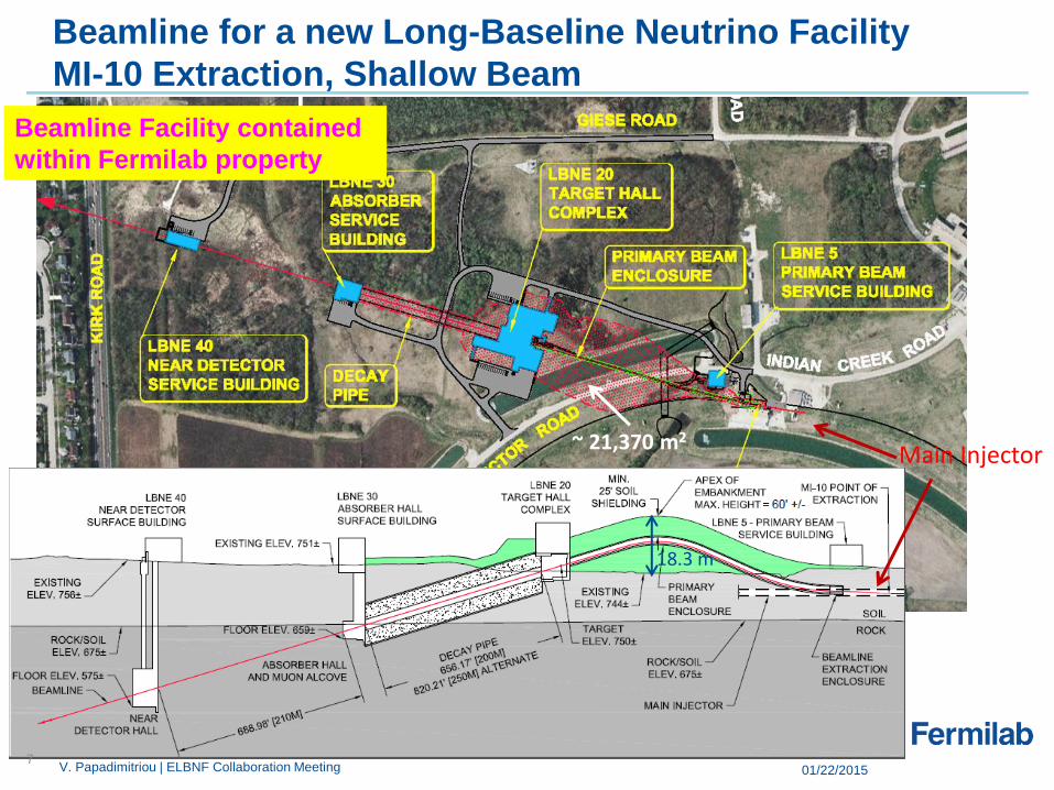
Beamline for a new Long-Baseline Neutrino Facility
MI-10 Extraction, Shallow Beam
Main Injector
Beamline Facility contained
within Fermilab property
~ 21,370 m2
18.3 m
7 01/22/2015 V. Papadimitriou | ELBNF Collaboration Meeting
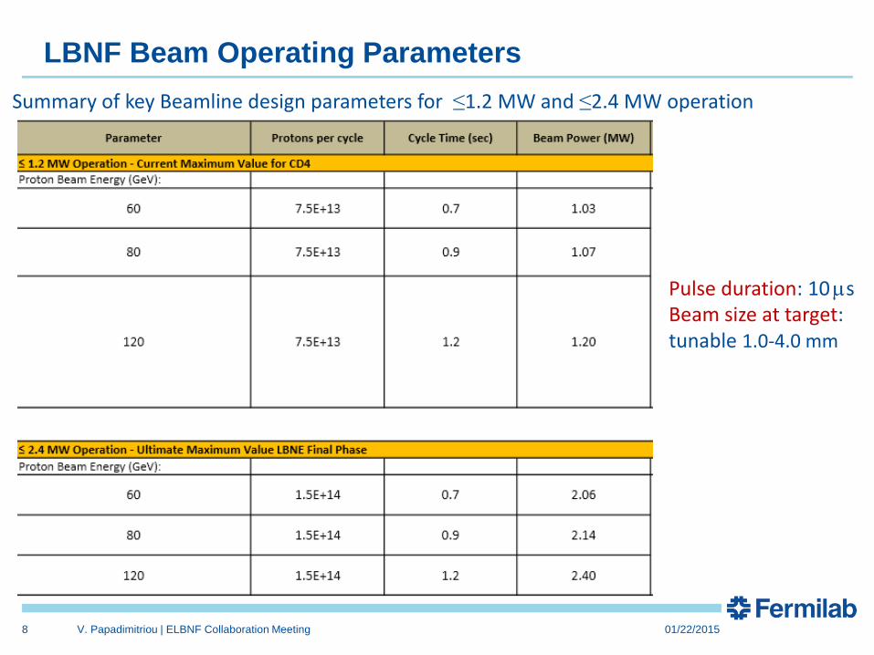
LBNF Beam Operating Parameters
8
Pulse duration: 10 ms Beam size at target: tunable 1.0-4.0 mm
Summary of key Beamline design parameters for ≤1.2 MW and ≤2.4 MW operation
V. Papadimitriou | ELBNF Collaboration Meeting 01/22/2015

What is being designed for 2.4 MW
9
• Designed for 2.4 MW, to allow for an upgrade in a cost efficient
manner:
– Primary beamline
– the radiological shielding of enclosures (primary beam enclosure,
the target shield pile and target hall except from the roof of the
target hall, the decay pipe shielding and the absorber hall) and
size of enclosures
– beam absorber
– decay pipe cooling and decay pipe downstream window
– remote handling
– radioactive water system piping (in penetrations)
V. Papadimitriou | ELBNF Collaboration Meeting 01/22/2015

15 Jan 2015 Jim Strait | Long-Baseline Neutrino Facility 10
• The LBNF Primary Beam will transport 60 - 120 GeV protons from MI-10 to the
LBNF target to create a neutrino beam. The beam lattice points to 79
conventional magnets (25 dipoles, 21 quadrupoles, 23 correctors, 6 kickers, 3
Lambertsons and 1 C magnet).
Primary Beam and Lattice Functions
Horizontal (solid) and vertical (dashed) lattice functions of the LBNF transfer line The final focus is tuned for x = y = 1.50 mm at 120 GeV/c with β* = 86.33 m and nominal MI beam
parameters ε99 = 30 μm & Δp99/p = 11x10-4
Beam size at target tunable between 1.0-4.0 mm
STRUCT/MARS simulations have shown that highest beam loss rate takes place right at the apex of the beamline
MI RR MI-10
Embankment
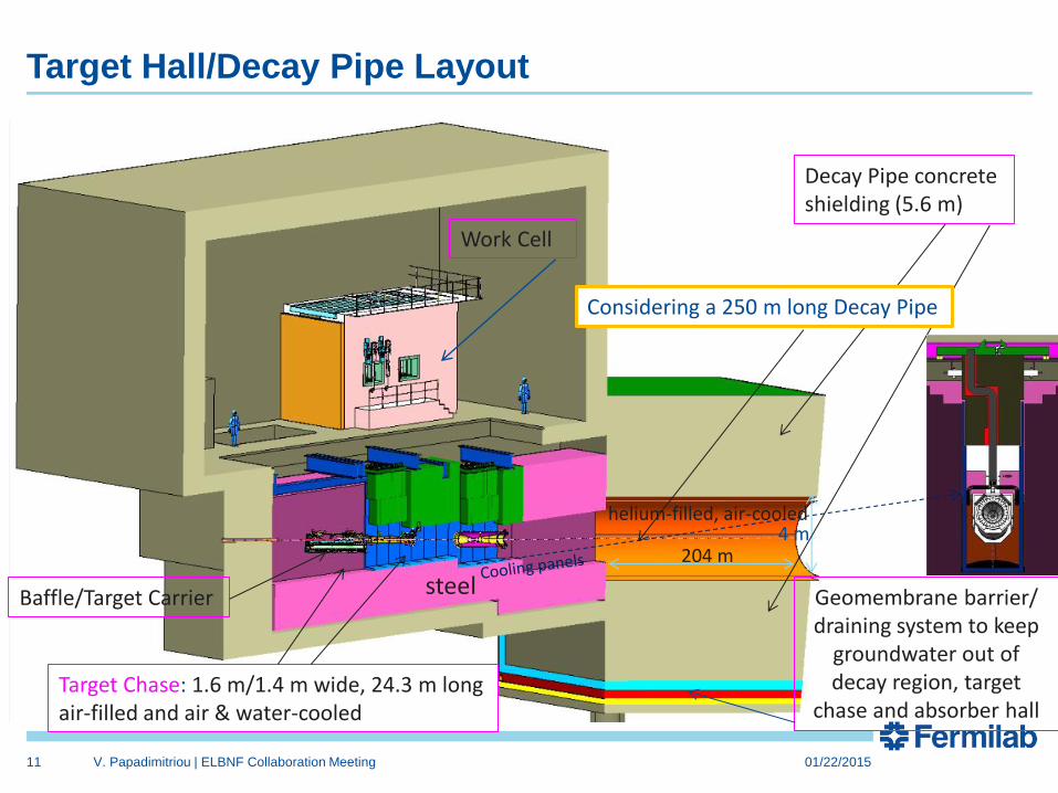
Target Hall/Decay Pipe Layout
11
Target Chase: 1.6 m/1.4 m wide, 24.3 m long air-filled and air & water-cooled
Decay Pipe concrete shielding (5.6 m)
Geomembrane barrier/ draining system to keep
groundwater out of decay region, target
chase and absorber hall
Work Cell
Baffle/Target Carrier
204 m 4 m
helium-filled, air-cooled
Considering a 250 m long Decay Pipe
steel
V. Papadimitriou | ELBNF Collaboration Meeting 01/22/2015

12
1.2 MW components inside the target chase
mm
47 graphite target segments, each 2 cm long Baffle
Target cross section
Horn
Horn Stripline
Beam size on target 1.7 mm (reducing stress)
200-230 KA

Decay pipe cooling air supply flows in four, 28” diam. pipes
and the annular gap is the return path (purple flow path)
The helium-filled decay pipe requires that a replaceable,
thin, metallic window be added on the upstream end of the
decay pipe
13
Concentric Decay Pipe. Both pipes are ½” thick carbon steel
Al (1m diam.) Be: 23.8 cm
diam.
Helium-filled/Air-cooled Decay Pipe
(Helium increases the n flux by ~10%)
32 clean cooling air pipes
4 - 28” cooling air supply pipes
Cooling air returns in the annular gap
13 V. Papadimitriou | ELBNF Collaboration Meeting

Current Configuration of Hadron Absorber
Side view of absorber core section here
Spoiler
Mask (5)
Sculpted Al (9)
Solid Al (4) Steel (4)
Beam
14
Sculpted Al block
Hadron Monitor (HM)
The Absorber is designed for 2.4 MW
• All core blocks replaceable
via remote handling
Remote Handling Facility for HM
concrete
Steel

Review Committee (Absorber Core Review)
• Curtis Baffes (CHAIR) – FNAL
• Chris Densham – RAL
• Ilias Efthymiopoulos – CERN
• Peter Kasper – FNAL
• Ang Lee – FNAL
• Antonio Marcone – CERN
• Andy Stefanik – FNAL
15 01/22/2015
January 20-22, 2015 Just had closeout
Very successful – “clear pass”
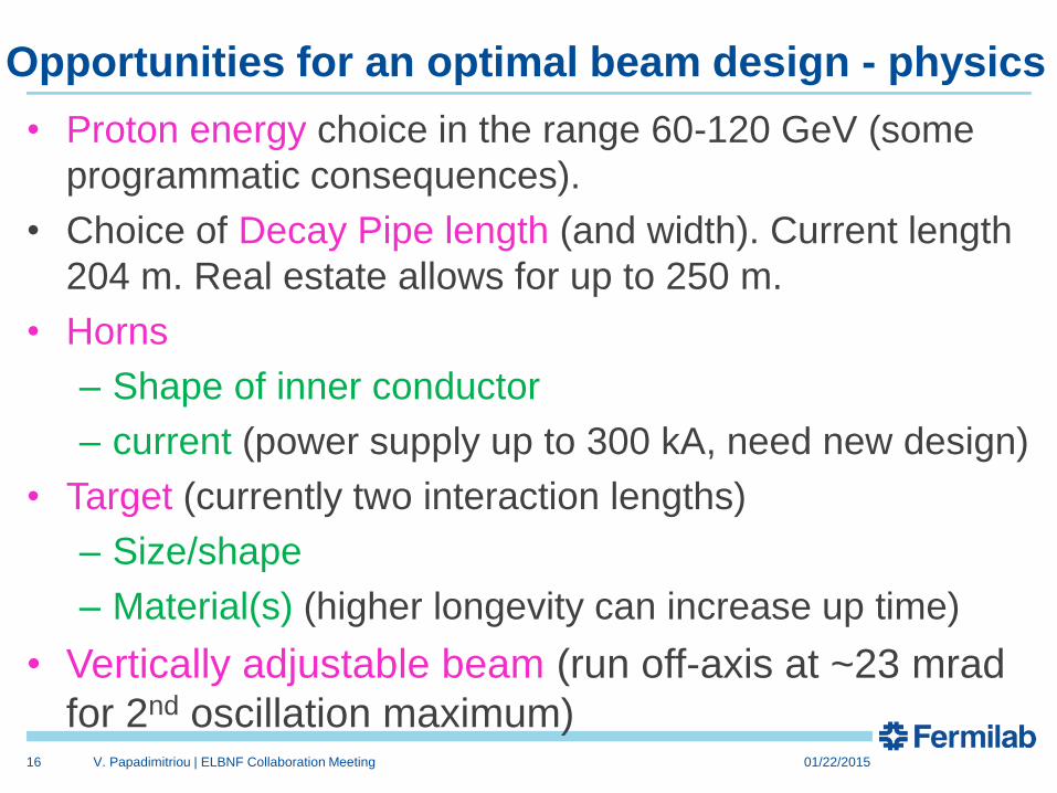
Opportunities for an optimal beam design - physics
• Proton energy choice in the range 60-120 GeV (some
programmatic consequences).
• Choice of Decay Pipe length (and width). Current length
204 m. Real estate allows for up to 250 m.
• Horns
– Shape of inner conductor
– current (power supply up to 300 kA, need new design)
• Target (currently two interaction lengths)
– Size/shape
– Material(s) (higher longevity can increase up time)
• Vertically adjustable beam (run off-axis at ~23 mrad
for 2nd oscillation maximum)
16 V. Papadimitriou | ELBNF Collaboration Meeting 01/22/2015

Possible improvements in the focusing system
• When LBNE was reconfigured in 2012, in order to save money we
abandoned our LBNE optimized target and horn designs and opted for
NuMI designs with small modifications. (e.g.we were able to verify the
NuMI horns up to 230 kA instead of their 200 kA design value).
LBNE Sept.
2012
LBNE March
2012
Beam Power 708 kW 708 kW
Horn 1 shape Double
Parabolic
Cylindrical/Parabolic
Horn current 200 kA 300 kA
Target Modified
MINOS (fins)
IHEP cylindrical
Target “Carrier” NuMI-style
baffle/ target
carrier
New handler, target
attaches to Horn 1
CD-1
Tunable En spectrum
LBNE CD-1 – NuMI like horn 1 LBNE prereconfiguration horn 1
17
Horn 1 simulation using LBNO’s opt. method
A. Bashyal
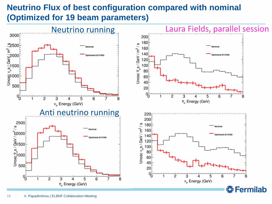
Neutrino Flux of best configuration compared with nominal
(Optimized for 19 beam parameters)
18
Laura Fields, parallel session
V. Papadimitriou | ELBNF Collaboration Meeting
Neutrino running
Anti neutrino running
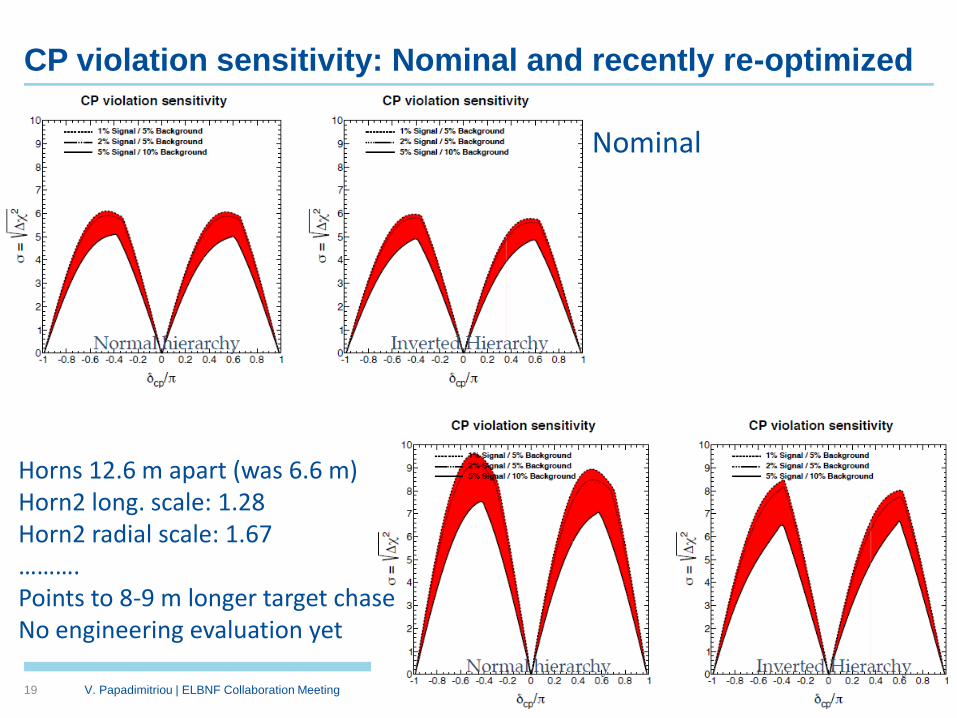
CP violation sensitivity: Nominal and recently re-optimized
19 V. Papadimitriou | ELBNF Collaboration Meeting 01/22/2015
Horns 12.6 m apart (was 6.6 m) Horn2 long. scale: 1.28 Horn2 radial scale: 1.67 ………. Points to 8-9 m longer target chase No engineering evaluation yet
Nominal
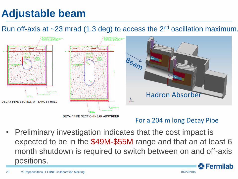
Adjustable beam
20 V. Papadimitriou | ELBNF Collaboration Meeting 01/22/2015
• Preliminary investigation indicates that the cost impact is
expected to be in the $49M-$55M range and that an at least 6
month shutdown is required to switch between on and off-axis
positions.
Hadron Absorber
Run off-axis at ~23 mrad (1.3 deg) to access the 2nd oscillation maximum.
For a 204 m long Decay Pipe

Novel Target Designs
• High heat-flux coolants
– Elimination of water
• Composite targets
• Segmentation
• Robust materials and assemblies
21 V. Papadimitriou | ELBNF Collaboration Meeting
Advanced conceptual design of the Beamline available for
1.2 MW operation using NuMI-like target and horns
Several opportunities available to further optimize the
beam design
Before CD-1 we had an engineering evaluation of a more
optimized horn but had to abandon that work in order to
reduce cost. We are now at the early simulation stage –
using the LBNO approach - of evaluating more optimal for
the physics target/horn designs but no significant
engineering has been done for those.
We have early indications that we will need to increase the
size (especially the length) of the target chase to fit those.
As far as we have a target chase of sufficient size we can
always switch to more optimized components later.
Summary/Conclusions
22 V. Papadimitriou | ELBNF Collaboration Meeting

Near Site Schedule: Beamline and Near Detector Cavern
23
Work is technically-limited starting Oct 2015
V. Papadimitriou | ELBNF Collaboration Meeting

Range: lower to upper bound
Target: (2 * lower + upper)/3
NuMI (e20) BNB (e20) g-2 (e20)
FY16 Range 4.2 – 6.0 1.4 – 2.1 0
FY16 Target 4.8 1.7
FY17 Range 4.7 – 6.8 2.7 – 3.9 0.72 – 0.85
FY17 Target 5.4 3.1 0.76
POT Projections: FY16 & FY17
1/22/2015 24 V. Papadimitriou | ELBNF Collaboration Meeting
Do we need 700 kW prior to 2024 pointing to SURF?
• It would be very useful to start data taking with beam as soon as possible to commission beamline and detectors and start understanding the data. In that respect it would be great to start data taking with 700 kW on the target and continue with 1.2 MW as soon as it is available.
• NOvA expects to run 6 years at 700 kW and accumulate 6x10²⁰ POT per year for a total of 3.6x10²¹ POT.
• The expectation is to reach 700 kW within FY16 and taking into account the current operational scenario NOvA will reach its goal by the end of FY2021.
• A ~13 month long shutdown is needed to connect the LBNF Beamline with MI. In the mean time a ~ 8 month shutdown is needed to connect the PIP-II injector with the Booster and it would be helpful to have them take place at the same time.
25 V. Papadimitriou | ELBNF Collaboration Meeting

Do we need 700 kW prior to 2024 pointing to SURF?
• If the long shutdown takes place after NOvA data taking is complete it means that it will take the entire FY22 and part of FY23.
• After the Beamline has beneficial occupancy it requires about 2 years of installation in a technically driven schedule implying that the Beamline will not be ready to take data before FY25.
• PIP-II is expected to deliver 1.2 MW in ~2024, so this does not allow any time for 700 kW data taking for LBNF unless we find ways to speed up the installation time.
• On the other hand, if the shutdown takes place before FY22, it could speed up the possibility to start as soon as possible data taking with 1.2 MW and can maximize 700 kW data taking for NOvA.
• That would imply though a gap in data taking for NOvA, would not allow for LBNF Beamline to use NOvA components and would imply sufficient resources to have both PIP-II and LBNF to be ready for a shutdown before FY22.
26 V. Papadimitriou | ELBNF Collaboration Meeting
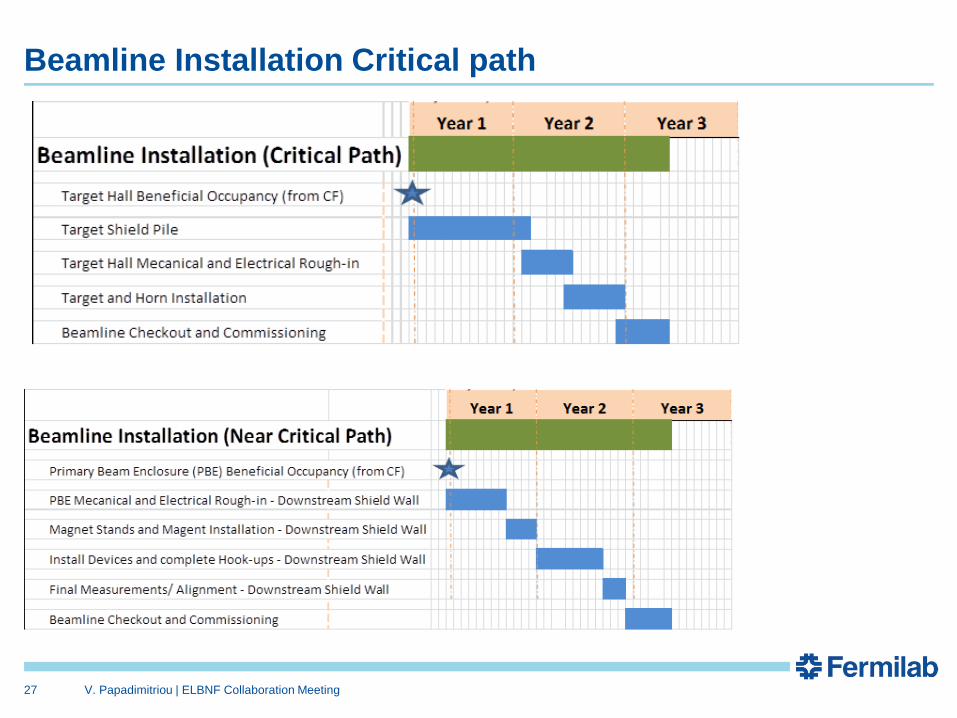
Beamline Installation Critical path
27
V. Papadimitriou | ELBNF Collaboration Meeting

Supplemental Material
28

Current Status of High Power Target R&D Activities
• Although focus on the High Power Targetry R&D Program is
relatively recent, good progress has already been made
– RaDIATE collaboration (possibility for an additional
irradiation run at BNL’s BLIP facility in 2016)
– HiRadMat (In-beam thermal shock test) experiment (Beam
time at CERN in November 2015)
– Fatigue testing machine (hot-cell compatible) design
– Simulation (Monte-Carlos, Thermo-mechanical) efforts to
support above activities
– Autopsy of NuMI graphite targets
29 V. Papadimitriou | ELBNF Collaboration Meeting

Recent Accelerator Complex reconfiguration
With the conclusion of the Tevatron program, the Recycler can be used to pre-
inject to MI and stack the Booster protons, thus saving injection time
A 15 month shutdown to reconfigure the accelerator complex and to upgrade the
NuMI beamline was completed in August 2013.
The upgrades will allow 700 kW on the NuMI target
MI tunnel
Main Injector
NuMI line
Recycler
Recycle
r M
ain
In
jecto
r
12 Booster batches injected and slipped stacked in RR while MI is accelerating

The Fermilab Accelerator Complex Today
• The Fermilab complex delivers protons for neutrino production at both 8 and 120 GeV, with a capability following PIP completion:
– Booster: 4.2×10¹² protons @ 8 GeV @ 15 Hz = 80 kW
– MI: 4.9×10¹³ protons @ 120 GeV @ 0.75 Hz = 700 kW
• Present limitations
– Booster pulses per second
• The Booster magnet/power supply system operates at 15 Hz
• PIP is upgrading the RF system to 15 Hz
– Booster protons per pulse
• Limited by space-charge forces at
Booster injection
– Reliability
• Linac/Booster represent a non-negligible operational risk
– Target systems capacity
• Limited to ~700 kW by a large number of factors
31
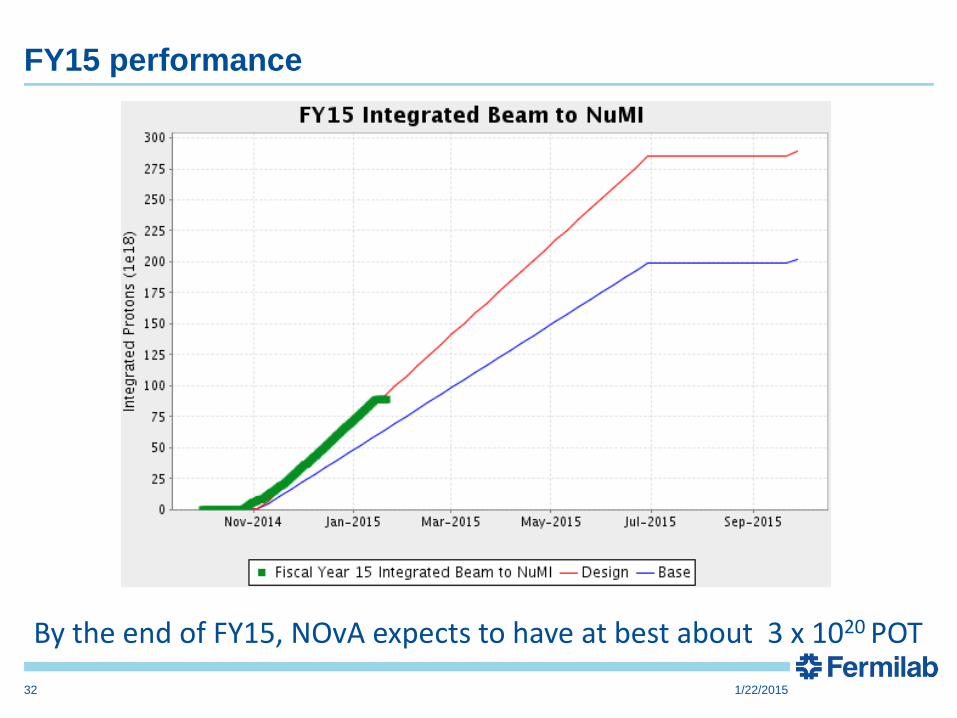
FY15 performance
1/22/2015 32
By the end of FY15, NOvA expects to have at best about 3 x 10²⁰ POT

1/22/2015 33
Accelerator Performance for NuMI • Started delivering protons to NuMI in 2005
– ~1.55e21 in 7 years; NOvA goal is 3.6e21
– Most intense high energy neutrino beam in the world
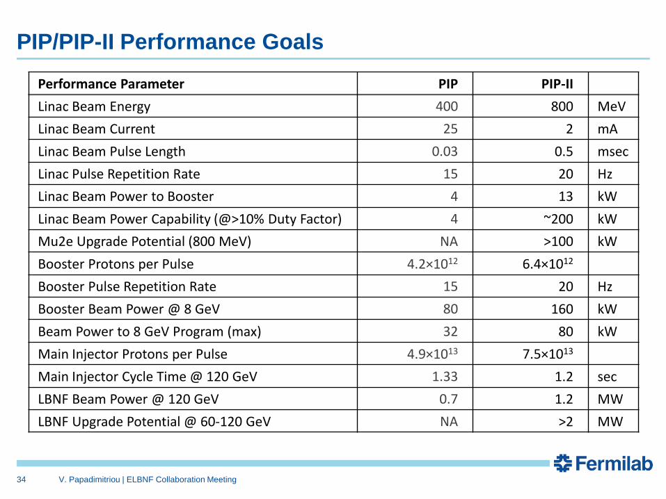
PIP/PIP-II Performance Goals
Performance Parameter PIP PIP-II
Linac Beam Energy 400 800 MeV
Linac Beam Current 25 2 mA
Linac Beam Pulse Length 0.03 0.5 msec
Linac Pulse Repetition Rate 15 20 Hz
Linac Beam Power to Booster 4 13 kW
Linac Beam Power Capability (@>10% Duty Factor) 4 ~200 kW
Mu2e Upgrade Potential (800 MeV) NA >100 kW
Booster Protons per Pulse 4.2×10¹² 6.4×10¹²
Booster Pulse Repetition Rate 15 20 Hz
Booster Beam Power @ 8 GeV 80 160 kW
Beam Power to 8 GeV Program (max) 32 80 kW
Main Injector Protons per Pulse 4.9×10¹³ 7.5×10¹³
Main Injector Cycle Time @ 120 GeV 1.33 1.2 sec
LBNF Beam Power @ 120 GeV 0.7 1.2 MW
LBNF Upgrade Potential @ 60-120 GeV NA >2 MW
34
V. Papadimitriou | ELBNF Collaboration Meeting

Future Directions
• The strategy for next step(s) beyond PIP-II will be developed in consideration of the following: – Slip-stacking in the Recycler is not possible at intensities beyond PIP-II
– The Booster cannot be upgraded to support intensities beyond ~7×10¹² ppp, no matter what the injection energy
– A new 8-GeV rapid cycling synchrotron (RCS) could meet the needs of the neutrino program
• Beam power @ 8 GeV ~600kW
• Injection energy ~2 GeV
– Construction of an RCS would require long-term utilization of the Recycler for proton accumulation
– An extension of the PIP-II linac to 6-8 GeV would be required to remove the Recycler from service and/or to achieve the 1-4 MW required to support a muon-based facility
• The strategy will likely be determined on the basis of programmatic choices once PIP-II construction is underway
• In all scenarios it will be necessary to extend the PIP-II linac to at least 2 GeV and to retire the existing Booster
– Unless realization of “smart RCS” with lower (800 MeV) injection energy
35

Major Components of the Neutrino Beam
36
Primary Beam Window
Target
Tunable neutrino energy spectrum
For now, NuMI-like low energy target (two interaction lengths) & NuMI design horns with some needed modifications for 1.2 MW operation
The neutrino spectrum is determined by the geometry of the target, the focusing horns and the decay pipe geometry
01/22/2015 V. Papadimitriou | ELBNF Collaboration Meeting
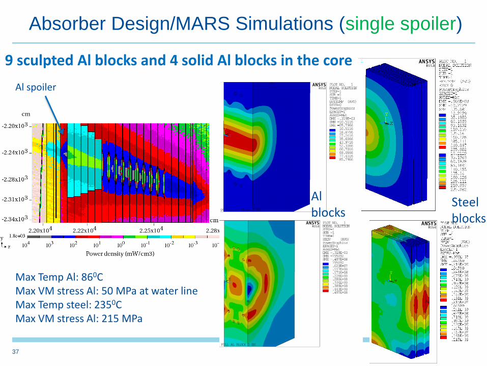
Absorber Design/MARS Simulations (single spoiler)
37
9 sculpted Al blocks and 4 solid Al blocks in the core
Max Temp Al: 860C Max VM stress Al: 50 MPa at water line Max Temp steel: 2350C Max VM stress Al: 215 MPa
Steel blocks
Al blocks
37
Al spoiler
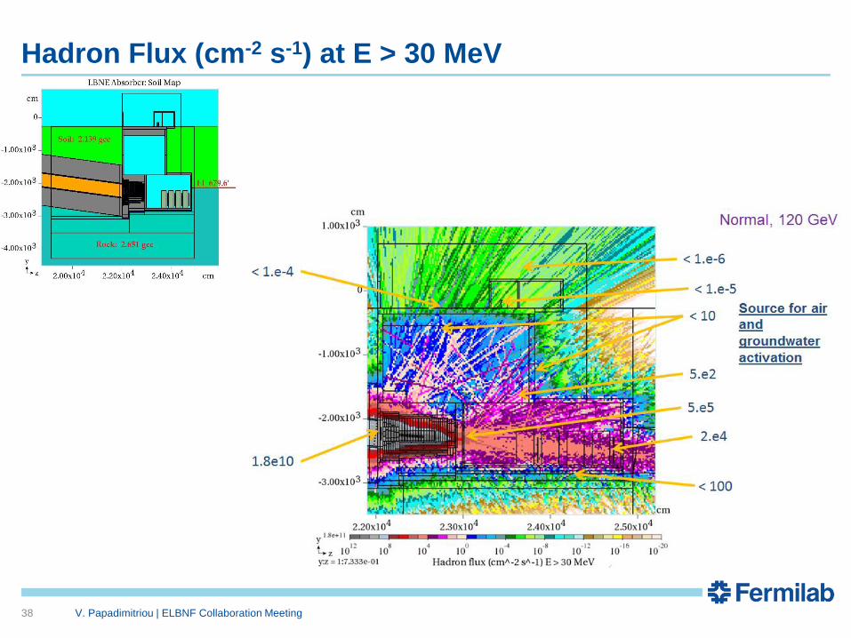
Hadron Flux (cm-2 s-1) at E > 30 MeV
38 V. Papadimitriou | ELBNF Collaboration Meeting
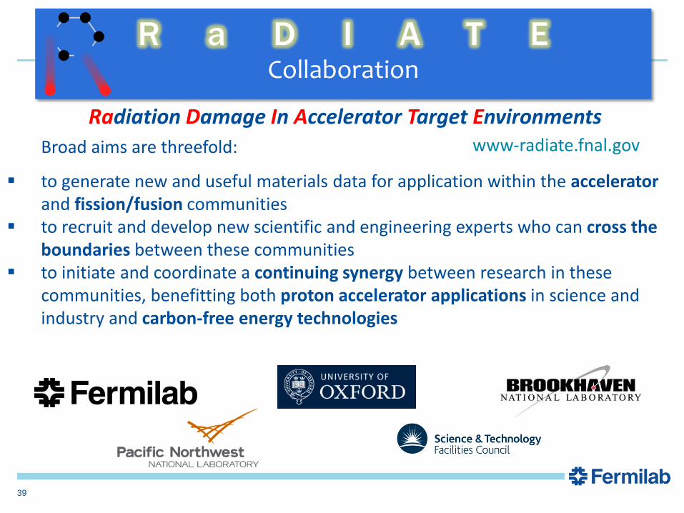
Radiation Damage In Accelerator Target Environments
R a D I A T E Collaboration
Broad aims are threefold:
to generate new and useful materials data for application within the accelerator and fission/fusion communities
to recruit and develop new scientific and engineering experts who can cross the boundaries between these communities
to initiate and coordinate a continuing synergy between research in these communities, benefitting both proton accelerator applications in science and industry and carbon-free energy technologies
www-radiate.fnal.gov
39
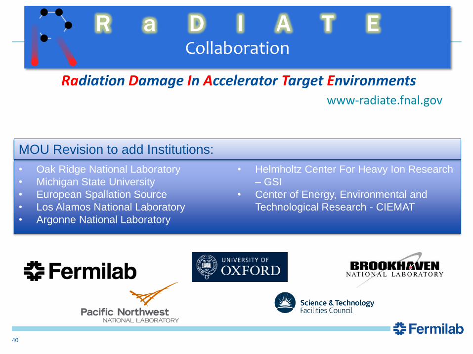
Radiation Damage In Accelerator Target Environments
R a D I A T E Collaboration
www-radiate.fnal.gov
• Oak Ridge National Laboratory
• Michigan State University
• European Spallation Source
• Los Alamos National Laboratory
• Argonne National Laboratory
• Helmholtz Center For Heavy Ion Research
– GSI
• Center of Energy, Environmental and
Technological Research - CIEMAT
MOU Revision to add Institutions:
40

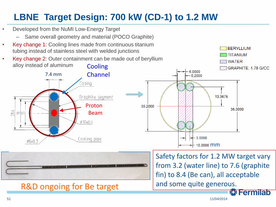
Initial Modifications for 1.2 MW
• Wider target material (still graphite): 7.4 10.0 mm
• Dual cooling pipes – greater surface area
• Slightly larger outer vessel diameter: 30 36 mm
(Move target back 10 cm from horn)
47 graphite segments, each 2 cm long
41
7.4 mm 700 kW design (CD-1)
cm
mm
Proton Beam

Preliminary target design for 1.2 MW
Target critical safety factors
• Target evolved from NuMI
– Target/horn system efficiency somewhat compromised from optimal – mostly horns
• Expect to change graphite target ~2-3 a year for 1.2 MW operation
– Limited lifetime due to radiation damage of graphite
• Based on limited in-beam experience
• Option remains for Be as target material pending validation.
42
No showstoppers identified at this point
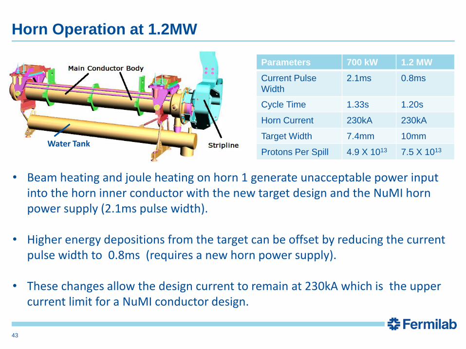
Horn Operation at 1.2MW
Parameters 700 kW 1.2 MW
Current Pulse
Width
2.1ms 0.8ms
Cycle Time 1.33s 1.20s
Horn Current 230kA 230kA
Target Width 7.4mm 10mm
Protons Per Spill 4.9 X 10¹³ 7.5 X 10¹³
• Beam heating and joule heating on horn 1 generate unacceptable power input into the horn inner conductor with the new target design and the NuMI horn power supply (2.1ms pulse width).
• Higher energy depositions from the target can be offset by reducing the current
pulse width to 0.8ms (requires a new horn power supply).
• These changes allow the design current to remain at 230kA which is the upper current limit for a NuMI conductor design.
Water Tank
43
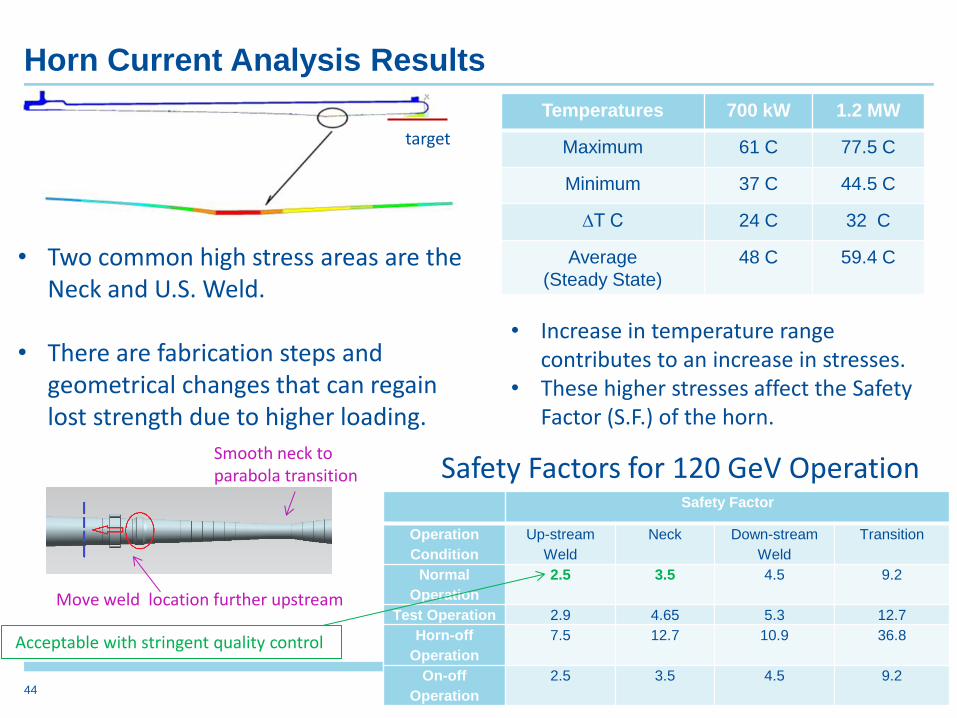
Horn Current Analysis Results
Temperatures 700 kW 1.2 MW
Maximum 61 C 77.5 C
Minimum 37 C 44.5 C
∆T C 24 C 32 C
Average
(Steady State)
48 C 59.4 C
• Increase in temperature range contributes to an increase in stresses.
• These higher stresses affect the Safety Factor (S.F.) of the horn.
• Two common high stress areas are the Neck and U.S. Weld.
• There are fabrication steps and
geometrical changes that can regain lost strength due to higher loading.
Move weld location further upstream
Smooth neck to parabola transition
target
10/15/2014 44
Safety Factor
Operation
Condition
Up-stream
Weld
Neck Down-stream
Weld
Transition
Normal
Operation
2.5 3.5 4.5 9.2
Test Operation 2.9 4.65 5.3 12.7
Horn-off
Operation
7.5 12.7 10.9 36.8
On-off
Operation
2.5 3.5 4.5 9.2
Safety Factors for 120 GeV Operation
Acceptable with stringent quality control
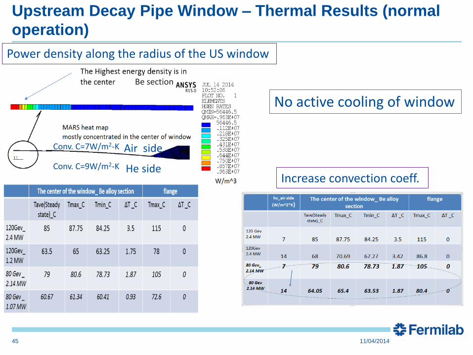
Upstream Decay Pipe Window – Thermal Results (normal
operation)
45
Power density along the radius of the US window
Be section
He side
Air side
Conv. C=9W/m2-K
Conv. C=7W/m2-K
Increase convection coeff.
No active cooling of window
11/04/2014

The Beamline Team so far and collaborative activities
• From Fermilab’s Accelerator, Particle Physics and Technical Divisions, FESS (Facil. Eng.) and ES&H Sections.
• University of Texas at Arlington (Hadron Monitor)
• STFC/RAL (target R&D and target design)
• Bartoszek Eng. (Contract on baffle/target and horn support modules)
• RADIATE Collaboration (radiation damage for target and windows)
• CERN (target R&D, corrosion, Beamline monitoring,…)
• US-Japan Task force (radiation damage, non-interactive profile monitor, kicker magnets)
• IHEP/China (simulations, beam window, special alloys)
• Six contracts completed already with ANL, BNL, IHEP (Protvino, Russia), STFC/RAL, ORNL, Design Innovations.
46

Adjustable beam • We considered both horizontal and vertical steering options.
• Most promising: Vertical steering of beam pivoting around the
target.
• Two discrete positions for on- and off-axis – will require
reconfiguration of beamline (with a significant shutdown of at
least 6 months) to switch between on-axis and off-axis.
• Run off-axis at ~23 mrad (1.3 deg) to access the 2nd
oscillation maximum.
• Near Detector does not move from default position & sees the
same off-axis beam as the Far Detector.
• Complete optics design has been fleshed out.
• Gradually increasing vertical cross section of the decay pipe
(9.4 m at the end of the 204 m pipe) and significantly bigger
absorber (we considered two staggered absorbers).
47 V. Papadimitriou | ELBNF Collaboration Meeting 01/22/2015

Upstream Decay Pipe Window – Stresses (Accident Case)
48
Air side: p=1.5 psi; Conv. Coeff.= 7 W/m2-K
The window will not be able to survive the accident condition under a 2.14 or 2.4 MW beam power but it can survive a few accident pulses at 1.2 MW.
15 Jan 2015 49
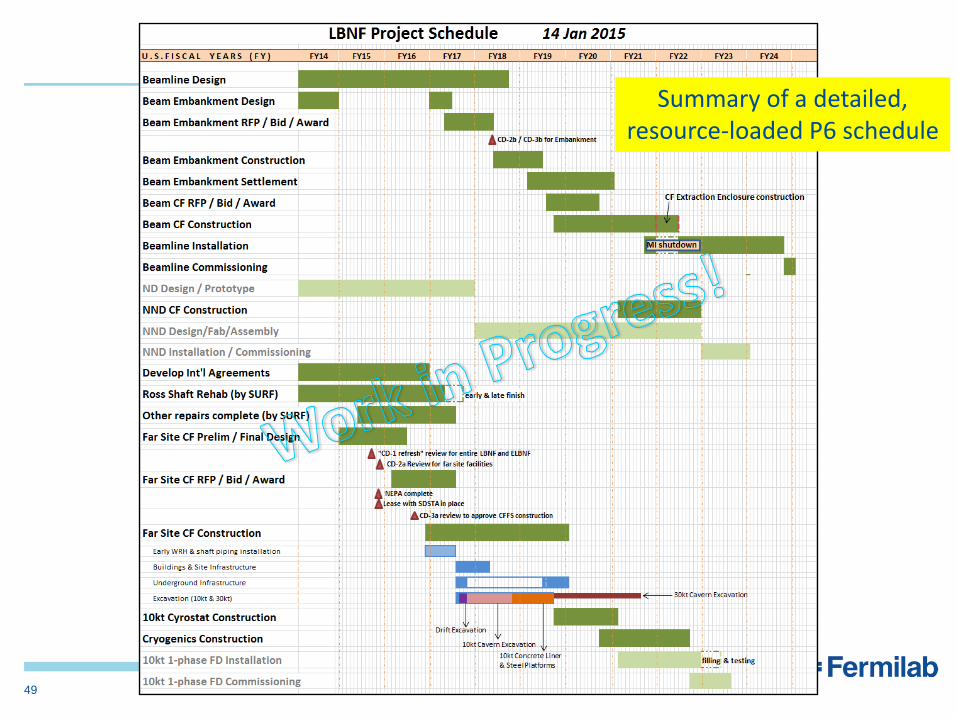
Summary of a detailed, resource-loaded P6 schedule

Mass Hierarchy and CP Violation Sensitivity
50
Exposure 245 kt.MW.yr
34 kt x 1.2 MW x (3n+3nbar) yr
Mass hierarchy is very well determined over most of dCP range
CPV > 3 over most of range and > 5 for maximal CPV
Atmospheric neutrinos in LBNE provide ~1 increased CPV sensitivity if
combined with beam
Band is range of beam and
systematics assumptions
Unoptimized beam
& poor systematics
Optimized beam
& systematics goal
51
mm
LBNE Target Design: 700 kW (CD-1) to 1.2 MW
Proton Beam
Cooling Channel
• Developed from the NuMI Low-Energy Target
– Same overall geometry and material (POCO Graphite)
• Key change 1: Cooling lines made from continuous titanium
tubing instead of stainless steel with welded junctions
• Key change 2: Outer containment can be made out of beryllium
alloy instead of aluminum
7.4 mm
Safety factors for 1.2 MW target vary from 3.2 (water line) to 7.6 (graphite fin) to 8.4 (Be can), all acceptable and some quite generous. R&D ongoing for Be target
11/04/2014
“BeGrid” High Intensity Beam Pulse Test
• Proton beam capabilities:
– up to 4.9e13 ppp
– 440 GeV
– 0.1 mm – 2.0 mm sigma radius
• Test on Be samples to detect:
– Onset of plastic deformation (LDV, SG)
– Fracture (EBSD)
– Micro-structural damage mechanisms (EBSD)
– Differences between grades and forms (texture) of Beryllium
• Verify simulations HRMT-14 Collimator materials test rig (image courtesy of A. Fabich, CERN)
52 11/04/2014
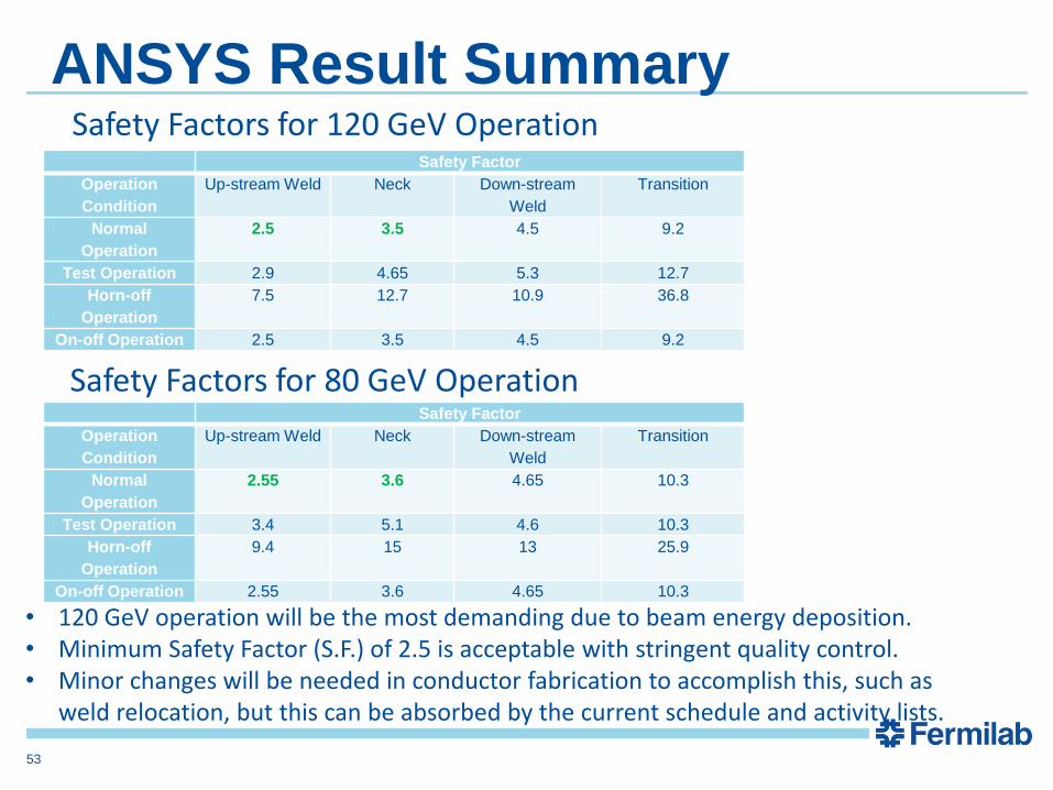
ANSYS Result Summary
Safety Factor
Operation
Condition
Up-stream Weld Neck Down-stream
Weld
Transition
Normal
Operation
2.55 3.6 4.65 10.3
Test Operation 3.4 5.1 4.6 10.3
Horn-off
Operation
9.4 15 13 25.9
On-off Operation 2.55 3.6 4.65 10.3
Safety Factor
Operation
Condition
Up-stream Weld Neck Down-stream
Weld
Transition
Normal
Operation
2.5 3.5 4.5 9.2
Test Operation 2.9 4.65 5.3 12.7
Horn-off
Operation
7.5 12.7 10.9 36.8
On-off Operation 2.5 3.5 4.5 9.2
Safety Factors for 80 GeV Operation
Safety Factors for 120 GeV Operation
• 120 GeV operation will be the most demanding due to beam energy deposition. • Minimum Safety Factor (S.F.) of 2.5 is acceptable with stringent quality control. • Minor changes will be needed in conductor fabrication to accomplish this, such as
weld relocation, but this can be absorbed by the current schedule and activity lists.
53
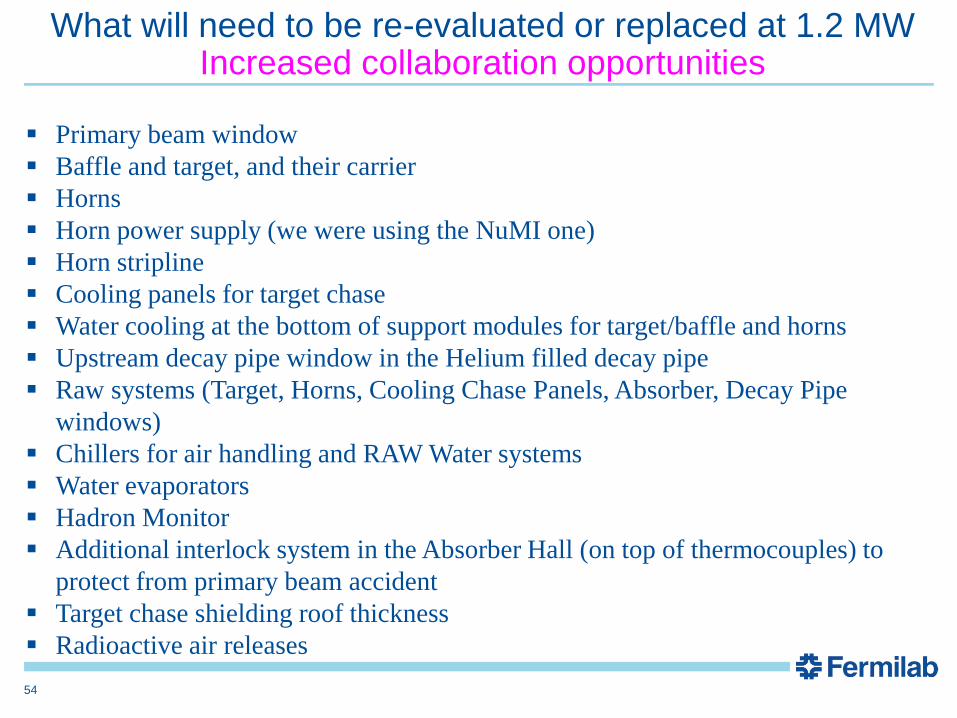
Primary beam window
Baffle and target, and their carrier
Horns
Horn power supply (we were using the NuMI one)
Horn stripline
Cooling panels for target chase
Water cooling at the bottom of support modules for target/baffle and horns
Upstream decay pipe window in the Helium filled decay pipe
Raw systems (Target, Horns, Cooling Chase Panels, Absorber, Decay Pipe
windows)
Chillers for air handling and RAW Water systems
Water evaporators
Hadron Monitor
Additional interlock system in the Absorber Hall (on top of thermocouples) to
protect from primary beam accident
Target chase shielding roof thickness
Radioactive air releases
What will need to be re-evaluated or replaced at 1.2 MW Increased collaboration opportunities
54

LBNE Beam Tunes: Moving the target with respect to Horn 1
55
Move target 1.5 m upstream of Horn 1
Move target 2.5 m upstream of Horn 1

Considered design changes that increase the physics
potential
56
Change 0.5-2.0
GeV
2.0-5.0
GeV
Impact
DK pipe Air He 1.07 1.11 ~$ 9 M
DK pipe length 200 m 250 m (4m D) 1.04 1.12 ~$ 30 M
DK pipe diameter 4 m 6 m (200m L) 1.06 1.02 ~ $17 M
Horn current 200 kA 230 kA 1.00 1.12 small
Proton beam 120 80 GeV, 700 kW 1.14 1.05 Programmatic
impact
Target graphite fins Be fins 1.03 1.02 Increase
target lifetime
Total 1.39 1.52
If both $55 M
Ratio of nmne CC appearance rates at the far detector
Subject of R&D
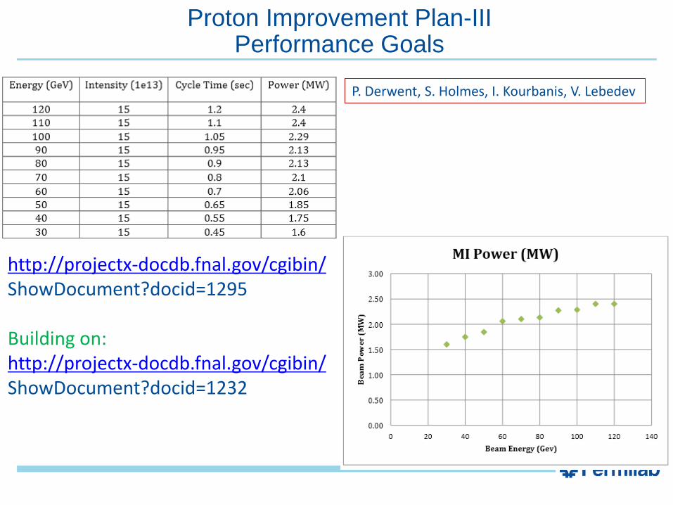
Proton Improvement Plan-III Performance Goals
http://projectx-docdb.fnal.gov/cgibin/ ShowDocument?docid=1295 Building on: http://projectx-docdb.fnal.gov/cgibin/ ShowDocument?docid=1232
P. Derwent, S. Holmes, I. Kourbanis, V. Lebedev
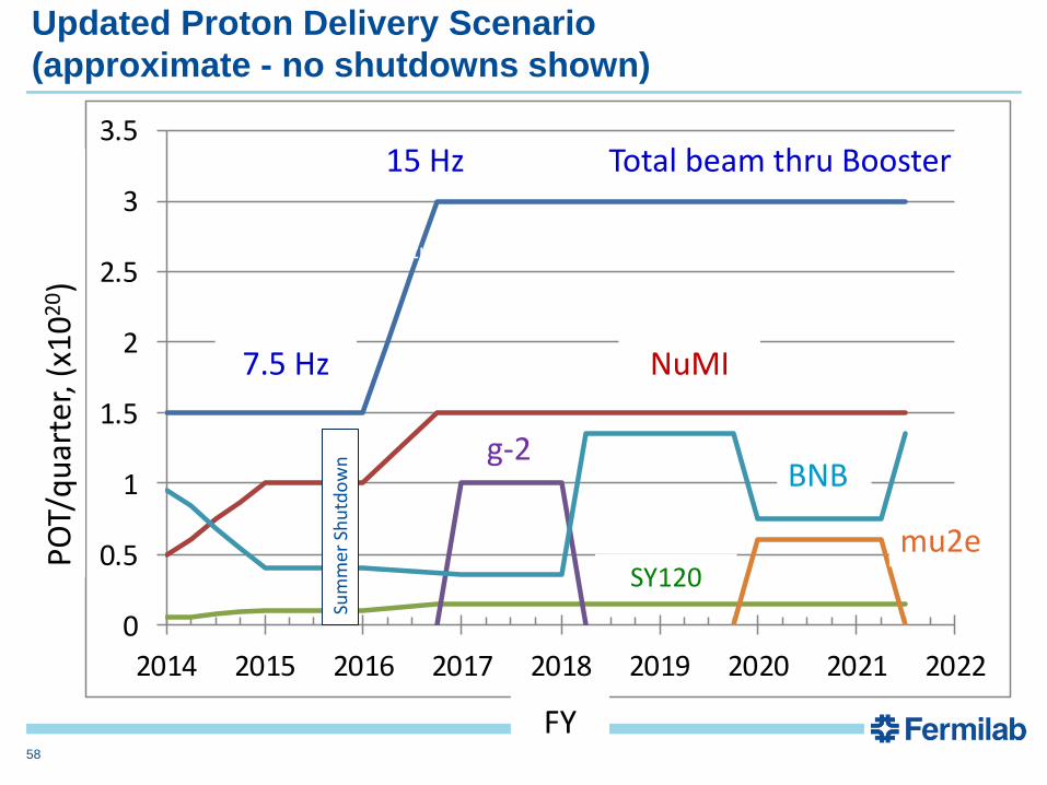
0
0.5
1
1.5
2
2.5
3
3.5
2014 2015 2016 2017 2018 2019 2020 2021 2022
PO
T/q
uar
ter,
(x1
02
0)
FY
7.5 Hz
15 Hz
NuMI
BNB
mu2e
g-2
SY120
Total beam thru Booster
Sum
mer
Sh
utd
ow
n
Ramp up flux – tuning/loses
Updated Proton Delivery Scenario
(approximate - no shutdowns shown)
58