opidtic · (1, 2, or 3). antennas 1 and 2 dre located in the same •* transverse plane. each...
TRANSCRIPT

I: ~~~~~REPR61k&f AT GOA%*4MkI EPJ
COM'PONENT PART NOTICE
THIS PAPER IS A C(MPONENT PART OF THE FO.LOWING COWPILATION REPORT:
TITLE: Proceedings of the An~tana Applicationa S oai=um Held at Urbana.
9* J..1jflllnpi nrn 19.21 Saqtaoaher 19A&. Vnluma 2.
To ORDER THE COMPLETE COMPILATION REPORT, USE AD-A153 258
THE COMPONENT PART IS PROVIDED HERE TO ALLOW USERS ACCESS TO INDIVIDUALLY
"AUTHORED SECTIONS OF PROCEEDING, ANNALS, SYMPOSIA, ETC. HOkEVER, 7HE CCONENTSHOULD BE CONSIDERED WITHIN THE CONTEXT OF THE OVERALL C21PILATION REPORT AND
NOT AS A STAND-ALONE TECHNICAL REPORr.
THE FOLLOWING COM~PONENT PART NUMBERS COMPRISE THE CMPILATION REPORT:
AD)#: AD-P004 620 thru AN.: AD-PM& 637
___________~AW:______""AD#: AM:-
D 5 OPIDTIC
4saudwws bow beesCr.>.J~imPubcowa" 0 samd
-I -
DTIC Fi .. OPI: DTIC-TID"MAAR 85~ lr

'I,.
* .1
EXTENSION OF PLANE-WAVE SCATTERING-MATRIX THEORYOF ANTENNA - ANTENNA INTERACTIONS TO THREE ANTENNAS:
A NEAR-FIELD RADAR CROSS SECTION CONCEPTC0.,* Michael A. Dinallo
The BDM Corporation1801 Randolph Road, S.E.
Albuquerque, New Mexico 87106
Abstract
This paper presents a three-antenna plane-wave scattering-
* matrix (PWSM) formulation and a formal solution. An example will
be demonstrated in which two of the three antennas are electro-
magnetically identical (the transmitter and receiver) and the
third (the scatterer) has arbitrary electromagnetic properties.
A reduced reflection integral-matrix will be discussed which
describes the transmit, scatter, receive (TSR) interaction. An
antenna scatterer spectral tensor Greens function is identified.
In this formulation the transmit spectrum will be scattered by
the third arbitrary antenna (target) and this scattered spectrumS[...
may be considered to have originated from a transmitting antenna. TI
Near-field antenna mieasurement techniques are applicable which
"determine the electric (scattered) field spectral density
If a second deconvolution is applied, a transmit
"probe corrected spectral density function or scattering tensor
can be determined in orinciple. In either case, a near- or far-
electric field can be calculated and a radar cross section
determined. / ,.
665/ . ' . * † † I,-. ******I

2. Introduction *1
The successful results that near-field antenna measurement
techniques have achieved in determining far-field antenna
patterns encourage the idea that perhaps similar techniques may
be applied to determine a target's far-field radar cross-section
'RCS) based upon near- scattered field measurements. The idea
K that a target's far-field RCS can be determined from near-
scattered field measurements is considered here as a near-field
RCS concept. Planar scanning near-field antenna measurement is
theoretically substantiated using the two-antenna, plane-wave r;
scattering-matrix (PWSM) formulation. 2 Since determining an RCS
requires a transmit probe, a target, and a receive probe,
extending the PWSM formulation to include three antennas was
chosen for investigating the feasibility of a near-field RCS
concept. This paper presents a three-antenna PWSM formulation,
discusses some of the results, and shows how this formulation -,
substantiates the near-field RCS concept.
In the following section, the theory and definitions asso-
ciated with the PWSM fomulation are stated. 2 This is followed by
a section on the three-antenna PWSM equations and a general
solution. A specific solution for the RCS problem (TSR inter-
action) is then presented in section 5. The paper closes by
stating conclusions and identifying future efforts related to
this topic.
666
*6•A _ _ rA Z

3. Background
The PWSM formulation of antennas depends upon the plane-wave
"representation of an electromagnetic field. Beginning with
plane-wave solutions to Maxwell's equations in a rectangular xyz
coordinate system in free space, solutions for E and H can .be
constructed from elementary plane-waves. Referring to figure 1,
an antenna system bounded by two planar surfaces F, and F2, which
are transverse to the z-axis direction (e ,can have correspond-' (ez
ing E and H field solutions in the form of weighed-sums of plane-
waves traveling to the right and left on either side of the
antenna. Specifically,
r 1 .
E, t a) b (,+ MK)di (1-a)
1 f bI ([mK)e"lYl - a,(rK)e nX ^1m nl (R)e'R dR (1-b)!qt r, 2w q q M M
where the following sign conventions and definitions apply: q
takes on values of 1 or 2 which correspond to the right (Fl) or
*- left (F2 ) side of the antenna, respectively; also, q values of 1S.w
or 2 dictate use of the upper or lower sign respectively, found
with the z-dependent exponentials; the subscript t denotes the
transverse components (w.r.t. e'); m takes on values of 1 and 2
which correspond to TM and TE polarizations respectively; the
transverse vectors K and R and the transverse unit vector icm and
y are defined in (1-c); n is the unit outward normal to F
q q
667

AI
.41
A '4-
* 9 I
"*, I
,-. - -"-- Ni
S• .
• 4'-
6%•
-. ,
668

!rnm(K) are the TM and TE wave admittences; b (m,K) and a (mK)
are the continuous spectral (angular) density functions for
eftrgent and Incident (relative to ard Fq) plane-waves,
respectively. Finflly, an e1tw' time dependence is used.
"R X k, - a +y~acX a n -
X yy Y I x Y y
* •: t (1-C)
.4 C 0 0
The remaining component of E and He~z) can be obtained by using Vthe fact '.hat each elementary plane-wave is orthogonal to k,
i.e., k.E(or H) -0. Thit is referred to as transversality in C
refe! er.ce 1.
Expressions for b (m,K) and a (m,K) are obtained by invert-
ing (1-at-b).
• ". %(',• ".-•T-;," f {q(•,,)+÷ •; iq(rt,,) x ̂ q,•. • (-).
a .,)-- T- jCM d7.,(2-b)* .0e+ y
i•Note from (2) that a knowledge of E and H in the transverse plane•L
Sis sufficient to determine the spectral density functions and
i• "; therefore E and R anywhereI using (1-a,-b) and transversality. [
.. ,1 i f E and R are determined in a transverse plane which excludes.. ~evanescent modes, application of (1-a,-b) in the reactive near-.,
• ' field would be erroneous. Therefore, constraints used in (2) .become restrictions in (1..a,-b). ,
S~669,
P' 44" -I
* . ~mk1 UI~.J

"These equations and definitions show how the spectral
density functions are related to the I and H field. The spectral
density functions are also used explicitly in the scattering-
matrix fomulatin, of antenna characteristics' and in fact will be
defined in terms of the scattering parameters. Therefore, the
dependence of E and H upon the scattering-matrix parameters will
be made apparent. Also, these equations will be used to derive a
set of joining-equations for the three-antenna formulation which
relates the incident spectral density functions of one antenna to
the emergent spectral density functions of another antenna.
The scattering matrix parameters will now be defined in
conjunction with the spectral density functions a (m,K) andq
b (m,K). Since an antenna is an imperfect receiver, an incidentq
electromagnetic wave with the corresponding incident spectral
density function a (n,l) will be scattered. The subscript pp
accounts for the fact that the incident spectral density function
can impinge upon the antenna from the right side (p-1) or the
left side (p-2). For each particular transverse incident vector
L and a particular polarization n any scattered direction K and
polarizatio6i m is, in general, possible and may be in either the
forward or backward direction (q - 1 or 2). The emergent
spectral density function b (m,K) is then dependent upon theq
incident wave by the following equation:
670

b S M aS m ; ,.)q lp n p..P
where S (mK;nL) is an element of a dyadic scattering tensor.
If the antenna is in an active (transmit) mode then b q(m,K) will
have an additional spectral contribution which is the product of
the antenna waveguide feed modal amplitude a0 and the antenna
transmitting (spectral) characteristics Sqo(mK). To complete
the scattering-matrix description of the antenna characteristics,
the antenna waveguide feed emergent modal amplitude bo will be
due to two factors: the product of a0 and the antenna waveguide
impedance mismatch Soo; and the product of the incident wave
% spectral amplitude a (n,K) and the antenna receiving spectral
characteristics Soq(mK). The antenna scattering-matrix equa-
tions can now be written as:
00 Sa 0 * )f SOP(flvL) a P(n,., dLP n (4)
b q i•)-S aa + 9 f P sW(,;n,.) aP(n,E) dL
Each of the scattering parameters can be vectorized by using the
-% fTM and TE unit vectors K and K2 The invariance of (4) with
respect to the choice of coordinates in the transverse plane
should be noted. All of the necessary antenna scattering pdra-
meters and formulations have bpco stated. The three antenna
scattering equations will now be considered.
671
-% •1 . - ..-.. ".. ',* ." .,- ,, ,,..-.,-.. - ---.. . -. .. ..
. . . , ** . .. .. , '* ."'.*',' "*.."' • .. ;*' . " I " . .".. ."...,Y -. "."

4. Three-Antenna Formulation
Figure 2 shows the three-antenna configuration to be
studied. A superscript will be added to all of the PWSM para-
meters to indicate the antenna to which a parameter corresponds
(1, 2, or 3). Antennas 1 and 2 dre located in the same
•* transverse plane. Each antenna will have its own relative
coordinate system and therefore its own relative incident and
emergent spectral density functions.
Antenna 1 of figure 2 will be the reference. The other
antennas will have corresponding incident and emergent spectral
density functions relative to antenna 1. These relations
(joining-equations) are developed using the geometry in figure 2,
equations (2) and the uniqueness of E and H at any physical
point. These joining-equations are:
4 S
;2i f-i S2 • , . . - - (5-a)
2 a -2 4 1 £2 1-1 1~ 4- 2 (5-b)
1ilLi
+| 2 (5-c)
672
S - 2! -N

'-.4L
.440
-' 14
IA .'j
'0673

where 1 is the 2 x 2 identity matrix and the a and b spectral
density function vectors have two components, one for each
polarization, TM and TE (i.e., K, and 12). Similarly, using
vector-operator notation the three-antenna coupled scatteringN equations are:
VV
self mutualinput receive receive-eflection characterisi characteristics
0 00 0 01 1 01 1 (6-a)
transmit mutual self mutualcharacteristics transmittance scatter scatter
61 S'1 1 + §1 2a&2 + 1 i. + 1l1 2 j1 10 0 10 0 11 1 111
b2 S2 a2 §2 ;2 § 21-1l0 / 0 0 0 02 1 02 1 (6b)
S .2 -2 2_-21 + 2 2 + g}l -I -0 a104 " ÷ 0 a" +. 1 4. S-
b . . . . 5: 3 a0 , 3 + ; 3'0 00~ 0 0 2 1
(6-c)63 . 3 a3 3-3
2 S2 0 a 0 ~ 22 a2
SThese scattering equations are coupled due to the mutual
interactions of antenna 1 and 2. Note that the subscripts on the
. vector or tensor quantities refer to the right or left side of a
-:. 674
%

particular antenna as defined under (2). This being understood,
the subscripts on a and b will now be suppressed. The mutual-12 -21
receive parameters , S and S0 . account for the presence of a',1 '01'
second antenna in the transverse plane located at - -0 of
lI figure 2.
Two mutual interactions are possible. The first is
one antenna transmitting in an active mode and the second antenna
directly receiving this primary radiation. This interaction isencountered in antenna array theory and can be accounted for in
S as an active input impedance. The second interaction is due* 00
to radiation being scattered from one anLenna and received by the
second. This is explicity accounted for in the scatteringS-12 -21equations as the mutual receive parameters So1 and S21" The
-12 -sdeg 2 bigsatrdfomutual receive parameter 01s due o being scattered from
antenna 2 and received by antenna 1.
Ua using the two-antenna solution (located on the same
transverse plane) and (5-a), Si1 can be expressed as:
01m 01
Similarly, the mutual receive parameter i2l can be expressed as:4..
'01
2 "01 02 11 (8)
675
- --...i.Kapii . *. a .[ *.-."- ., : **,' *

*112 721
"4' The mutual transmittances S10 and S10 account for primary radia-
tion being transmitted from one antenna, transformed (or propa-
gated) to another antenna reference, and scattered. As in (7)
and (8), -12 can be expressed as:
-10
1 0! + 1h 0o (9)
-21Similarly, SO can be expressed as:
~21 -+(10)10 1 10 +
The final parameters tc be defined under (6) are the mutual scat-
tering parameters ý11 and Mutual scattering accounts for
one antenna scattering radiation, transformed to another antenna
reference. These are expressed as in (11) and (12).
112 1-1 (2
21 71 (12)
676
~ ..V2... *. ~ . *..'~-%~ %S %*'. .. *

.4i
* i i 11
W, iV
The mutual transmit and scattering parameters are necessary
for b; or b2 to separately represent all interactions or
processes contributing to rightward-traveling spectral radiation.
, A formal solution to (6) can be derived where the antenna wave
guide feed emergent modal amplitudes b0 are written in terms .of
the antenna wave guide feed exiting amplitudes a0. Using (5) and
iii (7) - (12) in (6) the following matrix solution catr be obtained:
b0 11 12 13 0
'I 2 27
03/ 1431 14321 (13-b)
12 122 1 1 22 10 (3b
N i~( 111 iiT_ 12 11el)- 2
• N•. . . 21 . S0 ,,E," (1 2 1• 1' 22 10 (13d) f "
- .41 94.I
.Or
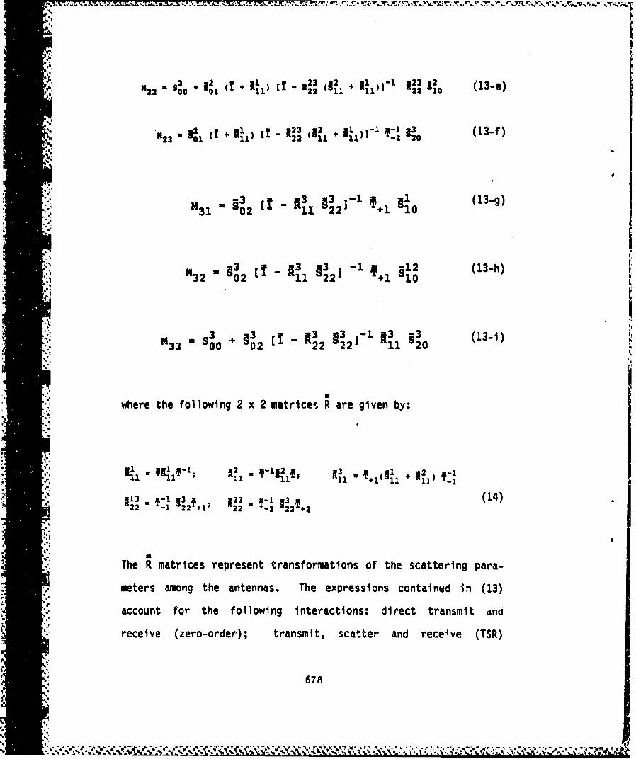
143_S *, T + 111) it - a (1 123 2 0 (13-e)
(.m.))•'. .,. l, (T + el,, (I _ 123 ,(.•j + 111))-l T:I glo (13-f)tA
,,2mm (1 A.1 -• 3 - 11 (13-f)
31 02 11 22 +1. 10
§I. u 2 - 13 1 2-12 (13-h)-- 'b32 02 11 2 2 ,a +1 10
-3 13 13 3
L33 * 0 0 ~ 02 22 2Li1 20 (31
where the following 2 x 2 matrices are given by:
22rx -12-, 2 2 2+me ter -- mn te a. -Th" e "
1-• " z . • [ s 23 .. •-l s3 • hJ4)A"
accun iiori th folwnmnercin:drcttasi n
'Ira iireceie R aties -represen transfomit, oso h scatter ad rcive pSre-
. 6,.m
)i i)• meters among the antennas. The expressions contained in (13)m
}|m .!•'•account for the following interactions: direct transmit Gnd
(i i•receive (zero-order); transmit, scatter and receive (TSR)
-': NA, Al 'A '.: A mA IN AmA . ..,4 A .

(first-order); and higher order scattering among the three
antennas. In obtaining (13) expressions fora'. b1, ; 2, ;2, and
V a , i3 are found which can be used in (2) for explicitly repre-
I senting the corresponding and H fields.
I 5. Transmit-Scatter-Receive Interaction: The Radar Problem
For simulating the radar problem, let antenna 1 transmit,
antenna 3 be passively scattering radiation, and antenna 2 be
operating in the receiving mode. Fur'ther, let antennas 1 and 2
have identical characteristics (as defined under (3) and (4))
denoted by
If mutual scattering between antennas 1 and 2 is assummed negli-S gible, then sincea 2 a3 -0, bo from (13) becomes:
=101~'- 23~ 12 g2 3 f 1 a116bo 0122 11 22 1.0 0o(6
Considering the first reflection to be dominant and subsequent
reflections to be negligible, (16) can be further reduced to:
I I679

b2 f 1 u§3 f Y1 &1 (17)-1 2 22 +1. 10 0
In explicit integral form, (17) can be written as
,bamo, a2 - -I e 2. -§3 (1•__•1~~~0 (R0r'L •O '•,E)i M'~EeL'"ld•, di
receiving rigtht to left spectraI transmitting left to*IB.. characteristics propagation dyadic Greens characteriStics right
Function propagation
and is a reduced reflection integral. If multiple reflections
are considered significant, (18) can be used as a first
2approximation to bo, and using an appropriate iterative technique
2b may be evaluated in principle if (16) is convergent. For this0i
a ,latter class of problems it may be possible to evaluate the full"unreduced" form for b2 (a -a a 0) as written in (13-d).
The reduced reflection integral (18) mathematically-. describes a TSR interaction which is the radar problem. To make
* .. A
apparent the similarity of (18) with the transmission integral
(reference 1) let
.11
I10 (r11,K) = 22 (K,L).10(L) eii1 dL (19)
680
4`Xii1ll l .

Then (18) becomes:
b 2 a -.' 2 dR (20)0b (1•1 , 2 ) - Io '. o ,
which is indeed a transmission integral. The transmit antenna
has a spectral radiation pattern i-o(r 1 ,K) which differs from
that defined under (3) only by the r 1 dependence. The scattering-'3
dyadic S represents any scattering target and the scattered
field can be considered to have originated from an antenna. As a
result, near-field antenna measurement techniques are applicable
(reference 2). Denote the coupling-product by
R RiD(K'r1 ) - 10 1 (K).1 1 0 (j 1 ,K) (21)
Oeconvolution of (21) allows O(K,rl) to be expressed as:
1*100
Since for planar near-field antenna measurment techniques bo2
represents sampled data in the transverse R2 plane, D(K,rl) can
681
p
V ¶~ *~%* ~*.%~ -*~ .v:*.~*.,.(~;%. ~

be empirically determined, and I1 o(K,rl) can be computed and
receive probe corrected via (21). A far-electric field can then
be calculated and an RCS evaluated although it will generally be
transmit probe dependent. If a plane-wave is incident upon the
target then Iij(K,rl) will not be transmit probe dependent, and
the far-electric field can be calculated and an RCS determined.
However, even ca I o(Kor) is transmit probe dependent a second
deconvolution can be performed upon (19) and S22 (K,L) evaluated.
=(Ki) is the most essential parameter in the PWSM formulation
of the RCS problem since it describes the scattering properties
of the target.
Oefining
io (K,L) = 9 2 2 (KE) 1 I10(L) (23)
as a scattering product, a second deconvolution can be written as
Q(K,L) = 1 f I~o(K,rl) e-i 1l dR (24)4w
An explicit set of equations, assuming TM(x) and TE(y)polarization, can be written as:
Q L Ii0x(L) S 2(x,K;x,L) + ISoy(L 2(x ;yL)
(25)
-KL LlOOIAJJ S22'yK~xL) I10 y(L) S22 (yK;y,L)
682
%z

n3If the transmitter is rotated and (20) through (25) resolve4, S22N3can be determined. Once known, S;22 can be used in the reflection
integral (18) allowing b2 to be calculated for any incident0field, and an RCS can be determined in the near- or far-field.
6. Discussion
The TSR interaction is compactly expressed in the reduced-
reflection integral (18). This integral describes a transmitted
radiation pattern which is propagated to a target and scattered.
Emerging from this interaction is another, re-transmitted
4, radiation pattern. This target radiation pattern is determined
by evaluating and summing the scatterIng-product (23) for all
incident directions. The target radiation pattern is then
propagated to and received by a probe antenna which also has a
particular pattern (or angular spectrum). The first deconvolu-
tion (22) allows the coupling-product (21) to be evaluated, which
in turn enables the transmit-target pattern to be determined and
receive probe corrected. A second deconvolution (24) allows the
scattering-product to be evaluated which in turn enables the
dyadic scattering tensor element to be determined and transmit
probe corrected..4 ~3 -The scattering tensor element S22 (m,K;n,L) is a quantity
which enforces the electromagnetic boundary conditions to be
satisfied for any of the incident field directions E and polari-
zations n. This enforcement of the boundary conditions is
dependent upon the target geometry and electromagnetic
683
#j4

constitutive parameters a, a and e. As such, the dyadic scat-
earing tensor element is a significant quantity for the radar
problem since it inherently contains the target geometry and
electromagnetic constitutive parameters. Since the scattering
tensor is independent of transmit and receive probes it can .be
used as a classification parameter for various targets and may
also be used for calculating a measured RCS using any set of
probes, in the near- or far-field.
A final note to be mentioned is that if the first decon-
volution required an N x N array of data, then the second decon-
volution would require an (N x N)2 array for determining S3v 22
(m,K;n,L). Efficient data acquisition and processing schemes are
needed to minimize computation memory and time requirements.
7. Conclusion
A three-antenna PWSM formulation has been presented and a
solution formally obtained. The radar problem or TSR interaction
is a special case of the three-antenna problem. A transmission
integral was obtained (20) which is similar to the one obtained
in reference 1. This substantiates using near-field antenna
measurement techniques for measuring the near-scattered field of
a target. The scattered field transmission pattern can be deter-
mined and probe corrected as in the near-field antenna measure-
ments. A near- or far-field electric field and corresponding RCS
can then be calculated. This RCS will in general be probe-
dependent. However, applying the second deconvolution (24)
684

allows the scattering-product to be evaluated and the target
scattering parameters determined and transmit probe corrected.
Using an arbitrary incident field, a near- or far-field electric
field and the corresponding RCS can be calculated.
*' Future efforts Include the following topics:
1. Analytically calculating the dyadic scattering tensor.4
elements from known scattered field solutions.
2. Performing a similar three-antenna analysis with one of
the antennas located in a plane mutually orthogonal to
the other two.
3. Determining how to simulate a "near-field" plane-wave
and thus avoid a full second deconvolutlon.
4. Fully utilizing a given near-field measurement data-
set, including simulating with software other incident
field directions.S.
Acknowledgements
Supported Under Contract F08635-83-C-0286
References
1. Newell, A. C. and Crawford, M. L.. (1974) Planar Near-Field
Measurements on High Performance Array Antennas,
NBSIR 74-380, National Bureau of Standards.
685
NN .

2. Kerns, 0. M. (1981) Plane-Wave ScatterinQ-Matrix Theory of
Antennas and Antenna-Antenna Interactions, Monograph
No. 162, National Bureau of Standards.
3. Joy, E. B. and Paris, 0. T. (1972) Spatial sampling qnd
filtering in near-field measurements, in IEEE Trans.
Antenna Propae., Vol. AP-20, pp. 253-261.
.68
li,!
im e 'U
*il '.
ani .
= a
a U
-i i -.
a:aY.LUm l *- - - -_.

MISSION
.9Of
RoeArDeeomntCne
RADCptan an exeuteAxeaatch devtopentte~
an.9etdaqu'to ~qam n4poto
ComnCnkt,,muiain adIttiec
k) The axaRoj echAira Deeompmtence CenterRACopmanicatind ecommandu 4and onto, devetopen~,.mandagementd tzcqwm6aton pue4o4am6 g. 4tppo'i.tt 0Cenommn, Con tettien domn~atac~ottcto and InatetL*.gen
91 ~~60Zpp' .6tat .6ciLn a/,e6, etecomagtnetia, panvdd t
ptommugaton6, adetemrnand an maontai, bitity
-: and eompai bittibz y
xýt