operator's manual - sears parts directoperator's manual z4218/968999281 z4219/968999511...
TRANSCRIPT

Operator's manualZ4218/968999281
Z4219/968999511
Z4824/968999512
Z5426/968999508Please read the operator's manual carefully and make sure
you understand the instructions before using the machine.English
OPERATOR'S MANUAL
RIDER
Z SERIES
Contents
Contents ................................................................... 1Introduction ............................................................. 3
Congratulations .................................................... 3General ................................................................ 3Driving and Transport on Public Roads ............... 3Towing ................................................................. 3Operating ............................................................. 3Good Service ....................................................... 4Manufacturing Number ........................................ 4
Symbols and Decals ............................................... 5Safety Instructions .................................................. 7
General Use ......................................................... 7Personal Safety Equipment ................................. 9Driving on Slopes ................................................. 9Children .............................................................. 10Utility Box ........................................................... 10Maintenance ...................................................... 11Transport ............................................................ 13Customer responsibilities ................................... 14
Controls ................................................................. 16Control Locations ............................................... 161. Motion Control Levers .................................... 172. Seat adjustment knobs .................................. 183. Fuses ............................................................. 184. By pass linkages ............................................ 195. Refueling ........................................................ 206. Blade switch ................................................... 207. Ignition Switch ................................................ 218. Choke Control ................................................ 219. Throttle Control .............................................. 2110. Hour Meter ................................................... 2211. Parking Brake .............................................. 2212. Cutting height pedal ..................................... 23Accessories ........................................................ 23
Operation ............................................................... 24Training .............................................................. 24Before Starting ................................................... 25Starting the Engine ............................................ 25To start an engine with a weak battery .............. 28Running .............................................................. 29Operating on hills ............................................... 30Mowing Tips ....................................................... 31Stopping the Engine ........................................... 32
Moving by Hand ..................................................... 33Maintenance ......................................................... 34
Maintenance Schedule ...................................... 34Battery ............................................................... 36Ignition System .................................................. 37Checking the Safety System ............................. 38Checking the Engine's Cooling Air Intake ......... 39Checking and Adjusting the Throttle Cable ....... 39Replacing the Air Filter ...................................... 40Replacing the Fuel Filter ................................... 41Checking Tire Pressures ................................... 41Checking the Parking Brake .............................. 41Checking the V-belts ......................................... 42Deck belt ........................................................... 42EZT belt ............................................................. 44Checking the Blades ......................................... 45Adjusting the Mower Deck ................................ 46Cleaning and Washing ...................................... 50Caster Wheels ................................................... 50Hardware ........................................................... 50
Lubrication ............................................................ 51Lubrication Schedule ......................................... 51General ............................................................. 51Lubricating the Cables ...................................... 52Lubricating in Accordance with the LubricationSchedule ........................................................... 52
Trouble Shooting Guide ...................................... 56Storage .................................................................. 59
Winter Storage .................................................. 59Service .............................................................. 59
Wiring diagram ..................................................... 60Technical Data ...................................................... 61
Accessories ....................................................... 65Torque Specifications ........................................ 65
Conformity Certificates ........................................ 66USA requirements ............................................. 66
Service Journal .................................................... 67Delivery Service ................................................ 67After the First 5-8 Hours .................................... 6825-Hour Service ................................................ 6950-Hour Service ................................................ 70100-Hour Service .............................................. 71300-Hour Service .............................................. 72At Least Once Each Year .................................. 73
English-1
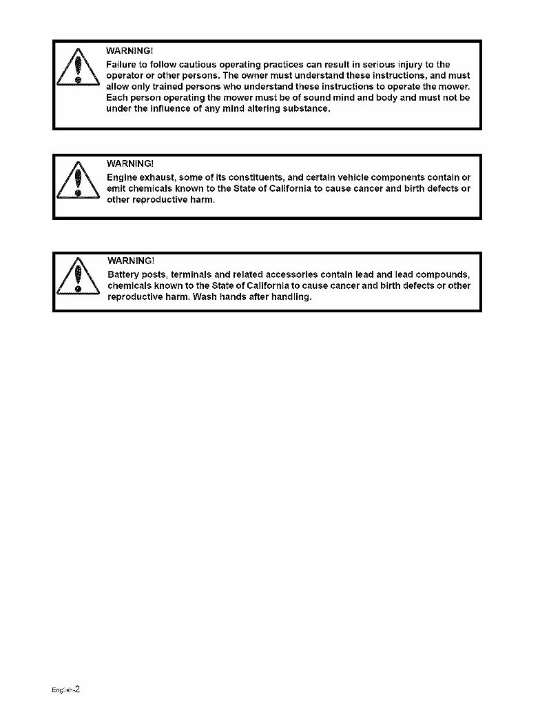
WARNING!
Failure to follow cautious operating practices can result in serious injury to theoperator or other persons. The owner must understand these instructions, and mustallow only trained persons who understand these instructions to operate the mower.Each person operating the mower must be of sound mind and body and must not beunder the influence of any mind altering substance.
WARNING!
Engine exhaust, some of its constituents, and certain vehicle components contain oremit chemicals known to the State of California to cause cancer and birth defects orother reproductive harm.
WARNING!
Battery posts, terminals and related accessories contain lead and lead compounds,chemicals known to the State of California to cause cancer and birth defects or otherreproductive harm. Wash hands after handling.
English-2
INTRODUCTION
Introduction
Congratulations
Thank you for purchasing a Husqvarna ride-on mower. This machine is built for the greatest efficiency andrapid mowing primarily of large areas. Controls in one place and a hydrostatic transmission regulated bysteering controls also contribute to the machine's performance.
This manual is a valuable document. Following the instructions (use, service, maintenance, etc.) by all whooperate this machine can considerably increase the lifespan of your machine and even increase its resalevalue. It is also very important to follow the instructions for the safety of you and others.
If you sell your machine, be sure to give the operator's manual to the new owner.
The final chapter of this operator's manual comprises a Service Journal. Ensure that service and repairwork is documented. A well kept service journal reduces service costs for the season-based maintenanceand affects the machine's resale value. Take the operator's manual along when the machine is left to theworkshop for service.
General
In this operator's manual, left and right, backward and forward are used in relation to the machine's normaldriving direction.
Continuous dedication to improve our products require that specifications and design are subject to changewithout notice.
Driving and Transport on Public Roads
Check applicable road traffic regulations before transporting on public roads. If the machine is transported,you must always use approved fastening equipment and ensure that the machine is well anchored. DONOT operate this machine on public roadways.
Towing
Do not tow this machine, it may cause damage to the drive system.
Do not tow any trailers, etc with this mower. They may jackknife or overturn causing damage to the mowerand possibly serious injury to the operator.
Operating
This machine is constructed only for mowing grass on lawns and other free and even ground withoutobstacles such as stones, tree stubs, etc. The machine can also be used for other tasks when equippedwith special accessories provided by the manufacturer, for which the operating instructions are provided inconjunction with delivery. All other types of use are incorrect. The manufacturer's directions concerningoperation, maintenance, and repairs must be carefully followed.
Lawnmowers and all power equipment, can be potentially dangerous if used improperly. Safety requiresgood judgement, careful use in accordance with these instructions and common sense.
The machine must only be operated, maintained, and repaired by persons that are familiar with themachine's special characteristics and who are well versed in the safety instructions. Use only approvedrepair parts to maintain this machine.
Accident prevention regulations, other general safety regulations, occupational safety rules, and trafficregulations must be followed without fail.
Unauthorized modifications to the design of the machine may absolve the manufacturer from liability forany resulting personal injury or property damage.
English-3
INTRODUCTION
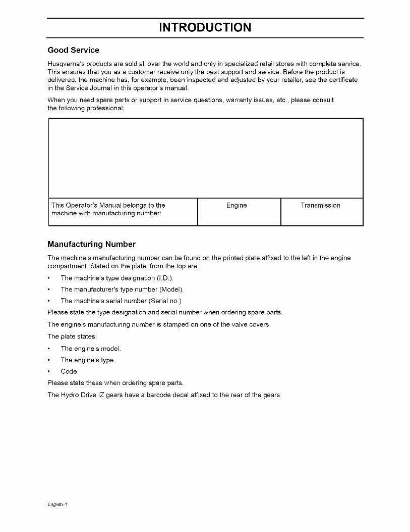
Good Service
Husqvarna's products are sold all over the world and only in specialized retail stores with complete service.This ensures that you as a customer receive only the best support and service. Before the product isdelivered, the machine has, for example, been inspected and adjusted by your retailer, see the certificatein the Service Journal in this operator's manual.
When you need spare parts or support in service questions, warranty issues, etc., please consultthe following professional:
This Operator's Manual belongs to themachine with manufacturing number:
Engine Transmission
Manufacturing Number
The machine's manufacturing number can be found on the printed plate affixed to the left in the enginecompartment. Stated on the plate, from the top are:
• The machine's type designation (I.D.).
• The manufacturer's type number (Model).
• The machine's serial number (Serial no.)
Please state the type designation and serial number when ordering spare parts.
The engine's manufacturing number is stamped on one of the valve covers.
The plate states:
• The engine's model.
• The engine's type.
• Code
Please state these when ordering spare parts.
The Hydro Drive IZ gears have a barcode decal affixed to the rear of the gears.
English-4
SYMBOLS AND DECALS
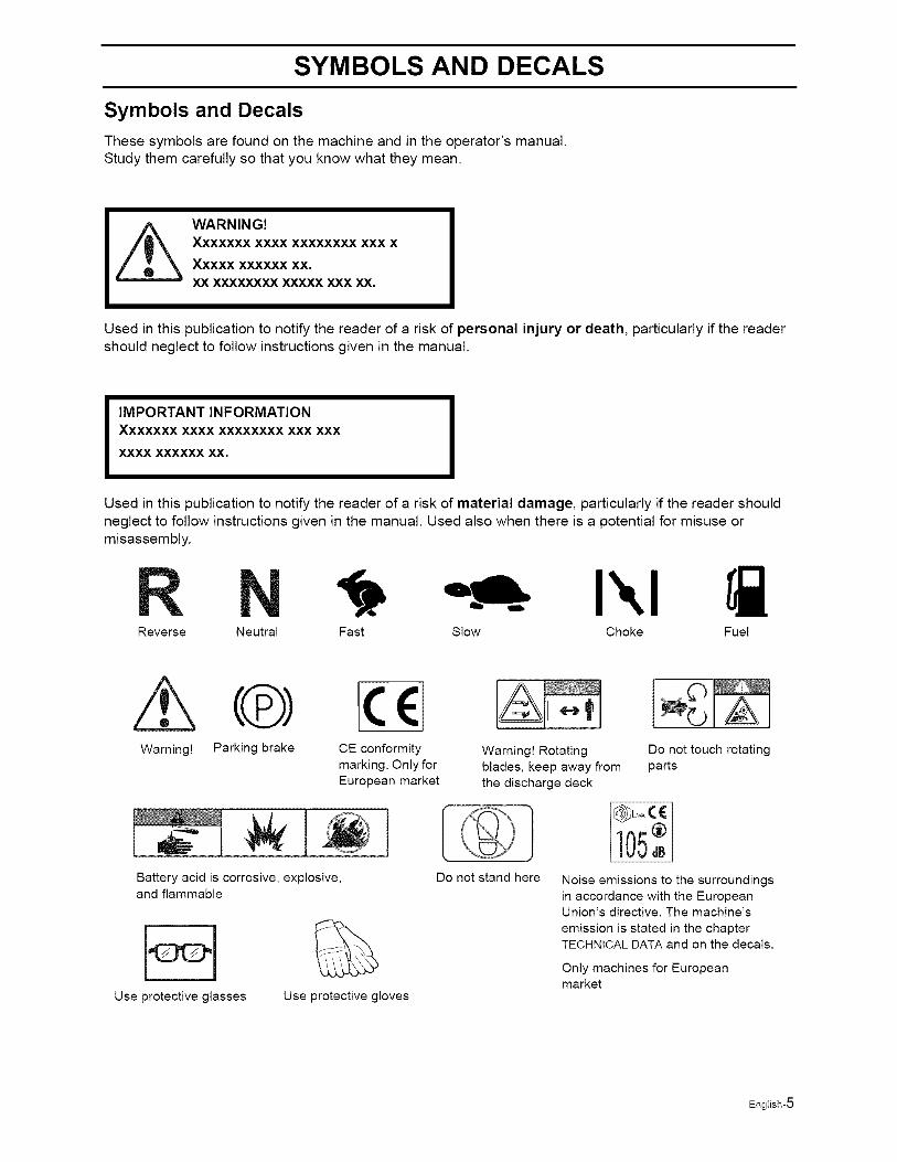
Symbols and Decals
These symbols are found on the machine and in the operator's manual.Study them carefully so that you know what they mean.
WARNING!Xxxxxxx XXXX XXXXXXXX XXX X
Xxxxx XXXXXX XX.
XX XXXXXXXX XXXXX XXX XX,
Used in this publication to notify the reader of a risk of personal injury or death, particularly if the readershould neglect to follow instructions given in the manual.
IMPORTANT INFORMATIONXxxxxxx XXXX XXXXXXXX XXX XXX
XXXX XXXXXX XX.
Used in this publication to notify the reader of a risk of material damage, particularly if the reader shouldneglect to follow instructions given in the manual. Used also when there is a potential for misuse ormisassembly.
Reverse Neutral Fast Slow Choke Fuel
Warning! Parking brake CE conformity
marking. Only for
European market
Battery acid is corrosive, explosive,and flammable
Use protective glasses
%Use protective gloves
Warning! Rotating Do not touch rotating
blades, keep away from parts
the discharge deck
Do not stand here Noise emissions to the surroundings
in accordance with the EuropeanUnion's directive. The machine's
emission is stated in the chapterTECHNICAL DATA and on the decals.
Only machines for Europeanmarket
English-5

SYMBOLS AND DECALS
Read
OperatorsManual
A
A i
Shut off engine
& remove keybefore
performing anymaintenance or
repair work.
A
Whole
body
exposureto thrown
objects.
A
Keep a safe Use ondistance from slopes nothe machine, greater
than 10°.
A
No
passengers
Severing
of fingers& toes.
Do not openor remove
safetyshields while
engine is
running.
Careful Careful goingbacking up, forward,watch for watch for
other people, other people.
DANGER
Moving sharp bladesunder cover
English-6
SAFETY INSTRUCTIONS
Safety Instructions
These instructions are for your safety. Read them carefully.
Z_ ARNING!This symbol means that important safety instructions need to be emphasized. Itconcerns your safety.
IMPORTANT: THIS CUTTING MACHINE IS CAPABLE OF AMPUTATING HANDS AND FEET ANDTHROWING OBJECTS. FAILURE TO OBSERVE THE FOLLOWING SAFETY INSTRUCTIONS COULDRESULT IN SERIOUS INJURY OR DEATH.
General Operation
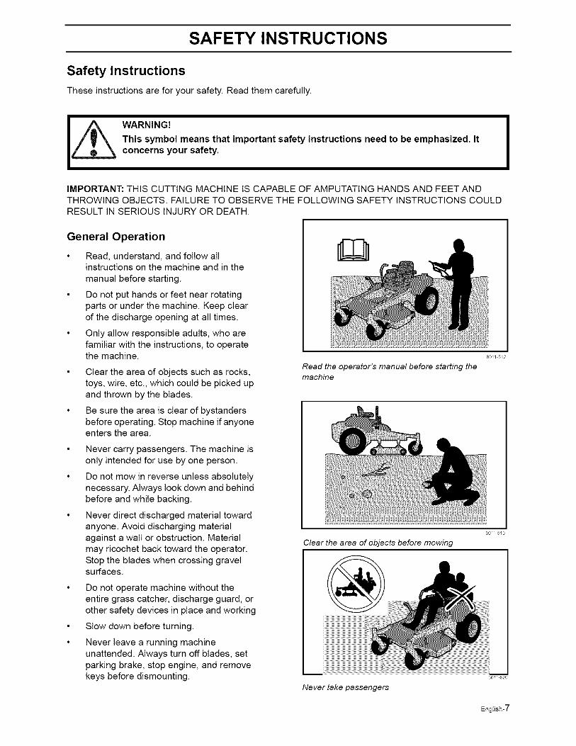
Read, understand, and follow allinstructions on the machine and in themanual before starting.
Do not put hands or feet near rotatingparts or under the machine. Keep clearof the discharge opening at all times.
Only allow responsible adults, who arefamiliar with the instructions, to operatethe machine.
Clear the area of objects such as rocks,toys, wire, etc., which could be picked upand thrown by the blades.
Be sure the area is clear of bystandersbefore operating. Stop machine if anyoneenters the area.
Never carry passengers. The machine isonly intended for use by one person.
Do not mow in reverse unless absolutelynecessary. Always look down and behindbefore and while backing.
Never direct discharged material towardanyone. Avoid discharging materialagainst a wall or obstruction. Materialmay ricochet back toward the operator.Stop the blades when crossing gravelsurfaces.
Do not operate machine without theentire grass catcher, discharge guard, orother safety devices in place and working
Slow down before turning.
Never leave a running machineunattended. Always turn off blades, setparking brake, stop engine, and removekeys before dismounting.
Read the operator's manual before starting themachine
80/I 512
80// 513
Clear the area of objects before mowing
Never take passengers
English-7

SAFETY INSTRUCTIONS
Disengage blades when not mowing.Shut off engine and wait for all parts tocome to a complete stop before cleaningthe machine, removing the grasscatcher, or unclogging the dischargeguard.
Operate machine only in daylight or goodartificial light.
Do not operate the machine while underthe influence of alcohol or drugs.
Watch for traffic when operating near orcrossing roadways.
Use extra care when loading orunloading the machine into a trailer ortruck.
• Always wear eye protection whenoperating machine.
• Data indicates that operators, age 60years and above, are involved in a largepercentage of riding mower-relatedinjuries. These operators shouldevaluate their ability to operate the ridingmower safely enough to protectthemselves and others from seriousinjury.
• Follow the manufacturer'srecommendation for wheel weights orcounterweights.
• Never allow children or other persons nottrained in the use of the machine to useor service it. Local laws may regulate theage of the user. Anyone who operatesthis machine should first read andunderstand this Operator's Manual.
• Keep machine free of grass, leaves orother debris build-up which can touch hotexhaust / engine parts and burn. Do notallow the mower deck to plow leaves orother debris which can cause build-up tooccur. Clean any oil or fuel spillagebefore operating or storing the machine.Allow machine to cool before storage.
WARNING!
Engine exhaust and certainvehicle components containor emit chemicals consideredto cause cancer, birth defects,or other reproductive systemdamage. The engine exhaustcontains carbon monoxide,which is a odorless, colorless,poisonous gas. Do not use themachine in enclosed spaces.
English-8
SAFETY INSTRUCTIONS
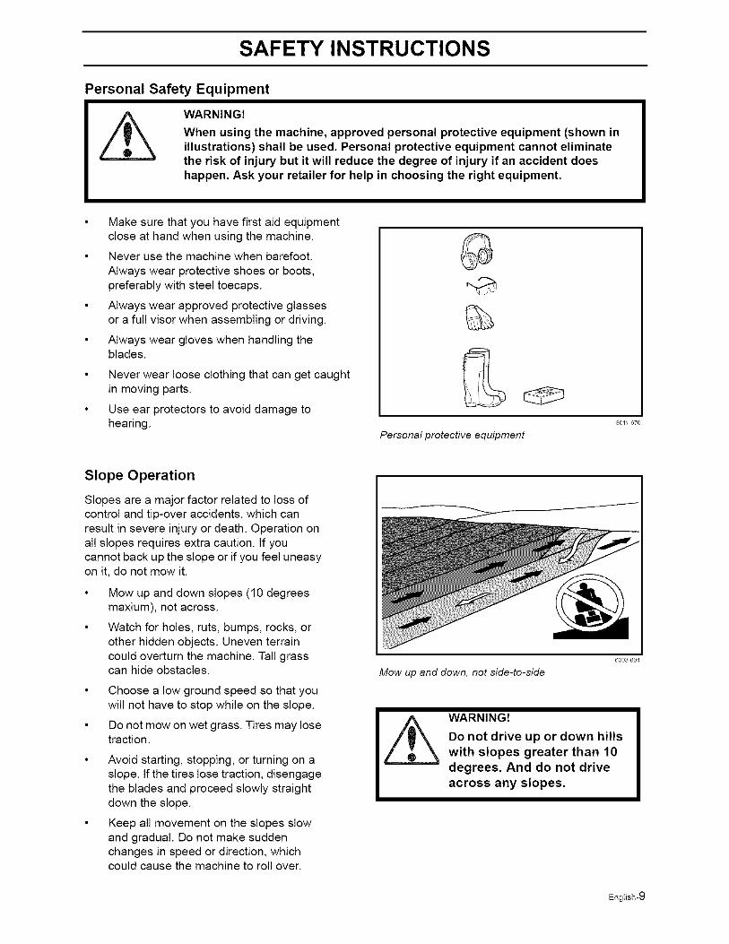
Personal Safety Equipment
WARNING!
When using the machine, approved personal protective equipment (shown inillustrations) shall be used. Personal protective equipment cannot eliminatethe risk of injury but it will reduce the degree of injury if an accident doeshappen. Ask your retailer for help in choosing the right equipment.
Make sure that you have first aid equipmentclose at hand when using the machine.
Never use the machine when barefoot.
Always wear protective shoes or boots,preferably with steel toecaps.
Always wear approved protective glassesor a full visor when assembling or driving.
Always wear gloves when handling theblades.
Never wear loose clothing that can get caughtin moving parts.
Use ear protectors to avoid damage tohearing.
Personal protective equipment
80/1 670
Slope Operation
Slopes are a major factor related to loss ofcontrol and tip-over accidents, which canresult in severe injury or death. Operation onall slopes requires extra caution. If youcannot back up the slope or if you feel uneasyon it, do not mow it.
Mow up and down slopes (10 degreesmaxium), not across.
Watch for holes, ruts, bumps, rocks, orother hidden objects. Uneven terraincould overturn the machine. Tall grasscan hide obstacles.
Choose a low ground speed so that youwill not have to stop while on the slope.
Do not mow on wet grass. Tires may losetraction.
Avoid starting, stopping, or turning on aslope. If the tires lose traction, disengagethe blades and proceed slowly straightdown the slope.
Keep all movement on the slopes slowand gradual. Do not make suddenchanges in speed or direction, whichcould cause the machine to roll over.
Mow up and down, not side-to-side
J
6003 004
English-9
SAFETY INSTRUCTIONS
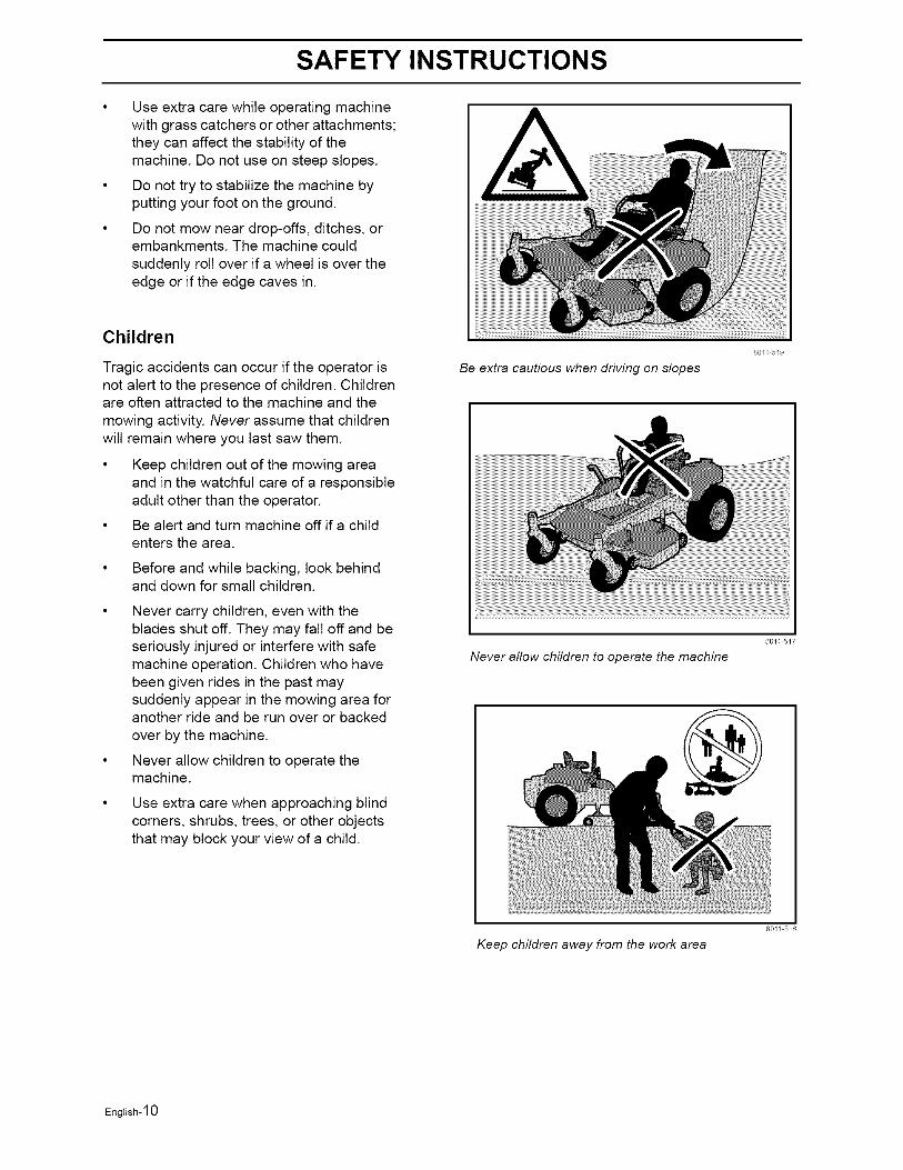
Use extra care while operating machinewith grass catchers or other attachments;they can affect the stability of themachine. Do not use on steep slopes.
Do not try to stabilize the machine byputting your foot on the ground.
Do not mow near drop-offs, ditches, orembankments. The machine couldsuddenly roll over if a wheel is over theedge or if the edge caves in.
Children
Tragic accidents can occur if the operator isnot alert to the presence of children. Childrenare often attracted to the machine and themowing activity. Never assume that childrenwill remain where you last saw them.
• Keep children out of the mowing areaand in the watchful care of a responsibleadult other than the operator.
• Be alert and turn machine off if a childenters the area.
• Before and while backing, look behindand down for small children.
• Never carry children, even with theblades shut off. They may fall off and beseriously injured or interfere with safemachine operation. Children who havebeen given rides in the past maysuddenly appear in the mowing area foranother ride and be run over or backedover by the machine.
• Never allow children to operate themachine.
• Use extra care when approaching blindcorners, shrubs, trees, or other objectsthat may block your view of a child.
Be extra cautious when driving on slopes
801/ 5/9
801/ 5/7
Never allow children to operate the machine
Keep children away from the work area
80// 5/8
English-10
SAFETY INSTRUCTIONS
Maintenance
/_ WARNING!The engine must not be started when the driver's floor plate or any protective platefor the mower deck's drive belt is removed.
Safe Handling of Gasoline
To avoid personal injury or property damage,use extreme care in handling gasoline.Gasoline is extremely flammable and thevapors are explosive.
Extinguish all cigarettes, cigars, pipes,and other sources of ignition.
Use only approved gasoline container.
Never remove gas cap or add fuel withthe engine running. Allow engine to coolat least two (2) minutes before refueling.
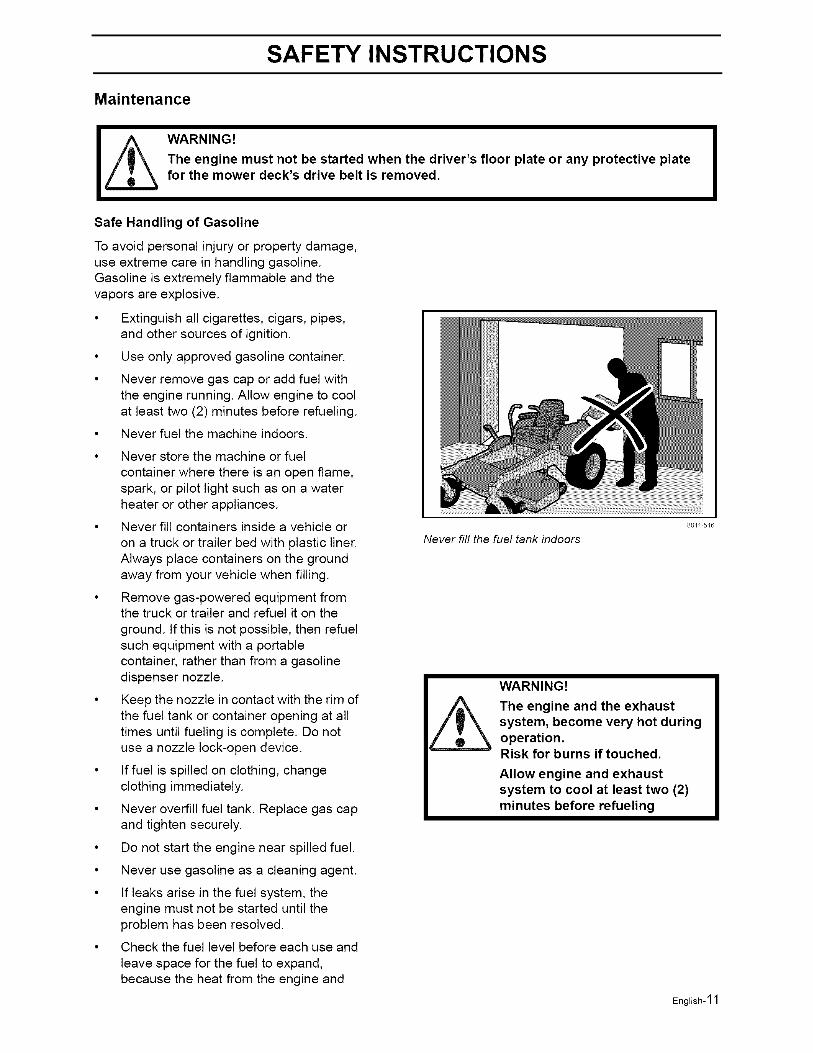
Never fuel the machine indoors.
Never store the machine or fuelcontainer where there is an open flame,spark, or pilot light such as on a waterheater or other appliances.
Never fill containers inside a vehicle oron a truck or trailer bed with plastic liner.Always place containers on the groundaway from your vehicle when filling.
Remove gas-powered equipment fromthe truck or trailer and refuel it on the
ground. If this is not possible, then refuelsuch equipment with a portablecontainer, rather than from a gasolinedispenser nozzle.
Keep the nozzle in contact with the rim ofthe fuel tank or container opening at alltimes until fueling is complete. Do notuse a nozzle lock-open device.
If fuel is spilled on clothing, changeclothing immediately.
Never overfill fuel tank. Replace gas capand tighten securely.
Do not start the engine near spilled fuel.
Never use gasoline as a cleaning agent.
If leaks arise in the fuel system, theengine must not be started until theproblem has been resolved.
Check the fuel level before each use and
leave space for the fuel to expand,because the heat from the engine and
Never fill the fuel tank indoors
80/I 516
English-11
SAFETY INSTRUCTIONS
the sun may otherwise cause the fuel toexpand and overflow.
General Maintenance
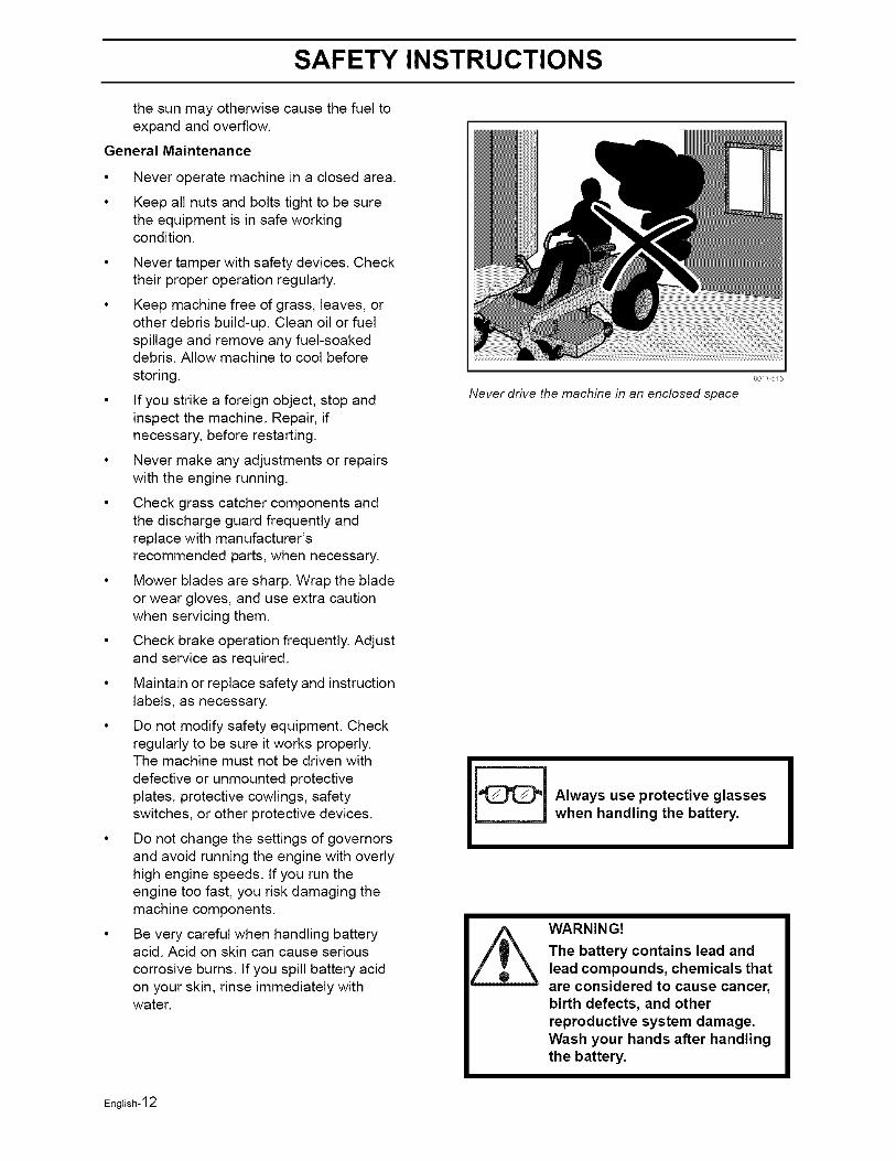
Never operate machine in a closed area.
Keep all nuts and bolts tight to be surethe equipment is in safe workingcondition.
Never tamper with safety devices. Checktheir proper operation regularly.
Keep machine free of grass, leaves, orother debris build-up. Clean oil or fuelspillage and remove any fuel-soakeddebris. Allow machine to cool before
storing.
If you strike a foreign object, stop andinspect the machine. Repair, ifnecessary, before restarting.
Never make any adjustments or repairswith the engine running.
Check grass catcher components andthe discharge guard frequently andreplace with manufacturer'srecommended parts, when necessary.
Mower blades are sharp. Wrap the bladeor wear gloves, and use extra cautionwhen servicing them.
Check brake operation frequently. Adjustand service as required.
Maintain or replace safety and instructionlabels, as necessary.
Do not modify safety equipment. Checkregularly to be sure it works properly.The machine must not be driven with
defective or unmounted protectiveplates, protective cowlings, safetyswitches, or other protective devices.
Do not change the settings of governorsand avoid running the engine with overlyhigh engine speeds. If you run theengine too fast, you risk damaging themachine components.
Be very careful when handling batteryacid. Acid on skin can cause serious
corrosive burns. If you spill battery acidon your skin, rinse immediately withwater.
Never drive the machine in an enclosed space
80/1 5E5
Always use protective glasseswhen handling the battery.
_ ARNING!The battery contains lead andlead compounds, chemicals thatare considered to cause cancer,birth defects, and otherreproductive system damage.Wash your hands after handlingthe battery.
English-12
SAFETY INSTRUCTIONS
Acid in the eyes can cause blindness,contact a doctor immediately.
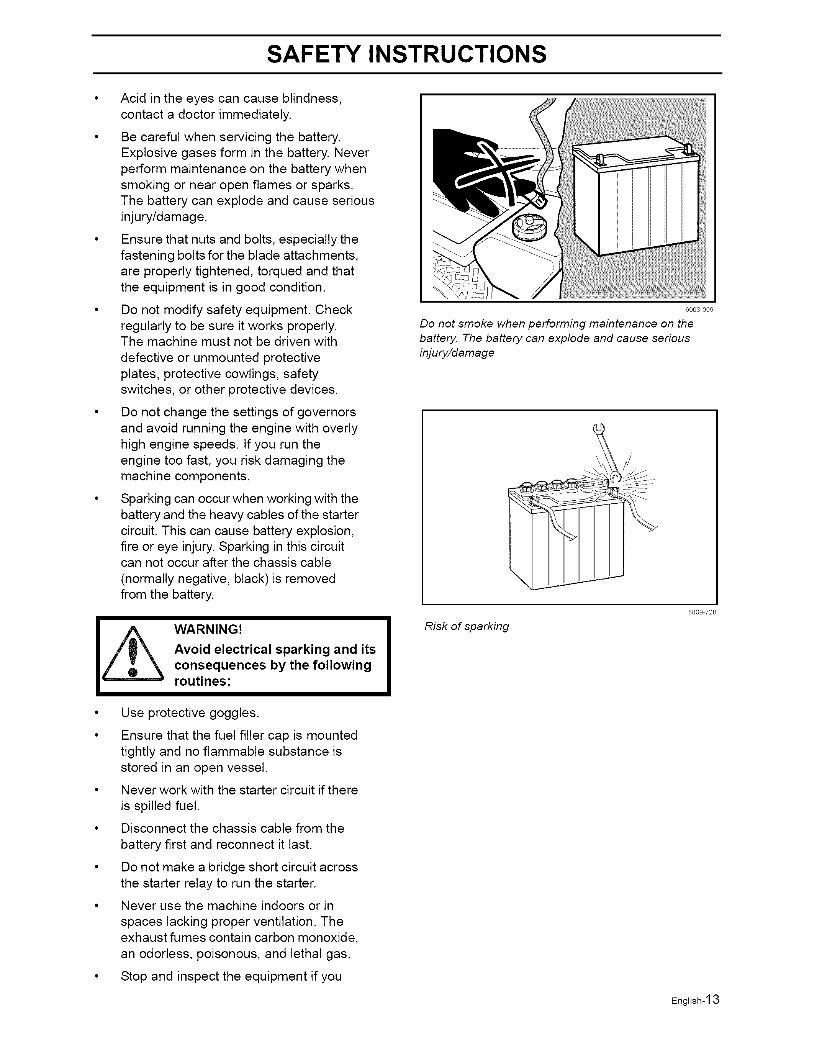
Be careful when servicing the battery.Explosive gases form in the battery. Neverperform maintenance on the battery whensmoking or near open flames or sparks.The battery can explode and cause seriousinjury/damage.
Ensure that nuts and bolts, especially thefastening bolts for the blade attachments,are properly tightened, torqued and thatthe equipment is in good condition.
Do not modify safety equipment. Checkregularly to be sure it works properly.The machine must not be driven with
defective or unmounted protectiveplates, protective cowlings, safetyswitches, or other protective devices.
Do not change the settings of governorsand avoid running the engine with overlyhigh engine speeds. If you run theengine too fast, you risk damaging themachine components.
Sparking can occur when working with thebattery and the heavy cables of the startercircuit. This can cause battery explosion,fire or eye injury. Sparking in this circuitcan not occur after the chassis cable
(normally negative, black) is removedfrom the battery.
IzL• Use protective goggles.
• Ensure that the fuel filler cap is mountedtightly and no flammable substance isstored in an open vessel.
• Never work with the starter circuit if there
is spilled fuel.
• Disconnect the chassis cable from the
battery first and reconnect it last.
• Do not make a bridge short circuit acrossthe starter relay to run the starter.
• Never use the machine indoors or in
spaces lacking proper ventilation. Theexhaust fumes contain carbon monoxide,an odorless, poisonous, and lethal gas.
• _op and inspect the equipment if you
WARNING!
Avoid electrical sparking and itsconsequences by the followingroutines:
6003 009
Do not smoke when performing maintenance on the
battery. The battery can explode and cause serious
injury/damage
Risk of sparking
8009 728
English-13
SAFETY INSTRUCTIONS
run over or into anything. If necessary,make repairs before starting.
Never make adjustments with the enginerunning.
The machine is tested and approved onlywith the equipment originally provided orrecommended by the manufacturer. Onlyuse approved repair parts for themachine.
The blades are sharp and can causecuts and gashes. Wrap the blades or useprotective gloves when handling them.
Check the parking brake's functionalityregularly. Adjust and service asnecessary.
The mulch blades should only be used infamiliar areas when higher qualitymowing is desired.
Reduce the risk of fire by removinggrass, leaves, and other debris that mayhave accumulated on the machine. Allow
the machine to cool before putting it instorage.
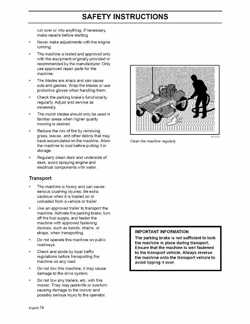
Regularly clean deck and underside ofdeck, avoid spraying engine andelectrical components with water.
Transport
The machine is heavy and can causeserious crushing injuries. Be extracautious when it is loaded on orunloaded from a vehicle or trailer.
Use an approved trailer to transport themachine. Activate the parking brake, turnoff the fuel supply, and fasten themachine with approved fasteningdevices, such as bands, chains, orstraps, when transporting.
Do not operate this machine on publicroadways.
Check and abide by local trafficregulations before transporting themachine on any road.
Do not tow this machine, it may causedamage to the drive system.
Do not tow any trailers, etc. with thismower. They may jackknife or overturncausing damage to the mower andpossibly serious injury to the operator.
80/1 644
Clean the machine regularly
IMPORTANT INFORMATION
The parking brake is not sufficient to lockthe machine in place during transport.Ensure that the machine is well fastenedto the transport vehicle. Always reversethe machine onto the transport vehicle toavoid tipping it over.
English-14

SAFETY INSTRUCTIONS
Customer responsibilities
• Read and observe the safety rules.
• Follow a regular schedule in maintaining,caring for and using your mower.
• Follow the instructions under
"Maintenance" and "Storage" sections ofthis owner's manual.
• This machine has no brain. Use yours!
WARNING!
This mower is equipped with an internal combustion engine and should not beused on or near any unimproved forest-covered, bush-covered or grass-coveredland unless the engine's exhaust system is equipped with a spark arrestermeeting applicable local or state laws (if any). If a spark arrester is used, it shouldbe maintained in effective working order by the operator.
A spark arrester for the muffler is available through your authorized Husqvarna dealer.
English-15
CONTROLS
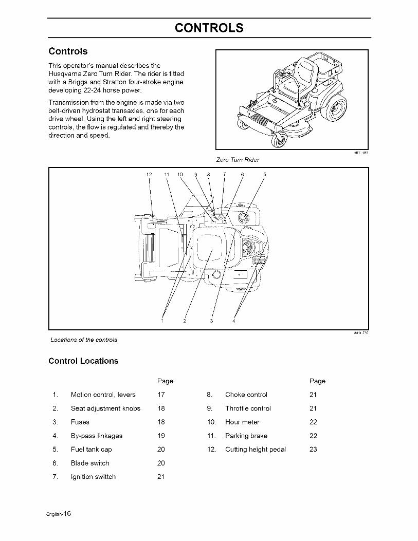
Controls
This operator's manual describes theHusqvarna Zero Turn Rider. The rider is fittedwith a Briggs and Stratton four-stroke enginedeveloping 22-24 horse power.
Transmission from the engine is made via twobelt-driven hydrostat transaxles, one for eachdrive wheel. Using the left and right steeringcontrols, the flow is regulated and thereby thedirection and speed.
Zero Turn Rider
12 11 10 9 8 7 6 5
80E/ 648
Locations of the controls
80/1 735
Control Locations
1. Motion control, levers
2. Seat adjustment knobs
3. Fuses
4. By-pass linkages
5. Fuel tank cap
6. Blade switch
7. Ignition swittch
Page
17
18
18
19
2O
2O
21
8. Choke control
9. Throttle control
10. Hour meter
11. Parking brake
12. Cutting height pedal
Page
21
21
22
22
23
English-16
CONTROLS
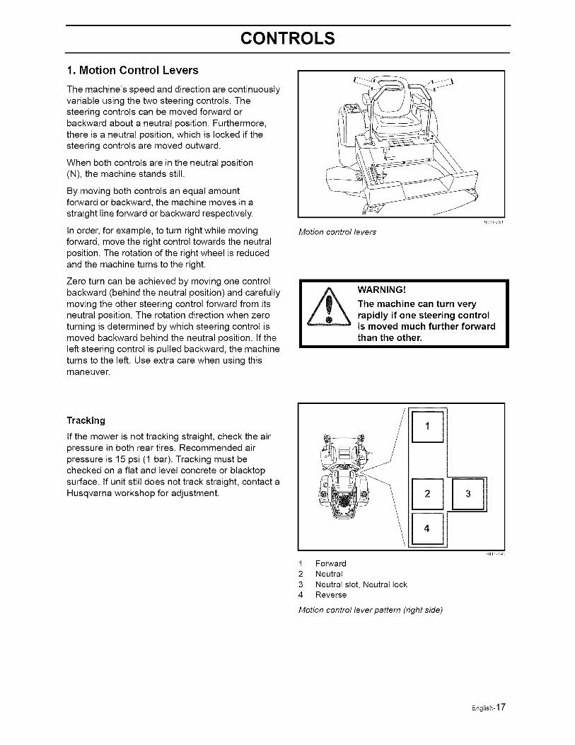
1. Motion Control Levers
The machine's speed and direction are continuouslyvariable using the two steering controls. Thesteering controls can be moved forward orbackward about a neutral position. Furthermore,there is a neutral position, which is locked if thesteering controls are moved outward.
When both controls are in the neutral position(N), the machine stands still.
By moving both controls an equal amountforward or backward, the machine moves in astraight line forward or backward respectively.
In order, for example, to turn right while movingforward, move the right control towards the neutralposition. The rotation of the right wheel is reducedand the machine turns to the right.
Zero turn can be achieved by moving one controlbackward (behind the neutral position) and carefullymoving the other steering control forward from itsneutral position. The rotation direction when zeroturning is determined by which steering control ismoved backward behind the neutral position, tf theleft steering control is pulled backward, the machineturns to the left. Use extra care when using thismaneuver.
Motion control levers
801/ 751
WARNING!
The machine can turn veryrapidly if one steering controlis moved much further forwardthan the other.
Tracking
If the mower is not tracking straight, check the airpressure in both rear tires. Recommended airpressure is 15 psi (1 bar). Tracking must bechecked on a flat and level concrete or blacktopsurface, tf unit still does not track straight, contact aHusqvarna workshop for adjustment.
4
1 Forward
2 Neutral
3 Neutral slot, Neutral lock4 Reverse
Motion control lever pattern (right side)
80E/ 791
English-17
CONTROLS
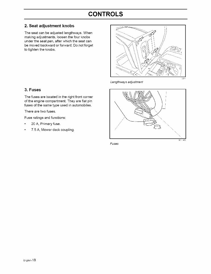
2. Seat adjustment knobs
The seat can be adjusted lengthways. Whenmaking adjustments, loosen the four knobsunder the seat pan, after which the seat canbe moved backward or forward. Do not forgetto tighten the knobs.
3. Fuses
The fuses are located in the right front cornerof the engine compartment. They are flat pinfuses of the same type used in automobiles.
There are two fuses.
Fuse ratings and functions:
• 20 A, Primary fuse.
• 7.5 A, Mower deck coupling.
cz /
Lengthways adjustment
Fuses
\\\\\\\\\\\
801/ 483
English-18
CONTROLS
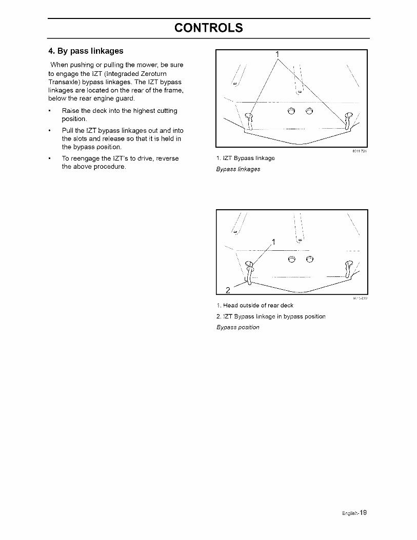
4. By pass linkages
When pushing or pulling the mower, be sureto engage the IZT (lntegraded ZeroturnTransaxle) bypass linkages. The IZT bypasslinkages are located on the rear of the frame,below the rear engine guard.
Raise the deck into the highest cuttingposition.
Pull the IZT bypass linkages out and intothe slots and release so that it is held inthe bypass position.
To reengage the lZT's to drive, reversethe above procedure.
i/ //
© ©
1. IZT Bypass linkage
Bypass linkages
'\\\
\\\
\\
8011 721
/ ' 'i iii
2
1. Head outside of rear deck
2. IZT Bypass linkage in bypass position
Bypass position
\\\
\
\\
\\
80/1 722
English-19
CONTROLS
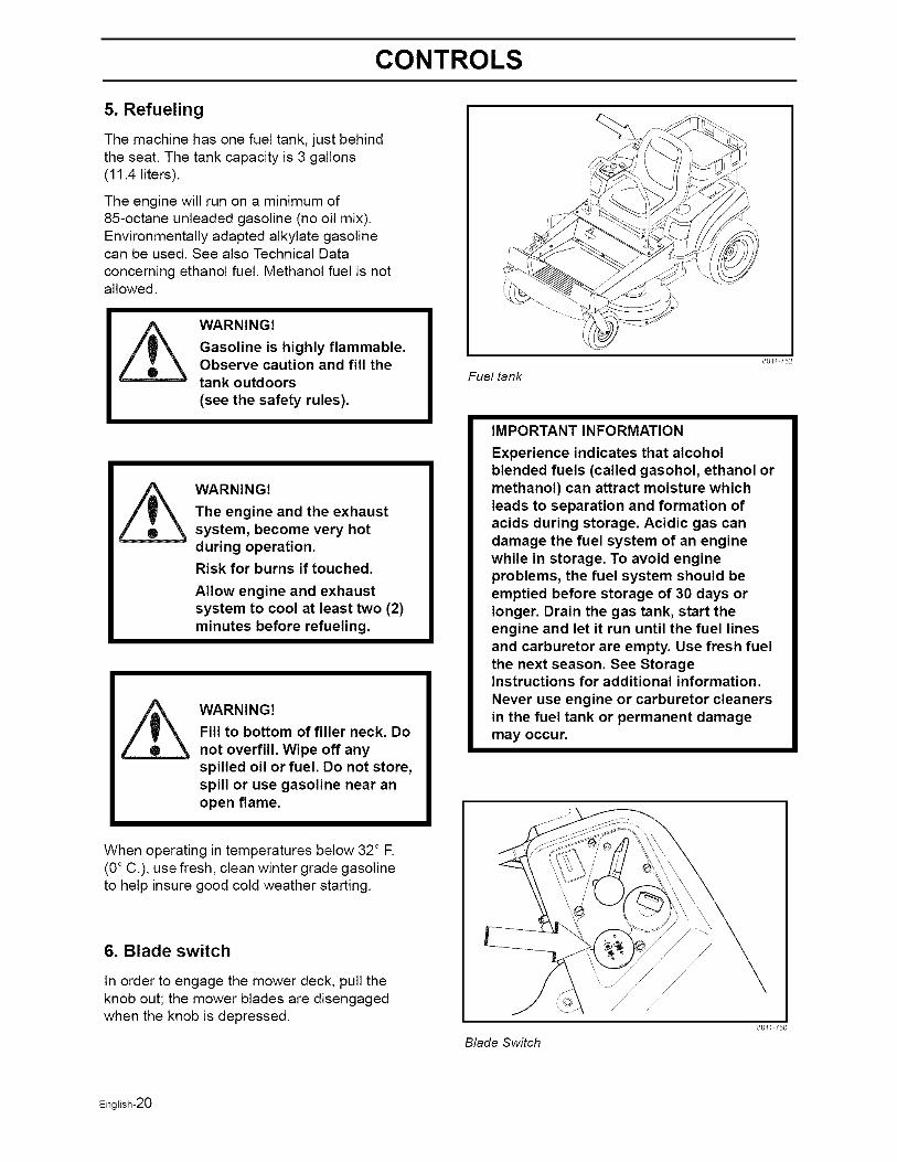
5. Refueling
The machine has one fuel tank, just behindthe seat. The tank capacity is 3 gallons(11.4 liters).
The engine will run on a minimum of85-octane unleaded gasoline (no oil mix).Environmentally adapted alkylate gasolinecan be used. See also Technical Data
concerning ethanol fuel. Methanol fuel is notallowed.
WARNING!
Gasoline is highly flammable.Observe caution and fill thetank outdoors(see the safety rules).
WARNING!
The engine and the exhaustsystem, become very hotduring operation.
Risk for burns if touched.
Allow engine and exhaustsystem to cool at least two (2)minutes before refueling.
Z_ WARNING!Fill to bottom of filler neck. Do
not overfill. Wipe off anyspilled oil or fuel. Do not store,spill or use gasoline near anopen flame.
When operating in temperatures below 32° R(0° C.), use fresh, clean winter grade gasolineto help insure good cold weather starting.
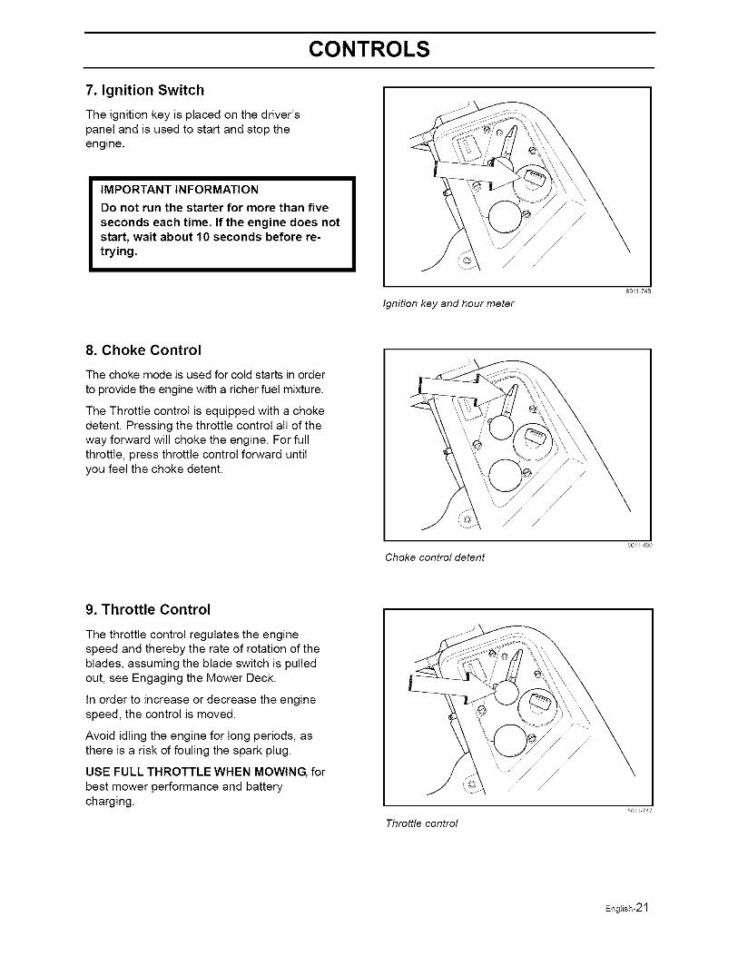
6. Blade switch
In order to engage the mower deck, pull theknob out; the mower blades are disengagedwhen the knob is depressed.
Fuel tank
IMPORTANT INFORMATION
Experience indicates that alcoholblended fuels (called gasohol, ethanol ormethanol) can attract moisture whichleads to separation and formation ofacids during storage. Acidic gas candamage the fuel system of an enginewhile in storage. To avoid engineproblems, the fuel system should beemptied before storage of 30 days orlonger. Drain the gas tank, start theengine and let it run until the fuel linesand carburetor are empty. Use fresh fuelthe next season. See StorageInstructions for additional information.Never use engine or carburetor cleanersin the fuel tank or permanent damagemay occur.
Blade Switch
80/1 752
801/ 750
English-20
CONTROLS
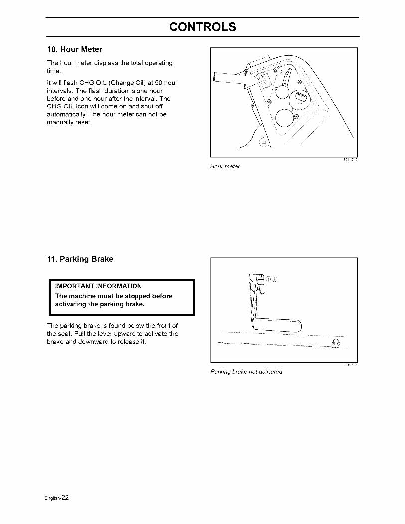
7. Ignition Switch
The ignition key is placed on the driver'spanel and is used to start and stop theengine.
IMPORTANT INFORMATION
Do not run the starter for more than five
seconds each time. If the engine does notstart, wait about 10 seconds before re-trying.
Ignition key and hour meter
80/1 748
8. Choke Control
The choke mode is used for cold starts in orderto provide the engine with a richer fuel mixture.
The Throttle control is equipped with a chokedetent. Pressing the throttle control all of theway forward will choke the engine. For fullthrottle, press throttle control forward untilyou feel the choke detent.
Choke control detent
80El 480
9. Throttle Control
The throttle control regulates the enginespeed and thereby the rate of rotation of theblades, assuming the blade switch is pulledout, see Engaging the Mower Deck.
In order to increase or decrease the enginespeed, the control is moved.
Avoid idling the engine for long periods, asthere is a risk of fouling the spark plug.
USE FULL THROTTLE WHEN MOWING, forbest mower performance and batterycharging.
Throttle control
8011 747
English-21
CONTROLS
10. Hour Meter
The hour meter displays the total operatingtime.
It will flash CHG OIL (Change Oil) at 50 hourintervals. The flash duration is one hourbefore and one hour after the interval. TheCHG OIL icon will come on and shut off
automatically. The hour meter can not bemanually reset.
Hour meter
80/1 749
11. Parking Brake
IMPORTANT INFORMATION
The machine must be stopped beforeactivating the parking brake.
The parking brake is found below the front ofthe seat. Pull the lever upward to activate thebrake and downward to release it.
801/ 481
Parking brake not activated
English-22
CONTROLS
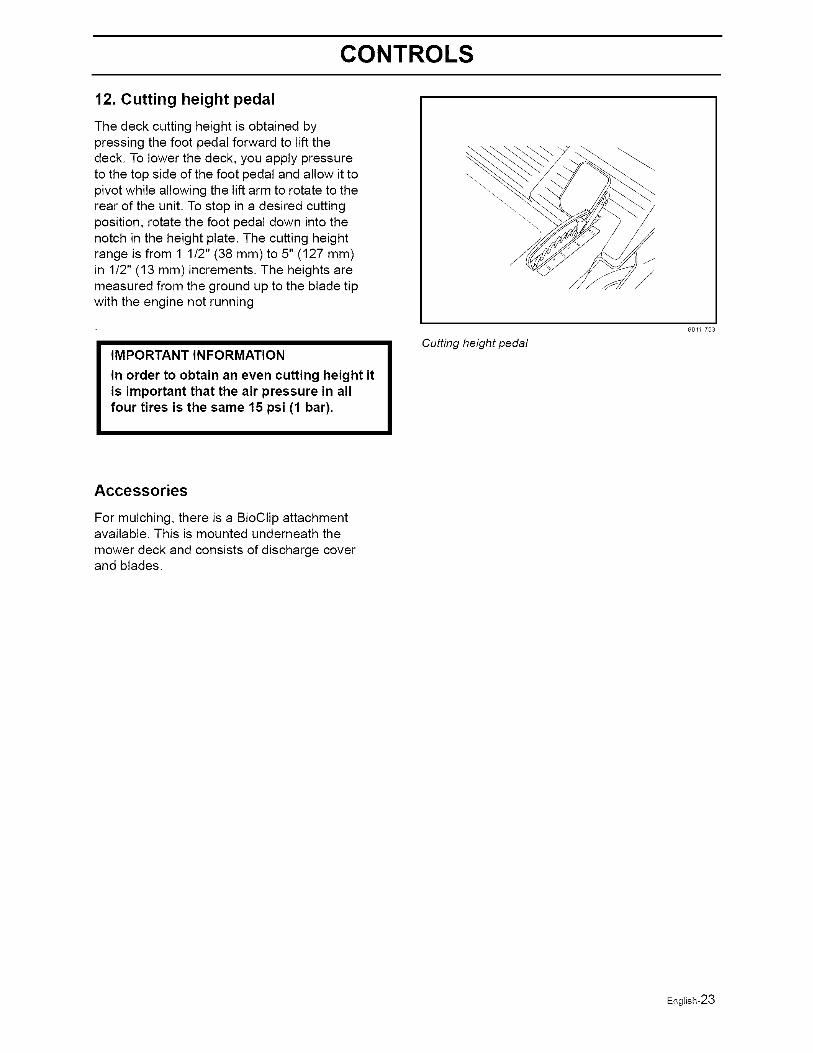
12. Cutting height pedal
The deck cutting height is obtained bypressing the foot pedal forward to lift thedeck. To lower the deck, you apply pressureto the top side of the foot pedal and allow it topivot while allowing the lift arm to rotate to therear of the unit. To stop in a desired cuttingposition, rotate the foot pedal down into thenotch in the height plate. The cutting heightrange is from 1 1/2" (38 mm) to 5" (127 mm)in 1/2" (13 mm) increments. The heights aremeasured from the ground up to the blade tipwith the engine not running
IMPORTANT INFORMATION
In order to obtain an even cutting height itis important that the air pressure in allfour tires is the same 15 psi (1 bar).
Cutting height pedal
8011 753
Accessories
For mulching, there is a BioClip attachmentavailable. This is mounted underneath themower deck and consists of discharge coverand blades.
English-23
OPERATION
Operation
Read "Safety Instructions" section and following pages, if you are unfamiliar with the machine.
Training
Zero turn mowers are far more manueverable than typical riding mowers due to their unique steeringcapabilities.
We suggest when first operating the mower, use a reduced throttle speed and reduced ground speed byNOT moving control levers to the furthest forward or reverse positions during initial operation, or untiloperator becomes comfortable with controls. We also suggest first time users, or new users to ZeroTurnmowers to become familiar with the mowers movement on a hard surface, such as concrete or blacktopPRIOR to attempting to operate on turf. Until operator becomes comfortable with mower controls and zeroturning capability, they may damage turf due to over aggressive maneuvers.
To move forward and backward
The direction and speed of the mowers movements is effected by the movement of the control lever(s) oneach side of mower. The left control lever controls the left wheel. The right control lever controls the rightwheel.
IMPORTANT INFORMATION
When control levers are in the reverseposition they return to neutral whenreleased. This may cause the mower tosuddenly stop.
First time users should push mower (see "Moving by Hand" in the "Operation" section) to an open, flat area,without other people or vehicles/obstacles near by. In order to move unit under its own power, the operatormust be in the seat, start engine (see "Before Starting" in "Operation" section), adjust engine speed to idle,disengage parking brake, do not engage blades at this time, rotate control levers inward. As long as thecontrol levers have not been moved forward or backwards, mower will not move. Slowly move both controllevers forward slightly, this will allow mower to start moving forward in a straight line. Pull back on controllevers to the neutral position and mower should stop moving. Pull back slightly on control levers, this willallow mower to start moving backwards. Push forward on control levers to the neutral position and mowershould stop moving.
To turn to the right
While moving in a forward direction, pull the right lever back towards the neutral position while maintainingthe position of the left lever, this will slow the rotation of the right wheel and cause the machine to turn inthat direction.
To turn to the left
While moving in a forward direction pull the left lever back towards the neutral position while maintainingthe position of the right lever, this will slow the rotation of the left wheel and cause the machine to turn inthat direction.
To zero turn
While moving in a forward direction, first pull both control levers back until the mower stops or slowsdramatically. Then by alternating one lever slightly to the forward position and the other in the reverseposition.
English-24
OPERATION
Before Starting
Read the sections Safety Instructionsand Controls before starting themachine.
Perform the daily maintenance beforestarting (see Maintenance Schedulein the Maintenance section).
Check that there is sufficient fuel in thefuel tank.
• Adjust the seat to the desired position.
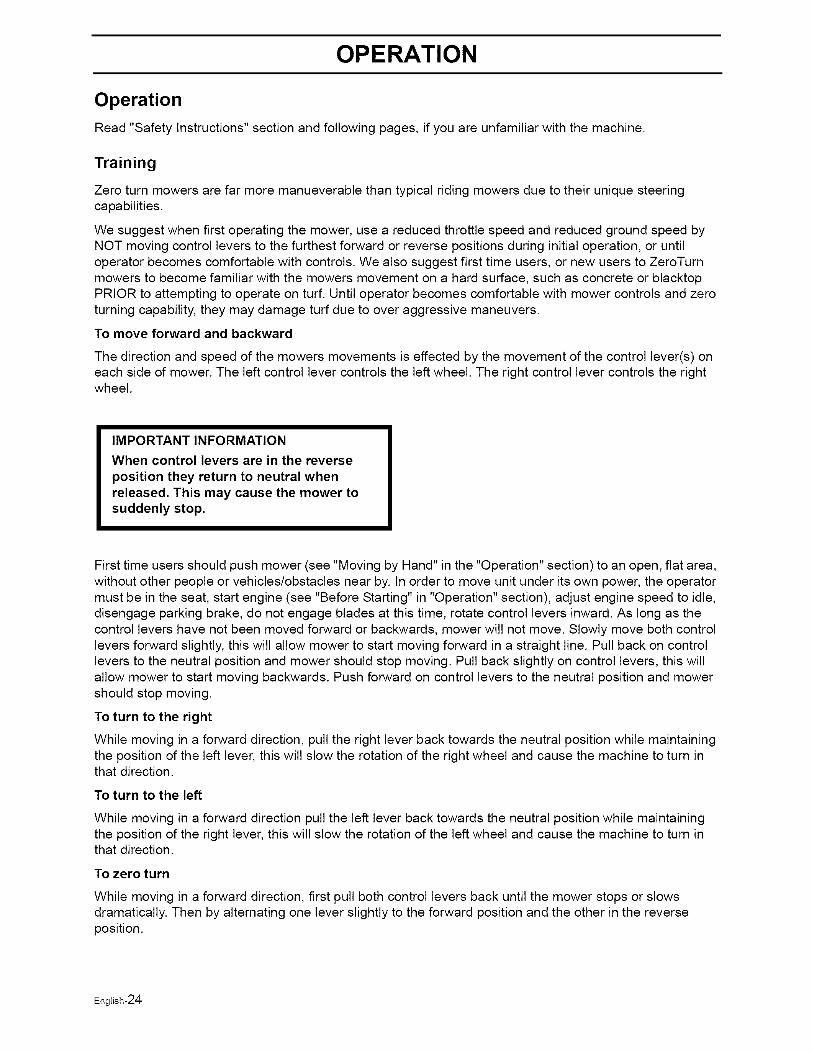
The following conditions must be fulfilledbefore the engine can be started:
• The driver must be seated on the seat.
The blade switch for engaging the mowerblades must be depressed.
The parking brake must be on.
Both steering controls must be in thelocked (outer) neutral position.
Start conditions
801/ 484
Starting the Engine
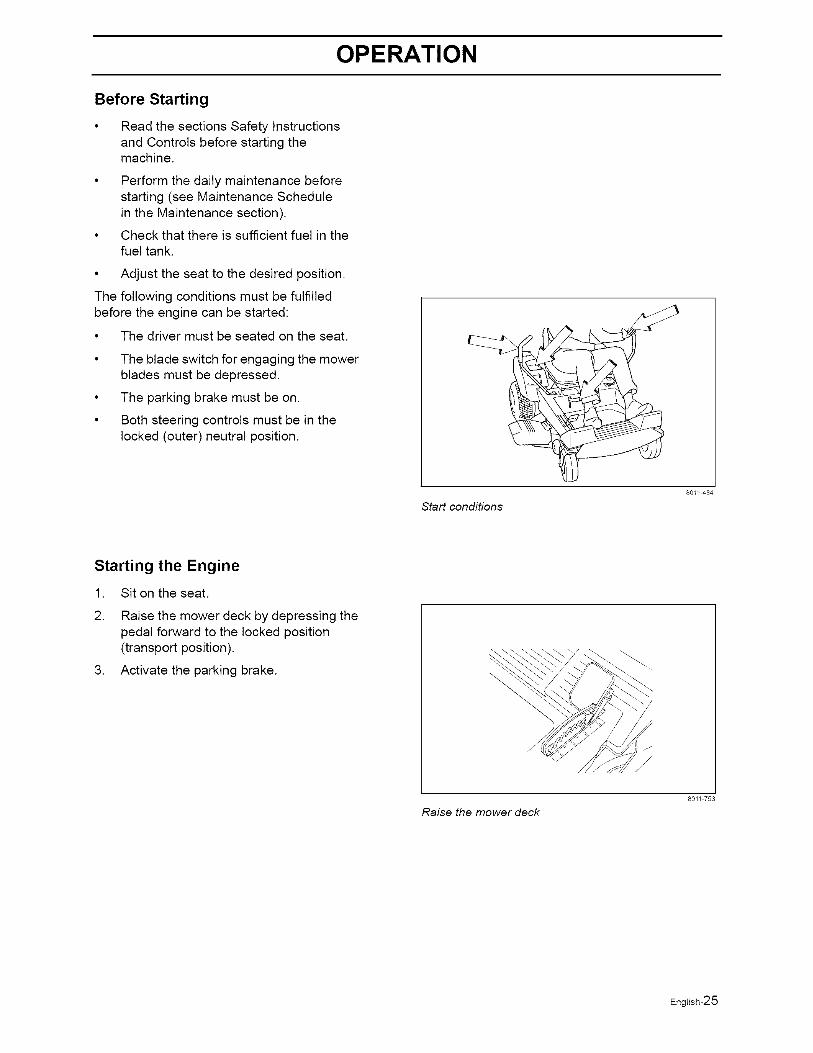
1. Sit on the seat.
2. Raise the mower deck by depressing thepedal forward to the locked position(transport position).
3. Activate the parking brake. \
Raise the mower deck
80// 753
English-25
OPERATION
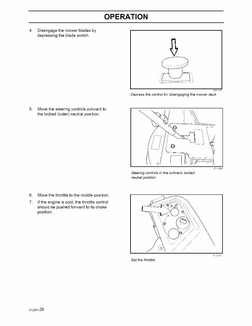
. Disengage the mower blades bydepressing the blade switch.
i ..................
80¸11 668
Depress the control for disengaging the mower deck
5. Move the steering controls outward tothe locked (outer) neutral position.
Steering controls in the outward, locked
neutral position
801/ 489
.
7.
Move the throttle to the middle position.
If the engine is cold, the throttle controlshould be pushed forward to its chokeposition.
Set the throttle
80El 754
English-26
OPERATION
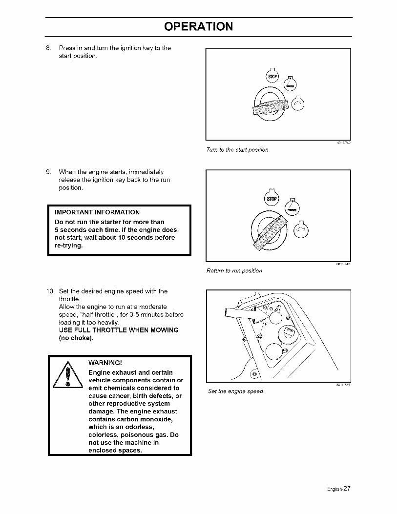
Press in and turn the ignition key to thestart position.
Turn to the start position
80/1 742
When the engine starts, immediatelyrelease the ignition key back to the runposition.
IMPORTANT INFORMATION
Do not run the starter for more than
5 seconds each time. If the engine doesnot start, wait about 10 seconds beforere-trying.
Return to run position
80E/ 743
10. Set the desired engine speed with thethrottle.Allow the engine to run at a moderatespeed, "half throttle", for 3-5 minutes beforeloading it too heavily.USE FULL THROTTLE WHEN MOWING(no choke).
WARNING!
Engine exhaust and certainvehicle components contain oremit chemicals considered to
cause cancer, birth defects, orother reproductive systemdamage. The engine exhaustcontains carbon monoxide,which is an odorless,colorless, poisonous gas. Donot use the machine inenclosed spaces.
Set the engine speed
80/1 754
English-27
OPERATION
To start an engine with a weakbattery
WARNING!
Lead-acid batteries generateexplosive gases. Keep sparks,flame and smoking materialsaway from batteries. Alwayswear eye protection whenaround batteries.
If your battery is too weak to start the engine,it should be recharged. (See "Battery" in theMaintenance Section.
If "jumper cables" are used for emergencystarting, follow this procedure:
IMPORTANT INFORMATION
Your mower is equipped with a 12-voltnegative grounded system. The othervehicle must also be a 12-volt negativegrounded system. Do not use your mowerbattery to start other vehicles.
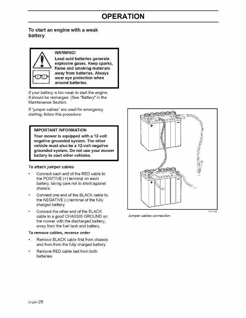
To attach jumper cables
• Connect each end of the RED cable tothe POSITIVE (+) terminal on eachbattery, taking care not to short againstchassis.
• Connect one end of the BLACK cable to
the NEGATIVE (-) terminal of the fullycharged battery.
• Connect the other end of the BLACK
cable to a good CHASSIS GROUND onthe mower with the discharged battery,away from the fuel tank and battery.
To remove cables, reverse order
• Remove BLACK cable first from chassisand then from the fully charged battery.
• Remove RED cable last from bothbatteries.
Jumper cables connection
80// 642
English-28
OPERATION
Running
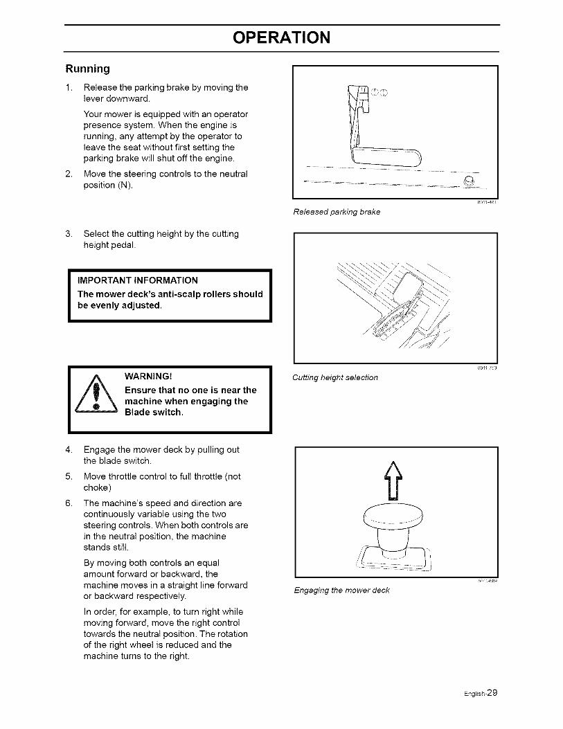
1. Release the parking brake by moving thelever downward.
.
Your mower is equipped with an operatorpresence system. When the engine isrunning, any attempt by the operator toleave the seat without first setting theparking brake will shut off the engine.
Move the steering controls to the neutralposition (N).
3. Select the cutting height by the cuttingheight pedal.
IMPORTANT INFORMATION
The mower deck's anti-scalp rollers shouldbe even ly adj usted.
80/1 481
Released parking brake
\
/
WARNING!
Ensure that no one is near the
machine when engaging theBlade switch.
Cutting height selection
801/ 753
.
5.
6.
Engage the mower deck by pulling outthe blade switch.
Move throttle control to full throttle (notchoke)
The machine's speed and direction arecontinuously variable using the twosteering controls. When both controls arein the neutral position, the machinestands still.
By moving both controls an equalamount forward or backward, themachine moves in a straight line forwardor backward respectively.
In order, for example, to turn right whilemoving forward, move the right controltowards the neutral position. The rotationof the right wheel is reduced and themachine turns to the right.
Engaging the mower deck
80/1 669
English-29
OPERATION
Turning on the spot can be achieved bymoving one control backward (behindthe neutral position) and carefully movingthe other steering control forward from itsneutral position.
Operating on hills
Read the Safety Instructions "Driving onSlopes" in the "Safety Instructions".
WARNING!Do not drive up or down hillswith slopes greater than10 degrees. And do not driveacross any slopes.
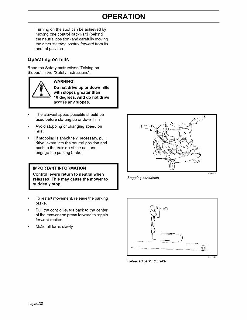
• The slowest speed possible should beused before starting up or down hills.
• Avoid stopping or changing speed onhills.
If stopping is absolutely necessary, pulldrive levers into the neutral position andpush to the outside of the unit andengage the parking brake.
IMPORTANT INFORMATION
Control levers return to neutral whenreleased. This may cause the mower tosuddenly stop.
Stopping conditions
801/ 755
To restart movement, release the parkingbrake.
Pull the control levers back to the centerof the mower and press forward to regainforward motion.
Make all turns slowly.
Released parking brake
80// 481
English-30
OPERATION
Mowing Tips
Observe and flag rocks and other fixedobjects to avoid collisions.
Begin with a high cutting height andreduce it until the desired mowing resultis attained.
The average lawn should be cut to 2 1/2"(64 mm) during the cool season and over3" (76 mm) during the hot months. Forhealthier and better looking lawns, mowoften after moderate growth.
For best cutting performance, grass over6" (15 cm)in height should be mowedtwice. Make the first cut relatively high;the second to the desired height.
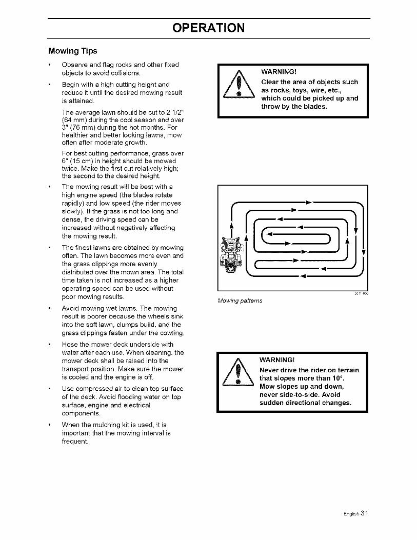
The mowing result will be best with ahigh engine speed (the blades rotaterapidly) and low speed (the rider movesslowly). If the grass is not too long anddense, the driving speed can beincreased without negatively affectingthe mowing result.
The finest lawns are obtained by mowingoften. The lawn becomes more even and
the grass clippings more evenlydistributed over the mown area. The total
time taken is not increased as a higheroperating speed can be used withoutpoor mowing results.
Avoid mowing wet lawns. The mowingresult is poorer because the wheels sinkinto the soft lawn, clumps build, and thegrass clippings fasten under the cowling.
Hose the mower deck underside with
water after each use. When cleaning, themower deck shall be raised into the
transport position. Make sure the moweris cooled and the engine is off.
Use compressed air to clean top surfaceof the deck. Avoid flooding water on topsurface, engine and electricalcomponents.
When the mulching kit is used, it isimportant that the mowing interval isfrequent.
WARNING!
Clear the area of objects suchas rocks, toys, wire, etc.,which could be picked up andthrow by the blades.
fIP.
,,9
,. )
(
Mowing patterns
80// 603
WARNING!
Never drive the rider on terrainthat slopes more than 10°.Mow slopes up and down,never side-to-side. Avoidsudden directional changes.
English-31
OPERATION
Stopping the Engine
Allow the engine to idle a minute in order toattain normal operating temperature beforestopping it, if it has been worked hard. Avoididling the engine for longer periods, as thereis a risk of the spark plugs fouling.
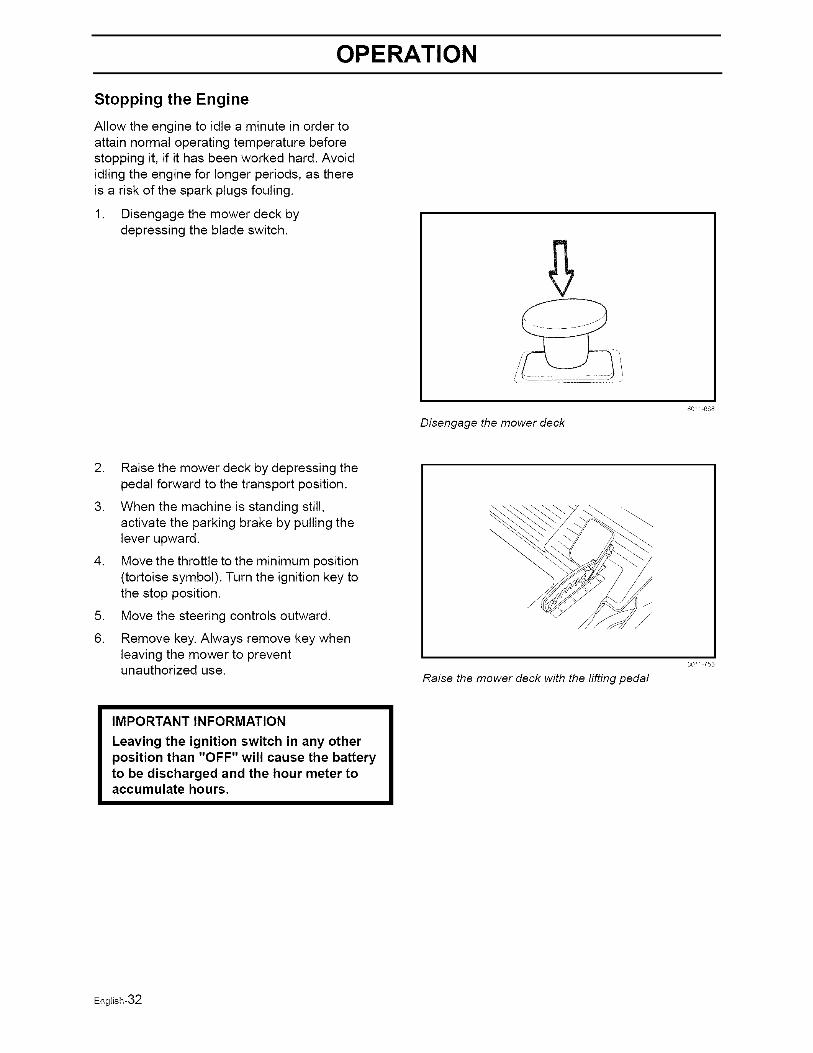
1. Disengage the mower deck bydepressing the blade switch.
Disengage the mower deck
80// 668
2. Raise the mower deck by depressing thepedal forward to the transport position.
3. When the machine is standing still,activate the parking brake by pulling thelever upward.
4. Move the throttle to the minimum position(tortoise symbol). Turn the ignition key tothe stop position.
5. Move the steering controls outward.
6. Remove key. Always remove key whenleaving the mower to preventunauthorized use.
Raise the mower deck with the lifting pedal
80// 753
IMPORTANT INFORMATION
Leaving the ignition switch in any otherposition than "OFF" will cause the batteryto be discharged and the hour meter toaccumulate hours.
English-32
OPERATION
Moving by Hand
WARNING!
No adjustments or maintenanceto be carried out unless:
- the engine stopped,
- the ignition key has removed,
- the parking brake is on.
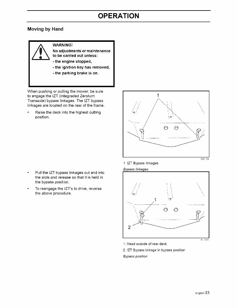
When pushing or pulling the mower, be sureto engage the IZT (lntegraded ZeroturnTransaxle) bypass linkages. The tZT bypasslinkages are located on the rear of the frame.
• Raise the deck into the highest cuttingposition.
/' //
/' //
© ©
\\\
,\\
\
Pull the IZT bypass linkages out and intothe slots and release so that it is held in
the bypass position.
To reengage the IZT's to drive, reversethe above procedure.
80/1 722
1. IZT Bypass linkages
Bypass linkages
/ /
\
i i '\\
© ©
1. Head outside of rear deck
2. IZT Bypass linkage in bypass position
Bypass position
801E 722
English-33
MAINTENANCE
Maintenance
Maintenance Schedule
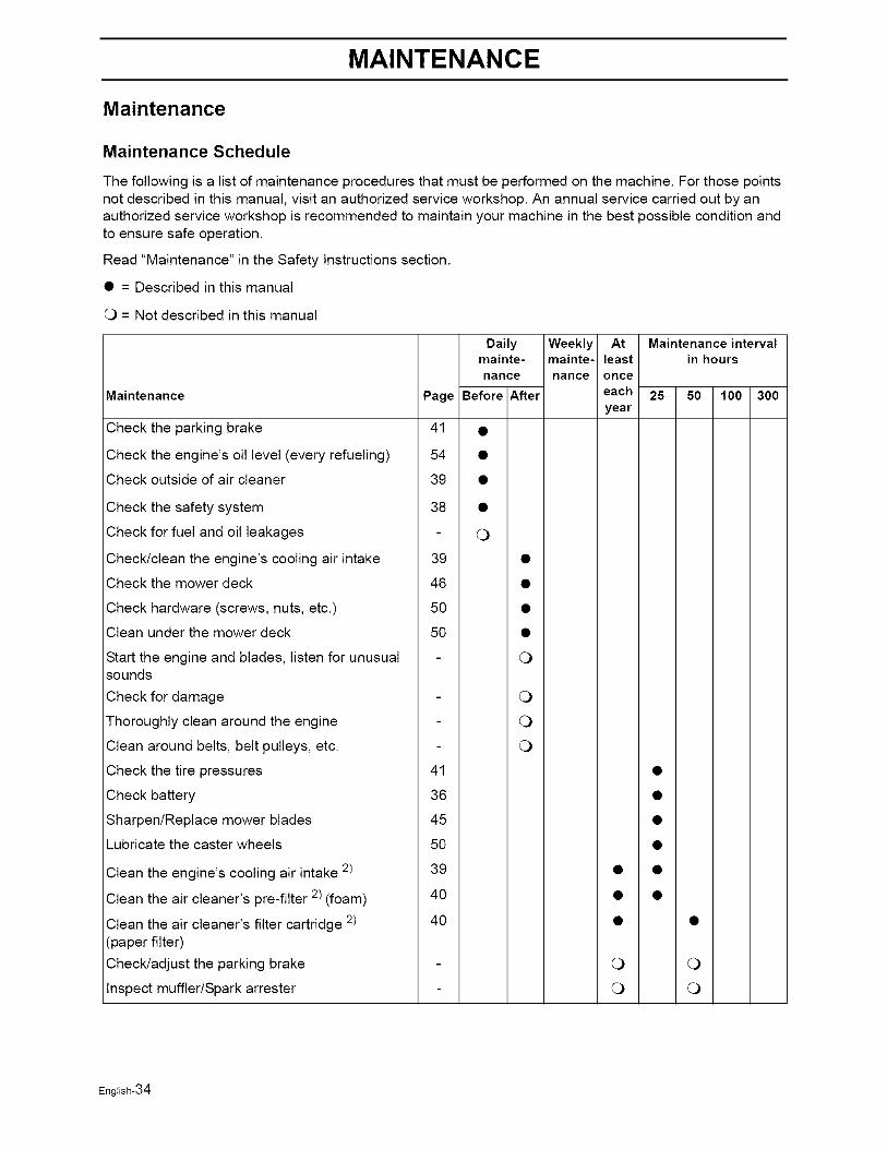
The following is a list of maintenance procedures that must be performed on the machine. For those pointsnot described in this manual, visit an authorized service workshop. An annual service carried out by anauthorized service workshop is recommended to maintain your machine in the best possible condition andto ensure safe operation.
Read "Maintenance" in the Safety Instructions section.
• = Described in this manual
O = Not described in this manual
Maintenance
Daily Weekly Atmainte- mainte- least
nance nance once
Page Before After eachyear
Maintenance intervalin hours
25 50 100 300
Check the parking brake 41
Check the engine's oil level (every refueling) 54
Check outside of air cleaner 39
Check the safety system 38
Check for fuel and oil leakages
Check/clean the engine's cooling air intake 39
Check the mower deck 46
Check hardware (screws, nuts, etc.) 50
Clean under the mower deck 50
Start the engine and blades, listen for unusualsounds
Check for damage
Thoroughly clean around the engine
Clean around belts, belt pulleys, etc.
Check the tire pressures 41
Check battery 36
Sharpen/Replace mower blades 45
Lubricate the caster wheels 50
Clean the engine's cooling air intake 2) 39
Clean the air cleaner's pre-filter 2) (foam) 40
Clean the air cleaner's filter cartridge 2) 40(paper filter)
Check/adjust the parking brake
Inspect muffler/Spark arrester
O
O
O
0
0
0
0
English-34
MAINTENANCE
Maintenance Page
Check/adjust throttle cable 39
Check the condition of belts, belt pulleys, etc. 42
Change the engine oil 1) 52
Replace the engine oil filter 54
Clean/replace the spark plugs 37
Replace the air filter (paper filter) 2) 40
Check the caster wheels (every 200 hours) 50
Clean the cooling fins 2)
Replace the air cleaner's pre-filter 2) (foam) 40
Check/adjust the mower deck 46
Check the engine valve clearance 4)
Perform the 300-hour service 4) 70
Daily Weekly At Maintenance intervalmainte- mainte- least in hours
nance nance once
Before After each 25 50 100 300
year
0 0
0 0
0 0
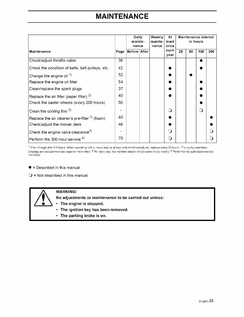
1) First change after 5-8 hours When operating with a heavy load or at high ambient temperatures, replace every 50 hours 2) In dusty conditions,3) 4)cleaning and replacement are required more often For daily use, the machine should be lubricated twice weekly Performed by authorized service
workshop
• = Described in this manual
O = Not described in this manual
WARNING!
No adjustments or maintenance to be carried out unless:
• The engine is stopped.
• The ignition key has been removed.
• The parking brake is on.
English-35
MAINTENANCE
Battery
Your mower is equipped with a maintenance freebattery and does not need servicing. However,periodic charging of the battery with an automotivetype battery charger will extend its life.
• Keep battery and terminals clean.
• Keep battery bolts tight.
• Recharge at 6-10 amperes for 1 hour
To clean battery and terminals
Corrosion and dirt on the battery andterminals can cause the battery to "leak"power.
1. Open terminal access doors.
2. Disconnect BLACK battery cable first, then theRED battery cable and remove the battery fromthe machine.
3. Rinse the battery with plain water and dry.
4. Clean terminals and battery cable endswith wire brush until shiny.
5. Coat terminals with grease or petroleumjelly
6. Reinstall battery.
Always use protective glasseswhen handling the battery.
IMPORTANT INFORMATION
Do not attempt to open or remove capsor covers. Adding or checking level ofelectrolyte is not necessary.
Always use two wrenches for theterminal screws
WARNING!
Do not short battery terminalsby allowing a wrench or anyother object to contact bothterminals at the same time.
Before connecting battery,remove metal bracelets,wristwatch bands, rings, etc.
Positive terminal must beconnected first to preventsparks from accidentalgrounding.
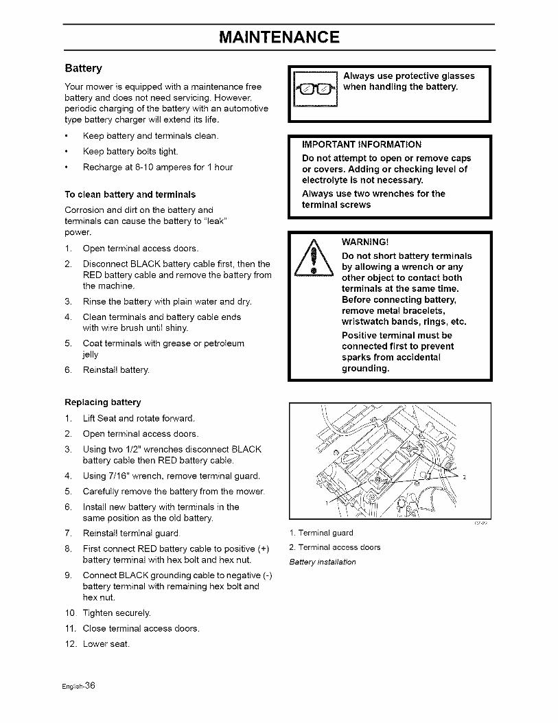
Replacing battery
1. Lift Seat and rotate forward.
2. Open terminal access doors.
3. Using two 1/2" wrenches disconnect BLACKbattery cable then RED battery cable.
4. Using 7/16" wrench, remove terminal guard.
5. Carefully remove the battery from the mower.
6. Install new battery with terminals in thesame position as the old battery.
7. Reinstall terminal guard.
8. First connect RED battery cable to positive (+)battery terminal with hex bolt and hex nut.
9. Connect BLACK grounding cable to negative (-)battery terminal with remaining hex bolt andhex nut.
10. Tighten securely.
11. Close terminal access doors.
12. Lower seat.
1. Terminal guard
2. Terminal access doors
Battery installation
cz 22
English-36
MAINTENANCE
Ignition System
The engine is equipped with an electronicignition system. Only the spark plug requiresmaintenance.
For recommended spark plug, see TechnicalData.
.
2.
3.
Remove the ignition cable boot andclean around the spark plug.
Remove the spark plug with a spark plugsocket wrench.
Check the spark plug. Replace the sparkplug if fouled, the electrodes are burnedand if the insulation is cracked or
damaged. Clean the spark plug with asteel brush if it is to be reused.
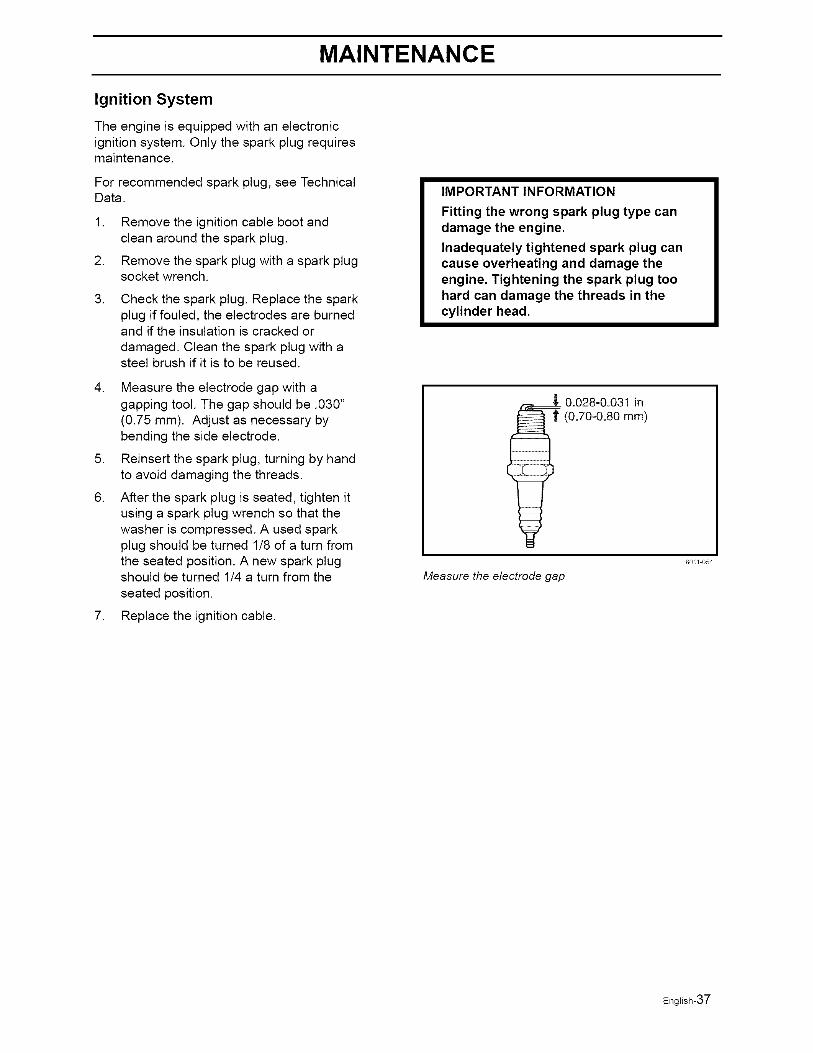
4. Measure the electrode gap with agapping tool. The gap should be .030"(0.75 mm). Adjust as necessary bybending the side electrode.
5. Reinsert the spark plug, turning by handto avoid damaging the threads.
6. After the spark plug is seated, tighten itusing a spark plug wrench so that thewasher is compressed. A used sparkplug should be turned 1/8 of a turn fromthe seated position. A new spark plugshould be turned 1/4 a turn from the
seated position.
7. Replace the ignition cable.
IMPORTANT INFORMATION
Fitting the wrong spark plug type candamage the engine.
Inadequately tightened spark plug cancause overheating and damage theengine. Tightening the spark plug toohard can damage the threads in thecylinder head.
_ 0.028-0.031 in(0.70-0.80 mm)
Measure the electrode gap
801/ 054
English-37
MAINTENANCE
Checking the Safety System
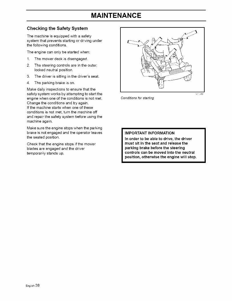
The machine is equipped with a safetysystem that prevents starting or driving underthe following conditions.
The engine can only be started when:
1. The mower deck is disengaged.
2. The steering controls are in the outer,locked neutral position.
3. The driver is sitting in the driver's seat.
4. The parking brake is on.
Make daily inspections to ensure that thesafety system works by attempting to start theengine when one of the conditions is not met.Change the conditions and try again.If the machine starts when one of theseconditions is not met, turn the machine offand repair the safety system before using themachine again.
Make sure the engine stops when the parkingbrake is not engaged and the operator leavesthe seated position.
Check that the engine stops if the mowerblades are engaged and the drivertemporarily stands up.
Conditions for starting
80/1 484
IMPORTANT INFORMATION
In order to be able to drive, the drivermust sit in the seat and release the
parking brake before the steeringcontrols can be moved into the neutral
position, otherwise the engine will stop.
English-38
MAINTENANCE
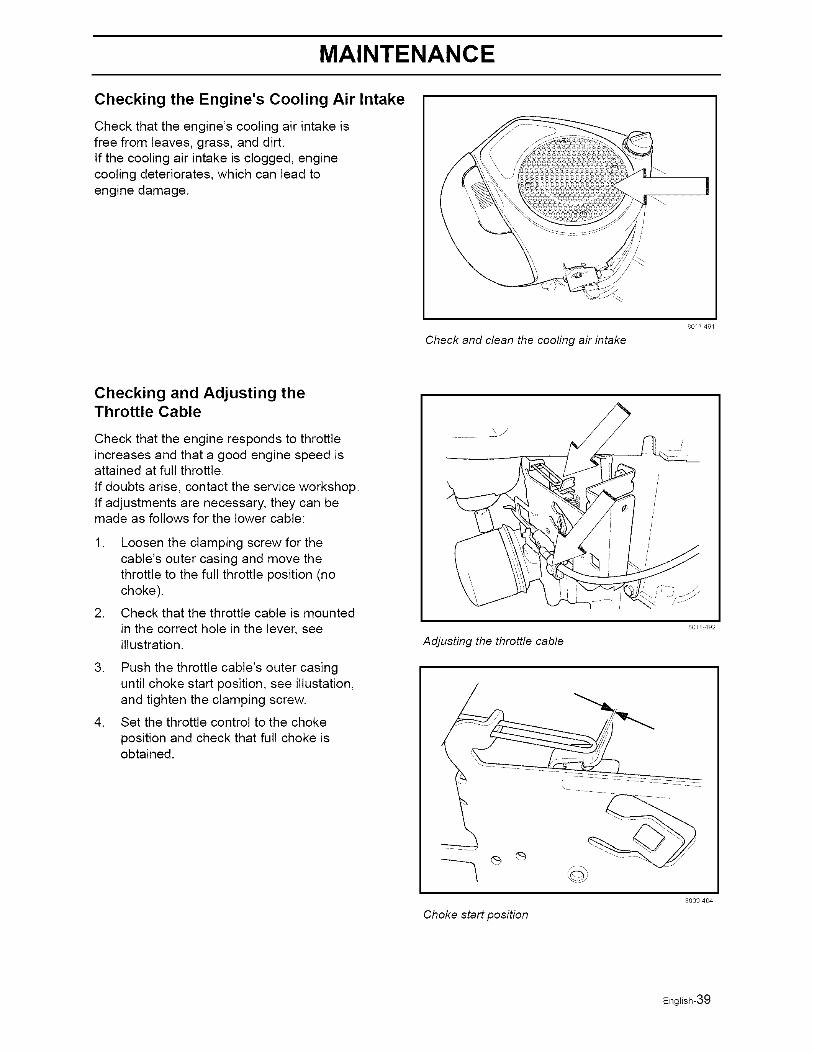
Checking the Engine's Cooling Air Intake
Check that the engine's cooling air intake isfree from leaves, grass, and dirt.If the cooling air intake is clogged, enginecooling deteriorates, which can lead toengine damage.
Check and clean the cooling air intake
80/1 49/
Checking and Adjusting theThrottle Cable
Check that the engine responds to throttleincreases and that a good engine speed isattained at full throttle.
If doubts arise, contact the service workshop.If adjustments are necessary, they can bemade as follows for the lower cable:
1. Loosen the clamping screw for thecable's outer casing and move thethrottle to the full throttle position (nochoke).
2. Check that the throttle cable is mountedin the correct hole in the lever, seeillustration.
3. Push the throttle cable's outer casinguntil choke start position, see illustation,and tighten the clamping screw.
4. Set the throttle control to the choke
position and check that full choke isobtained.
.......... \ J
80EI 492
Adjusting the throttle cable
Choke start position
8009 404
English-39
MAINTENANCE
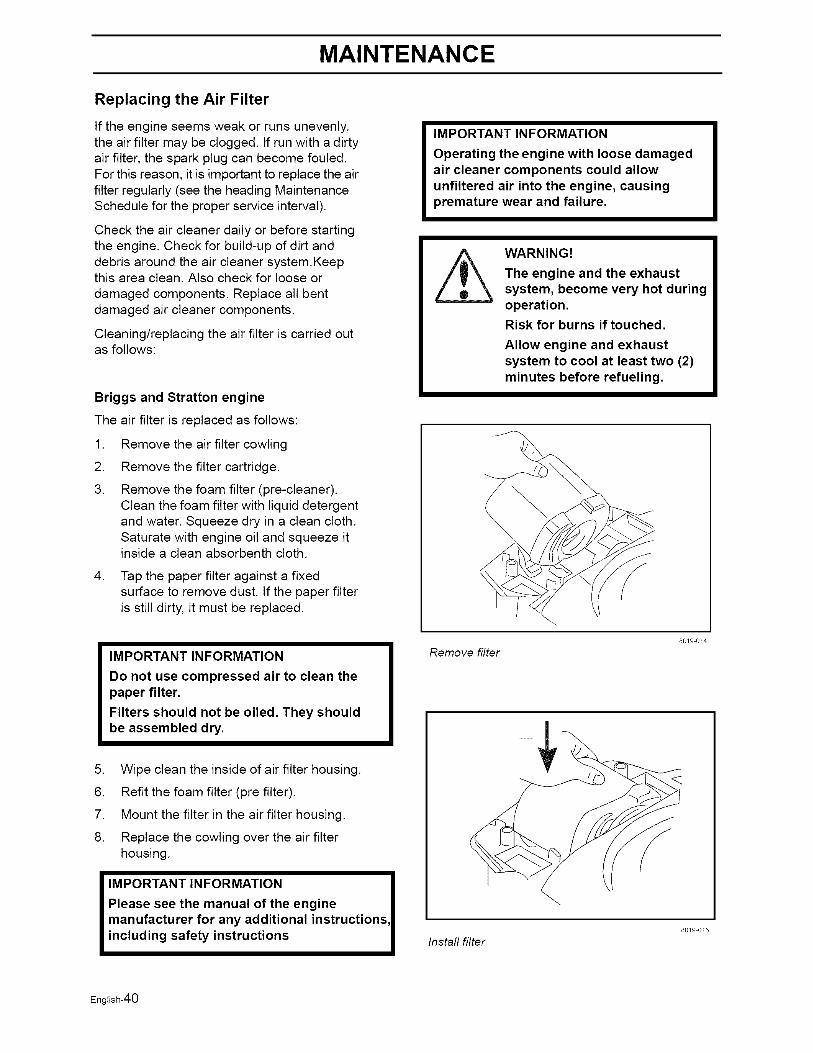
Replacing the Air Filter
If the engine seems weak or runs unevenly,the air filter may be clogged. If run with a dirtyair filter, the spark plug can become fouled.For this reason, it is important to replace the airfilter regularly (see the heading MaintenanceSchedule for the proper service interval).
Check the air cleaner daily or before startingthe engine. Check for build-up of dirt anddebris around the air cleaner system.Keepthis area clean. Also check for loose or
damaged components. Replace all bentdamaged air cleaner components.
Cleaning/replacing the air filter is carried outas follows:
Briggs and Stratton engine
The air filter is replaced as follows:
.
2.
3.
Remove the air filter cowling
Remove the filter cartridge.
Remove the foam filter (pre-cleaner).Clean the foam filter with liquid detergentand water. Squeeze dry in a clean cloth.Saturate with engine oil and squeeze itinside a clean absorbenth cloth.
4. Tap the paper filter against a fixedsurface to remove dust. If the paper filteris still dirty, it must be replaced.
IMPORTANT INFORMATION
Do not use compressed air to clean thepaper filter.
Filters should not be oiled. They shouldbe assembled dry.
5. Wipe clean the inside of air filter housing.
6. Refit the foam filter (pre filter).
7. Mount the filter in the air filter housing.
8. Replace the cowling over the air filterhousing.
IMPORTANT INFORMATION
Please see the manual of the enginemanufacturer for any additional instructions.including safety instructions
IMPORTANT INFORMATION
Operating the engine with loose damagedair cleaner components could allowunfiltered air into the engine, causingpremature wear and failure.
WARNING!
The engine and the exhaustsystem, become very hot duringoperation.
Risk for burns if touched.
Allow engine and exhaustsystem to cool at least two (2)minutes before refueling.
Remove filter80/9 0/4
Install filter80E9 0/5
English-40
MAINTENANCE
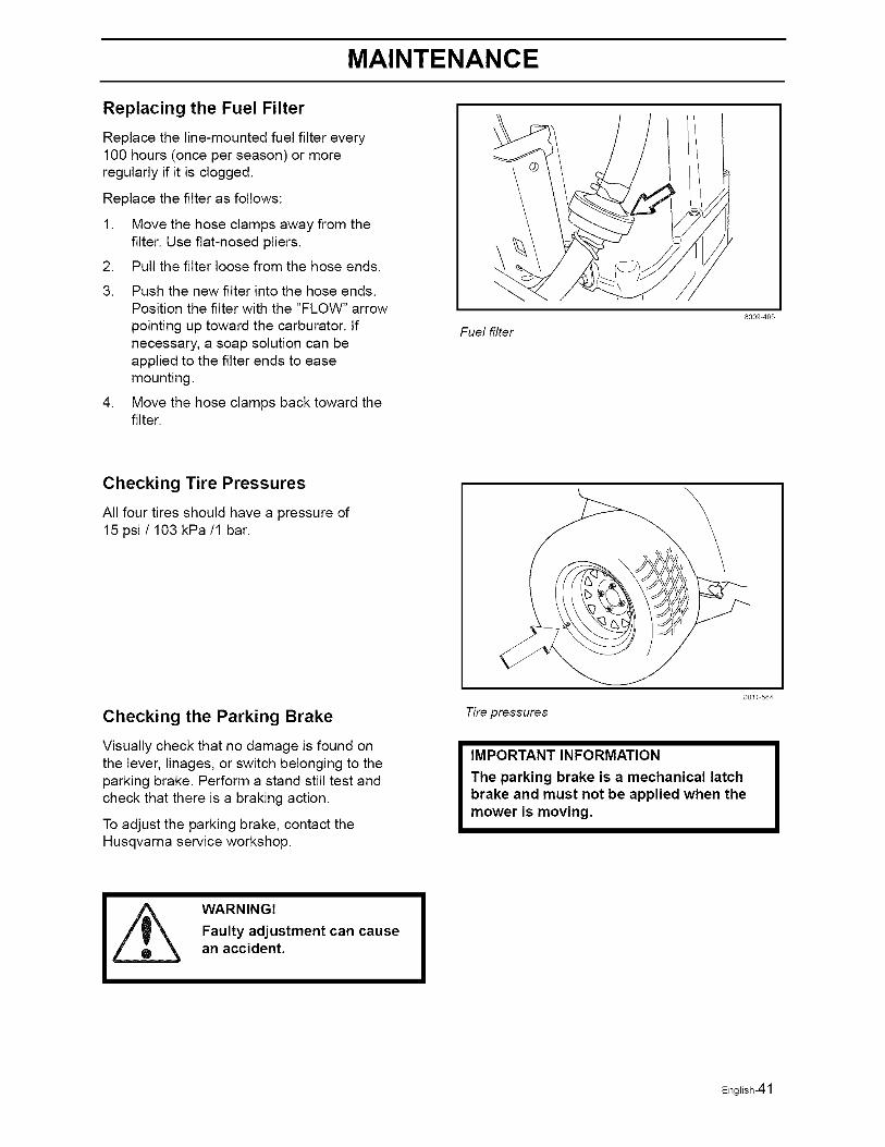
Replacing the Fuel Filter
Replace the line-mounted fuel filter every100 hours (once per season) or moreregularly if it is clogged.
Replace the filter as follows:
1. Move the hose clamps away from thefilter. Use flat-nosed pliers.
2. Pull the filter loose from the hose ends.
3. Push the new filter into the hose ends.Position the filter with the "FLOW" arrow
pointing up toward the carburator. Ifnecessary, a soap solution can beapplied to the filter ends to easemounting.
4. Move the hose clamps back toward thefilter.
Fuel filter
8009 405
Checking Tire Pressures
All four tires should have a pressure of15 psi / 103 kPa/1 bar.
Checking the Parking Brake
Visually check that no damage is found onthe lever, linages, or switch belonging to theparking brake. Perform a stand still test andcheck that there is a braking action.
To adjust the parking brake, contact theHusqvarna service workshop.
Tire pressures
801/ 564
IMPORTANT INFORMATION
The parking brake is a mechanical latchbrake and must not be applied when themower is moving.
WARNING!Faulty adjustment can causean accident.
English-41
MAINTENANCE
Checking the V-belts
WARNING!
No adjustments or maintenance to be carried out unless:
• The engine is stopped.
• The ignition key has been removed.
• The parking brake is on.
Deck belt
V-belts are not adjustable. Replace belts if they begin to slip from wear.
Deck belt removal
WARNING!Idler arm is spring loaded. Havea tight grip on idler arm or
-- ratchet and release slowly.
Park on a level surface. Apply parkingbrake.
• Lower the deck into the lowest cuttingposition
• Disengage belt tension by pushinginward on deck belt idler pulley by handor with a 1/2" drive ratchet placed insquare drive hole on idler arm, While armis pushed inward, remove belt fromstationary idler pulley and release idlerarm slowly until spring force is no longerfelt.
• Remove bolt from idler pulley. This willallow belt to pass by the belt guide.
• Loosen screws from both left and rightplastic belt shield above each mandrelhousing. Remove shields
• Remove any dirt or grass that may haveaccumulated around the cutter housingsand entire deck surface.
• Carefully roll the belt over the top of thecutter housing pulleys.
• Remove the belt from around the electricclutch on the engine shaft.
• The belt can now be removed.
English-42
MAINTENANCE
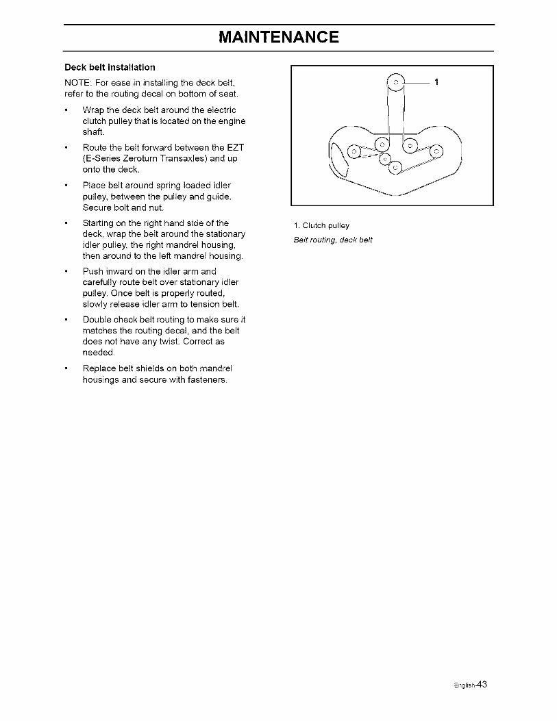
Deck belt installation
NOTE: For ease in installing the deck belt,refer to the routing decal on bottom of seat.
• Wrap the deck belt around the electricclutch pulley that is located on the engineshaft.
Route the belt forward between the EZT
(E-Series Zeroturn Transaxles) and uponto the deck.
Place belt around spring loaded idlerpulley, between the pulley and guide.Secure bolt and nut.
Starting on the right hand side of thedeck, wrap the belt around the stationaryidler pulley, the right mandrel housing,then around to the left mandrel housing.
Push inward on the idler arm and
carefully route belt over stationary idlerpulley. Once belt is properly routed,slowly release idler arm to tension belt.
Double check belt routing to make sure itmatches the routing decal, and the beltdoes not have any twist. Correct asneeded.
Replace belt shields on both mandrelhousings and secure with fasteners.
1. Clutch pulley
Belt routing, deck belt
English-43
MAINTENANCE
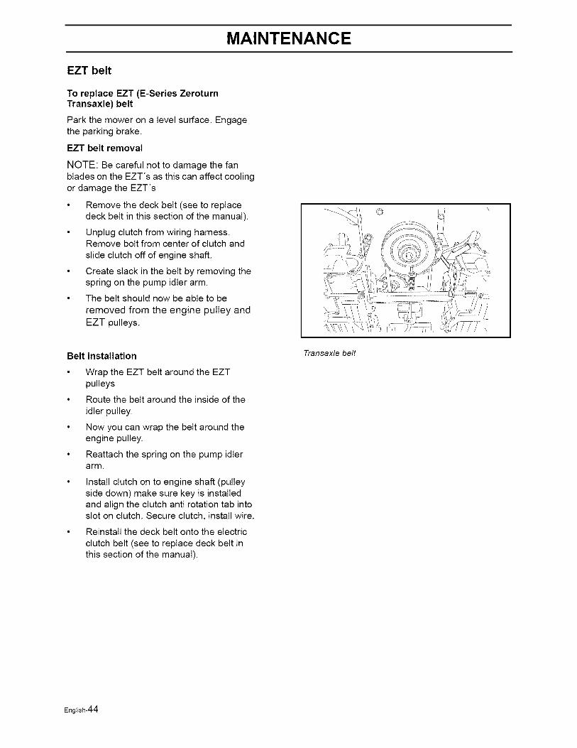
EZT belt
To replace EZT (E-Series ZeroturnTransaxle) belt
Park the mower on a level surface. Engagethe parking brake.
EZT belt removal
NOTE: Be careful not to damage the fanblades on the EZT's as this can affect coolingor damage the EZT's
Remove the deck belt (see to replacedeck belt in this section of the manual).
Unplug clutch from wiring harness.Remove bolt from center of clutch and
slide clutch off of engine shaft.
Create slack in the belt by removing thespring on the pump idler arm.
The belt should now be able to be
removed from the engine pulley andEZT pulleys.
Belt installation
Wrap the EZT belt around the EZTpulleys
Route the belt around the inside of the
idler pulley.
Now you can wrap the belt around theengine pulley.
Reattach the spring on the pump idlerarm.
Install clutch on to engine shaft (pulleyside down) make sure key is installedand align the clutch anti rotation tab intoslot on clutch. Secure clutch, install wire.
Reinstall the deck belt onto the electric
clutch belt (see to replace deck belt inthis section of the manual).
©
Transaxle belt
English-44
MAINTENANCE
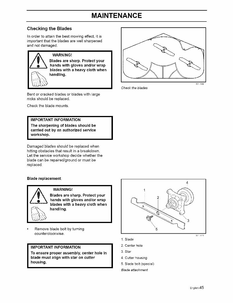
Checking the Blades
In order to attain the best mowing effect, it isimportant that the blades are well sharpenedand not damaged.
Bent or cracked blades or blades with largenicks should be replaced.
Check the blade mounts.
Check the blades
80E/ 604
IMPORTANT INFORMATION
The sharpening of blades should becarried out by an authorized serviceworkshop.
Damaged blades should be replaced whenhitting obstacles that result in a breakdown.Let the service workshop decide whether theblade can be repaired/ground or must bereplaced.
Blade replacement:
WARNING!Blades are sharp. Protect yourhands with gloves and/or wrap
-- blades with a heavy cloth when
_ handling.
Remove blade bolt by turningcounterclockwise.
IMPORTANT INFORMATION
To ensure proper assembly, center hole inblade must align with star on cutterhousing.
1. Blade
2. Center hole
3. Star
4. Cutter housing
5. Blade bolt (special)
Blade attachment
80// 67/
English-45
MAINTENANCE
• Install new or re-sharpened blade withstamped "GRASS SIDE" facing towardsground/grass (down) or "THIS SIDE UP"facing deck and cutter housing.
Install and tighten blade bolt securely.
Torque blade bolt to 27-35 ft/Ib(35-45 Nm).
IMPORTANT INFORMATION
Special blade bolt is heat treated.
Replace with a Husqvarna bolt if required.
Do not use lower grade hardware thanspecified.
Adjusting the Mower Deck
WARNING!
Before performing any service or adjustment checklist:1. Engage the parking brake.2. Place the Blade-switch in the disengaged position.3. Turn ignition switch to "OFF" position and remove the key.4. Make sure the blades and all moving parts have completely stopped.5. Disconnect the spark plug wire from all spark plugs and place the wire where itcannot come in contact with the plug.
WARNING!
Blades are sharp. Protect yourhands with gloves and/or wrapblades with a heavy cloth whenhandling.
Chech the tire pressure before adjustment ofthe mower deck, see "Checking TirePressure" in Maintenance section.
Faulty mower deck adjustment will cause anuneven mowing result.
English-46
MAINTENANCE
To level deck
Adjust the deck while the mower is on a levelsurface. Make sure the tires are inflated to
the correct pressure. See "Technical Data"under Transmission. If tires are under or over
inflated, you can not properly adjust yourdeck.
NOTE: It may be easier to adjust the front liftlinkages by removing the floor pan before anyadjustments are made.
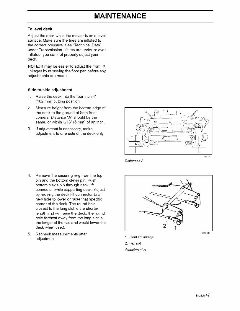
Side-to-side adjustment
1. Raise the deck into the four inch 4"
(102 mm) cutting position.
2. Measure height from the bottom edge ofthe deck to the ground at both frontcorners. Distance "A" should be the
same, or within 3/16" (5 mm) of an inch.
3. If adjustment is necessary, makeadjustment to one side of the deck only
\
Distances A
cz/6
. Remove the securing ring from the toppin and the bottom clevis pin. Pushbottom clevis pin through deck liftconnector while supporting deck. Adjustby moving the deck lift connector to anew hole to lower or raise that specificcorner of the deck. The round hole
closest to the long slot is the shorterlength and will raise the deck, the roundhole farthest away from the long slot isthe longer of the two and would lower thedeck when used.
Recheck measurements after
adjustment.
2
1. Front lift linkage
2. Hex nut
Adjustment A
8011 645
English-47
MAINTENANCE
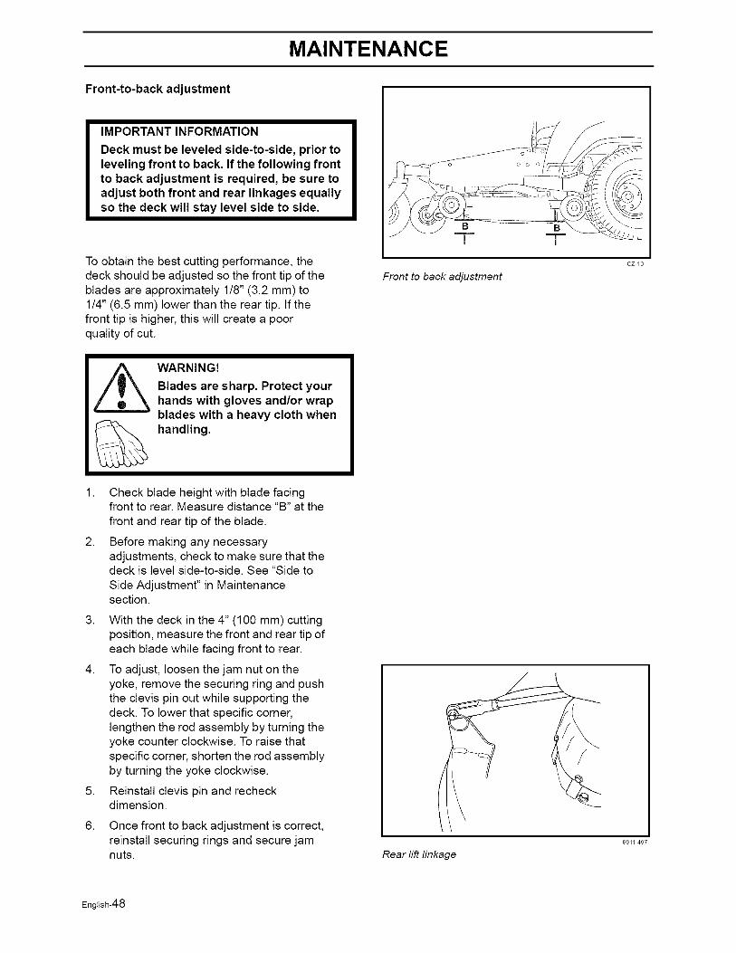
Front-to-back adjustment
IMPORTANT INFORMATION
Deck must be leveled side-to-side, prior toleveling front to back. If the following frontto back adjustment is required, be sure toadjust both front and rear linkages equallyso the deck will stay level side to side.
To obtain the best cutting performance, thedeck should be adjusted so the front tip of theblades are approximately 1/8" (3.2 mm) to1/4" (6.5 mm) lower than the rear tip. If thefront tip is higher, this will create a poorquality of cut.
_ WARNING!Blades are sharp. Protect yourhands with gloves and/or wrapblades with a heavy cloth whenhandling.
/ ....... o J
i--- _ - [
Front to back adjustment
cz/9
1. Check blade height with blade facingfront to rear. Measure distance "B" at the
front and rear tip of the blade.
2. Before making any necessaryadjustments, check to make sure that thedeck is level side-to-side. See "Side to
Side Adjustment" in Maintenancesection.
.
.
6.
With the deck in the 4" (100 mm) cuttingposition, measure the front and rear tip ofeach blade while facing front to rear.
To adjust, loosen the jam nut on theyoke, remove the securing ring and pushthe clevis pin out while supporting thedeck. To lower that specific corner,lengthen the rod assembly by turning theyoke counter clockwise. To raise thatspecific corner, shorten the rod assemblyby turning the yoke clockwise.
Reinstall clevis pin and recheckdimension.
Once front to back adjustment is correct,reinstall securing rings and secure jamnuts.
/
Rearl@linkage
8011 497
English-48
MAINTENANCE
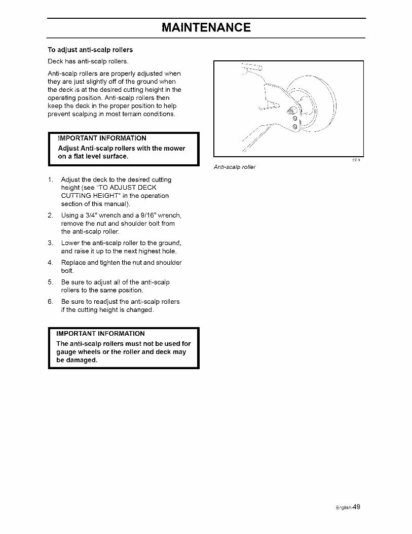
To adjust anti-scalp rollers
Deck has anti-scalp rollers.
Anti-scalp rollers are properly adjusted whenthey are just slightly off of the ground whenthe deck is at the desired cutting height in theoperating position. Anti-scalp rollers thenkeep the deck in the proper position to helpprevent scalping in most terrain conditions.
IMPORTANT INFORMATION
Adjust Anti-scalp rollers with the moweron a flat level surface.
.
.
4.
5.
6.
Adjust the deck to the desired cuttingheight (see "TO ADJUST DECKCUTTING HEIGHT" in the operationsection of this manual).
Using a 3/4" wrench and a 9/16" wrench,remove the nut and shoulder bolt fromthe anti-scalp roller.
Lower the anti-scalp roller to the ground,and raise it up to the next highest hole.
Replace and tighten the nut and shoulderbolt.
Be sure to adjust all of the anti-scalprollers to the same position.
Be sure to readjust the anti-scalp rollersif the cutting height is changed.
\
®
Anti-scalp roller
cz 9
IMPORTANT INFORMATION
The anti-scalp rollers must not be used forgauge wheels or the roller and deck maybe damaged.
English-49
MAINTENANCE
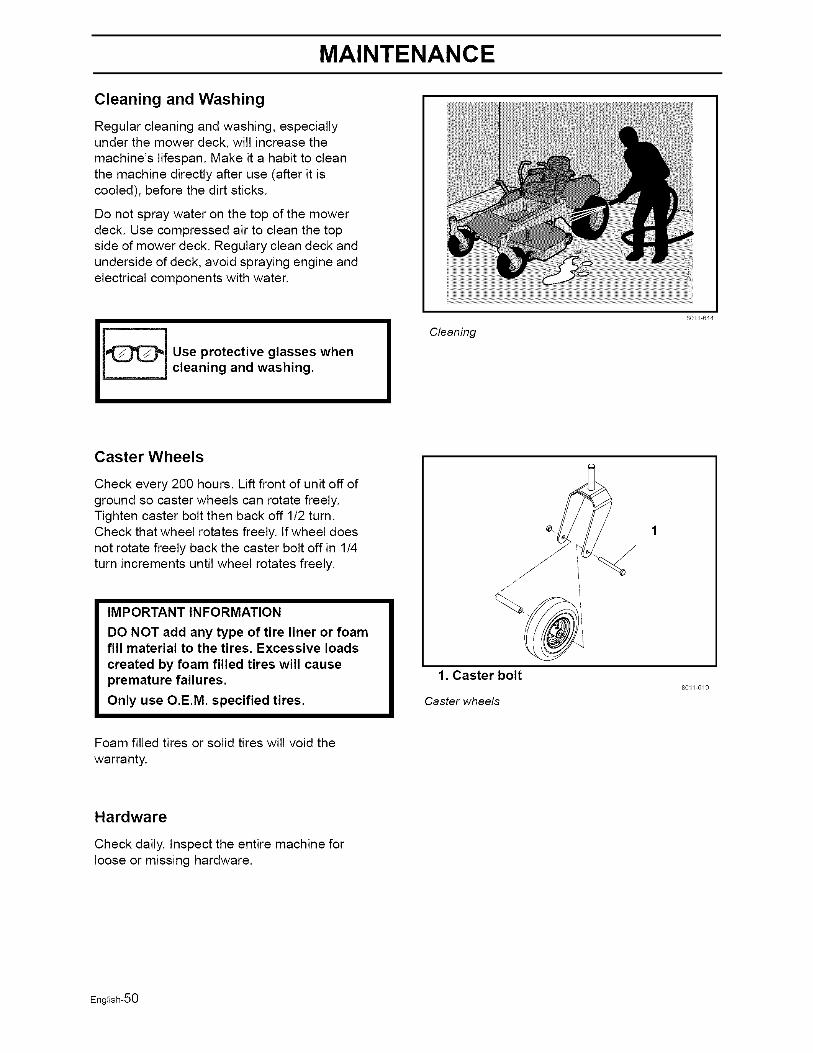
Cleaning and Washing
Regular cleaning and washing, especiallyunder the mower deck, will increase themachine's lifespan. Make it a habit to cleanthe machine directly after use (after it iscooled), before the dirt sticks.
Do not spray water on the top of the mowerdeck. Use compressed air to clean the topside of mower deck. Regulary clean deck andunderside of deck, avoid spraying engine andelectrical components with water.
Use protective glasses whencleaning and washing.
80EI 644
Cleaning
Caster Wheels
Check every 200 hours. Lift front of unit off ofground so caster wheels can rotate freely.Tighten caster bolt then back off 1/2 turn.Check that wheel rotates freely. If wheel doesnot rotate freely back the caster bolt off in 1/4turn increments until wheel rotates freely.
IMPORTANT INFORMATION
DO NOT add any type of tire liner or foamfill material to the tires. Excessive loadscreated by foam filled tires will causepremature failures.
Only use O.E.M. specified tires.
1. Caster bolt
Caster wheels
801/ 6/9
Foam filled tires or solid tires will void the
warranty.
Hardware
Check daily. Inspect the entire machine forloose or missing hardware.
English-50
LUBRICATION
Lubrication
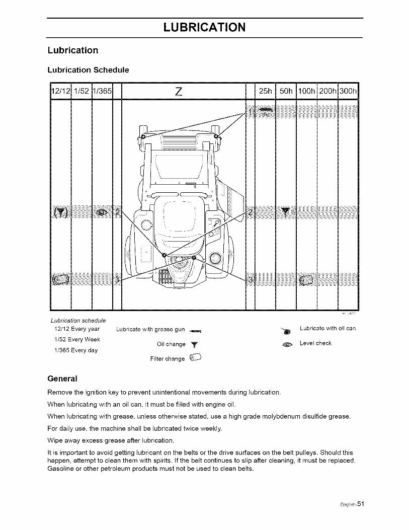
Lubrication Schedule
2/12 1/52 1/365 25h 50h lOOh 200h 300h
80/1 673
Lubrication schedule
12/12 Every year Lubricate with grease gun _ --_ Lubricate with oil can
1/52 Every WeekOil change "_r _ Level check
1/365 Every day
Filter change
General
Remove the ignition key to prevent unintentional movements during lubrication.
When lubricating with an oil can, it must be filled with engine oil.
When lubricating with grease, unless otherwise stated, use a high grade molybdenum disulfide grease.
For daily use, the machine shall be lubricated twice weekly.
Wipe away excess grease after lubrication.
It is important to avoid getting lubricant on the belts or the drive surfaces on the belt pulleys. Should thishappen, attempt to clean them with spirits, tf the belt continues to slip after cleaning, it must be replaced.Gasoline or other petroleum products must not be used to clean belts.
English-51
LUBRICATION
Lubricating the Cables
If possible, grease both ends of the cables and move the controls to end stop positions when lubricating.Refit the rubber covers on the cables after lubrication. Cables with sheaths will bind if they are notlubricated regularly, tf a cable binds, it can disrupt operation.
If a cable binds, remove the cable and hang it vertically. Lubricate it with light engine oil until the oil beginsto escape from the bottom.
Tip: Fill a small plastic bag with oil and tape it so that it seals against the sheath and allow the cable to hangvertically from the bag overnight. If you do not succeed in lubricating the cable, it must be replaced.
Lubricating in Accordance with theLubrication Schedule
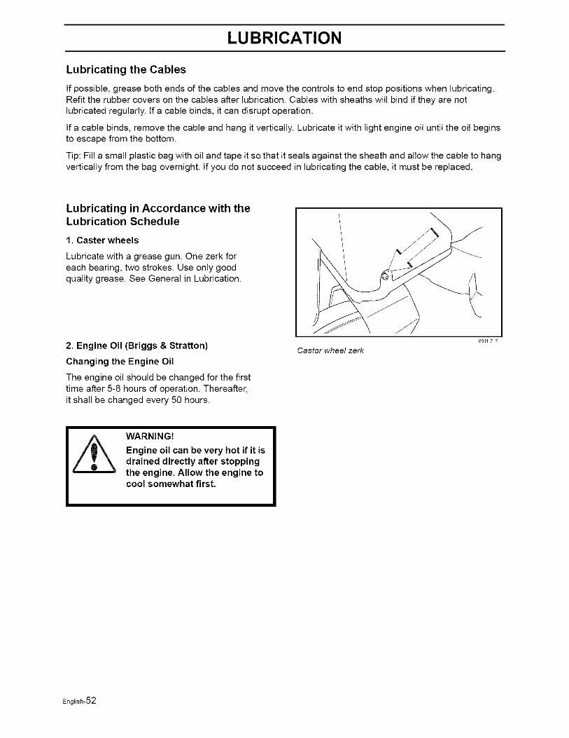
1. Caster wheels
Lubricate with a grease gun. One zerk foreach bearing, two strokes. Use only goodquality grease. See General in Lubrication.
2. Engine Oil (Briggs & Stratton)
Changing the Engine Oil
The engine oil should be changed for the firsttime after 5-8 hours of operation. Thereafter,it shall be changed every 50 hours.
Castor wheel zerk
801/ 7/7
WARNING!
Engine oil can be very hot if it isdrained directly after stoppingthe engine. Allow the engine tocool somewhat first.
English-52
LUBRICATION
1. Place the machine on a flat surface.
2. Remove the yellow cap and fit a hose tothe drain valve.
IMPORTANT INFORMATION
Used engine oil is a health hazard andmust not be disposed of on the ground orin nature; it should always be disposedof at a workshop or appropriate disposallocation.
Avoid skin contact; wash with soap andwater in case of spills.
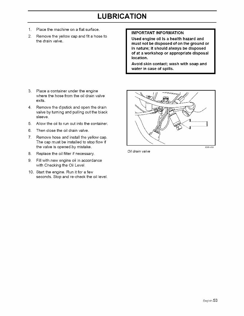
3. Place a container under the enginewhere the hose from the oil drain valveexits.
4. Remove the dipstick and open the drainvalve by turning and pulling out the blacksleeve.
5. Allow the oil to run out into the container.
6. Then close the oil drain valve.
7. Remove hose and install the yellow cap.The cap must be installed to stop flow ifthe valve is opened by mistake.
8. Replace the oil filter if necessary.
9. Fill with new engine oil in accordancewith Checking the Oil Level.
10. Start the engine. Run it for a fewseconds. Stop and re-check the oil level.
Off drain valve
8011 499
English-53
LUBRICATION
Checking the oil level
Check the oil level in the engine when themachine is standing level and the engine isstopped.
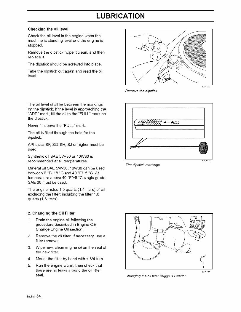
Remove the dipstick, wipe it clean, and thenreplace it.
The dipstick should be screwed into place.
Take the dipstick out again and read the oillevel.
801/ 500
Remove the dipstick
The oil level shall lie between the markingson the dipstick. If the level is approaching the"ADD" mark, fill the oil to the "FULL" mark onthe dipstick.
Never fill above the "FULL" mark.
The oil is filled through the hole for thedipstick.
API class SE SG, SH, SJ or higher must beused
Synthetic oil SAE 5W-30 or 10W30 isrecommended at all temperatures.
Mineral oil SAE 5W-30, 10W30 can be usedbetween 0 °F/-18 °C and 40 °F/+5 °C. At
temperature above 40 °F/+5 °C single gradeSAE 30 must be used.
The engine holds 1.5 quarts (1.4 liters) of oilexcluding the filter; including the filter 1.6quarts (1.5 liters).
( uL,
The dipstick markings
8009159
2. Changing the Oil Filter
1. Drain the engine oil following theprocedure described in Engine Oil/Change Engine Oil section.
2. Remove the oil filter, tf necessary, use afilter remover.
3. Wipe new, clean engine oil on the seal ofthe new filter.
4. Mount the filter by hand with + 3/4 turn.
5. Run the engine warm, then check thatthere are no leaks around the oil filterseal. Changing the off filter Briggs & Stratton
80/1 707
English-54
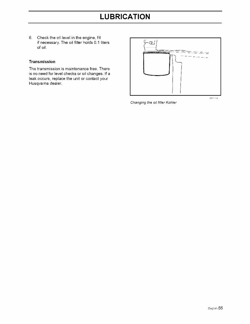
LUBRICATION
6. Check the oil level in the engine, fillif necessary. The oil filter holds 0.1 litersof oil.
Transmission
The transmission is maintenance free. There
is no need for level checks or oil changes. If aleak occurs, replace the unit or contact yourHusqvarna dealer.
Changing the oil filter Kohler
801/ 739
English-55

TROUBLE SHOOTING GUIDE
Trouble Shooting Guide
Problem Cause
The engine will not start. • The blade switch is engaged.
The steering controls are not locked in theneutral position.
• The driver is not sitting in the driver's seat.
• The parking brake is not activated.
• The battery is dead.
• Contamination in the carburetor or fuel line.
• The fuel supply is closed or the tapfor the fuel tanks is in the wrong position.
• Clogged fuel filter or fuel line.
The starter motor does not turn the engine over. • Dead battery.
• Poor contacts on the battery terminalcable connections.
• Fuse blown.
• Ignition system faulty.
• Fault in the starter motor safety circuit.See Checking the Safety System in the
Maintenance section.
The engine runs rough. Faulty carburetor.
The choke control is pulled out with a warm engine.
Defective valves.
Defective piston, cylinder, piston ring, orcylinder head seal.
The cylinder head bolts are loose.
Clogged fuel filter or jet.
Clogged ventilation valve on the fuel cap.
Fuel tank nearly empty.
Defective spark plug.
The spark plug is loose.
Defective ignition cable.
Defective spark plug electrode.
Defective spark plug connection.
Rich fuel mixture or fuel-air mixture.
English-56

TROUBLE SHOOTING GUIDE
• Wrong fuel type.
• Water in the fuel.
• Clogged air filter.
The engine seems weak. • Clogged air filter.
• Defective spark plug.
• Carburetor incorrectly adjusted.
The engine overheats. Clogged air intake or cooling fins.
Engine overloaded.
Poor ventilation around engine.
Defective engine speed regulator.
Soot in the combustion chamber.
Too little or no oil in the engine.
Defective spark plug.
Pre-ignition incorrect.
Battery not charging. • Poor contact with battery terminalcable connectors.
The machine moves slowly, unevenly,
or not at all.
• Parking brake on.
• Bypass valve on pump open.
• Drive belt for the transmission gears slack orhas come off.
Mower deck not engaging. • Drive belt for the mower deck has come loose.
• Contact for the electromagnetic couplinghas loosened.
• The blade switch is faulty or has come loose,from the cable contact.
• The fuse has blown.
English-57

TROUBLE SHOOTING GUIDE
Uneven mowing results. Different air pressure in the tires on the left andright sides.
• Bent blades.
• The suspending for the mower deckis uneven.
• The blades are blunt.
• Driving speed too high.
• The grass is too long.
• Grass collected under the mower deck.
The machine vibrates. • The blades are loose.
• The blades are incorrectly balanced.
• The engine is loose.
English-58
STORAGE
Storage
Winter Storage
At the end of the mowing season, the machineshould be readied for storage (or if it will not be inuse for longer than 30 days). Fuel allowed tostand for long periods of time (30 days or more)can leave sticky residues that can foul thecarburetor and disrupt engine function.
Fuel stabilizers are an acceptable option asregards to the sticky residues that can occurduring storage.
Add stabilizer to the fuel in the tank or in the
storage container. Always use the mixing ratiosspecified by the manufacturer of the stabilizer.Run the engine for at least 10 minutes afteradding the stabilizer so that it reaches thecarburetor. Do not empty the fuel tank and thecarburetor if you have added stabilizer.
WARNING!
Never store an engine with fuelin the tank indoors or in poorlyventilated spaces where fuelvapor can come in contact withopen flames, sparks, or a pilotlight such as in a boiler, hotwater tank, clothes drier, etc.Handle the fuel with care. It is
very flammable and carelessuse can cause serious personalinjury and property damage.Drain the fuel into an approvedcontainer outdoors and faraway from open flame. Neveruse gasoline for cleaning. Usea degreaser and warm waterinstead.
To ready the machine for storage, follow thesesteps:
1. Thoroughly clean the machine, especiallyunder the mower deck. Touch up damage tothe paint and spray a thin layer of oil on theunderside of the mower deck to avoidcorrosion.
2. Inspect the machine for worn or damagedparts and tighten any nuts or screws that mayhave become loose.
.
4.
Change the engine oil; dispose of properly.
Empty the fuel tanks or add a fuel stabilizer.Start the engine and allow it to run until thecarburetor is drained of fuel or the stabilizerhas reached the carburetor.
5. Remove the spark plug and pour about atablespoon of engine oil into the cylinder.Turn over the engine so that the oil is evenlydistributed and then refit the spark plug.
6. Lubricate all grease zerks, joints, and axles.
7. Remove the battery. Clean, charge, and storethe battery in a cool place, but protect it fromdirect cold.
8. _ore the machine in a clean, dry place andcover it for extra protection.
Service
When ordering spare parts, please specify thepurchase year, model, type, and serial number.
Always use genuine Husqvarna spare parts.
An annual check-up at an authorized serviceworkshop is a good way to ensure that yourmachine performs its best the following season.
English-59
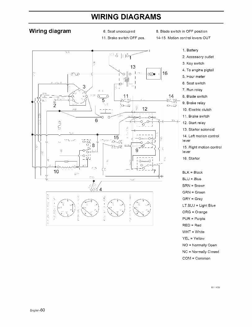
WIRING DIAGRAMS
Wiring diagram 6. Seat unoccupied
11. Brake switch OFF pos.
8. Blade switch in OFF position
14-15. Motion control levers OUT
ill,J
1. Battery
2. Accessory outlet
3. Key switch
4. To engine pigtail16
5. Hour meter
6. Seat switch
7. Run relay
14 8. Blade switch
I'_c_ 9. Brake relayLO---ZL>_10. Electric clutch
1 1. Brake switch
12. Start relay
13. Starter solenoid
14. Left motion control
lever
15. Right motion controllever
16. Starter
BLK = Black
BLU = Blue
BRN = Brown
GRN = Green
GRY = Grey
LT.BLU = Light Blue
ORG = Orange
PUR = Purple
RED = Red
WriT = White
YEL = Yellow
NO = Normally Open
NC = Normally Closed
COM = Common
801/ 650
English-60

TECHNICAL DATA
Technical DataTechnical Data
Z4218 Z4219
Engine
Manufacturer
Type
Power
Lubrication
Oil capacity excl filter
Oil capacity incl filter
Engine oil
(See viscocity digram)
Kohler Briggs and Stratton
Courage Intek Single
18 hp / 13.4kW 19 hp / 14.2kW
Pressure with oil filter
1.6 qt / 1.5 liter 1.5 qt / 1.4 liter
1.7 qt / 1.6 liter 1.6 qt / 1.5 liter
SAE 10W30, 5W20, SAE 5W30, 10W30 Synt.5W30 SAE 30 Mineral
API SF-SJ API SF-SJ
Fuel Min 85 octane unleaded Min 85 octane unleaded
(Max methanol 0%, max (Max methanol 0%, max
ethanol 10%, Max MTBE ethanol 10%, Max MTBE
15%) 15%)
Fuel tank capacity 3 gallon / 11.4 liters 3 gallon / 11.4 liters
Spark plugs / gap Champion RCl 2YC Champion RC12YC.030" 1 0.75 mm .030" / 0.75 mm
Cooling Air cooled Air cooled
Air filter Standard Standard
Alternator 12V 12 V 9 A
Starter Electric Electric
Transmission
Transmission Hydrostatic transaxles
Speed and direction controls Dual levers, foam gripped
Speed forward 0-6 mph / 0-9.7 km/h 0-6 mph / 0-9.7 km/h
Speed reverse 0-3.5 mph / 0-5.6 km/h 0-3.5 mph / 0-5.6 km/h
Brakes Mechanical parking brake
Front caster tires, Smooth 11x3.5-5, 4 ply 11x3.5-5, 4 plytread
Rear tires, Turf pneumatic 18x9.5-8 18x9.5-8
Tire pressure, front and rear 15PSI/103kPa/lbar 15PSI/103kPa/lbar
English-61

TECHNICAL DATA
Z4218 Z4219
Equipment
Cutting width 42"/107cm 42"/107cm
Cutting height 1.5"- 4" / 3.8 - 10.2 cm 1.5"- 4"/3.8 - 10.2 cm
Uncut circle 0 0
Number of blades 2 2
Blade length 21" / 533 mm 21" / 533 mm
Nose rollers No No
Sprung standard seat Standard Standard
Hinged armrests No No
Hour meter Standard Standard
Blade engagement 85 ft/Ib Warner 85 ft/Ib Warner
Deck construction 12 gauge, stamped steel 12 gauge, stamped steel
Productivity
Productivity 2.6 acres/h 10530 m2/h 2.6 acres/h 10530 m2/h
Overall dimensions
Weight 485 Ibs/220 kg 485 Ibs/220 kg
Base machine length 72"/183 cm 72"/183 cm
Base machine width 43"/109 cm 43" / 109 cm
Base machine height 41"/104 cm 41"/104 cm
Overall width, Chute up 43" / 109 cm 43"/109 cm
Overall width, Chute down 52"/132 cm 52"/132 cm
English-62
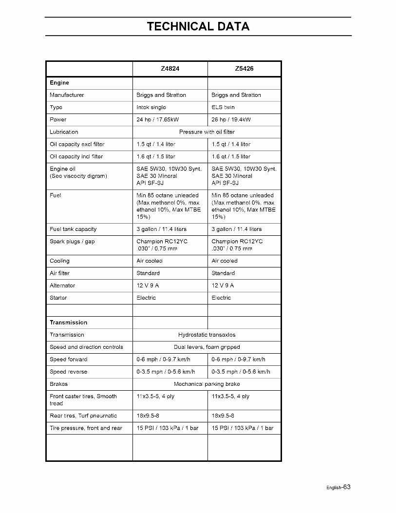
TECHNICAL DATA
Z4824 Z5426
Engine
Manufacturer
Type
Power
Lubrication
Oil capacity excl filter
Oil capacity incl filter
Engine oil
(See viscocity digram)
Briggs and Stratton Briggs and Stratton
Intek single ELS twin
24 hp/17.65kW 26 hpi 19.4kW
Pressure with oil filter
1.5 qt / 1.4 liter 1.5 qt / 1.4 liter
1.6 qt / 1.5 liter 1.6 qt / 1.5 liter
SAE 5W30, 10W30 Synt. SAE 5W30, 10W30 Synt.SAE 30 Mineral SAE 30 Mineral
API SF-SJ API SF-SJ
Fuel Min 85 octane unleaded Min 85 octane unleaded
(Max methanol 0%, max (Max methanol 0%, max
ethanol 10%, Max MTBE ethanol 10%, Max MTBE
15%) 15%)
Fuel tank capacity 3 gallon / 11.4 liters 3 gallon / 11.4 liters
Spark plugs /gap Champion RC12YC Champion RC12YC.030" / 0.75 mm .030" / 0.75 mm
Cooling Air cooled Air cooled
Air filter Standard Standard
Alternator 12 V 9 A 12 V 9 A
Starter Electric Electric
Transmission
Transmission Hydrostatic transaxles
Speed and direction controls Dual levers, foam gripped
Speed forward 0-6 mph / 0-9.7 kmih 0-6 mph / 0-9.7 km/h
Speed reverse 0-3.5 mph / 0-5.6 kmih 0-3.5 mph / 0-5.6 km/h
Brakes Mechanical parking brake
Front caster tires, Smooth 11x3.5-5, 4 ply 11x3.5-5, 4 plytread
Rear tires, Turf pneumatic 18x9.5-8 18x9.5-8
Tire pressure, front and rear 15PSI/103kPa/lbar 15PSIi103kPa/1 bar
English-63
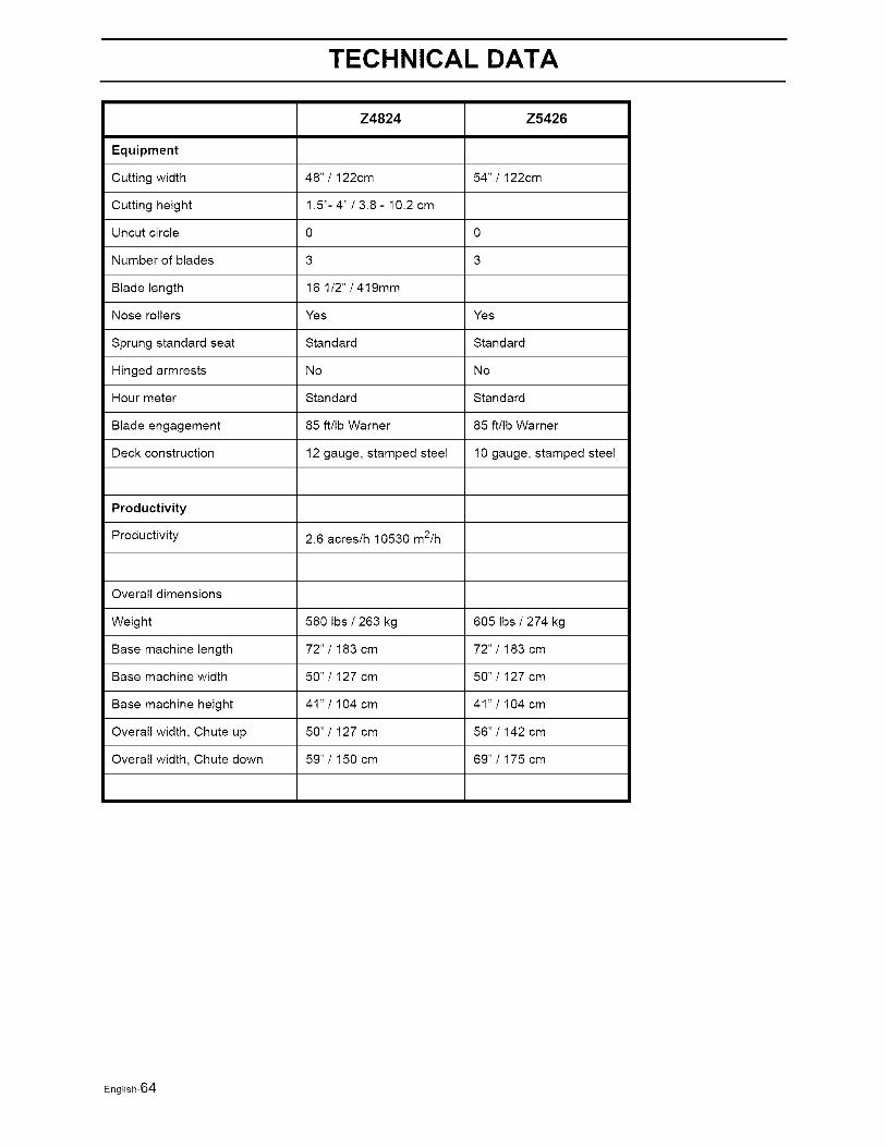
TECHNICAL DATA
Z4824 Z5426
Equipment
Cutting width 48"/122cm 54"/122cm
Cutting height 1.5"- 4" / 3.8 - 10.2 cm
Uncut circle 0 0
Number of blades 3 3
Blade length 16 1/2" / 419mm
Nose rollers Yes Yes
Sprung standard seat Standard Standard
Hinged armrests No No
Hour meter Standard Standard
Blade engagement 85 ft/Ib Warner 85 ft/Ib Warner
Deck construction 12 gauge, stamped steel 10 gauge, stamped steel
Productivity
Productivity 2.6 acres/h 10530 m2/h
Overall dimensions
Weight 580 Ibs / 263 kg 605 Ibs / 274 kg
Base machine length 72"/183 cm 72"1 183 cm
Base machine width 50"/127 cm 50"/127 cm
Base machine height 41"/104 cm 41"/104 cm
Overall width, Chute up 50"1 127 cm 56" / 142 cm
Overall width, Chute down 59"/150 cm 69" / 175 cm
English-64

TECHNICAL DATA
Accessories
Head lights
BioClip attachment (Mulch clip)
Collection system
Torque Specifications
-Engine crankshaft bolt
-Deck pulley bolts
-Lug nuts
-Blade bolt
-Standard IA" fasteners
-Standard 5/16" fasteners
-Standard 3/8" fasteners
-Standard 7/16" fasteners
-Standard ½" fasteners
50 ft/Ib (67 Nm)
45 ft/Ib (61 Nm)
75 ft/Ib (100 Nm)
27-35 ft/Ib (35-45 Nm)
9 ft/Ib (12 Nm)
18 ft/Ib (25 Nm)
33 ft/Ib (44 Nm)
52 ft/Ib (70 Nm)
80 ft/Ib (110 Nm)
When this product is worn out and no longer used, it shall be returned to the reseller or other party forrecycling.
In order to implement improvements, specifications and designs can be altered without priornotification.
Note that no legal demands can be placed based on the information contained in theseinstructions.
Use only original parts for repairs. The use of other parts voids the warranty.
Do not modify or install non-standard equipment to the unit without consent from themanufacturer. Modifications to the unit may cause unsafe operation or damage the unit.
English-65

CONFORMITY CERTIFICATES
Conformity Certificates
USA requirements
Labels are placed on the engine and/or in the engine compartment stating that the machine will fulfill therequirements. This is also applicable to special requirements for any of the states, (Californian emissionrules etc.). Do not remove any of these labels. Certificates can also be supplied with the machine atdelivery or written in the Engine manual. Take care of them as valuable documents.
English-66
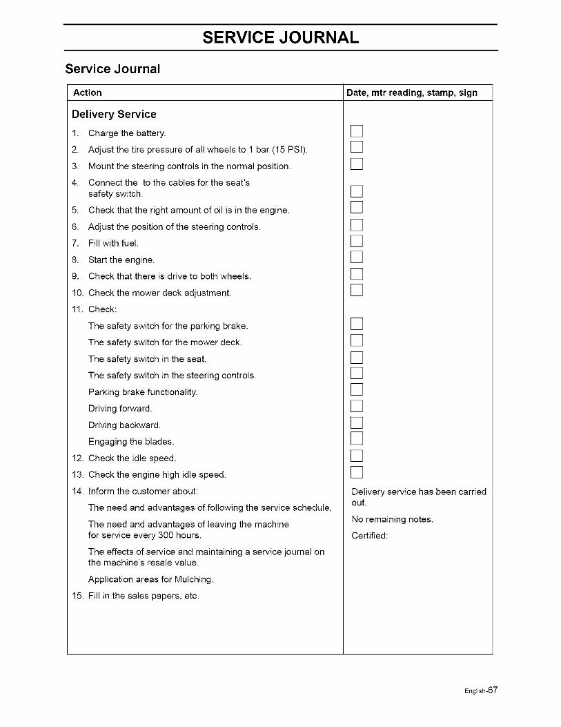
SERVICE JOURNAL
Service Journal
Date, mtr reading, stamp, signAction
Delivery Service
1. Charge the battery.
2. Adjust the tire pressure of all wheels to 1 bar (15 PSI).
3. Mount the steering controls in the normal position.
4. Connect the to the cables for the seat's
safety switch.
5. Check that the right amount of oil is in the engine.
6. Adjust the position of the steering controls.
7. Fill with fuel.
8. Start the engine.
9. Check that there is drive to both wheels.
10. Check the mower deck adjustment.
11. Check:
The safety switch for the parking brake.
The safety switch for the mower deck.
The safety switch in the seat.
The safety switch in the steering controls.
Parking brake functionality.
Driving forward.
Driving backward.
Engaging the blades.
12. Check the idle speed.
13. Check the engine high idle speed.
14. Inform the customer about:
The need and advantages of following the service schedule.
The need and advantages of leaving the machinefor service every 300 hours.
The effects of service and maintaining a service journal onthe machine's resale value.
Application areas for Mulching.
15. Fill in the sales papers, etc.
[][][]
[][][][][][][]
[][][][][][][][][][]Delivery service has been carriedout.
No remaining notes.
Certified:
English-67

SERVICE JOURNAL
After the First 5-8 Hours
1. Change engine oil. []
English-68
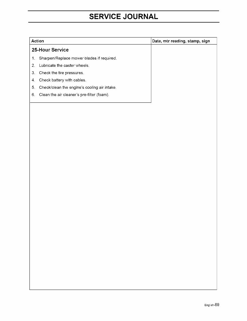
SERVICE JOURNAL
Date, mtr reading, stamp, signAction
25-Hour Service
1.
2.
3.
4.
5.
6.
Sharpen/Replace mower blades if required.
Lubricate the caster wheels.
Check the tire pressures.
Check battery with cables.
Check/clean the engine's cooling air intake.
Clean the air cleaner's pre-filter (foam).
English-69
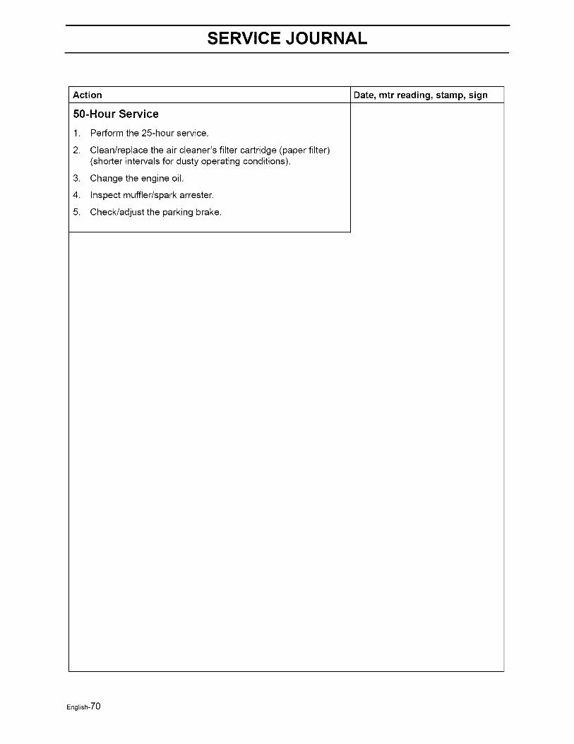
SERVICE JOURNAL
Date, mtr reading, stamp, signAction
50-Hour Service
1.
2.
.
4.
5.
Perform the 25-hour service.
Clean/replace the air cleaner's filter cartridge (paper filter)(shorter intervals for dusty operating conditions).
Change the engine oil.
Inspect muffler/spark arrester.
Check/adjust the parking brake.
English-70
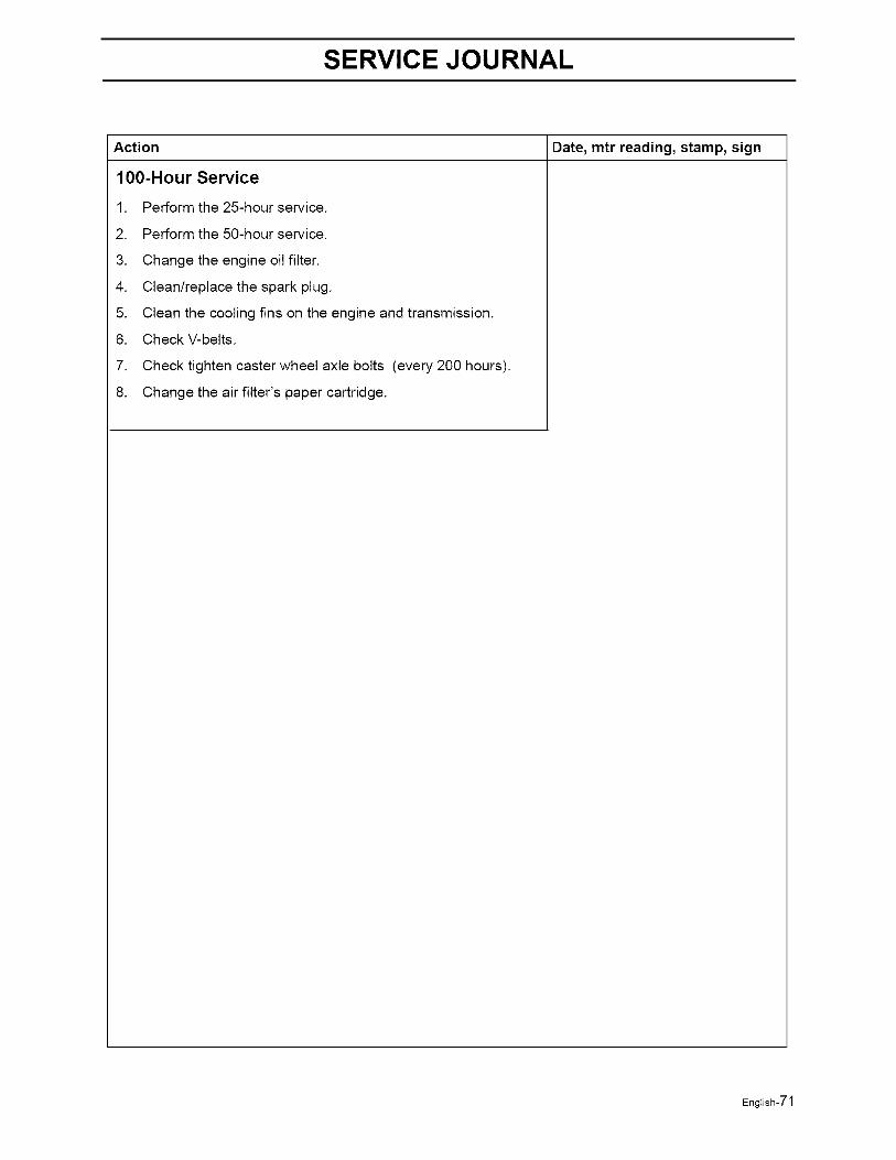
SERVICE JOURNAL
Date, mtr reading, stamp, signAction
100-Hour Service
1.
2.
3.
4.
5.
6.
7.
8.
Perform the 25-hour service.
Perform the 50-hour service.
Change the engine oil filter.
Clean/replace the spark plug.
Clean the cooling fins on the engine and transmission.
Check V-belts.
Check tighten caster wheel axle bolts (every 200 hours).
Change the air filter's paper cartridge.
English-71
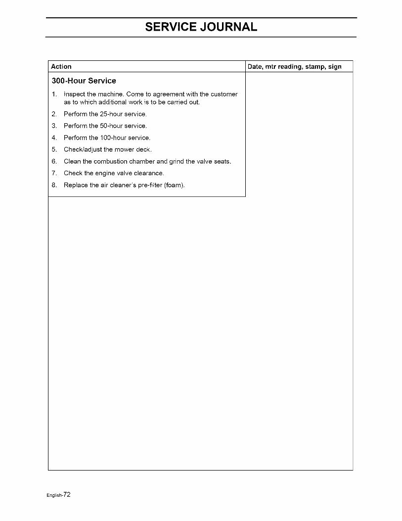
SERVICE JOURNAL
Date, mtr reading, stamp, signAction
300-Hour Service
1. Inspect the machine. Come to agreement with the customeras to which additional work is to be carried out.
2. Perform the 25-hour service.
3. Perform the 50-hour service.
4. Perform the 100-hour service.
5. Check/adjust the mower deck.
6. Clean the combustion chamber and grind the valve seats.
7. Check the engine valve clearance.
8. Replace the air cleaner's pre-fllter (foam).
English-72
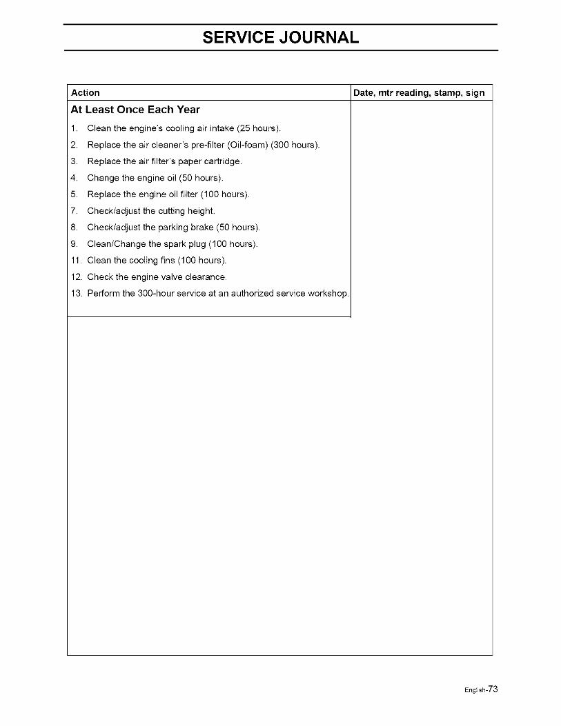
SERVICE JOURNAL
Date, mtr reading, stamp, signAction
At Least Once Each Year
1. Clean the engine's cooling air intake (25 hours).
2. Replace the air cleaner's pre-filter (Oil-foam) (300 hours).
3. Replace the air filter's paper cartridge.
4. Change the engine oil (50 hours).
5. Replace the engine oil filter (100 hours).
7. Check/adjust the cutting height.
8. Check/adjust the parking brake (50 hours).
9. Clean/Change the spark plug (100 hours).
11. Clean the cooling fins (100 hours).
12. Check the engine valve clearance.
13. Perform the 300-hour service at an authorized service workshop.
English-73

113926Rir 06/05/06