operator’s manual scd501bn08-vxx - american · pdf fileoperator’s manual...
TRANSCRIPT

OPERATOR’S MANUAL SCD501BN08-VXXINCLUDING: OPERATION, INSTALLATION & MAINTENANCE RELEASED: 5-25-15
REVISED 11-20-15(REV: B)AUTOMATIC DEWATERING SYSTEM
INGERSOLL RAND COMPANY LTD209 NORTH MAIN STREET – BRYAN, OHIO 43506 (800) 495-0276 FAX (800) 892-6276 © 2015 CCN 47533490001arozone.com
READ THIS MANUAL CAREFULLY BEFORE INSTALLING,OPERATING OR SERVICING THIS EQUIPMENT.
It is the responsibility of the employer to place this information in the hands of the operator. Keep for future reference.
MODEL DESCRIPTION CHART
SC D 5 01 B N 08 - VX X
ARO StandardSolution
ApplicationD - Dewatering
PLC Control OptionB - No PLC
Fluid5 - Water
Type01 - Pneumatic liquid level control
Metering OptionN - No metering
Industry08 - Mining
Liquid LevelSensor VersionV1 - StandardV2 - Low level anti-block
Installation StyleD – w/bracket for 2”and 3” PRO and EXP pumps
GENERAL DESCRIPTIONThe ARO® Automatic Dewatering System (ADS) offersautomatic on/off controls of air operated diaphragm pumps.The ADS has a Liquid Level Sensor (LLS) which produces a pneumatic output signal as the fluid level in an unpressurized vessel rises past a predetermined level and stops the signal as the fluid level falls past a lower predetermined level. This pneumatic signal actuates the Pneumatic Controlled Valve (PCV) in order to open the air line and start the diaphragm pump. The liquid level range can be set by changing the loca-tion of the tail ends of the “High Level” and “Low Level” sensing tubes.
SERVICE KITSUse only genuine ARO® replacement parts to assure compat-ible pressure rating and longest service life.
SS-BQG550 for universal bracket replacement.PNCV-1/2 for pneumatic controlled valve replacement.637523 for Tubing kit replacement.
Figure 1
COMPONENTS INCLUDED WITH KIT
LLS-SC-VX Liquid Level Sensor (LLS), Version 1 or 2SS-BQG550 Universal Mounting Bracket637523 Tubing Kit (includes 20m of 6mm tubing and two filters)PNCV-1/2 Pneumatic Controlled Valve (PCV) Module Assembly97999-7154 Operator’s Manual
Page 2 of 8 SCD501BN08-VXX (en)
INSTALLATION
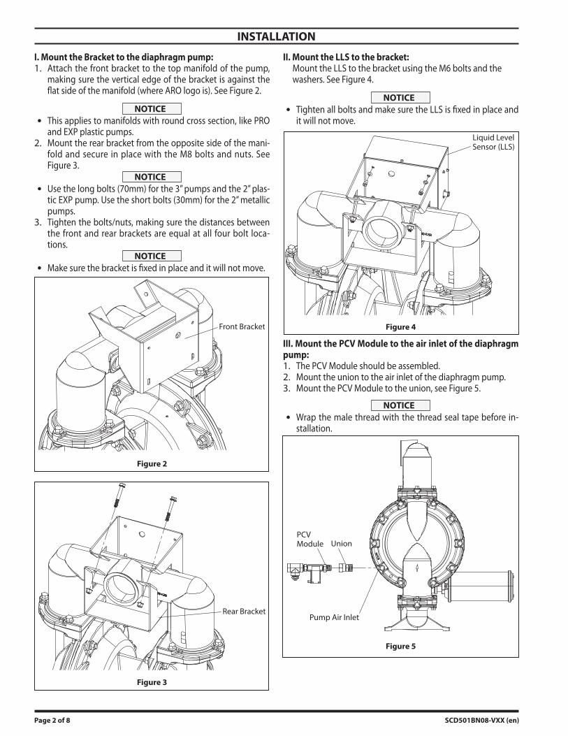
I. Mount the Bracket to the diaphragm pump:Attach the front bracket to the top manifold of the pump, making sure the vertical edge of the bracket is against the flat side of the manifold (where ARO logo is). See Figure 2.
NOTICEThis applies to manifolds with round cross section, like PRO and EXP plastic pumps.Mount the rear bracket from the opposite side of the mani-fold and secure in place with the M8 bolts and nuts. See Figure 3.
NOTICEUse the long bolts (70mm) for the 3” pumps and the 2” plas-tic EXP pump. Use the short bolts (30mm) for the 2” metallic pumps.Tighten the bolts/nuts, making sure the distances between the front and rear brackets are equal at all four bolt loca-tions.
NOTICEMake sure the bracket is fixed in place and it will not move.
Front Bracket
Figure 2
Rear Bracket
Figure 3
1.
2.
3.
II. Mount the LLS to the bracket: Mount the LLS to the bracket using the M6 bolts and the washers. See Figure 4.
NOTICETighten all bolts and make sure the LLS is fixed in place and it will not move.
Liquid Level Sensor (LLS)
Figure 4
III. Mount the PCV Module to the air inlet of the diaphragm pump:
The PCV Module should be assembled.Mount the union to the air inlet of the diaphragm pump.Mount the PCV Module to the union, see Figure 5.
NOTICEWrap the male thread with the thread seal tape before in-stallation.
PCV Module Union
Pump Air Inlet
Figure 5
1.2.3.
SCD501BN08-VXX (en) Page 3 of 8
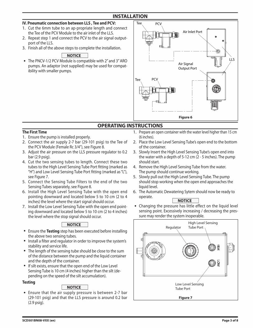
INSTALLATIONIV. Pneumatic connection between LLS , Tee and PCV:
Cut the 6mm tube to an ap-propriate length and connect the Tee of the PCV Module to the air inlet of the LLS.Repeat step 1 and connect the PCV to the air signal output-port of the LLS.Finish all of the above steps to complete the installation.
NOTICEThe PNCV-1/2 PCV Module is compatible with 2” and 3” ARO pumps. An adaptor (not supplied) may be used for compat-ibility with smaller pumps.
1.
2.
3.
Tee
Tee
Air Inlet Port
LLSAir SignalOutput Port
PCV
PCV
Figure 6
OPERATING INSTRUCTIONSThe First Time
Ensure the pump is installed properly.Connect the air supply 2-7 bar (29-101 psig) to the Tee of the PCV Module (Female Rc 3/4”), see Figure 8.Adjust the air pressure on the LLS pressure regulator to 0.2 bar (2.9 psig).Cut the two sensing tubes to length. Connect these two tubes to the High Level Sensing Tube Port fitting (marked as “H”) and Low Level Sensing Tube Port fitting (marked as “L”), see Figure 7.Connect the Sensing Tube Filters to the end of the two Sensing Tubes separately, see Figure 8.Install the High Level Sensing Tube with the open end pointing downward and located below 5 to 10 cm (2 to 4 inches) the level where the start signal should occur.Install the Low Level Sensing Tube with the open end point-ing downward and located below 5 to 10 cm (2 to 4 inches) the level where the stop signal should occur.
NOTICE
Ensure the Testing step has been executed before installing the above two sensing tubes.Install a filter and regulator in order to improve the system’s stability and service life.The length of the sensing tube should be close to the sum of the distance between the pump and the liquid container and the depth of the container.If silt exists, ensure that the open end of the Low Level Sensing Tube is 10 cm (4 inches) higher than the silt (de-pending on the speed of the silt accumulation).
TestingNOTICE
Ensure that the air supply pressure is between 2-7 bar (29-101 psig) and that the LLS pressure is around 0.2 bar (2.9 psig).
1.2.
3.
4.
5.
6.
7.
Prepare an open container with the water level higher than 15 cm (6 inches).Place the Low Level Sensing Tube’s open end to the bottom of the container.Slowly Insert the High Level Sensing Tube’s open end into the water with a depth of 5-12 cm (2 - 5 inches). The pump should start.Remove the High Level Sensing Tube from the water. The pump should continue working.Slowly pull out the High Level Sensing Tube. The pump should stop working when the open end approaches the liquid level.The Automatic Dewatering Sytem should now be ready to operate.
NOTICEChanging the pressure has little effect on the liquid level sensing point. Excessively increasing / decreasing the pres-sure may render the system inoperable.
RegulatorHigh Level SensingTube Port
Low Level SensingTube Port
Figure 7
1.
2.
3.
4.
5.
6.

Page 4 of 8 SCD501BN08-VXX (en)
SSFT-SC Sensing Tube Filter Installation
Sensing Tube
Tube Filter(Included in 637523 Tubing kit)
SensingTube (20 meters, 65 feet)(Included in 637523 Tubing kit)
SS-BQG550 Bracket
LLS-SC-VXLiquid Level Sensor
PNCV-1/2 Pneumatic Controlled Valve
Figure 8
PARTS LIST / SCD501BN08-VXX
SS-BQG550 MOUNTING BRACKET COMPATIBILITY
The mounting bracket (SS-BQG550) is compatible with the following ARO pumps:
Pump Type Generic Model Number Notes2” metallic EXP PX20X-XXX-XXX-X2” metallic PRO 6662XX-XXX-C2” plastic EXP PX20P-FXS-XXX
3” metallic EXP PX30X-AXX-XXX-X, PX30X-BXX-XXX-X PX30X-FXX-XXX-X is not compatible (flange connection)3” metallic PRO 6663XX-XXX-C

SCD501BN08-VXX (en) Page 5 of 8
DIMENSIONAL DATA
Pump does not work when the liquid level rises above 10 cm (4 inches) higher than the open end of the High Level Sensing Tube.
Check the air supply pressure, normal range is 2-7 bar (29-101 psig). Check the LLS air pressure, normal range is 0.2-0.5 bar (2.9 - 7.25 psig).Check the connections of the Sensing Tubes and the connections of tubes inside the LLS. Ensure that there is no air leakage at the fittings.
Pump stops working when the liquid level falls to the open end of the Low Level Sensing Tube.
The open end of the Low Level Sensing Tube may be blocked by silt. Clean the silt or reinstall the open end to a higher place.
Pump stops working when liquid level approaches the High Level Sensing Tube’s open end. The Low Level Sensing Tube is not functional.
Air supply pressure may drop below 2 bar (29 psig) when the pump starts. Change to a bigger air supply hose or increase the air supply pressure.
D
E
A
C
B
222 mm(8.8 inches)
236.5 mm(9.3 inches)
Figure 9
DIMENSIONS
PumpA B C D E
mm in. mm in. mm in. mm in. mm in.2” metallic EXP 553.1 21.8 711.7 28.0 172.5 6.8 300.0 11.8 723.1 28.52” metallic PRO 466.8 18.4 710.8 28.0 169.5 6.7 297.0 11.7 660.0 26.02” plastic EXP 426.1* 16.8* 819.0 32.2 188.3 7.4 315.9 12.4 731.0 28.8
3” metallic EXP 570.5 22.5 855.4 33.7 195.9 7.7 323.5 12.7 728.1 28.73” metallic PRO 480.0 18.9 856.9 33.7 195.7 7.7 323.3 12.7 664.8 26.2
* NOTE: Dimensions for LLS installed on the same side of the air input line.
TROUBLESHOOTING
Page 6 of 8 SCD501BN08-VXX (en)
NOTES

SCD501BN08-VXX (en) Page 7 of 8
NOTES

Page 8 of 8 SCD501BN08-VXX (en)
PN 97999-1754