operators manual - rotax-owner.com
TRANSCRIPT

FOR ROTAX ENGINE TYPE 912 SERIES REF NO.: OM-912 | PART NO.: 899700
OPERATORSMANUAL
Before starting the engine, read the Operators Manual, as it contains important safety relevant information. Failure to do so may result in per-sonal injuries including death. Consult the original equipment manufactur-ers handbook for additional instructions!
WARNING
These technical data and the information embodied therein are the property of BRP-Rotax GmbH & CO KG, Austria, acc, BGBI 1984 no. 448, and shall not, without prior written permission of BRP-Rotax GmbH & Co KG, be disclosed in whole or in part to third parties. This legend shall be included on any reproduction of these data, in whole or in part. The Manual must remain with the engine/aircraft in case of sale.
Copyright 2020 © - all rights reserved.
ROTAX® is a trade mark of BRP-Rotax GmbH & Co KG. In the following document the short form of BRP-Rotax GmbH & Co KG = BRP-Rotax is used. Other product names in this documentation are used purely for ease of identification and may be trademarks of the respective company or owner.
Translation into other languages might be performed in the course of language localization but does not lie within ROTAX® scope of responsibility.
In any case the original text in English language and the metric units are authoritative.

Effectivity: 912 SerieEdition 4 / Rev. 0
BRP-Rotax Page Content-1November 01/2016
Table of Content
Chapter INTRO – Introduction
Chapter LEP – LIST OF EFFECTIVE PAGES
Chapter TOA – Table of amendments
Chapter 1 – General note
Chapter 2 – Operating instructions
Chapter 3 – Standard operation
Chapter 4 – Abnormal operation
Chapter 5 – Performance and Fuel consumption
Chapter 6 – Weights
Chapter 7 – System Description
Chapter 8 – Preservation and storage
Chapter 9 – Supplement

Page Notes-2November 01/2016
BRP-Rotax Effectivity: 912 SerieEdition 4 / Rev. 0
NOTES
INTRO) Introduction
Topics in this chapter
The structure of the Manual follows whenever it is possible thestructure of the „GAMA Specification #1 for Pilot’s OperatingHandbook“.
Foreword BRP-Rotax GmbH & Co KG (hereinafter “BRP-Rotax”) provides“Instructions of Continued Airworthiness”, which are based onthe design, the tests and certification of the engine and itscomponents.These instructions apply only to engines and componentssupplied by BRP-Rotax. This Operator Manual containsimportant information about safe operation of the engine,together with descriptions of the systems and its layout,technical data, operating media and the operational limits of theengine.The specified data apply only to the engine and not to specificapplications in particular aircraft. The aircraft manufacturersOperators Manual is therefore definitive in terms of theoperation of the engine, as it contains all of the aircraft-specificinstructions.
Effectivity: 912 SerieEdition 4 / Rev. 0
BRP-Rotax Page INTRO-1November 01/2016

Page Notes-2November 01/2016
BRP-Rotax Effectivity: 912 SerieEdition 4 / Rev. 0
NOTES

LEP) LIST OF EFFECTIVE PAGES
Chapter Page Date
coverpage
INTRO 1 Nov. 01 2016
2 Nov. 01 2016
LEP 1 Nov. 01 2016
2 Nov. 01 2016
TOA 1 Nov. 01 2016
2 Nov. 01 2016
1 1 Nov. 01 2016
2 Nov. 01 2016
3 Nov. 01 2016
4 Nov. 01 2016
5 Nov. 01 2016
6 Nov. 01 2016
7 Nov. 01 2016
8 Nov. 01 2016
9 Nov. 01 2016
10 Nov. 01 2016
11 Nov. 01 2016
12 Nov. 01 2016
13 Nov. 01 2016
14 Nov. 01 2016
15 Nov. 01 2016
16 Nov. 01 2016
17 Nov. 01 2016
18 Nov. 01 2016
19 Nov. 01 2016
20 Nov. 01 2016
2 1 Nov. 01 2016
2 Nov. 01 2016
Chapter Page Date
3 Nov. 01 2016
4 Nov. 01 2016
5 Nov. 01 2016
6 Nov. 01 2016
7 Nov. 01 2016
8 Nov. 01 2016
9 Nov. 01 2016
10 Nov. 01 2016
11 Nov. 01 2016
12 Nov. 01 2016
3 1 Nov. 01 2016
2 Nov. 01 2016
3 Nov. 01 2016
4 Nov. 01 2016
5 Nov. 01 2016
6 Nov. 01 2016
7 Nov. 01 2016
8 Nov. 01 2016
9 Nov. 01 2016
10 Nov. 01 2016
11 Nov. 01 2016
12 Nov. 01 2016
4 1 Nov. 01 2016
2 Nov. 01 2016
3 Nov. 01 2016
4 Nov. 01 2016
5 Nov. 01 2016
6 Nov. 01 2016
7 Nov. 01 2016
8 Nov. 01 2016
Effectivity: 912 SerieEdition 4 / Rev. 0
BRP-Rotax Page LEP-1November 01/2016
Chapter Page Date
5 1 Nov. 01 2016
2 Nov. 01 2016
3 Nov. 01 2016
4 Nov. 01 2016
5 Nov. 01 2016
6 Nov. 01 2016
7 Nov. 01 2016
8 Nov. 01 2016
6 1 Nov. 01 2016
2 Nov. 01 2016
7 1 Nov. 01 2016
2 Nov. 01 2016
3 Nov. 01 2016
Chapter Page Date
4 Nov. 01 2016
5 Nov. 01 2016
6 Nov. 01 2016
7 Nov. 01 2016
8 Nov. 01 2016
8 1 Nov. 01 2016
2 Nov. 01 2016
3 Nov. 01 2016
4 Nov. 01 2016
9 1 Nov. 01 2016
2 Nov. 01 2016
rearpage
Page LEP-2November 01/2016
BRP-Rotax Effectivity: 912 SerieEdition 4 / Rev. 0

TOA) Table of amendments
Approval*The technical content of this document is approved under the authority of
DOA ref. EASA.21J.048.
cur-rentno.
chap-ter
page date ofchange
remarkfor
appro-val
date ofapprovalfrom
authori-ties
date ofinclusion
sig-na-ture
0 INTRO all Nov. 01 2016 DOA*
0 LEP all Nov. 01 2016 DOA*
0 TOA all Nov. 01 2016 DOA*
0 1 up to 9 all Nov. 01 2016 DOA*
Effectivity: 912 SerieEdition 4 / Rev. 0
BRP-Rotax Page TOA-1November 01/2016

Summary of amendments
Summary of the relevant amendments in this context, but without any claim tocompleteness.
current no. chapter page date ofchange
comments
0 1 up to 9 all Nov. 01 2016 new layout and change ofcompany name
Page TOA-2November 01/2016
BRP-Rotax Effectivity: 912 SerieEdition 4 / Rev. 0

1) General note
Topics in this chapter
1.1 General ................................................................................................21.2 Abbreviations and terms ........................................................................31.3 Safety ..................................................................................................71.4 Safety information .................................................................................91.5 Technical documentation...................................................................... 121.6 Standard version ................................................................................. 141.6.1 Auxiliary equipment (optional)................................................................ 141.7 Type description.................................................................................. 161.8 Engine components, engine views, cylinder
designation ........................................................................................ 171.9 Technical data ..................................................................................... 181.10 Fuel consumption .............................................................................. 181.11 Direction of rotation ........................................................................... 19
Foreword Before operating the engine, carefully read this OperatorsManual. The Manual provides you with basic information on thesafe operation of the engine.If any passages of the Manual are not clearly understood or incase of any questions, please contact an ROTAX® authorizedaircraft engines distributors or their independent service center.BRP-Rotax wishes you much pleasure and satisfaction flyingyour aircraft powered by this ROTAX®-aircraft engine.
Effectivity: 912 SerieEdition 4 / Rev. 0
BRP-Rotax Page 1-1November 01/2016

1.1) GeneralPurpose The purpose of this Operators Manual is to familiarize the own-
er/user of this aircraft engine with basic operating instructionsand safety information.
Documentation For more detailed information related to aircraft and aircraft/en-gine installation, maintenance, safety- or flight operation, con-sult the documentation provided by the aircraft manufacturerand/or its dealer.For additional information on engines, maintenance or parts,you can also contact your nearest ROTAX® authorized aircraftengines distributor or their independent service center.
Engine serialnumber
When making inquiries or ordering parts, always indicate theengine serial number, as the manufacturer might make modifi-cations to the engine in the course of product improvement.The engine serial number is located on the top of the crank-case, magneto side.
Cyl.1 Cyl.3
Cyl.2 Cyl.4
PTO MAG
Figure .1: Pos. 1: Engine serial number
Page 1-2November 01/2016
BRP-Rotax Effectivity: 912 SerieEdition 4 / Rev. 0

Effectivity: 912 SerieEdition 4 / Rev. 0
BRP-Rotax Page 1-3November 01/2016
1.2) Abbreviations and terms
Abbrevia-tions
Description
* Reference to another section
� center of gravity
The drop symbol indicates use of sealing agents, ad-hesives or lubricants (only in the Illustrated PartsCatalog).
°C Degrees Celsius (Centigrade)
°F Degrees Fahrenheit
rpm Revolutions per minute
A Ampere
AAPTS Ambient Air Pressure Temperature Sensor
AC alternating current
Ah Ampere hour
A/C Aircraft
AR as required (IPC only)
assy. assembly
ASB Alert Service Bulletin
ACG Austro Control GmbH
ACL Anti Collision Light
API American Petrol Institute
ASTM American Society for Testing and Materials
ATA Air Transport Association
AWG American Wire Gauge
CAN Control Area Network
Coil 1–4 Ignition coils 1–4
CPS 1+2 Crankshaft Position Sensor 1+2
CSA Constant Speed Actuator
CTS Cooling Temperature Sensor
CW clockwise
CCW counter-clockwise

CGSB Canadian General Standards Board
DCDI Dual Capacitor Discharge Ignition
DC direct current
DOA Design Organisation Approval
DOT Department of Transport
EASA European Aviation Safety Agency
IM Installation Manual
ECU Engine Control Unit
EGT Exhaust Gas Temperature
INTRO Introduction
EMS Engine Management System
EN European Norm
ETFE Ethylene Tetrafluoroethylene
FAA Federal Aviation Administration
FAR Federal Aviation Regulations
hr. hours
HIC A Harness Interface Connector A
HIC B Harness Interface Connector B
IFR Instrument Flight Rules
INJ 1–8 Injector 1–8
IPC Illustrated Parts Catalog
ips inch per second
iRMT independent ROTAX Maintenance Technician
TOC Table of content
ISA International Standard Atmosphere
kg Kilograms
KNOCK Knock sensor
MAPS 1+2 Manifold Air Pressure Sensor 1+2
MATS 1+2 Manifold Air Temperature Sensor 1+2
MS Magneto Side
MON Motor Octane Number
Page 1-4November 01/2016
BRP-Rotax Effectivity: 912 SerieEdition 4 / Rev. 0
Effectivity: 912 SerieEdition 4 / Rev. 0
BRP-Rotax Page 1-5November 01/2016
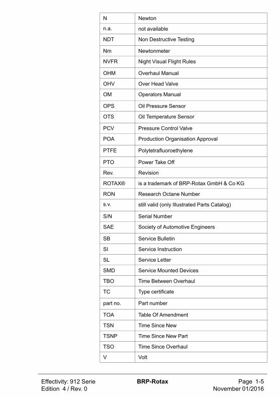
N Newton
n.a. not available
NDT Non Destructive Testing
Nm Newtonmeter
NVFR Night Visual Flight Rules
OHM Overhaul Manual
OHV Over Head Valve
OM Operators Manual
OPS Oil Pressure Sensor
OTS Oil Temperature Sensor
PCV Pressure Control Valve
POA Production Organisation Approval
PTFE Polytetrafluoroethylene
PTO Power Take Off
Rev. Revision
ROTAX® is a trademark of BRP-Rotax GmbH & Co KG
RON Research Octane Number
s.v. still valid (only Illustrated Parts Catalog)
S/N Serial Number
SAE Society of Automotive Engineers
SB Service Bulletin
SI Service Instruction
SL Service Letter
SMD Service Mounted Devices
TBO Time Between Overhaul
TC Type certificate
part no. Part number
TOA Table Of Amendment
TSN Time Since New
TSNP Time Since New Part
TSO Time Since Overhaul
V Volt

VFR Visual Flight Rules
LEP List of Effective Pages
MM Maintenance Manual
XXX shows the serial component number
Page 1-6November 01/2016
BRP-Rotax Effectivity: 912 SerieEdition 4 / Rev. 0

Effectivity: 912 SerieEdition 4 / Rev. 0
BRP-Rotax Page 1-7November 01/2016
1.3) SafetyAlthough reading such information does not eliminate any haz-ards, it promotes the understanding and application the infor-mation will promote correct use of the engine. Always applycommon workshop safety rules.
The information and descriptions of components and systemscontained in this Manual are correct at the time of publication.BRP-Rotax maintains a policy of continuous improvement of itsproducts without imposing upon itself any obligation to retrofitproducts previously manufactured.
Revisions BRP-Rotax reserves the right to remove, replace or discontinueany design, specification, feature or other at any time, and with-out incurring obligation.
Measurement Specifications are given in the SI metric system with the imperi-al- and US customary measurement system equivalents inparenthesis.
Symbols used This Manual uses the following symbols to emphasize particularinformation. This information is important and must beobserved.
mWARNING
Identifies an instruction which, if not followed, may cause seri-ous injury or even fatal injury.
m CAUTION
Identifies an instruction which, if not followed, may cause mi-nor or moderate injury.
ATTENTION
Identifies an instruction which, if not followed, may severelydamage the engine or could lead to suspension of warranty.
NOTE
Indicates supplementary information which may be needed tofully complete or understand an instruction.
ENVIRONMENT NOTE
Environmental notes give you tips on environmentalprotection.
A revision bar outside the page margin indicates a change totext or graphic.
Page 1-8November 01/2016
BRP-Rotax Effectivity: 912 SerieEdition 4 / Rev. 0
Effectivity: 912 SerieEdition 4 / Rev. 0
BRP-Rotax Page 1-9November 01/2016
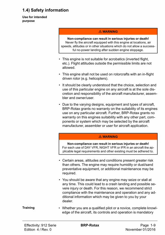
1.4) Safety informationUse for intendedpurpose
mWARNING
Non-compliance can result in serious injuries or death!Never fly the aircraft equipped with this engine at locations, air
speeds, altitudes or in other situations which do not allow a success-ful no-power landing after sudden engine stoppage.
• This engine is not suitable for acrobatics (inverted flight,etc.). Flight attitudes outside the permissible limits are notallowed.
• This engine shall not be used on rotorcrafts with an in-flightdriven rotor (e.g. helicopters).
• It should be clearly understood that the choice, selection anduse of this particular engine on any aircraft is at the sole dis-cretion and responsibility of the aircraft manufacturer, assem-bler and owner/user.
• Due to the varying designs, equipment and types of aircraft,BRP-Rotax grants no warranty on the suitability of its enginesuse on any particular aircraft. Further, BRP-Rotax grants nowarranty on this engines suitability with any other part, com-ponents or system which may be selected by the aircraftmanufacturer, assembler or user for aircraft application.
mWARNING
Non-compliance can result in serious injuries or death!For each use of DAY VFR, NIGHT VFR or IFR in an aircraft the ap-plicable legal requirements and other existing must be adhered to.
• Certain areas, altitudes and conditions present greater riskthan others. The engine may require humidity or dust/sandpreventative equipment, or additional maintenance may berequired.
• You should be aware that any engine may seize or stall atany time. This could lead to a crash landing and possible se-vere injury or death. For this reason, we recommend strictcompliance with the maintenance and operation and any ad-ditional information which may be given to you by yourdealer.
Training • Whether you are a qualified pilot or a novice, complete knowl-edge of the aircraft, its controls and operation is mandatory

before a solo flight. Flying any type of aircraft involves a cer-tain amount of risk. Be informed and prepared for any situa-tion or hazard associated with flying.
• A recognized training program and continued education forpiloting an aircraft is absolutely necessary for all aircraft pi-lots. Make sure you also obtain as much information as possi-ble about your aircraft, its maintenance and operation fromyour dealer.
• Engine-specific training courses are provided by the author-ized distributors according to manufacturer specifications(iRMT).
Regulations • Respect all legal requirements or local rules pertaining toflight operation in your flying area. Only fly when and whereconditions, topography, and airspeeds are safest.
• Consult your aircraft dealer or manufacturer and obtain thenecessary information, especially before flying in new areas.
Instrumentation • Select and use proper aircraft instrumentation. This instru-mentation is not included in the ROTAX® engine package.Verification to the latest regulations such as FAR or EASAhas to be conducted by the aircraft manufacturer.
Engine log book • Keep an engine log book and respect engine and aircraftmaintenance schedules. Keep the engine in top operatingcondition at all times. Do not operate any aircraft which is notproperly maintained or has engine operating irregularitieswhich have not been corrected.
Maintenance(iRMT)
• Since special training, tools and equipment are required, en-gine servicing shall only be performed by an authorizedROTAX® aircraft engine distributor or their independent serv-ice center. BRP-Rotax requires that any service or mainte-nance work carried out and verified by a technician that has acurrent iRMT rating.
• When the engine will not be operated for a longer period pro-tect the engine and fuel system from contamination and envi-ronmental exposure.
Engine operation • Never operate the engine without sufficient quantities of oper-ating fluids (oil, coolant, fuel).
• Never exceed the maximum permitted operational limits.
• In the interest of safety, the aircraft must not be left unat-tended while the engine is running.
• To eliminate the risk of injury or damage, ensure any looseequipment or tools are properly secured before starting theengine.
Page 1-10November 01/2016
BRP-Rotax Effectivity: 912 SerieEdition 4 / Rev. 0

Effectivity: 912 SerieEdition 4 / Rev. 0
BRP-Rotax Page 1-11November 01/2016
• Allow the engine to cool at idle for several minutes beforeturning off the engine.
Vacuum pump • This engine may be equipped with a vacuum pump. Thesafety warning accompanying the vacuum pump must be giv-en to the owner/operator of the aircraft into which the vacuumpump is installed.

1.5) Technical documentationThese documents form the instructions ensuring continued air-worthiness of ROTAX® aircraft engines.The information contained herein is based on data and experi-ence that are considered applicable for authorized mechanics(iRMT, see Maintenance Manual Line) under normal conditions.Due to the fast technical progress and fulfillment of particularspecifications of the customers it may occur that existing laws,safety prescriptions, constructional and operational regulationsmay not be sufficient or cannot be transferred completely to theobject bought, in particular for special constructions.
Documentation
• Installation Manual
• Operators Manual
• Maintenance Manual (Line and HeavyMaintenance)
• Overhaul Manual
• Illustrated Parts Catalog
• Alert Service Bulletins
• Service Bulletins
• Service Instructions
• Service Letters
Status The status of Manuals can be determined by checking the tableof amendments. The first column of this table indicates the revi-sion status which should be compared with the revision pro-vided on the ROTAX®-Website: www.FLYROTAX.comAmendments and current versions can be downloaded free ofchange.
Replacementpages
Furthermore the Manual is constructed in such a way that singlepages can be replaced instead of the complete document. Thelist of effective pages is given in the chapter LEP. The particularedition and revision number is given on the footer of each page.
Reference Any reference to a document refers to the latest edition issuedby BRP-Rotax if not stated otherwise.
Illustrations The illustrations in this Manual are merely sketches and showtypical arrangements. They may not represent full detail or theexact shape of the parts but should outline the same or similarfunction. Therefore deriving dimensions or other details from il-lustrations is not permitted.
Page 1-12November 01/2016
BRP-Rotax Effectivity: 912 SerieEdition 4 / Rev. 0
Effectivity: 912 SerieEdition 4 / Rev. 0
BRP-Rotax Page 1-13November 01/2016
TYPICAL indicates a general view which may not represent ex-act details..
NOTE
The Illustrations in this Manual are stored in a graphic database system and are provided with a consecutive irrelevantnumber.This number (e.g. AE 5iS001) is of no significance for thecontent.

1.6) Standard versionBasic • 4 stroke, 4 cyl. horizontally opposed, spark ignition engine,
single central camshaft hydraulic tappets - push rods - OHV
• Liquid cooled cylinder heads
• Ram air cooled cylinders
• Dry sump forced lubrication
• Dual ignition of breakerless, capacitor discharge design
• 2 constant depression carburetors
• Mechanical fuel pump
• Electric starter (12 V 0.7 kW), 912 S/ULS (12 V 0.9 kW)
• Integrated AC generator with external rectifier regulator
• Propeller drive via integrated gearbox with mechanical shockabsorber and overload clutch
NOTE
The overload clutch is installed on all serial production aircraftengines which are certified and non-certified aircraft engines ofthe configuration 3.
Optional • Electric starter (12 V 0.9 kW)
• External alternator (12 V 40 A DC)
• Vacuum pump drive
• Hydraulic constant speed propeller governor drive
1.6.1) Auxiliary equipment (optional)Any equipment not included as part of the standard engine ver-sion and thus not a fix component of the engine is not in the vol-ume of supply.Components especially developed and tested for this engineare readily available at BRP-Rotax.
Auxiliary equip-ment certified
The following auxiliary equipment has been developed andtested for this engine.
• Airbox
• External alternator
• Engine suspension frame
• Vacuum pump (feasible on configuration 2)
• Drive for rev counter/hour-meter
Page 1-14November 01/2016
BRP-Rotax Effectivity: 912 SerieEdition 4 / Rev. 0
Effectivity: 912 SerieEdition 4 / Rev. 0
BRP-Rotax Page 1-15November 01/2016
• Oil radiator with connection
• Coolant radiator
• Coolant overflow bottle
Auxiliary equip-ment not certified
The following auxiliary equipment has not been developed andtested for this engine.
• Exhaust system
• Intake filter
• Mechanical rev counter
• Shock mount

1.7) Type descriptionThe type description consists of the following:
e.g.ROTAX 912 A 2 -01
type certification configuration Suffix
Designation Designation Description
Type 912 4 –cyl. horizontally opposed, normal aspiratedengine
Certifica-tion
A Certified to JAR 22 (TC No. EASA.E.121)
F, S Certified to FAR 33 (TC No. E00051 EN) JAR-E(TC No. EASA.E.121)
UL,ULS
Non-certified aircraft engines
Configura-tion
2 Prop shaft with flange for fixed pitch propeller.
3 Prop shaft with flange for constant speed propellerand drive for hydraulic governor for constant speedpropeller.
Suffix –XX Explanation of the type designation suffix, seeSB-912-068
Options Available options (optional equipment) for the engine type men-tioned above:
externalalterna-tor
vacuumpump
drive for revcounter/
hour meter
gover-nor
for configura-tion 2
yes yes yes no
for configura-tion 3
yes no yes yes
NOTE
Conversion of the configuration 2 to configuration 3 may be ac-complished by ROTAX® authorized aircraft engines distributorsor their Independent service centers.
Page 1-16November 01/2016
BRP-Rotax Effectivity: 912 SerieEdition 4 / Rev. 0

Effectivity: 912 SerieEdition 4 / Rev. 0
BRP-Rotax Page 1-17November 01/2016
1.8) Engine components, engine views, cylinder designationSide view
Figure .2: Side view engine
1 Propeller gear box 2Vacuum pump or hydraulicgovernor for constant speedpropeller
Top view Cyl.1 Cyl.3
Cyl.2 Cyl.4
PTO MAG
Figure .3: Top view engine
3 Engine serial number 4 CD carburetor
5 Electric starter 6Expansion tank with excesspressure valve
7 Exhaust flange 8 External alternator

Front view
Figure .4: Front view engine
1.9) Technical data
Description 912 A/F/UL 912 S/ULS
Bore 79.5 mm (3.13 in) 84 mm (3.31 in)
Stroke 61 mm (2.40 in) 61 mm (2.40 in)
Displacement 1211 cm³ (73.9 in³) 1352 cm³ (82.5 in³)
Compression ratio. 9.0 : 1 10.8 : 1
1.10) Fuel consumption
Fuel consumption 912 A/F/UL 912 S/ULS
At take-offperformance
24.0 l/h (6.3 gal/h) 27.0 l/h (7.1 gal/h)
At max. continuousperformance
22.6 l/h (5.6 gal/h) 25.0 l/h (6.6 gal/h)
At 75 % continuousperformance
16.2 l/h (4.3 gal/h) 18.5 l/h (4.9 gal/h)
Specific consumptionat max. continuousperformance
285 g/kWh (0.47 lb/hph)
285 g/kWh (0.47 lb/hph)
Page 1-18November 01/2016
BRP-Rotax Effectivity: 912 SerieEdition 4 / Rev. 0

Effectivity: 912 SerieEdition 4 / Rev. 0
BRP-Rotax Page 1-19November 01/2016
1.11) Direction of rotationDirection ofrotation
Direction of rotation on propeller shaft: counter clockwise,viewed from the front.
Figure .5: Normal direction of propeller rotation (engine)

Page Notes-20November 01/2016
BRP-Rotax Effectivity: 912 SerieEdition 4 / Rev. 0
NOTES

2) Operating instructions
Topics in this chapter
2.1 Operating limits (912 A/F/UL)...................................................................22.2 Operating limits (912 S/ULS) ...................................................................52.3 Operating media-Coolant........................................................................82.4 Operating media – Fuel...........................................................................92.5 Operating media-Lubricants.................................................................. 10
Introduction The data of the certified engine are based on the typecertificate of type 912 A JAR 22 (TC No. EASA.E.121), 912 F/SFAR 33 (TC No. E00051 EN), JAR-E (TC No. EASA.E. 121).
This chapter of the Operators Manual contains the operatinglimits that must be observed to ensure the ROTAX® aircraftengine and standard systems operate safely.
Effectivity: 912 SerieEdition 4 / Rev. 0
BRP-Rotax Page 2-1November 01/2016
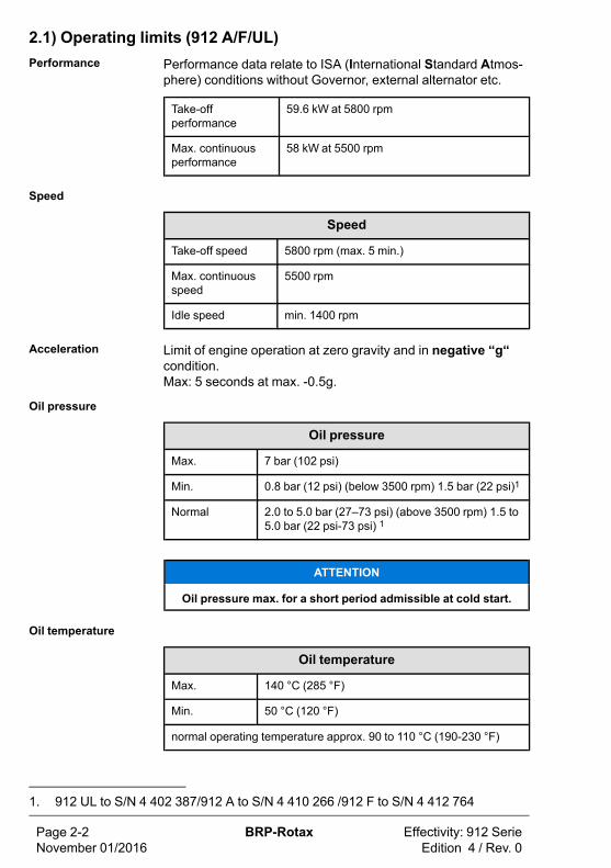
2.1) Operating limits (912 A/F/UL)Performance Performance data relate to ISA (International Standard Atmos-
phere) conditions without Governor, external alternator etc.
Take-offperformance
59.6 kW at 5800 rpm
Max. continuousperformance
58 kW at 5500 rpm
Speed
Speed
Take-off speed 5800 rpm (max. 5 min.)
Max. continuousspeed
5500 rpm
Idle speed min. 1400 rpm
Acceleration Limit of engine operation at zero gravity and in negative “g“condition.Max: 5 seconds at max. -0.5g.
Oil pressure
Oil pressure
Max. 7 bar (102 psi)
Min. 0.8 bar (12 psi) (below 3500 rpm) 1.5 bar (22 psi)1
Normal 2.0 to 5.0 bar (27–73 psi) (above 3500 rpm) 1.5 to5.0 bar (22 psi-73 psi) 1
ATTENTION
Oil pressure max. for a short period admissible at cold start.
Oil temperature
Oil temperature
Max. 140 °C (285 °F)
Min. 50 °C (120 °F)
normal operating temperature approx. 90 to 110 °C (190-230 °F)
Page 2-2November 01/2016
BRP-Rotax Effectivity: 912 SerieEdition 4 / Rev. 0
1. 912 UL to S/N 4 402 387/912 A to S/N 4 410 266 /912 F to S/N 4 412 764

Effectivity: 912 SerieEdition 4 / Rev. 0
BRP-Rotax Page 2-3November 01/2016
EGT
Exhaust gas temperature
Max. 880 °C (1616 °F)
Conventionalcoolant
Applicable for engine S/N without Suffix -01. See also Chapter2.3.
Coolant temperature: (coolant exit temperature)
Max. 120 °C (248 °F)
Cylinder head temperature:
Max. 150 °C (300 °F)
Permanent monitoring of coolant temperature and cylinder headtemperature is necessary.
Waterless coolant See also Chapter 2.3
Cylinder head temperature:
Max. 150 °C (300 °F)
Permanent monitoring of cylinder head temperature is necessary.
Conventionalcoolant
See also Chapter 2.3
Applicable for engine S/N with Suffix -01.
Coolant temperature limit measured inthe cylinder head
Engine type
Max. 120 °C (248 °F) 912 A/F/UL
Permanent monitoring of coolant temperature is necessary.
Engine start, oper-ating temperature
Max. 50 °C (120 °F) (ambient temperature)
Min. -25 °C (-13 °F) (oil temperature)

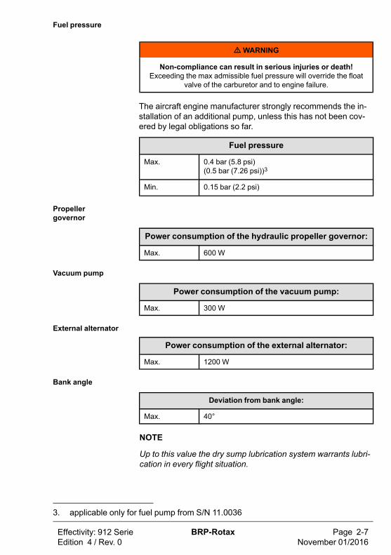
Fuel pressure
mWARNING
Non-compliance can result in serious injuries or death!Fuel pressure in excess of stated limit can lead to an override of the
float valve with subsequent engine stop.
The aircraft engine manufacturer strongly recommends the in-stallation of an additional pump, unless this has not been cov-ered by legal obligations so far.
Fuel pressure
Max. 0.4 bar (5.8 psi)(0.5 bar (7.26 psi))2
Min. 0.15 bar (2.2 psi)
Propellergovernor
Power consumption of the hydraulic propeller governor:
Max. 600 W
Vacuum pump
Power consumption of the vacuum pump:
Max. 300 W
External alternator
Power consumption of the external alternator:
Max. 1200 W
Bank angle
Deviation from bank angle:
Max. 40°
NOTE
Up to this value the dry sump lubrication system warrants lubri-cation in every flight situation.
Page 2-4November 01/2016
BRP-Rotax Effectivity: 912 SerieEdition 4 / Rev. 0
2. applicable only for fuel pump from S/N 11.0036

Effectivity: 912 SerieEdition 4 / Rev. 0
BRP-Rotax Page 2-5November 01/2016
2.2) Operating limits (912 S/ULS)Performance Performance data relate to ISA (International Standard Atmos-
phere) conditions without Governor, external alternator etc.
Take-offperformance
73.5 kW at 5800 rpm
Max. continuousperformance
69 kW at 5500 rpm
Speed
Speed
Take-off speed 5800 rpm (max. 5 min.)
Max. continuousspeed
5500 rpm
Idle speed min. 1400 rpm
Acceleration Limit of engine operation at zero gravity and in negative„g“condition.Max. 5 seconds at max. -0.5 g
Oil pressure
Oil pressure
Max. 7 bar (102 psi)
Min. 0.8 bar (12 psi) (below 3500 rpm)
Normal 2.0 to 5.0 bar (29-73 psi) (above 3500 rpm)
ATTENTION
Oil pressure max. for a short period admissible at cold start.
Oil temperature
Oil temperature
Max. 130 °C (266 °F)
Min. 50 °C (120 °F)
normal operating temperature: approx. 90 to 110 °C (190-230 °F)

EGT
Exhaust gas temperature
Max. 880 °C (1616 °F)
Conventionalcoolant
See also Chapter 2.3.
Applicable for engine S/N without Suffix -01.
Coolant temperature: (coolant exit temperature)
Max. 120 °C (248 °F)
Cylinder head temperature
Max. 135 °C (275 °F)
Permanent monitoring of coolant temperature and cylinder headtemperature is necessary.
Waterless coolant
Cylinder head temperature
Max. 135 °C (275 °F)
Permanent monitoring of cylinder head temperature is necessary.
Conventionalcoolant
Applicable for engine S/N with Suffix -01.
Coolant temperature limitmeasured in cylinder head
Engine type
Max. 120 °C (248 °F) 912 S/ULS
Permanent monitoring of coolant temperature is necessary.
Engine start, oper-ating temperature
Max. 50 °C (120 °F) (ambient temperature)
Min. -25 °C (-13 °F) (Oil temperature)
Page 2-6November 01/2016
BRP-Rotax Effectivity: 912 SerieEdition 4 / Rev. 0
Effectivity: 912 SerieEdition 4 / Rev. 0
BRP-Rotax Page 2-7November 01/2016
Fuel pressure
mWARNING
Non-compliance can result in serious injuries or death!Exceeding the max admissible fuel pressure will override the float
valve of the carburetor and to engine failure.
The aircraft engine manufacturer strongly recommends the in-stallation of an additional pump, unless this has not been cov-ered by legal obligations so far.
Fuel pressure
Max. 0.4 bar (5.8 psi)(0.5 bar (7.26 psi))3
Min. 0.15 bar (2.2 psi)
Propellergovernor
Power consumption of the hydraulic propeller governor:
Max. 600 W
Vacuum pump
Power consumption of the vacuum pump:
Max. 300 W
External alternator
Power consumption of the external alternator:
Max. 1200 W
Bank angle
Deviation from bank angle:
Max. 40°
NOTE
Up to this value the dry sump lubrication system warrants lubri-cation in every flight situation.
3. applicable only for fuel pump from S/N 11.0036

2.3) Operating media-Coolant
ATTENTION
Obey the latest edition of Service Instruction SI-912-016, for theselection of the correct coolant.
Conventionalcoolant
Conventional coolant mixed with water has the advantage of ahigher specific thermal capacity than water-less coolant.
Application When correctly applied, there is sufficient protection against va-por bubble formation, freezing or thickening of the coolant with-in the operating limits.Use the coolant specified in the manufacturers documentation.
Mixture
ATTENTION
Obey the manufacturers instructions!
Applicable for engine S/N without Suffix -01.
Mixture ratio %
Designation Concentrate Water
conventional e.g. BASFGlysantine anticorrosion
50* 50
waterless e.g. Aero Cool180°
100 0
* coolant component can be increased up to max. 65 %.
Applicable for engine S/N with Suffix -01.
Mixture ratio %
Designation Concentrate Water
conventional e.g. BASFGlysantine anticorrosion
50* 50
* coolant component can be increased up to max. 65 %.
Page 2-8November 01/2016
BRP-Rotax Effectivity: 912 SerieEdition 4 / Rev. 0

Effectivity: 912 SerieEdition 4 / Rev. 0
BRP-Rotax Page 2-9November 01/2016
2.4) Operating media – Fuel
ATTENTION
Obey the latest edition of Service Instruction SI-912-016, for theselection of the correct coolant.
ATTENTION
Use only fuel suitable for the respective climatic zone.
NOTE
Risk of vapour formation if using winter fuel for summeroperation.
Antiknockproperties
The fuels with following specifications can be used.
Usage/Description
Anti knock properties912 A/F/UL 912 S/ULS
Min. RON 90 (min.AKI4
Min. RON 95(min. AKI4 91)
NOTE
For fuels according to ASTM D4814 specifications followingAKI (Anti Knock Index) value has to be observed: min. AKI 91.
MOGAS
Usage/Description
MOGAS 912 A/F/UL 912 S/ULS
European standard EN 228 normalEN 228 super
EN 228 super plus
EN 228 super
EN 228 superplus
AVGAS AVGAS 100LL places greater stress on the valve seats due toits high lead content and forms increased deposits in the com-bustion chamber and lead sediments in the oil system.
4. Anti Knock Index (RON+MON)/2
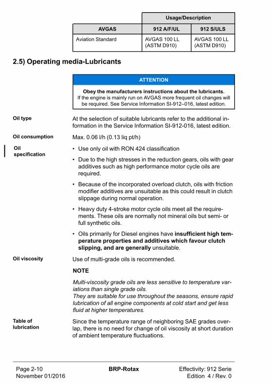
Usage/Description
AVGAS 912 A/F/UL 912 S/ULS
Aviation Standard AVGAS 100 LL(ASTM D910)
AVGAS 100 LL(ASTM D910)
2.5) Operating media-Lubricants
ATTENTION
Obey the manufacturers instructions about the lubricants.If the engine is mainly run on AVGAS more frequent oil changes willbe required. See Service Information SI-912–016, latest edition.
Oil type At the selection of suitable lubricants refer to the additional in-formation in the Service Information SI-912-016, latest edition.
Oil consumption Max. 0.06 l/h (0.13 liq pt/h)
Oilspecification
• Use only oil with RON 424 classification
• Due to the high stresses in the reduction gears, oils with gearadditives such as high performance motor cycle oils arerequired.
• Because of the incorporated overload clutch, oils with frictionmodifier additives are unsuitable as this could result in clutchslippage during normal operation.
• Heavy duty 4-stroke motor cycle oils meet all the require-ments. These oils are normally not mineral oils but semi- orfull synthetic oils.
• Oils primarily for Diesel engines have insufficient high tem-perature properties and additives which favour clutchslipping, and are generally unsuitable.
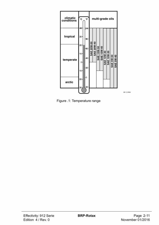
Oil viscosity Use of multi-grade oils is recommended.
NOTE
Multi-viscosity grade oils are less sensitive to temperature var-iations than single grade oils.They are suitable for use throughout the seasons, ensure rapidlubrication of all engine components at cold start and get lessfluid at higher temperatures.
Table oflubrication
Since the temperature range of neighboring SAE grades over-lap, there is no need for change of oil viscosity at short durationof ambient temperature fluctuations.
Page 2-10November 01/2016
BRP-Rotax Effectivity: 912 SerieEdition 4 / Rev. 0
Effectivity: 912 SerieEdition 4 / Rev. 0
BRP-Rotax Page 2-11November 01/2016
Figure .1: Temperature range

Page Notes-12November 01/2016
BRP-Rotax Effectivity: 912 SerieEdition 4 / Rev. 0
NOTES

3) Standard operation
Topics in this chapter
3.1 Daily checks .........................................................................................23.2 Before engine start ................................................................................53.3 Pre-flight checks ...................................................................................53.4 Engine start ..........................................................................................63.5 After engine start ...................................................................................83.6 Take-off ................................................................................................93.7 Cruising ...............................................................................................93.8 Engine shut-off.................................................................................... 103.9 Cold weather operation ........................................................................ 10
Introduction To warrant reliability and efficiency of the engine, meet andcarefully observe all the operating and maintenanceinstructions.The following description of procedures depends on therespective type of installation in the aircraft and shall thereforeonly be seen functionally.
Effectivity: 912 SerieEdition 4 / Rev. 0
BRP-Rotax Page 3-1November 01/2016
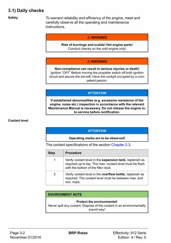
3.1) Daily checksSafety To warrant reliability and efficiency of the engine, meet and
carefully observe all the operating and maintenanceinstructions.
mWARNING
Risk of burnings and scalds! Hot engine parts!Conduct checks on the cold engine only!
mWARNING
Non-compliance can result in serious injuries or death!Ignition “OFF” Before moving the propeller switch off both ignitioncircuit and secure the aircraft. Have the cockpit occupied by a com-
petent person.
ATTENTION
If established abnormalities (e.g. excessive resistance of theengine, noise etc.) inspection in accordance with the relevantMaintenance Manual is necessary. Do not release the engine in-
to service before rectification.
Coolant level
ATTENTION
Operating media are to be observed!
The coolant specifications of the section Chapter 2.3.
Step Procedure
1 Verify coolant level in the expansion tank, replenish asrequired up to top. The max. coolant level must be flushwith the bottom of the filler neck.
2 Verify coolant level in the overflow bottle, replenish asrequired. The coolant level must be between max. andmin. mark.
ENVIRONMENT NOTE
Protect the environmental!Never spill any coolant. Dispose of the coolant in an environmentally
sound way!
Page 3-2November 01/2016
BRP-Rotax Effectivity: 912 SerieEdition 4 / Rev. 0

Effectivity: 912 SerieEdition 4 / Rev. 0
BRP-Rotax Page 3-3November 01/2016
Expansion tank
Figure .1: Expansion tank
1 Radiator cap 2 Expansion tank
Overflow bottle
coolant
Figure .2: Overflow bottle
1 Overflow bottle 2 Coolant
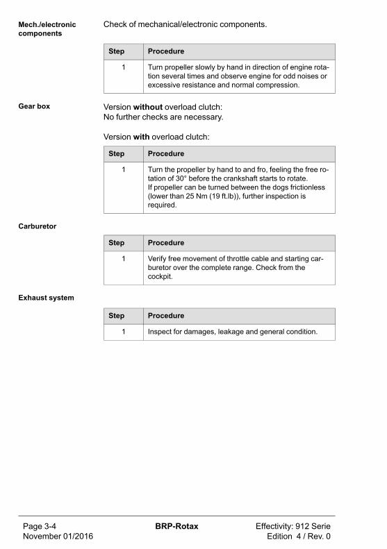
Mech./electroniccomponents
Check of mechanical/electronic components.
Step Procedure
1 Turn propeller slowly by hand in direction of engine rota-tion several times and observe engine for odd noises orexcessive resistance and normal compression.
Gear box Version without overload clutch:No further checks are necessary.
Version with overload clutch:
Step Procedure
1 Turn the propeller by hand to and fro, feeling the free ro-tation of 30° before the crankshaft starts to rotate.If propeller can be turned between the dogs frictionless(lower than 25 Nm (19 ft.lb)), further inspection isrequired.
Carburetor
Step Procedure
1 Verify free movement of throttle cable and starting car-buretor over the complete range. Check from thecockpit.
Exhaust system
Step Procedure
1 Inspect for damages, leakage and general condition.
Page 3-4November 01/2016
BRP-Rotax Effectivity: 912 SerieEdition 4 / Rev. 0
Effectivity: 912 SerieEdition 4 / Rev. 0
BRP-Rotax Page 3-5November 01/2016
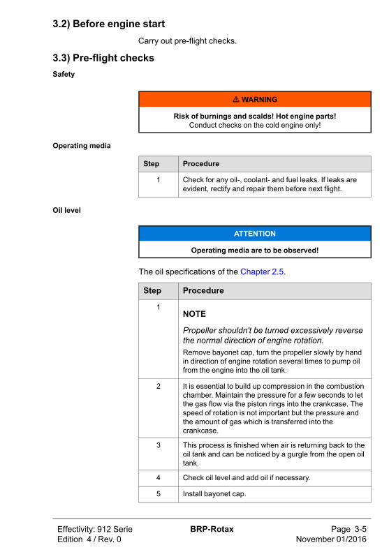
3.2) Before engine startCarry out pre-flight checks.
3.3) Pre-flight checksSafety
mWARNING
Risk of burnings and scalds! Hot engine parts!Conduct checks on the cold engine only!
Operating media
Step Procedure
1 Check for any oil-, coolant- and fuel leaks. If leaks areevident, rectify and repair them before next flight.
Oil level
ATTENTION
Operating media are to be observed!
The oil specifications of the Chapter 2.5.
Step Procedure
1NOTE
Propeller shouldn't be turned excessively reversethe normal direction of engine rotation.Remove bayonet cap, turn the propeller slowly by handin direction of engine rotation several times to pump oilfrom the engine into the oil tank.
2 It is essential to build up compression in the combustionchamber. Maintain the pressure for a few seconds to letthe gas flow via the piston rings into the crankcase. Thespeed of rotation is not important but the pressure andthe amount of gas which is transferred into thecrankcase.
3 This process is finished when air is returning back to theoil tank and can be noticed by a gurgle from the open oiltank.
4 Check oil level and add oil if necessary.
5 Install bayonet cap.
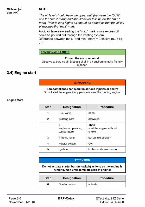
Oil level (oildipstick)
NOTE
The oil level should be in the upper half (between the “50%“and the “max“ mark) and should never falls below the “min.“mark. Prior to long flights oil should be added so that the oil lev-el reaches the “max“ mark.Avoid oil levels exceeding the “max“ mark, since excess oilcould be poured out through the venting system.Difference between max.- and min.- mark = 0.45 litre (0.95 liqpt).
ENVIRONMENT NOTE
Protect the environmental.Observe to bury no oil! Dispose of oil in an environmentally friendly
manner.
3.4) Engine start
mWARNING
Non-compliance can result in serious injuries or death!Do not start the engine if any person is near the running engine.
Engine start
Step Designation Procedure
1 Fuel valve open
2 Starting carb activated
IFengine in operatingtemperature
Thenstart the engine withoutchoke.
3 Throttle lever set on idle position
4 Master switch ON
5 Ignition both circuits switched on
ATTENTION
Do not actuate starter button (switch) as long as the engine isrunning. Wait until complete stop of engine!
Step Designation Procedure
6 Starter button actuate
Page 3-6November 01/2016
BRP-Rotax Effectivity: 912 SerieEdition 4 / Rev. 0

Effectivity: 912 SerieEdition 4 / Rev. 0
BRP-Rotax Page 3-7November 01/2016
ATTENTION
Activate starter for maximum of 10 seconds only (without inter-ruption), followed by a cooling period of 2 minutes.
Step Designation Procedure
7 As soon as engineruns
adjust throttle to achievesmooth running at approx.2500 rpm.
8 Oil pressure check if oil pressure has ris-en within 10 seconds andmonitor oil pressure. In-crease of engine speed isonly permitted at steady oilpressure readings above 2bar (30 psi).
ATTENTION
At an engine start with low oil temperature, continue to observethe oil pressure as it could drop again due to the increased flowresistance in the suction line. The number of revolutions maybe only so far increased that the oil pressure remains steady.
Step Designation Procedure
9 Starting carb (choke) de-activate
To observe Reduction gear with shock absorber
ATTENTION
Since the engine comprises a reduction gear with shock ab-sorber, take special care of the following:
Step Procedure
1 To prevent impact load, start with throttle lever in idle po-sition or at the most up to 10% open.
2 For the same reason, wait for around 3 sec. after throt-tling back to partial load to reach constant speed beforere-acceleration..
3 For checking the two ignition circuits, only one circuitmay be switched off and on at a time.

3.5) After engine start
mWARNING
Non-compliance can result in serious injuries or death!Do not start the engine if any person is near the running engine.
Warming upperiod
Step Procedure
1 Start warming up period at approx. 2000 rpm for approx.2 minutes.
2 Continue at 2500 rpm, duration depending on ambienttemperature, until oil temperature reaches 50 °C (120 °F).
3 Check temperatures and pressure.
Throttle response
ATTENTION
After a full-load ground test allow a short cooling run at idlespeed to prevent vapour formation in the cylinder head.
Step Procedure
1 Short full throttle ground test (consult Aircraft OperatorsManual since engine speed depends on the propellerused).
Ignition check Check the two ignition circuits at 4000 rpm (approx. 1700 rpmpropeller).
Step Procedure
1 Speed drop with only one ignition circuit must not ex-ceed 300 rpm (approx. 130 rpm propeller).
2 115 rpm (approx. 50 rpm propeller) max. difference ofspeed by use of either circuit, A or B.
NOTE
The propeller speed depends on the actual reduction ratio.
Propellergovernor
Check of hydraulic propeller governor:
Check control of the hydraulic propeller governor to specifica-tions of the manufacturer.
Page 3-8November 01/2016
BRP-Rotax Effectivity: 912 SerieEdition 4 / Rev. 0

Effectivity: 912 SerieEdition 4 / Rev. 0
BRP-Rotax Page 3-9November 01/2016
NOTE
Cycling the propeller governor puts a relatively high load on theengine. Unnecessary cycling or additional checks should beavoided.
3.6) Take-off
mWARNING
Non-compliance can result in serious injuries or death!Monitor Operating limits. Limits must not be exceeded.
Climb Climbing with engine running at take-off performance is permis-sible (max. 5 minutes).See Chapter 2.1 Operating limits
3.7) CruisingPerformance
Step Procedure
1 Set performance as per performance specificationsChapter 5 and respect operating limits as per Chapter2.1 Operating limits.
Oil temperature
Step Procedure
1 Avoid operation below normal operation oil temperature(90 to 110 °C / 194 to 230 °F), as possible formation ofcondensation water in the lubrication system badly influ-ences the oil quality.To evaporate possibly accumulated condensation water,at least once a day 100 °C (212 °F) oil temperature mustbe reached.

3.8) Engine shut-offNormally the cooling down of the engine during descending andtaxiing will be sufficient to allow the engine to be shut off assoon as the aircraft is stopped.At increased operating temperatures make an engine coolingrun of at least minimum 2 minutes.
3.9) Cold weather operationGenerally, an engine service should be carried out before thestart of the cold season.
Coolant For selection of coolant and mixing ratio, see Chapter 2.3.
Lubricant For selection of oil, see table of Lubricants Chapter 2.5.
Cold start • With throttle closed and choke activated (open throttle ren-ders starting carb ineffective)
• Be aware, no spark below crankshaft speed of 220 rpm (pro-peller speed of 90 rpm)
• As performance of electric starter is greatly reduced whenhot, limit starting to periods not much longer than 10 sec.With a well charged battery, adding a second battery will notimprove cold starts
Remedy - Cold start
Step Procedure
1 Use of multigrade oil with the low end viscosity code of 5or 10.
2 Check electrode gap of spark plugs and set it to the mini-mum or fit new spark plugs.
3 Preheat engine.
Icing in the air in-take system
Icing due to humidity.
Carburetor icing due to humidity may occur on the venture andon the throttle valve due to fuel evaporation and leads to per-formance loss and change in mixture.
Remedy • Intake air pre-heating is the only effective remedy. See FlightManual supplied by the aircraft manufacturer
Icing Icing due to water in fuel.
Page 3-10November 01/2016
BRP-Rotax Effectivity: 912 SerieEdition 4 / Rev. 0

Effectivity: 912 SerieEdition 4 / Rev. 0
BRP-Rotax Page 3-11November 01/2016
ATTENTION
Fuels containing alcohol always carry a small amount of waterin solution. In case of temperature changes or increase of alco-hol content, water or a mixture of alcohol and water may settle
and could cause troubles.
Water in fuel will accumulate at the lower parts of the fuel sys-tem and leads to freezing of fuel lines, filters or jets.
Remedy • Use non-contaminated fuel (filtered through suede)
• Generously sized water separators
• Fuel lines routing inclined
• Prevent condensation of humidity, i. e avoid temperature dif-ferences between aircraft and fuel

Page Notes-12November 01/2016
BRP-Rotax Effectivity: 912 SerieEdition 4 / Rev. 0
NOTES
4) Abnormal operation
Topics in this chapter
4.1 Re-Start during flight..............................................................................34.2 Exceeding max. admissible engine speed.................................................34.3 Temperature..........................................................................................34.3.1 Exceeding of max. admissible cooling systemtemperature ................................................................................................34.3.2 Exceeding of max. admissible cyl. headtemperature ................................................................................................34.3.3 Exceeding of max. admissible coolanttemperature ................................................................................................44.3.4 Exceeding of max. admissible oil temperature .............................................44.4 Oil pressure/Fuel pressure......................................................................44.4.1 Oil pressure below minimum - on ground ...................................................54.4.2 Oil pressure above permitted range at low ambienttemperatures...............................................................................................54.5 Engine on fire or fire in the engine
compartment ........................................................................................54.6 Trouble shooting ...................................................................................6
Effectivity: 912 SerieEdition 4 / Rev. 0
BRP-Rotax Page 4-1November 01/2016
Introduction
mWARNING
Non-compliance can result in serious injuries or death!At unusual engine behaviour conduct checks as per Maintenance
Manual Line Chapter 05-50-00 before the next flight.
NOTE
Further checks - see Maintenance Manual.
The following description of procedures depends on therespective type of installation in the aircraft and shall thereforeonly be seen functionally.
Page 4-2November 01/2016
BRP-Rotax Effectivity: 912 SerieEdition 4 / Rev. 0
Effectivity: 912 SerieEdition 4 / Rev. 0
BRP-Rotax Page 4-3November 01/2016
4.1) Re-Start during flightEngine stop If the propeller continues to rotate during flight by windmilling,
but the speed is not sufficient to start the engine, the electricstarter can be used without problems. You must not wait untilthe propeller stands still.
4.2) Exceeding max. admissible engine speedExceeding enginespeed
Reduce the engine speed. Any exceeding of the max. admissi-ble engine speed has to be entered by the pilot into logbook,stating duration and extent of over engine speed.
4.3) Temperature
ATTENTION
Reduce engine power setting to the minimum necessary andcarry out precautionary landing.
4.3.1) Exceeding of max. admissible cooling system temperature
ATTENTION
Reduce engine power setting to the minimum necessary andcarry out precautionary landing.
4.3.2) Exceeding of max. admissible cyl. head temperature
ATTENTION
Reduce engine power setting to the minimum necessary andcarry out precautionary landing.
Cylinder headtemperature max.
Applicable for engine S/N without Suffix -01.
• Any exceeding of the max. admissible cylinder head temper-ature has to be entered by the pilot into the logbook, statingduration and extent of over-temperature condition.
• Carry out an unscheduled maintenance check according toMaintenance Manual Line chapter 05-50-00.
4.3.3) Exceeding of max. admissible coolant temperature
ATTENTION
Reduce engine power setting to the minimum necessary andcarry out precautionary landing.
Coolant tempera-ture max.
Applicable for engine S/N with Suffix -01.
• Any exceeding of the max. admissible coolant temperaturehas to be entered by the pilot into the logbook, stating dura-tion and extent of over-temperature condition.
• Carry out an unscheduled maintenance check according toMaintenance Manual Line chapter 05-50-00.
4.3.4) Exceeding of max. admissible oil temperature
ATTENTION
Reduce engine power setting to the minimum necessary andcarry out precautionary landing.
Exceeding oiltemperature
• Any exceeding of the max. oil temperature must be enteredby the pilot in the logbook, stating duration and extent ofover-temperature condition.
• A maintenance inspection should be carried out.
4.4) Oil pressure/Fuel pressure
ATTENTION
Reduce engine power setting to the minimum necessary andcarry out precautionary landing.
Oil pressure Oil pressure below minimum - during flight
• Check oil system.
• A maintenance inspection should be carried out.
Page 4-4November 01/2016
BRP-Rotax Effectivity: 912 SerieEdition 4 / Rev. 0

Effectivity: 912 SerieEdition 4 / Rev. 0
BRP-Rotax Page 4-5November 01/2016
4.4.1) Oil pressure below minimum - on ground
ATTENTION
Reduce engine power setting to the minimum necessary andcarry out precautionary landing.
Oil pressure toolow
Immediately stop the engine and check for reason. Check oilsystem.
• Check oil quantity in oil tank.
• Check oil quality. See Chapter: Operating media-Lubricants.
• A maintenance inspection should be carried out.
4.4.2) Oil pressure above permitted range at low ambienttemperatures
ATTENTION
Reduce engine power setting to the minimum necessary andcarry out precautionary landing.
Oil pressuretoo high
• Reduce engine speed and check the oil pressure again onceit has reached a higher oil temperature.
• A maintenance inspection should be carried out.
4.5) Engine on fire or fire in the engine compartment
ATTENTION
Carry out emergency procedures as prescribed in the flight man-ual of the engine manufacturer.
• After landing locate the cause of fire and resolve the error be-fore next flight by qualified staff (authorized by the AviationAuthorities).
• An entry in the logbook must be made.
• A maintenance inspection should be carried out.

4.6) Trouble shooting
mWARNING
Non-compliance can result in serious injuries or death!Only qualified staff (authorized by the Aviation Authorities) trained
on this particular engine, is allowed to carry out maintenance and re-pair work.
ATTENTION
If the following hints regarding remedy do not solve the prob-lem, contact an authorized workshop. The engine must not be
operated until the problem is rectified.
All checks in accordance with the Maintenance Manual (currentissue/revision).
Starting problems Engine does not start
Possible cause Remedy
Ignition off. Switch on.
Closed fuel valve or cloggedfilter.
Open valve, clean or renew filter,check fuel system for leaks.
No fuel in tank. Refuel.
Starting speed too low,faulty or discharged battery.
Fit fully charged battery.
Starting speed too low, startproblems on cold engine.
Use top quality, low friction oil; allowfor sufficient cooling period to coun-ter for performance drop on hot start-er; preheat engine.
Wrong fuel (Jetfuel orDiesel).
Change of fuel.
Engine run Engine keeps running with ignition off
Possible cause Remedy
Overheating of engine. Let engine cool down at idling at ap-prox. 2000 rpm.
Knocking under load
Possible cause Remedy
Octane rating of fuel toolow.
Use fuel with higher octane rating.
Page 4-6November 01/2016
BRP-Rotax Effectivity: 912 SerieEdition 4 / Rev. 0
Effectivity: 912 SerieEdition 4 / Rev. 0
BRP-Rotax Page 4-7November 01/2016
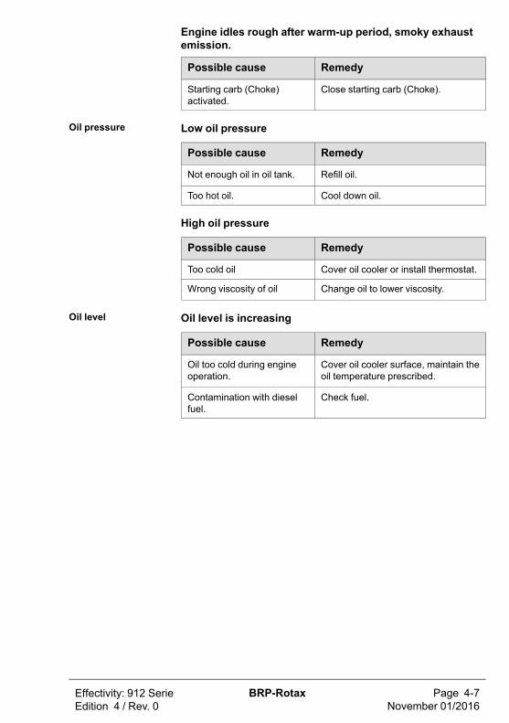
Engine idles rough after warm-up period, smoky exhaustemission.
Possible cause Remedy
Starting carb (Choke)activated.
Close starting carb (Choke).
Oil pressure Low oil pressure
Possible cause Remedy
Not enough oil in oil tank. Refill oil.
Too hot oil. Cool down oil.
High oil pressure
Possible cause Remedy
Too cold oil Cover oil cooler or install thermostat.
Wrong viscosity of oil Change oil to lower viscosity.
Oil level Oil level is increasing
Possible cause Remedy
Oil too cold during engineoperation.
Cover oil cooler surface, maintain theoil temperature prescribed.
Contamination with dieselfuel.
Check fuel.

Cold engine start Engine hard to start at low temperature
Possible cause Remedy
Starting speed too low. Preheat engine.
Low charge battery. Fit fully charged battery.
High oil pressure. At cold start an oil pressure readingof up to around 7 bar (102 psi) doesnot indicate a malfunction.
Oil pressure too low aftercold start.
Too much resistance in the oil suc-tion system at low temperatures dueto cold oil. Stop engine and preheatoil. After a cold start the oil tank mustbe observed and the oil pressureshould be above 1.5 bar (22 psi).Otherwise, the speed must be low-ered again, because not enough coldoil can be sucked. If oil pressure isreading lower than 1 bar (15 psi) oilswith lower viscosity are to be used.See SI-912 i-001, current issue.
NOTE
Oil pressure must be measured at idle at an oil temperature ofminimum 50 °C (120 °F). Be sure the oil pressure does not gobelow minimum at idle.
Page 4-8November 01/2016
BRP-Rotax Effectivity: 912 SerieEdition 4 / Rev. 0

5) Performance and Fuel consumption
Topics in this chapter
5.1 Performance data ..................................................................................2
Introduction The performance and fuel information shown in this chapter areintended to give an indication on the expected power outputand fuel consumption of this engine. The actual power and fuelconsumption is highly depending on the installation, thecompliance to predefined maintenance events and the way theengine is operated. Those values need to determined andprovided by the aircraft manufacturer.
Effectivity: 912 SerieEdition 4 / Rev. 0
BRP-Rotax Page 5-1November 01/2016

5.1) Performance dataPerformancegraphsEngine 912 A/F/UL
Performance graphs for stand. conditions (ISA)
5800 rpm5000400030000
10
20
30
40
50
kW60
A
B
10
20
30
60
70
hp80
50
40
Figure .1: Performance graphs 912 A/F/UL
A max. engine output Bpower requirement ofpropeller
5800 rpm5000400030000
10
20
in.Hg30
10
20
L/h30
C
D
(2,64)
(5,28)
(Gal/h)(7,93)
0
Figure .2: Values along propeller curve
C manifold pressure D fuel consumption
Page 5-2November 01/2016
BRP-Rotax Effectivity: 912 SerieEdition 4 / Rev. 0

Effectivity: 912 SerieEdition 4 / Rev. 0
BRP-Rotax Page 5-3November 01/2016
Performance dataEngine 912 A/F/UL
Performance data for variable pitch propeller
Engine speed over 5500 rpm is restricted to 5 minutes.Run the engine in accordance with the following table.
Powersetting
Enginespeed(rpm)
Perform-ance
(kW)/(HP)
Torque(Nm)/(ft.
lb)
Manifoldpressure (in.
Hg)
Take-offpower
5800 59.6 / 80 98.1 /72.35
full throttle
max. continu-ous power
5500 58.0 / 78 100.7 /74.27
full throttle
75 % 5000 43.5 / 58 83.1 /61.29
27.2
65 % 4800 37.7 / 50 75.0 /55.32
26.5
55 % 4300 31.9 / 43 70.8 /52.22
26.3
NOTE
Further essential information regarding engine behavior seeService Letter SL-912-016, latest edition.
Performance dataEngine 912 A/F/UL
Performance data variable pitch propeller
The following graph shows the performance drop with increas-ing flight altitude. The curves show the performance at 5800,5500, 5000, 4500 and 4000 rpm, at full throttle.At deviation of temperature conditions from standard atmos-phere conditions the engine performance to be expected canbe calculated from the performance indicated, multiplied bystandard temperature, divided by actual temperature in K.

Figure .3: Performance graphs 912 A/F/UL
Page 5-4November 01/2016
BRP-Rotax Effectivity: 912 SerieEdition 4 / Rev. 0

Effectivity: 912 SerieEdition 4 / Rev. 0
BRP-Rotax Page 5-5November 01/2016
PerformancegraphsEngine 912 S/ULS
Performance graphs for standard. conditions (ISA)
Figure .4: Performance graphs Engine 912 S/ULS
0
5
10
15
20
25
30
2500 3000 3500 4000 4500 5000 5500
0
5
30
Benzinverbrauchfuel consumption
5800
Drehzahl/Engine speed [1/min / rpm]
20
10
15
25
Propeller-Kurvevalues along propeller
curve
Ansaugladedruckmanifold pressure
Werte bezogen auf die
Figure .5: Performance graphs Motor 912 S/ULS

Performance dataEngine 912 S/ULS
Performance data for variable pitch propeller
Engine speed over 5500 rpm is restricted to 5 minutes.Run the engine in accordance with the following table.
Powersetting
Enginespeed(rpm)
Perform-ance (kW)/ (HP)
Torque(Nm) / (ft.
lb)
Manifoldpressure(in.Hg)
Take-offpower
5800 73.5 / 100 121.0 /89.24
27.5
Max. contin-uos power
5500 69.0 / 90 119.8 /88.36
27
75 % 5000 51.0 / 68 97.4 /71.84
26
65 % 4800 44.6 / 60 88.7 /65.42
26
55 % 4300 38.0 / 50 84.3 /62.17
24
NOTE
Further essential information regarding engine behavior seeService Letter SL-912-016, latest edition.
Page 5-6November 01/2016
BRP-Rotax Effectivity: 912 SerieEdition 4 / Rev. 0
Effectivity: 912 SerieEdition 4 / Rev. 0
BRP-Rotax Page 5-7November 01/2016
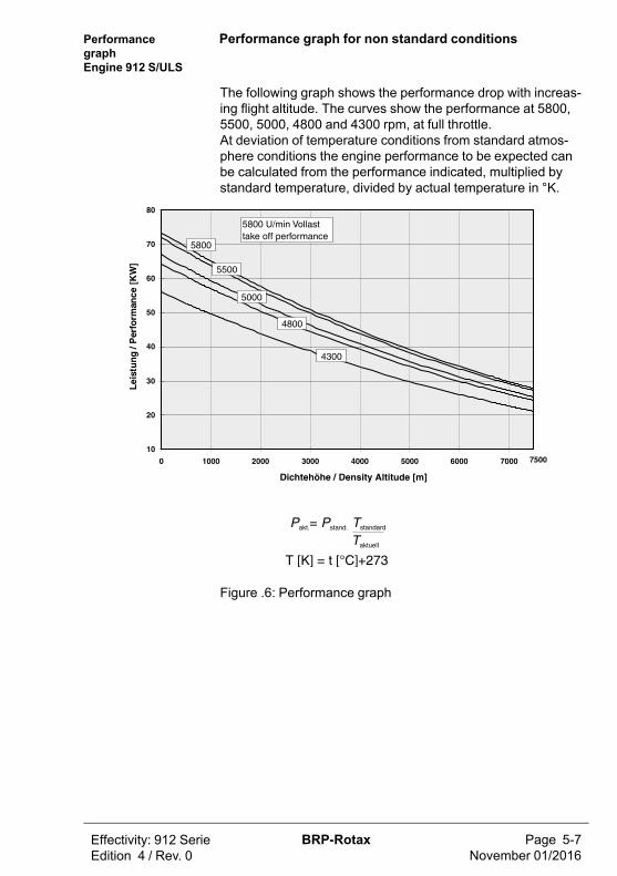
PerformancegraphEngine 912 S/ULS
Performance graph for non standard conditions
The following graph shows the performance drop with increas-ing flight altitude. The curves show the performance at 5800,5500, 5000, 4800 and 4300 rpm, at full throttle.At deviation of temperature conditions from standard atmos-phere conditions the engine performance to be expected canbe calculated from the performance indicated, multiplied bystandard temperature, divided by actual temperature in °K.
Figure .6: Performance graph

Page Notes-8November 01/2016
BRP-Rotax Effectivity: 912 SerieEdition 4 / Rev. 0
NOTES
6) Weights
Topics in this chapter
6.1 Weights – Engine...................................................................................16.2 Weight – Accessories.............................................................................1
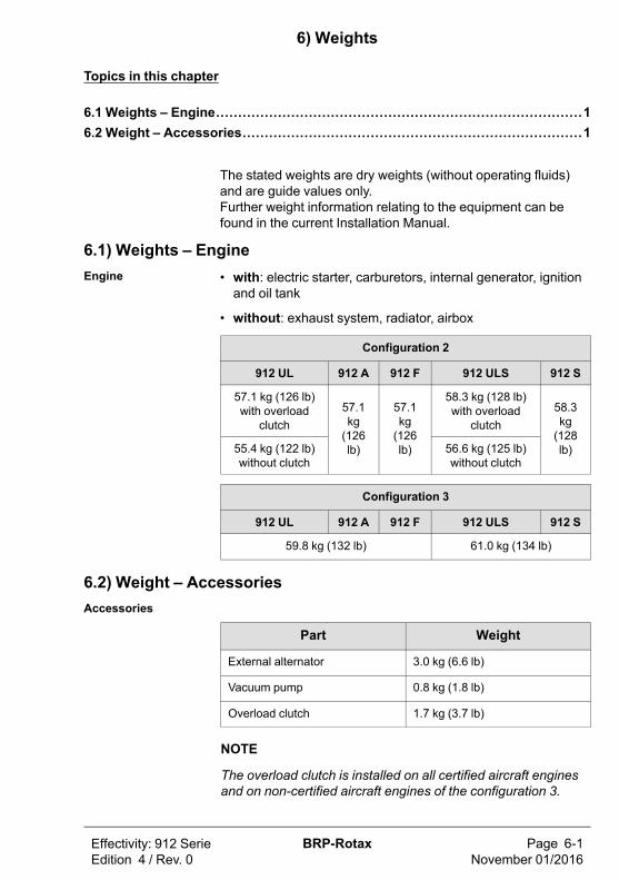
The stated weights are dry weights (without operating fluids)and are guide values only.Further weight information relating to the equipment can befound in the current Installation Manual.
6.1) Weights – EngineEngine • with: electric starter, carburetors, internal generator, ignition
and oil tank
• without: exhaust system, radiator, airbox
Configuration 2
912 UL 912 A 912 F 912 ULS 912 S
57.1 kg (126 lb)with overload
clutch57.1kg(126lb)
57.1kg(126lb)
58.3 kg (128 lb)with overload
clutch58.3kg(128lb)55.4 kg (122 lb)
without clutch56.6 kg (125 lb)without clutch
Configuration 3
912 UL 912 A 912 F 912 ULS 912 S
59.8 kg (132 lb) 61.0 kg (134 lb)
6.2) Weight – AccessoriesAccessories
Part Weight
External alternator 3.0 kg (6.6 lb)
Vacuum pump 0.8 kg (1.8 lb)
Overload clutch 1.7 kg (3.7 lb)
NOTE
The overload clutch is installed on all certified aircraft enginesand on non-certified aircraft engines of the configuration 3.
Effectivity: 912 SerieEdition 4 / Rev. 0
BRP-Rotax Page 6-1November 01/2016

Page Notes-2November 01/2016
BRP-Rotax Effectivity: 912 SerieEdition 4 / Rev. 0
NOTES
7) System Description
Topics in this chapter
7.1 Cooling system .....................................................................................27.2 Fuel system ..........................................................................................47.3 Lubrication system ................................................................................57.4 Electric system......................................................................................67.5 Propeller gearbox ..................................................................................7
Introduction This chapter of the Operator Manual contains information aboutthe general engine specification as well as a description ofcooling system, fuel system, lubrication system, electric systemand the propeller gearbox.The system description refers only to the engine and not to aspecific application in a particular aircraft. The aircraftmanufacturers Operators Manual is therefore definitive in termsof the operation of the engine, as it contains all the aircraftspecific instructions.
Effectivity: 912 SerieEdition 4 / Rev. 0
BRP-Rotax Page 7-1November 01/2016

7.1) Cooling systemSystem Overview The cooling system of the engine is designed for liquid cooling
of the cylinder heads and ram-air cooling of the cylinders. Thecooling system of the cylinder heads is a closed circuit with anexpansion tank.
Coolant flow The coolant flow is forced by a water pump, driven from thecamshaft, from the radiator to the cylinder heads. From the topof the cylinder heads the coolant passes on to the expansiontank. Since the standard location of the radiator is below enginelevel, the expansion tank located on the top of the engine allowsfor coolant expansion.
Expansion tank From the expansion tank the coolant is sucked thru the radiatorback to the water pump. Additionally the expansion tank isclosed by a pressure cap (with excess pressure valve and re-turn valve). At temperature rise of the coolant the excess pres-sure valve opens and the coolant will flow via hose atatmospheric pressure to the transparent overflow bottle. Whenthe engine is cooling down, the coolant will be sucked back intothe cooling circuit.
Coolant tempera-ture measuring
Reading are taken on measuring point of the hottest cylinderhead, depending on engine installation.
NOTE
The temperature sensors are located in cylinder head 2 and 3.
Page 7-2November 01/2016
BRP-Rotax Effectivity: 912 SerieEdition 4 / Rev. 0

Effectivity: 912 SerieEdition 4 / Rev. 0
BRP-Rotax Page 7-3November 01/2016
Figure .1: Cooling system
1 Expansion tank 2 Pressure cap
3 Radiator 4 Overflow bottle
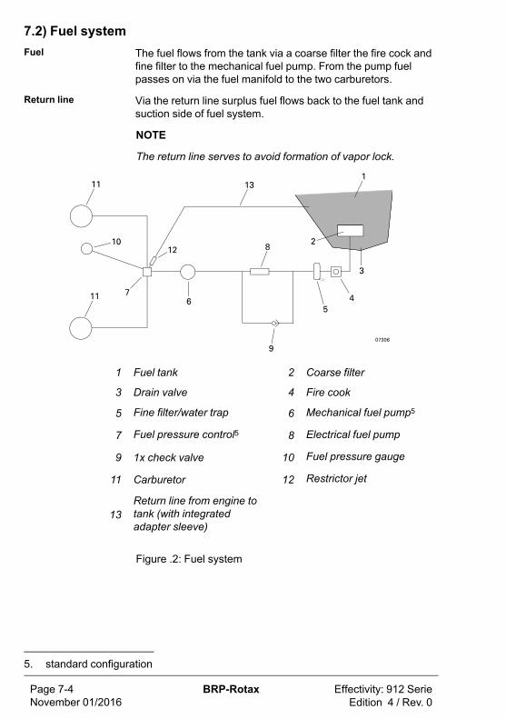
7.2) Fuel systemFuel The fuel flows from the tank via a coarse filter the fire cock and
fine filter to the mechanical fuel pump. From the pump fuelpasses on via the fuel manifold to the two carburetors.
Return line Via the return line surplus fuel flows back to the fuel tank andsuction side of fuel system.
NOTE
The return line serves to avoid formation of vapor lock.
1 Fuel tank 2 Coarse filter
3 Drain valve 4 Fire cook
5 Fine filter/water trap 6 Mechanical fuel pump5
7 Fuel pressure control5 8 Electrical fuel pump
9 1x check valve 10 Fuel pressure gauge
11 Carburetor 12 Restrictor jet
13Return line from engine totank (with integratedadapter sleeve)
Figure .2: Fuel system
Page 7-4November 01/2016
BRP-Rotax Effectivity: 912 SerieEdition 4 / Rev. 0
5. standard configuration
Effectivity: 912 SerieEdition 4 / Rev. 0
BRP-Rotax Page 7-5November 01/2016
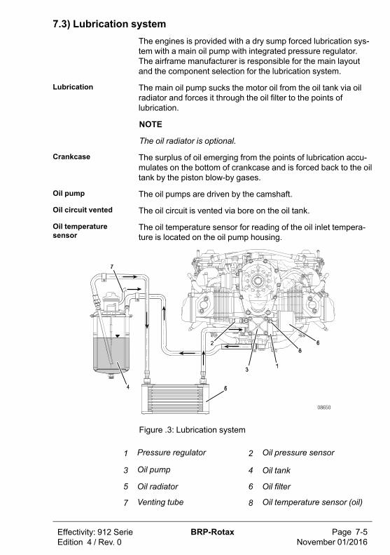
7.3) Lubrication systemThe engines is provided with a dry sump forced lubrication sys-tem with a main oil pump with integrated pressure regulator.The airframe manufacturer is responsible for the main layoutand the component selection for the lubrication system.
Lubrication The main oil pump sucks the motor oil from the oil tank via oilradiator and forces it through the oil filter to the points oflubrication.
NOTE
The oil radiator is optional.
Crankcase The surplus of oil emerging from the points of lubrication accu-mulates on the bottom of crankcase and is forced back to the oiltank by the piston blow-by gases.
Oil pump The oil pumps are driven by the camshaft.
Oil circuit vented The oil circuit is vented via bore on the oil tank.
Oil temperaturesensor
The oil temperature sensor for reading of the oil inlet tempera-ture is located on the oil pump housing.
Figure .3: Lubrication system
1 Pressure regulator 2 Oil pressure sensor
3 Oil pump 4 Oil tank
5 Oil radiator 6 Oil filter
7 Venting tube 8 Oil temperature sensor (oil)
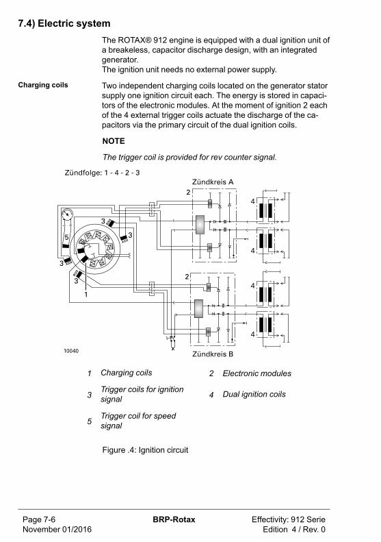
7.4) Electric systemThe ROTAX® 912 engine is equipped with a dual ignition unit ofa breakeless, capacitor discharge design, with an integratedgenerator.The ignition unit needs no external power supply.
Charging coils Two independent charging coils located on the generator statorsupply one ignition circuit each. The energy is stored in capaci-tors of the electronic modules. At the moment of ignition 2 eachof the 4 external trigger coils actuate the discharge of the ca-pacitors via the primary circuit of the dual ignition coils.
NOTE
The trigger coil is provided for rev counter signal.
B1/2
B3/4
A1/2
A3/4
1 Charging coils 2 Electronic modules
3Trigger coils for ignitionsignal 4 Dual ignition coils
5Trigger coil for speedsignal
Figure .4: Ignition circuit
Page 7-6November 01/2016
BRP-Rotax Effectivity: 912 SerieEdition 4 / Rev. 0

Effectivity: 912 SerieEdition 4 / Rev. 0
BRP-Rotax Page 7-7November 01/2016
7.5) Propeller gearboxReduction ratio For the engine type 912 one reduction ratio is available.
Reduction ratio 912 A/F/UL 912 S/ULS
crankshaft: propellershaft 2.27:1
2.43:12.43:1 (option)
Overload clutch Depending on engine type, certification and configuration thepropeller gearbox is supplied with or without an overload clutch.
NOTE
This overload clutch will prevent any undue load to the crank-shaft in case of ground contact of the propeller.
NOTE
The overload clutch is installed on serial production on all certi-fied aircraft engines and on the non-certified aircraft engines ofconfiguration 3.
Figure .5: Overload clutch
Fig. shows a propeller gearbox of configuration 2 with the inte-grated overload clutch.

Torsional shockabsorber
The design incorporates a torsional shock absorber. The shockabsorbing is based on progressive torsional cushioning due toaxial spring load acting on a dog hub.
Backlash On the gearbox version with overload clutch the design incorpo-rates a friction damped free play at the dogs to warrant properengine idling. Due to this backlash at the dogs a distinct torsion-al impact arises at start, stop and at sudden load changes, butdue to the built-in overload clutch it will remain harmless.
NOTE
This overload clutch will also prevent any undue load to thecrankshaft in case of ground contact of the propeller.
See Service Letter SL-912-015
Vacuum pump orhydraulicgovernor
Alternatively either a vacuum pump or a hydraulic governor forconstant speed propeller can be used. The drive is in each casevia the propeller reduction gear.
Page 7-8November 01/2016
BRP-Rotax Effectivity: 912 SerieEdition 4 / Rev. 0

8) Preservation and storage
Topics in this chapter
8.1 Engine preservation and storage .............................................................28.2 Engine back to operation ........................................................................3
Safety All checks to be carried out as specified in the currentMaintenance Manual Line (last revision).
mWARNING
Non-compliance can result in serious injuries or death!Only qualified staff (authorized by the Aviation Authorities) trainedon this particular engine, is allowed to carry out maintenance and
repair work.
NOTE
Other useful information for service and airworthiness of yourengine you'll find onwww.rotax-owner.com.
ATTENTION
Carry out all directives of Service Bulletins (SB), according totheir priority.Observe according Service Instructions (SI) and
Service Letter (SL).
Effectivity: 912 SerieEdition 4 / Rev. 0
BRP-Rotax Page 8-1November 01/2016

8.1) Engine preservation and storage
mWARNING
Risk of burnings and scalds! Hot engine parts!Conduct checks on the cold engine only!
Due to the special material of the cylinder wall, there is no needfor extra protection against corrosion for the ROTAX® aircraftengines. At extreme climatic conditions and for long out of serv-ice periods we recommends the following to protect the valveguides against corrosion:
Step Procedure
1 Operate the engine until the temperatures have stabilizedfor a period of 5 min (engine oil temperature between 50 to70 °C (122 to 160 °F).
2 Switch the engine OFF.
3 Allow the engine to cool down.
4 Change oil.
5 Remove the top spark plugs and spray all openings withcorrosion inhibiting oil.
6 Turn the propeller several times by hand in direction of theengine rotation, so that the corrosion inhibiting oil all nec-essary points reaches.
7 Install the spark plug in according the MaintenanceManual.
8 Close all openings on the cold engine, such as exhaustend pipe, venting tube, air filter etc. against entry of dirtand humidity.
9 Spray all steel external engine parts with corrosion inhibit-ing oil.
Page 8-2November 01/2016
BRP-Rotax Effectivity: 912 SerieEdition 4 / Rev. 0

Effectivity: 912 SerieEdition 4 / Rev. 0
BRP-Rotax Page 8-3November 01/2016
8.2) Engine back to operationIf preservation (including oil change) took place within a year ofstorage, oil renewal will not be necessary. For longer storageperiods repeat preservation annually.
Step Procedure
1 Remove all plugs and caps.
2 Clean spark plugs with plastic brush and solvent.
3 Reinstall.

Page Notes-4November 01/2016
BRP-Rotax Effectivity: 912 SerieEdition 4 / Rev. 0
NOTES
9) Supplement
Topics in this chapter
9.1 Form ....................................................................................................2
See Form
According to the regulation of EASA part 21 A.3 / FAR 21.3 themanufacturer shall evaluate field information and report to theauthority. In case of any relevant occurrences that may involvemalfunction of the engine, the form on the next page should befilled out and sent to the responsible ROTAX® authorizedaircraft engines distributor or their independent service center.
NOTE
The form is also available from the official ROTAX® AIRCRAFTENGINES Website in electronic version.
AuthorizedDistributor
Overview of ROTAX® authorized aircraft engines distributor ortheir independent service center.Refer to the official ROTAX® AIRCRAFT ENGINES Websitewww.FLYROTAX.com.
Effectivity: 912 SerieEdition 4 / Rev. 0
BRP-Rotax Page 9-1November 01/2016

9.1) Form
Figure .1: Form
Page 9-2November 01/2016
BRP-Rotax Effectivity: 912 SerieEdition 4 / Rev. 0
Effectivity: 912 SerieEdition 4 / Rev. 0
BRP-Rotax Page Index-1November 01/2016
Index
AAbbreviations ................................3Abnormal operation........................1After engine start ...........................8Auxiliary equipment......................14
BBefore engine start.........................5
CCold weather operation ................10Cooling system..............................2Cruising ........................................9cylinder designation .....................17
DDaily checks ..................................2Direction of rotation......................19
EElectric system ..............................6Engine back to operation ................3Engine components .....................17Engine preservation and storage.....2Engine shut-off ............................10Engine start ............................... 5–6Engine views ...............................17Exceeding cylinder headtemperature .................................3Exceeding engine speed ................3Exceeding of max. admissiblecoolant temperature .....................4Exceeding of max. admissiblecooling system temperature ..........3Exceeding oil temperature ..............4
FFire, Engine, compartment .............5Form.............................................2Fuel consumption ........................18Fuel system...................................4
GGeneral.........................................2
LList of effective pages.....................1Lubrication system.........................5
OOil pressure...................................5Oil pressure below minimum...........4Oil pressure below minimum -on ground ....................................5Operating limits (912 A/F/UL)..........2Operating limits(912 S/ULS) ...........5Operating media Fuel.....................9Operating media-Coolant ...............8Operating media-Lubricants..........10
PPerformance data ..........................2Pre-flight checks ............................5Propeller gearbox ..........................7
RRe-Start during flight ......................3
Page Index-2November 01/2016
BRP-Rotax Effectivity: 912 SerieEdition 4 / Rev. 0
SSafety notice ............................. 7, 9Standard version .........................14Start..............................................9
TTable of amendments.....................1Take-off.........................................9Technical data .............................18
Technical documentation ..............12Temperature..................................3Terms ...........................................3Trouble shooting ............................6Type description ..........................16
WWeight, Accessories.......................1Weights, Engine, Accessories.........1
Effectivity: 912 SerieEdition 4 / Rev. 0
BRP-Rotax Page List of Figures-1November 01/2016
List of Figures
Figure .1: Pos. 1: Engine serial number (1) ....................................2Figure .2: Side view engine (1)....................................................17Figure .3: Top view engine (1).....................................................17Figure .4: Front view engine (1) ..................................................18Figure .5: Normal direction of propeller rotation (engine)
(1) .............................................................................19Figure .1: Temperature range (2) ................................................ 11Figure .1: Expansion tank (3)........................................................3Figure .2: Overflow bottle (3) ........................................................3Figure .1: Performance graphs 912 A/F/UL (5)...............................2Figure .2: Values along propeller curve (5).....................................2Figure .3: Performance graphs 912 A/F/UL (5)...............................4Figure .4: Performance graphs Engine 912 S/ULS (5) ....................5Figure .5: Performance graphs Motor 912 S/ULS (5) ......................5Figure .6: Performance graph (5) ..................................................7Figure .1: Cooling system (7)........................................................3Figure .2: Fuel system (7).............................................................4Figure .3: Lubrication system (7)...................................................5Figure .4: Ignition circuit (7) ..........................................................6Figure .5: Overload clutch (7) .......................................................7Figure .1: Form (9).......................................................................2


Engine serial no.
Type of aircraft
Aircraft registration no.
Rotax® authorized distributor
FLYROTAX.COM® and TM are trademarks of BRP-Rotax GmbH & Co KG. © 2020 BRP-Rotax GmbH & Co KG. All rights reserved.