operators manual radio ohmstik - sensorlink
TRANSCRIPT

Operators Manual
Radio OhmstikRadio Linked Micro Ohmmeter
SensorLink® Corporation

Model 8-182Radio Ohmstik TransmitterModel 8-184 not pictured
Model 8-180Radio Ohmstik Display Unit
Model 6-182Radio Ohmstik Kitand Accessories

OPERATORS MANUALRadio OhmstikRadio Linked Live-Line Micro Ohmmeter
Table of Contents PageSpecifi cations 4
Safety Information 5
Theory of Operation 6
FCC and Industry Canada Statements 7
Cleaning and Transporting 7
Calculating Connector Resistance Ratio 8
Ratio Conditions and Actions 9
Radio Ohmstik Communication 10
Software Requrements and Installation 10
Communication with Software 11
Communication with Display Unit 12
Taking a Measurement 13
Reviewing the Measurement 14
Powering Off 14
Troubleshooting 15-16
Probes & Accessories 17-18
Battery Replacement 16
Warranty 19
Quality Assurance Back Cover
Available Stock Codes:
8-182 50HZ 8-182 60HZ 8-182 EURO
8-180 8-180 EURO 8-184 50HZ
8-184 60HZ 8-184 EURO

Page 4
Specifi cationsModel Number & Type 8-182 8-184
Type Standard Wide Jaw
Sensor Opening 2.5 in, 6.35 cm 3.86 in, 9.8 cm
Weight 2.3 lbs, 1.05 kg 4.0 lbs, 1.81 kg
Measurements
Amps 1-1400 A
Microohms 5-2500 μΩ
Accuracy
Amps ±1% 1 A
Microhms Absolute ±2% 2
Microhms Repeatability ±1% 2
Accuracy is diminished if the current is less than 15 amps 0-35kV and when current is less than 50 A while on 36-500kV
Range of Operation
Voltage Rated 500kV
Resolution
Amps 1.9-99 A 0.1 A
Amps 100-1400 A 1.0 A
Microhms 0-999 μΩ 1 μΩ
Frequency Actual frequency indicated on the unit
50Hz Calibrated 47 to 53Hz
60Hz Calibrated 57 to 63Hz
Radio
Frequency ISM 2.4 GHz
Power 63 mW, 10 mW in Europe & Japan
Range 150', (46 meters) Line of Sight, 120' (36.5 meters) in Europe & Japan
Mechanical
Battery 9 Volt Alkaline, 1 each per unit
Battery Life 6-8 Hours at 68°F or 20°C, 3-4 Hours at 32°F or 0°C
Detachable Probes Fused Probe or Adjustable Probe
Ambient Temperature -4 to +140° F, -20 to +60° C
Display Graphics LCD
Software Requirements Radio Ohmstik Software
System Requirements Windows XP, Vista, WIN 7, WIN 8, WIN 10
Hardware Requirements Minimum of two USB ports
EEC Standards Successfully passed international test standards indicated by CE
Page 5
Safety InformationRead all safety and instruction statements before using the product. Failing to follow the safety guidelines can cause severe injury or death.
Ohmstiks are designed for use on live, overhead lines with 0 to 500KV. All procedures ap pro pri ate for the line voltage are to be taken, including proper work techniques, equipment, and Personal Protection Equipment.
The Ohmstik should be used only by certifi ed personnel who have been trained for live-line, high voltage work by their organization.
Connecting the probes in a phase to phase, phase to ground, or any application where the voltage potential between the probes is more than 2.5 volts will cause damage to the instrument and create a system fault.
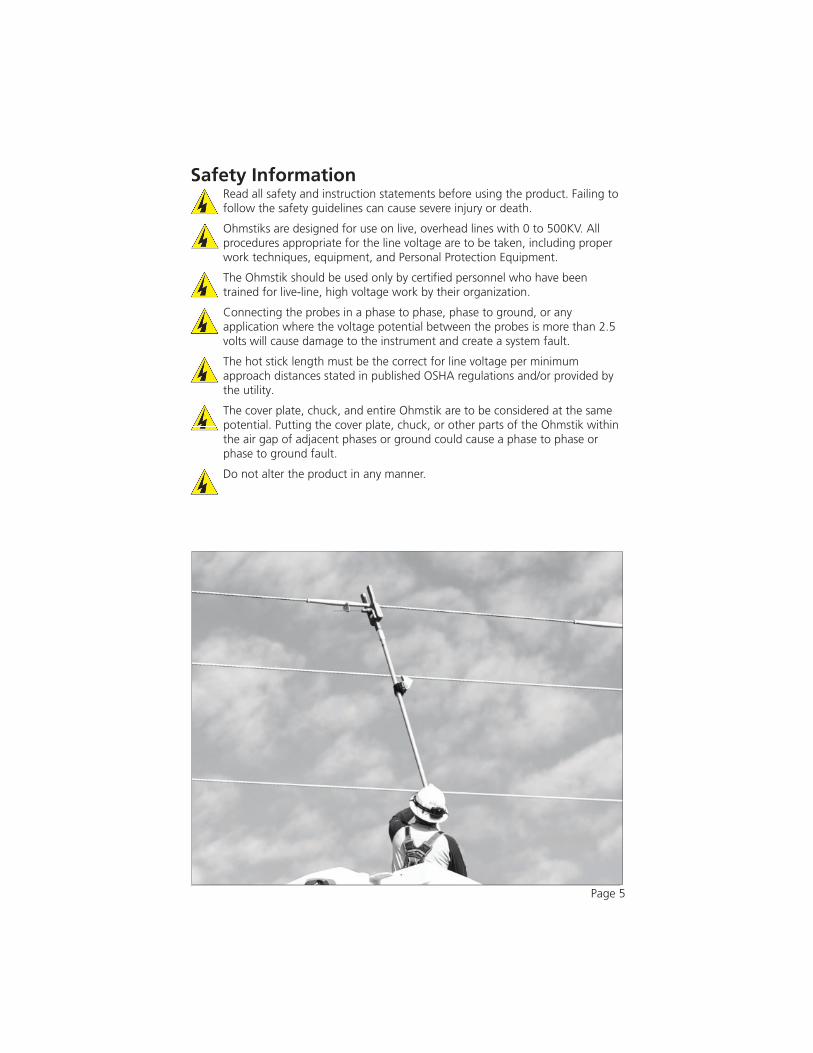
The hot stick length must be the correct for line voltage per minimum approach distances stated in published OSHA regulations and/or provided by the utility.
The cover plate, chuck, and entire Ohmstik are to be considered at the same potential. Putting the cover plate, chuck, or other parts of the Ohmstik within the air gap of adjacent phases or ground could cause a phase to phase or phase to ground fault.
Do not alter the product in any manner.

Theory of Op er a tionThe Radio Ohmstik Live-Line Micro Ohmmeter measures micro-ohm resistance on conductors, connectors, splices, and switching devices positioned directly on energized, high voltage lines. Resistance is the electrical condition of the connection and calculating the measurements into condition ratios provides defi nitive and actionable early warnings of a deteriorating fi tting. If the resistance of the fi tting is outside the normal range, the connection is deteriorating. A connection with resistance above the normal range is in a failure process, where the time to failure depends on how high the resistance is.
The Ohmstik is placed on a splice or connector so the connection under test is between the two electrodes. Measurement data is communicated to both the Remote Display and the Radio Ohmstik Software on the user's laptop. At the same time, the GPS device sends location data to the Software. When a valid measurement is received, the software writes the data to a comma separated (CSV) fi le. This combined data allows the user to map the location of the connector as well as the measurements to analyze its condition.
Page 6

FCC & Industry Canada StatementsUnited States of America and CanadaContains FCC ID: OUR-XBEEPROContains Model XBee-PRO Radio, IC: 4214A-XBEEPRO
The/XBee-PRO® RF Module has been certifi ed by the FCC for use with other products without any further certifi cation (as per FCC section 2.1091). Modifi cations not expressly approved by Digi could void the user's authority to operate the equipment.
This equipment has been tested and found to comply with the limits for a Class B digital device, pursuant to Part 15 of the FCC Rules. These limits are designed to provide reasonable protection against harmful interference in a residential installation. This equipment generates, uses and can radiate radio frequency energy and, if not installed and used in accordance with the instructions, may cause harmful interference to radio communications. However, there is no guarantee that interference will not occur in a particular installation.
If this equipment does cause harmful interference to radio or television reception, which can be determined by turning the equipment off and on, the user is encouraged to try to correct the interference by one or more of the following measures: Re-orient or relocate the receiving antenna, Increase the separation between the equipment and receiver, Connect equipment and receiver to outlets on different circuits, or Consult the dealer or an experienced radio/TV technician for help.
CleaningThe Radio Ohmstik should be cleaned by wiping with a silicone hot stick wipe to remove dirt, sand, and salt that will degrade the urethane housing.
TransportingThere are no special considerations for transporting this device.
Page 7
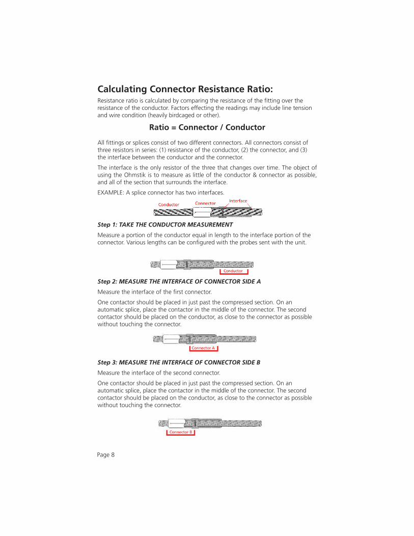
Calculating Connector Resistance Ratio:Resistance ratio is calculated by comparing the resistance of the fi tting over the resistance of the conductor. Factors effecting the readings may include line tension and wire condition (heavily birdcaged or other).
Ratio = Connector / Conductor
All fi ttings or splices consist of two different connectors. All connectors consist of three resistors in series: (1) resistance of the conductor, (2) the connector, and (3) the interface between the conductor and the connector.
The interface is the only resistor of the three that changes over time. The object of using the Ohmstik is to measure as little of the conductor & connector as possible, and all of the section that surrounds the interface.
EXAMPLE: A splice connector has two interfaces.
Step 1: TAKE THE CONDUCTOR MEASUREMENT
Measure a portion of the conductor equal in length to the interface portion of the connector. Various lengths can be confi gured with the probes sent with the unit.
Step 2: MEASURE THE INTERFACE OF CONNECTOR SIDE A
Measure the interface of the fi rst connector.
One contactor should be placed in just past the compressed section. On an automatic splice, place the contactor in the middle of the connector. The second contactor should be placed on the conductor, as close to the connector as possible without touching the connector.
Step 3: MEASURE THE INTERFACE OF CONNECTOR SIDE B
Measure the interface of the second connector.
One contactor should be placed in just past the compressed section. On an automatic splice, place the contactor in the middle of the connector. The second contactor should be placed on the conductor, as close to the connector as possible without touching the connector.
Page 8

Ratio Conditions and ActionsEvaluating any necessary actions can be completed once the ratios for the connector are calculated. The following table shows the suggested action based on maintaining the present load rating of the asset.
Resistance Ratio Condition of fi tting Action
0.3 to 1.0 Normal Connection: ServiceableNew connections are expected to be in the 0.3 to 0.8 range
None
1.01 to 1.2 Serviceable; PoorShows deterioration; Overloads & faults may deteriorate the connection
Re-inspect in one year, or after next fault
1.21 to 1.5 Serviceable; PoorShows deterioration; Overloads & faults may deteriorate the connection
Re-inspect in six months, or after next fault
1.51 to 2.0 Serviceable; Very poorHigh loads, overloads, or faults may deteriorate the connection
Schedule assetreplacement in less than three months
2.01 to 3.0 Bad; deterioration rate is increasingHigh loads, overloads, or faults may fail the connection. High tensions from cold weather or wind may initiate failure under normal loading
Schedule assetreplacement very soon
>3.0 FailingNormal loads, overloads, or faults may fail the connection; High tensions from cold weather or wind are likely to initiate failure under normal loading
Replace as soon as possible
*Actions required based on resistance ratios (Rfi tting / Rconductor)*These ratio conditions and actions are developed from fi eld measurements, manufacturer data, lab tests, failure analysis and understanding of deterioration mechanisms. This guideline may be modifi ed as fi eld and test data accumulates.
Calculating the Resistance of Power Tap Connectors:The Ohmstik will take resistance on other Full and Limited tension connectors. It is always best practice to take all three readings of the series and evaluate the condition with the above table. However, due to the build and size, it may not be possible to take all three readings in series. If evaluating based on a benchmark measurements, or comparison to a known good fi tting, a reading across the connector can be made. Factors effecting the reading may include line tension and wire condition (heavily birdcaged or other).
Page 9
Radio Ohmstik CommunicationThe user is able to view the measurement sets on both a Display Unit and on a laptop running Radio Ohmstik software. These communications may be used singly, or at the same time.
With Radio Ohmstik software and GPS, the following data may be written to the data fi le: Amps, Micro-Ohms, Date, Time, Comments, Latitude, and Longitude (with the GPS USB plugged into the laptop).
Communicating to the Display Unit: The Display Unit is designed to be attached to a hot stick or held by hand. The sensor transmits the live readings to the Display Unit via radio. This functionality allows the user to easily see readings were taken. Readings are not saved on the Display unit.
Communicating to the Laptop: With the Radio Ohmstik software loaded, and the radio adapter plugged in, the Sensor will transmit the data and readings to the laptop. The measurement set will automatically be saved as a .csv fi le for future review.
Radio Ohmstik System RequirementsOPERATING SYSTEM: Radio Ohmstik Software installs onto computers running Windows XP, VISTA, 7, 8, and 10. USB ports are needed for both GPS and Radio communication.
NETWORK INSTALLATION: This is a single user application and is not supported when installed onto a server.
INSTALLATION AUTHORITY: Installation will require administration rights. Computers managed by electric utility organizations often limit the programs that can be installed. If the user does not have admin rights they will need the assistance of the IT department to download the software.
USB PORT PERMISSIONS: The USB GPS and USB Radio have install programs that run the fi rst time connected. The user may have rights to install programs but may not be aware that the USB ports are locked on the PC. Please contact your network administrator for permission and instructions to complete the install if drivers are not installing automatically and need to be installed manually.
Softlink InstallationStep 1: Softlink Installer is available at www.sensorlink.com/products/ohmstik. Save the fi le to the desired location. The Radio Ohmstik .exe fi le will automatically begin the download when clicked.
Step 2: You must agree to the licensing agreement to proceed with the download.
Step 3: A dialog box will appear to let you know when the download is complete. Shortcut paths will automatically load during the install.
Page 10

Setup: Communication with SoftwareStep 1: Plug the 7-024 USB Radio and the 7-025 USB GPS devices into the laptop's USB ports. It will take several seconds for the computer to discover the devices
Step 2: Open the Radio Ohmstik Software
Step 3: The program starts by asking the user to select a fi le name and location to write the data. Note: The default File Name is a date and time code for the date and time the application is opened.
Step 4: Select Save; the Radio Ohmstik Dashboard will load and is ready for measurments
Page 11

Copyright 2011SensorLink F574 8XP 300
Firmware XXXNo Signal
Display Software Dashboard
Setup: Communication with Radio DisplayStep 1: If securing to a hot stick, place the Display Unit with the Velcro strap so the LCD display is visible while taking measurements.
Step 2: Press the function button on the Display Unit. The display will run through a startup sequence, ending with No Signal.
Setup: Radio Ohmstik Sensor Step 1: Attach the Probe to the back of the Radio Ohmstik. 7-081 XT Standard Probe, for 8-182 Transmitter 7-081 Standard Probe, for 8-184 Transmitter
The probe is de signed for use in close prox im i ty to ad ja cent phases or ground structures. See Safety Information on page fi ve. In the event of mak ing a phase to phase or phase to ground con nec tion, the Probe will break the connection.
Step 2: Press the function button on the Radio Ohmstik sensor. The LED will fl ash green when powered on.
Step 3: Both the Display and Software will indicate the Radio Ohmstik is ready to take measurements
Page 12
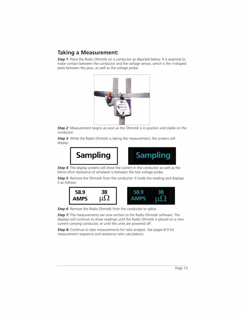
Taking a Measurement:Step 1: Place the Radio Ohmstik on a conductor as depicted below. It is essential to make contact between the conductor and the voltage sensor, which is the V-shaped plate between the jaws, as well as the voltage probe.
Step 2: Measurement begins as soon as the Ohmstik is in position and stable on the conductor.
Step 3: While the Radio Ohmstik is taking the measurement, the screens will display:
Step 4: The display screens will show the current in the conductor as well as the Micro-Ohm resistance of whatever is between the two voltage probe.
Step 5: Remove the Ohmstik from the conductor. It holds the reading and displays it as follows:
Step 6: Remove the Radio Ohmstik from the conductor or splice.
Step 7: The measurements are now written to the Radio Ohmstik software. The displays will continue to show readings until the Radio Ohmstik is placed on a new current carrying conductor, or until the units are powered off.
Step 8: Continue to take measurements for ratio analysis. See pages 8-9 for measurement sequence and resistance ratio calculations.
Page 13

Page 14
Power Off the Radio OhmstikPress and hold the Function Button on the Display Unit until the LCD goes blank
or Press and hold the Function Button on the Radio Ohmstik until the LED goes off. Either of these actions will power off itself and the accompanied device. The Radio Ohmstik will power off by itself if left inactive for 20 minutes.
Collecting Measurements in SoftwareStep 1: The Radio Ohmstik software will display the completed measurement and GPS location on the Dashboard.
Step 2: The data will automatically be written to a comma-separated values (CSV) fi le when the Radio Ohmstik is removed from the conductor.
Step 3: A comment may be added before the reading is taken. Any comment written will be a part of the record for the next reading and will save for future lines. If the comment is not needed delete it on the record before taking the next measurement.
Step 4: To review the data, open the saved CSV fi le in any spreadsheet or word processing application.
Note: Opening the CSV fi le while the dashboard is open, will stop the recording of readings. The number of readings will be recorded on the dashboard but the readings will not be stored.

Troubleshooting and Error Messages:“No Contact”The Radio Ohmstik reads current but not micro-ohms:
This indicates one of the two voltage sensors is not making contact. Use the rough edges of the probe to clean corrosion from the conductor and re-take the measurement. Make certain both voltage sensors are making contact. The fi tting cannot be covered. See page 13 for instructions on Taking a Measurement.
“Poor Contact”The Radio Ohmstik reads current but not micro-ohms:
There is poor contact on the conductor with one of the voltage contacts. Provide fi ve seconds to measure, while the Radio Ohmstik is held stationary with both voltage probes securely on the line.
“Reading Ohms”The following message indicates the current measurement was completed before the resistance measurement could be completed:
Provide fi ve seconds to measure, while the Radio Ohmstik is held stationary with both voltage probes securely on the line.
“Unable To Measure”The Radio Ohmstik uses logic to know when it is on a conductor by looking for a stable load:
Hold the Radio Ohmstik fi rmly on the line for at least fi ve seconds. The Ohmstik samples the line three times every 100 milliseconds. If it cannot fi nd three consecutive reads that are within tolerance it will display “Unable To Measure”.
Page 15

“Exceeds 1400 Amps”The Radio Ohmstik limits the maximum current to 1400 Amps:
The Radio Ohmstik is not specifi ed to measure above 1400A.
Battery ReplacementThe Radio Ohmstik system is powered by two 9V batteries, one in the Radio Ohmstik and one in the Display. The expected battery life for both units is 6 to 8 hours at 68° F or 20° C. The expected life declines in colder environments. At 32°F or 0°C it is reduced 3 to 4 hours.
Note: It is recommended fresh batteries be installed prior to operation each day. Always replace both batteries.
To replace the battery, remove the four screws on the battery cover at the rear of the unit. Carefully insert a screwdriver blade in the notch and pry the cover out, being careful not to damage the cover seal. Pull the battery out of the compartment and separate the battery from the battery connector. To avoid breaking the battery leads do not pull on the battery only. Install a fresh battery and reinsert the battery in its compartment. Do not pinch the wires between the battery and compartment; put wires in slot above the battery. Reinstall the cover by gently pressing it into place while pulling out on the edges of the compartment, and reinstall the four cover screws. Take care to avoid over tightening the screws. Always reuse the screws provided and do not damage or lose the O-ring seal on each screw.
Page 16
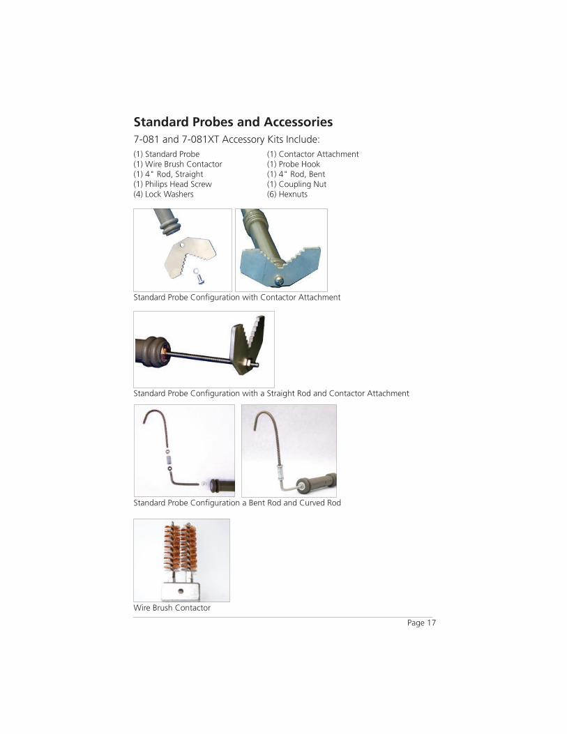
Standard Probe Confi guration with Contactor Attachment
Standard Probes and Ac ces so ries 7-081 and 7-081XT Accessory Kits Include:(1) Standard Probe (1) Contactor Attachment (1) Wire Brush Contactor (1) Probe Hook(1) 4" Rod, Straight (1) 4" Rod, Bent(1) Philips Head Screw (1) Coupling Nut(4) Lock Washers (6) Hexnuts
Standard Probe Confi guration with a Straight Rod and Contactor Attachment
Standard Probe Confi guration a Bent Rod and Curved Rod
Page 17
Wire Brush Contactor

7-081 ADJ Adjustable Probe Accessory Kit Includes:The Adjustable probe is designed for any measurement where the distance to be measured is less than 12 inches. This probe will adjust from 4 to 13 inches.
Adjustable Probe Kit includes:(1) Adjustable Probe (1) Wire Brush Contactor(1) Contactor Attachment (2) Hex Nuts
Other Replacement Accessories
The Universal Adapter allows the user to adjust the Ohmstik Transmitter at com pound an gles. This is a useful adapt er when working from the ground on com plex ap pa ra tus.
7-050 Universal Adapter
Page 18
Adjustable Probe with Contactor Attachment
7-025 USB GPS Adapter 7-051 Carrying Case 7-024 USB Radio Adpater

Page 19
SensorLink Corporation Warranty
SensorLink Corporation warrants each instrument it man u fac tures to be free from defects in materials and workmanship under nor mal use and service for the period of one year after date of ship ment. Within this period, SensorLink Corporation agrees to re pair or replace, at SensorLink Corporation’s option, any instrument that fails to perform as specifi ed. This Warranty shall not apply to any in stru ment that has been:
1 Repaired, worked on, or altered, including removal of the front panel, by persons un au tho rized by SensorLink Corporation in such a manner as to injure, in SensorLink Corporation’s sole judg ment, the per for mance, sta bil i ty, or reliability of the in stru ment;
2 Sub ject ed to misuse, negligence, or accident; or
3 Connected, installed, adjusted, or used otherwise than in ac cor dance with the instructions furnished by SensorLink Corporation.
This Warranty is in lieu of any other warranty, expressed or implied. SensorLink Cor-poration reserves the right to make any chang es in the design or construction of its in stru ments at any time, with out incurring any obligation to make any change what ev er in units previously de liv ered.
If a failure occurs, contact the manufacturer for a Return Authorization and instructions for return shipment. This war ran ty con sti tutes the full understanding of the man u fac- tur er and buy er, and no terms, conditions, understanding, or agree ment pur port ing to modify or vary the terms hereof shall be binding unless here af ter made in writing and signed by an authorized offi cial of SensorLink Corporation.

Quality Assurance Certifi cationRadio Ohmstik
Transmitter Models 8-182 and 8-184Display Unit Model 8-180
SensorLink Corporation certifi es that its calibration measurements are traceable to the National Institute of Standards and Technology (NIST), to the extent allowed by the Institute's calibration facility, and to the calibration facilities of other International Standards Organization members.
This document certifi es the following Radio Ohmstik was tested at the SensorLink Corporation High Voltage Lab o ra to ry, Ferndale, WA, USA to the ap pro pri ate standard and comply with the re quire ments of that stan dard.
Sensor; Model Number: ______________________________________
Serial Number: _______________________________________________
Display Unit; Model Number: __________________________________
Serial Number: _______________________________________________
I hereby certify that the Radio Ohmstik listed above has passed all tests de fi ned in the Sensorlink Corporation standard. I also certify that I have reviewed the standard and test pro ce dure and that they are suffi cient in determining compliance with the stan dard.
Signed: _____________________________________________________
Date: _______________________________________________________
1360 Stonegate Way Ferndale, WA 98248 USA phone: 360/595.1000 fax: 360/595.1001 www.sensorlink.com
Form No: SALE-Manual Template OHMSTIK-008 REV: V04Date: 01/2020Manual Stock Code No: DOPM-818-200Information contained in this document is subject to change without notice. Product specifi cation may change. Contact your SensorLink representative for the most current product information. © 2019 by SensorLink. All rights reserved.
Made in the USA.
SensorLink® Cor po ra tion