operator's manual model ppf-210 - echo usa...operator's manual model ppf-210 warning read...
TRANSCRIPT

POWER PRUNERTM
OPERATOR'S MANUAL 1
Power PrunerTM
Operator's Manual
MODEL PPF-210
WARNINGRead rules for safe operation and instructions carefully. ECHO provides an Operator'sManual and a Safety Manual. Both must be read and understood for proper and safeoperation. Failure to do so could result in serous injury.
X75000961102/07
X7502307501

2
Copyright© 2007 By Echo, IncorporatedAll Rights Reserved.
INTRODUCTION
Welcome to the ECHO family. This ECHO product was designed and manufactured to provide long life and on-the-jobdependability. Read and understand this manual and the SAFETY MANUAL you found in the same package. You willfind both easy to use and full of helpful operating tips and SAFETY messages.
THE OPERATOR'S MANUALRead and understand this manual before operation. Keep it in a safeplace for future reference. It contains specifications and information foroperation, starting, stopping, maintenance, storage, and assemblyspecific to this product.
THE SAFETY MANUALRead and understand this manual before operation. Keep it in a safeplace for future reference. It explains possible hazards involved with theuse of Power PrunerTM and what measures you should take to make theiruse safer.
TABLE OF CONTENTSIntroduction ............................................................... 2
- The Operator's Manual ........................................ 2- The Safety Manual ............................................. 2
Safety ......................................................................... 3- Manual Safety Symbols and Important
Information ......................................................... 3- International Symbols ......................................... 3- Personal Condition and Safety Equipment ......... 4- Kickback ............................................................. 6- Equipment ........................................................... 7
Emission Control ........................................................ 7Description ................................................................ 8Contents .................................................................. 10Assembly ................................................................. 10
- Cutting Attachment to Drive Shaft Installation 10- 3-Foot Extension Installation ............................ 11- Saw Chain Tension Adjustment ....................... 11
Pre-Operation ........................................................... 12- Fuel ................................................................... 12- Lubricating the Guide Bar and Saw Chain ........ 14- Adjusting Automatic Oiler ................................ 14- Starting Cold Engine ......................................... 15- Starting Warm Engine ....................................... 16- Stopping Engine ............................................... 16- Pruning Techniques ......................................... 17
Maintenance ............................................................ 17- Skill Levels ........................................................ 17- Maintenance Intervals ...................................... 18- Air Filter ............................................................ 19- Fuel Filter .......................................................... 19- Spark Plug ......................................................... 20- Cooling System Cleaning .................................. 20- Exhaust System ................................................. 22- Carburetor Adjustment ..................................... 23- Guide Bar and Saw Chain Replacement ............ 24- Filing Saw Chain ............................................... 26
Troubleshooting ...................................................... 27Storage ..................................................................... 28Specifications ........................................................... 29Servicing Information ............................................... 32
- Parts/Serial Number .......................................... 32- Service .............................................................. 32- ECHO Consumer Product Support .................... 32- Warranty Card .................................................. 32- Additional or Replacement Manuals ................ 32
Specifications, descriptions and illustrative material inthis literature are as accurate as known at the time ofpublication, but are subject to change without notice.Illustrations may include optional equipment andaccessories, and may not include all standardequipment.

POWER PRUNERTM
OPERATOR'S MANUAL 3SAFETYMANUAL SAFETY SYMBOLS AND IMPORTANT INFORMATION
HotSurface
Symboldescription/application Symbol form/shape
Symboldescription/applicationSymbol form/shape
Read and understandOperator's Manual.
Wear eyes, ears andhead protection
Fuel and oil mixture
Finger Severing
Safety/Alert
Avoid all power lines.This unit is not insu-lated against electri-
cal current.
Do not operate closerthan 15 M (50 ft.) fromelectrical haz-ards.
Keep bystanders atleast 15 meters(50 feet) away.
Plan retreat pathfrom fallingobjects.
Wear handprotection. Use
two handed.
DO NOT SMOKENEAR FUEL.
INTERNATIONAL SYMBOLSSymbol
description/application Symbol form/shapeSymbol
description/applicationSymbol form/shape
Carburetor adjustment- Idle speed
Carburetor adjustment- High speed mixture
Emergency stop
Carburetor adjustment- Low speed mixture
DO NOT ALLOWFLAMES OR
SPARKS NEARFUEL.
Wear slip resistantfoot wear.
IgnitionON/OFF
CHAINLUBRICATION
Primer bulb
Choke Control"Cold Start"
Position(Choke Closed)
Choke Control"Run"
Position(Choke Open)
WARNINGThe safety alert symbol accompanied by the word“WARNING” calls attention to an act or conditionwhich CAN lead to serious personal injury or deathif not avoided.
CIRCLE AND SLASH SYMBOLThis symbol means the specific actionshown is prohibited. Ignoring theseprohibitions can result in serious or fatalinjury.
CAUTIONThe safety alert symbol accompanied by the word“CAUTION” calls attention to an act or conditionwhich may lead to minor or moderate personal injuryif not avoided.
NOTEThis enclosed message provides tips for use, careand maintenance of the unit.
IMPORTANTThe enclosed message provides informationnecessary for the protection of the unit.
DANGERThe safety alert symbol accompanied by the word“DANGER” calls attention to an act or conditionwhich WILL lead to serious personal injury or deathif not avoided.
Throughout this manual and on the product itself, you will find safety alerts and helpful, informational messagespreceded by symbols or key words. The following is an explanation of those symbols and key words and what theymean to you.
4
Physical ConditionYour judgment and physical dexterity may not be good:
• if you are tired or sick,• if you are taking medication,• if you have taken alcohol or drugs.
Operate unit only if you are physically and mentally well.
Eye ProtectionWear eye protection that meets ANSI Z87.1 or CErequirements whenever you operate the unit
Face and Head ProtectionWhen trimming overhead, always wear head protectionmeeting ANSI Z89.1 or CE requirements with a full faceshield. Head protection with full face shield will helpprotect you from falling branches and debris.
Hand ProtectionWear no-slip, heavy duty work gloves to improve yourgrip on the unit handles. Gloves also reduce the transmis-sion of machine vibration to your hands.
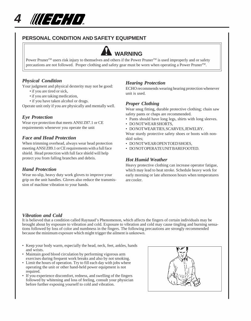
Vibration and ColdIt is believed that a condition called Raynaud’s Phenomenon, which affects the fingers of certain individuals may bebrought about by exposure to vibration and cold. Exposure to vibration and cold may cause tingling and burning sensa-tions followed by loss of color and numbness in the fingers. The following precautions are strongly recommendedbecause the minimum exposure which might trigger the ailment is unknown.
• Keep your body warm, especially the head, neck, feet, ankles, handsand wrists.
• Maintain good blood circulation by performing vigorous armexercises during frequent work breaks and also by not smoking.
• Limit the hours of operation. Try to fill each day with jobs whereoperating the unit or other hand-held power equipment is notrequired.
• If you experience discomfort, redness, and swelling of the fingersfollowed by whitening and loss of feeling, consult your physicianbefore further exposing yourself to cold and vibration.
PERSONAL CONDITION AND SAFETY EQUIPMENT
WARNINGPower PrunerTM users risk injury to themselves and others if the Power PrunerTM is used improperly and or safetyprecautions are not followed. Proper clothing and safety gear must be worn when operating a Power PrunerTM.
Hearing ProtectionECHO recommends wearing hearing protection wheneverunit is used.
Proper ClothingWear snug fitting, durable protective clothing; chain sawsafety pants or chaps are recommended.• Pants should have long legs, shirts with long sleeves.• DO NOT WEAR SHORTS,• DO NOT WEAR TIES, SCARVES, JEWELRY.Wear sturdy protective safety shoes or boots with non-skid soles;• DO NOT WEAR OPEN TOED SHOES,• DO NOT OPERATE UNIT BAREFOOTED.
Hot Humid WeatherHeavy protective clothing can increase operator fatigue,which may lead to heat stroke. Schedule heavy work forearly morning or late afternoon hours when temperaturesare cooler.

POWER PRUNERTM
OPERATOR'S MANUAL 5
DANGERAll over head electrical conductors and communications wires canhave electricity flow with high voltages. This unit is not insulatedagainst electrical current. Never touch wires directly or indirectlywhen pruning, otherwise serious injury or death may result.
WARNINGDo not operate this product indoors or in inadequately ventilatedareas. Engine exhaust contains poisonous emissions and can causeserious injury or death.
Read the Manuals• Provide all operators of this equipment with the Operator's Manual,
and instructions for safe operation.
Clear the Work Area• Spectators and fellow workers must be warned, and children and
animals prevented from coming nearer than 15 m (50 ft.) while the unitis in use.
Use Proper Clothing & Equipment• Always wear head protection with full face shield to help protect
against falling branches and debris.
Keep A Firm Grip• Grip Power PrunerTM with both hands with thumbs and fingers
encircling the handle, and shaft tube.
Repetitive Stress InjuriesIt is believed that overusing the muscles and tendons of the fingers, hands, arms and shoulders may cause soreness,swelling, numbness, weakness and extreme pain in those areas. Certain repetitive hand activities may put you at a highrisk for developing a Repetitive Stress Injury (RSI). An extreme RSI condition is Carpal Tunnel Syndrome (CTS), whichcould occur when your wrist swells and squeezes a vital nerve that runs through the area. Some believe that prolongedexposure to vibration may contribute to CTS. CTS can cause severe pain for months or even years.
To reduce the risk of RSI/CTS, do the following:• Avoid using your wrist in a bent, extended or twisted position.
Instead try to maintain a straight wrist position. Also, when grasping,use your whole hand, not just the thumb and index finger.
• Take periodic breaks to minimize repetition and rest your hands.• Reduce the speed and force with which you do the repetitive move-
ment.• Do exercises to strengthen the hand and arm muscles.• Immediately stop using all power equipment and consult a doctor if
you feel tingling, numbness or pain in the fingers, hands, wrists orarms. The sooner RSI/CTS is diagnosed, the more likely permanentnerve and muscle damage can be prevented.
6
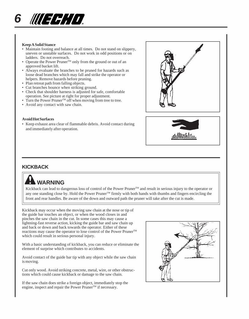
Keep A Solid Stance• Maintain footing and balance at all times. Do not stand on slippery,
uneven or unstable surfaces. Do not work in odd positions or onladders. Do not overreach.
• Operate the Power PrunerTM only from the ground or out of anapproved bucket lift.
• Always evaluate the branches to be pruned for hazards such asloose dead branches which may fall and strike the operator orhelpers. Remove hazards before pruning.
• Plan retreat path from falling objects.• Cut branches bounce when striking ground.• Check that shoulder harness is adjusted for safe, comfortable
operation. See picture at right for proper adjustment.• Turn the Power PrunerTM off when moving from tree to tree.• Avoid any contact with saw chain.
Avoid Hot Surfaces• Keep exhaust area clear of flammable debris. Avoid contact during
and immediately after operation.
WARNINGKickback can lead to dangerous loss of control of the Power PrunerTM and result in serious injury to the operator orany one standing close by. Hold the Power PrunerTM firmly with both hands with thumbs and fingers encircling thefront and rear handles. Be aware of the down and outward path the pruner will take after the cut is made.
KICKBACK
Kickback may occur when the moving saw chain at the nose or tip ofthe guide bar touches an object, or when the wood closes in andpinches the saw chain in the cut. In some cases this may cause alightning-fast reverse action, kicking the guide bar and saw chain upand back or down and back towards the operator. Either of thesereactions may cause the operator to lose control of the Power PrunerTM
which could result in serious personal injury.
With a basic understanding of kickback, you can reduce or eliminate theelement of surprise which contributes to accidents.
Avoid contact of the guide bar tip with any object while the saw chainis moving.
Cut only wood. Avoid striking concrete, metal, wire, or other obstruc-tions which could cause kickback or damage to the saw chain.
If the saw chain does strike a foreign object, immediately stop theengine, inspect and repair the Power PrunerTM if necessary.

POWER PRUNERTM
OPERATOR'S MANUAL 7
PRODUCT EMISSION DURABILITYThe 300 hour emission durability compliance period is the time span selected by the manufacturer certifying theengine emissions output meets applicable emissions regulations, provided that approved maintenance proceduresare followed as listed in the Maintenance Section of this manual.
An Emission Control Label is located on the engine. (This is an EXAMPLE ONLY, information on label varies by engineFAMILY).
EQUIPMENT
WARNINGSerious injury may result from the use of non approved guide bar and saw chain combinations. ECHO, INC. will notbe responsible for the failure of cutting devices or accessories which have not been tested and approved by ECHOfor use with this unit. Read and comply with all safety instructions listed in this manual.
• Check unit for loose/missing nuts, bolts, and screws. Tighten and/or replace as needed.• Inspect fuel lines, tank, and area around carburetor for fuel leaks. DO NOT operate unit if leaks are found.
Guide Bar and Saw Chain• Check that the cutting attachment, guide bar, and saw chain is firmly attached and in safe operating condition.• Use only one Echo-approved extension on the pruner.• Do not hit rocks, stones, tree stumps, and other foreign objects with the saw chain.• Do not cut into the ground with the saw chain.• If cutting attachment end strikes an obstruction, stop engine immediately and inspect saw chain for damage.• Do not operate with a dull, fractured, or discolored saw chain.• Remove all foreign objects from work area.• Always cover the guide bar and saw chain with guide bar cover during transportation and for storage.
EMISSION CONTROLEPA Phase 2 / C.A.R.B. TIER IIIThe emission control system for the engine is EM/TWC (Engine Modification and 3-way Catalyst) and for the fuel tankthe Control System is EVAP (Evaporative Emissions). Evaporative emission may be applicable to California models only.
IMPORTANT ENGINE INFORMATIONENGINE FAMILY: 7EHXS.0214KF DISPLACEMENT: 21.2 CC
EMISSION COMPLIANCE PERIOD : 300 HRS.
THIS ENGINE MEETS U.S. EPA PHASE 2 EMISSION
REGULATIONS FOR SMALL NONROAD ENGINES. REFER TO
OWNER'S MANUAL FOR MAINTENANCE SPECIFICATIONS
AND ADJUSTMENTS.
IMPORTANT ENGINE INFORMATIONENGINE FAMILY: 7EHXS.0214KF DISPLACEMENT: 21.2 CC
EMISSION COMPLIANCE PERIOD : 300 HRS.
THIS ENGINE MEETS U.S. EPA PH2 EXH AND 2007 AND
LATER CALIFORNIA EXH AND EVAP EMISSION REGULA-
TIONS FOR S.O.R.E.. REFER TO OWNER'S MANUAL FOR
MAINTENANCE SPECIFICATIONS AND ADJUSTMENTS.

8
1
2
8
7
3
4
5
6
9
10
11
12
14
16
17
18
19
20
21
22
15
13
23
DESCRIPTIONLocate this safety decal on your unit. Make sure the decals are legible and that you understand and follow the instruc-tions on them. If a decal cannot be read, a new one can be ordered from your ECHO dealer. See PARTS ORDERINGinstructions for specific information.
Engine Cover
P/N 89016022660
P/N 89016006361Hot Decal (near muffler)

POWER PRUNERTM
OPERATOR'S MANUAL 9
1. POWER HEAD - Includes the Engine, Clutch, Fuel System, Ignition System and Starter.
2. REAR HANDLE ASSEMBLY - Rear (right hand) handle.
3. THROTTLE TRIGGER LOCKOUT - This lever must be held during starting. Operation of the throttle trigger isprevented unless throttle trigger lockout lever is engaged.
4. STOP SWITCH - Mounted on top of rear handle assembly. Move switch forward to run, back to stop.
5. STRAP HOOK - Used to secure unit to shoulder harness.
6. FRONT HANDLE - Cushioned grip for left hand.
7. CUTTING ATTACHMENT - Sealed, gear ratio is 1.5:1 reduction.
8. AUTOMATIC OILER ASSEMBLY - Self oiling. Use high quality, low viscosity, non detergent bar and chain oil.
9. GUIDE BAR - 254 mm (10 inch) Bar.
10. SAW CHAIN - 91, 9.53mm (3/8 inch) pitch, 0.050 gauge low profile Oregon® saw chain. Runs approximately 609.6m/min. (2000 ft/min) at full throttle.
11. CUTTING SHOE - Used to capture and stabilize branch while cutting. Place cutting shoe against branch, accelerateand lower saw chain into branch.
12. THROTTLE TRIGGER - Spring loaded to return to idle when released. During acceleration press throttle triggergradually for best operating technique.
13. SHOULDER HARNESS - An adjustable strap that suspends the unit from the operator.
14. RECOIL STARTER HANDLE - Pull handle slowly until recoil starter engages, then quickly and firmly. When enginestarts return handle slowly. DO NOT let handle snap back or damage will occur.
15. SPARK ARRESTOR - CATALYTIC MUFFLER / MUFFLER -The muffler or catalytic muffler controls exhaust noiseand emission. The spark arrestor screen prevents hot, glowing particles of carbon from leaving the muffler. Keepexhaust area clear of flammable debris.
16. FUEL TANK - Contains fuel and fuel filter.
17. FUEL TANK CAP - Covers and seals fuel tank opening.
18. PURGE BULB - Pumping purge bulb before starting engine draws fresh fuel from the fuel tank, purging air from thecarburetor. Pump purge bulb until fuel is visible and flows freely in the clear fuel tank return line. Pump purge bulban additional 4 or 5 times.
19. AIR CLEANER ASSEMBLY - Contains replaceable air filter element.
20. CHOKE - Located above air cleaner housing. Move lever to starting position ( ) (close choke) and back to runposition ( ) (open choke).
21. SPARK PLUG - Provides spark to ignite fuel mixture.
22. TOP GUARD - Protects arm from hot engine.
23. GUIDE BAR COVER - Used to cover guide bar and saw chain during transport and storage. Remove guide barcover before using unit.

10
WARNINGSaw chain is sharp! Always wear gloves when handling cuttingattachment, otherwise serious personal injury may result.
1. Loosen the (4) four lower bolts (A) on the cutting attachment, andremove location bolt (B).
2. Slide the cutting attachment onto the shaft housing until the holein the neck of the cutting attachment is aligned with the hole (C) inthe housing. (It may be necessary to rotate the saw chain slightlyto align the internal pinion and drive shaft.)
3. Insert location bolt (B) into hole (C) and tighten to snug.
4. Tighten bolts (A), clamping the cutting attachment onto thehousing.
CONTENTSDue to packaging restriction the ECHO product you have purchased requires some assembly.
After opening the carton, check for damage. Immediately notify your retailer or ECHO Dealer of damaged or missingparts. Use the contents list to check for missing parts.
__ Power Head/Drive Shaft Assembly__ Cutting Attachment__ Operator's Manual__ Safety Manual__ Warranty Registration Card__ Warranty Statement__ 1, T-Wrench (Combination screwdriver/spark plug socket)__ 1, 4 mm Hex Wrench__ Safety Glasses__ Echo Power Blend TM 2-stroke oil sample__ Shoulder Harness__ Guide Bar Cover
ASSEMBLY
For your convenience the Power PrunerTM has been shipped with the power head attached and throttle linkage assembled.We recommend the power head remain attached to the drive shaft and housing at all times.
Tools Required: 3 mm Hex Wrench, Screwdriver, T-wrench
Parts Required: Power Head/Drive Shaft, Cutting Attachment,3-foot Extension (Optional) P/N 99946400010
CUTTING ATTACHMENT TO DRIVE SHAFT INSTALLATION
B
C
A A
POWER PRUNERTM
OPERATOR'S MANUAL 11
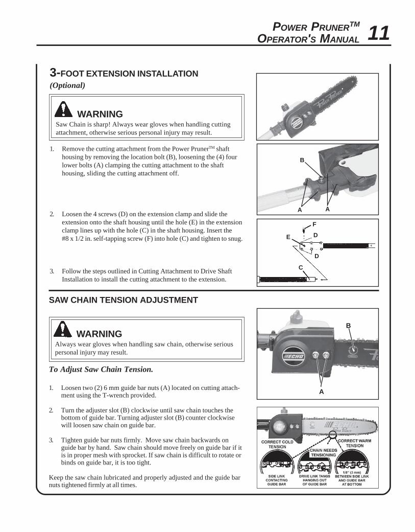
3-FOOT EXTENSION INSTALLATION(Optional)
WARNINGSaw Chain is sharp! Always wear gloves when handling cuttingattachment, otherwise serious personal injury may result.
1. Remove the cutting attachment from the Power PrunerTM shafthousing by removing the location bolt (B), loosening the (4) fourlower bolts (A) clamping the cutting attachment to the shafthousing, sliding the cutting attachment off.
2. Loosen the 4 screws (D) on the extension clamp and slide theextension onto the shaft housing until the hole (E) in the extensionclamp lines up with the hole (C) in the shaft housing. Insert the#8 x 1/2 in. self-tapping screw (F) into hole (C) and tighten to snug.
3. Follow the steps outlined in Cutting Attachment to Drive ShaftInstallation to install the cutting attachment to the extension.
A A
B
D
D
C
E
F
B
A
SAW CHAIN TENSION ADJUSTMENT
WARNINGAlways wear gloves when handling saw chain, otherwise seriouspersonal injury may result.
To Adjust Saw Chain Tension.
1. Loosen two (2) 6 mm guide bar nuts (A) located on cutting attach-ment using the T-wrench provided.
2. Turn the adjuster slot (B) clockwise until saw chain touches thebottom of guide bar. Turning adjuster slot (B) counter clockwisewill loosen saw chain on guide bar.
3. Tighten guide bar nuts firmly. Move saw chain backwards onguide bar by hand. Saw chain should move freely on guide bar if itis in proper mesh with sprocket. If saw chain is difficult to rotate orbinds on guide bar, it is too tight.
Keep the saw chain lubricated and properly adjusted and the guide barnuts tightened firmly at all times.

12
OPERATIONNOTICE: Use of unmixed, improperly mixed, or fuel older than 90 days, (stale fuel), may cause hard starting, poorperformance, or severe engine damage and void the product warranty. Read and follow instructions in the Storagesection of this manual.
FUEL
WARNINGAlternative fuels, such as E-20 (20% ethanol), E-85 (85% ethanol) or any fuels not meeting ECHO requirements areNOT approved for use in ECHO 2-stroke gasoline engines. Use of alternative fuels may cause performance prob-lems, loss of power, overheating, fuel vapor lock, and unintended machine operation, including, but not limited to,improper clutch engagement. Alternative fuels may also cause premature deterioration of fuel lines, gaskets,carburetors and other engine components.
Fuel RequirementsGasoline - Use 89 Octane [R+M/2] (mid grade or higher) gasoline known to be good quality. Gasoline may contain up to10% Ethanol (grain alcohol) or 15% MTBE (methyl tertiary-butyl ether). Gasoline containing methanol (wood alcohol) isNOT approved.
Two Stroke Oil - A two-stroke engine oil meeting ISO-L-EGD (ISO/CD 13738) and J.A.S.O. FC Standards must be used.Echo brand premium Power Blend TM Universal 2-Stroke Oil meets these standards. Engine problems due to inadequatelubrication caused by failure to use an ISO-L-EGD and J.A.S.O. FC certified oil, such as Echo premium Power Blend TM,will void the two-stroke engine warranty. (Emission related parts only are covered for two years, regardless of two-stroke oil used, per the statement listed in the Emission Defect Warranty Explanation.)
IMPORTANTEcho premium Power Blend TM Universal 2-Stroke Oil may be mixed at 50:1 ratio for application in all Echo enginessold in the past regardless of ratio specified in those manuals.
Handling Fuel
DANGERFuel is VERY flammable. Use extreme care when mixing, storing or handling or serious personal injury may result.• Use an approved fuel container.• DO NOT smoke near fuel.• DO NOT allow flames or sparks near fuel.• Fuel tanks/cans may be under pressure. Always loosen fuel caps slowly allowing pressure to equalize.• NEVER refuel a unit when the engine is HOT or RUNNING!• DO NOT fill fuel tanks indoors. ALWAYS fill fuel tanks outdoors over bare ground.• DO NOT overfill fuel tank. Wipe up spills immediately.• Securely tighten fuel tank cap and close fuel container after refueling.• Inspect for fuel leakage. If fuel leakage is found, do not start or operate unit until leakage is repaired.• Move at least 3m (10 ft.) from refueling location before starting the engine.

POWER PRUNERTM
OPERATOR'S MANUAL 13
Mixing Instructions1. Fill an approved fuel container with half of the required amount of
gasoline.
2. Add the proper amount of 2-stroke oil to gasoline.
3. Close container and shake to mix oil with gasoline.
4. Add remaining gasoline, close fuel container, and remix.
IMPORTANTSpilled fuel is a leading cause of hydrocarbon emissions. Somestates may require the use of automatic fuel shut-off containersto reduce fuel spillage.
After use• DO NOT store a unit with fuel in its tank. Leaks can occur. Return
unused fuel to an approved fuel storage container.
Storage - Fuel storage laws vary by locality. Contact your localgovernment for the laws affecting your area. As a precaution, store fuelin an approved, airtight container. Store in a well-ventilated, unoccu-pied building, away from sparks and flames.
IMPORTANTStored fuel ages. Do not mix more fuel than you expect to use inthirty (30) days, ninety (90) days when a fuel stabilizer is added.
IMPORTANTStored two-stroke fuel may separate. ALWAYS shake fuelcontainer thoroughly before each use.
oitaR1:05-xiMliOotleuF
.S.U CIRTEM
SAG LIO SAG LIO
snollaG .zo.lF retiL .cc
125
6.22.531
4802
08061004

14
A
1. Wipe debris from around oil fill cap.
2. Remove oil fill cap and fill reservoir with a quality, low viscosityguide bar and saw chain oil.
NOTEThe discharge volume of the automatic oiler is preset to deliver 3 to4 cc/min. at normal operating RPM. During heavy or dry cuttingconditions the oil discharge volume may be adjusted to assureadequate lubrication. Refill the oil reservois with each tank of fuel.
IMPORTANTTo prevent plastic deterioration, do not use synthetic or siliconebased oil.
ADJUSTING AUTOMATIC OILER
Tools required: 10x19mm (13/32x3/4) T-Wrench
1. Remove two (2) 6 mm guide bar retaining nuts and sprocket cover.
2. From bottom of gear case, turn adjustment screw (A) clockwise todecrease oil volume - counter clockwise to increase oil volume.
NOTEVery little visible oil on the saw chain will provide sufficientlubrication.
LUBRICATING THE GUIDE BAR AND SAW CHAINAutomatic Oiling System
POWER PRUNERTM
OPERATOR'S MANUAL 15
A
C
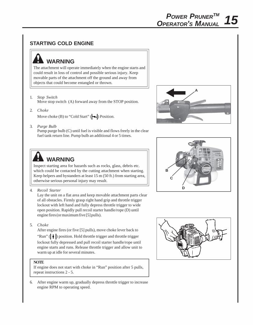
STARTING COLD ENGINE
WARNINGThe attachment will operate immediately when the engine starts andcould result in loss of control and possible serious injury. Keepmovable parts of the attachment off the ground and away fromobjects that could become entangled or thrown.
1. Stop SwitchMove stop switch (A) forward away from the STOP position.
2. Choke
Move choke (B) to “Cold Start” ( ) Position.
3. Purge BulbPump purge bulb (C) until fuel is visible and flows freely in the clearfuel tank return line. Pump bulb an additional 4 or 5 times.
WARNINGInspect starting area for hazards such as rocks, glass, debris etc.which could be contacted by the cutting attachment when starting.Keep helpers and bystanders at least 15 m (50 ft.) from starting area,otherwise serious personal injury may result.
4. Recoil StarterLay the unit on a flat area and keep movable attachment parts clearof all obstacles. Firmly grasp right hand grip and throttle triggerlockout with left hand and fully depress throttle trigger to wideopen position. Rapidly pull recoil starter handle/rope (D) untilengine fires (or maximum five [5] pulls).
5. ChokeAfter engine fires (or five [5] pulls), move choke lever back to
“Run” ( ) position. Hold throttle trigger and throttle trigger
lockout fully depressed and pull recoil starter handle/rope untilengine starts and runs. Release throttle trigger and allow unit towarm up at idle for several minutes.
NOTEIf engine does not start with choke in “Run” position after 5 pulls,repeat instructions 2 - 5.
6. After engine warm up, gradually depress throttle trigger to increaseengine RPM to operating speed.
B
D
16
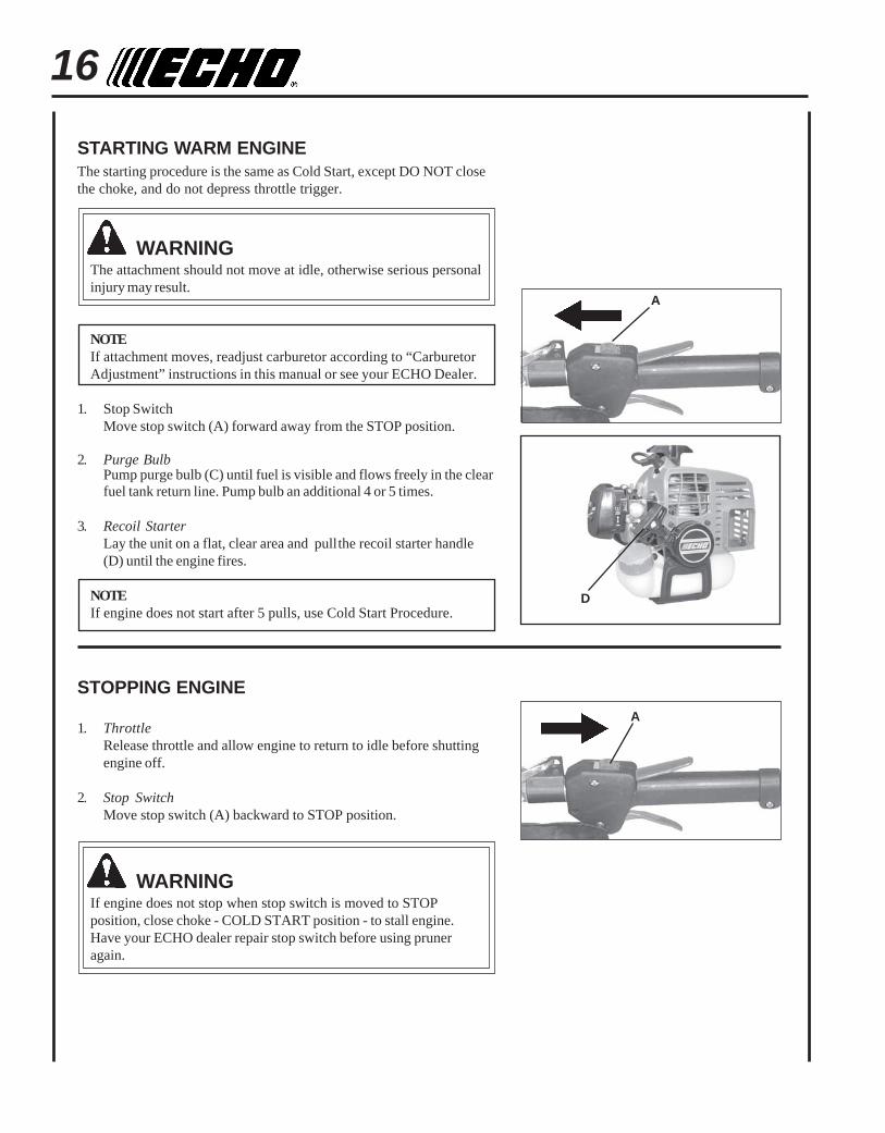
STARTING WARM ENGINEThe starting procedure is the same as Cold Start, except DO NOT closethe choke, and do not depress throttle trigger.
WARNINGThe attachment should not move at idle, otherwise serious personalinjury may result.
NOTEIf attachment moves, readjust carburetor according to “CarburetorAdjustment” instructions in this manual or see your ECHO Dealer.
1. Stop SwitchMove stop switch (A) forward away from the STOP position.
2. Purge BulbPump purge bulb (C) until fuel is visible and flows freely in the clearfuel tank return line. Pump bulb an additional 4 or 5 times.
3. Recoil StarterLay the unit on a flat, clear area and pullthe recoil starter handle(D) until the engine fires.
NOTEIf engine does not start after 5 pulls, use Cold Start Procedure.
STOPPING ENGINE
1. ThrottleRelease throttle and allow engine to return to idle before shuttingengine off.
2. Stop SwitchMove stop switch (A) backward to STOP position.
WARNINGIf engine does not stop when stop switch is moved to STOPposition, close choke - COLD START position - to stall engine.Have your ECHO dealer repair stop switch before using pruneragain.
A
A
D

POWER PRUNERTM
OPERATOR'S MANUAL 17
BLADE HITS REAR BRANCH
NOTCORRECT
PRUNING TECHNIQUES
The Power PrunerTM is designed for light to medium trimming of limbsand branches up to 203mm (8 in.) in diameter. Follow these tips forsuccessful operation.
• Plan cut carefully. Check direction branch will fall.
• Plan retreat path from falling branch. Cut branches bounce whenstriking ground.
• Long branches should be removed in several pieces.
• Do not stand directly beneath branch being cut.
• When ready to cut:Hold "cutting shoe" against branch. This will prevent whipping of thebranch. DO NOT use back and forth sawing action.
• Look out for branch immediately behind the branch being cut. If sawchain hits rear branch damage to saw chain and guide bar may occur.
• Accelerate to full throttle.
• Apply cutting pressure.
• Ease cutting pressure when nearing end of cut to maintain control.
• When pruning a limb 102 mm (4 in.) diameter or larger cut as follows:1. Under cut 1/4 limb diameter near tree trunk.2. Finish top cut slightly farther out on limb.3. Flush cut stub at trunk.
• DO NOT use for felling or bucking.
MAINTENANCEYour ECHO Power PrunerTM is designed to provide many hours of trouble free service. Regular scheduled maintenancewill help your pruner achieve that goal. If you are unsure or are not equipped with the necessary tools, you may want totake your unit to an ECHO Service Dealer for maintenance. To help you decide whether you want to DO-IT-YOURSELFor have the ECHO Dealer do it, each maintenance task has been graded. If the task is not listed, see your ECHO ServiceDealer for repairs.
SKILL LEVELS
Level 1 = Easy to do. Most required tools come with unit.Level 2 = Moderate difficulty. Some specialized tools may be required.Level 3 = Experience required. Specialized tools are required.
ECHO offers REPOWERTM Maintenance Kits and Parts to make your maintenance job easier. Just below each taskheading are listed the various part numbers required for that task. See your ECHO dealer for these parts.
NOTCORRECT
CORRECT
GUIDE AGAINSTBRANCH
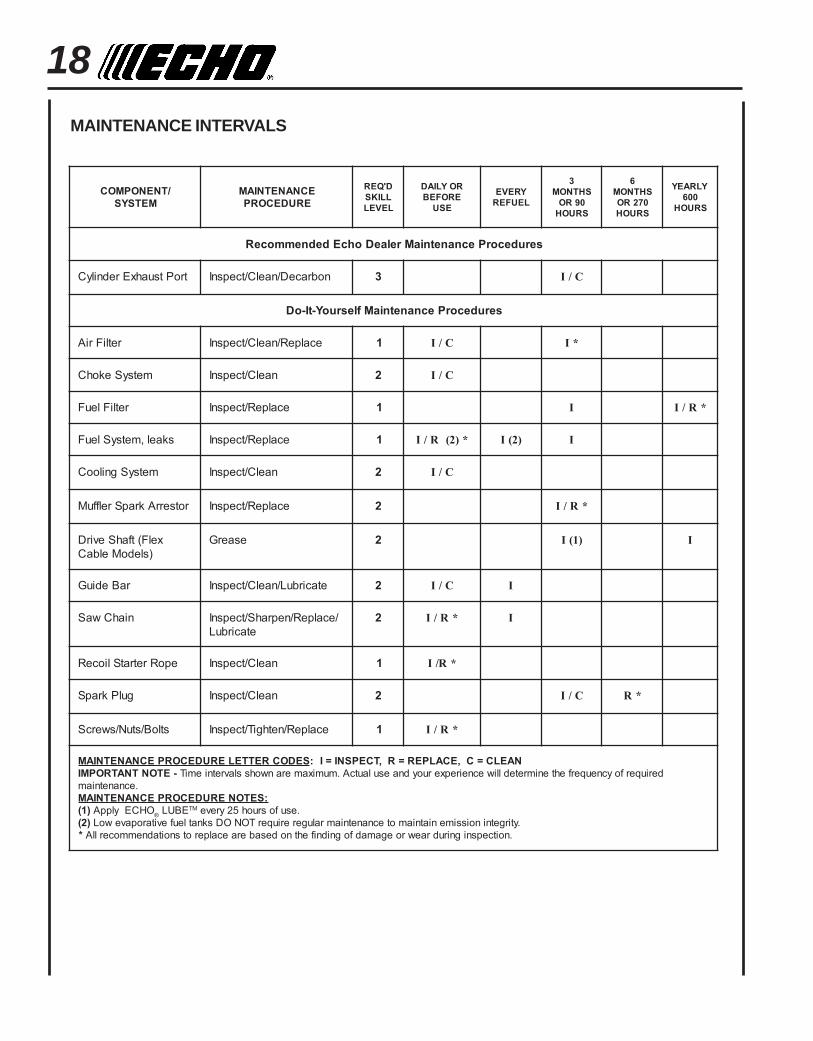
18MAINTENANCE INTERVALS
/TNENOPMOCMETSYS
ECNANETNIAMERUDECORP
D'QERLLIKSLEVEL
ROYLIADEROFEB
ESU
YREVELEUFER
3SHTNOM09ROSRUOH
6SHTNOM072ROSRUOH
YLRAEY006SRUOH
serudecorPecnanetniaMrelaeDohcEdednemmoceR
troPtsuahxErednilyC nobraceD/naelC/tcepsnI 3 C/I
serudecorPecnanetniaMflesruoY-tI-oD
retliFriA ecalpeR/naelC/tcepsnI 1 C/I *I
metsySekohC naelC/tcepsnI 2 C/I
retliFleuF ecalpeR/tcepsnI 1 I *R/I
skael,metsySleuF ecalpeR/tcepsnI 1 *)2(R/I )2(I I
metsySgnilooC naelC/tcepsnI 2 C/I
rotserrAkrapSrelffuM ecalpeR/tcepsnI 2 *R/I
xelF(tfahSevirD)sledoMelbaC
esaerG 2 )1(I I
raBediuG etacirbuL/naelC/tcepsnI 2 C/I I
niahCwaS /ecalpeR/neprahS/tcepsnIetacirbuL
2 *R/I I
epoRretratSlioceR naelC/tcepsnI 1 *R/I
gulPkrapS naelC/tcepsnI 2 C/I *R
stloB/stuN/swercS ecalpeR/nethgiT/tcepsnI 1 *R/I
SEDOCRETTELERUDECORPECNANETNIAM NAELC=C,ECALPER=R,TCEPSNI=I:-ETONTNATROPMI deriuqerfoycneuqerfehtenimretedlliwecneirepxeruoydnaesulautcA.mumixameranwohsslavretniemiT
.ecnanetniam:SETONERUDECORPECNANETNIAM
)1( OHCEylppA ® EBUL MT .esufosruoh52yreve)2( .ytirgetninoissimeniatniamotecnanetniamralugereriuqerTONODsknatleufevitaropavewoL
* .noitcepsnignirudraewroegamadfognidnifehtnodesaberaecalperotsnoitadnemmocerllA
POWER PRUNERTM
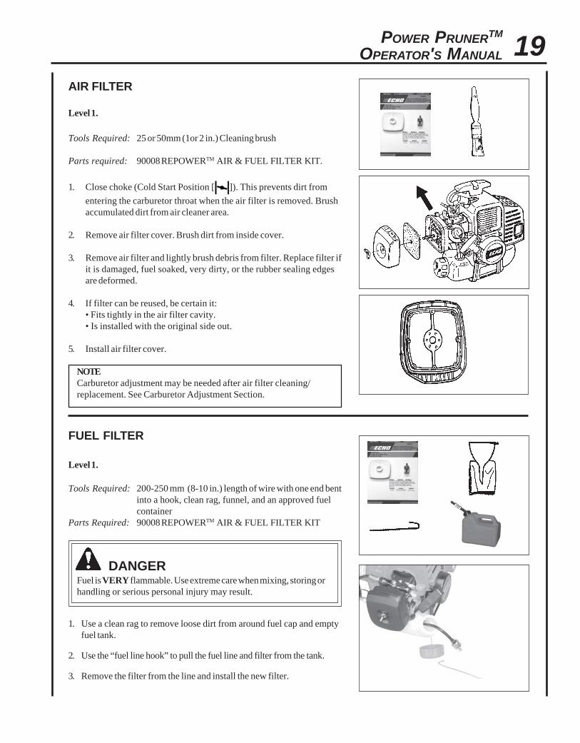
OPERATOR'S MANUAL 19AIR FILTER
Level 1.
Tools Required: 25 or 50mm (1or 2 in.) Cleaning brush
Parts required: 90008 REPOWERTM AIR & FUEL FILTER KIT.
1. Close choke (Cold Start Position [ ]). This prevents dirt from
entering the carburetor throat when the air filter is removed. Brushaccumulated dirt from air cleaner area.
2. Remove air filter cover. Brush dirt from inside cover.
3. Remove air filter and lightly brush debris from filter. Replace filter ifit is damaged, fuel soaked, very dirty, or the rubber sealing edgesare deformed.
4. If filter can be reused, be certain it:• Fits tightly in the air filter cavity.• Is installed with the original side out.
5. Install air filter cover.
NOTECarburetor adjustment may be needed after air filter cleaning/replacement. See Carburetor Adjustment Section.
FUEL FILTER
Level 1.
Tools Required: 200-250 mm (8-10 in.) length of wire with one end bentinto a hook, clean rag, funnel, and an approved fuelcontainer
Parts Required: 90008 REPOWERTM AIR & FUEL FILTER KIT
DANGERFuel is VERY flammable. Use extreme care when mixing, storing orhandling or serious personal injury may result.
1. Use a clean rag to remove loose dirt from around fuel cap and emptyfuel tank.
2. Use the “fuel line hook” to pull the fuel line and filter from the tank.
3. Remove the filter from the line and install the new filter.

20SPARK PLUG
Level 2.
Tools Required: 10x19mm (13/32x3/4) T-Wrench, feeler gauge,soft metal brush
Parts Required: REPOWERTM Tune-Up Kit P/N 90074
IMPORTANTUse only NGK BPM-8Y spark plug (BPMR-8Y in Canada)otherwise severe engine damage may occur.
1. Remove spark plug and check for fouling, worn and rounded centerelectrode.
2. Clean the plug or replace with a new one. DO NOT sand blast toclean. Remaining sand will damage engine.
3. Adjust spark plug gap 0.65mm (0.026 in.) by bending outer electrode.
4. Tighten spark plug to 150-170 kg/cm (130-150 in. lb.).
COOLING SYSTEM CLEANING
Level 2.
Tools Required: Screwdriver, 3 mm Hex wrench, 25 or 50mm(1or 2 in.) cleaning brush
Parts Required: None.
IMPORTANTTo maintain proper engine operating temperatures, cooling air mustpass freely through the cylinder fin area. This flow of air carriescombustion heat away from the engine.
Overheating and engine seizure can occur when:
• Air intakes are blocked, preventing cooling air from reaching thecylinder.
• Dust and grass build up on the outside of the cylinder. This buildup insulates the engine and prevents the heat from leaving.
Removal of cooling passage blockages or cleaning of cooling fins isconsidered “Normal Maintenance.” Any failure attributed to lack ofmaintenance is not warranted.
0.65 mm(0.026 in.)
POWER PRUNERTM
OPERATOR'S MANUAL 21
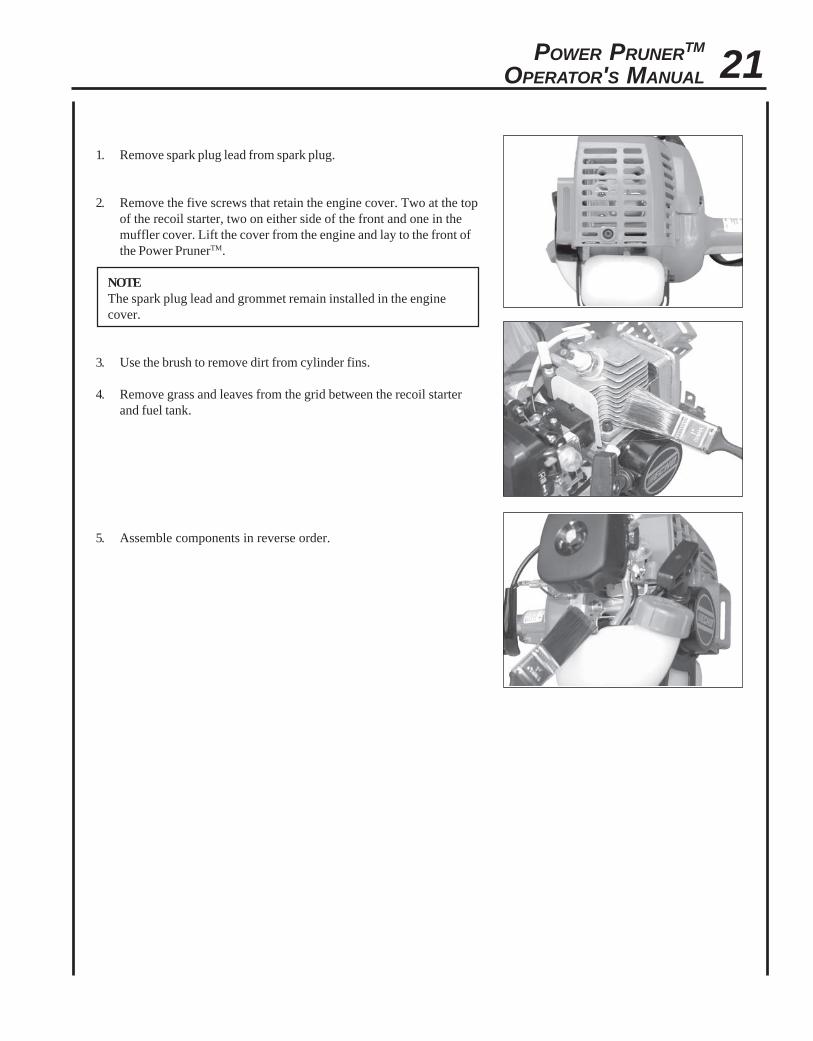
1. Remove spark plug lead from spark plug.
2. Remove the five screws that retain the engine cover. Two at the topof the recoil starter, two on either side of the front and one in themuffler cover. Lift the cover from the engine and lay to the front ofthe Power PrunerTM.
NOTEThe spark plug lead and grommet remain installed in the enginecover.
3. Use the brush to remove dirt from cylinder fins.
4. Remove grass and leaves from the grid between the recoil starterand fuel tank.
5. Assemble components in reverse order.

22
A
B
C
EXHAUST SYSTEM
Spark Arrestor Screen
Level 2.
Tools Required: Screwdriver, Soft metal brush, 3 mm hex wrench
Parts Required: Spark Arrestor Screen, Gasket
1. Remove spark plug lead from spark plug.
2. Remove engine cover. See “Cleaning Cooling System” pages20 & 21 for step by step instructions.
3. Place piston at Top Dead Center (TDC) to prevent carbon/dirtfrom entering cylinder.
4. Remove spark arrestor screen cover (A), gasket (B), and screen (C)from muffler body.
5. Clean carbon deposits from muffler components.
NOTEWhen cleaning carbon deposit, be careful not to damage thecatalytic element inside muffler.
6. Replace screen if it is cracked, plugged or has holes burnedthrough.
7. Assemble components in reverse order.
NOTEWhen installing the engine cover, be certain the tabs of the metaldeflector shield are in the slot of the engine cover.
Cylinder Exhaust Port
Level 3.
IMPORTANTThe cylinder exhaust port must be inspected and cleaned of excesscarbon every 3 months or 90 hours of operation in order to maintainthis engine within the emissions durability period. ECHO stronglyrecommends that you return your unit to your ECHO dealer for thisimportant maintenance service.
POWER PRUNERTM
OPERATOR'S MANUAL 23CARBURETOR ADJUSTMENT
Engine Break-InNew engines must be operated a minimum duration of two tanks of fuelbreak-in before carburetor adjustments can be made. During the break-inperiod your engine performance will increase and exhaust emissions willstabilize. Idle speed can be adjusted as required.
High Altitude AdjustmentThis engine has been factory adjusted to maintain satisfactory starting,emission, and durability performance up to 1,000 feet above mean sealevel (MSL). To maintain proper engine operation above 1,000 feet MSLthe carburetor must be adjusted by an authorized ECHO service dealer.
IMPORTANTIf the engine is adjusted for operation above 1,000 feet MSL, thecarburetor must be re-adjusted when operating the engine below1,000 feet MSL, otherwise severe engine damage can result.
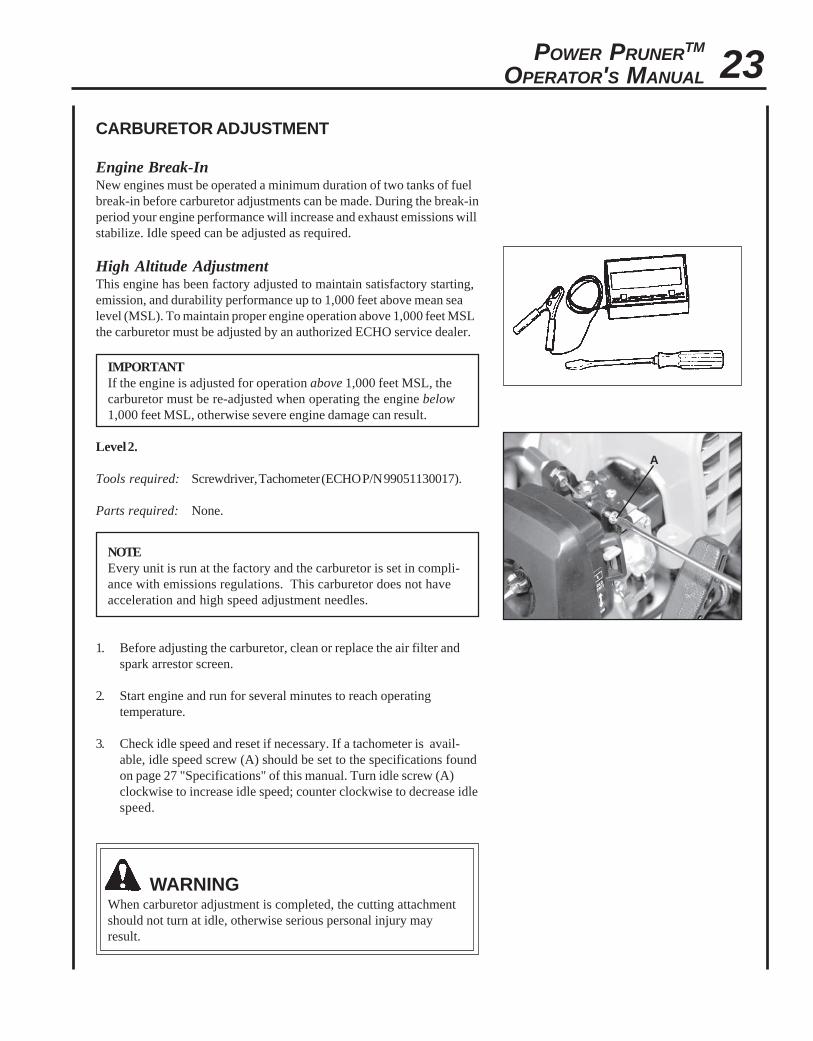
Level 2.
Tools required: Screwdriver, Tachometer (ECHO P/N 99051130017).
Parts required: None.
NOTEEvery unit is run at the factory and the carburetor is set in compli-ance with emissions regulations. This carburetor does not haveacceleration and high speed adjustment needles.
1. Before adjusting the carburetor, clean or replace the air filter andspark arrestor screen.
2. Start engine and run for several minutes to reach operatingtemperature.
3. Check idle speed and reset if necessary. If a tachometer is avail-able, idle speed screw (A) should be set to the specifications foundon page 27 "Specifications" of this manual. Turn idle screw (A)clockwise to increase idle speed; counter clockwise to decrease idlespeed.
WARNINGWhen carburetor adjustment is completed, the cutting attachmentshould not turn at idle, otherwise serious personal injury mayresult.
A

24
GUIDE BAR AND SAW CHAIN REPLACEMENT
WARNINGNever try to replace or adjust guide bar and saw chain with engine running. This saw chain is VERY sharp, wearheavy gloves to protect your hands when handling it. Wear eye protection meeting CE or ANSI specification Z87.1.
B
A
C A B
D B
Guide Bar Replacement / InstallationLevel 2
Tools Required: 10 x 19 mm (13/32 x 3/4 in.) T-wrench
1. Remove two (2) 6 mm guide bar nuts (A), and turn saw chaintension adjustment slot (B) counterclockwise to release tension.
2. Remove sprocket cover (C).
3. Remove guide bar and saw chain from gear case and sprocket.
4. Remove chain from guide bar and check guide bar for damage andexcessive or uneven wear. Replace guide bar if necessary.
5. Turn saw chain tension adjuster slot (B) counterclockwise until itstops.
6. Install chain on guide bar with cutters on top of bar facing towardbar tip.
7. Install guide bar and chain on gear case, engaging chain with drivesprocket (D).
8. Turn tension adjustment slot clockwise to take up slack in sawchain.
9. Install sprocket guard (C), and tighten guide bar nuts finger tight.
10. Adjust chain tension.
POWER PRUNERTM
OPERATOR'S MANUAL 25
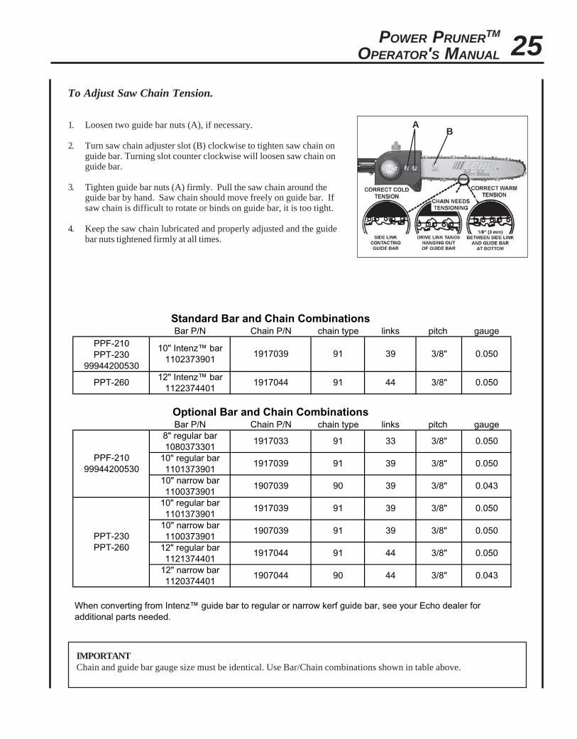
IMPORTANTChain and guide bar gauge size must be identical. Use Bar/Chain combinations shown in table above.
Standard Bar and Chain CombinationsBar P/N Chain P/N chain type links pitch gauge
PPF-210 PPT-230
99944200530
10" Intenz™ bar 1102373901
1917039 91 39 3/8" 0.050
PPT-26012" Intenz™ bar
11223744011917044 91 44 3/8" 0.050
Optional Bar and Chain CombinationsBar P/N Chain P/N chain type links pitch gauge
PPF-210 99944200530
8" regular bar 1080373301
1917033 91 33 3/8" 0.050
10" regular bar 1101373901
1917039 91 39 3/8" 0.050
10" narrow bar 1100373901
1907039 90 39 3/8" 0.043
PPT-230 PPT-260
10" regular bar 1101373901
1917039 91 39 3/8" 0.050
10" narrow bar 1100373901
1907039 91 39 3/8" 0.050
12" regular bar 1121374401
1917044 91 44 3/8" 0.050
12" narrow bar 1120374401
1907044 90 44 3/8" 0.043
When converting from Intenz™ guide bar to regular or narrow kerf guide bar, see your Echo dealer for additional parts needed.
To Adjust Saw Chain Tension.
1. Loosen two guide bar nuts (A), if necessary.
2. Turn saw chain adjuster slot (B) clockwise to tighten saw chain onguide bar. Turning slot counter clockwise will loosen saw chain onguide bar.
3. Tighten guide bar nuts (A) firmly. Pull the saw chain around theguide bar by hand. Saw chain should move freely on guide bar. Ifsaw chain is difficult to rotate or binds on guide bar, it is too tight.
4. Keep the saw chain lubricated and properly adjusted and the guidebar nuts tightened firmly at all times.
AB

26
FILING SAW CHAIN
Level 3.
Tools required: 4 mm (5/32 in.) Round File, Flat File, Depth Gauge
IMPORTANTDull or damaged cutters will result in poor cutting performance,increased vibration, and premature saw chain failure.
WARNINGAlways stop engine and disconnect spark plug wire beforeservicing guide bar and saw chain. Always wear gloves when filingsaw chain, otherwise serious personal injury may result.
1. Set round file (A) in cutter at 30° angle. One fifth (1/5) of the fileshould be exposed above top cutter edge.
2. Keep file horizontal in cutter and file in one direction.
3. File until cutter top and side bevel edges are sharp without nicks.
4. Place depth gauge tool (B) firmly on top of cutter with .025 in. slotand end against front cutter raker. File cutter raker with flat fileuntil flush with top of depth gauge.
5. Finish cutter sharpening by rounding front raker edge (C) with flatfile.
6. Properly filed cutter is as shown.
7. Apply clean oil and rotate saw chain slowly to wash away filings.
8. If saw chain is coated or clogged with resin, clean in kerosene, thensoak in oil.
1
2
3
4
5
30°
90°
(TOP PLATE ANGLE)
(DEPTH GAUGE)
(TOP PLATE CUTTING ANGLE)
6

POWER PRUNERTM
OPERATOR'S MANUAL 27TROUBLESHOOTING
TRAHCGNITOOHSELBUORTMELBORPENIGNE
melborP kcehC sutatS esuaC ydemeR
enignE-sknarc/drahstrats
t'nseodtrats
roterubractaleuF taleufoNroterubrac
deggolcreniartsleuFdeggolcenilleuF
roterubraC
ecalperronaelCecalperronaelC
relaedohcEruoyeeS
rednilyctaleuF
rednilyctaleufoN roterubraC relaedohcEruoyeeS
leufhtiwtewrelffuM hcirooterutxiMleuF
ekohcnepOretlifriaecalper/naelC
roterubractsujdArelaedohcEruoyeeS
dnetakrapSeriwgulpfo krapsoN
ffohctiwspotSmelborplacirtcelE
hctiwskcolretnI
NOothctiwsnruTrelaedohcEruoyeeSrelaedohcEruoyeeS
gulptakrapS krapsoN
tcerrocnipagkrapSnobrachtiwderevoC
leufhtiwdeluoFevitcefedgulP
).ni620.0(mm56.ottsujdAecalperronaelCecalperronaelC
gulpecalpeR
enignE,snurroseidtubtonseodetareleccaylreporp
retlifriA ytridretlifriA raewlamroN ecalperronaelC
retlifleuF ytridretlifleuF seudiser/stnanimatnoCleufni ecalpeR
tnevleuF deggulptnevleuF seudiser/stnanimatnoCleufni ecalperronaelC
gulPkrapS nrow/ytridgulP raewlamroN ecalperrotsujdadnanaelC
roterubraC reporpmItnemtsujda noitarbiV tsujdA
metsySgnilooC evissecxEsirbed/trid
ninoitarepodednetxEsnoitacolytsud/ytrid naelC
rotserrAkrapSneercS
,dekcarcneercSro,deggulpdetarofrep
raewlamroN ecalpeR
enignEd seo n toc knar
A/N A/N melborpenignelanretnI relaedohcEruoyeeS
WARNINGFuel vapors are extremely flammable and may cause fire and/or explosion. Never test for ignition spark bygrounding spark plug near cylinder plug hole, otherwise serious personal injury may result.
28
2. Place the stop switch in the "OFF" position.
3. Remove accumulation of grease, oil, dirt and debrisfrom exterior of unit.
IMPORTANTSome tree sap and resins are corrosive. Thoroughlywash the guide bar and sprocket areas after each use,then coat metal parts with light oil.
4. Perform all periodic lubrication and services that arerequired.
5. Tighten all the screws and nuts.
6. Drain the fuel tank completely and pull the recoilstarter handle several times to remove fuel from thecarburetor.
STORAGE
Long Term Storage (over 30 days)
WARNINGDuring operation the muffler or catalytic muffler and surrounding cover become hot. Always keep exhaust area clearof flammable debris during transportation or when storing, otherwise serious property damage or personal injury mayresult.
Do not store your unit for a prolonged period of time (30 days or longer) without performing protective storage mainte-nance which includes the following:
1. Store unit in a dry, dust free place, out of the reach of children.
WARNINGDo not store in enclosure where fuel fumes may accumulate or reach an open flame or spark or serious personalinjury may result.
7. Remove the spark plug and pour 7 cc (1/4 oz.) offresh, clean, two-stroke engine oil into the cylinderthrough the spark plug hole.
A. Place a clean cloth over the spark plug hole.B. Pull the recoil starter handle 2-3 times to
distribute the oil inside the engine.C. Observe the piston location through the spark
plug hole. Pull the recoil starter handle slowlyuntil the piston reaches the top of its travel andleave it there.
8. Install the spark plug (do not connect spark plugcable).
9. Install the guide bar cover on the guide bar and sawchain during storage.

POWER PRUNERTM
OPERATOR'S MANUAL 29
SPECIFICATIONS
MODEL ---------------------------------------------------- PPF-210
Length ------------------------------------------------------- 2.38 m (7 ft, 9.7 in.)
Length w/Optional 3 ft. extension ------------------------ 3.29 m (10 ft, 9.7 in.)
Width -------------------------------------------------------- 0.23 m (9.06 in.)
Height ------------------------------------------------------- 0.22 m (8.7 in.)
Weight (dry) ------------------------------------------------ 6.0 kg (13.3 lb.)
Engine Type ------------------------------------------------ Air cooled, two-stroke, single cylinder gasoline engine
Bore ---------------------------------------------------------- 32.2 mm (1.27 in.)
Stroke -------------------------------------------------------- 26.0 mm (1.02 in.)
Displacement ----------------------------------------------- 21.2 cc (1.29 cu. in.)
Exhaust System -------------------------------------------- Spark Arrestor Muffler w/catalyst
Carburetor -------------------------------------------------- Zama w/primer bulb
Ignition System -------------------------------------------- CDI (capacitor discharge ignition)
Spark Plug -------------------------------------------------- NGK BPM-8Y Gap 0.65 mm (0.026 in.)
Fuel ---------------------------------------------------------- Mixed (Gasoline and Two-stroke Oil)
Fuel/Oil Ratio ----------------------------------------------- 50:1 two-stroke air cooled engine oil
Gasoline ----------------------------------------------------- 89 Octane unleaded. DO NOT use fuel containing methyl alcohol,
more than 10% ethyl alcohol or 15% MTBE.
Oil ------------------------------------------------------------ Power Blend TM Premium Universal 2-Stroke Oil
Fuel Tank Capacity ---------------------------------------- 0.45 lit. (15.2 US fl. oz.)
Recoil Starter System -------------------------------------- Automatic Recoil Starter
Clutch ------------------------------------------------------- Centrifugal Type
Sprocket Type ---------------------------------------------- 6 tooth spur, 9.53 mm (3/8 inch) pitch
Shaft Tube Assembly ------------------------------------- 25.4 mm (1 in.) Galvanized Steel
Power Transmission Shaft -------------------------------- 6.35 mm (1/4 inch) Flex Cable
Gear Case Ratio -------------------------------------------- 3:1
Oiling System ----------------------------------------------- Automatic
Chain Oil Capacity ----------------------------------------- 225 ml (7.6 oz.)
Handles ----------------------------------------------------- Right hand grip w/throttle trigger and throttle trigger lockout / Left
foam hand grip
Shoulder Harness ------------------------------------------ Standard
Idle Speed (RPM) ------------------------------------------ 2,750 - 3,250
Clutch Engagement Speed (RPM) ----------------------- 3,600 - 4,200
Wide Open Throttle Speed (RPM) ----------------------- 9,500 - 11,500
Guide Bar and Saw Chain (91) ---------------------------- 254 mm (10 in.); 9.53 mm (3/8 inch) pitch chain, 0.050 gauge

30
NOTES

POWER PRUNERTM
OPERATOR'S MANUAL 31
NOTES

CONSUMER PRODUCTSUPPORT
1-800-673-15588:30 - 4:30 Mon - Fri C.S.T.
ECHO, INCORPORATED400 OAKWOOD ROAD
LAKE ZURICH, IL 60047
www.echo-usa.com
ADDITIONAL OR REPLACEMENT MANUALSSafety Manuals in English/Spanish or English/French are available, free of charge, from your ECHO dealer or atwww.echo-usa.com.Operator's and Parts Manuals are available by:• Downloading free from www.echo-usa.com• Purchasing from your Echo Dealer.• Manuals are available by sending a written request stating the model number and serial number of your Echo unit, part
number of the manual, your name and address, and mail to the address below.Safety Videos are available from your Echo dealer. A $5.00 shipping charge will be required for each video.
DEALER?Call
1-800-432-ECHO1-800-432-3246
orwww.echo-usa.com
11001001/1199999912001001/12999999
SERVICING INFORMATION
PARTS/SERIAL NUMBERGenuine ECHO Parts and ECHO REPOWER™ Parts and Assemblies foryour ECHO products are available only from an Authorized ECHODealer. When you do need to buy parts always have the ModelNumber, Type and Serial Number of the unit with you. You can findthese numbers on the engine housing. For future reference, write themin the space provided below.
Model No. _____________ Type _________SN. ______________
SERVICEService of this product during the warranty period must be performedby an Authorized ECHO Service Dealer. For the name and address ofthe Authorized ECHO Service Dealer nearest you, ask your retailer orcall: 1-800-432-ECHO (3246). Dealer information is also available on ourWeb Site. When presenting your unit for Warranty service/repairs,proof of purchase is required.
ECHO CONSUMER PRODUCT SUPPORTIf you require assistance or have questions concerning the application,operation or maintenance of this product you may call the ECHOConsumer Product Support Department at 1-800-673-1558 from 8:30 amto 4:30 pm (Central Standard Time) Monday through Friday. Beforecalling, please know the model and serial number of your unit to helpyour Consumer Product Support Representative.
WARRANTY REGISTRATIONTo ensure trouble free warranty coverage it is important that youregister your ECHO equipment on-line at www.echo-usa.com. Otherregistration options are by automated phone at 1-800-432-3246 or byfilling out the warranty registration card supplied with your unit.Registering your product confirms your warranty coverage andprovides a direct link between you and ECHO if we find it necessary tocontact you.