operator´s manual internal vibrator with integrated inverter
TRANSCRIPT
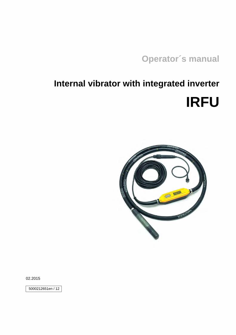
Operator´s manual
Internal vibrator with integrated inverter
IRFU
02.2015
5000212651en / 12
Manufacturer
Wacker Neuson Produktion GmbH & Co. KGPreußenstraße 4180809 Münchenwww.wackerneuson.com
Tel.: +49-(0)89-354 02-0Fax: +49-(0)89-354 02-390
Translation of the original operator's manual in German
5000212651IVZ.fm 3
1 Foreword .................................................................................................................... 5
2 Introduction ............................................................................................................... 62.1 Means of representation for this operator's manual ....................................................... 62.2 Wacker Neuson representative...................................................................................... 72.3 Described machine types............................................................................................... 72.4 Identification of the machine .......................................................................................... 8
3 Safety ......................................................................................................................... 93.1 Principle ......................................................................................................................... 93.2 Qualification of the operating personnel....................................................................... 123.3 Protective gear ............................................................................................................. 133.4 Transport...................................................................................................................... 133.5 Operating safety........................................................................................................... 143.6 Safety during the operation of hand machines............................................................. 153.7 Safety during the operation of electric appliances ....................................................... 163.8 Maintenance................................................................................................................. 17
4 Safety and information labels ................................................................................ 19
5 Scope of delivery .................................................................................................... 20
6 Structure and function ........................................................................................... 216.1 Application.................................................................................................................... 216.2 Functionality ................................................................................................................. 21
7 Components and operator's controls ................................................................... 23
8 Transport ................................................................................................................. 25
9 Use and operation ................................................................................................... 269.1 Prior to starting the machine ........................................................................................ 269.2 Starting up.................................................................................................................... 269.3 Decommissioning......................................................................................................... 309.4 Cleaning ....................................................................................................................... 31
10 Maintenance ............................................................................................................ 3210.1 Maintenance personnel qualifications .......................................................................... 3210.2 Maintenance schedule ................................................................................................. 3210.3 Maintenance work ........................................................................................................ 33
11 Malfunctions ............................................................................................................ 3511.1 Bodyguard®................................................................................................................................................ 35
11.2 Inverter ......................................................................................................................... 35
12 Disposal ................................................................................................................... 3712.1 Disposal of waste electrical and electronic equipment................................................. 37

4 5000212651IVZ.fm
13 Technical data ......................................................................................................... 3813.1 IRFU 30 ........................................................................................................................ 3813.2 IRFU 38 ........................................................................................................................ 4013.3 IRFU 45 ........................................................................................................................ 4413.4 IRFU 57 ........................................................................................................................ 4813.5 IRFU 65 ........................................................................................................................ 5213.6 Extension cable ............................................................................................................ 56
14 Glossary ................................................................................................................... 59
EC Declaration of Conformity ................................................................................ 61
1 Foreword
100_0000_0002.fm 5
1 Foreword
This operator's manual contains information and procedures for the safe opera-tion and maintenance of your Wacker Neuson machine. In the interest of your own safety and to prevent accidents, you should carefully read through the safety information, familiarize yourself with it and observe it at all times.
This operator's manual is not a manual for extensive maintenance and repair work. Such work should be carried out by Wacker Neuson service or authorized specialists.
The safety of the operator was one of the most important aspects taken into con-sideration when this machine was designed. Nevertheless, improper use or in-correct maintenance can pose a risk. Please operate and maintain your Wacker Neuson machine in accordance with the instructions in this operator's manual. Your reward will be troublefree operation and a high degree of availability.
Defective machine parts must be replaced immediately!
Please contact your Wacker Neuson representative if you have any questions concerning operation or maintenance.
All rights reserved, especially reproduction and distribution rights.
Copyright 2015 Wacker Neuson Produktion GmbH & Co. KG
No part of this publication may be reproduced in any form or by any means, elec-tronic or mechanical, including photocopying, without the expressed written per-mission of Wacker Neuson.
Any type of reproduction, distribution or storage on data media of any type and form not authorized by Wacker Neuson represents an infringement of copyright and will be prosecuted.
We expressly reserve the right to make technical modifications – even without special notice – which aim at further improving our machines or their safety stan-dards.
2 Introduction
6 100_0000_0003.fm
2 Introduction
2.1 Means of representation for this operator's manual
Warning symbols
This operator's manual contains safety information of the categories: DANGER, WARNING, CAUTION, NOTICE.
They should be followed to prevent danger to life and limb of the operator or dam-age to equipment and exclude improper service.
Notes
Note: Complementary information will be displayed here.
DANGERThis warning notice indicates immediate hazards that result in serious injury or even death. Danger can be avoided by the following the actions mentioned.
WARNINGThis warning notice indicates possible hazards that can result in serious injury or even death. Danger can be avoided by the following the actions mentioned.
CAUTIONThis warning notice indicates possible hazards that can result in minor injury. Danger can be avoided by the following the actions mentioned.
NOTICEThis warning notice indicates possible hazards that can result in material dam-age. Danger can be avoided by the following the actions mentioned.
2 Introduction
100_0000_0003.fm 7
Instructions
This symbol indicates there is something for you to do.
1. Numbered instructions indicate that you have to carry out something in a de-fined sequence.
This symbol is used for lists.
2.2 Wacker Neuson representative
Depending on your country, your Wacker Neuson representative is your Wacker Neuson service, your Wacker Neuson affiliate or your Wacker Neuson dealer.
You can find the addresses in the Internet at www.wackerneuson.com.
The address of the manufacturer is located at the beginning of this operator's manual.
2.3 Described machine types
This operator's manual is valid for different machine types from a product range. Therefore some figures can differ from the actual appearance of your machine. It is also possible that the descriptions include components which are not a part of your machine.
Details for the described machine types can be found in the chapter Technical data.

2 Introduction
8 100_0000_0003.fm
2.4 Identification of the machine
Nameplate data
The nameplate lists information that uniquely identifies your machine. This infor-mation is needed to order spare parts and when requesting additional technical information.
Enter the information of your machine into the following table:
Item Designation Your information
1 Group and type
2 Construction year
3 Machine no.
4 Version no.
5 Item no.
3 Safety
100_0101_si_0001.fm 9
3 Safety
3.1 Principle
State of the art
This machine has been constructed with state-of-the-art technology according to the recognized rules of safety. Nevertheless, when used improperly, dangers to the life and limb of the operator or to third persons or damage to the machine or other materials cannot be excluded.
Proper use
The machine may only be used for compacting fresh concrete. The vibrator head has to be immersed in the fresh concrete.
The vibrator head may not be immersed into acidic or alkaline liquids.
The vibrator head may not come into contact with or be inserted into parts of the body.
Its proper use also includes the observance of all instructions contained in this operator's manual as well as complying with the required service and mainte-nance instructions.
Any other use is regarded as improper. Any damage resulting from improper use will void the warranty and the liability on behalf of the manufacturer. The operator assumes full responsibility.
Structural modifications
Never attempt to modify the machine without the written permission of the man-ufacturer. To do so will endanger your safety and the safety of other people! In addition, this will void the warranty and the liability on behalf of the manufacturer.
Especially the following are cases of structural modifications:
Opening the machine and the permanent removal of components from Wacker Neuson.
Installing new components which are not from Wacker Neuson and not equiv-alent to the original parts in design and quality.
Installation of accessories which are not from Wacker Neuson.
It is no problem to install spare parts from Wacker Neuson.
It is no problem to install accessories that are available in the Wacker Neuson product range of your machine. Please refer to the installation regulations in this operator's manual.
Do not drill into the housing, e.g. to install signs. Water could penetrate the hous-ing and damage the machine.
3 Safety
10 100_0101_si_0001.fm
Requirements for operation
The ability to operate the machine safely requires:
Proper transport, storage and setup. Careful operation. Careful service and maintenance.
Operation
Operate the machine only as intended and only when in proper working condi-tion.
Operate the machine in a safety-conscious manner with all safety devices at-tached and enabled. Do not modify or disable any safety devices.
Before starting operation, check that all control and safety devices are function-ing properly.
Never operate the machine in a potentially explosive environment.
Supervision
Never leave the machine running unattended!
Maintenance
Regular maintenance work is required in order for the machine to operate prop-erly and reliably over time. Failure to perform adequate maintenance reduces the safety of the machine.
Strictly observe the prescribed maintenance intervals. Do not use the machine if it requires maintenance or repairs.
Malfunctions
If you detect a malfunction, you must shut down and secure the machine imme-diately.
Eliminate the malfunctions that impair safety immediately!
Have damaged or defective components replaced immediately!
For further information, refer to chapter Troubleshooting.
Spare parts, accessories
Use only spare parts from Wacker Neuson or such that are equivalent to the orig-inal parts in design and quality.
Only use accessories from Wacker Neuson.
Non-compliance will exempt the manufacturer from all liability.
3 Safety
100_0101_si_0001.fm 11
Exclusion of liability
Wacker Neuson will refuse to accept liability for injuries to persons or for damage to materials in the following cases:
Structural modifications. Improper use. Failure to comply with this operator's manual. Improper handling. Using of spare parts which are not from Wacker Neuson and not equivalent
to the original parts in design and quality. Using of accessories which are not from Wacker Neuson.
Operator's manual
Always keep the operator's manual near the machine or near the worksite for quick reference.
If you have misplaced the operator's manual or require an additional copy, con-tact your Wacker Neuson representative or download the operator's manual from the Internet (www.wackerneuson.com).
Always hand over this operator's manual to other operators or to the future owner of the machine.
Country-specific regulations
Observe the country-specific regulations, standards and guidelines in reference to accident prevention and environmental safety, for example those pertaining to hazardous materials and wearing protective gear.
Complement the operator's manual with additional instructions taking into ac-count the operational, regulatory, national or generally applicable safety guide-lines.
Operator's controls
Always keep the operator's controls of the machine dry, clean and free of oil or grease.
Operating elements such as ON/OFF switch, gas handles etc. may not be locked, manipulated or changed without authorization.
Checking for signs of damage
Inspect the machine when it is switched off for any signs of damage at least once per work shift.
Do not operate the machine if there is visible damage or defects.
Have any damage or defects eliminated immediately.

3 Safety
12 100_0101_si_0001.fm
3.2 Qualification of the operating personnel
Operator qualifications
Only trained personnel are permitted to start and operate the machine. The fol-lowing rules also apply:
You are physically and mentally fit. You have received instruction on how to independently operate the machine. You have received instruction in the proper use of the machine. You are familiar with required safety devices. You are authorized to start machines and systems in accordance with the
standards governing safety. Your company or the operator has assigned you to work independently with
this machine.
Incorrect operation
Incorrect operation or misuse by untrained personnel can endanger the health and safety of the operator or third persons and also cause machine and material damage.
Operating company responsibilities
The operating company must make the operator's manual available to the oper-ator and ensure that the operator has read and understood it.
Work recommendations
Please observe the recommendations below:
Work only if you are in a good physical condition. Work attentively, particularly as you finish. Do not operate the machine when you are tired. Carry out all work calmly, circumspectly and carefully. Never operate the machine under the influence of alcohol, drugs or medica-
tion. This can impair your vision, reactions and your judgment. Work in a manner that does not endanger others. Ensure that no persons or animals are within the danger zone.
3 Safety
100_0101_si_0001.fm 13
3.3 Protective gear
Work clothing
Clothing should be appropriate, i.e. should be close-fitting but not restrict your movement.
When on construction sites, do not wear long hair loosely, loose clothing or jew-elry including rings. These objects can easily get caught or be drawn in by mov-ing machine parts.
Only wear clothing made of material that is not easily flammable.
Personal protective gear
Wear personal protective gear to avoid injuries or health hazards:
Non-skid, hard-toed shoes. Work gloves made of durable material. Overalls made of durable material. Hard hat. Ear protection.
Ear protection
This machine generates noise that exceeds the country-specific permissible noise levels (individual rating level). It may therefore be necessary to wear ear protection. You can find the exact value in the chapter Technical Data.
When wearing ear protection while working, you must pay attention and exercise caution because your hearing is limited, e.g. in case someone screams or a sig-nal tone sounds.
Wacker Neuson recommends that you always wear ear protection.
3.4 Transport
Switching off the machine
Before you transport the machine, switch it off and pull the plug out of the plug receptacle. Allow the motor to cool down.
Transporting the machine
Secure the machine on the transport device against tilting, falling or slipping.
Lifting the machine
A falling machine can cause serious injuries.
The machine has no lifting or lashing points.
When lifting the machine, secure it in a closed transport container or similar in order to prevent it from toppling, falling or slipping away.
3 Safety
14 100_0101_si_0001.fm
Restarting
Machines, machine parts, accessories or tools that were detached for transport purposes must be re-mounted and fastened before restarting.
Only operate in accordance with the operating instructions.
3.5 Operating safety
Explosible environment
Never operate the machine in a potentially explosive environment.
Work environment
Familiarize yourself with your work environment before you start work. This in-cludes e.g. the following items:
Obstacles in the work and traffic area. Load-bearing capacity of the ground. The measures needed to cordon off the construction site from public traffic in
particular. The measures needed to secure walls and ceilings. Options available in the event of an accident.
Starting the machine
Observe the safety information and warning notices located on the machine and in the operator's manual.
Never attempt to start a machine that requires maintenance or repairs.
Start the machine as described in the operator's manual.
Avoid body contact with grounded components.
Vertical stability
Always make sure that you stand firmly when working with the machine. This ap-plies particularly when working on scaffoldings, ladders, uneven or slippery floors etc.
Caution with hot parts
Do not touch the hot vibrator head during or shortly after operation. The vibrator head can become very hot and can cause severe burns.
Caution with movable parts
Keep your hands, feet and loose clothing away from moving or rotating machine parts. Parts of your body being pulled in or crushed can cause serious injuries.
Do not use components of to machine for climbing on or holding onto
Never use the protective hose, power cable or other components of the machine for climbing on or holding onto.
3 Safety
100_0101_si_0001.fm 15
Switching off the machine
Switch off the machine and pull the plug out of the plug receptacle in the following situations:
Before breaks. If you are not using the machine.
Before storing the machine, wait until it has completely stopped running.
Store the machine or put it down in such a way that it cannot tilt, fall down or slip.
Storage
Set the machine down or store it securely so that it cannot tilt, fall down or slip.
Storage location
After operation, allow the machine to cool and then store it in a sealed-off, clean and dry location protected against frost and inaccessible to children.
Vibrations
When manually operated machines are intensively used, long-term damage caused by vibrations cannot be precluded.
Observe the relevant legal instructions and guidelines to minimize vibration stress.
Details on vibration stress associated with the machine can be found in the chap-ter Technical Data.
3.6 Safety during the operation of hand machines
Setting the hand machine down properly
Set the machine down carefully. Do not drop the machine to the floor or from greater heights. Dropping the machine can cause injuries to other persons or the machine itself can be damaged.
Safe working with hand machines
While working, always hold the machine on the handle provided.
3 Safety
16 100_0101_si_0001.fm
3.7 Safety during the operation of electric appliances
Specific regulations for electrical appliances
Observe the safety information provided in the brochure General Safety Rules which is included in the scope of delivery of your machine.
Also observe the country-specific regulations, standards and guidelines in refer-ence to accident prevention in connection with electrical equipment and ma-chines.
WARNING Read all safety information and all instructions. Failure to fol-low the safety information and instructions may result in electric shock, fire and/or serious injury.
Save all safety information and instructions for future reference.
Electric power supply for electrical appliances of class rating I
Note: The rated voltage is indicated on the nameplate of your machine.
The machine must be connected to a 15 A/16 A shock-proof plug receptacle (continental type) with a corresponding overload protection.
One of the following fault current protective switches is required:
Standard fault current protective switch (AC sensitive, Type A). AC/DC sensitive fault current protective switch (Type B).
The machine may only be connected to an electric power supply with all machine parts in proper working condition. Take special notice of the following compo-nents:
Plug. Power cable over the entire length. Switch diaphragm of the ON/OFF switch, if there is one. Plug receptacles.
The machine may only be connected to an electric power supply whereby the connector of the grounded conductor (PE) is intact.
There must be at least one of the following safety devices if connected to a sta-tionary or mobile generator:
Fault current protective switch. Isolation (earth leakage) monitor. IT-net.
If you connect your machine to a worksite distribution board, the worksite distri-bution board must be grounded.
Note: Observe the respective national safety regulations!
3 Safety
100_0101_si_0001.fm 17
Extension cable
The machine may only be operated with undamaged and tested extension ca-bles!
Only use extension cables with grounded conductor and correct connection of the grounded conductor to the plug and coupling (only for machines of class rat-ing I, see chapter Technical data).
Only use tested extension cables which are suitable for use at construction sites: Average rubber hose H05RN-F or better – Wacker Neuson recommends H07RN-F, an SOOW cable, or a country-specific equivalent design.
Immediately replace damaged extension cables (e.g. tears in the sheathing) or loose plugs and couplings.
Cable drums and multiple plug receptacles must fulfill the same requirements as the extension cable.
Protect extension cables, multiple plug receptacles, cable drums and connection couplings against rain, snow or any other forms of moisture.
Uncoil the cable drum completely
Danger of fire due to wound cable drum.
Uncoil the cable drum completely before operation.
Protecting the power cable
Do not use the power cable to pull or lift the machine.
Do not unplug the power cable by pulling on the cable.
Protect the power cable from heat, oil and sharp edges.
If the power cable is damaged or the plug is loose, have it replaced immediately by your Wacker Neuson representative.
Protecting the protective hose
Do not drag the protective hose over sharp edges. If the vibrator head jams in the reinforcement, do not pull out the protective
hose suddenly or violently. Free the vibrator head by carefully moving it back and forth.
3.8 Maintenance
Maintenance work
Service and maintenance work must only be carried out to the extent described in these operating instructions. All other procedures must be performed by your Wacker Neuson representative.
For further information, refer to chapter Maintenance.

3 Safety
18 100_0101_si_0001.fm
Disconnecting the machine from the electric power supply
Before carrying out service or maintenance work, pull the plug out of the plug re-ceptacle in order to disconnect the machine from the electric power supply.
Cleaning
Always keep the machine clean and be sure to clean it each time you have fin-ished using it.
Do not use gasoline or solvents. Danger of explosion!
Do not use high pressure washers. Permeating water can damage the machine. When electrical equipment is present, this can pose a serious injury risk from electric shocks.

4 Safety and information labels
100_0101_ls_0001.fm 19
4 Safety and information labels
Your machine has adhesive labels containing the most important instructions and safety information.
Make sure that all the labels are kept legible. Replace any missing or illegible labels.
The item numbers for the labels are in the parts book.
Label Description
Warning! Risk of electrocution. Do not open housing. Read the operator's manual.
02
19
41
3
5 Scope of delivery
20 100_0101_sd_0001.fm
5 Scope of delivery
The internal vibrator is delivered completely mounted.
The scope of delivery includes:
Machine. Operator's manual. Parts book.

6 Structure and function
100_0101_sf_0001.fm 21
6 Structure and function
6.1 Application
Use the machine only as intended, see chapter Safety, Proper use.
IRFU GV
The machine is protected from damage of the formworks by the rubber seal cap (GV).
6.2 Functionality
Principle
The machine is an internal vibrator which creates high-frequency vibrations in the vibrator head.
Concrete is deaerated and compressed in the effective range of the vibrator head when the vibrator head is immersed into the fresh concrete.
The fresh concrete is simultaneously cooling the vibrator head.
Note: The concrete is being compressed for as long as bubbles of air arise.
Bodyguard®
The Bodyguard® connects the power supply with the inverter and monitors the incoming and outgoing operating currents. The Bodyguard® is designed to pro-tect the user against electrocution.
If the machine is correctly connected and if there are no dangerous leakage cur-rents, the control lamp lights green.
If there is a leakage current within the machine, the control lamp lights red. In this case the electric power supply from the mains is interrupted and the inverter is inhibited. The machine does not work. The power supply will remain interrupted until the fault has been corrected.
Note: The machine works only in combination with the Bodyguard®.
Thermal overload switch
The machine is protected against overheating. In the case of overheating, the machine will automatically be deactivated.

6 Structure and function
22 100_0101_sf_0001.fm
Inverter
The inverter comprises a current rectifier and a d.c.-a.c. converter monitored by an electronic control.
The current rectifier converts the input voltage (AC single phase) to DC voltage.
The d.c.-a.c. converter converts the generated DC voltage to three phase current (AC three phase).
When the machine is switched on, the control electronics provides a soft start and thus prevents critical starting currents.
Vibrator head
In the vibrator head, an electric motor drives an eccentric weight at approx. 12,000rpm (200Hz) and thus generates precessions. By these precessions the vibrator head introduces vibrations into the concrete.
7 Components and operator's controls
100_0101_cp_0001.fm 23
7 Components and operator's controls
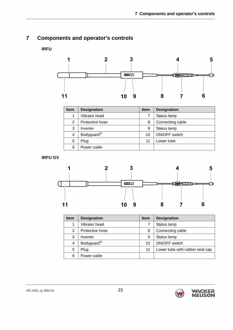
IRFU
IRFU GV
Item Designation Item Designation
1 Vibrator head 7 Status lamp
2 Protective hose 8 Connecting cable
3 Inverter 9 Status lamp
4 Bodyguard® 10 ON/OFF switch
5 Plug 11 Lower tube
6 Power cable
Item Designation Item Designation
1 Vibrator head 7 Status lamp
2 Protective hose 8 Connecting cable
3 Inverter 9 Status lamp
4 Bodyguard® 10 ON/OFF switch
5 Plug 11 Lower tube with rubber seal cap
6 Power cable
7 Components and operator's controls
24 100_0101_cp_0001.fm
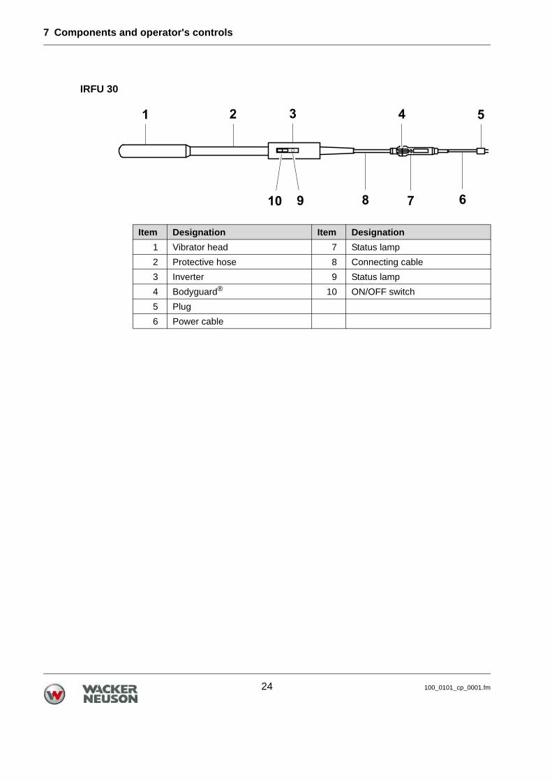
IRFU 30
Item Designation Item Designation
1 Vibrator head 7 Status lamp
2 Protective hose 8 Connecting cable
3 Inverter 9 Status lamp
4 Bodyguard® 10 ON/OFF switch
5 Plug
6 Power cable
8 Transport
100_0101_tr_0001.fm 25
8 Transport
Transporting the machine
1. Switch off the machine via the ON/OFF switch.
2. Wait until the machine has come to a complete standstill.
3. Pull the plug from the plug receptacle.
4. Place the machine on or into a suitable means of transport.
5. Roll up the power cable and the protective hose.
Note: Do not kink the protective hose and power cable.
6. Secure the machine against falling and sliding.
WARNINGImproper handling can result in injury or serious material damage. Read and follow all safety information of this operator's manual, see chapter
Safety.
WARNINGHot vibrator head.Touching it can cause burns. Only touch the vibrator head once the engine has cooled down. Wear protective gloves.
9 Use and operation
26 100_0101_op_0001.fm
9 Use and operation
9.1 Prior to starting the machine
After unpacking, the machine is ready for operation.
Checking the machine
Check the machine and all components for damages.
Damage to the protective hose and the power cable.
Checking the mains
Check if mains or power distribution on the construction site have the correct operating voltage (see nameplate of the machine or chapter Technical Data).
Check if mains or power distribution on the constructions site are protected in accordance with current standards and regulations.
9.2 Starting up
WARNINGImproper handling can result in injury or serious material damage. Read and follow all safety information of this operator's manual, see chapter
Safety.
WARNINGDamaged insulation.Danger of electrocution! Do not kink or damage the protective hose and power cable.
9 Use and operation
100_0101_op_0001.fm 27
Connecting the machine to the electric power supply
Note: The machine may only be connected to AC single phase, connection val-ues see chapter Technical Data.
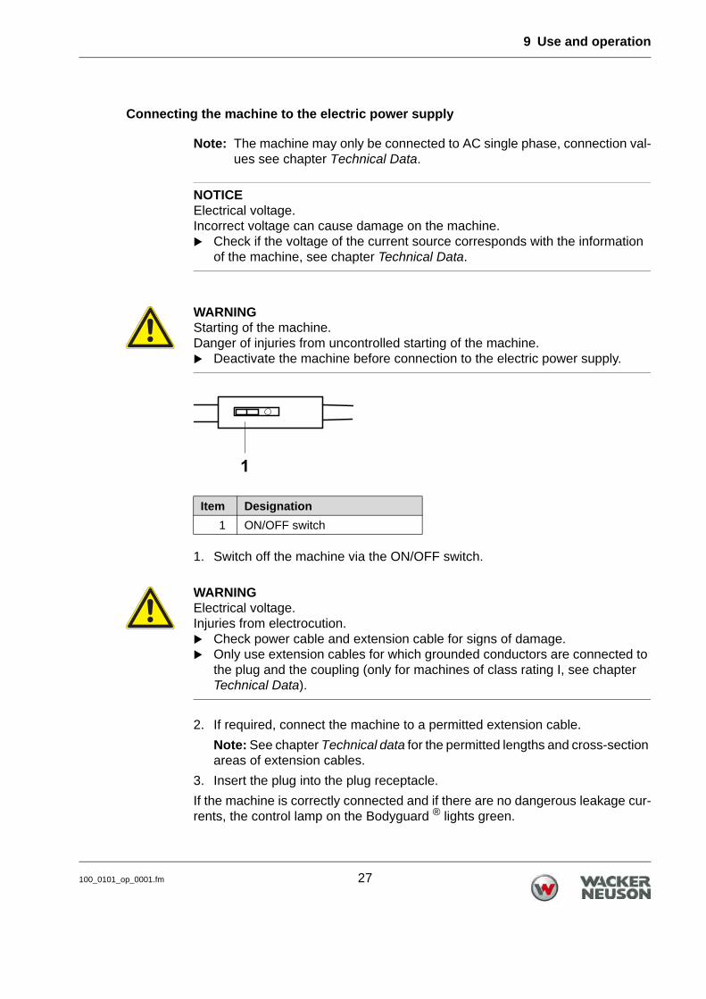
1. Switch off the machine via the ON/OFF switch.
2. If required, connect the machine to a permitted extension cable.
Note: See chapter Technical data for the permitted lengths and cross-section areas of extension cables.
3. Insert the plug into the plug receptacle.
If the machine is correctly connected and if there are no dangerous leakage cur-rents, the control lamp on the Bodyguard ® lights green.
NOTICEElectrical voltage.Incorrect voltage can cause damage on the machine. Check if the voltage of the current source corresponds with the information
of the machine, see chapter Technical Data.
WARNINGStarting of the machine.Danger of injuries from uncontrolled starting of the machine. Deactivate the machine before connection to the electric power supply.
Item Designation
1 ON/OFF switch
WARNINGElectrical voltage.Injuries from electrocution. Check power cable and extension cable for signs of damage. Only use extension cables for which grounded conductors are connected to
the plug and the coupling (only for machines of class rating I, see chapter Technical Data).

9 Use and operation
28 100_0101_op_0001.fm
Switching on the machine
1. Use the protective hose to hold the machine near the vibrator head.
2. Switch on the machine via the ON/OFF switch.
If the machine is ready for operation, the control lamp on the inverter lights green.
Item Designation
1 Control lamp
2 ON/OFF switch
9 Use and operation
100_0101_op_0001.fm 29
Compacting fresh concrete
1. Hold machine at the protective hose with both hands.
2. Quickly immerse the vibrator head in the fresh concrete, hold it for several seconds and slowly pull it out again.
3. Immerse the vibrator head in all areas of the formwork and compact the fresh concrete.
Note:
Compact especially intensively in the area of formwork corners. In these ar-eas, the reinforcement rate is the highest.
Avoid contact of the vibrator head with the concrete reinforcement. The fol-lowing damages are possible if the vibrator head comes into contact with the concrete reinforcement: The connection of the concrete to the reinforcement can be lost. The machine can be damaged.
The result of the compacting depends on the following points: Holding time of the vibrator head in the concrete. Diameter of the vibrator head. Consistency of the concrete. Reinforcement rate.
If you use a vibrator head with a smaller diameter, the compacting time to achieve the same results as with a vibrator head with a larger diameter will increase.
Indications that the concrete is sufficiently compacted: The concrete no longer sets. Air bubbles no longer or rarely rise. The sound of the vibrator head is not changing anymore.
9 Use and operation
30 100_0101_op_0001.fm
9.3 Decommissioning
Switching off the machine
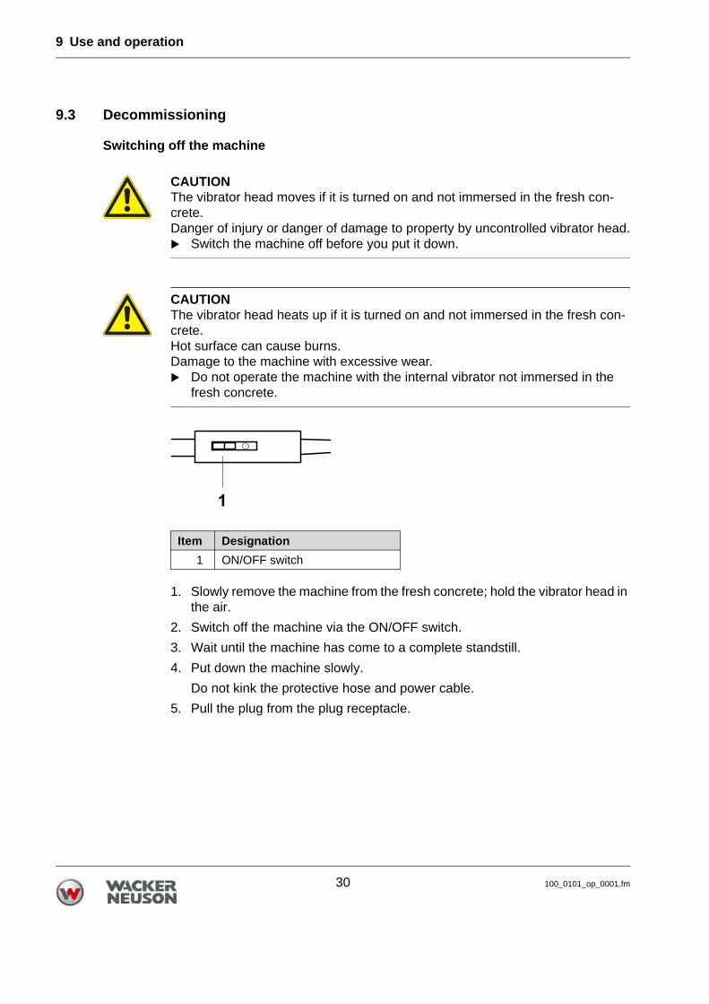
1. Slowly remove the machine from the fresh concrete; hold the vibrator head in the air.
2. Switch off the machine via the ON/OFF switch.
3. Wait until the machine has come to a complete standstill.
4. Put down the machine slowly.
Do not kink the protective hose and power cable.
5. Pull the plug from the plug receptacle.
CAUTIONThe vibrator head moves if it is turned on and not immersed in the fresh con-crete.Danger of injury or danger of damage to property by uncontrolled vibrator head. Switch the machine off before you put it down.
CAUTIONThe vibrator head heats up if it is turned on and not immersed in the fresh con-crete.Hot surface can cause burns.Damage to the machine with excessive wear. Do not operate the machine with the internal vibrator not immersed in the
fresh concrete.
Item Designation
1 ON/OFF switch
9 Use and operation
100_0101_op_0001.fm 31
9.4 Cleaning
Cleaning the machine
Clean the machine and all components with water after each use.
Note: You can remove concrete residuals by immersing the running machine into gravel.
10 Maintenance
32 100_0101_mt_0001.fm
10 Maintenance
10.1 Maintenance personnel qualifications
Qualifications for maintenance work
The maintenance tasks described in this operator's manual may be performed by any responsible user unless otherwise stated.
Some maintenance tasks may only be performed by specially trained personnel or by the service staff of your Wacker Neuson contact — these are specifically noted.
10.2 Maintenance schedule
Note: The time intervals mentioned here are reference values for normal oper-ation. For extreme operation, e.g. continuous use, the service intervals should be halved.
WARNINGImproper handling can result in injury or serious material damage. Read and follow all safety instructions of this operator's manual, see chapter
Safety.
WARNINGImproper handling may cause a danger to life by electrocution. Only a qualified electrician is permitted to open the machine, perform re-
pairs, and perform a subsequent safety check in accordance with applicable regulations.
Task Daily be-fore oper-ation
Every 100 hrs.
Visual inspection of all parts for damage.
Check the wear dimensions.
Change oil in vibrator head *
* Have these tasks carried out by the service department of your Wacker Neuson representative person.
10 Maintenance
100_0101_mt_0001.fm 33
10.3 Maintenance work
Working in the workshop
Perform maintenance work in a workshop on a workbench. This has the following benefits:
Protection of the machine of contamination on the construction site. A level and clean work surface makes work easier. There is a better overview over small parts and they are not lost as easily.
Visual inspection for damage
Check all machine parts and components for damage.
Check the tightness of the switch diaphragm for the ON/OFF switch.
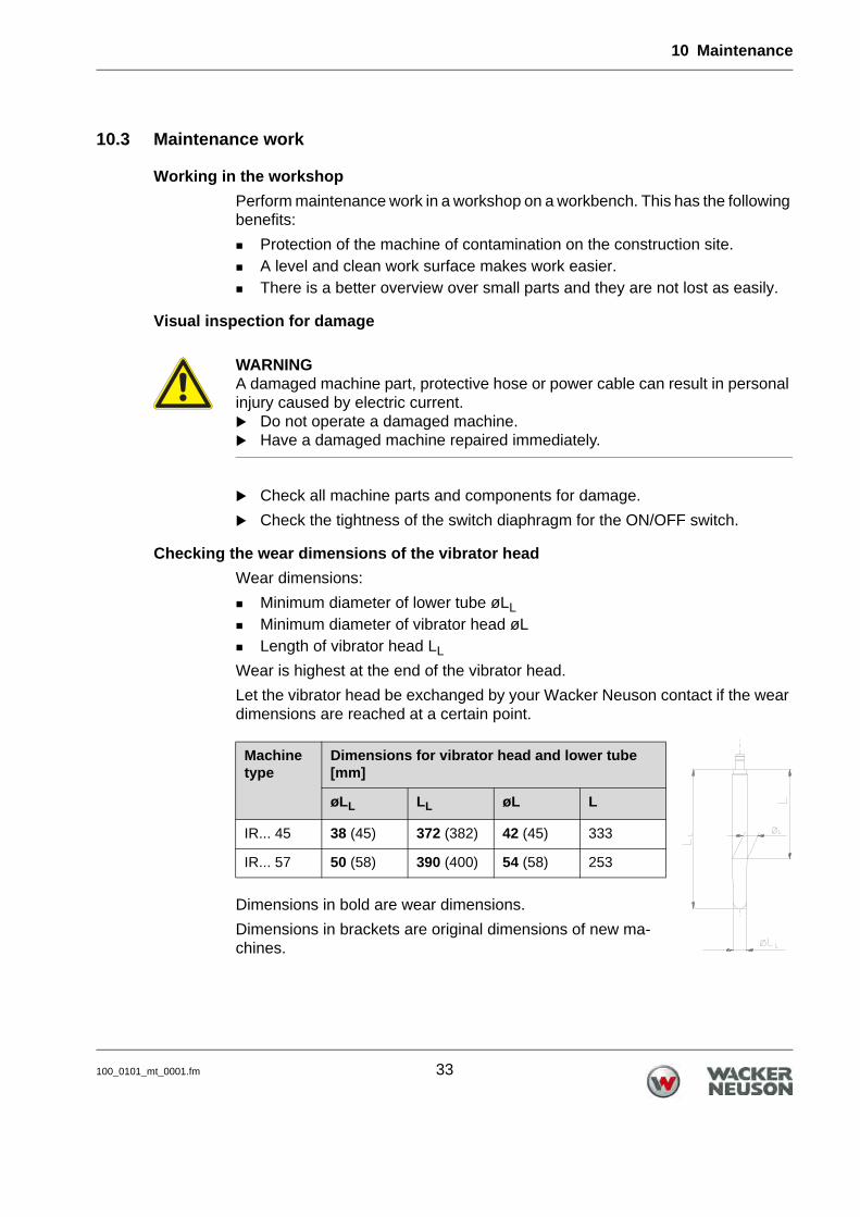
Checking the wear dimensions of the vibrator head
Wear dimensions:
Minimum diameter of lower tube øLL
Minimum diameter of vibrator head øL Length of vibrator head LL
Wear is highest at the end of the vibrator head.
Let the vibrator head be exchanged by your Wacker Neuson contact if the wear dimensions are reached at a certain point.
Dimensions in bold are wear dimensions.
Dimensions in brackets are original dimensions of new ma-chines.
WARNINGA damaged machine part, protective hose or power cable can result in personal injury caused by electric current. Do not operate a damaged machine. Have a damaged machine repaired immediately.
Machine type
Dimensions for vibrator head and lower tube [mm]
øLL LL øL L
IR... 45 38 (45) 372 (382) 42 (45) 333
IR... 57 50 (58) 390 (400) 54 (58) 253

10 Maintenance
34 100_0101_mt_0001.fm
Changing the oil in the vibrator head
Take the machine to your Wacker Neuson representative to change the oil in the vibrator head.
11 Malfunctions
100_0101_ts_0001.fm 35
11 Malfunctions
Please refer to the following table if the machine does not work properly. It con-tains potential faults, their causes and remedies.
11.1 Bodyguard®
11.2 Inverter
Malfunction Cause Remedy
Control lamp lights red.The line voltage is applied.
The Bodyguard® has turned off the machine.
Machine malfunction.
1. Pull the plug from the plug re-ceptacle.
2. Check power cable for dam-age – if damaged, have it re-placed. *
3. Insert the plug into the plug receptacle.
If the fault is not remedied, have the machine repaired. *
* Have these tasks carried out by the service department of your Wacker Neuson representative per-son.
Water in inverter. Defect in the vibrator head.
Have the machine repaired. *
Control lamp does not light up. No line voltage. 1. Pull the plug from the plug re-ceptacle.
2. Check power cable for dam-age – if damaged, have it re-placed. *
3. Insert the plug into the plug receptacle.
Bodyguard® is defective. Have the machine repaired. *
Malfunction Cause Remedy
Control lamp lights red. Line voltage is interrupted. Incorrect line voltage.
Inverter starts automatically as soon as the correct line voltage is available (again).
Control lamp flashes red. Defect in the vibrator head. Have the machine repaired. *
11 Malfunctions
36 100_0101_ts_0001.fm
Control lamp flashes red twice. Inverter has switched off due to excess temperature.
1. Allow the inverter to cool down.
2. Carry out a reset:Switch the machine off and on again.
Control lamp flashes red three times (for a short period).
The Bodyguard® has turned off the machine.
1. Pull out the plug.2. Eliminate the fault or have it
eliminated. *3. Insert the plug.
No Bodyguard® present. Have the machine reset to its original condition. *
* Have these tasks carried out by the service department of your Wacker Neusoncontact person.
Malfunction Cause Remedy
12 Disposal
100_0000_0004.fm 37
12 Disposal
12.1 Disposal of waste electrical and electronic equipment
For customers in EU countries
This device is subject to the European Directive on waste electrical and electron-ic equipment (WEEE) and the corresponding national legislation. The WEEE di-rective outlines the procedure for handling electrical waste equipment across the EU.
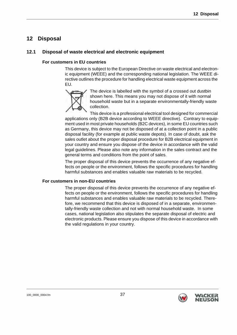
The device is labelled with the symbol of a crossed out dustbin shown here. This means you may not dispose of it with normal household waste but in a separate environmentally-friendly waste collection.
This device is a professional electrical tool designed for commercial applications only (B2B device according to WEEE directive). Contrary to equip-ment used in most private households (B2C devices), in some EU countries such as Germany, this device may not be disposed of at a collection point in a public disposal facility (for example at public waste depots). In case of doubt, ask the sales outlet about the proper disposal procedure for B2B electrical equipment in your country and ensure you dispose of the device in accordance with the valid legal guidelines. Please also note any information in the sales contract and the general terms and conditions from the point of sales.
The proper disposal of this device prevents the occurrence of any negative ef-fects on people or the environment, follows the specific procedures for handling harmful substances and enables valuable raw materials to be recycled.
For customers in non-EU countries
The proper disposal of this device prevents the occurrence of any negative ef-fects on people or the environment, follows the specific procedures for handling harmful substances and enables valuable raw materials to be recycled. There-fore, we recommend that this device is disposed of in a separate, environmen-tally-friendly waste collection and not with normal household waste. In some cases, national legislation also stipulates the separate disposal of electric and electronic products. Please ensure you dispose of this device in accordance with the valid regulations in your country.
13 Technical data
38 100_0101_td_0001.fm
13 Technical data
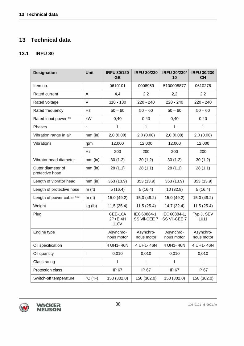
13.1 IRFU 30
Designation Unit IRFU 30/120 GB
IRFU 30/230 IRFU 30/230/10
IRFU 30/230 CH
Item no. 0610101 0008959 5100008877 0610278
Rated current A 4,4 2,2 2,2 2,2
Rated voltage V 110 - 130 220 - 240 220 - 240 220 - 240
Rated frequency Hz 50 – 60 50 – 60 50 – 60 50 – 60
Rated input power ** kW 0,40 0,40 0,40 0,40
Phases ~ 1 1 1 1
Vibration range in air mm (in) 2,0 (0.08) 2,0 (0.08) 2,0 (0.08) 2,0 (0.08)
Vibrations rpm 12,000 12,000 12,000 12,000
Hz 200 200 200 200
Vibrator head diameter mm (in) 30 (1.2) 30 (1.2) 30 (1.2) 30 (1.2)
Outer diameter of protective hose
mm (in) 28 (1.1) 28 (1.1) 28 (1.1) 28 (1.1)
Length of vibrator head mm (in) 353 (13.9) 353 (13.9) 353 (13.9) 353 (13.9)
Length of protective hose m (ft) 5 (16.4) 5 (16.4) 10 (32.8) 5 (16.4)
Length of power cable *** m (ft) 15,0 (49.2) 15,0 (49.2) 15,0 (49.2) 15,0 (49.2)
Weight kg (lb) 11,5 (25.4) 11,5 (25.4) 14,7 (32.4) 11,5 (25.4)
Plug CEE-16A 2P+E 4H
110V
IEC 60884-1, SS Vll-CEE 7
IEC 60884-1, SS Vll-CEE 7
Typ J, SEV 1011
Engine type Asynchro-nous motor
Asynchro-nous motor
Asynchro-nous motor
Asynchro-nous motor
Oil specification 4 UH1- 46N 4 UH1- 46N 4 UH1- 46N 4 UH1- 46N
Oil quantity l 0,010 0,010 0,010 0,010
Class rating l l l l
Protection class IP 67 IP 67 IP 67 IP 67
Switch-off temperature °C (°F) 150 (302.0) 150 (302.0) 150 (302.0) 150 (302.0)

13 Technical data
100_0101_td_0001.fm 39
Storage temperature range
°C (°F) -20 – +60(-4 - +140)
-20 – +60(-4 - +140)
-20 – +60(-4 - +140)
-20 – +60(-4 - +140)
Operating temperature range
°C (°F) -10 – +40(+14 – +104)
-10 – +40(+14 – +104)
-10 – +40(+14 – +104)
-10 – +40(+14 – +104)
Sound pressure level LpA * dB(A) 76,0 76,0 79,0 76,0
Standard DIN EN ISO 11201
Vibration total value ahv * m/s2
(ft/s2)0,7
(2.3)0,7
(2.3)0,7
(2.3)0,7
(2.3)
Standard DIN EN ISO 20643
Uncertainty of measurement of vibration total value ahv *
m/s2
(ft/s2)0,5
(1.6)0,5
(1.6)0,5
(1.6)0,5
(1.6)
* These measurements were taken when the machine was operated freely suspended in air.
** The rated power is the active power consumed during nominal operation.
*** Cable length: Length including plug to the inverter.
Designation Unit IRFU 30/120 GB
IRFU 30/230 IRFU 30/230/10
IRFU 30/230 CH
13 Technical data
40 100_0101_td_0001.fm
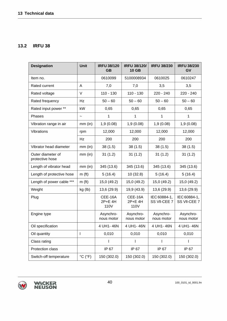
13.2 IRFU 38
Designation Unit IRFU 38/120 GB
IRFU 38/120/10 GB
IRFU 38/230 IRFU 38/230 GV
Item no. 0610099 5100008934 0610025 0610247
Rated current A 7,0 7,0 3,5 3,5
Rated voltage V 110 - 130 110 - 130 220 - 240 220 - 240
Rated frequency Hz 50 – 60 50 – 60 50 – 60 50 – 60
Rated input power ** kW 0,65 0,65 0,65 0,65
Phases ~ 1 1 1 1
Vibration range in air mm (in) 1,9 (0.08) 1,9 (0.08) 1,9 (0.08) 1,9 (0.08)
Vibrations rpm 12,000 12,000 12,000 12,000
Hz 200 200 200 200
Vibrator head diameter mm (in) 38 (1.5) 38 (1.5) 38 (1.5) 38 (1.5)
Outer diameter of protective hose
mm (in) 31 (1.2) 31 (1.2) 31 (1.2) 31 (1.2)
Length of vibrator head mm (in) 345 (13.6) 345 (13.6) 345 (13.6) 345 (13.6)
Length of protective hose m (ft) 5 (16.4) 10 (32.8) 5 (16.4) 5 (16.4)
Length of power cable *** m (ft) 15,0 (49.2) 15,0 (49.2) 15,0 (49.2) 15,0 (49.2)
Weight kg (lb) 13,6 (29.9) 19,9 (43.9) 13,6 (29.9) 13,6 (29.9)
Plug CEE-16A 2P+E 4H
110V
CEE-16A 2P+E 4H
110V
IEC 60884-1, SS Vll-CEE 7
IEC 60884-1, SS Vll-CEE 7
Engine type Asynchro-nous motor
Asynchro-nous motor
Asynchro-nous motor
Asynchro-nous motor
Oil specification 4 UH1- 46N 4 UH1- 46N 4 UH1- 46N 4 UH1- 46N
Oil quantity l 0,010 0,010 0,010 0,010
Class rating l l l l
Protection class IP 67 IP 67 IP 67 IP 67
Switch-off temperature °C (°F) 150 (302.0) 150 (302.0) 150 (302.0) 150 (302.0)
13 Technical data
100_0101_td_0001.fm 41
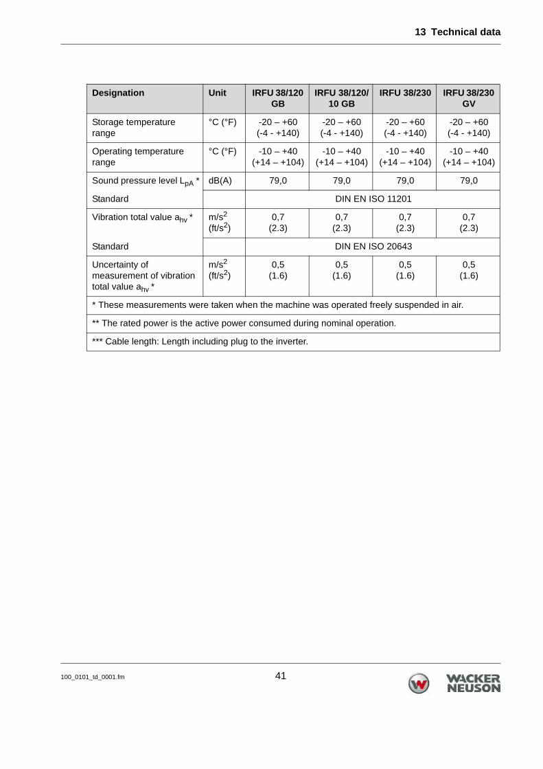
Storage temperature range
°C (°F) -20 – +60(-4 - +140)
-20 – +60(-4 - +140)
-20 – +60(-4 - +140)
-20 – +60(-4 - +140)
Operating temperature range
°C (°F) -10 – +40(+14 – +104)
-10 – +40(+14 – +104)
-10 – +40(+14 – +104)
-10 – +40(+14 – +104)
Sound pressure level LpA * dB(A) 79,0 79,0 79,0 79,0
Standard DIN EN ISO 11201
Vibration total value ahv * m/s2
(ft/s2)0,7
(2.3)0,7
(2.3)0,7
(2.3)0,7
(2.3)
Standard DIN EN ISO 20643
Uncertainty of measurement of vibration total value ahv *
m/s2
(ft/s2)0,5
(1.6)0,5
(1.6)0,5
(1.6)0,5
(1.6)
* These measurements were taken when the machine was operated freely suspended in air.
** The rated power is the active power consumed during nominal operation.
*** Cable length: Length including plug to the inverter.
Designation Unit IRFU 38/120 GB
IRFU 38/120/10 GB
IRFU 38/230 IRFU 38/230 GV

13 Technical data
42 100_0101_td_0001.fm
Designation Unit IRFU 38/230/10 IRFU 38/230 CH
Item no. 5100008871 0610245
Rated current A 3,5 3,5
Rated voltage V 220 - 240 220 - 240
Rated frequency Hz 50 – 60 50 – 60
Rated input power ** kW 0,65 0,65
Phases ~ 1 1
Vibration range in air mm (in) 1,9 (0.08) 1,9 (0.08)
Vibrations rpm 12,000 12,000
Hz 200 200
Vibrator head diameter mm (in) 38 (1.5) 38 (1.5)
Outer diameter of protective hose
mm (in) 31 (1.2) 31 (1.2)
Length of vibrator head mm (in) 345 (13.6) 345 (13.6)
Length of protective hose m (ft) 10 (32.8 5 (16.4)
Length of power cable *** m (ft) 15,0 (49.2) 15,0 (49.2)
Weight kg (lb) 18,7 (41.2) 13,6 (29.9)
Plug IEC 60884-1, SS Vll-CEE 7 Typ J, SEV 1011
Engine type Asynchronous motor Asynchronous motor
Oil specification 4 UH1- 46N 4 UH1- 46N
Oil quantity l 0,010 0,010
Class rating l l
Protection class IP 67 IP 67
Switch-off temperature °C (°F) 150 (302.0) 150 (302.0)
Storage temperature range
°C (°F) -20 – +60(-4 - +140)
-20 – +60(-4 - +140)
Operating temperature range
°C (°F) -10 – +40(+14 – +104)
-10 – +40(+14 – +104)
Sound pressure level LpA * dB(A) 79,0 79,0
Standard DIN EN ISO 11201

13 Technical data
100_0101_td_0001.fm 43
Vibration total value ahv * m/s2
(ft/s2)0,7
(2.3)0,7
(2.3)
Standard DIN EN ISO 20643
Uncertainty of measurement of vibration total value ahv *
m/s2
(ft/s2)0,5
(1.6)0,5
(1.6)
* These measurements were taken when the machine was operated freely suspended in air.
** The rated power is the active power consumed during nominal operation.
*** Cable length: Length including plug to the inverter.
Designation Unit IRFU 38/230/10 IRFU 38/230 CH

13 Technical data
44 100_0101_td_0001.fm
13.3 IRFU 45
Designation Unit IRFU 45/120 GB
IRFU 45/120/10 GB
IRFU 45/230 IRFU 45/230 GV
Item no. 0610097 5100008935 0610024 0610255
Rated current A 9,6 9,6 4,8 4,8
Rated voltage V 110 - 130 110 - 130 220 - 240 220 - 240
Rated frequency Hz 50 – 60 50 – 60 50 – 60 50 – 60
Rated input power ** kW 0,88 0,88 0,88 0,88
Phases ~ 1 1 1 1
Vibration range in air mm (in) 2,3 (0.09) 2,3 (0.09) 2,3 (0.09) 2,3 (0.09)
Vibrations rpm 12,000 12,000 12,000 12,000
Hz 200 200 200 200
Vibrator head diameter mm (in) 45 (1.8) 45 (1.8) 45 (1.8) 45 (1.8)
Outer diameter of protective hose
mm (in) 31 (1.2) 31 (1.2) 31 (1.2) 31 (1.2)
Length of vibrator head mm (in) 382 (15.0) 382 (15.0) 382 (15.0) 382 (15.0)
Length of protective hose m (ft) 5 (16.4) 10 (32.8) 5 (16.4) 5 (16.4)
Length of power cable *** m (ft) 15,0 (49.2) 15,0 (49.2) 15,0 (49.2) 15,0 (49.2)
Weight kg (lb) 16,0 (35.3) 20,9 (46.1 16,0 (35.3) 16,0 (35.3)
Plug CEE-16A 2P+E 4H
110V
CEE-16A 2P+E 4H
110V
IEC 60884-1, SS Vll-CEE 7
IEC 60884-1, SS Vll-CEE 7
Engine type Asynchro-nous motor
Asynchro-nous motor
Asynchro-nous motor
Asynchro-nous motor
Oil specification 4 UH1- 46N 4 UH1- 46N 4 UH1- 46N 4 UH1- 46N
Oil quantity l 0,010 0,010 0,010 0,010
Class rating l l l l
Protection class IP 67 IP 67 IP 67 IP 67
Switch-off temperature °C (°F) 150 (302.0) 150 (302.0) 150 (302.0) 150 (302.0)
Storage temperature range
°C (°F) -20 – +60(-4 - +140)
-20 – +60(-4 - +140)
-20 – +60(-4 - +140)
-20 – +60(-4 - +140)

13 Technical data
100_0101_td_0001.fm 45
Operating temperature range
°C (°F) -10 – +40(+14 – +104)
-10 – +40(+14 – +104)
-10 – +40(+14 – +104)
-10 – +40(+14 – +104)
Sound pressure level LpA * dB(A) 79,0 79,0 79,0 79,0
Standard DIN EN ISO 11201
Vibration total value ahv * m/s2
(ft/s2)1,7
(5.6)1,7
(5.6)1,7
(5.6)1,7
(5.6)
Standard DIN EN ISO 20643
Uncertainty of measurement of vibration total value ahv *
m/s2
(ft/s2)0,5
(1.6)0,5
(1.6)0,5
(1.6)0,5
(1.6)
* These measurements were taken when the machine was operated freely suspended in air.
** The rated power is the active power consumed during nominal operation.
*** Cable length: Length including plug to the inverter.
Designation Unit IRFU 45/120 GB
IRFU 45/120/10 GB
IRFU 45/230 IRFU 45/230 GV
13 Technical data
46 100_0101_td_0001.fm
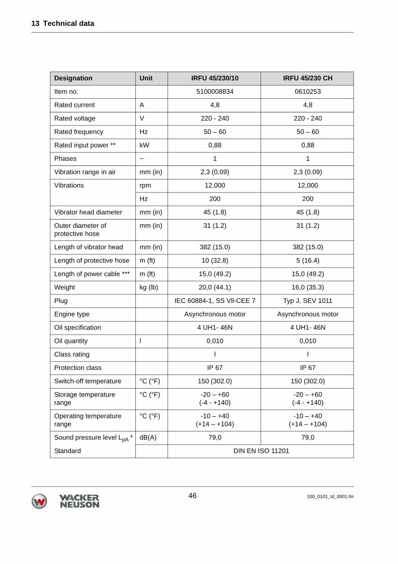
Designation Unit IRFU 45/230/10 IRFU 45/230 CH
Item no. 5100008834 0610253
Rated current A 4,8 4,8
Rated voltage V 220 - 240 220 - 240
Rated frequency Hz 50 – 60 50 – 60
Rated input power ** kW 0,88 0,88
Phases ~ 1 1
Vibration range in air mm (in) 2,3 (0.09) 2,3 (0.09)
Vibrations rpm 12,000 12,000
Hz 200 200
Vibrator head diameter mm (in) 45 (1.8) 45 (1.8)
Outer diameter of protective hose
mm (in) 31 (1.2) 31 (1.2)
Length of vibrator head mm (in) 382 (15.0) 382 (15.0)
Length of protective hose m (ft) 10 (32.8) 5 (16.4)
Length of power cable *** m (ft) 15,0 (49.2) 15,0 (49.2)
Weight kg (lb) 20,0 (44.1) 16,0 (35.3)
Plug IEC 60884-1, SS Vll-CEE 7 Typ J, SEV 1011
Engine type Asynchronous motor Asynchronous motor
Oil specification 4 UH1- 46N 4 UH1- 46N
Oil quantity l 0,010 0,010
Class rating l l
Protection class IP 67 IP 67
Switch-off temperature °C (°F) 150 (302.0) 150 (302.0)
Storage temperature range
°C (°F) -20 – +60(-4 - +140)
-20 – +60(-4 - +140)
Operating temperature range
°C (°F) -10 – +40(+14 – +104)
-10 – +40(+14 – +104)
Sound pressure level LpA * dB(A) 79,0 79,0
Standard DIN EN ISO 11201
13 Technical data
100_0101_td_0001.fm 47
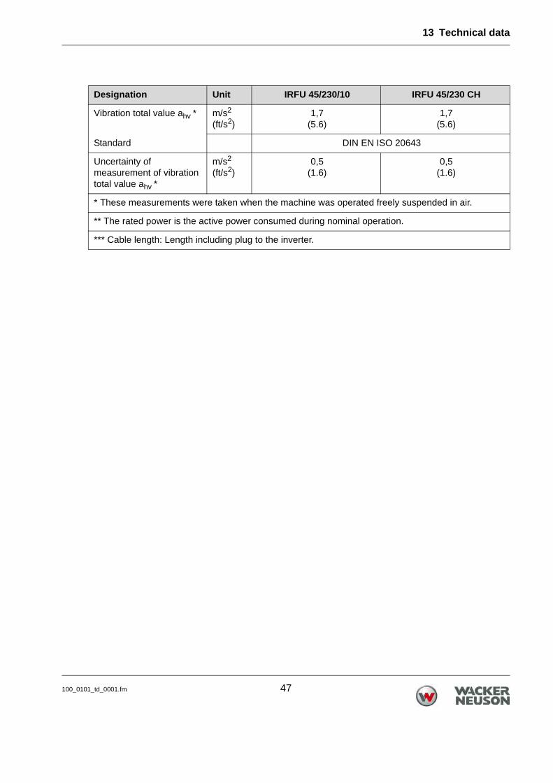
Vibration total value ahv * m/s2
(ft/s2)1,7
(5.6)1,7
(5.6)
Standard DIN EN ISO 20643
Uncertainty of measurement of vibration total value ahv *
m/s2
(ft/s2)0,5
(1.6)0,5
(1.6)
* These measurements were taken when the machine was operated freely suspended in air.
** The rated power is the active power consumed during nominal operation.
*** Cable length: Length including plug to the inverter.
Designation Unit IRFU 45/230/10 IRFU 45/230 CH

13 Technical data
48 100_0101_td_0001.fm
13.4 IRFU 57
Designation Unit IRFU 57/120 GB
IRFU 57/120/10 GB
IRFU 57/230 IRFU 57/230 GV
Item no. 0610008 5100008936 0610007 0610265
Rated current A 12,0 12,0 6,0 6,0
Rated voltage V 110 - 130 110 - 130 220 - 240 220 - 240
Rated frequency Hz 50 – 60 50 – 60 50 – 60 50 – 60
Rated input power ** kW 1,10 1,10 1,10 1,10
Phases ~ 1 1 1 1
Vibration range in air mm (in) 2,5 (0.09) 2,5 (0.09) 2,5 (0.09) 2,5 (0.09)
Vibrations rpm 12,000 12,000 12,000 12,000
Hz 200 200 200 200
Vibrator head diameter mm (in) 58 (2.3) 58 (2.3) 58 (2.3) 58 (2.3)
Outer diameter of protective hose
mm (in) 40 (1.6) 40 (1.6) 40 (1.6) 40 (1.6)
Length of vibrator head mm (in) 400 (15.7) 400 (15.7) 400 (15.7) 400 (15.7)
Length of protective hose m (ft) 5 (16.4) 10 (32.8) 5 (16.4) 5 (16.4)
Length of power cable *** m (ft) 15,0 (49.2) 15,0 (49.2) 15,0 (49.2) 15,0 (49.2)
Weight kg (lb) 19,8 (43.7) 23,10 (50.9) 19,8 (43.7) 19,8 (43.7)
Plug CEE-16A 2P+E 4H
110V
CEE-16A 2P+E 4H
110V
IEC 60884-1, SS Vll-
CEE 7
IEC 60884-1, SS Vll-
CEE 7
Engine type Asynchro-nous motor
Asynchro-nous motor
Asynchro-nous motor
Asynchro-nous motor
Oil specification 4 UH1- 46N 4 UH1- 46N 4 UH1- 46N 4 UH1- 46N
Oil quantity l 0,010 0,010 0,010 0,010
Class rating l l l l
Protection class IP 67 IP 67 IP 67 IP 67
Switch-off temperature °C (°F) 150 (302.0) 150 (302.0) 150 (302.0) 150 (302.0)
Storage temperature range
°C (°F) -20 – +60(-4 - +140)
-20 – +60(-4 - +140)
-20 – +60(-4 - +140)
-20 – +60(-4 - +140)
13 Technical data
100_0101_td_0001.fm 49
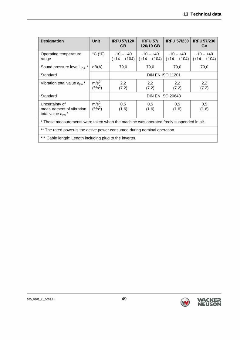
Operating temperature range
°C (°F) -10 – +40(+14 – +104)
-10 – +40(+14 – +104)
-10 – +40(+14 – +104)
-10 – +40(+14 – +104)
Sound pressure level LpA * dB(A) 79,0 79,0 79,0 79,0
Standard DIN EN ISO 11201
Vibration total value ahv * m/s2
(ft/s2)2,2
(7.2)2,2
(7.2)2,2
(7.2)2,2
(7.2)
Standard DIN EN ISO 20643
Uncertainty of measurement of vibration total value ahv *
m/s2
(ft/s2)0,5
(1.6)0,5
(1.6)0,5
(1.6)0,5
(1.6)
* These measurements were taken when the machine was operated freely suspended in air.
** The rated power is the active power consumed during nominal operation.
*** Cable length: Length including plug to the inverter.
Designation Unit IRFU 57/120 GB
IRFU 57/120/10 GB
IRFU 57/230 IRFU 57/230 GV

13 Technical data
50 100_0101_td_0001.fm
Designation Unit IRFU 57/230/10 IRFU 57/230 CH
Item no. 5100008835 0610263
Rated current A 6,0 6,00
Rated voltage V 220 - 240 220 - 240
Rated frequency Hz 50 – 60 50 – 60
Rated input power ** kW 1,10 1,10
Phases ~ 1 1
Vibration range in air mm (in) 2,5 (0.09) 2,5 (0.09)
Vibrations rpm 12,000 12,000
Hz 200 200
Vibrator head diameter mm (in) 58 (2.3) 58 (2.3)
Outer diameter of protective hose
mm (in) 40 (1.6) 40 (1.6)
Length of vibrator head mm (in) 400 (15.7) 400 (15.7)
Length of protective hose m (ft) 10 (32.8) 5 (16.4)
Length of power cable *** m (ft) 15,0 (49.2) 15,0 (49.2)
Weight kg (lb) 25,3 (55.8) 19,8 (43.7)
Plug IEC 60884-1, SS Vll-CEE 7 Typ J, SEV 1011
Engine type Asynchronous motor Asynchronous motor
Oil specification 4 UH1- 46N 4 UH1- 46N
Oil quantity l 0,010 0,010
Class rating l l
Protection class IP 67 IP 67
Switch-off temperature °C (°F) 150 (302.0) 150 (302.0)
Storage temperature range
°C (°F) -20 – +60(-4 - +140)
-20 – +60(-4 - +140)
Operating temperature range
°C (°F) -10 – +40(+14 – +104)
-10 – +40(+14 – +104)
Sound pressure level LpA * dB(A) 79,0 79,0
Standard DIN EN ISO 11201

13 Technical data
100_0101_td_0001.fm 51
Vibration total value ahv * m/s2
(ft/s2)2,2
(7.2)2,2
(7.2)
Standard DIN EN ISO 20643
Uncertainty of measurement of vibration total value ahv *
m/s2
(ft/s2)0,5
(1.6)0,5
(1.6)
* These measurements were taken when the machine was operated freely suspended in air.
** The rated power is the active power consumed during nominal operation.
*** Cable length: Length including plug to the inverter.
Designation Unit IRFU 57/230/10 IRFU 57/230 CH
13 Technical data
52 100_0101_td_0001.fm
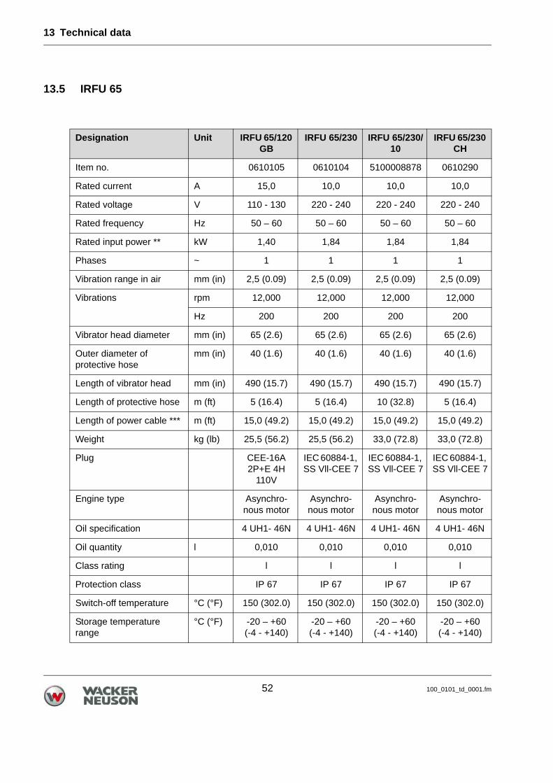
13.5 IRFU 65
Designation Unit IRFU 65/120 GB
IRFU 65/230 IRFU 65/230/10
IRFU 65/230 CH
Item no. 0610105 0610104 5100008878 0610290
Rated current A 15,0 10,0 10,0 10,0
Rated voltage V 110 - 130 220 - 240 220 - 240 220 - 240
Rated frequency Hz 50 – 60 50 – 60 50 – 60 50 – 60
Rated input power ** kW 1,40 1,84 1,84 1,84
Phases ~ 1 1 1 1
Vibration range in air mm (in) 2,5 (0.09) 2,5 (0.09) 2,5 (0.09) 2,5 (0.09)
Vibrations rpm 12,000 12,000 12,000 12,000
Hz 200 200 200 200
Vibrator head diameter mm (in) 65 (2.6) 65 (2.6) 65 (2.6) 65 (2.6)
Outer diameter of protective hose
mm (in) 40 (1.6) 40 (1.6) 40 (1.6) 40 (1.6)
Length of vibrator head mm (in) 490 (15.7) 490 (15.7) 490 (15.7) 490 (15.7)
Length of protective hose m (ft) 5 (16.4) 5 (16.4) 10 (32.8) 5 (16.4)
Length of power cable *** m (ft) 15,0 (49.2) 15,0 (49.2) 15,0 (49.2) 15,0 (49.2)
Weight kg (lb) 25,5 (56.2) 25,5 (56.2) 33,0 (72.8) 33,0 (72.8)
Plug CEE-16A 2P+E 4H
110V
IEC 60884-1, SS Vll-CEE 7
IEC 60884-1, SS Vll-CEE 7
IEC 60884-1, SS Vll-CEE 7
Engine type Asynchro-nous motor
Asynchro-nous motor
Asynchro-nous motor
Asynchro-nous motor
Oil specification 4 UH1- 46N 4 UH1- 46N 4 UH1- 46N 4 UH1- 46N
Oil quantity l 0,010 0,010 0,010 0,010
Class rating l l l l
Protection class IP 67 IP 67 IP 67 IP 67
Switch-off temperature °C (°F) 150 (302.0) 150 (302.0) 150 (302.0) 150 (302.0)
Storage temperature range
°C (°F) -20 – +60(-4 - +140)
-20 – +60(-4 - +140)
-20 – +60(-4 - +140)
-20 – +60(-4 - +140)

13 Technical data
100_0101_td_0001.fm 53
Operating temperature range
°C (°F) -10 – +40(+14 – +104)
-10 – +40(+14 – +104)
-10 – +40(+14 – +104)
-10 – +40(+14 – +104)
Sound pressure level LpA * dB(A) 79,0 79,0 79,0 79,0
Standard DIN EN ISO 11201
Vibration total value ahv * m/s2
(ft/s2)3,4
(11.2)3,4
(11.2)3,4
(11.2)3,4
(11.2)
Standard DIN EN ISO 20643
Uncertainty of measurement of vibration total value ahv *
m/s2
(ft/s2)0,5
(1.6)0,5
(1.6)0,5
(1.6)0,5
(1.6)
* These measurements were taken when the machine was operated freely suspended in air.
** The rated power is the active power consumed during nominal operation.
*** Cable length: Length including plug to the inverter.
Designation Unit IRFU 65/120 GB
IRFU 65/230 IRFU 65/230/10
IRFU 65/230 CH

13 Technical data
54 100_0101_td_0001.fm
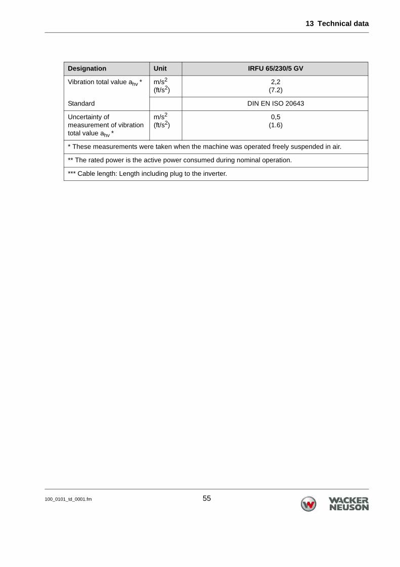
Designation Unit IRFU 65/230/5 GV
Item no. 5100015351
Rated current A 10,0
Rated voltage V 220 - 240
Rated frequency Hz 50 – 60
Rated input power ** kW 1,84
Phases ~ 1
Vibration range in air mm (in) 2,5
Vibrations rpm 12000
Hz 200
Vibrator head diameter mm (in) 65 (2.6)
Outer diameter of protective hose
mm (in) 40 (1.6)
Length of vibrator head mm (in) 490 (15.7)
Length of protective hose m (ft) 5 (16.4)
Length of power cable *** m (ft) 15,0 (49.2)
Weight kg (lb) 29,0 (63.9)
Plug CEE 7/7, Typ EF
Engine type Asynchronous motor
Oil specification 4 UH1- 46N
Oil quantity l 0,010
Class rating l
Protection class IP 67
Switch-off temperature °C (°F) 150 (302.0)
Storage temperature range
°C (°F) -20 – +60(-4 - +140)
Operating temperature range
°C (°F) -10 – +40(+14 – +104)
Sound pressure level LpA * dB(A) 79,0
Standard DIN EN ISO 11201
13 Technical data
100_0101_td_0001.fm 55
Vibration total value ahv * m/s2
(ft/s2)2,2
(7.2)
Standard DIN EN ISO 20643
Uncertainty of measurement of vibration total value ahv *
m/s2
(ft/s2)0,5
(1.6)
* These measurements were taken when the machine was operated freely suspended in air.
** The rated power is the active power consumed during nominal operation.
*** Cable length: Length including plug to the inverter.
Designation Unit IRFU 65/230/5 GV

13 Technical data
56 100_0101_td_0001.fm
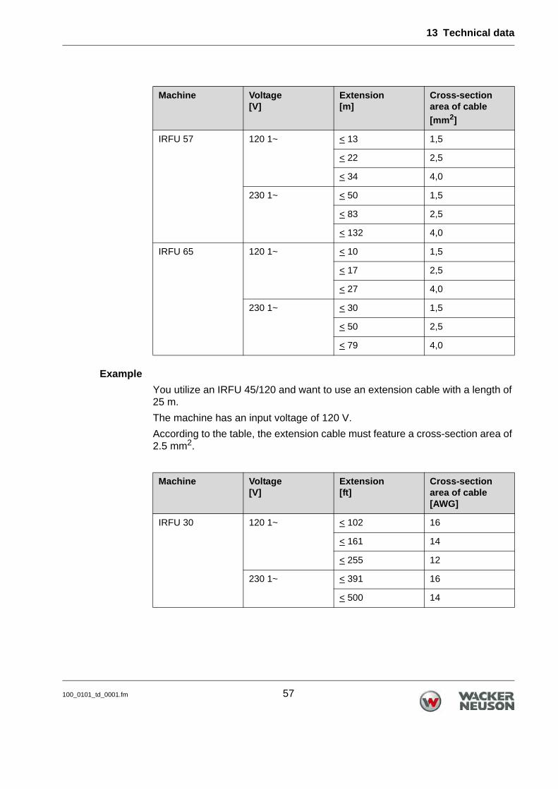
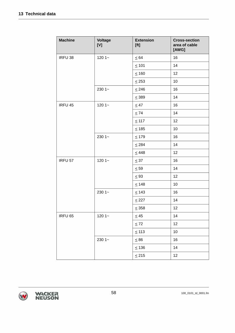
13.6 Extension cable
Only use permitted extension cables, see chapter Safety. Refer to the following table for the required cross-section area of the exten-
sion cable:
Note: Refer to the nameplate or the chapter Technical data (via the item num-ber) for the type designation and voltage rating of your machine.
WARNINGElectrical voltage.Injuries from electrocution. Check power cable and extension cable for signs of damage. Only use extension cables for which grounded conductors are connected to
the plug and the coupling (only for machines of class rating I, see chapter Technical Data).
Machine Voltage[V]
Extension[m]
Cross-section area of cable
[mm2]
IRFU 30 120 1~ < 36 1,5
< 59 2,5
< 94 4,0
230 1~ < 136 1,5
IRFU 38 120 1~ < 22 1,5
< 37 2,5
< 59 4,0
230 1~ < 86 1,5
< 142 2,5
IRFU 45 120 1~ < 16 1,5
< 27 2,5
< 43 4,0
230 1~ < 63 1,5
< 104 2,5
< 150 4,0
13 Technical data
100_0101_td_0001.fm 57
Example
You utilize an IRFU 45/120 and want to use an extension cable with a length of 25 m.
The machine has an input voltage of 120 V.
According to the table, the extension cable must feature a cross-section area of 2.5 mm2.
IRFU 57 120 1~ < 13 1,5
< 22 2,5
< 34 4,0
230 1~ < 50 1,5
< 83 2,5
< 132 4,0
IRFU 65 120 1~ < 10 1,5
< 17 2,5
< 27 4,0
230 1~ < 30 1,5
< 50 2,5
< 79 4,0
Machine Voltage[V]
Extension[ft]
Cross-section area of cable[AWG]
IRFU 30 120 1~ < 102 16
< 161 14
< 255 12
230 1~ < 391 16
< 500 14
Machine Voltage[V]
Extension[m]
Cross-section area of cable
[mm2]
13 Technical data
58 100_0101_td_0001.fm
IRFU 38 120 1~ < 64 16
< 101 14
< 160 12
< 253 10
230 1~ < 246 16
< 389 14
IRFU 45 120 1~ < 47 16
< 74 14
< 117 12
< 185 10
230 1~ < 179 16
< 284 14
< 448 12
IRFU 57 120 1~ < 37 16
< 59 14
< 93 12
< 148 10
230 1~ < 143 16
< 227 14
< 358 12
IRFU 65 120 1~ < 45 14
< 72 12
< 113 10
230 1~ < 86 16
< 136 14
< 215 12
Machine Voltage[V]
Extension[ft]
Cross-section area of cable[AWG]
14 Glossary
100_0000_0005.fm 59
14 Glossary
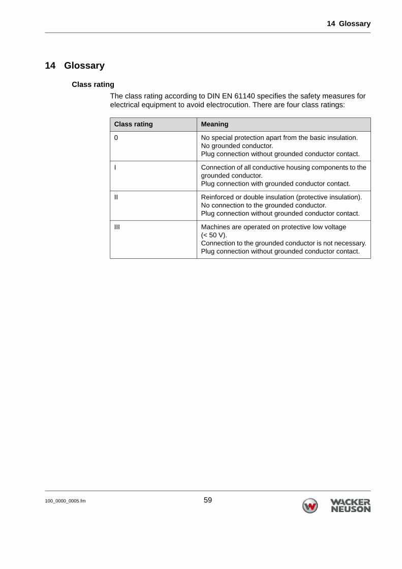
Class rating
The class rating according to DIN EN 61140 specifies the safety measures for electrical equipment to avoid electrocution. There are four class ratings:
Class rating Meaning
0 No special protection apart from the basic insulation.No grounded conductor.Plug connection without grounded conductor contact.
I Connection of all conductive housing components to the grounded conductor. Plug connection with grounded conductor contact.
II Reinforced or double insulation (protective insulation).No connection to the grounded conductor. Plug connection without grounded conductor contact.
III Machines are operated on protective low voltage (< 50 V).Connection to the grounded conductor is not necessary. Plug connection without grounded conductor contact.
14 Glossary
60 100_0000_0005.fm
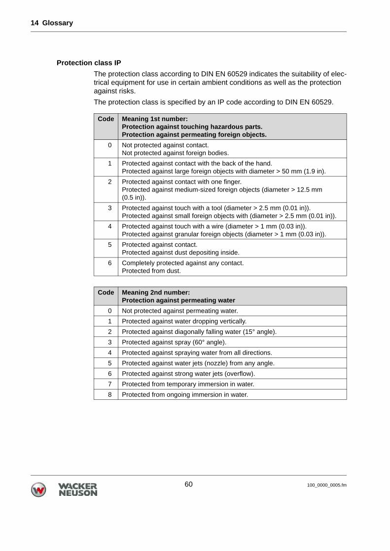
Protection class IP
The protection class according to DIN EN 60529 indicates the suitability of elec-trical equipment for use in certain ambient conditions as well as the protection against risks.
The protection class is specified by an IP code according to DIN EN 60529.
Code Meaning 1st number:Protection against touching hazardous parts.Protection against permeating foreign objects.
0 Not protected against contact.Not protected against foreign bodies.
1 Protected against contact with the back of the hand.Protected against large foreign objects with diameter > 50 mm (1.9 in).
2 Protected against contact with one finger.Protected against medium-sized foreign objects (diameter > 12.5 mm (0.5 in)).
3 Protected against touch with a tool (diameter > 2.5 mm (0.01 in)).Protected against small foreign objects with (diameter > 2.5 mm (0.01 in)).
4 Protected against touch with a wire (diameter > 1 mm (0.03 in)).Protected against granular foreign objects (diameter > 1 mm (0.03 in)).
5 Protected against contact.Protected against dust depositing inside.
6 Completely protected against any contact.Protected from dust.
Code Meaning 2nd number: Protection against permeating water
0 Not protected against permeating water.
1 Protected against water dropping vertically.
2 Protected against diagonally falling water (15° angle).
3 Protected against spray (60° angle).
4 Protected against spraying water from all directions.
5 Protected against water jets (nozzle) from any angle.
6 Protected against strong water jets (overflow).
7 Protected from temporary immersion in water.
8 Protected from ongoing immersion in water.
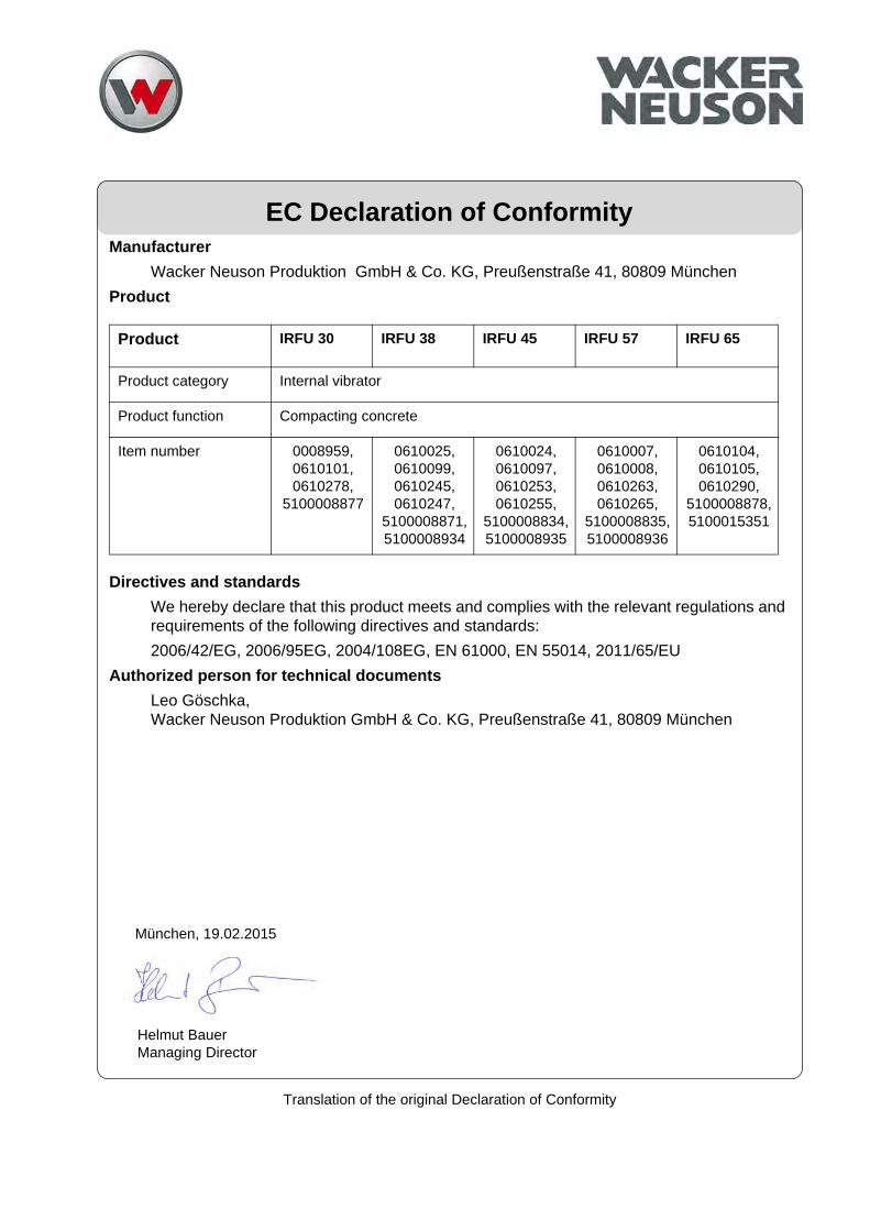
Translation of the original Declaration of Conformity
EC Declaration of ConformityManufacturer
Wacker Neuson Produktion GmbH & Co. KG, Preußenstraße 41, 80809 München
Product
Directives and standards
We hereby declare that this product meets and complies with the relevant regulations and requirements of the following directives and standards:
2006/42/EG, 2006/95EG, 2004/108EG, EN 61000, EN 55014, 2011/65/EU
Authorized person for technical documents
Leo Göschka,Wacker Neuson Produktion GmbH & Co. KG, Preußenstraße 41, 80809 München
Product IRFU 30 IRFU 38 IRFU 45 IRFU 57 IRFU 65
Product category Internal vibrator
Product function Compacting concrete
Item number 0008959, 0610101, 0610278,
5100008877
0610025, 0610099, 0610245, 0610247,
5100008871,5100008934
0610024, 0610097, 0610253, 0610255,
5100008834, 5100008935
0610007, 0610008, 0610263, 0610265,
5100008835, 5100008936
0610104, 0610105, 0610290,
5100008878, 5100015351
Helmut BauerManaging Director
München, 19.02.2015
