operator’s manual idealarc ac1200 - askaynak · pdf fileidealarc ® ac1200...
TRANSCRIPT

IDEALARC ® AC1200
Operator’s Manual
Save for future reference
Date Purchased
Code: (ex: 10859)
Serial: (ex: U1060512345)
IM10119 | Issue D ate 12-Oct
© Lincoln Global, Inc. All Rights Reserved.
For use with machines having Code Numbers:
11869
Register your machine: www.lincolnelectric.com/register
Authorized Service and Distributor Locator: www.lincolnelectric.com/locator

FOR ENGINEpowered equipment.
1.a. Turn the engine off before troubleshooting and maintenancework unless the maintenance work requires it to be running.
____________________________________________________1.b. Operate engines in open, well-ventilated
areas or vent the engine exhaust fumes outdoors.
____________________________________________________1.c. Do not add the fuel near an open flame
welding arc or when the engine is running.Stop the engine and allow it to cool beforerefueling to prevent spilled fuel from vaporiz-ing on contact with hot engine parts andigniting. Do not spill fuel when filling tank. Iffuel is spilled, wipe it up and do not startengine until fumes have been eliminated.
____________________________________________________1.d. Keep all equipment safety guards, covers and devices in
position and in good repair.Keep hands, hair, clothing andtools away from V-belts, gears, fans and all other movingparts when starting, operating or repairing equipment.
____________________________________________________
1.e. In some cases it may be necessary to remove safetyguards to perform required maintenance. Removeguards only when necessary and replace them when themaintenance requiring their removal is complete.Always use the greatest care when working near movingparts.
___________________________________________________1.f. Do not put your hands near the engine fan.
Do not attempt to override the governor oridler by pushing on the throttle control rodswhile the engine is running.
___________________________________________________1.g. To prevent accidentally starting gasoline engines while
turning the engine or welding generator during maintenancework, disconnect the spark plug wires, distributor cap ormagneto wire as appropriate.
iSAFETYi
ARC WELDING CAN BE HAZARDOUS. PROTECT YOURSELF AND OTHERS FROM POSSIBLE SERIOUS INJURY OR DEATH.KEEP CHILDREN AWAY. PACEMAKER WEARERS SHOULD CONSULT WITH THEIR DOCTOR BEFORE OPERATING.
Read and understand the following safety highlights. For additional safety information, it is strongly recommended that youpurchase a copy of “Safety in Welding & Cutting - ANSI Standard Z49.1” from the American Welding Society, P.O. Box351040, Miami, Florida 33135 or CSA Standard W117.2-1974. A Free copy of “Arc Welding Safety” booklet E205 is availablefrom the Lincoln Electric Company, 22801 St. Clair Avenue, Cleveland, Ohio 44117-1199.
BE SURE THAT ALL INSTALLATION, OPERATION, MAINTENANCE AND REPAIR PROCEDURES AREPERFORMED ONLY BY QUALIFIED INDIVIDUALS.
WARNING
ELECTRIC AND MAGNETIC FIELDSmay be dangerous
2.a. Electric current flowing through any conductor causes localized Electric and Magnetic Fields (EMF). Welding current creates EMF fields around welding cables and welding machines
2.b. EMF fields may interfere with some pacemakers, andwelders having a pacemaker should consult their physicianbefore welding.
2.c. Exposure to EMF fields in welding may have other healtheffects which are now not known.
2.d. All welders should use the following procedures in order tominimize exposure to EMF fields from the welding circuit:
2.d.1. Route the electrode and work cables together - Securethem with tape when possible.
2.d.2. Never coil the electrode lead around your body.
2.d.3. Do not place your body between the electrode andwork cables. If the electrode cable is on your right side, the work cable should also be on your right side.
2.d.4. Connect the work cable to the workpiece as close aspossible to the area being welded.
2.d.5. Do not work next to welding power source.
1.h. To avoid scalding, do not remove theradiator pressure cap when the engine ishot.
CALIFORNIA PROPOSITION 65 WARNINGS
Diesel engine exhaust and some of its constituentsare known to the State of California to cause can-cer, birth defects, and other reproductive harm.
The engine exhaust from this product containschemicals known to the State of California to causecancer, birth defects, or other reproductive harm.
The Above For Diesel Engines The Above For Gasoline Engines
ARC RAYS can burn.4.a. Use a shield with the proper filter and cover
plates to protect your eyes from sparks andthe rays of the arc when welding or observingopen arc welding. Headshield and filter lensshould conform to ANSI Z87. I standards.
4.b. Use suitable clothing made from durable flame-resistantmaterial to protect your skin and that of your helpers fromthe arc rays.
4.c. Protect other nearby personnel with suitable, non-flammablescreening and/or warn them not to watch the arc nor exposethemselves to the arc rays or to hot spatter or metal.
ELECTRIC SHOCK cankill.3.a. The electrode and work (or ground) circuits
are electrically “hot” when the welder is on.Do not touch these “hot” parts with your bareskin or wet clothing. Wear dry, hole-free
gloves to insulate hands.
3.b. Insulate yourself from work and ground using dry insulation.Make certain the insulation is large enough to cover your fullarea of physical contact with work and ground.
In addition to the normal safety precautions, if weldingmust be performed under electrically hazardousconditions (in damp locations or while wearing wetclothing; on metal structures such as floors, gratings orscaffolds; when in cramped positions such as sitting,kneeling or lying, if there is a high risk of unavoidable oraccidental contact with the workpiece or ground) usethe following equipment:
• Semiautomatic DC Constant Voltage (Wire) Welder.• DC Manual (Stick) Welder.• AC Welder with Reduced Voltage Control.
3.c. In semiautomatic or automatic wire welding, the electrode,electrode reel, welding head, nozzle or semiautomaticwelding gun are also electrically “hot”.
3.d. Always be sure the work cable makes a good electricalconnection with the metal being welded. The connectionshould be as close as possible to the area being welded.
3.e. Ground the work or metal to be welded to a good electrical(earth) ground.
3.f. Maintain the electrode holder, work clamp, welding cable andwelding machine in good, safe operating condition. Replacedamaged insulation.
3.g. Never dip the electrode in water for cooling.
3.h. Never simultaneously touch electrically “hot” parts ofelectrode holders connected to two welders because voltagebetween the two can be the total of the open circuit voltageof both welders.
3.i. When working above floor level, use a safety belt to protectyourself from a fall should you get a shock.
3.j. Also see Items 6.c. and 8.
iiSAFETYii
FUMES AND GASEScan be dangerous.5.a. Welding may produce fumes and gases
hazardous to health. Avoid breathing thesefumes and gases. When welding, keepyour head out of the fume. Use enoughventilation and/or exhaust at the arc to keep
fumes and gases away from the breathing zone. Whenwelding with electrodes which require specialventilation such as stainless or hard facing (seeinstructions on container or MSDS) or on lead orcadmium plated steel and other metals or coatingswhich produce highly toxic fumes, keep exposure aslow as possible and within applicable OSHA PEL and ACGIH TLV limits using local exhaust or mechanicalventilation. In confined spaces or in some circum-stances, outdoors, a respirator may be required.Additional precautions are also required when weldingon galvanized steel.
5. b. The operation of welding fume control equipment is affectedby various factors including proper use and positioning ofthe equipment, maintenance of the equipment and the spe-cific welding procedure and application involved. Workerexposure level should be checked upon installation andperiodically thereafter to be certain it is within applicableOSHA PEL and ACGIH TLV limits.
5.c. Do not weld in locations near chlorinated hydrocarbon vaporscoming from degreasing, cleaning or spraying operations.The heat and rays of the arc can react with solvent vapors toform phosgene, a highly toxic gas, and other irritating prod-ucts.
5.d. Shielding gases used for arc welding can displace air andcause injury or death. Always use enough ventilation,especially in confined areas, to insure breathing air is safe.
5.e. Read and understand the manufacturer’s instructions for thisequipment and the consumables to be used, including thematerial safety data sheet (MSDS) and follow youremployer’s safety practices. MSDS forms are available fromyour welding distributor or from the manufacturer.
5.f. Also see item 1.b.

FOR ELECTRICALLYpowered equipment.
8.a. Turn off input power using the disconnectswitch at the fuse box before working onthe equipment.
8.b. Install equipment in accordance with the U.S. NationalElectrical Code, all local codes and the manufacturer’srecommendations.
8.c. Ground the equipment in accordance with the U.S. NationalElectrical Code and the manufacturer’s recommendations.
CYLINDER may explodeif damaged.7.a. Use only compressed gas cylinders
containing the correct shielding gas for theprocess used and properly operatingregulators designed for the gas and
pressure used. All hoses, fittings, etc. should be suitable forthe application and maintained in good condition.
7.b. Always keep cylinders in an upright position securelychained to an undercarriage or fixed support.
7.c. Cylinders should be located:• Away from areas where they may be struck or subjected tophysical damage.
• A safe distance from arc welding or cutting operations andany other source of heat, sparks, or flame.
7.d. Never allow the electrode, electrode holder or any otherelectrically “hot” parts to touch a cylinder.
7.e. Keep your head and face away from the cylinder valve outletwhen opening the cylinder valve.
7.f. Valve protection caps should always be in place and handtight except when the cylinder is in use or connected foruse.
7.g. Read and follow the instructions on compressed gascylinders, associated equipment, and CGA publication P-l,“Precautions for Safe Handling of Compressed Gases inCylinders,” available from the Compressed Gas Association1235 Jefferson Davis Highway, Arlington, VA 22202.
WELDING and CUTTINGSPARKS cancause fire or explosion.6.a. Remove fire hazards from the welding area.
If this is not possible, cover them to preventthe welding sparks from starting a fire.
Remember that welding sparks and hotmaterials from welding can easily go through small cracksand openings to adjacent areas. Avoid welding nearhydraulic lines. Have a fire extinguisher readily available.
6.b. Where compressed gases are to be used at the job site,special precautions should be used to prevent hazardoussituations. Refer to “Safety in Welding and Cutting” (ANSIStandard Z49.1) and the operating information for theequipment being used.
6.c. When not welding, make certain no part of the electrodecircuit is touching the work or ground. Accidental contactcan cause overheating and create a fire hazard.
6.d. Do not heat, cut or weld tanks, drums or containers until theproper steps have been taken to insure that such procedureswill not cause flammable or toxic vapors from substancesinside. They can cause an explosion even though they havebeen “cleaned”. For information, purchase “RecommendedSafe Practices for the Preparation for Welding and Cutting ofContainers and Piping That Have Held HazardousSubstances”, AWS F4.1 from the American Welding Society(see address above).
6.e. Vent hollow castings or containers before heating, cutting orwelding. They may explode.
6.f. Sparks and spatter are thrown from the welding arc. Wear oilfree protective garments such as leather gloves, heavy shirt,cuffless trousers, high shoes and a cap over your hair. Wearear plugs when welding out of position or in confined places.Always wear safety glasses with side shields when in awelding area.
6.g. Connect the work cable to the work as close to the weldingarea as practical. Work cables connected to the buildingframework or other locations away from the welding areaincrease the possibility of the welding current passingthrough lifting chains, crane cables or other alternate cir-cuits. This can create fire hazards or overheat lifting chainsor cables until they fail.
6.h. Also see item 1.c.
6.I. Read and follow NFPA 51B “ Standard for Fire PreventionDuring Welding, Cutting and Other Hot Work”, availablefrom NFPA, 1 Batterymarch Park, PO box 9101, Quincy, Ma022690-9101.
6.j. Do not use a welding power source for pipe thawing.
iiiSAFETYiii
Refer to http://www.lincolnelectric.com/safety for additional safety information.

ivSAFETYiv
PRÉCAUTIONS DE SÛRETÉPour votre propre protection lire et observer toutes les instructionset les précautions de sûreté specifiques qui parraissent dans cemanuel aussi bien que les précautions de sûreté générales suiv-antes:
Sûreté Pour Soudage A LʼArc1. Protegez-vous contre la secousse électrique:
a. Les circuits à lʼélectrode et à la piéce sont sous tensionquand la machine à souder est en marche. Eviter toujourstout contact entre les parties sous tension et la peau nueou les vétements mouillés. Porter des gants secs et sanstrous pour isoler les mains.
b. Faire trés attention de bien sʼisoler de la masse quand onsoude dans des endroits humides, ou sur un planchermetallique ou des grilles metalliques, principalement dans les positions assis ou couché pour lesquelles une grandepartie du corps peut être en contact avec la masse.
c. Maintenir le porte-électrode, la pince de masse, le câblede soudage et la machine à souder en bon et sûr étatdefonctionnement.
d.Ne jamais plonger le porte-électrode dans lʼeau pour lerefroidir.
e. Ne jamais toucher simultanément les parties sous tensiondes porte-électrodes connectés à deux machines à souderparce que la tension entre les deux pinces peut être letotal de la tension à vide des deux machines.
f. Si on utilise la machine à souder comme une source decourant pour soudage semi-automatique, ces precautionspour le porte-électrode sʼapplicuent aussi au pistolet desoudage.
2. Dans le cas de travail au dessus du niveau du sol, se protégercontre les chutes dans le cas ou on recoit un choc. Ne jamaisenrouler le câble-électrode autour de nʼimporte quelle partiedu corps.
3. Un coup dʼarc peut être plus sévère quʼun coup de soliel,donc:
a. Utiliser un bon masque avec un verre filtrant appropriéainsi quʼun verre blanc afin de se protéger les yeux du ray-onnement de lʼarc et des projections quand on soude ouquand on regarde lʼarc.
b. Porter des vêtements convenables afin de protéger lapeau de soudeur et des aides contre le rayonnement delʻarc.
c. Protéger lʼautre personnel travaillant à proximité ausoudage à lʼaide dʼécrans appropriés et non-inflammables.
4. Des gouttes de laitier en fusion sont émises de lʼarc desoudage. Se protéger avec des vêtements de protection libresde lʼhuile, tels que les gants en cuir, chemise épaisse, pan-talons sans revers, et chaussures montantes.
5. Toujours porter des lunettes de sécurité dans la zone desoudage. Utiliser des lunettes avec écrans lateraux dans leszones où lʼon pique le laitier.
6. Eloigner les matériaux inflammables ou les recouvrir afin deprévenir tout risque dʼincendie dû aux étincelles.
7. Quand on ne soude pas, poser la pince à une endroit isolé dela masse. Un court-circuit accidental peut provoquer unéchauffement et un risque dʼincendie.
8. Sʼassurer que la masse est connectée le plus prés possiblede la zone de travail quʼil est pratique de le faire. Si on placela masse sur la charpente de la construction ou dʼautresendroits éloignés de la zone de travail, on augmente le risquede voir passer le courant de soudage par les chaines de lev-age, câbles de grue, ou autres circuits. Cela peut provoquerdes risques dʼincendie ou dʼechauffement des chaines et descâbles jusquʼà ce quʼils se rompent.
9. Assurer une ventilation suffisante dans la zone de soudage.Ceci est particuliérement important pour le soudage de tôlesgalvanisées plombées, ou cadmiées ou tout autre métal quiproduit des fumeés toxiques.
10. Ne pas souder en présence de vapeurs de chlore provenantdʼopérations de dégraissage, nettoyage ou pistolage. Lachaleur ou les rayons de lʼarc peuvent réagir avec les vapeursdu solvant pour produire du phosgéne (gas fortement toxique)ou autres produits irritants.
11. Pour obtenir de plus amples renseignements sur la sûreté,voir le code “Code for safety in welding and cutting” CSAStandard W 117.2-1974.
PRÉCAUTIONS DE SÛRETÉ POURLES MACHINES À SOUDER ÀTRANSFORMATEUR ET ÀREDRESSEUR
1. Relier à la terre le chassis du poste conformement au code delʼélectricité et aux recommendations du fabricant. Le dispositifde montage ou la piece à souder doit être branché à unebonne mise à la terre.
2. Autant que possible, Iʼinstallation et lʼentretien du poste seronteffectués par un électricien qualifié.
3. Avant de faires des travaux à lʼinterieur de poste, la debranch-er à lʼinterrupteur à la boite de fusibles.
4. Garder tous les couvercles et dispositifs de sûreté à leurplace.

vv
Thank You for selecting a QUALITY product by Lincoln Electric. We want youto take pride in operating this Lincoln Electric Company product••• as much pride as we have in bringing this product to you!
Read this Operators Manual completely before attempting to use this equipment. Save this manual and keep ithandy for quick reference. Pay particular attention to the safety instructions we have provided for your protection.The level of seriousness to be applied to each is explained below:
WARNINGThis statement appears where the information must be followed exactly to avoid serious personal injury or loss of life.
This statement appears where the information must be followed to avoid minor personal injury or damage to this equipment.
CAUTION
Please Examine Carton and Equipment For Damage ImmediatelyWhen this equipment is shipped, title passes to the purchaser upon receipt by the carrier. Consequently, Claimsfor material damaged in shipment must be made by the purchaser against the transportation company at thetime the shipment is received.
Please record your equipment identification information below for future reference. This information can befound on your machine nameplate.
Product _________________________________________________________________________________
Model Number ___________________________________________________________________________
Code Number or Date Code_________________________________________________________________
Serial Number____________________________________________________________________________
Date Purchased___________________________________________________________________________
Where Purchased_________________________________________________________________________
Whenever you request replacement parts or information on this equipment, always supply the information youhave recorded above. The code number is especially important when identifying the correct replacement parts.
On-Line Product Registration- Register your machine with Lincoln Electric either via fax or over the Internet.• For faxing: Complete the form on the back of the warranty statement included in the literature packet
accompanying this machine and fax the form per the instructions printed on it.• For On-Line Registration: Go to our WEB SITE at www.lincolnelectric.com. Choose “Support” and then “Register
Your Product”. Please complete the form and submit your registration.
CUSTOMER ASSISTANCE POLICYThe business of The Lincoln Electric Company is manufacturing and selling high quality welding equipment, consumables, and cutting equip-ment. Our challenge is to meet the needs of our customers and to exceed their expectations. On occasion, purchasers may ask LincolnElectric for advice or information about their use of our products. We respond to our customers based on the best information in our posses-sion at that time. Lincoln Electric is not in a position to warrant or guarantee such advice, and assumes no liability, with respect to such infor-mation or advice. We expressly disclaim any warranty of any kind, including any warranty of fitness for any customer’s particular purpose,with respect to such information or advice. As a matter of practical consideration, we also cannot assume any responsibility for updating orcorrecting any such information or advice once it has been given, nor does the provision of information or advice create, expand or alter anywarranty with respect to the sale of our products.
Lincoln Electric is a responsive manufacturer, but the selection and use of specific products sold by Lincoln Electric is solely within the controlof, and remains the sole responsibility of the customer. Many variables beyond the control of Lincoln Electric affect the results obtained inapplying these types of fabrication methods and service requirements.
Subject to Change – This information is accurate to the best of our knowledge at the time of printing. Please refer to www.lincolnelectric.comfor any updated information.

Page
Installation .......................................................................................................Section ATechnical Specifications ........................................................................................A-1Location ................................................................................................................A-2Input Wiring............................................................................................................A-2Output Connections...............................................................................................A-2
1. Wire Feeder Connections ...........................................................................A-2Connection of AC-1200 (with NL Option) to LAF or LT34 .....................................A-3Connection of AC-1200 to NA-4 with Switch for ʻCurrent Controlʼ.........................A-3Connection of AC-1200 to NA-4 with rheostat for current control or LT-6. ............A-3
2. Output Studs ...............................................................................................A-43. Auxiliary Power ...........................................................................................A-4
Duty Cycle .............................................................................................................A-4
_______________________________________________________________________
Operation .........................................................................................................Section BSafety Precautions.................................................................................................B-1To set for machine or Remote Control...................................................................B-1To set Output Current ............................................................................................B-1
________________________________________________________________________
Accessories .....................................................................................................Section COptional Kit ............................................................................................................C-1
________________________________________________________________________
Maintenance ....................................................................................................Section DSafety Precautions ................................................................................................D-1
________________________________________________________________________
Troubleshooting ..............................................................................................Section ESafety Precautions.................................................................................................E-1How to Use Troubleshooting Guide.......................................................................E-1Troubleshooting Guide....................................................................................E-2,E-3
________________________________________________________________________
Wiring Diagram and Connection Diagrams .................................................Section F________________________________________________________________________
Parts Pages............................................................................................... P-701, P-28-J________________________________________________________________________
vi vi TABLE OF CONTENTS

A-1INSTALLATION
IDEALARC® AC-1200
A-1
Weight1636 lbs.(742 kg.)
INPUT - SINGLE PHASE ONLY
RATED OUTPUT
PHYSICAL DIMENSIONS
RECOMMENDED INPUT WIRE GROUNDING CONDUCTOR AND FUSE SIZES
Standard Voltage
Duty Cycle100%
Current Range240/1200
Maximum Open Circuit Voltage
Depth38.00 in.
(965.2mm.)
Width22.30 in.
(566.4mm.)
Height53.50 in.
( 1358.9mm.)
AMPS AC1200 @ 44 Volts
Input Current at 100% Rated OutputSingle Phase Output Scott Connection
460/60440/50/60415/50/60380/50/60
182 209190 219201 232220 255
TECHNICAL SPECIFICATIONS - IDEALARC® AC-1200
86-88
RATING: IP21 ENCLOSURE
Power Factor @ Rated load With P.F. Capacitors
79%(60 Hz) 76%(50 Hz)
Input Copper Wire Size - 75˚C in Conduit Super Lag FusesVoltage/ Input Amps Power Input Wires Grounding Conductor Size in Amps
Hertz1 Phase Scott 1 Phase Scott 1 Phase Scott 1 Phase Scott
Conn. Conn. Conn. Conn.
460/60 182 209 #4/0 250MCM #4 #3 300 350
440/50/60 190 219 #4/0 250MCM #4 #3 300 350
415/50/60 201 232 #4/0 300MCM #4 #3 300 350
380/50/60 220 255 250MCM 350MCM #3 #3 300 400

A-2INSTALLATION
IDEALARC® AC-1200
A-2
LOCATIONInstall the welder in a dry location where there is freecirculation of air in through the louvers in front and outthrough the louvers in the back of the case. A locationwhich minimizes the amount of smoke and dirt drawninto the machine reduces the chance of dirt accumula-tion that can block air passages and cause overheat-ing.
INPUT WIRING
Failure to fuse the input lines per the specificationsin this manual will constitute customer abuse andvoid the warranty.-----------------------------------------------------------------------------Have a qualified electrician make the complete inputconnection in accordance with the National ElectricalCode, all local codes and the connection diagramlocated inside the machine.
Be sure the voltage, phase and frequency of the inputpower is as specified on the welder nameplate.
For most installations, connect the AC-1200 to singlephase power or to one phase of a three phase line.Unbalanced line conditions can be easily avoided byproperly balancing the AC-1200 with other machineryon the lines.
When installing two or four Scott connected AC-1200machines for AC-AC tandem arc welding, three phaseinput power must be used. The terminals for connec-tions to provide an output phase angle less than orgreater than the usual 90º phase angle are includedon the input panel.
The AC-1200 does not have an input contactor.Therefore, include an external starter or disconnectswitch when planning the input circuit.
Remove the right side panel of the AC-1200 and bring theinput power lines through the hole in the back of the case.See the table below for reccomended sizing of input leadsand overcurrent protection.
The frame of the welder must be grounded, A stud markedwith the symbol located on the welder case backhole in the back of the case is provided for this purpose.See the National Electrical Code for details on propergrounding methods.
OUTPUT CONNECTIONS
1. Wire Feeder Connection
Turn the input power to the welder off. Remove thescrew and lift the hinged door on the front of the controlpanel to expose the terminal strips. Connect the leads ofthe wire feeder input control cable to the terminal stripsexactly as specified in the appropriate connection diagram.The AC-1200 to NA-4 connection diagrams are includedin the NA-4 Operating Manual IM-278. Attach the controlcables to the panel at the right of the terminal strip usingthe clamps provided.
If connecting the AC-1200 to an older NA-4 with the tog-gle switch type “Current Control” (below code 7532), a K-775 “Remote Control” must be purchased and installed inaccordance with the connection diagram S-15667 on page5. The “Remote Control” cord can be lengthened to anylength by properly splicing a four conductor cord to thestandard 25ʼ cord before connecting to the AC-1200 ter-minal strip.
If connecting the AC-1200 to an LAF-4 or the AC con-trols of the LT-34 tractor, the AC-1200 must be orderedwith the required “–NL” optional circuit installed. This kitincludes the K-775 “Remote Control”. Connect in accor-dance with diagram S-15666 on page 5.
To connect the AC-1200 to any other wire feeder, write tothe factory for instructions giving complete nameplate infor-mation for the specific equipment.
When connection to the terminal strips are completed,close the door and replace the screw.
WARNING
ELECTRIC SHOCKcan kill.
• Have an electrician installand service this equip-ment.
• Turn the input power off atthe fuse box before work-ing on equipment.
• Do not touch electricallyhot parts.

A-3INSTALLATION
IDEALARC® AC-1200
A-3
Connection of AC-1200 (with NL Option) S-15666to LAF-4 or LT-34 4-18-75
Connection of AC-1200 to NA-4 S-15667
with Switch for ‘Current Control’ 4-18-75
Connection of AC-1200 toNA-4 with rheostat for current control or LT-6.
S-15602
6-22-84H

A-4INSTALLATION
IDEALARC® AC-1200
A-4
2. Output Studs
Connect the work cables to the “To Work” stud onthe front of the AC-1200. Connect the electrodecables to the “Min”, “Med” or “Max” studs for theoutput desired. Actual current ranges for each studare indicated on the nameplate above each stud.Recommended cable sizes are listed below. Boththe “To Work” and “Max” studs have two terminalsto simplify connection of recommended cables inparallel. Tighten the nuts with a wrench.
Select cables required for combined work and elec-trode cable lengths up to 150ʼ from the followingtable:
Maximum Allowable Current for Copper Welding CableCables in accessory kit recommended below haveterminals as required to comply with applicableU.L. standards for safety.
150ʼ combined length electrode and work cables.
3. Auxiliary Power
920 volt-amperes of 115 volt AC power are avail-able from #31 and #32 on the AC-1200 terminalstrip.
DUTY CYCLE
The AC-1200 is rated for 100% duty cycle at 1200amps and 44 volts.
DutyCycle One 4/0 Two 4/0 Three 4/0 Four 4/0100% 500 930 1150 135080%* 560 1040 1290 1510
* Based on 10 minute cycle.

B-1OPERATION
IDEALARC® AC-1200
B-1
TO SET FOR LOCAL OR REMOTECONTROLThe output can be controlled either from the AC-1200, the wire feeder or other remote locations.
To adjust the current from the wire feeder or otherremote locations, set the toggle switch on the front ofthe AC-1200 to “ “. To adjust the output currentfrom the AC-1200, set this switch to “ “.
T0 SET THE OUTPUT CURRENT
Start the AC-1200 using the line disconnect switch orbreaker installed with the input wiring. The yellow pilotlight on the front panel indicates when the welder ison.
Adjust the output current from minimum to maximumwithin the range set by the output stud connectionsusing either the “ “ rheostat on the AC-1200 (tog-gle switch set on “ “) or the wire feeder or otherremote rheostat (toggle switch set on “ “).
ELECTRIC SHOCKcan kill.
• Do not touch electrically live partsor electrode with skin or wetclothing.
• Insulate yourself from work andground.
• Always wear dry insulating gloves.
FUMES AND GASEScan be dangerous.
• Keep your head out of fumes.
• Use ventilation or exhaust toremove fumes from breathingzone.
WELDING SPARKScan cause fire orexplosion
• Keep flammable material away.
• Do not weld on containers thathave held combustibles.
ARC RAYScan burn.
• Wear eye, ear and bodyprotection.
SAFETY PRECAUTIONS
Read and understand this entire section before oper-ating the machine.
Observe additional Safety Guidelines detailedthroughout this manual.
WARNING
GRAPHIC SYMBOLS THAT APPEAR ONTHIS MACHINE OR IN THIS MANUAL
Output Control 1 Single Phase
Remote Control Setting 3 Three Phase
Local Control Settin Uo Rated No-Load Voltage
Input Power Type U1 Rated Input Voltage
Submerged Arc Welding U2 Rated Welding Voltage
Transformer Type X Rated Duty Cycle
Fuse I1 Rated Input Current
High Voltage Indicator I2 Rated Welding Current
High Temperature Indicator
Rated Frequency

C-1ACCESSORIESC-1
OPTIONAL KIT: Remote control K775.
IDEALARC® AC-1200

D-1MAINTENANCED-1
IDEALARC® AC-1200
SAFETY PRECAUTIONS
ELECTRIC SHOCK can kill.• Have qualified personnel do the
maintenance and troubleshootingwork.
• Turn the input power OFF at the disconnectswitch or fuse box before working on thisequipment.
• Do not touch electrically live parts or electrodewith skin or wet clothing.
• Insulate yourself from work and ground.
• Always wear dry insulating gloves.------------------------------------------------------------------------See additional warning informationthroughout this operatorʼs manual.
------------------------------------------------------------
1. Every three months, blow out the machine withcompressed air. More frequent cleaning may benecessary in areas with chemical or metallic parti-cles and large quantities of dust.
2. The fan motors have sealed bearings which requireno service.
WARNING

E-1TROUBLESHOOTINGE-1
IDEALARC® AC-1200
If for any reason you do not understand the test procedures or are unable to perform the tests/repairs safely, contact yourLocal Lincoln Authorized Field Service Facility for technical troubleshooting assistance before you proceed.
CAUTION
This Troubleshooting Guide is provided to help youlocate and repair possible machine malfunctions.Simply follow the three-step procedure listed below.
Step 1. LOCATE PROBLEM (SYMPTOM).Look under the column labeled “PROBLEM (SYMP-TOMS)”. This column describes possible symptomsthat the machine may exhibit. Find the listing thatbest describes the symptom that the machine isexhibiting.
Step 2. POSSIBLE CAUSE.The second column labeled “POSSIBLE CAUSE” liststhe obvious external possibilities that may contributeto the machine symptom.
Step 3. RECOMMENDED COURSE OF ACTIONThis column provides a course of action for thePossible Cause, generally it states to contact yourlocal Lincoln Authorized Field Service Facility.
If you do not understand or are unable to perform theRecommended Course of Action safely, contact yourlocal Lincoln Authorized Field Service Facility.
HOW TO USE TROUBLESHOOTING GUIDE
Service and Repair should only be performed by Lincoln Electric Factory Trained Personnel.Unauthorized repairs performed on this equipment may result in danger to the technician andmachine operator and will invalidate your factory warranty. For your safety and to avoid ElectricalShock, please observe all safety notes and precautions detailed throughout this manual.
__________________________________________________________________________
WARNING

E-2TROUBLESHOOTINGE-2
IDEALARC® AC-1200
Observe all Safety Guidelines detailed throughout this manual
If for any reason you do not understand the test procedures or are unable to perform the tests/repairs safely, contact yourLocal Lincoln Authorized Field Service Facility for technical troubleshooting assistance before you proceed.
CAUTION
PROBLEMS(SYMPTOMS)
POSSIBLE CAUSE
RECOMMENDEDCOURSE OF ACTION
Welder will not start.
Welder will not weld (Contactorsoperating properly)
Welder will not weld (Contactors notoperating).
Welder welds at min. only no control.
1. Supply line fuse blown.
2. Open supply line lead.
3. Wrong supply line voltage.
1. Electrode or ground cable loose orbroken.
1. Thermostat on coil tripped. Welderoverheated (Fan motors operat-ing). light is on.
2. Thermal protection in auxiliarytransformer, T2, has opened. (Fanmotors not running)
3. Circuit across #2 and #4 not work-ing properly.
4. Wire feeder control power; Novoltage across #31 and #32.
1. Remote control switch in wrongposition.
2. Control rheostat open.
3. Control circuit open.
4. Open saturable reactor control coilor connection.
5. Welder control circuit dead: Novoltage across Control BoardTransformer X1-X2.
1. Replace fuse.
2. Look for possible cause andrepair.
3. Repair. Provide nameplate specifiedvoltage.
1. Tighten connection or repair bro-ken cable.
1. Check operation of fans and makesure there is no obstruction to airflow. Do not operate in excess ofwelder rating.
First check 8 Amp fuse and replace ifnecessary. If all recommendedpossible areas of misadjustmenthave been checked and the prob-lem persists, Contact your localLincoln Authorized FieldService Facility.
1. Switch to “ “ for welder rheo-stat control and to “ ” for con-trol through accessory.
If al l recommended possibleareas of misadjustment havebeen checked and the problempersists, Contact your localLincoln Authorized FieldService Facility.

E-3TROUBLESHOOTINGE-3
IDEALARC® AC-1200
If for any reason you do not understand the test procedures or are unable to perform the tests/repairs safely, contact yourLocal Lincoln Authorized Field Service Facility for technical troubleshooting assistance before you proceed.
CAUTION
PROBLEMS(SYMPTOMS)
POSSIBLE CAUSE
RECOMMENDEDCOURSE OF ACTION
Welder welds at max. only no con-trol.
Contacts chatter.
Diodes or SCR ʼs on heat sinkassemblies shorted.
Shorted or grounded current controllrheostat.
Output By-Pass Capacitors open ordisconnected.
Free wheeling diode open or discon-nected.
P.C. board components failed.
1. Low supply line voltage. Checkwith Power Company.
Faulty contactor.
If all recommended possible areasof misadjustment have beenchecked and the problem persists,Contact your local LincolnAuthorized Field Service Facility.

F-1DIAGRAMSF-1
IDEALARC® AC-1200
NO
TE
: T
his
diag
ram
is fo
r re
fere
nce
only
. It
may
not
be
accu
rate
for
all m
achi
nes
cove
red
by th
is m
anua
l. T
he s
peci
fic d
iagr
am fo
r a
part
icul
ar c
ode
is p
aste
d in
side
the
mac
hine
on
one
of th
e en
clos
ure
pane
ls.
If th
e di
agra
m is
ille
gibl
e, w
rite
to th
e S
ervi
ce D
epar
tmen
t for
a r
epla
cem
ent.
Giv
e th
e eq
uipm
ent c
ode
num
ber.

F-2DIAGRAMSF-2
IDEALARC® AC-1200
AC-1200 SCOTT CONNECTION DIAGRAM

F-3DIAGRAMSF-3
IDEALARC® AC-1200
M10033-1A.01
100
90
80
L2
L1
L2
L1
P1
C B ATO GROUND PER NATIONAL ELECTRIC CODE.
WORK
ELECTRODE
WORK
ELECTRODE
N.B.
MAIN TRANSFORMER LEAD ARC
4/O CABLES
4/O CABLE
N.C.
TEASER TRANSFORMER TRAIL ARC
4/O CABLES
4/O CABLE
N.C.
100
90
80
L2
L1
L2
L1
P1
C B ATO GROUND PER NATIONAL ELECTRIC CODE.
WORK
ELECTRODE
WORK
ELECTRODE
N.B.
N.B.
N.B.
3 PHASE SUPPLY LINE (N.A.)
NOTES:
N.B. ELECTRODE CABLES OF PARALLELED MACHINES SHOULD BE CONNECTED TO THE SAME RANGE TAP.
N.C. NUMBER OF 4/O CABLES CONNECTED: 1 ON MIN. TAP; 2 PARALLEL ON MED. TAP; 3 PARALLEL ON MAX. TAP.
TWO PARALLEL MACHINES SCOTT CONNECTED TO TWO OTHER PARALLEL MACHINES
FOR DESIRED PHASE ANGLE, INTERCONNECT MACHINES (AS SHOWN BELOW). BOTH PHASE ANGLES MUST BE THE SAME.
N.A. TO OBTAIN NORMAL PHASE SEQUENCE AT THE WELDING ARCS, THE INPUT LINE PHASE SEQUENCE SHOULD BE A-C-B.
AC-1200 SCOTT CONNECTION DIAGRAM
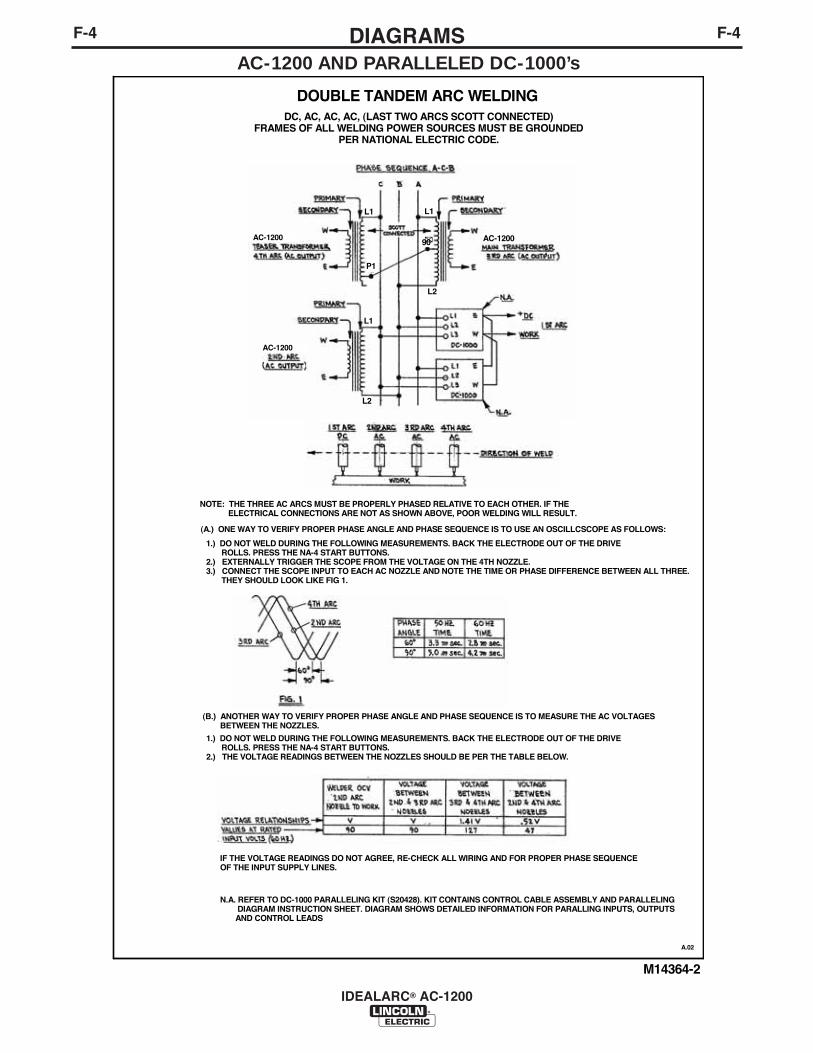
F-4DIAGRAMSF-4
IDEALARC® AC-1200
AC-1200 AND PARALLELED DC-1000’s

F-5DIAGRAMSF-5
IDEALARC® AC-1200
AC-1200 AND DC-1500’s

WARNING
AVISO DEPRECAUCION
ATTENTION
WARNUNG
ATENÇÃO
Spanish
French
German
Portuguese
Japanese
Chinese
Korean
Arabic
READ AND UNDERSTAND THE MANUFACTURER’S INSTRUCTION FOR THIS EQUIPMENT AND THE CONSUMABLES TO BEUSED AND FOLLOW YOUR EMPLOYER’S SAFETY PRACTICES.
SE RECOMIENDA LEER Y ENTENDER LAS INSTRUCCIONES DEL FABRICANTE PARA EL USO DE ESTE EQUIPO Y LOSCONSUMIBLES QUE VA A UTILIZAR, SIGA LAS MEDIDAS DE SEGURIDAD DE SU SUPERVISOR.
LISEZ ET COMPRENEZ LES INSTRUCTIONS DU FABRICANT EN CE QUI REGARDE CET EQUIPMENT ET LES PRODUITS AETRE EMPLOYES ET SUIVEZ LES PROCEDURES DE SECURITE DE VOTRE EMPLOYEUR.
LESEN SIE UND BEFOLGEN SIE DIE BETRIEBSANLEITUNG DER ANLAGE UND DEN ELEKTRODENEINSATZ DES HER-STELLERS. DIE UNFALLVERHÜTUNGSVORSCHRIFTEN DES ARBEITGEBERS SIND EBENFALLS ZU BEACHTEN.
Do not touch electrically live parts orelectrode with skin or wet clothing.Insulate yourself from work andground.
No toque las partes o los electrodosbajo carga con la piel o ropa moja-da.Aislese del trabajo y de la tierra.
Ne laissez ni la peau ni des vête-ments mouillés entrer en contactavec des pièces sous tension.Isolez-vous du travail et de la terre.
Berühren Sie keine stromführendenTeile oder Elektroden mit IhremKörper oder feuchter Kleidung!Isolieren Sie sich von denElektroden und dem Erdboden!
Não toque partes elétricas e elec-trodos com a pele ou roupa molha-da.Isole-se da peça e terra.
Keep flammable materials away.
Mantenga el material combustiblefuera del área de trabajo.
Gardez à l’écart de tout matérielinflammable.
Entfernen Sie brennbarres Material!
Mantenha inflamáveis bem guarda-dos.
Wear eye, ear and body protection.
Protéjase los ojos, los oídos y elcuerpo.
Protégez vos yeux, vos oreilles etvotre corps.
Tragen Sie Augen-, Ohren- und Kör-perschutz!
Use proteção para a vista, ouvido ecorpo.

WARNING
AVISO DEPRECAUCION
ATTENTION
WARNUNG
ATENÇÃO
Spanish
French
German
Portuguese
Japanese
Chinese
Korean
Arabic
LEIA E COMPREENDA AS INSTRUÇÕES DO FABRICANTE PARA ESTE EQUIPAMENTO E AS PARTES DE USO, E SIGA ASPRÁTICAS DE SEGURANÇA DO EMPREGADOR.
Keep your head out of fumes.Use ventilation or exhaust toremove fumes from breathing zone.
Los humos fuera de la zona de res-piración.Mantenga la cabeza fuera de loshumos. Utilice ventilación oaspiración para gases.
Gardez la tête à l’écart des fumées.Utilisez un ventilateur ou un aspira-teur pour ôter les fumées des zonesde travail.
Vermeiden Sie das Einatmen vonSchweibrauch!Sorgen Sie für gute Be- undEntlüftung des Arbeitsplatzes!
Mantenha seu rosto da fumaça.Use ventilação e exhaustão pararemover fumo da zona respiratória.
Turn power off before servicing.
Desconectar el cable de ali-mentación de poder de la máquinaantes de iniciar cualquier servicio.
Débranchez le courant avant l’entre-tien.
Strom vor Wartungsarbeitenabschalten! (Netzstrom völlig öff-nen; Maschine anhalten!)
Não opere com as tampas removidas.Desligue a corrente antes de fazerserviço.Não toque as partes elétricas nuas.
Do not operate with panel open orguards off.
No operar con panel abierto oguardas quitadas.
N’opérez pas avec les panneauxouverts ou avec les dispositifs deprotection enlevés.
Anlage nie ohne Schutzgehäuseoder Innenschutzverkleidung inBetrieb setzen!
Mantenha-se afastado das partesmoventes.Não opere com os paineis abertosou guardas removidas.

• Sales and Service through Subsidiaries and Distributors Worldwide •
Cleveland, Ohio 44117-1199 U.S.A. TEL: 216.481.8100 FAX: 216.486.1751 WEB SITE: www.lincolnelectric.com
• World's Leader in Welding and Cutting Products •