operator’s manual - home - ets company pressure …etscompany.com/pdf/landa/hot/hbg_0310.pdf ·...
TRANSCRIPT

OPERATOR’S MANUAL
WATER BLAZE SYSTEMS
® HBG■■■■■ HBG-15 ■■■■■ HBG-30
For technical assistance or the dealer nearest you consult our web page atwww.waterblaze.com or call (800-562-4993) or (360) 833-2874
LISTED ®


CONTENTS
3
HBG Manual • Form #96-6411 • Rev. 10/03
Introduction ................................................................................................................................... 5
General Safety Information......................................................................................................... 5-6
Electrical Safety Information ......................................................................................................... 6
Standard Safety Features .......................................................................................................... 6-7
Installation ................................................................................................................................. 7-9
HBG-15, HBG-30 Component Identification ................................................................................... 8
Gas Pressure Test .................................................................................................................... 9-10
Pre Start Checklist ...................................................................................................................... 10
Operating Instructions ................................................................................................................. 11
Maintenance................................................................................................................................ 12
HBG Fuel and Air Settings .......................................................................................................... 12
Auto Fill Operating Characteristics .............................................................................................. 13
Air Assisted Defoamer Operating Characteristics ........................................................................ 13
Batch Cycle Counter .............................................................................................................. 14-16
Installation Dimensions ............................................................................................................... 17
Exploded View HBG-15 .......................................................................................................... 18-19
Exploded View Parts List HBG-15 .......................................................................................... 20-21
Exploded View HBG-30 .......................................................................................................... 22-23
Exploded View Parts List HBG-30 ............................................................................................... 24
Control Panel Exploded View & Parts List ................................................................................... 25
HBG-15 Float Assembly Exploded View ...................................................................................... 26
HBG-15 Float Assembly Parts List ............................................................................................. 27
HBG-30 Float Assembly Exploded View ...................................................................................... 28
HBG-30 Float Assembly Parts List ............................................................................................. 29
HBG Auto Fill Option Exploded View ........................................................................................... 30
HBG Auto Fill Option Parts List ................................................................................................... 31
HBG Defoamer Option Exploded View ......................................................................................... 32
HBG Defoamer Option Parts List ................................................................................................ 33
HBG Oil Skimmer Option Exploded View .................................................................................... 34
HBG Oil Skimmer Option Parts List ............................................................................................ 35
Replacing Pump Head Tubing ...................................................................................................... 36
VSP20 Metering Anti-Foam Pump............................................................................................... 37
Burner Assembly HBG-30 #HSG400 & Parts List ................................................................... 38-39
Gas Train Assembly and Parts List ............................................................................................. 39

Model Number ______________________________
Serial Number ______________________________
Date of Purchase ____________________________
The model and serial numbers will be found on a decal attached tothe evaportor. You should record both serial number and date ofpurchase and keep in a safe place for future reference.
CONTENTS
4
HBG Manual • Form #96-6411 • Revised 10/03
Troubleshooting ...................................................................................................................... 40-41
HBG Cost Formulas .................................................................................................................... 42
Specifications ............................................................................................................................. 42
Preventative Maintenance ........................................................................................................... 43
Warranty ...................................................................................................................................... 44
HBG EVAPORATOR OPERATOR’S MANUAL 5
WATER BLAZE HBG • 96-6411 • REV. 10/03
WARNING
RISK OF EXPLOSION.IF YOU SMELL GAS,
SHUT OFF GASSUPPLY.
INTRODUCTIONThank you for purchasing a WATER BLAZE HBG.
This manual covers the operation and maintenance ofHBG evaporators. All information in this manual is basedon the latest product information available at time of print-ing.
WATER BLAZE reserves the right to make changes atany time without incurring any obligation.
Owner/User Responsibility:The owner and/or user must have an understanding ofthe manufacturer’s operating instructions and warningsbefore using this WATER BLAZE machine. Warning in-formation should be emphasized and understood. If theoperator is not fluent in English, the manufacturer’s in-structions and warnings shall be read to and discussedwith the operator in the operator’s native language by thepurchaser/owner, making sure that the operator compre-hends its contents.
Owner and/or user must study and maintain for futurereference the manufacturers’ instructions.
This manual should be considered a permanentpart of the machine and should remain with it ifmachine is resold.
When ordering parts, please specify model andserial number.
Please Note: WATER BLAZE is not responsible for pro-curement of regulatory and/or operating permits that maybe required by city, county, state or federal agencies. Itis the customer who is responsible for procurement ofany hazardous or non-hazardous regulatory and/or oper-ating permits, compliance with codes or other govern-mental requirements associated with the installation, use,or disposal of waste associated with this equipment. Sub-merged combustion can be classified as incineration inspecific jurisdictions. It is the customer's responsibilityfor procurement of appropriate local and state permits asneeded.
The guidelines listed in the evaporator feasibility reportare specific only to the waste stream submitted for theevaluation and estimated emissions. Moreover, WATERBLAZE is not reponsible for the operation or maintenanceof the evaporator unit. If the unit is subjected to any wastestream other than that which has been tested by thenamed laboratory, operation may cause adverse effectson the equipment and will negate any warranty of partsor equipment.
IMPORTANTSAFETY INFORMATION
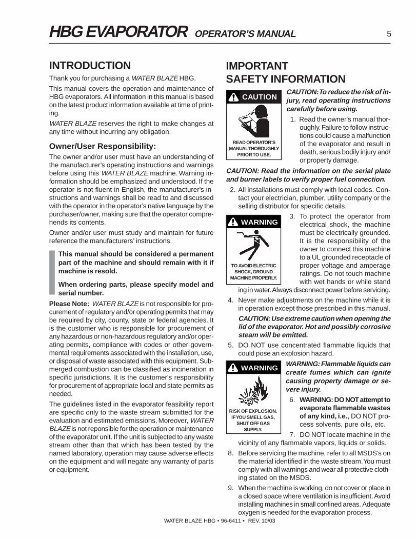
CAUTION: To reduce the risk of in-jury, read operating instructionscarefully before using. 1. Read the owner's manual thor-
oughly. Failure to follow instruc-tions could cause a malfunctionof the evaporator and result indeath, serious bodily injury and/or property damage.
CAUTION: Read the information on the serial plateand burner labels to verify proper fuel connection.
2. All installations must comply with local codes. Con-tact your electrician, plumber, utility company or theselling distributor for specific details.
3. To protect the operator fromelectrical shock, the machinemust be electrically grounded.It is the responsibility of theowner to connect this machineto a UL grounded receptacle ofproper voltage and amperageratings. Do not touch machinewith wet hands or while stand
ing in water. Always disconnect power before servicing.
4. Never make adjustments on the machine while it isin operation except those prescribed in this manual.
CAUTION: Use extreme caution when opening thelid of the evaporator. Hot and possibly corrosivesteam will be emitted.
5. DO NOT use concentrated flammable liquids thatcould pose an explosion hazard.
WARNING: Flammable liquids cancreate fumes which can ignitecausing property damage or se-vere injury. 6. WARNING: DO NOT attempt to
evaporate flammable wastesof any kind, i.e., DO NOT pro-cess solvents, pure oils, etc.
7. DO NOT locate machine in thevicinity of any flammable vapors, liquids or solids.
8. Before servicing the machine, refer to all MSDS’s onthe material identified in the waste stream. You mustcomply with all warnings and wear all protective cloth-ing stated on the MSDS.
9. When the machine is working, do not cover or place ina closed space where ventilation is insufficient. Avoidinstalling machines in small confined areas. Adequateoxygen is needed for the evaporation process.
READ OPERATOR’SMANUAL THOROUGHLY
PRIOR TO USE.
CAUTION
WARNING
TO AVOID ELECTRICSHOCK, GROUND
MACHINE PROPERLY.

6 HBG EVAPORATOR OPERATOR’S MANUAL
WATER BLAZE HBG • 96-6411 • REV. 10/03
10. The HBG and components will freeze if not in opera-tion. In cold climates locate HBG in heated enclo-sure.
11. Running the system without water damages the tankfloor and voids the warranty.
NOTE: Allow tank to cool before adding wastewateror damage will occur to tank floor due to thermalshock.
12. The HBG must be installed and training provided byan authorized dealer.
13. Do not operate the equipment in an unvented, en-closed area. Carbon monoxide may accumulate.
14. If you smell gas, shut off thegas supply valve, extinguishany open flame and test all jointswith a soap solution. If the odorpersists, call your gas supplierimmediately.
15. Only those liquid wastes thathave been approved by WATERBLAZE, and the proper regula-tory agencies, should be placed
in the HBG machine. Test methods as outlined inWATER BLAZE Profile 3518 must be obtained. NOTE:WATER BLAZE is not liable for the performance andthe warranty will be void when waste liquids that arenot tested and approved are introduced into the HBG.
16. Chemistry limitations include:
• Maximum 1,000 mg/L chlorides for 316L stainlesssteel.
• Maximum 20,000 mg/L chlorides for duplex 2205stainless steel.
• Maximum 40,000 mg/L chlorides for AL-6XNstainless steel pH between 7.0 and 9.0.
• Initial oil concentration between 500 and 5,000mg/L or a corrosion inhibitor for carbon steel.
Deviations from these parameters must be approved byEngineering.
ELECTRICAL SAFETYGround equipment before connect-ing to the electrical power supply.
Failure to ground the equipment cancause a severe or fatal electricalshock hazard.
Do not ground to a gas supply line.
To avoid dangerous or fatal electricalshock, disconnect the power to theequipment before working on any elec-trical connection or making any repairs.
Supply voltage must be within ± 10% of the nameplatevoltage. Incorrect voltage can cause a fire or seriouslydamage the equipment and void the warranty. If in doubt,consult a licensed electrician.
Connect the equipment to a dedicated circuit breaker.
CAUTION: This machine isequipped with an electronic igni-tion system. Lighting of the pilotis accomplished through electronicspark ignition. Do not attempt tolight the appliance manually as aburn injury or electrical shock mayresult.
STANDARDSAFETY FEATURESThe HBG uses gas and electricity to operate. This canbe a fatal combination if not handled properly. For thisreason, the HBG has been designed with safety in mind.You will find these standard safety features on all HBGequipment:
1. Batch Cycle Controller
This controller counts how many times the machinehas evaporated and refilled. At a predetermined num-ber of batch cycles, the controller will shut down theevaporator. Maintenance must be performed beforethe batch cycle controller is reset.
FOR YOUR SAFETY READ BEFORE LIGHTING
WARNINGIf you do not follow these instructions exactly, a fire or explosion mayresult, causing property damage, personal injury or loss of life.
A. This appliance has a pilot which must be electrically ignited. When lighting the pilot, follow these instructions exactly.
B. Before lighting, smell all around the appliance area for gas. Be sure to smell next to the floor because some gas is heavier than air and will settle on the floor.
FOR YOUR SAFETYWHAT TO DO IF YOU SMELL GAS
• Do not try to light any appliance.• Do not touch any electrical switch. Do not use any phone in the building.• Immediately call your gas supplier from a neighbor's phone. Follow the gas supplier's instructions.• If you cannot reach your gas supplier, call the fire department.
C. Use only your hand to push in or turn the gas control knob. Never use tools. If the knob will not push in or turn by hand, don't try to repair it. Call a qualified service technician. Attempted repair or use of force may result in a fire or explosion.
D. Do not use this appliance if any part has been under water. Immediately call a qualified service technician to inspect the appliance and to replace any part of the control system and any gas control which has been under water.
WARNING
HAZARDOUS VOLTAGECAN SHOCK, BURN ORCAUSE DEATH. GROUND
SYSTEM BEFORECONNECTING TOPOWER SUPPLY.
WARNING
HAS ELECTRONICSPARK IGNITION. DO
NOT ATTEMPT TOLIGHT MANUALLY.
WARNING
RISK OF EXPLOSION:DO NOT USE WITH
FLAMMABLE LIQUIDS.

HBG EVAPORATOR OPERATOR’S MANUAL 7
WATER BLAZE HBG • 96-6411 • REV. 10/03
2. Low Water Float Switch
This float switch insures that there is water coveringthe floor of the evaporator. When the water level dropsto a certain level, the low water float switch turns offthe burner.
3. High Water Float Switch
This float will turn off the HBG when the water levelbecomes too high.
4. On-Off Switch
The burner on-off switch disconnects power to theburner.
5. Manual Reset High Temperature Switch
If the underneath floor temperature below the tankexceeds a maximum temperature HBG-15: mild steel700°, stainless steel 900°; HBG-30: mild steel 500°,stainless steel 700°, the manual reset temperatureswitch will trip, turning off the burner. To reset, pushblack button on side of electrical box.
INSTALLATION 1. LOCATION-Locate the HBG evaporator on a con-
crete surface and level with leveling feet suppliedwith the machine.
NOTE: Leveling feet must be screwed into the bot-tom of the flame box when it is removed from pallet.HBG-30's must have fifth leveling foot screwed intothe burner support bracket located below the burner.Burner support bracket is to keep the burner level atall times. Protect machine from damaging environ-ments such as wind, rain, sun and freezing tempera-tures.
Caution: For natural gas, air ventilation shouldbe located near the ceiling. For liquid propane,air ventilation should be located near the floor.Air ventilation openings and evaporator stackshould be located a safe distance from buildingclimate control air intake ducts.
2. ELECTRICAL-The standard HBG requires 120 volts.Refer to the serial plate for proper voltage and amprequirements for your machine. All electrical linesmust be tested with a voltage meter for proper volt-age before connecting to the HBG.
CAUTION: All electrical lines must be installedby qualified personnel only. All installations mustbe electrically grounded and conform to all localand National Electrical codes.
Use a strain relief at the rear of the control panel forconnecting to the main power supply. Electrical con-duit must be run all the way to the connection pointin accordance with local codes. To connect the powerwires inside the electrical box, locate the wiring ter-minal strip and follow wiring diagram to make sure
black wire is connected to the proper terminal. Con-nect the white neutral wire to terminal #N. Then con-nect the ground wire to the grounding stud on theback of the electrical box. Confirm that voltage isgoing to the correct terminals.
3. AUTO FILL FLOAT - Remove float wires from pumpswitch (black and white wires). With strain relief sup-plied, attach to wastewater tank near bottom andthread float wires through strain relief and tighten.Note: Leave at least a 3 inch tether from the strainrelief for float to work correctly. Rewire float wiresinto pump switch.
4. GAS PIPING - All piping must comply with local codesand ordinances or the National Fuel Gas Code ANSIZ223. 1-1984 and NFPA No. 54. A sediment trap ordrip leg must be installed in the supply line to theburner.
A union shall be installed in the gas line adjacent toand upstream from the control manifold anddownstream from the manual main shut off valve.
A 1/8" N.P.T. plugged tap accessible for test gaugeconnection shall be installed immediately upstreamof the gas supply connection for the purpose of de-termining the gas supply pressure to the burner.
A manual shut off valve shall be installed in the gassupply line external to the appliance.
The gas line should be a separate supply direct fromthe meter to the burner. It is recommended that newpipe be used and located so that a minimum amountof work is required in future servicing. Piping shouldbe durable, substantial and gas tight. It should beclear and free from cutting burrs and defects in struc-ture or threading. Cast iron fittings or aluminum tub-ing should not be used for the main gas supply. Jointcompounds (pipe dope) should be used sparingly onmale threads only and be approved for all gases.
The building structure should not be weakened byinstallation of the gas piping. The piping should notbe supported by other piping, but should be firmlysupported with pipe hooks, straps, bands or hang-ers. Butt or tap welded pipe should not be bent.
The gas piping should be so installed as to preventan accumulation of condensation and it must be pro-tected against freezing. A horizontal pipe should bepitched so that it grades toward the meter and is freefrom sags. The pipe should not be run through or inan air duct or clothes chute.
The HBG and its individual gas valve must be dis-connected from the gas supply piping system duringany pressure testing of the system at test pressuresin excess of 1/2 psig.

8 HBG EVAPORATOR OPERATOR’S MANUAL
WATER BLAZE HBG • 96-6411 • REV. 10/03
Control PanelBurner Assy.
30-8171Float Assy.
30-8151Auto-Fill Assy.
30-815Auto-Fill Assy.
30-817Float Assy.
Control Panel
Burner Assy.
COMPONENT IDENTIFICATIONHBG-15 TOPHBG-30 BOTTOM
HBG EVAPORATOR OPERATOR’S MANUAL 9
WATER BLAZE HBG • 96-6411 • REV. 10/03
TESTING PIPING FOR LEAKS - Before allowinggas under pressure into the piping, all openings fromwhich gas can escape should be closed. Immedi-ately after turning on gas, the system should bechecked for leaks. This can be done by watching the1/2 cubic foot test dial for 5 minutes for any move-ment, or by soaping each pipe connection and watch-ing for bubbles. If a leak is found, make the neces-sary repairs and repeat the above test.
Defective pipes or fittings should be replaced andnot repaired. Never use a flame or fire in any form tolocate gas leaks—use a soap solution.
After the piping and meter have been checked com-pletely, purge the system of air. Be sure to relight allthe gas pilots on other appliances.
PURGING - After the piping has been checked, allpiping and appliances receiving gas through the metershall be fully purged. A suggested method for purg-ing the gas line to the burner is to disconnect thepilot line at the outlet of the pilot valve. Under nocircumstances shall the line be purged into the com-bustion chamber.
After the gas line to the burner has been fully purgedand the pilot line reconnected, the gas supply at otherpilot burners, located on other gas appliances whichwere extinguished as the result of interrupted ser-vice, shall be reignited.
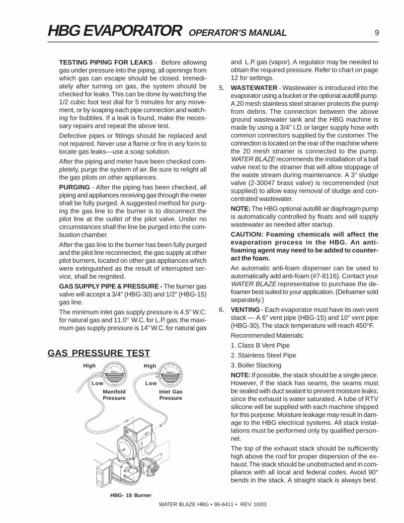
GAS SUPPLY PIPE & PRESSURE - The burner gasvalve will accept a 3/4" (HBG-30) and 1/2" (HBG-15)gas line.
The minimum inlet gas supply pressure is 4.5" W.C.for natural gas and 11.0" W.C. for L.P. gas; the maxi-mum gas supply pressure is 14" W.C. for natural gas
and L.P. gas (vapor). A regulator may be needed toobtain the required pressure. Refer to chart on page12 for settings.
5. WASTEWATER - Wastewater is introduced into theevaporator using a bucket or the optional autofill pump.A 20 mesh stainless steel strainer protects the pumpfrom debris. The connection between the aboveground wastewater tank and the HBG machine ismade by using a 3/4" I.D. or larger supply hose withcommon connectors supplied by the customer. Theconnection is located on the rear of the machine wherethe 20 mesh strainer is connected to the pump.WATER BLAZE recommends the installation of a ballvalve next to the strainer that will allow stoppage ofthe waste stream during maintenance. A 3" sludgevalve (2-30047 brass valve) is recommended (notsupplied) to allow easy removal of sludge and con-centrated wastewater.
NOTE: The HBG optional autofill air diaphragm pumpis automatically controlled by floats and will supplywastewater as needed after startup.
CAUTION: Foaming chemicals will affect theevaporation process in the HBG. An anti-foaming agent may need to be added to counter-act the foam.
An automatic anti-foam dispenser can be used toautomatically add anti-foam (#7-8116). Contact yourWATER BLAZE representative to purchase the de-foamer best suited to your application. (Defoamer soldseparately.)
6. VENTING - Each evaporator must have its own ventstack — A 6" vent pipe (HBG-15) and 10" vent pipe(HBG-30). The stack temperature will reach 450°F.
Recommended Materials:
1. Class B Vent Pipe
2. Stainless Steel Pipe
3. Boiler Stacking
NOTE: If possible, the stack should be a single piece.However, if the stack has seams, the seams mustbe sealed with duct sealant to prevent moisture leaks;since the exhaust is water saturated. A tube of RTVsilicone will be supplied with each machine shippedfor this purpose. Moisture leakage may result in dam-age to the HBG electrical systems. All stack instal-lations must be performed only by qualified person-nel.
The top of the exhaust stack should be sufficientlyhigh above the roof for proper dispersion of the ex-haust. The stack should be unobstructed and in com-pliance with all local and federal codes. Avoid 90°bends in the stack. A straight stack is always best.
GAS PRESSURE TEST
HBG- 15 Burner
High
Low
High
Low
Inlet GasPressure
ManifoldPressure

10 HBG EVAPORATOR OPERATOR’S MANUAL
WATER BLAZE HBG • 96-6411 • REV. 10/03
A vertical discharge design should be used, togetherwith a vertical rain diverter. A conventional rain capis not recommended for the HBG because of inducedback pressure. A vertical rain diverter is an over-sized piece of stack material that is concentric withthe stack. The diverter extends 6" down over the topof the stack to allow flexibility in positioning fasten-ers. Both rain protection and back pressure reduc-tion is achieved with this design. This type of raindiverter can be purchased from your local dealer.
7. Air Requirements - An air compressor capable ofdelivering a minimum of 4 cubic feet per minute (CFM)of air at 60-100 psi to work the optional auto fill airdiaphragm pump and air assisted defoamer system.NOTE: Air supply must be on at all times for ma-chine to operate.
2' Min.
6" Flue Rain Cap (optional)#7-10044
10" Flue Rain Cap(optional) #7-100451
Roof
YES NO
Has gas supply been inspected by anauthorized contractor to meet localcodes?
Has air supply hose been connected andadjusted?
Is machine shielded from moisture orwater spray?
Is the voltage correct and are the circuitbreaker and supply cord adequateaccording to specifications and serialplate notation?
Is the machine electrically grounded?
Is there ample wastewater supply?
Have all flammable liquids or gases beenremoved from the installation location?
Is there adequate gas supply for the BTUrating of the burner?
Is incoming gas supply pressure to themachine between 6-14 w.c.i. or 1/2 psig?
Has the proper gas regulator beeninstalled for pressure and volume?
Is the machine properly vented to allowadequate flow?
Are the propane tanks large enough,according to the rating of the machine, toprevent freezing?
Have gas lines been checked for gasleaks?
Have all operators using this machinebeen instructed properly and have theyread the manual?
Has the machine been installedaccording to the operator's manualinstructions?
Has wastewater pH been adjustedbetween 8 - 10?
PRE-START CHECK LIST
CAUTION: If “NO” has been checked on any of theabove questions, do not operate the machine.

HBG EVAPORATOR OPERATOR’S MANUAL 11
WATER BLAZE HBG • 96-6411 • REV. 10/03
OPERATING INSTRUCTIONSNOTE: If the waste stream being evaporated does notcontain between 500-5000 mg/L of oil and you areusing a mild steel tank, it is extremely important toadd 1 quart of 20 to 40 weight chemical oil to theHBG-15 tank (2 quarts to the HBG-30 tank) each timemaintenance is performed. This amount of oil willequal approx. 1/8" of oil on the top surface of theHBG liquid. This additive will impede corrosion. Ifthis operation is not performed, the tank warranty willbe void.
1. Supply the HBG-15/30 with 120 volts on a 15 ampservice. Note: All supply voltage wires must be wiredinto the electrical box and connected to their respec-tive terminal bar strip positions or grounding lugs.Refer to wiring diagram supplied with the machine.
2. Fill the evaporator tank with wastewater to the bot-tom of the top safety float. Warning: If the HBG liq-uid level is too high, the high level safety float willnot allow the machine to operate.
3. Turn the fan switch to the ON position.
NOTE: The fan switch must be on for any other com-ponents to operate.
4. If equipped with the optional auto fill air diaphragmpump, confirm the wastewater inlet line is connectedto the inlet filter garden hose swivel connector.
5. Confirm that the external normally open float withthe auto fill option in the wastewater holding tank isin the up position. If the float is in the down positionwhen the pump switch is in the auto position, thepump will not operate. If the pump switch is in themanual position the external float will be bypassed.
6. Push the pump switch to the “auto” position (auto filloption). The pump will turn on, filling the tank withwastewater. The top float inside the tank turns thepump “off.”
7. Turn gas control valve knob to “ON”.
8. Push the burner switch to the “ON” position. If thelow water float is in the up position the burner beginsthe ignition process.
NOTE: The low water float is controlled by a timer toalleviate the burner from being turned on and off dueto boiling water agitation. When the low water float ismoved from the down to the up position, the timerwill initiate timing for 10 seconds before the burner isinitiated.
The ignition process is as follows:
A. Trial for pilot ignition: The flame module checksthat a safe start flame simulating condition exists.A fan proving switch proves the burner fan is oper-ating. If it is not operating, the burner will not ig-nite.
B. Pilot ignition: The flame module opens the gaspilot valve. Simultaneously, the electronic sparkgenerator ignites the pilot. Once the pilot has igni-tion, the electronic spark generator turns off.The pilot ignitor/sensor rod proves there is flameat the pilot. If there is no flame at the pilot theburner goes into a safety lockout period.
C. Main flame ignition: Once the burner pilot sensoris proven the main gas solenoid valve opens al-lowing full burner operation. If the flame goes out,the pilot electronic spark generator attempts to re-ignite the pilot.
NOTE: If the burner does not ignite, confirm thegas solenoid valve on/off switch is in the “ON” po-sition and that the manual reset high temperatureswitch has not tripped due to low water or highsolids build up inside the HBG tank. The reset but-ton is on the back of the control box.
9. Remove the plug at the gas solenoid valve manifoldand install a hosebarb fitting. Attach a 0-10" W.C.manometer. With the burner operating, adjust the regu-lator valve to the proper setting according to the chartbelow.
10. When the predetermined batch cycle count has beenreached and after maintenance has been performed,restart the machine by pushing the reset button onthe batch cycle counter labeled F1/RST.
11. To operate the optional oil skimmer, turn the burnerto the “OFF” position allowing oil to float to the top ofthe tank. Lift the tank lid and attach the oil skimmerto the outer wall of the tank. Allow the stainless beltto pick up all the floating oil in the wastewater tank.Place a bucket under the downspout of the oil skim-mer to collect the oil.
The evaporator will operate continuously until 1) thebatch controller hits its predetermined number ofbatch cycles. 2) the water gets too low in the waste-water holding tank (auto fill option). 3) the water levelin the wastewater tank causes the bottom float totrip off the burner. Once the liquid level float has risen,the burner will automatically restart.

12 HBG EVAPORATOR OPERATOR’S MANUAL
WATER BLAZE HBG • 96-6411 • REV. 10/03
HBG FUEL AND AIR SETTINGS
Natural Gas GPH Gas Oriface Inlet Gas Supply Pressure Man. Pressure Air Setting
HBG-15D 10 - 15 G (.261) 4.5 - 14 WCI 3.5 WCI Open Draft Wheel 6 Full Turns
HBG-30D 25 - 30 15/32 5.5 - 14 WCI 4.0 WCI Draft Open to 4
Liquid Propane GPH Gas Oriface Inlet Gas Supply Pressure Man. Pressure Air Setting
HBG-15D 10 - 15 #22 (.157) 11 - 14 WCI 10 WCI Open Draft Wheel 6 Full Turns
HBG-30D 25 - 30 Q - (.332) 5.5 - 14 WCI 3.75 WCI Draft Open to 4
MAINTENANCECAUTION: Use protective gloves, goggles and anyother protective clothing required by law for chemi-cals mixed with the waste stream.The HBG does not require a lot of maintenance, but itdoes require consistent maintenance. The frequency ofmaintenance varies depending on what is in the waterthat is being evaporated.
General maintenance consists of removal of sludge fromthe bottom and removal of any floating oil at the top ofthe evaporation tank.
WARNING - Shut down the HBG and allow it to cool be-fore performing any maintenance. Do not allow pump torun longer than 5 minutes without water. Disconnect allhoses to allow water to drain.
OIL REMOVAL - If you have excess floating oil in theevaporation tank liquid that needs to be removed, shutdown the HBG and let the oil float to the top. Attach oilskimmer to side of tank and plug into own power source.Turn on the oil skimmer and collect oil in a bucket.
SLUDGE REMOVAL - Remove the lower 3" sludge draincap on the side of the evaporator allowing sludge andwater to escape. Use a small shovel to remove the re-sidual sludge from the bottom of the tank. Removing thesludge and cleaning the floor of the evaporator will greatlyimprove the evaporation rate.
NOTE: Allowing sludge to accumulate on the floor of theHBG can cause warpage, corrosion and or heat stress tothe floor. A build-up of solids will cause the manual resethigh temperature switch to trip not allowing the burner orpump to operate. Remove the sludge, refill the tank andrestart the machine.
WARNING: Allowing sludge to build up on the insidefloor of the HBG can cause warpage to the floor ofthe tank and will void the warranty.DRAFT INDUCER: On a monthly maintenance sched-ule, cleaning of the fan blade fins and exhaust stackingmust be done to remove any sludge build-up that canreduce the evaporation efficiency. To clean the fan bladefins, start with the water cool and the fan switch on thecontrol panel in the off position. Next, remove the six tekscrews that attach the fan to the stack. Pull the inducer
fan away from stack and scrape debris from blade fins.On reassembly, place a small bead of high heat siliconearound the outer edge of the inducer housing on each tekscrew to seal out any possible air leaks.
WEEKLY MAINTENANCE 1. Turn all power switches to the “OFF” position.
2. Allow the wastewater to cool.
3. Position a sludge container under the sludge valve.Open the sludge valve and remove the remainingwaste liquid.
4. After every complete batch, scrape the floor and in-terior walls of the HBG tank, transferring the sludgeinto the sludge container.
5. Remove any buildup that has accumulated on theexterior of the tank and exhaust pipe.
6. Clean the liquid level floats, remove any accumula-tion that may coat the floats and not allow them tomove more freely.
7. Clean the screen of the wastewater filter if auto fill isinstalled on the machine.
8. If the evaporator is not in use at least twice per week,then clean out and rinse with fresh water, and let sitempty.
9. Check tank and lid for corrosion after each completebatch.
SEMI ANNUAL MAINTENANCE 1. Check auto fill pump for proper pressure, flows and
electrical capacities.
2. Check auto fill floats for proper operation.
3. Oil the draft inducer motor bearings. Oil holes areprovided at front and rear faces of motor. Caution:Not more than 3 drops of S.A.E. 20 oil should beused.
4. Check tank and lids for corrosion.
5. Check burner for proper operation and gas pressure.

HBG EVAPORATOR OPERATOR’S MANUAL 13
WATER BLAZE HBG • 96-6411 • REV. 10/03
AUTO FILL OPERATINGCHARACTERISTICSThe auto fill option consists of two level control switcheswhich control the fill pump. The lower level switch turnsthe pump on. As the water level raises, the upper levelswitch turns the pump off. The evaporator then evapo-rates the water, which in turn lowers the water level pastthe lower level switch, which turns the pump on and startsthe fill process.
Note: To engage the auto fill feature, push the pump switchto auto. This will allow the pump to be controlled by theauto fill float level switches. Pushing the pump switch tomanual will bypass the external N/O tethered float in thewastewater holding tank.
AIR ASSISTED DEFOAMEROPERATINGCHARACTERISTICSThe air assisted defoamer option consists of a meteringpump drawing up defoamer and a solenoid controlling theair injecting the defoamer through a fan nozzle locatedinside the wastewater tank. Set the three position switchto “auto” and defoamer will then be injected every timethe machine refills. If more defoamer is needed, turn ad-justment screw, located behind white cap in front of pump,clockwise to increase pump speed. Injecting manually isalso available. NOTE: The air pressure needed to operatethe defoamer must not exceed 2 psi.

14 HBG EVAPORATOR OPERATOR’S MANUAL
WATER BLAZE HBG • 96-6411 • REV. 10/03
Batch Cycle Counter QuickReprogramming Instructions
Function SettingsReset Button. Push to restart machine after batch cycle completed.
Scroll Button. Push to select the different programming modes. Also savesprogram values.
Vertical Scroll changes programming values.
Horizontal Scroll for multiple values. Also changes programming values.
▲
1. Pull face plate of batch cycle counter out of its holder in electrical box with your fingers . Dip switch #7,located along left side (wall) of circuit board, needs to be switched to the down (OFF) position. This willallow for reprogramming. Slide batch counter back into its holder.
2. Press button until LED screen in green shows ( #02 ). Push the ▲ or button until the new batchcycle count appears in green. Then press the button once to save the setting for preset 1.
3. Press button once more. The LED screen in green will show ( #02 ). Push the ▲ or until thevalue in green is the same value in preset 1. Press button to save setting for preset 2.
4. Remove batch cycle counter once again from its holder in the electrical box. Change the setting on dipswitch #7 to the up (ON) position. Slide the batch counter back into its holder in the electrical box.
NOTE: # stands for batch count value
Electrical Box
Holder
Pry Slot
Face Plate
DipSwitches

HBG EVAPORATOR OPERATOR’S MANUAL 15
WATER BLAZE HBG • 96-6411 • REV. 10/03
13. Press button, (P1tr Ac) will appear in red. Value(no) will appear in green. No change is necessary.
14. Press button, (Ac Out) will appear in red.(-L-L-L) will appear in green. No change is necessary.
15. Press button, (OutrES) will appear in red.(0.01SEC) will appear in green. No change is neces-sary.
16. Press button, (OutPut) will appear in red.(1t 0.10) will appear in green. No change is necessary.
17. Press button, (OutPut) will appear in red.(2t 0.10) will appear in green. No change is necessary.
18. Press button, (OutPut) will appear in red.(3t 0.10) will appear in green. No change is necessary.
19. Press button, (rEUOut) will appear in red.(-n-n-n) will appear in green. Press button until middle(-n) value is blinking. Press ▲ button until (-y) value isshowing.
20. Press button, (rEUAnu) will appear in red.(-n-n-n) will appear in green. No change is necessary.
21. Press button, (OutP.uP) will appear in red.(PPP) will appear in green. Press button until left(P) value is blinking. Press ▲ button until (P) value ap-pears. Do the same for center and right, all values shouldread (-P)
22. Press button, (USr In 1) will appear in red.(rSt. -L) will appear in green. Press ▲ button until(Pro.dis) appears.
23. Press button, (USr FI) will appear in red. (rst-L) will appear in green. No change is necessary.
24. Press button, (CodE) will appear in red. Value(0) will appear in green. No change is necessary.
25. Press button, (ScroLL) will appear in red. (no)will appear in green. No change is necessary.
26. Press button, (FAcSEt) will appear in red. (no)will appear in green. No change is necessary.
27. Press and hold button for 2 seconds. (Prog)will appear in red and (SAVE) will appear in green.
To complete setting the batch counter, first pull the faceplate of the batch counter out of its holder with your fin-gers. This will expose the internal circuit boards. Alongthe left side (wall) circuit board are the dip switches. Theseswitches are numbered 1 through 7. Switches 2, 5, and7 need to be in the up (ON) position.
Slide the batch counter back into its holder. Initial pro-gramming of the batch cycle controller is now complete.
(NOTE: Programming cannot be performed if dip switch#7 in the up (ON) position). If adjustment to the batchcycle count value is to be reprogrammed, dip switch #7needs to be in the down (OFF) position. When repro-gramming is complete, set dip switch #7 back to the up(ON) position).
INITIAL PROGRAMMING OFBATCH CYCLE COUNTERFunction Settings
Reset Button. Push to restart machine after batchcycle completed.
Scroll Button. Push to select the different pro-gramming modes. Also saves program values.
Vertical Scroll changes programming values.
Horizontal Scroll for multiple values. Also changesprogramming values.
NOTE: Original batch counter has been preset atfactory.
Programming 1. Press and hold button for 2 seconds. (Entry)will appear in red. (Auto Sc) will appear in green. Nochange is necessary.
2. Press button once, (Ac PSc) will appear in red.(-L) will appear in green and does not need to bechanged.
3. Press button, (PSc ALr) will appear in red.(1.00000) will appear in green and does not need to bechanged.
4. Press button, (dEc Pt) will appear in red.(------) will appear in green. This value can't be changed.
5. Press button, (Cnt In) will appear in red. (Cl-ud)will appear in green. No change is necessary.
6. Press button, (OPEr 1) will appear in red. (11)will appear in green. Press button until (1) is showing.
7. Press button, (C2 ASn) will appear in red.(bAtch) will appear in green. No change is necessary.
8. Press button, (OPEr 2) will appear in red. (1)will appear in green. No change is necessary.
9. Press button, (Ac PrS) will appear in red.(-y-y-y) will appear in green. Press button until the farleft (-y) value is blinking. To change, press ▲ button until(-L) is showing. Press once, the middle (-y) value willblink. Press ▲ button until (-n) is showing. Press button once more and the far right (-y) will blink. Presss button until (-n) is showing.
10. Press button, (PrESEt) will appear in red. Thevalue to set is predetermined from the wastewater analy-sis. This value is known as PRS1 (Preset 1). Press the▲ or buttons to set the batch cycle value.
11. Press button, (PrESEt) will appear in red. Thisvalue, PRS2 (preset 2), must be set with the same valueas (preset 1). Press the s or buttons to set value.
12. Press button, (PrESEt) will appear in red. Thisis (preset 3) and must be set with the value 999999. Pressand hold the ▲ button until achieved.
▲▲▲▲▲

16 HBG EVAPORATOR OPERATOR’S MANUAL
WATER BLAZE HBG • 96-6411 • REV. 10/03
TRAHCSGNITTES
EDOM GNITTESEULAV
yrtnE cSotuA
cSPcA L-
rLAcSP 1
nIcEd ------
tPtnC du-IC
IrEPO 1
nSA2C hctAb
2rEPO 1
SrPcA n-n-L-
tESErP eulavelcychctabremotsuC
tESErP eulavelcychctabremotsuC
tESErP 999999
cArtlP on
tuOcA L-L-L-
SErtuO CES10.0
tuPtuO 01.0t1
tuPtuO 01.0t2
tuPtuO 01.0t3
tuOUEr n-y-n-
unAUEr n-n-n-
Pu.PtuO P-P-P-
InIrSU sid.orP
IFrSU L-tsr
Edoc 0
llorcS on
tEScaF on
noitisop)NO(punitesera7,5,2sehctiwspiD

HBG EVAPORATOR OPERATOR’S MANUAL 17
WATER BLAZE HBG • 96-6411 • REV. 10/03
INSTALLATION DIMENSIONSHBG-15 HBG-30
29" toPowerSupply
90"
53"
70"
10" Dia. Exhaust Stack
HBG-15
78-1/2"
21-1/4"
23-1/4"
6" Dia. Exhaust Stack
65"
15" To Pump
3-1/2"To Gas Supply
33-1/4"
HBG-30
14-1/2" to Pump
Float Box
Float Box
29"To PowerSupply
21-1/4"

18 HBG EVAPORATOR OPERATOR’S MANUAL
WATER BLAZE HBG • 96-6411 • REV. 10/03
EXPLODED VIEWLEFT SIDE • HBG-15
18
7
5
23
6
4
320
24
21
22
108
9
▲▲▲▲▲
45
10
16
1540
2
1342
444341
1
16
14
10
40
39
15
46
58
57
47 11
5667
63
60
65
27
64
12
17
29
48
59
ForDetail
See ControlPanel
▲▲▲▲ ▲
66
FoamInjectorAssy
ForDetail
See FloatBox Illus.
30-817

HBG EVAPORATOR OPERATOR’S MANUAL 19
WATER BLAZE HBG • 96-6411 • REV. 10/03
EXPLODED VIEWRIGHT SIDE • HBG-15
52
54
51
28
16
55
1628
55
50
2616
14 49
30
34
3332
31
53
35
19
25
68

20 HBG EVAPORATOR OPERATOR’S MANUAL
WATER BLAZE HBG • 96-6411 • REV. 10/03
HBG-15 EXPLODED VIEWPARTS LIST
ITEM PART NO. DESCRIPTION QTY
1 95-074303 Panel, Front 1
2 95-074304 Panel, Left Side 1
3 95-074000951 Bracket, Handle 1
4 95-07400095 Pipe, 1/2" X 32.5" 1
5 2-01404 ▲ Snap Bushing, 7/8" 2
6 2-01102 Grip, 7/8" 2
7 95-074000961 ▲ Lid, Top Inside Shell, 316LSS 1
95-07400097 Lid, Hinged Outside Shell 1
7-0137 ▲ Insulation, Rigid Foam,1/2" 2.5 ft.
2-4037 ▲ Pad, HBG Lid, 1/4" 2
8 90-50203 Hinge, 2" x 36" Piano, Stainless1
9 90-4999 Rivet, 1/4" x 3/8" Grip, Blind SS 15
10 90-19995 Screw, Cap 10/32" x 3/4"BH, HF, SS, Soc 57
11 5-1511 Fan, Draft Inducer, D-3 1
12 95-074302 Panel, Top, 316L SS 1
7-100432 ▲ Flue Adapter, 6" 1
13 95-074300 Tank Assembly, Carbon Steel 1
95-0743001 Tank Assembly, 316L SS 1
95-0743002 Tank Assembly, AL-6XN SS 1
95-074135 ▲ Shovel, Clean Out 1
14 90-2020 Nut, Cage, 3/8" x 12 Gauge 23
15 90-1802 Screw, 1/4"-20 x 3/4" PhilPH SS M/S 9
16 90-2018 Nut, Cage, 10/32" x 16 Gauge100
17 2-004984 Pipe, Cap, 3" Black Pipe 1
2-0049841 Pipe, Cap, 3", 316LSS 1
2-30047 ▲Valve, 3" Brass, Ball (Optional)1
18 10-9009 Label, Landa WATER BLAZESystem 1
19 10-02025A Label, Hot/Caliente 3
20 10-50182 Label, Steam Warning 1
21 95-074133 Support, Lid Lock, HBG 1
22 90-10151 Bolt, 3/8" Shoulder 2
23 90-2001 Nut, 5/16" ESNA 5
24 90-2021 Nut, Cage, 5/16" x 16 Gauge 1
25 7-00045 Burner, P-250 AFEP, NG 1
7-00047 Burner, P-250 AFEP, LPG 1
ITEM PART NO. DESCRIPTION QTY
26 90-1016 Bolt, 3/8" x 1", NC, H 3
27 2-1037 Tee, 1/4" Branch, Male 1
28 90-10141 Screw, 10/32" x 1/2" SS 14
29 10-08014 Label, Made in USA 1
30 95-074301 Fire Box W/Insulation 1
7-014842 ▲ Insulation, 1" x 2" 15 ft.
31 95-07700011 Leveling, Foot Assembly 4
32 90-20082 Nut, 1/2" Hex 4
33 90-40091 Washer, 1/2" Lock 4
34 90-10162 Bolt, 3/8" x 1", NC HH SS 20
35 90-4002 Washer, 3/8" 20
36 90-4001 ▲ Washer, 5/16" 4
37 10-02023 ▲ Label, Liquid Propane 1
10-02024 ▲ Label, Natural Gas 1
38 90-2002 ▲ Nut, 3/8" ESNA 4
39 90-1991 Screw, 10/32" x 1/2", BHSOC 4
40 90-2000 Nut, 1/4" ESNA 9
41 90-1006 Bolt, 5/16" x 3/4" 4
42 90-2023 Nut, 5/16" x 12 Gauge, Black 1
43 95-074309 Standoff, Electric Box 1
44 95-074128 Panel, Right Side 1
45 95-074305 Panel, Rear 1
46 2-001338 ▲ Nipple, 1" x 4", 316L SS 1
47 2-00134 Nipple, 1" x 4" 1
48 95-074308 Lid, Burner Cover 1
49 95-074306 Cover, Burner Assembly 1
50 95-074817 Side Panel, Left, Plenum 1
51 95-074820 Cover, Plenum 1
52 95-074818 Side Panel, Right, Plenum 1
53 95-074821 Cover, Fan Shield 1
54 95-074819 Lower Cover, Plenum 1
55 7-0143 Insulation, Blanket - No Foil,1/2" x 24" 6
56 90-30011 Screw, #12 x 3/4", TEK 6
57 2-00295 Elbow, 1" x 3/4", Reducing 1
58 2-00151 Nipple, 3/4" Close 1
59 90-017 Nut, 10/32" Keps 15
60 2-9040 Clamp, Hose 3
61 6-02177 ▲ Elbow, Hose Barb, 1/4" Barb x1/4" Pipe 2

HBG EVAPORATOR OPERATOR’S MANUAL 21
WATER BLAZE HBG • 96-6411 • REV. 10/03
HBG-15 EXPLODED VIEWPARTS LIST (CONTINUED)
ITEM PART NO. DESCRIPTION QTY
62 2-1059 ▲ Nipple, 3/4" x 1/2" Pipe 1
63 2-3070 Valve, 1/4" Check 1
64 2-1022 Elbow, 1/4" Street 1
65 2-1002 Nipple, 1/4" Close 1
66 2-00265 Elbow, 1/4" Street 1
67 2-1089 Hose Barb, 1/4" Barb x1/4" Pipe 3
68 90-20040 Nut, 3/8" Whiz Loc 4

22 HBG EVAPORATOR OPERATOR’S MANUAL
WATER BLAZE HBG • 96-6411 • REV. 10/03
EXPLODED VIEWLEFT SIDE • HBG-30
1
6
15
11
3
5
31
7
12
2
32
16
14
17
29
13
33
5
34
27
35
ForDetail SeeFloat Box
Illus.30-8171
7
8 10
9
ForDetail SeeControlPanelIllus.
4
7
31
47
30
36
38
47
49
4039
32
4337
29 41
39
40
43
4542
1
35
44
35
44For
Detail SeeDefoamer
Illus.
51
29
50
3152
2
45
32

HBG EVAPORATOR OPERATOR’S MANUAL 23
WATER BLAZE HBG • 96-6411 • REV. 10/03
EXPLODED VIEWRIGHT SIDE • HBG-30
26
2430
29
26
26
23
1829
27
21
19
29
29 2728
27
2722
29
20
27
29
33
48
46
543743
17
53
27
25
27

24 HBG EVAPORATOR OPERATOR’S MANUAL
WATER BLAZE HBG • 96-6411 • REV. 10/03
HBG-30 EXPLODED VIEWPARTS LIST
ITEM PART NO. DESCRIPTION QTY
1 95-074803 Lid, Top 2
2 90-50203 Hinge, 2" x 72" Piano, Stainless2
3 95-074133 Support, Lid, HBG 1
4 95-074808 Support, Lid 1
5 2-01194 Handle, Lid SJ 2
6 10-50182 Label, Steam Warning, Hot Box1
7 90-1992 Screw, 3/8" x 3/8", SCKT, SHDR4
8 95-074804 Guard, Splash 1
9 95-074808 Assy, Top Panel 1
7-100433 Adapter, Flue, 10" 1
10 5-1511 Fan, Draft Inducer D-3, 1
11 95-074800 Assy, Tank, Carbon Steel 1
95-0748001 Assy, Tank 316L SS 1
95-0748002 Assy, Tank, AL-6XN 1
95-074135 ▲ Shovel, Clean-Out 1
12 95-074832 Panel, Drain End 1
13 95-074831 Panel, Burner End 1
14 95-074307 Bracket, Electrical Box 1
15 95-074830 Panel, Rear 1
16 95-074833 Panel, Front 1
17 95-074837 Top, Burner Cover 1
18 95-074814 Lower Cover, Plenum HeatShield 1
19 95-074816 Cover, Fan Shield 1
20 95-074813 Panel, Right Side 1
21 95-074812 Panel, Left Side 1
22 95-074834 Cover, Plenum 1
23 95-07700011 Foot, Leveling 5
24 95-07105010 Assy, Fire Box 1
ITEM PART NO. DESCRIPTION QTY
25 95-074835 Wall, Burner Cover, Left 1
26 7-00046 Burner, Wayne, HSG-400 1
27 90-1991 Screw, 10/32" x 1/2" BHSOC 12
28 7-0143 Insulation, Blanket, No-Foil,1/2" x 24" 8
29 90-2018 Nut, Cage, 10/32" x 16 Gauge 56
30 90-2020 Nut, Cage, 3/8" x 12 Gauge 24
31 90-2023 Nut, Cage, 5/16" x 12 Gauge 5
32 90-1802 Screw, 1/4"-20 x 3/4" Phil, PH,SS 12
33 90-10162 Bolt, 3/8" x 1" HH/NC, 316 SS 18
34 90-30991 Washer, 3/8" S/S Flat 18
35 95-074801 Lid, Bottom, 16 Gauge 316L 2
36 2-004984 Cap, Pipe, 3" Black Pipe 1
2-0049841 Cap, Pipe, 3" 316L SS 1
2-30047 ▲ Valve, 3" Brass (Optional) 1
37 2-9013 Clip, Conduit 9
38 70-9009 Label, Landa WastewaterEvaporator 1
39 90-4001 Washer, 5/16" Flat 8
40 90-2001 Nut, 5/16" ESNA 2
41 90-20001 Nut, 1/4" ESNA, SS 5
42 90-1802 Screw, 1/4"-20 x 3/4" Phil, PH,SS, M/S 5
43 90-19995 Screw, Cap, 10-32 x 3/4" 53
44 7-0137 Insulation, Rigid Foam, 1/2" 1
45 90-4999 Rivet, 1/4" x 3/8" Grip, Blind SS30
46 10-02025A Label, Hot/Caliente 1
47 90-020 Nut, 10-32, SS 46
48 90-20040 Nut, 3/8" Whiz Loc 4
49 4-050838 Thermocouple, SS Sheath, 34" 1
50 90-19996 Screw, 10-23 x 1/2" BH,SOC SS 6
51 90-1044 Screw, 1/4"-20 x 2" SHCS, Zinc 4
52 90-2022 Nut, Cage, 1/4" x 16 Gauge 4
53 95-074836 Wall, Burner Cover, Right 1
54 90-017 Nut, 10-32 Keps 1
▲ Not Shown

HBG EVAPORATOR OPERATOR’S MANUAL 25
WATER BLAZE HBG • 96-6411 • REV. 10/03
CONTROL PANELHBG-15, HBG-30 Exploded View and Parts List
1
ITEM PART NO. DESCRIPTION QTY
1 6-020251 Switch, Curvette 4
2 6-0205 Switch, Momentary Push 1
3 6-03522 Relay, 120V, 4PDT 1
4 6-035221 Base, Relay, 120V, 4PDT 1
5 6-021595 Din Rail, 35MM 19"
6 6-03621 Relay, 120V, 2PDT 5
7 6-03541 Base, Relay, 2PDT 5
8 6-03676 Counter, Red Lion 1
9 6-03721 Timer, Variable Time 1
10 6-03913 Box, Plastic, 14" x 16" x 6-3/4"w/Hinged Lid 1
11 6-05040 Block, Terminal, 8 Pole 1
12 6-4000 Contactor, 120V, CH 1
ITEM PART NO. DESCRIPTION QTY
13 4-050822 Hour Meter, 115/240VAC 1
14 4-050842 Hi Limit Control, ETR-3-02 1
15 6-05159 Connector, 1/2" LT 5
16 6-05153 Strain Relief, STRT, LQ Tite 1
17 6-05152 Strain Relief, STRT, LQ Tite Sm 3
18 6-020530 Light, Indicator, Green, 125V 3
19 6-050413 Light, Amber, 125V 1
20 6-050418 Light, Blue, 14V 1
21 6-050416 Light, Blue, 125V 2
14
13
18
21
20
1219
18
39
4
75
6
17
8
11
16
15
2
10

26 HBG EVAPORATOR OPERATOR’S MANUAL
WATER BLAZE HBG • 96-6411 • REV. 10/03
FLOAT ASSEMBLYHBG-15 EXPLODED VIEW 30-817
4
1713
13 11
10
11
10
4
15
14
1
8
3
2
5
12
16
18
8
PumpOff
BurnerOff
HighWater
Pump On (AutoFillOption)
19
18
20
96
21

HBG EVAPORATOR OPERATOR’S MANUAL 27
WATER BLAZE HBG • 96-6411 • REV. 10/03
FLOAT ASSEMBLYHBG-15 PARTS LIST
ITEM PART NO. DESCRIPTION QTY
1 90-020 Nut, 10/32" NF ST KEP 4
2 95-074160 Rod, Float, 1/4" x 23" 1
3 95-074161 Rod, Float, 1/4" x 15.5" 1
4 4-0490 Float, 3-1/2" Ball, Steel 2
5 95-074162 Cover, Liquid Level Switch 1
▲ Label, Keep Floats Free ofDebris 1
6 95-074163 Housing, Liquid Level Switch 1
7 90-2018 Nut, Cage, 10/32" x 16 Gauge 4
8 90-1991 Screw, 10/32" x 1/2" BH SOC,Black 4
9 6-051599 Connector, 90°, Black 1
10 90-128 Screw, 4"-40 x 3/4", Slotted P/HM/S, Zinc 8
11 90-20042 Nut, 4"-40 Keps, Zinc 16
12 90-19995 Screw, 10/32" x 3/4" BH SOC,SS 4
13 6-0801 Switch, Micro, V3L1101D8,Roller Level 4
14 90-20055 Nut, 1/4"-20, SS 2
15 90-40008 Washer, 1/4" Split, SS 2
16 2-0167 Bearing, Plastic 4
17 6-03941 Switch, Liquid Level, SS, N/C 1
18 90-200415 Collar, Shaft, Small 4
19 90-200416 Collar, Shaft, Large 2
90-3015 Set Screw, 8/32" x 1/8" 6
20 90-4014 Washer, 7/16", Self-LockingRetaining Wing 2
21 10-08021 Label, Disconnect PowerSupply 1
▲ Not Shown

28 HBG EVAPORATOR OPERATOR’S MANUAL
WATER BLAZE HBG • 96-6411 • REV. 10/03
FLOAT ASSEMBLYHBG-30 EXPLODED VIEW
7
7
4
15
9
13
7
7
9
15
11
20
2
6
14
13
8
5*
18
4
12
19
1
11
7
5*
5*
12
3
4
12
7
17
TankLid
NC
NO
NC
NC
Pump On(Auto-FillOption)
Pump Off(Auto-FillOption)
16
BurnerOff
HighWater
*Position of magnetsmust be placed as
shown

HBG EVAPORATOR OPERATOR’S MANUAL 29
WATER BLAZE HBG • 96-6411 • REV. 10/03
FLOAT ASSEMBLYHBG-30 PARTS LIST
ITEM PART NO. DESCRIPTION QTY
1 10-5013 Label, WB, Keep Floats Free 1
2 4-0490 Float, 3-1/2" Ball, Steel 2
3 6-02074 Switch, Magnetic Reed, NO 1
4 6-02075 Switch, Magnetic Reed, NC 3
5 6-02076 Magnet, Reed Switch 4
6 6-03941 Switch, Liquid Level 1
7 90-127 Screw, 4"-40 x 1/2" 16
8 90-19996 Screw, 10/32" x 1/2" 4
9 90-18061 Screw, 1/4" x 1/2", 7, 316L 2
10 90-18062 Screw, 10/32" x 1/2" 2
11 90-19995 Screw, 10/32" x 3/4" 6
12 90-20042 Nut, 4-40 Keps 16
13 90-020 Nut, 10/32" SS 4
14 90-2018 Nut, Cage, 10/32" x 16 Gauge 6
15 90-40008 Washer, 1/4" Split Ring Lock 2
16 95-074809 Lid, Float Box 1
17 95-074825 Rod, Float, Long 1
18 95-074826 Rod, Float, Short 1
19 95-074827 Plate, Switch Mount 1
20 95-074828 Box, Float 1
▲ Not Shown

30 HBG EVAPORATOR OPERATOR’S MANUAL
WATER BLAZE HBG • 96-6411 • REV. 10/03
HBG OPTIONSAUTO FILL EXPLODED VIEW
14
19
6
17
8 8
8
10
1211
12
11
19
18
11
137
9
1
2
3
15
4
17
16
5
19

HBG EVAPORATOR OPERATOR’S MANUAL 31
WATER BLAZE HBG • 96-6411 • REV. 10/03
HBG OPTIONSAUTO FILL PARTS LISTITEM PART NO. DESCRIPTION QTY
1 2-00134 Nipple, 1" x 4", Black Pipe 1
2 2-00295 Elbow, 1" x 3/4", Reducing Blk 1
3 6-140160 Solenoid Coil, 120V 1
4 2-10636 Nipple, 3/4" JIC x 3/4" Pipe 1
5 4-02120000 Hose, 3/4" Push-On 1.66 ft.
6 2-10630 Elbow, 3/4" JIC x 1/2", 90° 1
7 5-1951 Pump, Air Diaphragm, 1/2" Poly1
8 2-1902 Strainer, Inlet Garden Hose 1
9 2-001338 Nipple, 1" x 4", 316L SS 1
10 2-99075 Filter, Inlet 1
11 90-4001 Washer, 5/16" Flat, SAE 8
12 90-1007 Bolt, 5/16" x 1", NC HH 4
13 2-1059 Nipple, 3/4" Pipe x 1/2" Pipe 1
14 95-07400079 Bracket, Pump Support, Black 1
15 6-140158 Valve, Solenoid, Parker 1
16 6-0128 Conduitm Flex, Water Tight 6 ft.
17 2-11050 Swivel, 3/4" SAE Female,Push-On 2
18 90-2001 Nut, 5/16" ESNA, NC 4
19 90-2002 Nut, 3/8" ESNA 4

32 HBG EVAPORATOR OPERATOR’S MANUAL
WATER BLAZE HBG • 96-6411 • REV. 10/03
HBG OPTIONSDEFOAMER ASSEMBLY EXPLODED VIEW
Anti-FoamMetering
Pump
Anti-FoamMetering
Pump
Exterior View ofDefoamer Assy
ReversedView of Tank
Sensor
FoamInjector
Interior View ofSpray Assy(Enlarged)
1
10
22
1516
12
4
79 6
11
4
7
19
14
20
24
23
21
2
2
3
13
7
4
17
10
5
4
8
18
25

HBG EVAPORATOR OPERATOR’S MANUAL 33
WATER BLAZE HBG • 96-6411 • REV. 10/03
HBG OPTIONSDEFOAMER ASSEMBLY PARTS LIST
ITEM PART NO. DESCRIPTION QTY
1 4-05044 Gauge, Pressure, 0-10PSI 1
2 4-02100000 Hose, 1/4" Push-On 7 ft.
3 4-01420040S Nozzle Only, 1/4" Meg 1
4 2-9040 Clamp, Hose, UNI .46 - .54 5
5 2-3070 Valve, 1/4" NPT, Check 1
6 2-3028 Valve, Inline Metering 1
7 2-1089 Hose Barb, 1/4" Barb x 1/4" Pipe,90° 3
8 2-1085 Hose Barb, 1/4" Barb x 1/4" MLPipe 1
9 2-1040 Tee, 1/4" Street 1
10 2-1022 Elbow, 1/4" Street 2
11 2-00260 Elbow, 1/4" Male, Pipe 1
12 6-140158 Valve, Solenoid, Parker 1
13 2-1037 Tee, 1/4" Branch, Male 2
14 2-1072 Bushing, 1/4" x 1/8" Pipe 1
15 2-2104 Nipple, 1/4" Mal Air 1
16 2-3017 Regulator, Air w/ Filter, 1/4" Ga 1
17 2-1002 Nipple, 1/4" Close 2
18 2-001338 Nipple, 1" x 4", 316L 1
19 6-050419 Pressure Switch, Barksdale 1
20 6-050432 Boot, Red, Tri Delta Switches 1
21 95-074134 Bracket, Defoamer PumpMount 1
22 95-07163038 Support, Metering Valve 1
23 90-19995 Screw, 10/32" x 3/4" BH SOC 2
24 5-2360 Pump, VSP20 Metering, 120V 1
25 2-00265 Elbow, 1/4", 45°, 316L SS 1

34 HBG EVAPORATOR OPERATOR’S MANUAL
WATER BLAZE HBG • 96-6411 • REV. 10/03
HBG OPTIONSOIL SKIMMER ASSEMBLY 30-816 (30-8161SS) EXPLODED VIEW
16
15
95
22
15
21
13
12
7
236
15
15
8
20
17
19
18
10
11
4
18
23
2
14
13

HBG EVAPORATOR OPERATOR’S MANUAL 35
WATER BLAZE HBG • 96-6411 • REV. 10/03
ITEM PART NO. DESCRIPTION QTY
1 95-074906 Belt 1
2 95-074903 Spool, Lower 1
95-0749031 Spool, Lower (316SS) 1
3 95-074904 Spool, Upper 1
95-0749041 Spool, Upper (316SS) 1
4 95-074916 Frame, Idler Pulley 1
95-0749161 Frame, Idler Pulley (316SS) 1
5 95-074915 Assy, Frame/Elec Box 1
95-0749151 Assy, Frame/Elec Box (316SS) 1
6 95-074917 Assy, Oil Ramp 1
95-0749171 Assy, Oil Ramp (316SS) 1
7 95-074911 Extension, Oil Ramp, 8, HRPO 1
8 95-074912 Holder, Blade 1
9 95-074908 Blade, Scraper 1
10 95-074167 Bracket, Lower 1
11 95-074165 Assy, Oil Skimmer Bracket 1
95-074168 Assy, Oil Skimmer Bracket(316SS) 1
HBG OPTIONSOIL SKIMMER PARTS LIST
ITEM PART NO. DESCRIPTION QTY
12 95-074905 Lid, Motor Cover, HRPO 1
13 5-1094 Motor, Belt Skimmer 1
14 90-10122 Bolt, 5/16" x 3-1/2", NC 1
15 90-1991 Screw, 10/32" x 1/2" BHSOC 13
90-19996 Screw, 10/32" x 1/2" BHSOC(316SS) 13
16 90-18071 Screw, 1/4"-20 x 1-3/4", PHIL PHSS M/S 1
17 90-1995 Screw, 1/4" x 1/2" BH SOC CS 2
90-1802 Screw, 1/4"-20 x 3/4" PHIL BHSS M/S (316SS) 4
18 90-20001 Nut, 1/4" ESNA, NC, SS 3
19 90-1998 Screw, 1/4" x 3/4" BH SOC CS 1
20 90-200490 Nut, 8/32" KEPS 2
21 90-2018 Nut, Cage, 10/32" x 16 Gauge 2
22 90-1809 Screw, 1/4" x 3/8" SOC, Set, Blk1
23 90-017 Nut, 10/32" Keps 7

36 HBG EVAPORATOR OPERATOR’S MANUAL
WATER BLAZE HBG • 96-6411 • REV. 10/03
Replacing Pump Head Tubing:WARNING: Wear protective gloves,goggles, and other adequate protec-tion for the chemical hazard. Beforereplacing the pump head, removechemical from tubing as follows. Re-move strainer from chemical tankthen run pump until all chemical isremoved from the tubing.
1. Remove the hose clamps from the tubing at the pumphead (twist clamp to disengage teeth).
2. Pull the suction and discharge tubing from the pumphead tubing.
3. Rotate the pump head counterclockwise (See ar-rows in figure 3) to disengage from the latch studson the feeder cover. Loosen the latch screws if nec-essary. DO NOT REMOVE LATCH SCREWS.
4. Grasp the tabs on the back cover of the pump headand pull straight out to remove.
5. Remove the old tubing and retaining collars from thepump head.
6. Position the spider as shown in figure 2. Then putthe retaining collar on the pump head tubing asshown and position the collar in the pump head withthe open end facing forward.
7. While rotating the spider counterclockwise, push thetubing into the housing to center over the rollers asshown in figure 2.
8. Replace the back cover on the pump head. BE SUREBEARING IS IN BACK COVER (figure 2) PRIORTO REPLACEMENT. BACK COVER MUST FITFLUSH AND TIGHTLY AGAINST THE HOUSING(figure 3).
Figure 1
9. Slide the pump head onto the motor drive shaft andturn it clockwise to lock onto the 2 latch studs. DONOT REMOVE THE LATCH LOCK SCREWS. Re-tighten latch screws to secure pump head.
Figure 2
Figure 3
Back cover mustfit flush and tightlyagainst pump housing
FRONT VIEW
BOTTOM VIEW
BACK VIEW
WARNING
WEAR PROTECTIVEGLOVES, GOGGLES
AND CLOTHING.
Spider
BackCover
Bearing
Housing
Tab
Tab
Spider
RetainingCollar
Pump HeadTubing
Spider
HoseClamps
10. Push the suction tubing and discharge tubing intothe pump head tubing (Figure 3). DO NOT PUSHTUBING PAST THE RETAINING COLLARS. IN-STALL A HOSE CLAMP TO HOLD THE TUBINGTOGETHER. Use pliers to squeeze the clamp tightly.

HBG EVAPORATOR OPERATOR’S MANUAL 37
WATER BLAZE HBG • 96-6411 • REV. 10/03
VSP20 METERING ANTI-FOAM PUMP120V • #5-2360
ITEM PART NO. DESCRIPTION QTY
1 66-817995 Screw 4
2 66-818046 Rear Assembly 1
3 66-818071 Lead Assembly 1
4 66-818306 PCB 1
5 66-818464 Fuse 1
6 66-818667 Gearmotor Kit 1
7 66-818315 Circuit Support 1
8 66-817998 Power Cord 1
9 66-L9900700-00 Strain Relief 1
10 66-818045 Front Housing 1
11 66-817888 Shoulder Screw 2
12A 66-818666 Motor Screw 2
12B 66-32946 Motor Nut 1
12C 66-811297 Lockwasher 2
13 66-818083 Hole Plug 1
14 66-817923 Switch 1
ITEM PART NO. DESCRIPTION QTY
15 66-817133 Pump Cover 1
16 66-817121 Bearing 2
17 66-817219 Spider Assembly 1
18 66-817134 Pump Housing 1
19 66-8800651 Pump Head Kit 1
20 66-817123 Collar, VSP-20 2
21 66-7013397 ‡ Tube Kit, VSP-20 1
22 66-817742 ‡ Hose Clamps 2
23 66-8800431 ‡ Tubing 1
24 66-8800712 ‡ I.P.F. 1
25 66-7012503 ‡ Tube Sleeve 1
26 66-816952 ‡ Strainer 1
66-8800721 ▲ Lube Pad Kit 1
▲ Not Shown
‡ Available in Replacement Kit (#66-817976 - Figure 4)
Figure 4

38 HBG EVAPORATOR OPERATOR’S MANUAL
WATER BLAZE HBG • 96-6411 • REV. 10/03
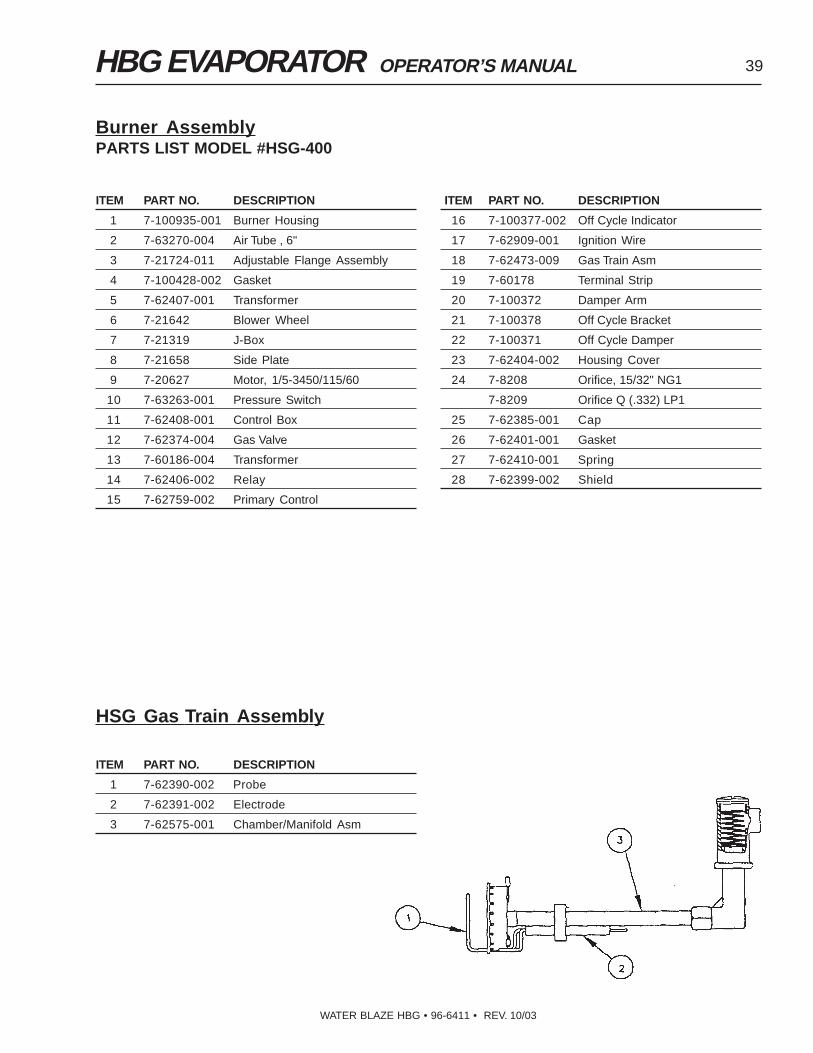
Burner Assembly, HBG-30MODEL #HSG-400 PART # 7-00046
REF1.25 .09
2.50
.06
.08
.75 .80
Sensor and Electrode Alignment
HBG EVAPORATOR OPERATOR’S MANUAL 39
WATER BLAZE HBG • 96-6411 • REV. 10/03
ITEM PART NO. DESCRIPTION
1 7-100935-001 Burner Housing
2 7-63270-004 Air Tube , 6"
3 7-21724-011 Adjustable Flange Assembly
4 7-100428-002 Gasket
5 7-62407-001 Transformer
6 7-21642 Blower Wheel
7 7-21319 J-Box
8 7-21658 Side Plate
9 7-20627 Motor, 1/5-3450/115/60
10 7-63263-001 Pressure Switch
11 7-62408-001 Control Box
12 7-62374-004 Gas Valve
13 7-60186-004 Transformer
14 7-62406-002 Relay
15 7-62759-002 Primary Control
Burner AssemblyPARTS LIST MODEL #HSG-400
ITEM PART NO. DESCRIPTION
16 7-100377-002 Off Cycle Indicator
17 7-62909-001 Ignition Wire
18 7-62473-009 Gas Train Asm
19 7-60178 Terminal Strip
20 7-100372 Damper Arm
21 7-100378 Off Cycle Bracket
22 7-100371 Off Cycle Damper
23 7-62404-002 Housing Cover
24 7-8208 Orifice, 15/32" NG1
7-8209 Orifice Q (.332) LP1
25 7-62385-001 Cap
26 7-62401-001 Gasket
27 7-62410-001 Spring
28 7-62399-002 Shield
ITEM PART NO. DESCRIPTION
1 7-62390-002 Probe
2 7-62391-002 Electrode
3 7-62575-001 Chamber/Manifold Asm
HSG Gas Train Assembly

40 HBG EVAPORATOR OPERATOR’S MANUAL
WATER BLAZE HBG • 96-6411 • REV. 10/03
TROUBLESHOOTING
MELBORP ESUACELBISSOP NOITULOS
T'NOWENIHCAMPUREWOP
deppirtrekaerB elcychctabteserdnarekaerbteseR.nottubTSR/1Fehtgnihsupybrellortnoc
etelpmocelcychctaB gnihsupybrellortnocelcychctabteseR.nottubTSR/1Feht
TONSEODTOLIP)51-GBH(THGIL
enilsagniriA .enilsagdeelB
erusserpsagwolrohgiH .rotalugerriatsujdA
ecifirotolipdekcolB .ecifironaelcroecalpeR
TUOSEOGTOLIPGNIRUDYLTNEUQERF
)51-GBH(YBDNATS
enilsagtolipninoitcirtseR .enilnaelC
erusserpsagwoL .rotalugererusserptsujdA
ecifirotolipdekcolB .ecifironaelcroecalpeR
TUOSEOGTOLIPEVLAVSAGNEHW
SNEPO)51-GBH(
enilsagtolipninoitcirtseR .ecifirotolipnaelC
erusserpsagwolrohgiH .erusserptsujdadnatseT
niamnehwporderusserpevissecxEsnepoevlavsag
.gnipipsagtelnifoezisesaercnI
SEODROTOMRENRUBNURTON
ffositnerrucroesuftuodenruB .ecalperdnaesufkcehC
roevitcefedtimilrotatsomrehTtesylreporpmi
.tatsomrehtteserdnatseT
evitcefedremrofsnartroyaleR .ecalperdnatseT
tuodenrubrotoM .ecalpeR
gniriwreporpmI .snoitcennocllakcehC
hctiwserutarepmethgihteserlaunaMdeppirtsi
teseR.knatforoolfnaelcdnaeparcS.xoblortnocfokcabnohcitws
nisitaolfhgiH.hgihootsileveldiuqiLnoitisoppu
rewolotknatmorfretawhguoneevomeR.renrubtratsernehttaolflevel
ROTOMRENRUBONTUBGNINNUR
EMALF
)51-GBH(tuotoliP .renrubtratseR
erusserpsagonrowolyreV .rotalugererusserptsujdA
wolsootgninnurrotoM .egatlovkcehC
RENRUBYSIONTROHSEMALF
woloottesrotalugererusserP .erusserpesaercnI
ediwootneporettuhsriA .rettuhsesolC
enilsagniporderusserphcumooT .ezisepipsagesaercnI
rotalugerevitcefeD .ecalpeR
EMALFWOLLEYGNOL hguonenepotonrettuhsriA .)01egapgnitteSriAees(rettuhsrianepO
deggolcleehwrewolbrosgnineporiA .naelC
sagtupnihcumooT .nwoderusserpsagnruT
EVLAVSAGNIAMESOLCTONSEOD
SPOTSREWOLBNEHW
evlavevitcefeD .evlavsagecalpeR
taesevlavnonoitcurtsbO .evlavsagecalpeR
TNEVROTALUGERSAGGNIKAEL
mgarhpaidnieloH .rotalugerecalpeR

HBG EVAPORATOR OPERATOR’S MANUAL 41
WATER BLAZE HBG • 96-6411 • REV. 10/03
TROUBLESHOOTING
MELBORP ESUACELBISSOP NOITULOS
TUHST'NOWRENRUBRETAWWOLTANWOD
krowtonseodtaolfretawwoL neht,ytiunitnocrofhctiwskcehC.ecalperrotsujda
ROPUTAEHT'NOWRETAWYLWOLSOOTPUSTAEH
knatroroolfnopudliubegdulS .knatfomottobmorfegdulseparcS
renrubrofylppussagtcerrocnI .dedeenfiteseR.dlofinamkcehceR
TRATST'NOWPMUPRIA tonhctiwsorcimpot,taolfgnoLhgihootretaW.dezigrene
rewolyllaunamrognitaropavepeeK.levelretaweht
wolootdetsujdagnittesrotalugerriA neewtebotrotalugerriatsujdaeR.isp001dna05
deggulpdionelospmupriA .tuonaelC
liocdionelospmupriaotegatlovoN .xoblacirtcelenigniriwkcehC.dedeensastrapecalpeR
liocdionelospmupriadaB .liocdionelosecalpeR
RETAWETSAWRIAMORFGNIGRAHCSID
TSUAHXEPMUP
erutpurmgarhpaidrofkcehC .ecalper,derutpurfI
tunmgarhpaidrofkcehC .tunnethgiT
NISELBBUBRIAESOHEGRAHCSID
gnibmulpnoitcusfosnoitcennockcehC .nethgiter,esoolfI
dlofinamekatninospmalcdnabkcehC .nethgiter,esoolfI
dlofinamekatnineewtebsgnir-okcehCspacdiulfdna
.nrowfisgnir-oecalpeR
tunmgarhpaidfossenthgitkcehC .tunnethgiT
TUORIASWOLBPMUPRIANEHWTSUAHXENIAM
REHTIENODELLATSEKORTS
evlavrojamniloopsnospucUkcehC .dedeenfiecalpeR
raewroftresnidnaetalpevlavkcehC .dedeenfiecalpeR
mgarhpaidnognir-odnaeveelskcehCdorgnitcennoc
.dedeenfiecalpeR
raewrofnotsipnosgnir-okcehC .dedeenfiecalpeR
.M.P.GEGRAHCSIDWOL ylppusriakcehC .isp001dna05neewtebottsujdA
esohegrahcsiddeggulprofkcehC .esohegrahcsidgulpnU
ebtsumtiflestiemirpotpmupehtroFtahtosnoitisoplacitrevanidetnuom
ytivargybkcehclliwsllabeht
.enihcamleveL
epipnoitcus-noitativacpmuprofkcehChgihfiregralromuminim"2/1ebdluohs
.depmupgnieberasdiulfytisocsivelbispalloc-nonebtsumesohnoitcuSmuucavhgihagnillupfoelbapac,epyt
.dezisrednufisesohecalpeR
dnasdlofinamekatninostniojllakcehCriaebtsumesehT.snoitcennocnoitcus
thgit
.snoitcennocdnastniojllanethgiT
gnitaesylreporpmirognikcitsrofkcehCsevlavkcehc
.sevlavkcehcnaelC
snurroetarhgihataselcycpmupfIraewrofsgnir-onotsipkcehc,yllacitarre
.dedeenfisgnir-oecalpeR

42 HBG EVAPORATOR OPERATOR’S MANUAL
WATER BLAZE HBG • 96-6411 • REV. 10/03
ETL Certified
LEDOM 51-GBH 03-GBH
ETARNOITAROPAVE )rH/retiL75-83(HPG51-01 )rH/retiL411-59(HPG03-52
ECRUOSYGRENE GPLrosaGlarutaN
EGASUYGRENE RH/UTB000,002 RH/UTB000,573
YTICAPACKNAT )sretiL562(snollaG07 )sretiL973(snollaG021
LAIRETAMKNAT LEETSDLIM sllaWeguaG"61/3,roolFetalP"8/3
LEETSSSELNIATS sllaWeguaG21,roolFetalP"4/1
NOITALUSNI detalusnIriA
THGIEW )gK255(.sbL512,1 )gK576(.sbL584,1
HxLxWSNOISNEMID"56x"5.87x"33
)mC561x991x48("07x"44x"09
)mC871x211x922(
STNEMERIUQERREWOP )llifotuacirtcelerofspma51(spmA3,HP1,V021
YTNARRAW straPraeY1 straPraeY1
SPECIFICATIONS
HBG COST FORMULAS
Propane conversion from gallons of propane to therms for use in chart below: 1 Therm = 1.0929 gallons of propane.Multiply the cost of 1 gallon of propane by 1.0929 to determine the propane cost per therm.Example: Propane = $1.50 gallon. Multiply 1.0929 (gallons of propane per therm) x $1.50 (cost of gallon ofpropane)= $1.6393 per therm.
LEDOM EGASULEUF ETARNOITAROPAVE
51-GBH RH/UTB000,002 ruohrepsnollag51
03-GBH RH/UTB000,573 ruohrepsnollag82
Constants:
1 cubic foot of natural gas = 1,000 BTU's 1 gallon of propane = 91,500 BTU's
1 gallon of propane = 0.915 therms 1 therm = 100 standard cubic feet of natural gas
1 therm = 100,000 BTU's
Operating Cost for Natural Gas:
Gas Cost (Cost per Gallon) = HBG Rating BTU's per Hour x Local Cost of Fuel per Therm
BTU's per Therm x HBG Evaporation Rate
Operating Cost for Electricity:
Electricity Cost (Cost per Gal) = Volts x Amps x Cost of Kilowatt Hour
1000 x HBG Evaporation Rate
Example for HBG-15: 200,000 BTU/Hr, 40¢/Therm, 120 Volts, 3 Amps, 6¢/KWH
Gas Cost (¢/Gal) = 200,000 x .40 = 5.3 ¢/Gal
100,000 x 15
Electricity Cost (¢/Gal) = 120 x 3 x .06 = .1¢/Gal
1000 x 15
Total Cost = 5.3¢ (gas) + .1¢ (elec) = 5.4¢/Gal

HBG EVAPORATOR OPERATOR’S MANUAL 43
WATER BLAZE HBG • 96-6411 • REV. 10/03
PREVENTATIVE MAINTENANCEThis evaporator was produced with the best available materials and quality craftsmanship. However, you as the ownerhave certain responsibilities for the correct care of the equipment. Attention to regular preventative maintenanceprocedures will assist in preserving the performance of your equipment. Contact your Landa dealer for maintenance.Regular preventative maintenance will add many hours to the life of your machine. Perform maintenance more oftenunder severe conditions.
ELUDEHCSECNANETNIAM
egdulStcepsnI yliaD
evomeR hctabetelpmochcaeretfA
leveLdiuqiLsehctiwS
tcepsnI yliaD
naelC ylkeeW
)s(knaTnaelCdnatcepsnI hctabetelpmochcaeretfA
rotoMrecudnItfarDetacirbuL yllaunna-imeS
sniFrecudnItfarDnaelC ylhtnoM
01-8neewtebHpretawetsaW yliaD
retliF/neercSretaWnaelC ylkeeW

HBG SERIES PRESSURE WASHER OPERATOR’S MANUAL 44
WATER BLAZE SYSTEMS
®
WATER BLAZE LIMITED NEW PRODUCT WARRANTYWATER TREATMENT SYSTEMS
WHAT THIS WARRANTY COVERSAll WATER BLAZE water treatment systems are warranted by WATER BLAZE to the original purchaser to be free from defectsin materials and workmanship under normal use, for the periods specified below. This Limited Warranty, subject to the exclu-sions shown below, is calculated from the date of the original purchase, and applies to the original components only. Any partsreplaced under this warranty will assume the remainder of the part’s warranty period. A 60 day grace period will be given forinstallation.
ONE YEAR PARTS AND 30 DAY LABOR WARRANTY:All components excluding normal wear items as described below.
WARRANTY PROVIDED BY OTHER MANUFACTURERS:Motors, which are warranted by their respective manufacturers, are serviced through these manufacturers’ local authorizedservice centers. WATER BLAZE cannot provide warranty on these items.
WHAT THIS WARRANTY DOES NOT COVERThis warranty does not cover the following items:
1. Normal wear items, such as seals, filters, gaskets, O-rings, packings, pistons, brushes, filtering media, ozone bulbs,sensors, UV scanners, oil-skimmer belt, impedance sensor.
2. Damage or malfunctions resulting from accidents, abuse, modifications, alterations, incorrect installation, improperservicing, failure to follow manufacturer’s maintenance instructions, or use of the equipment beyond its stated usagespecifications as contained in the operator’s manual.
3. Damage due to freezing, sludge build-up, chemical deterioration (oxidation, chloride or fluoride corrosion).4. Damage to components from fluctuations in electrical or water supply.5. Normal maintenance service, including adjustments.6. Transportation to service center, field labor charges, or freight damage.
WHAT YOU MUST DO TO OBTAIN WARRANTY SERVICEWhile not required for warranty service, we request that you register your WATER BLAZE Product by returning the completedregistration card. In order to obtain warranty service on items warranted by WATER BLAZE, you must return the product to yourAuthorized WATER BLAZE Dealer, freight prepaid, with proof of purchase, within the applicable warranty period. If the productis permanently installed, you must notify your Authorized WATER BLAZE Dealer of the defect. Your Authorized WATER BLAZEDealer will file a claim with WATER BLAZE, who must subsequently verify the defect. In most cases, the part must be returnedto WATER BLAZE freight prepaid with the claim. For warranty service on components warranted by other manufacturer’s, yourAuthorized WATER BLAZE Dealer can help you obtain warranty service through these manufacturers’ local authorized servicecenters.
LIMITATION OF LIABILITYWATER BLAZE’S liability for special, incidental, or consequential damages is expressly disclaimed. In no event shall WATERBLAZE’S liability exceed the purchase price of the product in question. WATER BLAZE makes every effort to ensure that allillustrations and specifications are correct, however, these do not imply a warranty that the product is merchantable or fit for aparticular purpose, or that the product will actually conform to the illustrations and specifications. THE WARRANTY CON-TAINED HEREIN IS IN LIEU OF ALL OTHER WARRANTIES, EXPRESS OR IMPLIED, INCLUDING ANY IMPLIED WAR-RANTY OF FITNESS FOR THE PARTICULAR PURPOSE, INCLUDING QUALITY OF WATER TREATMENT. WATER BLAZEdoes not authorize any other party, including authorized WATER BLAZE Dealers, to make any representation or promise onbehalf of WATER BLAZE, or to modify the terms, conditions, or limitations in any way. It is the buyer’s responsibility to ensure thatthe installation and use of WATER BLAZE products conforms to local codes. While WATER BLAZE attempts to assure that itsproducts meet national codes, it cannot be responsible for how the customer chooses to use or install the product.
WATER BLAZE HBG • 96-6411 • REV. 10/03


Form #96-6411 • Revised 10/03 • Printed in U.S.A.
WATER BLAZE SYSTEMS
®