operator's manual english - scanx scout
TRANSCRIPT

2
TABLE OF CONTENTS
FOREWORD
Section Page
General Safety . . . . . . . . . . . . . . . . . . . . . . . . . . . . . . . . . . 3
Important Information . . . . . . . . . . . . . . . . . . . . . . . . . . . . 6
Warranty . . . . . . . . . . . . . . . . . . . . . . . . . . . . . . . . . . . . . . 7
On-Line Warranty Registration . . . . . . . . . . . . . . . . . . . . . . . . 7
Introduction . . . . . . . . . . . . . . . . . . . . . . . . . . . . . . . . . . . . 8
Purpose of this Manual . . . . . . . . . . . . . . . . . . . . . . . . . . . . . 8
System Description . . . . . . . . . . . . . . . . . . . . . . . . . . . . . . . 9
Unpacking and Inspection . . . . . . . . . . . . . . . . . . . . . . . . . 10
Technical Data . . . . . . . . . . . . . . . . . . . . . . . . . . . . . . . . . 11
Computer System Requirements . . . . . . . . . . . . . . . . . . . . . . 16
Abbreviations . . . . . . . . . . . . . . . . . . . . . . . . . . . . . . . . . . 17
Controls and Indicators . . . . . . . . . . . . . . . . . . . . . . . . . . . 18
System Setup . . . . . . . . . . . . . . . . . . . . . . . . . . . . . . . . . . 20
Plate Care and Preparation . . . . . . . . . . . . . . . . . . . . . . . . . 22
Imaging Procedures . . . . . . . . . . . . . . . . . . . . . . . . . . . . . . 24
Powering Down the System . . . . . . . . . . . . . . . . . . . . . . . . . 27
Scheduled Maintenance . . . . . . . . . . . . . . . . . . . . . . . . . . . 27
Maintenance . . . . . . . . . . . . . . . . . . . . . . . . . . . . . . . . . . . 28
Troubleshooting . . . . . . . . . . . . . . . . . . . . . . . . . . . . . . . . 29
If You Need Assistance . . . . . . . . . . . . . . . . . . . . . . . . . . . . 31
Air Techniques and its ALLPRO Imaging division have prepared this document as a guide to the proper use of the ScanX Scout Computed Radiography System In-Line Erase .
Refer to the following companion documents as necessary:Document Part NumberImaging Plate Intensifier Screen Warning Instructions 73020Phosphor Storage Plate Instruction Sheet 73474

3
GENERAL SAFETY
The ScanX has been designed to minimize exposure of personnel to hazards . While the equipment is designed for safe operation, certain precautions must be observed . Use of the ScanX not in conformance with the instructions specified in this manual may result in permanent failure of the unit .
General.• Check with your dealer for packing material requirements if it is necessary to
return the product to the manufacturer . Correct packing guarantees optimal safety of the device during transport . Should it become necessary to return the device to the manufacturer during the warranty period, the manufacturer will not accept claims for damage arising from using incorrect packing materials .
• Before every use, the operator must check the functional safety and the condition of the device .
• The operator must be knowledgeable in the operation of the device .
UseofAccessoryEquipment.The use of ACCESSORY equipment not complying with the equivalent safety requirements of this equipment may lead to a reduced level of safety of the resulting system . Consideration relating to the choice shall include:
- use of the ACCESSORY in the patient vicinity .- evidence that the safety certification of the ACCESSORY has been performed
in accordance to the appropriate IEC 60601-1 and/or IEC 60601-1-1 harmonized national standard .
Use of ACCESSORIES or cables other than those specified or provided by the manufacturer may result in increased EMISSIONS or decreased IMMUNITY of the EQUIPMENT .
DoNotAttemptInternalService.The interior of each component of the ScanX System is only accessible by removing hardware with tools and should only be opened and serviced by an authorized dealer service technician .Contact your local ALLPRO Imaging authorized dealer for service . Failure to heed this directive may result in equipment damage and voiding the warranty .
ElectricalSafetyNotes.• The main power switch is the main power disconnect device .• Use only the line cord provided with the unit .• Use only grounded electrical connections .• To avoid risk of electric shock, fire, short-circuit or dangerous emissions,
never insert any metallic object into the equipment .• Only use connection cable(s) delivered with the device .• Check the device cables for possible damage before switching on .
Damaged cables, plugs and sockets must be replaced before use .• Never touch open supply outlets and patients simultaneously .• Do not locate unit where it could be sprayed with water, or in a damp environment .
4
GENERAL SAFETY
KnowledgeofWarningsandCautions.Users must exercise every precaution to ensure personnel safety, and be familiar with the warnings and cautions presented throughout this manual and summarized below . In this manual, the following definitions apply for all WARNINGS and CAUTION Statements:WARNINGS: Any operation, procedure or practice, which, if not strictly observed, may
result in injury or long-term health hazards to personnel.
CAUTIONS: Any operation, procedure or practice, which, if not strictly observed, may result in destruction of equipment or loss of effectiveness or damage to equipment and Phosphor Storage Plates (PSPs).
DANGER: Opening the ScanX by removing any covers or components makes the equipment into a Class III b Laser Product. [Class 3B Laser Product (IEC 60825)].
Warnings -Onlytrainedprofessionalsshouldusethisdevice.Federal law pro-hibits the sale of this device to individuals other than trained professionals . Use of this device, other than as described in this manual, may result in injury .TheScanXcontainsalaserandisaClass1[Class1(IEC60825)]LaserProduct.Use of controls or adjustments or performance of proce-dures other than those specified herein may result in hazardous radiation exposure . The laser is on only during an active scan .Only a trained technician from an authorized dealer shouldremoveacoverfromtheScanX.Direct eye contact with the output beam from the laser may cause serious damage and possible blindness .DonotopentheScanXtomaintainit.The ScanX contains no user ser-viceable parts . If there is a service problem, contact your authorized dealer .OperateScanXindryenvironment.To prevent fire or electrical shock, do not expose this appliance to rain or moisture .EquipmentDisposal.Disposal of Scanx units, including internal batteries, electronic circuitry and PSPs must be accomplished only at the appropriate facilities for recovery and recycling . Make sure to dispose of such items in accordance with current federal, national, state and local government rules and regulations .
Cautions -EMCComplianceRequirements. Use USB cables not exceeding 3m to connect between the computer and the scanner . Cable lengths greater than 3m may violate EMC compliance .Stacking or using the scanner adjacent to other equipment may violate EMC compliance and interfere with the scanner operation .DonotusedamagedPhosphorStoragePlates (PSPs). Damaged PSPs may not provide reliable diagnostic images .

5
Markings.The following terms or symbols are used on the equipment or in this manual to denote information of special importance:
DANGERAVOID DIRECT
EXPOSURE TO BEAM
LASER RADIATION WHEN OPEN
CAUTIONCLASS 1 LASER PRODUCT
CLASS 3B LASERRADIATION WHEN OPEN
AVOID EXPOSURE TO BEAM
CLASS IIIb LASER PRODUCT
COVER REMOVED MAKESTHIS DEVICE A
The ScanX is a Class I Laser Product [Class 1 Laser Product (IEC)]This warning label identifies the ScanX as such a product and describes the potential danger to humans in the event the product is opened during service. There is no laser radiation from this product when operated and maintained as instructed.The Laser Product Accession Number is 0212282-00
Alerts users to important Operating and Maintenance instructions. Read carefully to avoid any problems.
CLA
SSIFIED
Medical Electrical Equipmentwith respect to electrical shock, fire,
mechanical and other specified hazards only in accordance with
UL-60601-1, CAN/CSA C22.2 No.601.1 66CA
Warns users that uninsulated voltage within the unit may be of sufficient magnitude to cause electric shock.
Indicates that the unit conforms with WEEE Directive 2002/96/EC and must be disposed of only at the appropriate facilities for recovery and recycling.
GENERAL SAFETY
Cautions (Continued)-CompletelycleananderasePSPsbeforetakinganX-rayexposure.See the PLATE PREPARATION section of this manual . MinimizeexposinganX-rayexposedPSPtolight.Transfer the PSP into the Inlet slot quickly to minimize exposure to light .UsecareinhandlingPSPs-Avoidfingerprintsandscratching.Refer to the instructions provided with the PSP package for further information on handling .Useofothermanufacturer’simagingplates.Do not put PSPs designed for drum-type or other scanners in the ScanX . The hooks and/or frames on the ends or around these PSPs, or PSPs of different thickness (especially thicker ones) will damage the ScanX . PSPs from another manufacturer may be used as long as the specifications are the same as those for the ScanX PSPs .
Contraindications . None known .
EC REP Authorized Representative for Medical Device Directive
Indicates date of manufacture
Identifies the name of the manufacturer.
Indicates that the ScanX complies with the Medical Device Directive 93/42/EEC.

6
GeneralNotes. All instructions in this manual form an integral part of the unit . They must
be kept close to the unit and in readiness whenever required . Precise observance of these instructions is a pre-condition for use of the unit for the intended purpose and for its correct operation . This manual should be passed on to any future purchaser or operator .
Safety of the operator as well as trouble-free operation of the unit are only ensured if use is made of original equipment parts . Moreover, use may only be made of those accessories that are specified in the technical documentation or that have been expressly approved and released by the manufacturer for the intended purpose . The manufacturer cannot warranty for the safety or proper functioning of this unit in the case where parts or accessories are used that are not supplied by the manufacturer .
There is no guarantee against damage arising where parts or accessories are used that are not supplied by the manufacturer .
Observe the usage and storage conditions . Appliances which accumulate condensation or become wet through a change of
temperature may only be operated after they are fully dry again . The manufacturer regard themselves as being responsible for the equipment
with regard to safety, reliability and proper functioning only if assembly, resetting, changes or modifications and repairs have been carried out by an authorized dealer and if the equipment is used in conformity with the instructions contained in this manual .
The device conforms to the relevant safety standards valid at this time .
CorrectUsage Operation of the ScanX may only be carried out by suitably qualified
personnel . The ScanX is only to be used in the processing of exposed PSPs . If the device is stored in a cool environment and brought to a warmer
one, condensation can build up . Do not connect the device until it has warmed up to room temperature and is absolutely dry .
The immediate working area should be free of all possible interferences (e .g . strong magnetic fields), as these could affect the operation .
The ScanX may only be operated together with authorized software . Correct usage includes observing all adherence to the set-up, operation
and maintenance instructions . Any use, above and beyond that described in this manual as correct
usage, will invalidate the warranty .
IncorrectUsage Any use that is not described in this manual as correct usage is considered
as incorrect usage . The manufacturer is not to be held liable for any damage caused as a result of incorrect usage . The operator bears all risks .
IMPORTANT INFORMATION

7
WARRANTYWARRANTY
Quickly and easily register your new ScanX Scout scanner on-line . Just have your product model and serial numbers available . Then go to the ALLPRO Imaging web site, www .allproimaging .com, click the Warranty Registration link at the top of the page and complete the registration form . This on-line registration ensures a record for the warranty period and helps us keep you informed of product updates and other valuable information .
ON-LINE WARRANTY REGISTRATION
Warranty-ScanXEquipmentThe ScanX is warranted to be free from defects in material and workmanship from the date of installation for a period of one year . The ScanX is designed as a truly portable computed radiography system suited for use in remote field applications as well as in office environments .
If your ScanX cannot be repaired in the field and turns out to be defective due to faulty materials and/or workmanship within the warranty period, ALLPRO Imaging will arrange to replace the unit at its expense within two business days . ALLPRO Imaging will ship the Customer a replacement, factory refurbished ScanX . The Customer then returns (at ALLPRO Imaging’s expense) the malfunctioning system back to ALLPRO Imaging in the same shipping container .
This ScanX Swap Warranty coverage is valid in the US and Canada only and applies provided the product is handled properly for its intended use, in accordance with its operating instructions . This warranty does not apply to damage due to shipping, misuse, careless handling or repairs by non-authorized personnel .
Upon determination of eligibility by ALLPRO Imaging’s Technical Support personnel, the Customer must return the malfunctioning ScanX within 15 business days or Customer will be invoiced for the replacement ScanX . Any returned units become the property of ALLPRO Imaging . In case of replacement of the product, the Warranty Period will remain in effect for 6 months or for the remaining period of the original warranty; whichever term is longer .
The Warranty is void if installed or serviced by other than authorized service personnel . If unit fails, and the problem is determined to be caused by the lack of recommended scheduled maintenance as outlined in this Instruction Manual (i .e . worn Belt Drives or Brushes), this failure would not be covered . This warranty does not cover accessories .

8
This manual provides the information necessary for the setup, operation and routine care and maintenance of the ScanX Scout Computed Radiography Systems In-Line Erase . This manual is not to be used as a replacement for training in radiography .For information regarding the computer system and imaging software, refer to the appropriate documentation provided with your computer hardware and software .
PURPOSE OF THIS MANUAL
INTRODUCTION
Figure 1 . ScanX Scout Computed Radiography System In-Line Erase Model
Congratulations on your purchase of the ScanX Scout Computed Radiography System In-Line Erase, the latest portable imaging product from ALLPRO Imaging, a leading manufacturer of imaging systems for the medical, industrial and security markets . The system has been designed and manufactured using state-of-the-art technology to produce the lightest, most portable, rugged and dependable digital imaging system available . Designed and built exclusively for the demanding conditions encountered in portable radiography applications, the system is extremely easy to deploy producing excellent quality digital images in seconds . This efficiency coupled with repeatable consistent image quality provides results that allows the user to make critical decisions on the spot eliminating the need to return for retakes .The ScanX Scout is hereafter referred to as ScanX in this manual . Review and follow the guidelines included in this manual to ensure that your ScanX gives the highest level of service .

9
SYSTEM DESCRIPTION
GeneralThe ScanX is a self-contained computed radiography (CR) imaging scanner/eraser system that utilizes reusable photostimulable or Phosphor Storage Plates (PSP) in place of X-ray film to produce quality digital radiographs . The PSPs are durable and reusable thousands of times . Upon exposure to X-rays, the plate stores a latent image, which is scanned by the ScanX . After scanning, the image is processed via the user-supplied computer running authorized software and ready for viewing in seconds . In addition to immediate display of the resultant images, the software allows image enhancement processing, storage (hard drive or CD), and sharing/retrieval .
An additional feature of the ScanX includes a patented in-line plate erase function that removes the latent image from the plate immediately after scanning . This design provides an efficient one-operation scanning and erasing process leaving the user with a PSP ready for the next X-ray procedure .
The flexible and rugged design allows for the ScanX to be used on a counter top or for complete mobility inserted into either an optional hard or soft carrying case for easy and safe transport anywhere image scanning is required .
ScanXScoutFeatures
The only truly portable computed radiography system suited for the rigors of work in the field .
High-resolution images in seconds for critical decision on-the-spot .
Wire-free setup for tight access applications .
Share results anywhere, anytime .
Cushioned, lightweight extruded aluminum frame resists dents .
Sturdy, isolating/damping feet eliminate potential image quality issues due to vibration .
Patented, built-in eraser with manual or auto erase function .
Uses all brands of phosphor storage plates .
Accepts any brand of imaging plates up to 14” wide by any practical length, and custom shapes .
Works with a wide range of X-ray sources including gamma ray .
High resolution digital images .
Adjustable settings for optimum dynamic range .
Optional carrying options include a soft or hard case .
Operates in daylight .

10
UnpackingAs shown by Figure 2, the ScanX is shipped in a single carton containing the ScanX main assembly and associated accessory kit . Unpack each component of the ScanX and inspect for physical damage such as scratched panels, damaged connectors, etc . If any damage is noted, immediately notify your ALLPRO Imaging authorized dealer immediately so corrective action can be taken . Save all cartons and packing materials to protect the ScanX in the event that it is to be transported or shipped in the future .
IncludedSystemComponentsThe ScanX consists of the indicated main assembly and accessory kit as listed below . Verify that all listed items were received . If any item is missing, notify your dealer .
UNPACKING AND INSPECTION
Figure 2 . Typical ScanX Scout Packaging
System Components - ScanX Scout, P/N D5000-S
Quick Start Instructions D5431Q
Accessory Kit containing: D5493Dust Cover D5262Brush Kit D502710-Foot Power Cord 730966-Foot USB Cable D5226Accessory Literature Kit: D5493-LIT
Sample ScanX Cleaning Sheet Kit B2030CD Disk containing Drivers, Utilities and Operator's Manual D5435
ScanX Unit
Accessory Kit
Accessory Kit Contents
Accessory Literature Kit
10-Foot Power Cord
6-Foot USB Cable
aqtrg?jhsoNm?cTOQV
om?cTOQVLk
Brush Kit
ctrs?bnudq
oNm?cTQUQ
om?cTQTX
Dust Cover

11
TECHNICAL DATA
ElectricalRequirements:Supply Voltage: 100 to 240VAC, 50/60 Hz Supply Current: 2 .5 A MaximumLine Cord: North American style 10 foot long Hospital Grade power cord, P/N 61035 Country specific line cords are available
PhysicalProperties: Length Width HeightDimensions: 18 .0 inches 15 .5 inches 14 .0 inches (45 .72 cm) (39 .37 cm) (35 .56 cm)
Weight: 43 lbs . (19 .5 Kg)
EnvironmentalConditions:Unit in Operation
Temperature: 20 to 115°F (-7 to 46°C)Humidity: 5% to 95% (Non-condensing) Heat emission: <90W
Storage and Transport Temperature: -21 to 130°F (-29 to 55°C)Humidity: 5% - 95% (Non-condensing)
Note: Resolution of the ScanX is dependent on operating mode and specific imaging plate type used.
Resolution(LP/mm) Vertical Horizontal 3 .8 to 5 .0 3 .8 to 7
ComplianceData:Laser Classification: Class I Laser Product Compliance with FDA HHS 21 CFR 1040 .10 and IEC 60825-1Laser Product ReportAccession Number: 0212282-00
IEC60601-1Classification:Class 1, No Applied Parts, Transportable, Continuous Operation,Equipment not suitable for use in the presence of flammable anaesthetic mixture(s) . Protection against ingress of liquids -Ordinary
ElectromagneticInterference:Electromagnetic interference between the equipment and other devices can occur . Do not use the equipment in close conjunction with sensitive devices, or devices creating high electromagnetic disturbances .

12
TECHNICAL DATA
The following provides the EMC technical data used to show that each ScanX is designed and manufactured to meet the electromagnetic requirements of International standard IEC 60601-1-2 as shown below . The user should ensure that the ScanX unit is indeed used within this environment to ensure that the system will perform as intended .
IMPORTANT: Mobile RF communications equipment can effect medical electrical equipment.
Medical electrical equipment require special precautions regarding EMC and needs to be installed according to EMC information.
Guide and Declaration by Manufacturer - Electromagnetic Emissions
The ScanX is intended to be used within the electromagnetic environment specified below . The user of the ScanX should assure that it is used in such an environment .
Emissions test Compliance Electromagnetic Environment - Guide
RF emissions ClSPR 11
Group 1 The ScanX uses radio-electrical energy only for its internal subsystems . Therefore, it emits very low energy and is not likely to interfere with nearby electronic devices .
RF emissions ClSPR 11
Class A The ScanX can be used in all premises other than residential premises and premises connected directly to the public low-voltage power distribution network used for powering residential buildings .Harmonic emissions
EN 61000-3-2Class A
Voltage fluctuations/flicker EN 61000-3-3
Applicable

13
TECHNICAL DATA
Guide and Declaration by the Manufacturer - Electromagnetic Immunity
The ScanX is intended to be used within the electromagnetic environment specified below . The user of the ScanX should assure that it is used in such an environment .
Immunity Test IEC 60601 Test Level
Compliance Level
Electromagnetic Environment - Guide
Electrostatic Discharge (ESD) IEC 61000-4-2
± 6kV contact± 8kV air
± 6kV ± 8kV
Floors should be wood, concrete or ceramic tile . If floors are covered with synthetic material, the relative humidity should be at least 30% .
Electrical fast transient/burst IEC 61000-4-4
± 2 kV for power supply lines± 1 kV for Input/output lines
± 2kV ± 1kV
Mains power quality should be that of typical commercial or hospital environment .
SurgeIEC 61000-4-5
± 1 kV line(s) to line(s)± 2 kV line(s) to earth
± 1kV N/A
Mains power quality should be that of typical commercial or hospital environment .
Voltage dips, short interruptions and voltage variations on power supply input lines IEC 61000-4-11
<5% Ur (>95% dip in Ur) for 0 .5 cycle
<40% Ur (>60% dip in Ur) for 5 cycles
70% Ur (>30% dip in Ur) for 25 cycles
<5% Ur (>95% dip in Ur) for 5 s
<5% Ur - 10ms
<40% Ur - 100ms
70% Ur - 500ms
<5% Ur - 5 s
Mains power quality should be that of typical commercial or hospital environment .
If the user of the ScanX requires to continued operation during power mains interruptions in the main power supply, it is recommended that the ScanX be powered from an uninterruptible power supply or battery .
Power frequency (50/60Hz) magnetic fieldIEC 61000-4-8
3 A/m 3A/m Power frequency magnetic fields should be at levels characteristic of a typical location within a typical commercial or hospital environment .
Note: Ur is the a . c . mains voltage prior to application of the test level .

14
TECHNICAL DATA
Guide and Declaration by the Manufacturer - Electromagnetic Immunity
The ScanX is intended to be used in the electromagnetic environment specified below . The user of the ScanX should assure that it is used in such an environment .
Immunity Test
IEC 60601 Level
Compliance Level
Electromagnetic Environment - Guide
Portable and mobile RF communication equipment should be used no closer to any part of the ScanX, including cables, than the recommended separation distance calculated from the equation applicable to the frequency of the transmitter .
Recommended separation distance:
Conducted RF IEC 61000-4-6
3 Vrmsw 150 kHz to 80 MHz
3 V d=1,16 √P
Rediated RF IEC 61000-4-3
3V/m 80 MHz to 2 .5 GHz
3 V/m d=1,16 √P 80 MHz to 800 MHzd=2,33 √P 800 MHz to 2 .5 GHz
where P is the maximum output power of the transmitter in Watts (W) according to the transmitter manufacturer and d is the recommended separation distance in meters (m) .
Field strengths from fixed RF transmitters, as determined by an electromagnetic site survey, a should be less than the compliance level in each frequency b .Interference can occur nearby devices bearing the following symbol:
Note1: At 80 to 800 MHz, the higher frequency range applies .
Note2: Theseguidelines may not apply in all situations .Electromagnetic propagation is affected by absorption and reflection from structures, objects and people .
a . Field strengths from fixed transmitters, such as base stations for radio (cellular/cordless) telephone and land mobile radios, AM and FM radio broadcast, and TV broadcast can not be predicted theoretically with accuracy . To assess the electromagnet environment due to fixed RF transmitters, an electromagnetic site survey should be considered . If the measured field strength in the location in which the ScanX is used exceeds the applicable RF compliance level above, the ScanX should be observed to verify normal operation . If abnormal performance is observed, additional measures may be necessary, such as re-orienting or relocating the ScanX .
b. Over the frequency range 150 kHz to 80 MHz, field strengths should be less than [V1] V/m .

15
TECHNICAL DATA
Recommended separation distances between portable and mobile RF communication systems and the ScanX Computed Radiography System
In-Line Erase system
The ScanX is intended for use in an electromagnetic environment in which radiated RF interferences are controlled . The user of the ScanX can help prevent electromagnetic interference by maintaining a minimum distance between portable and mobile RF communications equipment (transmitters) and the ScanX such as recommended below, according to the maximum output power of the communications equipment .
Maximum assigned output power of the transmitter
W
Separation distance as a function of the transmitter's frequency
m150 kHz to 80 MHz 80 MHz to 800 MHz 800 MHz to 2.5 GHz
d=1,16 √P d=1,16 √P d=2,33 √P
0 .01 0 .116 0 .116 0 .233
0 .1 0 .366 0 .366 0 .736
1 1 .16 1 .16 2 .33
10 3 .66 3 .66 7 .36
100 11 .6 11 .6 23 .3
For transmitters rated at a maximum output power not listed above, the recommended separation distance (d) in meters (m) can be established by using the equation applicable to the frequency of the transmitter, where P is the maximum output power rating of the transmitter in Watts (W) according to the transmitter manufacturer .
Note1: At 80 to 800 MHz, the higher frequency range applies .
Note2: Theseguidelines may not apply in all situations .Electromagnetic propagation is affected by absorption and reflection from struc-tures, objects and people .
16
COMPUTER SYSTEM REQUIREMENTS
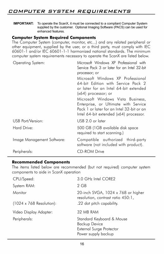
IMPORTANT: To operate the ScanX, it must be connected to a compliant Computer System supplied by the customer. Optional Imaging Software (PACS) can be used for enhanced features.
ComputerSystemRequiredComponentsThe Computer System (computer, monitor, etc . . .) and any related peripheral or other equipment, supplied by the user, or a third party, must comply with IEC 60601-1 and/or IEC 60601-1-1 harmonized national standards . The minimum computer system requirements necessary to operate the ScanX are listed below .
Operating System: Microsoft Windows XP Professional with Service Pack 3 or later for an Intel 32-bit processor; or
Microsoft Windows XP Professional 64-bit Edition with Service Pack 2 or later for an Intel 64-bit extended (x64) processor; or
Microsoft Windows Vista Business, Enterprise, or Ultimate with Service Pack 1 or later for an Intel 32-bit or an Intel 64-bit extended (x64) processor .
USB Port/Version: USB 2 .0 or later
Hard Drive: 500 GB (1GB available disk space required to start scanning .)
Image Management Software: Compatible authorized third-party software (not included with product) .
Peripherals: CD-ROM Drive
RecommendedComponentsThe items listed below are recommended (but not required) computer system components to aide in ScanX operation
CPU/Speed: 3 .0 GHz Intel CORE2
System RAM: 2 GB
Monitor 20-inch SVGA, 1024 x 768 or higher resolution, contrast ratio 450:1,
(1024 x 768 Resolution): .22 dot pitch capability .
Video Display Adapter: 32 MB RAM
Peripherals: Standard Keyboard & Mouse Backup Device External Surge Protector Power supply backup

17
System PropertiesSystemProperties.If unsure of the operating system version installed, check that it meets the necessary requirements by checking the System Properties window . This is done simply by right clicking the MyComputer icon . Selecting Properties from the menu list displays the System Properties window as shown . The installed operating system version is listed under the General tab . The System Properties window can also be opened from the Desktop Start button . Just press the Start button and select SettingsControlPanel and then click System icon .
COMPUTER SYSTEM REQUIREMENTS
ABBREVIATIONS
Abbreviations used in this manual are summarized below .
A ampere(s)AC alternating currentCD-ROM compact disk, read-only
memoryCFR Code of Federal
RegulationsCPU central processing unit
(your computer)cm centimeterGB gigabyte (230 109
bytes)GHz Gigahertz (109 of Hertz)H heightHz Hertz (cycles per second)IEC International Electro-
technical CommissionIMS Image Management
SoftwareIP imaging plate LED Light emitting diodeL lengthlbs poundslp/mm line pair per mm
lux a measure of light intensityMB megabytes
(220 106 bytes)mm millimeter (10-3 m)MONTH YYYY date
(Month, 4 digit year)Phosphor a luminescent materialPN part numberPSP photostimulable
phosphor plate (imaging plate)RAM random access memoryRH relative humiditySVGA Super Video Graphics
ArrayUSB Universal Serial BusUL Underwriters
LaboratoriesV VoltsW Watts, width °C degree Celsius°F degree Fahrenheit”, in inch

18
CONTROLS AND INDICATORS
PowerControlPanelControlandConnectionFunctions
Item Function
Main PowerSwitch (I/0)
A circuit breaker that controls the application of ScanX operating power and protects against shorts in the internal electrical circuits.
USB Type B Connector
Provides USB connection from the computer via the supplied USB Computer Connector Cable.
IEC Connector Provides connection of Mains outlet power via supplied line cord.
Figure 3 . Power Panel Control and Connection Locations
USB Connector, Type B
Main Power Switch (I/0)
IEC Connector
Figure 4 . Membrane Keypad and Indicator Locations
Scanner Track Status
Indicators
ERASER Switch
READY Switch
Eraser Status
IndicatorReady/Standby Status Indicator

19
CONTROLS AND INDICATORS
MembraneKeypadandIndicatorFunctions
Item Function
READY Switch
Toggles between the Standby and Ready mode as follows:
1. Press to switch from the Standby mode to the Ready mode.
2. Press and hold down for at least 2 seconds to switch to the Standby mode from the Ready mode.
Ready/Standby Status Indicator (Green LED)
Illuminates green to indicate that the ScanX is Ready for operation.When extinguished, it indicates that the ScanX is in the Standby mode.
ERASER Switch
Sets the erase function to operate in one of three modes:
1. Press the switch once to turn the erase function ON using one row of red LED erase lights.
2. Press the switch a second time to keep the erase function ON adding a second row of red LED erase lights.
3. Press the switch a third time to extinguish all red LED erase lights and turn the erase function completely OFF.
The switch has no effect once the plate scanning operation begins.
Note: When the Eraser Status Indicator displays a burst of approximately 5 quick flashes, it is alerting the user that the erase function is reduced due to a high temperature condition in the red LED erase light circuits. The user can continue scanning with the reduced function or wait for the full erase function to return when the temperature cools.
Eraser Status Indicator (Blue LED)
Displays the erase function status as set by the ERASER Switch:
1. Illuminates steady blue to indicate that the erase function is ON using red LED erase lights.
2. Extinguishes to indicate that the erase function is OFF and all red LED erase lights are extinguished.
Scanner Track Status Indicators (Bi-Color LEDs)
Displays the scanner operational status:
1. Illuminates green when the Scanner has been activated, indicating that a PSP can be fed into the ScanX.
2. Illuminates yellow, indicating the PSP has been sensed and the Scanner is transporting the PSP.

20
SYSTEM SETUP
Note: Authorized Imaging Software supplied by the dealer or other company, must be installed on the computer in order to operate the ScanX.
ScanXDriversandUtilitiesInstallationBefore connecting the ScanX to your computer or attempting to use it for the first time, run the Setup program on the ScanX Drivers and Utilities Disk included with the ScanX . Normally, this program runs automatically when the CD is inserted into the drive for the first time . If not, run the Setup program located in the root directory of the CD (typically D:\AutoRun.exe) .
ScanXInitialConnectionProcedureRefer to Figure 5 and perform the following procedure to connect the ScanX for operation to a computer for the first time .
1 . Make sure that the computer meets all requirements (see page 16) necessary to support ScanX operation . Set up the computer according to the manufacturer's recommendations .
2 . Verify that an authorized Imaging Software and the supplied USB drivers are installed properly on the computer .
3 . Connect the high speed USB cable between the USB Type B connector located on the ScanX panel and the USB Type A connector located on the computer . Note: Connect the line cord to the ScanX prior to plugging the line cord into
the Mains outlet.
4 . Connect the line cord between the Mains outlet and the IEC connector located on the ScanX panel .
5 . Turn ON the main power to the ScanX by placing the rocker switch on the Built-In Control/Connector panel to the ON (I) position . The scanner is now in the Standby mode .
6 . Switch the scanner from standby to ON by pressing the membrane READY switch ( ) located on the Membrane Keypad Panel on the top of the scanner . Verify that both the green and blue LED indicators above the READY and ERASER switches, respectively, illuminate .
7 . With both the ScanX and computer turned on, Windows detects the ScanX as a new USB Device and the Found New Hardware Wizard will appear .
Windows should automatically find the drivers installed from the ScanX Drivers and Utilities Disk .

21
SYSTEM SETUP
ScanXModelConnections(MainsACPower)Refer to Figure 5 and perform the following procedure to reconnect the ScanX to a previously initialized computer for normal operation using Mains AC power .
1 . Connect the high speed USB cable between the USB Type B connector on the ScanX panel and the USB Type A connector located on the computer .
Note: Connect the line cord to the ScanX prior to plugging the line cord into the Mains outlet.
2 . Connect the line cord between the Mains outlet and the IEC connector located on the ScanX panel .
Figure 5 . ScanX Connections
Note: The Main Power Switch is the Mains disconnect device.
From Mains Outlet
Line Cord
Type B USB Connector
IEC Connector
Type A USB Connector to
Computer
Main PowerSwitch (I/0)
22
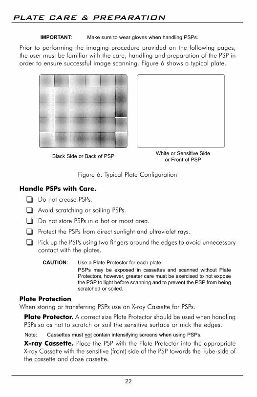
IMPORTANT: Make sure to wear gloves when handling PSPs.
Prior to performing the imaging procedure provided on the following pages, the user must be familiar with the care, handling and preparation of the PSP in order to ensure successful image scanning . Figure 6 shows a typical plate .
PLATE CARE & PREPARATION
Black Side or Back of PSP White or Sensitive Sideor Front of PSP
HandlePSPswithCare.
Do not crease PSPs .
Avoid scratching or soiling PSPs .
Do not store PSPs in a hot or moist area .
Protect the PSPs from direct sunlight and ultraviolet rays .
Pick up the PSPs using two fingers around the edges to avoid unnecessary contact with the plates .
CAUTION: Use a Plate Protector for each plate. PSPs may be exposed in cassettes and scanned without Plate
Protectors, however, greater care must be exercised to not expose the PSP to light before scanning and to prevent the PSP from being scratched or soiled.
PlateProtectionWhen storing or transferring PSPs use an X-ray Cassette for PSPs .
PlateProtector. A correct size Plate Protector should be used when handling PSPs so as not to scratch or soil the sensitive surface or nick the edges .
Note: Cassettes must not contain intensifying screens when using PSPs.
X-rayCassette. Place the PSP with the Plate Protector into the appropriate X-ray Cassette with the sensitive (front) side of the PSP towards the Tube-side of the cassette and close cassette .
Figure 6 . Typical Plate Configuration
23
PLATE CARE & PREPARATION
IMPORTANT: PSPs must always be erased prior to use.
Note: Use PSPs within 24 hours of last erasure. Repeat erasing process if PSPs have been stored longer than 24 hours.
ErasingPSPsEach PSP should be used (i .e . X-ray exposed and scanned) within 24 hours of erasure since natural radiation will add noise to the PSP . Erase PSPs by simply using the ScanX In-Line Erase Feature . Erasing of PSPs can be accomplished using one of two methods as follows:
Note: Both erasing methods will result in an erased PSP suitable for reuse. The user will not observe any difference in ScanX operation when using either method.
Method #1 Perform the Activate Scanner and the Scanning and Erasing Plates pro-
cedures on pages 24 and 25 . Except when performing step 4 of the Activate Scanner procedure, select the Erase option from the installed authorized imaging software to activate the ScanX . This method does not scan the plate and no image will be acquired .
Method #2 Perform the Activate Scanner and the Scanning and Erasing Plates
procedures on pages 24 and 25 . This method scans the plate and the imaging software may acquire a “junk image” (scanned latent plate image) that should be subsequently deleted from the imaging software .
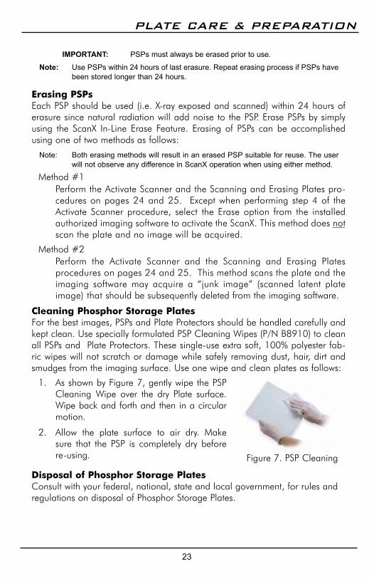
CleaningPhosphorStoragePlatesFor the best images, PSPs and Plate Protectors should be handled carefully and kept clean . Use specially formulated PSP Cleaning Wipes (P/N B8910) to clean all PSPs and Plate Protectors . These single-use extra soft, 100% polyester fab-ric wipes will not scratch or damage while safely removing dust, hair, dirt and smudges from the imaging surface . Use one wipe and clean plates as follows:
1 . As shown by Figure 7, gently wipe the PSP Cleaning Wipe over the dry Plate surface . Wipe back and forth and then in a circular motion .
2 . Allow the plate surface to air dry . Make sure that the PSP is completely dry before re-using .
DisposalofPhosphorStoragePlatesConsult with your federal, national, state and local government, for rules and regulations on disposal of Phosphor Storage Plates .
Figure 7 . PSP Cleaning

24
IMAGING PROCEDURES
IMPORTANT: Make sure that the x-ray imaging technique conforms to the intended application requirements/specifications.
Note: Cassettes must not contain intensifying screens when using PSPs.
TakeanX-RayImagePut an image on the PSP by performing the following procedure .
1 . Load cassette containing an erased PSP in a Plate Protector into the exposure device as previously done with film .
2 . Take the exposure .3 . Bring the closed cassette housing the X-ray exposed PSP containing the latent
image to the ScanX . The PSP is now ready to be scanned .
Place rocker switch to the
ON (I) position.
2
Figure 8 . ScanX Activation
3
4
Press the READY switch to turn ON the ScanX.
Verify that the READY and ERASER indicators illuminate
Verify that all 4 track status
indicators illuminate
6
5 Activate the scanner via the authorized Imaging Software
ActivateScannerRefer to Figure 8 and activate the ScanX by performing the following procedures .
1 . Make sure the associated ScanX is correctly connected as shown in Figure 5 .
2 . Place the power rocker switch to the ON (I) position .
3 . Switch the scanner from standby to ON by pressing the membrane READY switch located on the Membrane Keypad .
Note: Eraser mode is enabled as factory default. ScanX settings are thereafter retained as
set in last scan operation.
4 . Verify that both the green and blue LED indicators above the READY and ERASER switches illuminate . )
5 . Run the user-supplied authorized Imaging Software to activate the Scanner and to select the desired image type and resolution .
6 . Verify that the four Scanner track status indicators illuminate green when the Scanner has been activated, indicating that a PSP can be fed into the ScanX .

25
IMAGING PROCEDURES
Note: Only one exposed PSP can be fed into the ScanX at a time. The next PSP may be fed only after all four track status indicators change from yellow to green.
ScanningandErasingPlatesScan and erase an PSP in one operation as follows .
1 . Orient the cassette so that the Tube side is facing down and the hinge is away from you .
2 . Open the cassette and grasp the Plate Protector guide flaps to lift out the Plate Protector enclosed PSP . Pinch guide flaps between the thumb and index finger to prevent the PSP from sliding out of the Plate Protector . While minimiz-ing exposure to ambient light, move it to the ScanX inlet with the sensitive (front) side of PSP towards the ScanX .
3 . As shown by Figure 9, position the Plate Protector containing the PSP against the curved inlet, surface and hold it flush against the scanner inlet . A Plate Protector containing an exposed PSP narrower than 14 inches may be centered on the scanner inlet, making sure that it is aligned .
Figure 9 . Feeding an Imaging Plate
4 . Gently slide the PSP and Protector assembly into the scanning slot until the Protector is stopped by both guide flaps resting on the inlet ring which further aids in alignment .
5 . At this point, all four track lights will turn yellow, indicating the PSP has been sensed and the Scanner is transporting the PSP .
6 . Observe that a red glow emanates from the scanner exit slot .7 . Repeat steps 1 through 6 to process additional PSPs as necessary . Another PSP
may be fed into the ScanX when all four track indicator lights illuminate green .8 . Observe that the scanned PSP exits through the scanner arch . Since the
ScanX default operation mode is with the erase mode enabled (blue LED indicator below the ERASER switch is illuminated or flashing), the PSP is erased and ready for reuse for a new image .
9 . Observe that all transport status indicators illuminate green and the red glow from the exit slot extinguishes after the last PSP exits .
10 . Retrieve the processed (scanned and erased) PSP for reuse or storage . Make sure not to scratch the sensitive surface or nick the edges when removing from the scanner outlet .
11 . View and save the image using features of the user-supplied authorized Imaging Software .
Plate Protector
Guide Flaps
Scanner Inlet Ring
Imaging Plate (PSP)
Imaging Plate (PSP)
Plate Protector
Flap
IMPORTANT: Make sure that the plate protector does not get pulled into the ScanX transport along with the PSP plate.

26
EraseOnlyModeThe ScanX can be used to just erase PSPs . This is done simply by selecting the Erase option (instead of Scan) from the installed authorized imaging software when activating the ScanX . During the Erase Only mode just the in-line eraser is activated . The PSP is transported through the ScanX as a normal scan but is not scanned . No image is acquired and the PSP is erased and ready for reuse as necessary . See Erasing PSPs on page 23 .
IMAGING PROCEDURES
IMPORTANT: PSPs will not be erased after scanning when operating the ScanX with the eraser disabled. PSPs must always be erased prior to exposure to X-rays for new images.
ScanningPlateswithoutErasingThe ScanX can be operated with the in-line eraser feature turned off . When the eraser mode is disabled, the ScanX scans the same as when the eraser is enabled except that the PSPs are not erased after scanning . Scan an PSP without erasing the image by performing the following procedures .
1 . Activate the scanner by performing the procedures on previous page .Note: Always check that the eraser mode is disabled upon activation. The ScanX
defaults to the mode last used at power turn off.
Figure 10 . Eraser Disable
Press the ERASER switch twice to disable
the erase mode. 2
Verify that the ERASER indicator is
extinguished
3
2 . If necessary, disable the eraser mode of operation by pressing the ERASER switch located on the Membrane Keypad .
3 . Verify that the blue LED indicator located below the ERASER switch is extinguished to indicate that the Erase function is OFF . The PSP will notbe erased after scanning .
4 . Insert the PSP to be scanned into the ScanX by performing the Scanning and Erasing Plates procedures provided on the previous page .

27
POWERING DOWN THE SYSTEM
1 . Place the ScanX in the Standby mode by pressing and holding the membrane READY switch on the Membrane Keypad (approximately 2 seconds) until the green LED above the READY switch extinguishes .
2 . Verify that the READY indicator extinguishes .
3 . Remove the main power to the ScanX by placing the power rocker switch in the OFF (0) position .
IMPORTANT: Never power down the system during a scanning session.
ScanXModelsConnectedtoMainsACPowerThe ScanX is designed to be left on continuously during the active day . At the end of the day, or whenever desired, power down the system as shown by Figure 11:
Press & Hold (2 secs) READY switch to set ScanX in Standby.
1
Verify that the READY indicator
extinguishes
2
Figure 11 .Mains AC Powered ScanX Shut Down
Like all precision products, the ScanX requires a certain amount of care on a regularly scheduled basis . A well-organized maintenance program aids dependable equipment operation and reduces problems to a minimum . Routine checks help to detect general overall wear, and replacement of parts can often be made before a problem occurs . Adherence to the maintenance schedule will ensure that the ScanX Digital Imaging System will continue performing at its best with uninterrupted service .
Understanding this, we have established three basic maintenance kits that will help insure continuous operation of the ScanX Digital Imaging System . The kits and their associated parts number along with the recommended performance schedule are listed below .
SCHEDULED MAINTENANCE
IMPORTANT: All service requiring access to the interior of the ScanX must be performed only by an authorized dealer service technician with the proper training.
Place rocker switch to the OFF
(0) position.
3
Service Requirement Schedule Kit Part No.
Replace dust/debris brush on inlet ring assembly 1 year D5940
Replace four transport belt drive belt assemblies 4 years B7794

28
MAINTENANCE
MaintenanceProceduresThe ScanX is designed for many years of trouble-free operation . Maintenance as described herein is minimal .
IMPORTANT: Do not spray solvents or liquid directly on the scanner.
CleaningtheScanXTurn off the ScanX disconnect the line cord from the Mains wall outlet and disconnect the computer connection cable from the ScanX before cleaning . Wipe the outside surfaces with a soft paper towel dampened with a disinfectant solution or non-abrasive household cleaner . Be careful not to allow solvents TO RUN OR DRIP into the ScanX . This could cause damage to the ScanX . Allow to air dry before plugging in or turning back on .
CleaningthePlateTransportOver time, small debris and dust can accumulate in the plate transport mechanism causing a loss in image quality and possible damage to the PSPs .To ensure optimal performance of the ScanX, the plate transport should be cleaned at least once per week using a new ScanX Cleaning Sheet each time . Sample sheets are included with the ScanX and additional sheets can be purchased from your dealer .
PhosphorStoragePlates(PSPs)PSP's are subject to "wear" on the black side during normal handling and use . They can appear scratched, while the sensitive blue or white side remains relatively "smooth" . This scratched look on the black side has absolutely no effect on the quality of the image and should be expected under normal conditions . If the phosphor side is scratched make sure the plates are being handled properly and not being dragged from the ScanX tray area or other surfaces that could cause scratching of the plate . Make sure to review the Plate Care and Preparation information provided on page 22 of this manual .

29
TROUBLESHOOTING
Trouble Possible Cause Corrective Action1 No power/No green
light on membrane switch
• Not plugged in.
• No power at Mains Outlet
• The ScanX has not been turned on.
• Defective power supply
• Check that the line cord is firmly plugged in.
• Make sure outlet is grounded and has power.
• Make sure that the Main Power switch is set to ON.
• Call your authorized dealer.
2 Green, Blue or Yellow indicator light does not work.
• Defective light or circuitry. • Call your authorized dealer.
3 Imaging Software does not recognize the ScanX when selected.
• Inadequate Computer System.
• The ScanX has not been turned on.
• The computer connection cable is loose or defective.
• The computer does not recognize that the ScanX is connected.
• ScanX hardware problem. • ScanX Driver CD not run.
• Verify Computer System requirements (Page 16).
• Make sure that the READY switch is set to ON and the green indicator light is illuminated.
• Reconnect the cable. Check for tightness. Replace if necessary.
• Verify that the Setup program was correctly installed (Page 20).
• Call your authorized dealer.• Call your authorized dealer.
4 Plate does not scan properly.
• The PSP was not pushed far enough into the ScanX.
• Worn transport belt or belt driver.
• Check the plate protector tabs and fully feed the PSP into the ScanX.
• Replace defective transport belt or belt driver.
5 No image appears after scanning.
Important: Do not allow the PSP to be exposed to light between taking an X-ray and scanning with the ScanX.
• The PSP fed backwards (printed side towards ScanX).
• The PSP was erased prior to scanning.
• Hardware failure.• X-ray source failed or low
exposure.
• Quickly re-feed the plate with the printed side out. If a substandard image results, retake image.
• Feed the PSPs into the scanner immediately and quickly after removal from the cassette.
• Call your authorized dealer.• Call your authorized dealer..

30
TROUBLESHOOTING
Trouble Possible Cause Corrective Action6 Image is too dark. • PSP has been overexposed • Use software to adjust
brightness. If this is not possible, retake image with proper (lower) exposure and a newly erased PSP.
• Make sure intensifying screens are removed.
7 Image appears skewed on monitor.
• PSP was fed skewed.
• Worn transport belt or belt driver.
• When inserting PSP into feed slot, be sure to “feel” for resistance of light seal brush, align PSP, and then push down uniformly on top edge of PSP.
• Check the plate protector tabs.• Replace defective transport
belt or belt driver.
8 Image contains ghost images or shadows.
• PSP was not completely erased prior to use.
• Imaging Plate was exposed with the back fac-ing the tubehead.
• PSP has been stored too long in cassette.
• Partial erasure of the image due to exposure to light during handling of the PSP
• Make sure the ScanX is operating with both eras-er strips turned on (blue LED indicator below the ERASER switch is flashing).
• Make sure the plates are inserted properly into the barrier envelope or cassette with the proper orientation to the X-ray source.
• Do not store PSPs in cassettes for more than 24 hours.
• Do not leave exposed PSPs in well lit areas. Transfer PSPs from their protective cassettes to the ScanX within one hour of exposure.
• Make sure red erasing light eminates from both sides of the ring.
9 Image shows artifacts or white or black lines.
• The PSP surface is not clean and has dirt, stains or scratches on it.
• ScanX plate transport path may contain an obstruction, debris or dust.
• Clean the PSP with PSP wipes (P/N B8910).
• Make sure to handle plates properly.
• Do not reuse the PSP if scratched or stained.
• Clean transport path using a ScanX Cleaning Sheet (P/N B2010 or B2020).

31
IF YOU NEED ASSISTANCE
ALLPRO Imaging ScanX systems are designed and manufactured to high standards . They are easy to install and use and typically deliver high-quality performance . If any difficulties are encountered with this product, please contact ALLPRO Imaging Technical Support as follows:
1-800-247-8324 Monday through Friday 8:30 a .m . – 5:00 p .m . Eastern Time
or
1-800-822-2899 Monday through Friday 8:30 a .m . – 5:00 p .m . Pacific Time .
For additional information, please contact your authorized dealer or visit our web site, www.allproimaging.com
EC REPMedical Device Safety ServiceSchiffgraben 41 30175 Hannover, Germany
Air Techniques, Inc., Allpro Imaging1295 Walt Whitman Road Melville, New York 11747 USA
