operator's manual - ba lm en 43340210 -...
TRANSCRIPT
www.HATZ-DIESEL.com
Hatz Diesel
CREATINGPOWERSOLUTIONS.
OPERATOR’S MANUALDiesel engine
2-4L41C | 2-4M41 | 2-4M41Z | 4L42C | 4M42


Table of contents
1 Notices ............................................................................................................. 5
2 General information ........................................................................................ 6
3 Safety ............................................................................................................... 73.1 General information .......................................................................................... 73.1.1 Intended use and foreseeable misuse .............................................................. 73.1.2 Machine user or machine manufacturer obligations ......................................... 83.1.3 Representation of safety notes ......................................................................... 93.1.4 Meaning of safety symbols ............................................................................... 103.2 Safety notes ...................................................................................................... 113.2.1 Operational safety ............................................................................................. 113.2.2 Machine-specific safety instructions for operation ............................................ 143.2.3 Machine-specific safety instructions for maintenance work .............................. 163.2.4 Electrical equipment .......................................................................................... 183.3 Labels ............................................................................................................... 19
4 Technical data ................................................................................................. 224.1 Engine ............................................................................................................... 224.2 Fuel ................................................................................................................... 234.3 Engine oil .......................................................................................................... 24
5 Engine design ................................................................................................. 25
6 Transport, assembly and commissioning .................................................... 316.1 Transport ........................................................................................................... 316.2 Assembly instructions ....................................................................................... 316.3 Preparations for commissioning ........................................................................ 32
7 Operation and use .......................................................................................... 337.1 Safety notes ...................................................................................................... 337.2 Performing tests ................................................................................................ 337.3 Start preparation ............................................................................................... 347.3.1 Pumping fuel with the manual lever .................................................................. 347.3.2 Pumping fuel with the manual fuel pump .......................................................... 357.4 Setting the speed control .................................................................................. 377.5 Starting the engine ............................................................................................ 377.5.1 Starting the engine with crankhandle ................................................................ 387.5.2 Starting the engine with an electric starter ........................................................ 447.6 Switching off the engine .................................................................................... 477.6.1 Switching off the engine (mechanical) .............................................................. 487.6.2 Switching off the engine (electrical) .................................................................. 497.7 Refueling ........................................................................................................... 507.8 Checking the water separator ........................................................................... 517.9 Checking the oil level and adding oil if necessary ............................................ 53
2-4L41C, 2-4M41, 2-4M41Z, 4L42C, 4M42 Table of contents
HATZ Operator's Manual 3
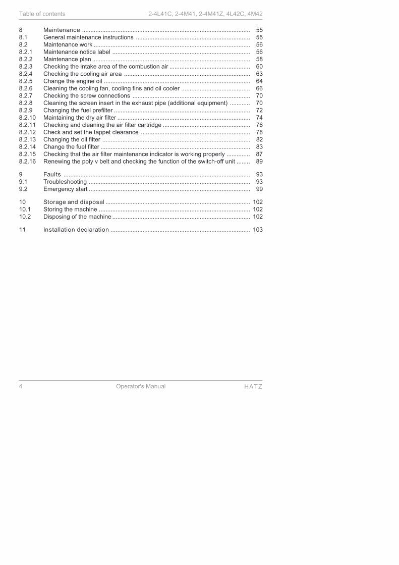
8 Maintenance .................................................................................................... 558.1 General maintenance instructions .................................................................... 558.2 Maintenance work ............................................................................................. 568.2.1 Maintenance notice label .................................................................................. 568.2.2 Maintenance plan .............................................................................................. 588.2.3 Checking the intake area of the combustion air ................................................ 608.2.4 Checking the cooling air area ........................................................................... 638.2.5 Change the engine oil ....................................................................................... 648.2.6 Cleaning the cooling fan, cooling fins and oil cooler ......................................... 668.2.7 Checking the screw connections ...................................................................... 708.2.8 Cleaning the screen insert in the exhaust pipe (additional equipment) ............ 708.2.9 Changing the fuel prefilter ................................................................................. 728.2.10 Maintaining the dry air filter ............................................................................... 748.2.11 Checking and cleaning the air filter cartridge .................................................... 768.2.12 Check and set the tappet clearance ................................................................. 788.2.13 Changing the oil filter ........................................................................................ 828.2.14 Change the fuel filter ......................................................................................... 838.2.15 Checking that the air filter maintenance indicator is working properly .............. 878.2.16 Renewing the poly v belt and checking the function of the switch-off unit ........ 89
9 Faults ............................................................................................................... 939.1 Troubleshooting ................................................................................................ 939.2 Emergency start ................................................................................................ 99
10 Storage and disposal ...................................................................................... 10210.1 Storing the machine .......................................................................................... 10210.2 Disposing of the machine .................................................................................. 102
11 Installation declaration ................................................................................... 103
Table of contents 2-4L41C, 2-4M41, 2-4M41Z, 4L42C, 4M42
4 Operator's Manual HATZ
1 Notices
Contact data
© 2012Motorenfabrik HATZErnst-Hatz-Straße 1694099 RuhstorfGermany
Tel. +49 (0)8531 319-0
Fax +49 (0)8531 319-418
www.hatz-diesel.com
All rights reserved!
Copyright
The copyright for this Operator's Manual rests entirely with MotorenfabrikHATZ, Ruhstorf.
This Operator's Manual may only be copied or distributed if written approvalhas been received. This also applies to the copying or distribution of ex-cerpts of the Operator's Manual. The same conditions apply to distribution ofthe Operator's Manual to third parties in digital form.
Original Operator's Manual
This Operator's Manual was translated into multiple languages.
The German version is the original Operator's Manual. All other languageversions are translations of the original Operator's Manual.
2-4L41C, 2-4M41, 2-4M41Z, 4L42C, 4M42 Notices
HATZ Operator's Manual 5
2 General information
Information on the document
This Operator's Manual was created with due care. It is exclusively intendedto offer a technical description of the machine and to provide instructions oncommissioning, operating and maintaining the machine. When operating themachine, the applicable standards and legal regulations as well as any in-house regulations apply.
Before commissioning, during operation and before maintenance work is be-gun on the machine, read the Operator's Manual carefully and keep it closeby for ready access.
Machine
This Operator's Manual describes the following machine.
Machine name HATZ diesel engine
Type number 2-4L41C 2-4M41 2-4M41Z 4M42 4L42C
Customer service
Have service work performed by qualified technicians only. We recommendthat you work with one of the more than 500 HATZ service stations.Trainedspecialists there will repair your machine with Hatz original spare parts andwith HATZ tools. The global HATZ service network is at your disposal to ad-vise you and supply you with spare parts. For the address of the Hatz serv-ice station nearest you, please see the directory enclosed or visit the inter-net at: www.hatz-diesel.com
Problems may occur if unsuitable spare parts are installed. We cannot ac-cept responsibility for damage and secondary damage that result from this.
We therefore recommend the use of Hatz original spare parts. These partsare manufactured according to strict Hatz specifications and achieve maxi-mum operational reliability through their perfect fit and functionality. The or-der number can be found in the enclosed spare parts list or on the internetat: www.hatz-diesel.com
Exclusion of liability
The manufacturer cannot be held responsible for personal injury, damage toproperty, or damage to the machine itself caused by improper use, foreseea-ble misuse, or failure to follow or adequately follow the safety measures andprocedures described in this Operator's Manual. This also applies tochanges made to the machine and use of unsuitable spare parts.
Modifications, which serve the technical improvements, are reserved.
General information 2-4L41C, 2-4M41, 2-4M41Z, 4L42C, 4M42
6 Operator's Manual HATZ

3 Safety
3.1 General information
Introduction
This chapter contains the information you need to work safely with this ma-chine.
To prevent accidents and damage to the machine, it is imperative that thesesafety instructions be followed.
Read this chapter carefully before beginning work.
3.1.1 Intended use and foreseeable misuse
Intended use
The machine described in this Operator's Manual fulfills the following func-tions:
▪ Diesel engine intended for installation in a machine or for assembly withother machines to form a machine. See the chapter 11 Installation decla-ration, page 103.
This engine is intended exclusively for the purpose specified and tested bythe manufacturer of the machine into which the engine is installed.
Any other use is not intended and therefore not permitted. Violations com-promise the safety of the personnel working with the machine. Responsibilityis not accepted by Motorenfabrik HATZ for damage resulting from this situa-tion.
The operational safety of the machine is only guaranteed if it is used as in-tended.
Use according to the intended purpose also includes observance of the in-structions in this Operator's Manual.
Foreseeable misuse
The following is considered to be foreseeable misuse:
▪ Any use that varies from or extends beyond the uses specified above.
▪ Failure to comply with the instructions in this Operator's Manual.
▪ Failure to comply with the safety instructions.
▪ Failure to immediately eliminate malfunctions that impact safety beforecontinuing work with the machine (working with the machine when it is notin perfect condition, either functionally or in terms of safety).
▪ Failure to perform the necessary inspection and maintenance work.
▪ Any unauthorized modification of or removal of safety equipment.
▪ Use of spare parts and accessories that are unsuitable or have not beenapproved by HATZ.
▪ Operation in flammable or hazardous environments.
▪ Operation in closed-off or poorly ventilated rooms.
2-4L41C, 2-4M41, 2-4M41Z, 4L42C, 4M42 Safety
HATZ Operator's Manual 7

▪ Installation of the machine in moving equipment (e.g. vehicles, trailers) orin closed rooms without additional measures to handle supply air, extractair, and exhaust gas.
▪ Improper operation at variance with DIN 6271 and DIN ISO 8528 (climate,load, safety).
Residual risks
Residual risks result during daily use and in association with maintenancework.
These residual risks will be pointed out in chapter 3.2.2 Machine-specificsafety instructions for operation, page 14 and in chapter 3.2.3 Machine-specific safety instructions for maintenance work, page 16 as well as in thefurther contents of the manual, directly in front of the descriptions or operat-ing instructions concerned.
3.1.2 Machine user or machine manufacturer obligations
Machine manufacturer obligations
If you have an engine that is not yet installed in a machine, it is imperativethat you follow the Assembly Instructions for HATZ Diesel Engines be-fore installing the engine. These assembly instructions contain important in-formation on how to safely install the engine and are available at your near-est HATZ service station.
It is prohibited to start the engine before it is fully installed.
In addition, please note that it is prohibited to start up the machine before ithas been determined that the machine into which this engine is installed ful-fills all safety-related requirements and legal regulations.
User obligations
The user is obligated to only operate the machine while it is in perfect condi-tion. The user must check the condition of the machine before using it andensure that any defects are eliminated before it is taken into service. Run-ning the machine while identified defects exist is not permitted. The usermust also ensure that the information contained in the Operator's Manualhas been read and understood.
Obligations of the operating and maintenance personnel
Personnel assigned with operating and maintaining the machine must haveread and understood the Operator's Manual or must be able to demonstratethe necessary qualifications for working with this equipment, acquired intraining/instructional courses. No one may work with the machine without thenecessary qualifications, even if for just a brief period.
All work performed on the machine must be in compliance with the informa-tion provided in the Operator's Manual.
Safety 2-4L41C, 2-4M41, 2-4M41Z, 4L42C, 4M42
8 Operator's Manual HATZ

Storing the Operator's Manual
This Operator's Manual is an integral component of the machine (also whenbeing sold). It must be stored in the direct vicinity of the machine and be ac-cessible to personnel at all times.
3.1.3 Representation of safety notes
Overview
This machine has been designed and built according to state-of-the-art tech-nology and the recognized safety standards. Despite these precautions,risks exist when operating the machine and during maintenance work.
These risks are identified in this manual by means of safety notes.
The safety notes precede the related description or operating step.
Structure of the safety notes
The safety notes consist of:
▪ Warning symbol
▪ Signal word
▪ Description of danger
▪ Possible consequences
▪ Preventative measures
General danger symbol
The general danger symbol is used to identify the danger of personal injury.
Signal words
Signal words identify the magnitude of the risk and the seriousness of thepossible injuries:
Danger symbol/signal word
Meaning
DANGERThis signal word is used to indicate imminentlydangerous situations which, if not avoided, willlead to serious injury or death.
WARNINGThis signal word is used to indicate potentiallydangerous situations which, if not avoided, maylead to serious injury or death.
CAUTIONThis signal word is used to indicate potentiallydangerous situations which, if not avoided, maylead to minor or moderate injury.
2-4L41C, 2-4M41, 2-4M41Z, 4L42C, 4M42 Safety
HATZ Operator's Manual 9

Danger symbol/signal word
Meaning
CAUTIONThis signal word, without a danger symbol, isused to indicate the risk of property damage.
NOTICEThis signal word indicates additional useful infor-mation, such as operating tips and cross referen-ces.
3.1.4 Meaning of safety symbols
Explanation of symbols
The following table describes the meanings of the safety symbols used inthis Operator's Manual.
Symbol Meaning
Smoking, fire and open flames are prohibited.
Warning of personal injury!
Warning of hot surfaces!
Warning of flammable substances!
Warning of explosive substances!
Warning of toxic engine exhaust!
Warning of corrosive substances!
Safety 2-4L41C, 2-4M41, 2-4M41Z, 4L42C, 4M42
10 Operator's Manual HATZ

Symbol Meaning
Warning of heavy loads!
Warning of environmental damage!
Comply with the Operator's Manual or additional documenta-tion from other manufacturers or the user.
iAdditional information that is useful to the reader.
3.2 Safety notes
3.2.1 Operational safety
Introduction
This chapter contains all of the important safety instructions for personal pro-tection and for safe and reliable operation. Additional, task-related safety in-structions can be found at the beginning of each chapter.
DANGER
Danger to life, danger of injury, or danger of property dam-age due to failure to comply with the Operator's Manual andthe safety instructions contained therein.
▪ As the user of the machine, you must ensure that all peopleworking on the machine are familiar with the contents of thisOperator's Manual.
▪ Before working on the machine, read this Operator's Manualcarefully, paying special attention to the safety notes.
▪ Fulfill all required safety conditions before working on themachine.
▪ Follow all general safety instructions as well as the specifictask-related safety instructions contained in the individualchapters.
2-4L41C, 2-4M41, 2-4M41Z, 4L42C, 4M42 Safety
HATZ Operator's Manual 11

Using the machine
▪ Only operate the machine for the purposes described in the chapter 3.1.1Intended use and foreseeable misuse, page 7.
Compliance with other regulations
▪ Adhere to the applicable accident prevention regulations of the trade asso-ciations.
▪ Comply with the regulations concerning the minimum safety and health re-quirements for the use of work equipment by workers at work.
▪ In addition, local safety, accident prevention and environmental regula-tions also apply when operating the machine.
Operating personnel
▪ The machine may only be operated by qualified personnel. The personnelmust have read and understood this Operator's Manual or must be able todemonstrate the necessary qualifications for working with this equipment,acquired in training/instructional courses.
▪ The operating personnel must not be under the influence of drugs, medi-cation or alcohol.
Personal protective equipment
During operation and maintenance of the machine, personal protectiveequipment must be available and must be used if necessary. The requiredpersonal protective equipment is specified in the description of the operatingsteps.
Personal protectiveequipment
Pictogram Function
Safety shoes Safety shoes offer protectionagainst:
▪ Slipping
▪ Falling objects
Hearing protection Hearing protection offers protec-tion against ear injuries due toexcessive and constant noise.
Safety gloves Safety gloves protect the handsagainst injury, e.g. from batteryacid.
Safety 2-4L41C, 2-4M41, 2-4M41Z, 4L42C, 4M42
12 Operator's Manual HATZ

Personal protectiveequipment
Pictogram Function
Safety goggles(with side protection)
Safety goggles protect the eyesfrom flying objects (e.g. dustparticles, spraying liquids,spraying acid).
Working clothes Wear close-fitting clothing. How-ever, it must not restrict thewearer's freedom of movement.
Warning labels and information signs on the machine
The warning and notice labels on the machine must be followed (see thechapter 3.3 Labels, page 19).
The warning and notice labels must be kept legible and must be replaced ifnecessary. For this purpose, contact your nearest HATZ service station.
Maintenance work
Maintenance work that goes beyond the scope described in this manualmust only be performed by qualified technicians (see the chapter 2 Generalinformation, page 6).
Independent maintenance work and constructional changes to the machine,especially to the safety equipment, are not permitted.
Safety equipment
Safety equipment must not be modified and must not be rendered ineffectiveduring normal operation.
General safety instructions
DANGER
Danger to life and danger of injury due to failure to followthe warnings on the machine and in the Operator's Manual.
▪ Heed the warnings on the machine and in the Operator'sManual.
2-4L41C, 2-4M41, 2-4M41Z, 4L42C, 4M42 Safety
HATZ Operator's Manual 13

WARNING
Danger of injury and danger of incorrect operation due toinadequate personnel qualifications.
▪ The personnel must have read and understood this Opera-tor's Manual or must be able to demonstrate the necessaryqualifications for working with this equipment, acquired intraining/instructional courses.
▪ Only qualified personnel is permitted to operate and main-tain this machine.
▪ Failure to comply will cause the warranty to be void.
WARNING
Danger of injury from the failure to follow the operating in-structions and from performing unauthorized tasks on themachine.
▪ Follow all instructions.
▪ Do not perform activities that are not authorized. Contactproperly trained personnel if necessary.
CAUTION
Danger of injury from overloading the body.
Lifting the machine to transport it or to move it to another loca-tion can lead to injuries (of the back, for example).
▪ Only lift the machine with a hoist (see the chapter 6.1 Trans-port, page 31).
3.2.2 Machine-specific safety instructions for operation
Introduction
The machine can pose residual risks during operation. To eliminate theserisks, all persons working on the machine must follow the general and ma-chine-specific safety instructions.
If you have an engine that is not yet installed in a machine, it is imperativethat you follow the Assembly Instructions for HATZ Diesel Engines be-fore installing the engine.
These assembly instructions contain important information on safe installa-tion.
If the engine is installed in a machine or assembled with other machines toform a machine, it is prohibited to start the engine before it has been deter-mined that the newly created machine fulfills all safety-related requirementsand applicable legal regulations.
Safety 2-4L41C, 2-4M41, 2-4M41Z, 4L42C, 4M42
14 Operator's Manual HATZ

Safe operation
▪ Before switching on the machine, ensure that no one can be injured whenthe machine is started up.
▪ During machine operation, ensure that unauthorized persons do not haveaccess to the area in which the machine has an impact.
▪ Parts of the exhaust gas system and the surface of the engine become hotduring operation. Risk of injury from touching hot parts! Let the engine coolbefore maintenance.
▪ Do not refuel during operation.
Faults
▪ Immediately eliminate faults that compromise safety.
▪ Switch off the machine and do not take into service again until all faultshave been eliminated.
Safety instructions for operation
DANGER
Danger to life from inhaling exhaust gases.
Toxic engine exhaust gases can lead to loss of consciousnessand even death in closed-off and poorly ventilated rooms.
▪ Never operate the machine in closed-off or poorly ventilatedrooms.
▪ Do not breathe in the exhaust gases.
DANGER
Fire hazard from fuel.
Leaked or spilled fuel can ignite on hot engine parts and causeserious burn injuries.
▪ Only refuel when the engine is switched off.
▪ Never refuel in the vicinity of open flames or sparks that cancause ignition.
▪ Do not smoke.
▪ Do not spill fuel.
2-4L41C, 2-4M41, 2-4M41Z, 4L42C, 4M42 Safety
HATZ Operator's Manual 15
CAUTION
Danger of injury from defective crankhandle.
A damaged or broken handle bar can cause injuries. A worncranking shaft can slip out of the starting mechanism when start-ing and also cause injuries.
▪ Check the crankhandle for a broken handle bar, worn crank-ing shaft, etc.; replace if necessary.
3.2.3 Machine-specific safety instructions for maintenance work
Introduction
The machine can pose residual risks during maintenance. To eliminatethese risks, all persons working on the machine must follow the general andmachine-specific safety instructions.
Maintenance intervals
▪ Strictly adhere to the maintenance intervals.
▪ Check the safety equipment regularly to ensure it is in good condition andfunctioning properly.
▪ Check connections, cables and fasteners regularly to ensure they are ingood condition.
Maintenance work
Maintenance work that goes beyond the scope described in this manualmust only be performed by qualified technicians. We recommend that youwork with one of the more than 500 HATZ service stations.
Replacing parts
▪ When replacing defective components, we recommend that you use gen-uine HATZ original spare parts (see the chapter 2 General information,page 6).
▪ When disposing of parts that can no longer be used, do so in accordancewith local environmental regulations or send them to a recycling center.
Measures following maintenance and troubleshooting
▪ Securely reconnect loose electrical connections; check that the electricalcomponents and equipment are functioning properly.
▪ Check the entire machine for foreign bodies; remove any foreign bodies.
Safety 2-4L41C, 2-4M41, 2-4M41Z, 4L42C, 4M42
16 Operator's Manual HATZ

Safety instructions for maintenance work
DANGER
Danger of explosion from flammable cleaning agents.
Cleaning with benzene is an explosion hazard. It is highly flam-mable, can become electrostatically charged and can generatean explosive gas-air mixture.
▪ Use halogen-free, cold cleaners with a high flashpoint forcleaning.
WARNING
Danger of injury from compressed air and dust particles.
Eye injuries may occur when cleaning with compressed air.
▪ Wear safety goggles.
CAUTION
Danger of injury if maintenance instructions are not fol-lowed.
▪ Only perform maintenance when the engine is switched off.
▪ For engines with an electric starter: Disconnect the negative battery terminal.Protect the starting key against unauthorized access.
CAUTION
Danger of burns.
There is a danger of burns when working on a hot engine.
▪ Let the engine cool before maintenance.
2-4L41C, 2-4M41, 2-4M41Z, 4L42C, 4M42 Safety
HATZ Operator's Manual 17

3.2.4 Electrical equipment
Safety notes
DANGER
Danger to life, danger of injury or danger of property dam-age due to incorrect use of batteries.
▪ Do not place tools on the battery.
▪ Before performing work on the electrical equipment, alwaysdisconnect the negative terminal of the battery.
▪ Never swap the positive (+) and negative (–) battery termi-nals.
▪ When installing the battery, first connect the positive cableand then the negative cable.
▪ When removing the battery, first disconnect the negativecable and then the positive cable.
▪ It is imperative that you prevent short circuits and mass con-tact of current-carrying cables.
▪ If faults occur, check the cable connections for good con-tact.
DANGER
Danger of explosion from flammable substances.
There is a danger of explosion from flammable gases.
▪ Keep batteries away from open flames and incendiarysparks.
▪ Do not smoke when working with batteries.
CAUTION
Danger of chemical burns
Chemical burns can occur when using batteries for the electricaloperation.
▪ Protect your eyes, skin, and clothing from corrosive batteryacid.
▪ Immediately rinse areas affected by splashed acid with clearwater and consult a physician if necessary.
Safety 2-4L41C, 2-4M41, 2-4M41Z, 4L42C, 4M42
18 Operator's Manual HATZ

NOTICE
▪ The necessary wiring diagrams are included with the ma-chine if it is equipped with electrical equipment. Additionalwiring diagrams can be requested when needed.
▪ We cannot be held liable for electrical equipment that is notdesigned according to HATZ wiring diagrams.
▪ Promptly replace faulty indicator lamps.
▪ Do not pull out the starting key during operation.
▪ Do not disconnect the battery while the machine is running. Resulting volt-age peaks could destroy the electronic components.
▪ When performing a manual emergency start, leave the (possibly depleted)battery connected.
▪ When cleaning, do no spray the electrical equipment components with awater jet or high pressure cleaner.
▪ When performing welding work on the machine, disconnect the batteryand place the ground clamp of the welding equipment as close as possibleto the welding area. Disconnect the plug-in connection to the voltage regu-lator.
3.3 Labels
Overview
The following labels are found on the machine:
▪ Engine type plate
▪ Warning labels and information signs on the engine
▪ Warning labels and information signs on the crankhandle
Engine type plate
➀➁➂➃
2-4L41C, 2-4M41, 2-4M41Z, 4L42C, 4M42 Safety
HATZ Operator's Manual 19

The engine type plate is located on the crankcase or sound protection hoodand contains the following engine information:
1 Number of the engine family or the EU approval (for engines with ex-haust certificate only)
2 Engine type, customer specification and setting of pumping start (°crankshaft before top dead center)
3 Engine serial number
4 Max. engine speed (rpm)
5 Model year
6 Displacement (liters) and inspection requirement for special settings
7 Injection pump effective stroke (mm) and engine capacity (kW)
8 “Constant speed only” (for engines with EPA/CARB exhaust certificateonly)
9 “Variable speed” (for engines with EPA/CARB exhaust certificate only)
The following data must always be specified for requests and spare part or-ders
2 Engine type and customer specification
3 Engine serial number
4 Max. engine speed (rpm)
Warning labels and information signs on the engine
Label Meaning
maxOIL
Maintenance instructions (see thechapter 8.1 General maintenance in-structions, page 55)
Safety 2-4L41C, 2-4M41, 2-4M41Z, 4L42C, 4M42
20 Operator's Manual HATZ

Label Meaning
0000 036 144
CAUTION!Damage from inadequate enginecooling.
▪ Only run the engine when all cov-ers are installed.
BIODIESEL
052 356 02
Refuel with diesel fuel only. Specifi-cation, see the chapter 4.2 Fuel,page 23
Do not use bio diesel.
Warning labels and information signs on the crankhandle
Label Meaning
0000 038 928 01
Hold the handle bar so that it cannottwist, and quickly turn the crank sothat continuous traction between theengine and crank is ensured, seethe chapter 7.5.1 Starting the enginewith crankhandle, page 38.
2-4L41C, 2-4M41, 2-4M41Z, 4L42C, 4M42 Safety
HATZ Operator's Manual 21
4 Technical data
4.1 Engine
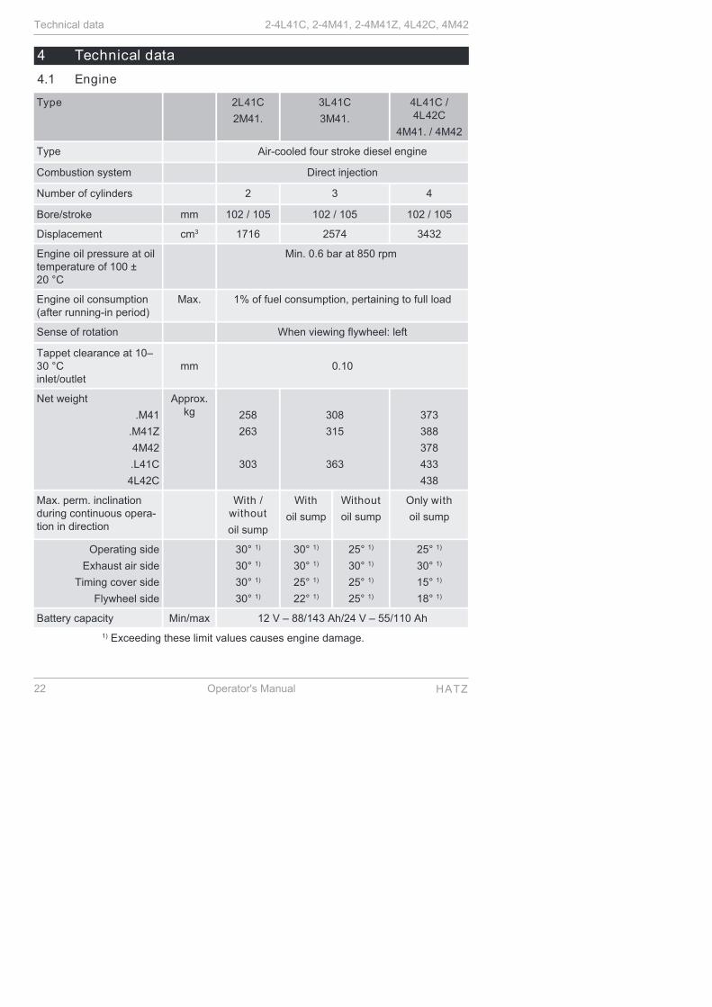
Type 2L41C
2M41.
3L41C
3M41.
4L41C /4L42C
4M41. / 4M42
Type Air-cooled four stroke diesel engine
Combustion system Direct injection
Number of cylinders 2 3 4
Bore/stroke mm 102 / 105 102 / 105 102 / 105
Displacement cm3 1716 2574 3432
Engine oil pressure at oiltemperature of 100 ±20 °C
Min. 0.6 bar at 850 rpm
Engine oil consumption(after running-in period)
Max. 1% of fuel consumption, pertaining to full load
Sense of rotation When viewing flywheel: left
Tappet clearance at 10–30 °Cinlet/outlet
mm 0.10
Net weight
.M41
.M41Z
4M42
.L41C
4L42C
Approx.kg
258
263
303
308
315
363
373
388
378
433
438
Max. perm. inclinationduring continuous opera-tion in direction
With /without
oil sump
With
oil sump
Without
oil sump
Only with
oil sump
Operating side
Exhaust air side
Timing cover side
Flywheel side
30° 1)
30° 1)
30° 1)
30° 1)
30° 1)
30° 1)
25° 1)
22° 1)
25° 1)
30° 1)
25° 1)
25° 1)
25° 1)
30° 1)
15° 1)
18° 1)
Battery capacity Min/max 12 V – 88/143 Ah/24 V – 55/110 Ah
1) Exceeding these limit values causes engine damage.
Technical data 2-4L41C, 2-4M41, 2-4M41Z, 4L42C, 4M42
22 Operator's Manual HATZ

Engine oil capacities and dipstick equipment
Type Oil sump Engine oil capacity2)
liters
Mark on the dip-stick
2L41C
2M41Z
With
Without
7.5
4.5
C
A
2M41 With
Without
8.5
5.5
C
A
3L41C
3M41Z
With
Without
10.5
8.0
D
A
3M41 With
Without
11.0
8.5
D
A
4L41C
4L42C
4M41Z
With
Without
13.0
–
D
–
4M41
4M42
With
Without
14.0
–
D
–
2) These values are approximations only. The max. mark on the dipstick isdecisive in any case (see the chapter 7.9 Checking the oil level and addingoil if necessary, page 53).
4.2 Fuel
Fuel type
All types of diesel fuel that meet the minimum requirements of the followingspecifications are suitable:
▪ EN 590 or
▪ BS 2869 A1 / A2 or
▪ ASTM D 975- 1D / 2D
CAUTION
Danger of engine damage from low quality fuel.
The use of fuel that does not meet the specifications can lead toengine damage.
▪ The use of fuel that does not meet specifications requiresapproval by Motorenfabrik HATZ (main plant).
Winter fuel
When outside temperatures drop below 0 °C, use winter fuel or mix in petro-leum in advance:
2-4L41C, 2-4M41, 2-4M41Z, 4L42C, 4M42 Technical data
HATZ Operator's Manual 23

Lowest ambient tempera-ture at start [°C]
Percentage of petroleum [%] for
Summer fuel Winter fuel
0 to -10
-10 to -15
-15 to -20
-20 to -30
20
30
50
‑
‑‑
20
50
4.3 Engine oil
Oil quality
All oil brands that meet at least one of the following specifications are suita-ble:
▪ ACEA – B2 / E2 or better
▪ API – CD / CE / CF / CF-4 / CG-4 or better
If engine oils of a low quality standard are used, the oil change interval mustbe reduced from 250 to 150 or from 500 to 250 operating hours dependingon the engine specification.
Oil viscosity
-40
-30
-20
-10
0
10
20
30
40
50
104
86
68
50
32
14
-4
-22
-40
OIL: S AE...°C°F
5W
/30
5W
/40
10W
/40
10W
/30
15W
/40
30 4
0
122
10W
Choose the recommended viscosity based on the type of start (recoil, crankhandle or electric) and on the engine temperature at which the engine will beoperated.
CAUTION
Engine damage from unsuitable engine oil.
Unsuitable engine oil considerably reduces engine service life. Only use engine oil that fulfills the specifications stipulatedabove.
Technical data 2-4L41C, 2-4M41, 2-4M41Z, 4L42C, 4M42
24 Operator's Manual HATZ

5 Engine design
Engine 2-4L41C
Encapsulated model "Silent Pack"
Pos. Designation
1 Access cap for fuel feed pump
2 Oil filling opening and dipstick
3 Type plate
4 Speed control lever
5 Oil filter
6 Exhaust silencer (encapsulated)
7 Cover for air guide housing (access to cooling fan belt)
8 Engine brackets
9 Oil drain screw
10 Cover plate on operating side
11 Side wall
12 Exhaust air duct
13 Capsule hood
2-4L41C, 2-4M41, 2-4M41Z, 4L42C, 4M42 Engine design
HATZ Operator's Manual 25

Pos. Designation
14 Retractable lifting eye, max. load 5000 N
15 Capsule intake shaft
16 Intake opening for combustion air
17 Fuel feed line with fuel prefilter
18 Fuel return line
19 Cover plate on exhaust side
20 Central connector for electrical equipment
21 Battery connections
22 Powerbox
23 Electrical maintenance switch for air filter
Engine 4L42C
Encapsulated model "Silent Pack"
Pos. Designation
1 Electronic control unit
2 Oil filling opening and dipstick
3 Type plate
Engine design 2-4L41C, 2-4M41, 2-4M41Z, 4L42C, 4M42
26 Operator's Manual HATZ
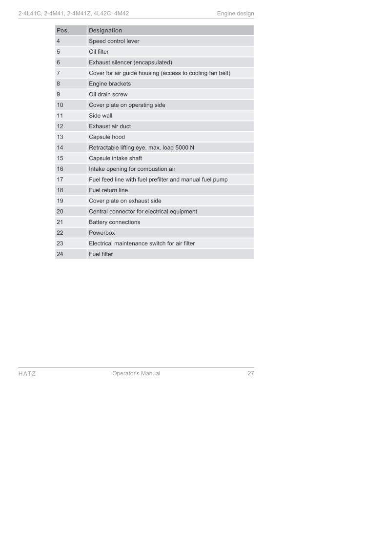
Pos. Designation
4 Speed control lever
5 Oil filter
6 Exhaust silencer (encapsulated)
7 Cover for air guide housing (access to cooling fan belt)
8 Engine brackets
9 Oil drain screw
10 Cover plate on operating side
11 Side wall
12 Exhaust air duct
13 Capsule hood
14 Retractable lifting eye, max. load 5000 N
15 Capsule intake shaft
16 Intake opening for combustion air
17 Fuel feed line with fuel prefilter and manual fuel pump
18 Fuel return line
19 Cover plate on exhaust side
20 Central connector for electrical equipment
21 Battery connections
22 Powerbox
23 Electrical maintenance switch for air filter
24 Fuel filter
2-4L41C, 2-4M41, 2-4M41Z, 4L42C, 4M42 Engine design
HATZ Operator's Manual 27

Engine 2-4M41, 2-4M41Z
Standard model
Pos. Designation
1 Oil filling opening and dipstick
2 Side trim panel
3 Intake opening for combustion air
4 Cooling fan belt
5 Cooling fan with installed three phase alternator
6 1/2-inch square socket for turning the engine
7 Oil drain screw
8 Speed control lever
9 Oil filter
10 Oil drain screw (on oil sump)
11 Cooling air guide for oil cooler
12 Access cap for fuel feed pump
13 Cylinder head cover
14 Air filter housing cover
15 Lifting eye, max. load 5000 N
Engine design 2-4L41C, 2-4M41, 2-4M41Z, 4L42C, 4M42
28 Operator's Manual HATZ

Pos. Designation
16 Fuel return line
17 Fuel feed line with fuel prefilter
18 Type plate
19 Silencer
20 Central connector for electrical equipment
21 Battery connections
22 Powerbox
23 Electrical maintenance switch for air filter
Engine 4M42
Standard model
Pos. Designation
1 Oil filling opening and dipstick
2 Side trim panel
3 Intake opening for combustion air
4 Cooling fan belt
5 Cooling fan with installed three phase alternator
2-4L41C, 2-4M41, 2-4M41Z, 4L42C, 4M42 Engine design
HATZ Operator's Manual 29
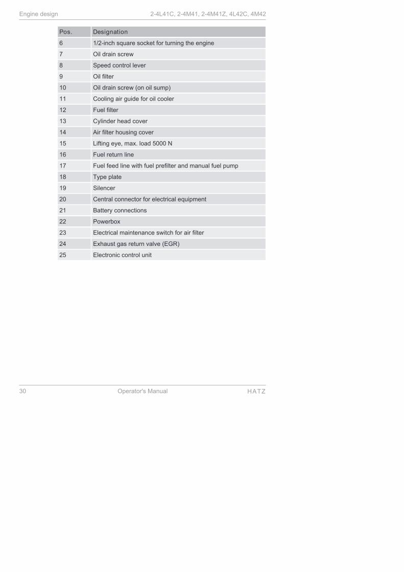
Pos. Designation
6 1/2-inch square socket for turning the engine
7 Oil drain screw
8 Speed control lever
9 Oil filter
10 Oil drain screw (on oil sump)
11 Cooling air guide for oil cooler
12 Fuel filter
13 Cylinder head cover
14 Air filter housing cover
15 Lifting eye, max. load 5000 N
16 Fuel return line
17 Fuel feed line with fuel prefilter and manual fuel pump
18 Type plate
19 Silencer
20 Central connector for electrical equipment
21 Battery connections
22 Powerbox
23 Electrical maintenance switch for air filter
24 Exhaust gas return valve (EGR)
25 Electronic control unit
Engine design 2-4L41C, 2-4M41, 2-4M41Z, 4L42C, 4M42
30 Operator's Manual HATZ

6 Transport, assembly and commissioning
6.1 Transport
Safety notes
CAUTION
Danger of injury from overloading the body.
Lifting the machine to transport it or to move it to another loca-tion can lead to injuries (of the back, for example).
▪ Only lift the machine with a hoist.
CAUTION
Only use lifting lugs for transporting the engine.
Do not use for lifting the entire machine.
NOTICE
Danger of environmental damage from leaking fluid.
If the machine is tilted, engine oil and diesel fuel can run out.
▪ Only transport the machine in an upright position.
Transport conditions
▪ Only lift the engine by the standard fitted lifting lugs.
▪ When transporting the machine, follow the safety instructions.
▪ When transporting, follow the applicable safety and accident preventionregulations of the trade associations.
▪ After delivery, check the machine for completeness and transport damage.
▪ Only transport the machine when it is switched off and has cooled down.
▪ If you have questions on transporting the machine, please contact yournearest HATZ service station. For contact data, see the chapter 1 "Noti-ces", page 5 or www.hatz-diesel.com.
6.2 Assembly instructions
Assembly notes
HATZ diesel engines are efficient, robust and long-lived. Therefore, they areusually installed in machines that are used for commercial purposes.
The machine manufacturer must follow the applicable regulations regardingmachine safety – the engine is a part of a machine.
2-4L41C, 2-4M41, 2-4M41Z, 4L42C, 4M42 Transport, assembly and commissioning
HATZ Operator's Manual 31
Depending on the use and installation of the engine, it may be necessary forthe machine manufacturer and machine user to install safety equipment toprevent inappropriate use. Note the following:
▪ Parts of the exhaust gas system and the engine surface become hot dur-ing operation and should not be touched until they cool down after the en-gine is switched off.
▪ Incorrect cable connections and incorrect operation of the electrical equip-ment can lead to sparking and must be avoided.
▪ After the engine is installed in the machine, rotating parts must be protect-ed against contact. HATZ safety equipment is available for the belt drive of the cooling fan andalternator.
▪ Comply with all notice and warning labels on the engine and keep them ina legible condition. If a label should become detached or be difficult toread, it must be replaced promptly. For this purpose, contact your nearestHATZ service station.
▪ Any improper modification of the engine results in a loss of liability cover-age for resulting damage.
Only regular maintenance, as specified in this Operator's Manual, will main-tain the operating readiness of the engine.
The assembly instructions contain important information on how to safely as-semble the engine. They are available from any Hatz service station.
If you have any questions, please contact your nearest HATZ service sta-tion before commissioning the engine.
6.3 Preparations for commissioning▪ Check the delivered parts for completeness, damage and other noticeable
issues.
▪ Ensure that the setup location is adequately ventilated.
DANGER
Danger to life from inhaling exhaust gases.
Toxic engine exhaust gases can lead to loss of consciousnessand even death in closed-off and poorly ventilated rooms.
▪ Never operate the machine in closed-off or poorly ventilatedrooms.
▪ Do not breathe in the exhaust gases.
Transport, assembly and commissioning 2-4L41C, 2-4M41, 2-4M41Z, 4L42C, 4M42
32 Operator's Manual HATZ

7 Operation and use
7.1 Safety notes
NOTICE
Comply with the safety chapter!
Follow the basic safety instructions in the chapter 3 Safety,page 7.
WARNING
Danger of injury from damage and defects on the machine.
▪ Do not take the machine into service if damage has been lo-calized and identified.
▪ Replace faulty components.
WARNING
Danger of injury from the failure to follow the operating in-structions and from performing unauthorized tasks on themachine.
▪ Define the responsibilities of the personnel taking the ma-chine into service.
▪ Replace faulty machine parts immediately.
▪ Check the installation conditions when the machine is firsttaken into service and after the machine has been inactivefor a lengthy period.
CAUTION
Danger of engine damage from low load operation.
Operating the engine at no load or at very low load for an ex-tended period can impair the running characteristics of the en-gine.
▪ Make sure that the engine load is at least 15 %.
▪ Before switching off the engine following low load operation,briefly operate it at a considerably higher load.
7.2 Performing tests
Before starting
Before starting the engine, several tests need to be performed to ensure themachine is working properly.
2-4L41C, 2-4M41, 2-4M41Z, 4L42C, 4M42 Operation and use
HATZ Operator's Manual 33

Procedure
Step Test
1 The machine is standing securely and on a level surface.
2 The installation location is adequately ventilated.
3 There is a sufficient amount of fuel in the fuel tank (see the chap-ter 4.2 Fuel, page 23).
4 There is a sufficient amount of engine oil in the engine housing(see the chapter 4.3 Engine oil, page 24).
5 For hand start:
▪ Crankhandle in functional condition.
▪ Sliding area between crankhandle and guide sleeve lightlygreased.
6 No persons are located in the danger zone of the engine or ma-chine.
7 All safety equipment is in place.
7.3 Start preparation
Procedure
Step Activity
1 Before the first start and with an empty fuel system:
▪ Pump the fuel with the manual lever (see the chapter 7.3.1Pumping fuel with the manual lever, page 34)
or
▪ Pump the fuel with the manual fuel pump (see the chapter7.3.2 Pumping fuel with the manual fuel pump, page 35)
7.3.1 Pumping fuel with the manual lever
Requirements
Pre-pumping of fuel with the manual lever of the fuel feed pump is necessaryin the following situations:
▪ Engine shuts down due to empty fuel tank
▪ at first filling of the fuel tank
▪ after changing the fuel filter
Operation and use 2-4L41C, 2-4M41, 2-4M41Z, 4L42C, 4M42
34 Operator's Manual HATZ

Overview
Pos. Designation
1 Manual lever (fuel feed pump)
2 Return line
Procedure
Step Activity
1 Fill with fuel if necessary.
2 Remove the access cap for the fuel feed pump.
3 Actuate the manual lever (1) on the fuel feed pump until the fuelaudibly flows back into the fuel tank through the return line (2).
4 Install the access cap again.
7.3.2 Pumping fuel with the manual fuel pump
Requirements
Pre-pumping of fuel with the manual fuel pump is necessary in the followingsituations:
▪ Engine shuts down due to empty fuel tank
▪ at first filling of the fuel tank
▪ after changing the fuel filter
2-4L41C, 2-4M41, 2-4M41Z, 4L42C, 4M42 Operation and use
HATZ Operator's Manual 35

Model with manual fuel pump
Only for 4L42C and 4M42
23
Pos. Designation
1 Bleed screw
2 Filter
3 Rubber ball
Procedure
Step Activity
1 If there is air in the fuel system:
Fill with fuel if necessary.
2 Place a suitable container under the filter (2) to collect emergingfuel.
3 Open the bleed screw (1) by approx. one turn.
4 Squeeze and release the rubber ball (3) repeatedly until fuelemerges from the bleed screw (1).
5 Close the bleed screw (1) and then activate the rubber ball twomore times.
Operation and use 2-4L41C, 2-4M41, 2-4M41Z, 4L42C, 4M42
36 Operator's Manual HATZ

7.4 Setting the speed control
Overview
½
Procedure
Step Activity
1 Depending on the situation, place the speed control lev-er in either the "1/2" or "Start" position.
NOTICE
iA lower speed setting will cause less exhaust smoke when start-ing.
7.5 Starting the engine
Starting options
The standard equipment of the engine is an electric start mechanism. Ahand starter can be installed as an option.
If possible, separate the engine from the machine being driven by uncou-pling it. Always switch the machine into idle mode.
2-4L41C, 2-4M41, 2-4M41Z, 4L42C, 4M42 Operation and use
HATZ Operator's Manual 37
Safety notes
DANGER
Danger to life from inhaling exhaust gases.
Toxic engine exhaust gases can lead to loss of consciousnessand even death in closed-off and poorly ventilated rooms.
▪ Never operate the machine in closed-off or poorly ventilatedrooms.
▪ Do not breathe in the exhaust gases.
CAUTION
Danger of injury from defective crankhandle.
A damaged or broken handle bar can cause injuries. A worncranking shaft can slip out of the starting mechanism when start-ing and also cause injuries.
▪ Check the crankhandle for a broken handle bar, worn crank-ing shaft, etc.; replace if necessary.
CAUTION
Danger of injury and danger of engine damage from the useof starting fluid.
▪ Danger of injury during hand starting because the use ofstarting fluid can result in uncontrolled ignitions.
▪ Engine damage from uncontrolled ignitions.
▪ Never use starting fluid.
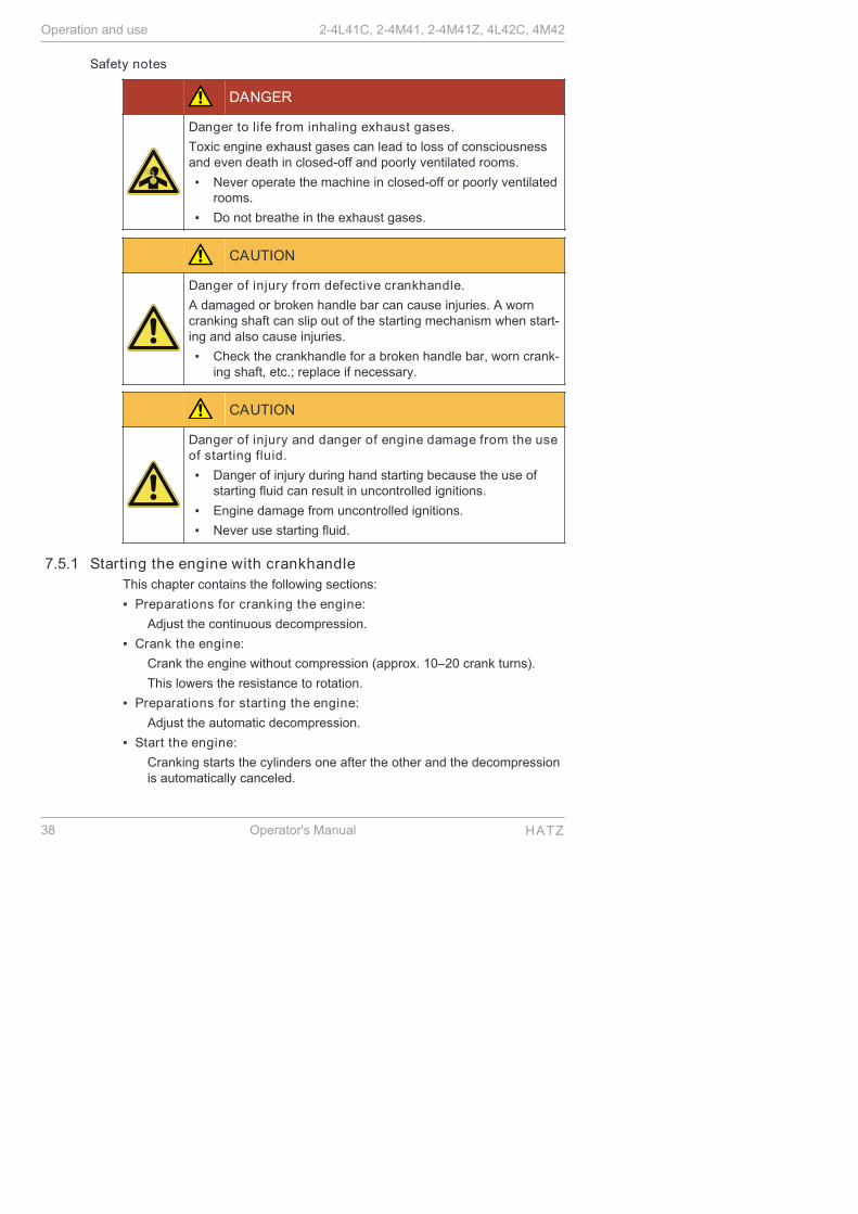
7.5.1 Starting the engine with crankhandleThis chapter contains the following sections:
▪ Preparations for cranking the engine:
Adjust the continuous decompression.
▪ Crank the engine:
Crank the engine without compression (approx. 10–20 crank turns).
This lowers the resistance to rotation.
▪ Preparations for starting the engine:
Adjust the automatic decompression.
▪ Start the engine:
Cranking starts the cylinders one after the other and the decompressionis automatically canceled.
Operation and use 2-4L41C, 2-4M41, 2-4M41Z, 4L42C, 4M42
38 Operator's Manual HATZ

Turning over the engine:
Safety note
CAUTION
Danger of engine damage from decompression while theengine is running.
▪ Do not operate the decompression lever while the engine isrunning.
Overview
Decompression lever
0
Attach the crankhandle Position of operator
Pos. Designation
0 - 3 Positions of the decompression lever
4 Guide sleeve
2-4L41C, 2-4M41, 2-4M41Z, 4L42C, 4M42 Operation and use
HATZ Operator's Manual 39
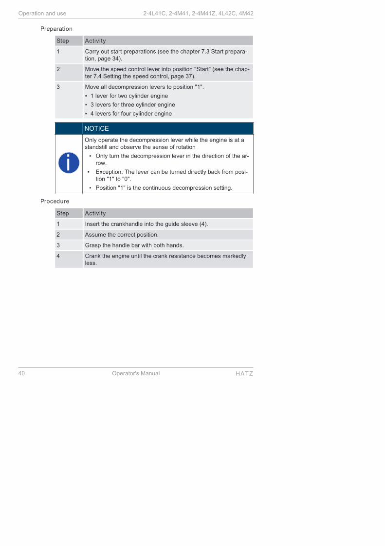
Preparation
Step Activity
1 Carry out start preparations (see the chapter 7.3 Start prepara-tion, page 34).
2 Move the speed control lever into position "Start" (see the chap-ter 7.4 Setting the speed control, page 37).
3 Move all decompression levers to position "1".
▪ 1 lever for two cylinder engine
▪ 3 levers for three cylinder engine
▪ 4 levers for four cylinder engine
NOTICE
iOnly operate the decompression lever while the engine is at astandstill and observe the sense of rotation
▪ Only turn the decompression lever in the direction of the ar-row.
▪ Exception: The lever can be turned directly back from posi-tion "1" to "0".
▪ Position "1" is the continuous decompression setting.
Procedure
Step Activity
1 Insert the crankhandle into the guide sleeve (4).
2 Assume the correct position.
3 Grasp the handle bar with both hands.
4 Crank the engine until the crank resistance becomes markedlyless.
Operation and use 2-4L41C, 2-4M41, 2-4M41Z, 4L42C, 4M42
40 Operator's Manual HATZ

Starting the engine
Safety note
CAUTION
Danger of injury from recoiling of the engine.
▪ Use a crankhandle with a recoil damper.
▪ Hold the handle bar so that it cannot twist and quickly turnthe crank so that continuous traction between the engineand crank is ensured.
▪ If recoil occurs due to cautious turning where the enginestarts in the opposite sense of rotation under certain circum-stances (smoke from the air filter), release the crankhandleimmediately and stop the engine.
▪ To repeat the starting process, wait until the engine hasstopped; only then recommence start preparations.
CAUTION
Danger of injury if the crankhandle recoils or turns with theengine.
▪ The use of crankhandles without recoil damping is not per-missible within the European Union.
Overview
Numbering of the valves and cylinders from the fan side
1 2 3 4
1 2 3 4 5 6 7 8
2-4L41C, 2-4M41, 2-4M41Z, 4L42C, 4M42 Operation and use
HATZ Operator's Manual 41

Crankhandle Attach the crankhandle
Pos. Designation
1 Handle bar
2 Crank arm
3 Drive dog
4 Guide sleeve
Preparation
The decompression lever must be set depending on the number of cylindersof the engines 2-4M41..
0
Operation and use 2-4L41C, 2-4M41, 2-4M41Z, 4L42C, 4M42
42 Operator's Manual HATZ
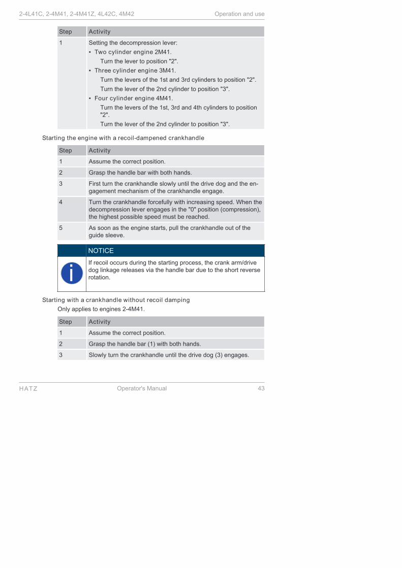
Step Activity
1 Setting the decompression lever:
▪ Two cylinder engine 2M41.
Turn the lever to position "2".
▪ Three cylinder engine 3M41.
Turn the levers of the 1st and 3rd cylinders to position "2".
Turn the lever of the 2nd cylinder to position "3".
▪ Four cylinder engine 4M41.
Turn the levers of the 1st, 3rd and 4th cylinders to position"2".
Turn the lever of the 2nd cylinder to position "3".
Starting the engine with a recoil-dampened crankhandle
Step Activity
1 Assume the correct position.
2 Grasp the handle bar with both hands.
3 First turn the crankhandle slowly until the drive dog and the en-gagement mechanism of the crankhandle engage.
4 Turn the crankhandle forcefully with increasing speed. When thedecompression lever engages in the "0" position (compression),the highest possible speed must be reached.
5 As soon as the engine starts, pull the crankhandle out of theguide sleeve.
NOTICE
iIf recoil occurs during the starting process, the crank arm/drivedog linkage releases via the handle bar due to the short reverserotation.
Starting with a crankhandle without recoil damping
Only applies to engines 2-4M41.
Step Activity
1 Assume the correct position.
2 Grasp the handle bar (1) with both hands.
3 Slowly turn the crankhandle until the drive dog (3) engages.
2-4L41C, 2-4M41, 2-4M41Z, 4L42C, 4M42 Operation and use
HATZ Operator's Manual 43
Step Activity
4 Turn the crankhandle forcefully with increasing speed. When thedecompression lever engages in the "0" position (compression),the highest possible speed must be reached.
5 As soon as the engine starts, pull the crankhandle out of theguide sleeve (4).
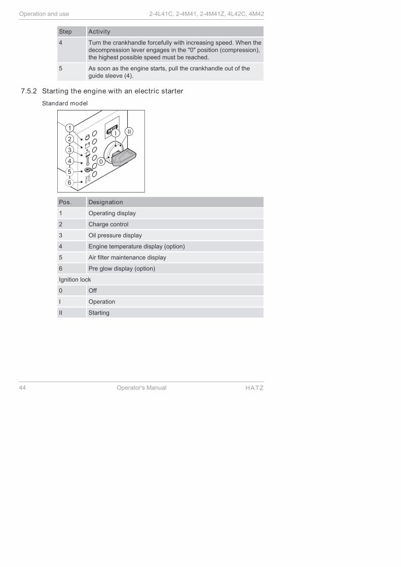
7.5.2 Starting the engine with an electric starter
Standard model
Pos. Designation
1 Operating display
2 Charge control
3 Oil pressure display
4 Engine temperature display (option)
5 Air filter maintenance display
6 Pre glow display (option)
Ignition lock
0 Off
I Operation
II Starting
Operation and use 2-4L41C, 2-4M41, 2-4M41Z, 4L42C, 4M42
44 Operator's Manual HATZ

Procedure
NOTICE
i
▪ Start for max. 30 seconds. If the engine is still not runningafter that, turn the starting key back to position "0" and elimi-nate the cause (see the chapter 9.1 Troubleshooting,page 93).
▪ Turn the starting key to position "0" every time you want tostart the engine.
▪ The anti repeat device in the ignition lock makes it impossi-ble for the starter to engage while the engine is running andbecome damaged.
NOTICE
i
The starter protection module prevents the starter from engag-ing while the engine is running and becoming damaged.
▪ The starter protection module is required when the usercannot detect at the ignition lock if the engine is still runningor is already at a standstill.
▪ In models equipped with a starter protection module, thestarting key must be kept in the 0 position for at least 8 sec-onds before another start is possible after the engine isswitched off.
Step Activity
1 Check the speed control (see the chapter 7.4 Setting the speedcontrol, page 37).
2 Insert the starting key all the way and turn to position "I".
Depending on the model, the following indicators light up:
▪ Charge control (2)
▪ Oil pressure display (3)
▪ Pre glow display (6) at temperatures below 0°C
NOTES:
▪ If the optional engine temperature display (4) lights up, thecylinder head temperature is impermissibly high. Do not startthe engine; eliminate the cause.
▪ The air filter maintenance indicator (5) only lights up duringoperation if the air filter needs to be cleaned or changed.
▪ When the optional pre glow display (6) goes out, continue withstep 3.
3 Turn the starting key to position "II".
2-4L41C, 2-4M41, 2-4M41Z, 4L42C, 4M42 Operation and use
HATZ Operator's Manual 45

Step Activity
4 As soon as the engine is running, release the starting key.
▪ The starting key springs back to position "I" and remains inthis position during operation.
▪ The charge control (2) and oil pressure display (3) go out.
▪ The operating display (1) lights up.
NOTICE
i▪ In case of irregularities, switch off the engine immediately.
▪ Identify the fault and eliminate it.
▪ For details of troubleshooting, see the chapter 9.1 Trouble-shooting, page 93.
Model with exhaust gas return valve
The engines 4L42C and 4M42 are equipped with an exhaust gas returnvalve (EGR). The indicators change as follows:
Pos. Designation
5 Indicator EGR
Blink codes
The indicator (5) only flashes during operation if a problem arises in connec-tion with the exhaust gas return system. This includes a dirty air filter. Thiscan be identified by the following flash code of the indicator (5):
▪ 7 times short flash (approx. 0.5 seconds) and 1 long flash (approx. 1.5seconds).
▪ The flash code indicates that the air filter must be cleaned or changed(see the chapter 8.2.11 Checking and cleaning the air filter cartridge,page 76).
▪ If a different flash code appears, please contact the nearest Hatz service.
Operation and use 2-4L41C, 2-4M41, 2-4M41Z, 4L42C, 4M42
46 Operator's Manual HATZ
NOTICE
iIf the electronics indicate a problem continuously for more than15 minutes without interruption (flash code - display lamp (5)),the engine switches off automatically.
▪ If the problem persists, the engine can be started but onlyfor another 15 minutes.
▪ If necessary, contact your nearest HATZ service station.
Electrical automatic shutoff (additional equipment)
The identifying feature of the electrical automatic shutoff is brief flashing ofall indicators after the starting key is turned to position "I".
NOTICE
i
▪ If the engine stops again immediately after starting, or stopsindependently during operation, this is an indication that amonitoring element of the automatic shutoff has been acti-vated.
▪ Remedy the fault before further starting attempts (see thechapter 9.1 Troubleshooting, page 93).
▪ Despite the automatic shutoff, check the oil level every 8-15operating hours (see the chapter 7.9 Checking the oil leveland adding oil if necessary, page 53).
▪ If the engine switches off due to an electrical fault signal ordue to insufficient oil pressure with the aid of the automaticswitch-off, an emergency start can be attempted by theuser. The user must bear responsibility for any resultingdamage (see the chapter 9.2 Emergency start, page 99).
7.6 Switching off the engine
Methods of switching off the engine
CAUTION
Danger of injury from unauthorized access.
There is a danger of injury if unauthorized persons handle themachine.
▪ Protect the crankhandle and starting key against unauthor-ized access upon breaks in operation or after completingwork.
2-4L41C, 2-4M41, 2-4M41Z, 4L42C, 4M42 Operation and use
HATZ Operator's Manual 47

CAUTION
Danger of engine damage.
▪ Never stop the engine on the decompression lever.
The engine can be switched off in different ways depending on how it isequipped:
▪ Speed control lever (mechanical)
▪ Starting key (electrical)
7.6.1 Switching off the engine (mechanical)
Overview
Procedure
Step Activity
1 Move the speed controller lever to the "STOP" position.
The engine switches off.
2 Additional step for engines with a starter:
▪ Turn the starting key to position "0".
All indicator lamps go out.
NOTICE
iEngines with an automatic switch-off can also be switched off byturning the starting key back to position "0".
Operation and use 2-4L41C, 2-4M41, 2-4M41Z, 4L42C, 4M42
48 Operator's Manual HATZ

7.6.2 Switching off the engine (electrical)
Overview
Pos. Designation
0 Off
I Operation
Procedure
NOTICE
iDanger of full battery discharge.
▪ When the machine is switched off, always turn the startingkey to position "0" or else the battery may become fully dis-charged.
Step Activity
1 Turn the starting key to position "0".
The engine switches off.
All indicator lamps go out.
2 Remove the starting key.
Automatic electrical switch-off with fault storage
This is identified by brief flashing of all indicators after the starting key isturned to position "I".
2-4L41C, 2-4M41, 2-4M41Z, 4L42C, 4M42 Operation and use
HATZ Operator's Manual 49

NOTICE
iIf the engine stops again immediately after starting, or stops in-dependently during operation, this is an indication that a moni-toring element of the automatic shutoff has been activated.
Procedure
Step Activity
1 Check the indicators (2-4).
After the engine comes to a standstill, the fault will continue tobe displayed by the indicator for approx. another 2 minutes.
2 Then the electrical equipment switches off automatically.
3 Set the starting key to position "0".
4 Turn the starting key back to position "I".
The fault display lights up again.
Remedy the fault before making further starting attempts (seethe chapter 9.1 Troubleshooting, page 93).
The indicator goes out at the next start.
7.7 RefuelingThis diesel engine is intended for installation in a machine or for assemblywith other machines to form a machine and does not have its own fuel tank.Follow the instructions from the manufacturer and comply with the followingsafety information.
Safety notes
DANGER
Fire hazard from fuel.
Leaked or spilled fuel can ignite on hot engine parts and causeserious burn injuries.
▪ Only refuel when the engine is switched off.
▪ Never refuel in the vicinity of open flames or sparks that cancause ignition.
▪ Do not smoke.
▪ Do not spill fuel.
Operation and use 2-4L41C, 2-4M41, 2-4M41Z, 4L42C, 4M42
50 Operator's Manual HATZ

CAUTION
Danger of environmental damage from spilled fuel.
Do not overfill the fuel tank and do not spill fuel.
▪ Collect emerging fuel and dispose of it in an environmentallycompatible manner.
CAUTION
Engine damage from using low quality fuel.
The use of fuel that does not meet the specifications can lead toengine damage.
▪ Only use the fuel specified in the chapter 4.2 Fuel, page 23.
▪ The use of fuel that does not meet specifications requiresapproval by Motorenfabrik HATZ (main plant).
7.8 Checking the water separatorOnly for engines 4L42C and 4M42
Safety notes
CAUTION
Danger of environmental damage from spilled fuel.
When water is drained from the water separator, a small amountof fuel is drained as well.
▪ Catch the emerging water-fuel mixture and dispose of it inan environmentally compatible manner.
NOTICE
iThe interval for checking the water separator depends entirelyon the proportion of water in the fuel and on the care exercisedduring refueling; the water separator should be checked at leastonce a week.
Overview
Water in the fuel collects at the lowest point of the fuel filter in the water sep-arator.
2-4L41C, 2-4M41, 2-4M41Z, 4L42C, 4M42 Operation and use
HATZ Operator's Manual 51
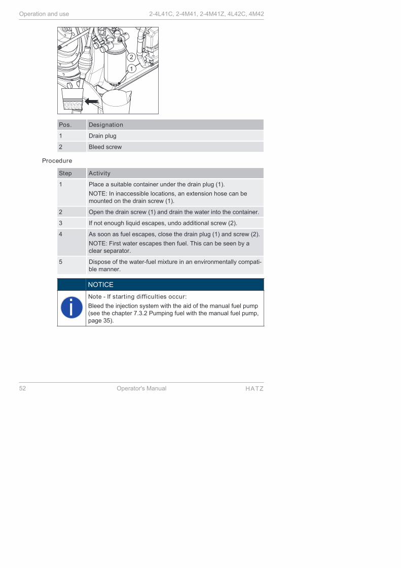
Pos. Designation
1 Drain plug
2 Bleed screw
Procedure
Step Activity
1 Place a suitable container under the drain plug (1).
NOTE: In inaccessible locations, an extension hose can bemounted on the drain screw (1).
2 Open the drain screw (1) and drain the water into the container.
3 If not enough liquid escapes, undo additional screw (2).
4 As soon as fuel escapes, close the drain plug (1) and screw (2).
NOTE: First water escapes then fuel. This can be seen by aclear separator.
5 Dispose of the water-fuel mixture in an environmentally compati-ble manner.
NOTICE
iNote - If starting difficulties occur:
Bleed the injection system with the aid of the manual fuel pump(see the chapter 7.3.2 Pumping fuel with the manual fuel pump,page 35).
Operation and use 2-4L41C, 2-4M41, 2-4M41Z, 4L42C, 4M42
52 Operator's Manual HATZ

7.9 Checking the oil level and adding oil if necessary
Safety notes
CAUTION
Danger of burns.
There is a danger of burns when working on a hot engine.
▪ Wear safety gloves.
CAUTION
Danger of later engine damage.
▪ Operating the engine with an oil level below the min. markor above the max. mark can lead to engine damage.
▪ When checking the oil level, the machine must be horizontaland the engine must have been switched off for a few mi-nutes.
Overview — Checking oil level/adding oil
Pos. Designation
1 Dipstick
2 Code letter on the dipstick
2-4L41C, 2-4M41, 2-4M41Z, 4L42C, 4M42 Operation and use
HATZ Operator's Manual 53

Procedure — Checking oil level/adding oil
Step Activity
1 Switch off the engine and wait several minutes for the engine oilto collect in the crank housing. The machine must be horizontal.
2 Remove contamination on the engine in the area of the dipstick(1).
3 Pull out the dipstick and clean it.
4 Reinsert the dipstick.
5 Pull out the dipstick and check the oil level.
6 If the oil level is close to the min. mark, add engine oil to themax. mark.For specifications and viscosity see chapter 4.3 Engine oil,page 24.
7 Reinsert the dipstick.
Operation and use 2-4L41C, 2-4M41, 2-4M41Z, 4L42C, 4M42
54 Operator's Manual HATZ

8 Maintenance
8.1 General maintenance instructions
Safety notes
WARNING
Danger of injury from the failure to follow the operating in-structions and from performing unauthorized tasks on themachine.
▪ Follow all instructions.
▪ Do not perform activities for which no qualification is availa-ble. Contact properly trained personnel if necessary.
NOTICE
Comply with the safety chapter!
Follow the basic safety instructions in the chapter 3 Safety,page 7.
▪ Maintenance tasks may only be performed by trained personnel.
▪ Accident prevention measures must be in accordance with the local acci-dent prevention regulations.
▪ Perform setting and maintenance work at the specified intervals.
▪ Replace faulty machine parts as soon as possible.
▪ Always use personal protective equipment.
▪ Only use fully functional tools.
▪ Problems may occur if unsuitable spare parts are installed. We cannot ac-cept responsibility for damage and secondary damage that result fromthis. We therefore recommend the use of Hatz original spare parts.
▪ Closely adhere to the maintenance conditions prescribed in this Operator'sManual.
▪ Only make changes on the machine in agreement with the manufacturer.
▪ Only perform maintenance when the engine is switched off.
▪ Adhere to legal regulations when handling and disposing of used oil, fil-ters, coolants, and cleaning agents.
▪ Protect the starting key against unauthorized access.
▪ Disconnect the negative battery terminal before carrying out maintenancework.
▪ After completing maintenance work, check that all tools, bolts, aids andother objects are removed from the machine and that all safety equipmenthas been replaced.
2-4L41C, 2-4M41, 2-4M41Z, 4L42C, 4M42 Maintenance
HATZ Operator's Manual 55

▪ Before starting, ensure that no persons are located in the danger zone ofthe engine or machine.
Performance of maintenance work
The entire machine is designed to be maintenance friendly. Parts that re-quire maintenance are easily accessible.
▪ Perform maintenance work faithfully at the specified intervals to preventpremature wear of the machine.
▪ Follow the notice and warning labels on the machine.
▪ Always retighten screw connections loosened during maintenance work.
▪ After the necessary maintenance and repair work is completed, perform afunction test (test run).
▪ For maintenance work that is not listed and described in the maintenancedocumentation, please contact your nearest HATZ service station.
8.2 Maintenance work
Safety note
CAUTION
Danger of injury if the maintenance instructions are not fol-lowed.
▪ Only perform maintenance while the engine is switched off.
▪ Protect the starting key against unauthorized access.
▪ For engines with a starter: disconnect the negative batteryterminal.
▪ After the maintenance work is completed, ensure that alltools have been removed from the machine.
8.2.1 Maintenance notice label
NOTICE
iDepending on the engine type, one of the maintenance plansshown below is supplied with the engine.
▪ It should be mounted on the engine or machine in a clearlyvisible location.
▪ The maintenance intervals specified on the maintenanceplan must be adhered to (see the chapter 8.2.2 Mainte-nance plan, page 58).
Maintenance 2-4L41C, 2-4M41, 2-4M41Z, 4L42C, 4M42
56 Operator's Manual HATZ

2M41. Without oil sump
2M312M402M41
500h250h
= 1h
maxOIL
0,1 mm0.004"
max
2M41. With oil sump; 3-4M41. and 4M42 in general
.M31/.M40
.M41/.M42
500h250h
= 1h
maxOIL
0,1 mm0.004"
max
2-4L41C, 2-4M41, 2-4M41Z, 4L42C, 4M42 Maintenance
HATZ Operator's Manual 57

2-4L41C; 4L42C
maxOIL
8.2.2 Maintenance planThe degree of contamination of the fuel, the care with which refueling is per-formed and the soiling on the inside of the fuel tank are decisive in determin-ing the change interval of the fuel prefilter and the fuel filter.
Symbol Maintenance in-terval
Maintenance activity/check Chapter
Every 8–15 oper-ating hours or ev-ery day beforestarting
Check the oil level. 7.9 Checking theoil level and add-ing oil if necessa-ry, page 53
Check the intake area of thecombustion air.
8.2.3 Checkingthe intake area ofthe combustionair, page 60
Check the cooling air area. 8.2.4 Checkingthe cooling airarea, page 63
Visual check of the conditionof the crankhandle (handlebar, crank arm, drive dog)
If necessary, lightly greasegliding area between crank-handle and guide sleeve.
−
Maintenance 2-4L41C, 2-4M41, 2-4M41Z, 4L42C, 4M42
58 Operator's Manual HATZ

Symbol Maintenance in-terval
Maintenance activity/check Chapter
250hEvery 250 operat-ing hours
Change the engine oil (2M41.without oil sump, 2-4L41Cand 4L42C in general).
8.2.5 Change theengine oil,page 64
Clean the cooling fan, coolingfins and oil cooler.
8.2.6 Cleaningthe cooling fan,cooling fins andoil cooler,page 66
Check the screw connections. 8.2.7 Checkingthe screw con-nections,page 70
Clean the screen insert in theexhaust pipe.
8.2.8 Cleaningthe screen insertin the exhaustpipe (additionalequipment),page 70
Checking the water separator. 7.8 Checking thewater separator,page 51
Check the fuel prefilter forcontamination and change it ifnecessary.
8.2.9 Changingthe fuel prefilter,page 72
Check the air filter mainte-nance indicator.
8.2.15 Checkingthat the air filtermaintenance indi-cator is workingproperly,page 87
500h
Every 500 operat-ing hours
Change the fuel prefilter. 8.2.9 Changingthe fuel prefilter,page 72
Maintain the dry air filter.
Change the filter cartridge.
8.2.10 Maintain-ing the dry air fil-ter, page 74
Check and set the tappetclearance.
8.2.12 Check andset the tappetclearance,page 78
2-4L41C, 2-4M41, 2-4M41Z, 4L42C, 4M42 Maintenance
HATZ Operator's Manual 59

Symbol Maintenance in-terval
Maintenance activity/check Chapter
Change the engine oil (2M41.with oil sump, 3-4M41. and4M42 in general).
8.2.5 Change theengine oil,page 64
Changing the oil filter. 8.2.13 Changingthe oil filter,page 82
Every 1000 oper-ating hours
Change the fuel filter. 8.2.14 Changethe fuel filter,page 83
In new and generally overhauled engines, after 25 operating hours:
▪ Change the engine oil
▪ Check the tappet clearance and adjust if necessary
▪ Check the screw connections (do not retighten the screws for attachingthe cylinder head)
In case of a low number of operating hours, change the engine oil no laterthan every 12 months, regardless of the actual number of operating hours.
8.2.3 Checking the intake area of the combustion air
Safety notes
CAUTION
Danger of burns.
There is a danger of burns when working on a hot engine.
▪ Let the engine cool.
▪ Wear safety gloves.
NOTICE
iIn case of heavy contamination, shorten the maintenance inter-vals accordingly (see the chapter 8.2.2 Maintenance plan,page 58).
Maintenance 2-4L41C, 2-4M41, 2-4M41Z, 4L42C, 4M42
60 Operator's Manual HATZ
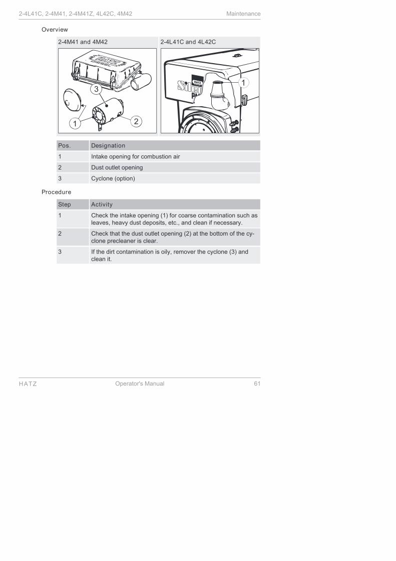
Overview
2-4M41 and 4M42
3
2-4L41C and 4L42C
Pos. Designation
1 Intake opening for combustion air
2 Dust outlet opening
3 Cyclone (option)
Procedure
Step Activity
1 Check the intake opening (1) for coarse contamination such asleaves, heavy dust deposits, etc., and clean if necessary.
2 Check that the dust outlet opening (2) at the bottom of the cy-clone precleaner is clear.
3 If the dirt contamination is oily, remover the cyclone (3) andclean it.
2-4L41C, 2-4M41, 2-4M41Z, 4L42C, 4M42 Maintenance
HATZ Operator's Manual 61

Electrical air filter maintenance display
2-4L41C and 2-4M41 4L42C and 4M42
Pos. Designation
5 Air filter maintenance display
Mechanical air filter maintenance display
Pos. Designation
1 Red field
Procedure
Step Activity
For the electrical air filter maintenance display:
Maintenance 2-4L41C, 2-4M41, 2-4M41Z, 4L42C, 4M42
62 Operator's Manual HATZ

Step Activity
1 Briefly let the engine run at maximum speed and watch for theindicator (5) to light up for a short period – depending on theversion.
In the engines 4L42C and 4M42, the following flash code indi-cates that maintenance work is required on the air filter
▪ 7 short flashes (approx. 0.5 seconds) and
▪ 1 long flash (approx. 1.5 seconds)
(see the chapter 8.2.10 Maintaining the dry air filter,page 74).
With mechanical air filter maintenance display:
1 Briefly let the engine run at maximum speed and watch for thevisible red field (1) in the mechanical air filter maintenance dis-play.
The visible red field (1) indicates that maintenance work is re-quired on the air filter (see the chapter 8.2.10 Maintaining thedry air filter, page 74).
8.2.4 Checking the cooling air area
Safety notes
CAUTION
Danger of burns.
There is a danger of burns when working on a hot engine.
▪ Let the engine cool before maintenance.
CAUTION
Danger of injury.
When working with compressed air, foreign bodies may fly intoyour eyes.
▪ Wear safety goggles.
▪ Never direct the compressed air jet toward people or towardyourself.
2-4L41C, 2-4M41, 2-4M41Z, 4L42C, 4M42 Maintenance
HATZ Operator's Manual 63

CAUTION
Danger of engine damage from overheating.
The engine temperature display (option) lights up as soon as theengine becomes impermissibly hot.
▪ Switch off the engine immediately and eliminate the cause.
NOTICE
iIn case of heavy contamination, shorten the maintenance inter-vals accordingly (see the chapter 8.2.2 Maintenance plan,page 58).
Procedure
Step Activity
1 Check the supply and exhaust air areas for coarse contamina-tion such as leaves, heavy dust deposits, etc., and clean ifnecessary (see the chapter 8.2.6 Cleaning the cooling fan,cooling fins and oil cooler, page 66).
8.2.5 Change the engine oil
Safety notes
CAUTION
Danger of burns.
When working on the engine there is a danger of burns from hotoil.
▪ Wear personal protective equipment (gloves).
▪ Collect the used oil and dispose of it according to local envi-ronmental regulations.
NOTICE
i▪ The engine must be level.
▪ The engine must be switched off.
▪ Only drain engine oil while it is warm.
▪ The engine oil should be changed when the oil filter ischanged.
Maintenance 2-4L41C, 2-4M41, 2-4M41Z, 4L42C, 4M42
64 Operator's Manual HATZ

Overview
M41 L41
Pos. Designation
1 Oil drain screw
2 Drain pipe
Draining the oil
Step Activity
1 Unscrew the oil drain screw (1) and drain the oil entirely.
When unscrewing the oil drain screw (1) on engines of type2-4L41C and 4L42C, ensure that the drain pipe (2) is not loos-ened. Hold it with an open-end wrench.
2 Screw in the cleaned oil drain screw (1) with the new gasketand tighten.
Overview
2-4L41C, 2-4M41, 2-4M41Z, 4L42C, 4M42 Maintenance
HATZ Operator's Manual 65

Pos. Designation
1 Dipstick
2 Mark on the dipstick
Adding oil
Step Activity
1 Add engine oil to the max. mark on the dipstick (1).
▪ For the specification and viscosity, see the chapter 4.3 En-gine oil, page 24.
▪ The mark of the dipstick (2) indicates whether the engine isequipped with an oil sump or not (see the chapter 4.1 En-gine, page 22).
2 Reinsert the dipstick (1).
3 Check the oil level after a short test run and correct if necessa-ry.
8.2.6 Cleaning the cooling fan, cooling fins and oil cooler
Safety notes
DANGER
Danger of explosion from flammable cleaning agents.
Cleaning with benzene is an explosion hazard. It is highly flam-mable, can become electrostatically charged and can generatean explosive gas-air mixture.
▪ Use halogen-free, cold cleaners with a high flashpoint forcleaning.
CAUTION
Danger of burns.
There is a danger of burns when working on a hot engine.
▪ Let the engine cool before maintenance.
Maintenance 2-4L41C, 2-4M41, 2-4M41Z, 4L42C, 4M42
66 Operator's Manual HATZ

CAUTION
Danger of injury.
When working with compressed air, foreign bodies may fly intoyour eyes.
▪ Wear safety goggles.
▪ Never direct the compressed air jet toward people or towardyourself.
CAUTION
Danger of engine damage from overheating.
The engine temperature display (option) lights up as soon as theengine becomes impermissibly hot.
▪ Switch off the engine immediately and eliminate the cause.
CAUTION
Danger of damage to the machine from incorrect enginecleaning.
▪ Do not spray components of the electrical equipment with awater jet or high pressure jet during cleaning.
▪ Do not use gasoline or acid-based cleaning agents.
CAUTION
Damage from inadequate engine cooling.
Only operate the engine when all covers are installed.
NOTICE
iIn case of heavy contamination, shorten the maintenance inter-vals accordingly (see the chapter 8.2.2 Maintenance plan,page 58).
2-4L41C, 2-4M41, 2-4M41Z, 4L42C, 4M42 Maintenance
HATZ Operator's Manual 67

Overview — Preparatory activities
Pos. Designation
1 Baffle plate
Preparation
Step Activity
1 Unscrew the following on encapsulated engines:
▪ Hood
▪ Side wall with speed control lever
▪ Cover plate on operating side
▪ Exhaust air duct
▪ Cover plate on exhaust side
(see the chapter 5 Engine design, page 25).
1 Remove the following on engines without a capsule:
▪ Side trim panel
▪ Cooling air guide for lubrication oil cooler
2 Unscrew the baffle plate (1)
Maintenance 2-4L41C, 2-4M41, 2-4M41Z, 4L42C, 4M42
68 Operator's Manual HATZ

Overview — Cleaning
Procedure — Cleaning
Step Activity
Cleaning in case of dry dirt contamination
1 Clean the cooling fan, cylinder head and cylinder with a suita-ble brush.
2 Blow out the entire cooling air area with compressed air.
3 Blow out the oil cooler with compressed air only.
NOTE:
▪ Do not place the compressed air gun against the sensitiveradiator fins.
4 On encapsulated engines, also clean the area between thefloor plate and crankcase.
5 Mount the capsule and air guide parts again.
Cleaning of wet or oily dirt contamination
1 Disconnect the negative terminal of the battery.
2 Manually clean the alternator and regulator.
3 Cover the alternator with the installed regulator and do notspray directly.
4 Spray the entire area with a suitable cleaning solution accord-ing to manufacturer instructions and then clean off with a jet ofwater.
Do not spray components of the electrical equipment with awater jet or high pressure jet during cleaning.
5 Blow dry the engine with compressed air.
2-4L41C, 2-4M41, 2-4M41Z, 4L42C, 4M42 Maintenance
HATZ Operator's Manual 69

Step Activity
6 Determine the cause of the oil contamination and have leakscorrected by the HATZ service station.
7 Mount the capsule and air guide parts again.
8 Let the engine run warm to prevent rust formation.
8.2.7 Checking the screw connections
NOTICE
i▪ Do not retighten the screws for attaching the cylinder head.
▪ The adjustment screws on the speed regulator and the in-jection system are secured with locking varnish and are notpermitted to be tightened or adjusted.
▪ Only retighten loose screw connections. Screw connectionscan be secured with thread locking adhesive or tightened toa defined torque. Retightening tight screw connections cancause damage.
Procedure
Step Activity
1 Check the condition of all screw connections and ensure thatthey are tight (for exceptions, see note).
2 Tighten any lose screw connections.
8.2.8 Cleaning the screen insert in the exhaust pipe (additionalequipment)
Safety notes
CAUTION
Danger of burns.
There is a danger of burns when working on a hot engine.
▪ Let the engine cool before maintenance.
Maintenance 2-4L41C, 2-4M41, 2-4M41Z, 4L42C, 4M42
70 Operator's Manual HATZ

CAUTION
Danger of injury
There is a danger of injury when performing cleaning work at theexhaust screen.
▪ Wear safety gloves.
NOTICE
iOperation of the engine for a lengthy period without a load orwith only a small load can result in premature deposits on thescreen insert.
Shorten the maintenance interval accordingly.
Overview
Pos. Designation
1 Pipe clamp
2 Screen insert
Procedure
Step Activity
1 Release the pipe clamp (1) and remove it with the exhaustpipe.
2 Remove deposits on the screen insert (2).
3 Check the screen insert for cracks or breakage, and replace ifnecessary.
2-4L41C, 2-4M41, 2-4M41Z, 4L42C, 4M42 Maintenance
HATZ Operator's Manual 71

8.2.9 Changing the fuel prefilter
Safety notes
DANGER
Fire hazard from fuel.
Leaked or spilled fuel can ignite on hot engine parts and causeserious burn injuries.
▪ Never refuel in the vicinity of open flames or sparks that cancause ignition.
▪ Do not smoke.
▪ Do not spill fuel.
CAUTION
Danger of injury
Repeated contact with diesel fuel can cause chapped andcracked skin.
▪ Wear safety gloves.
CAUTION
Danger of environmental damage from spilled fuel.
When the filter is removed, a small amount of fuel is drained aswell.
▪ Collect emerging fuel and dispose of it in an environmentallycompatible manner.
CAUTION
Dirt particles can damage the injection system.
▪ Maintain clean conditions to ensure that dirt does not enterthe fuel line.
Maintenance 2-4L41C, 2-4M41, 2-4M41Z, 4L42C, 4M42
72 Operator's Manual HATZ

Overview
Pos. Designation
1 Fuel lines
2 Fuel prefilter
Procedure
Step Activity
1 Place a suitable container under the filter to collect emergingfuel.
2 Close the fuel feed line.
3 Pull the fuel lines (1) off of the fuel prefilter (2) on both sides.
4 Dispose of the old filter in accordance with local environmentalregulations.
5 Insert a new fuel prefilter.
Note the following:
▪ Arrow for flow direction
▪ Position of the fuel tank: HIGH or LOW
▪ Installation position/flow-through direction should be as verti-cal as possible
6 Open the fuel feed line.
2-4L41C and 2-4M41
7 To simplify the starting procedure, it is recommended that youpre-pump the fuel using the manual lever at the fuel feed pumpuntil you hear fuel flow back through the return line into the fueltank (see the chapter 7.3.1 Pumping fuel with the manual lev-er, page 34).
8 Perform a leak tightness test by activating the manual lever.
2-4L41C, 2-4M41, 2-4M41Z, 4L42C, 4M42 Maintenance
HATZ Operator's Manual 73

Step Activity
9 After completion, insert the access cover to the fuel feed pumpback in the side wall.
4L42C and 4M42
7 If you have difficulties starting the engine, bleed the injectionsystem with the aid of the manual fuel pump (see the chapter7.3.2 Pumping fuel with the manual fuel pump, page 35).
8.2.10 Maintaining the dry air filter
NOTICE
i
▪ Immediately clean the filter cartridge if the maintenance dis-play appears at maximum speed.
▪ The air filter cartridge either needs to be replaced, orcleaned or checked depending on the degree of contamina-tion.
▪ Renew the filter cartridge after a use period of 500 operatinghours.
▪ Four cylinder engines have two filter cartridges.
Overview of engines 2-4 L41C and 4L42C
Pos. Designation
1 Screw
2 Cover
3 Filter cartridge
4 Air filter housing
5 Spacer
6 Bushing
Maintenance 2-4L41C, 2-4M41, 2-4M41Z, 4L42C, 4M42
74 Operator's Manual HATZ

Pos. Designation
7 Clamp
Removing the air filter cartridge - engines 2-4L41C and 4L42C
Step Activity
1 Remove the capsule hood.
2 Remove adherent dirt in the area of the air filter housing (4).
3 Only loosen the screws (1) to the point where you can lift offthe complete air filter housing (4).
4 Cover the opening in the intake pipe to prevent ingress of dirtand other foreign bodies.
5 On three cylinder engines, open the clamp (7).
▪ On three cylinder engines, the cover (2) is additionally heldby a clamp (7).
6 Open the air filter housing (4).
7 Take out the filter cartridge (3).
8 Clean the air filter housing (4) and cover (2).
9 Renew the bushing (6) if the spacer (5) is loose.
▪ The spacer (5) is connected with the screw (1) by the elasticbushing (6) to ensure that it cannot fall into the intake pipeduring disassembly and assembly.
Overview of the engines 2-4M41. and 4M42
Pos. Designation
1 Clamp
2 Air filter housing cover
3 Screw
2-4L41C, 2-4M41, 2-4M41Z, 4L42C, 4M42 Maintenance
HATZ Operator's Manual 75

Pos. Designation
4 Filter cover
5 Spacer
6 Bushing
7 Filter cartridge
8 Air filter housing
Removing the air filter cartridge - engines 2-4M41. and 4M42
Step Activity
1 Release the clamps (1) and remove the cover of the air filterhousing (2).
2 Remove adherent dirt in the air filter area.
3 Only loosen the screws (3) to the point where the filter cover(4) can be removed with the filter cartridge (7).
4 Cover the opening in the intake pipe to prevent ingress of dirtand other foreign bodies.
5 Clean the air filter housing cover (2), filter cover (4) and air fil-ter housing (8).
6 Renew the bushing (6) if the spacer (5) is loose.
▪ The spacer (5) is connected with the screw (3) by the elasticbushing (6) to ensure that it cannot fall into the intake pipeduring disassembly and assembly.
8.2.11 Checking and cleaning the air filter cartridge
Safety notes
CAUTION
Danger of injury.
When working with compressed air, foreign bodies may fly intoyour eyes.
▪ Wear safety goggles.
▪ Never direct the compressed air jet toward people or towardyourself.
Maintenance 2-4L41C, 2-4M41, 2-4M41Z, 4L42C, 4M42
76 Operator's Manual HATZ

NOTICE
i▪ The pressure must not exceed 5 bar.
▪ A distance of approx. 150 mm must be maintained betweenthe filter cartridge and the compressed air gun.
▪ Even minor damage in the areas of the sealing surface, filterpaper or filter cartridge makes it impossible to reuse the fil-ter cartridge.
Overview
Clean the filter cartridge Check the air filter cartridge
Pos. Designation
1 Sealing surface
Procedure
Step Activity
Dry contamination
1 Blow out the filter cartridge with dry compressed air from the in-side to the outside until dust no longer emerges.
2 Check the sealing surfaces (1) of the filter cartridge for damage.
3 Check the filter cartridge for cracks in the filter paper and otherdamage by holding it against the light at a slant or letting lightfrom a lamp shine through it.
4 Replace the filter cartridge if necessary (see note).
Moist or oily contamination
1 Renew the filter cartridge.
2-4L41C, 2-4M41, 2-4M41Z, 4L42C, 4M42 Maintenance
HATZ Operator's Manual 77

Mechanical air filter maintenance display
Pos. Designation
1 Red field
2 Reset button
Mounting the air filter cartridge
Step Activity
1 When assembling, mount the parts individually one after the oth-er to make sure they are correctly seated and to ensure leaktightness.
2 After the filter is mounted, unlock the visible red field (1) in themaintenance display by pressing the reset button (2).
8.2.12 Check and set the tappet clearance
Safety notes
CAUTION
Danger of burns.
There is a danger of burns when working on a hot engine. Onlyperform the settings while the engine is cold (10-30°C).
▪ Let the engine cool.
CAUTION
Damage from inadequate engine cooling.
Only operate the engine when all covers are installed.
Maintenance 2-4L41C, 2-4M41, 2-4M41Z, 4L42C, 4M42
78 Operator's Manual HATZ

Overview — Preparatory activities
Pos. Designation
1 Square opening
2 Hex nut
3 Cylinder head cover
Preparation — Adjusting the tappet clearance
Step Activity
1 On encapsulated engines, remove the hood of the capsule (seethe chapter 5 Engine design, page 25).
2 Remove the hex nut (2) and remove the cylinder head cover (3).
3 Remove the air guide housing cover (see the chapter 5 Enginedesign, page 25) or the belt guard.
4 Insert the ratchet or T-piece 1/2" with the required extension (1)into the square opening.
NOTICE
iTurn the engine in the sense of rotation.
Anti-clockwise in both cases - flywheel side or timing cover side.
2-4L41C, 2-4M41, 2-4M41Z, 4L42C, 4M42 Maintenance
HATZ Operator's Manual 79

Numbering of the valves and cylinders from the fan side
1 2 3 4
1 2 3 4 5 6 7 8
Setting method for two cylinder engine
Step Activity
1 Set the valve of the 1st cylinder – fan side – to overlap (outletvalve not yet closed, intake valve begins to open).
2 Turn the crankshaft by 180° in the sense of rotation and checkthe valves of the 2nd cylinder.
3 Continue turning the crankshaft by 180° in the sense of rotationand check the valves of the first cylinder.
Setting method for three and four cylinder engines
Type Valve no. ... fullyopened
Check the valves ofthe ... cylinder
3-cylinder1
5
3
3rd cylinder
2nd cylinder
1st cylinder
4th cylinder1
5
7
3
3rd cylinder
4th cylinder
2nd cylinder
1st cylinder
Maintenance 2-4L41C, 2-4M41, 2-4M41Z, 4L42C, 4M42
80 Operator's Manual HATZ

Overview — Adjusting the tappet clearance
Pos. Designation
1 Hex nut
2 Adjusting screw
3 Feeler gauge
Procedure — Adjusting the tappet clearance
Step Activity
1 Check the tappet clearance with the feeler gauge (3). For thesetting, see the chapter 4 Technical data, page 22.
2 If the tappet clearance needs to be corrected:
▪ Release the hex nut (1).
▪ Turn the adjustment screw (2) so the feeler gauge (3) can bepulled through with a barely perceptible resistance after thehex nut (1) is tightened again.
3 Repeat the above procedure for the entire valve area, takingspecial care to use the described adjustment method.
4 Mount the cylinder head cover again:
▪ Always renew the gaskets.
▪ Use the fixing nuts for the cylinder head cover no more thantwice before renewing them.
▪ Tightening torque: 10 Nm.
5 Mount all covers.
NOTE:
▪ Under no circumstances is the engine permitted to be operat-ed if not all covers are mounted.
2-4L41C, 2-4M41, 2-4M41Z, 4L42C, 4M42 Maintenance
HATZ Operator's Manual 81

Step Activity
6 After a brief trial run, check the cylinder head cover for tight-ness.
8.2.13 Changing the oil filter
Safety notes
CAUTION
Danger of burns.
When working on the engine there is a danger of burns from hotoil.
▪ Wear personal protective equipment (gloves).
▪ Collect the used oil and dispose of it according to local envi-ronmental regulations.
Overview
Procedure
Step Activity
1 Release the oil filter with a strap wrench and quickly unscrewand remove it.
▪ HATZ order no. for strap wrench: 620 307 01.
2 Dispose of the old filter in accordance with local environmentalregulations.
3 Wipe spilled engine oil out of the oil baffle.
4 Lightly oil the sealing lip of the new oil filter.
5 Screw in the oil filter and tighten it by hand.
Maintenance 2-4L41C, 2-4M41, 2-4M41Z, 4L42C, 4M42
82 Operator's Manual HATZ

Step Activity
6 Add engine oil to the max. mark on the dipstick.
▪ For the specifications and viscosity, see the chapter 4.3 En-gine oil, page 24.
▪ The mark on the dipstick indicates whether the engine isequipped with an oil sump or not (see the chapter 4.1 En-gine, page 23).
7 Reinsert the dipstick.
8 Check the oil level after a short test run and correct if necessary.
9 Check the oil filter for tightness and retighten by hand if neces-sary.
8.2.14 Change the fuel filter
Safety notes
DANGER
Fire hazard from fuel
Leaked or spilled fuel can ignite on hot engine parts and causeserious burn injuries.
▪ Do not spill fuel.
▪ No open flames when working on the fuel system.
▪ Do not smoke
CAUTION
Danger of injury
Repeated contact with diesel fuel can cause chapped andcracked skin.
▪ Wear safety gloves.
2-4L41C, 2-4M41, 2-4M41Z, 4L42C, 4M42 Maintenance
HATZ Operator's Manual 83

CAUTION
Danger of environmental damage from spilled fuel.
When the filter is removed, a small amount of fuel is drained aswell.
▪ Collect emerging fuel and dispose of it in an environmentallycompatible manner.
CAUTION
Dirt particles can damage the injection system.
▪ Maintain clean conditions to ensure that dirt does not enterthe fuel line.
Overview 2-4L41C and 2-4M41.
Pos. Designation
1 Strap wrench (HATZ order no.: 620 307 01)
Procedure 2-4L41C and 2-4M41
Step Activity
1 On encapsulated engines:
▪ Lift off the capsule hood
(see the chapter 5 Engine design, page 25).
On engines without a capsule:
▪ Remove the side trim panel
(see the chapter 5 Engine design, page 25).
2 Place a suitable container under the filter to collect emergingfuel.
3 Close the fuel feed line.
Maintenance 2-4L41C, 2-4M41, 2-4M41Z, 4L42C, 4M42
84 Operator's Manual HATZ
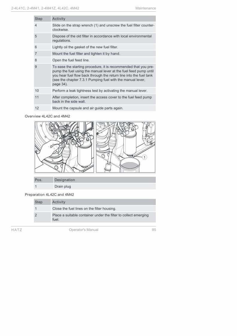
Step Activity
4 Slide on the strap wrench (1) and unscrew the fuel filter counter-clockwise.
5 Dispose of the old filter in accordance with local environmentalregulations.
6 Lightly oil the gasket of the new fuel filter.
7 Mount the fuel filter and tighten it by hand.
8 Open the fuel feed line.
9 To ease the starting procedure, it is recommended that you pre-pump the fuel using the manual lever at the fuel feed pump untilyou hear fuel flow back through the return line into the fuel tank(see the chapter 7.3.1 Pumping fuel with the manual lever,page 34).
10 Perform a leak tightness test by activating the manual lever.
11 After completion, insert the access cover to the fuel feed pumpback in the side wall.
12 Mount the capsule and air guide parts again.
Overview 4L42C and 4M42
Pos. Designation
1 Drain plug
Preparation 4L42C and 4M42
Step Activity
1 Close the fuel lines on the filter housing.
2 Place a suitable container under the filter to collect emergingfuel.
2-4L41C, 2-4M41, 2-4M41Z, 4L42C, 4M42 Maintenance
HATZ Operator's Manual 85

Step Activity
3 Release the drain screw (1) and drain the fuel.
Overview 4L42C and 4M42
Pos. Designation
1 Strap wrench (HATZ order no.: 620 307 01)
2 Gasket
Procedure 4L42 C and 4M42
Step Activity
1 Slide on the strap wrench (1) and unscrew the fuel filter counter-clockwise.
2 Dispose of the old filter in accordance with local environmentalregulations.
3 Lightly oil the gasket (2) of the new fuel filter.
4 Mount the fuel filter and tighten it by hand.
5 Open the fuel feed line.
6 Bleed the injection system with the aid of the manual fuel pump(see the chapter 7.3.2 Pumping fuel with the manual fuel pump,page 35).
7 After a brief trial run, check the fuel filter for leak tightness andretighten by hand.
Maintenance 2-4L41C, 2-4M41, 2-4M41Z, 4L42C, 4M42
86 Operator's Manual HATZ

8.2.15 Checking that the air filter maintenance indicator is workingproperly
Overview
Electrical air filter maintenance display
Mechanical air filter maintenance display
Hose of air intake pipe
Pos. Designation
1 Red field
2 Reset button
3 Hose
5 Air filter maintenance display
Ignition lock
0 Off
I Operation
II Start
2-4L41C, 2-4M41, 2-4M41Z, 4L42C, 4M42 Maintenance
HATZ Operator's Manual 87

Procedure
Step Activity
1 Remove the capsule hood and the side panel trim (see thechapter 5 Engine design, page 25).
2 Turn the starting key to position I.
3 Pull the hose (3) off of the exhaust manifold.
Electrical air filter maintenance display
NOTE:
On engine types 4L42 and 4M42, this function test cannot beperformed.
4 Generate a vacuum by sucking forcefully at the hose end.
The indicator (5) lights up.
5 If there is no reaction, check the following:
▪ Electrical part; cable connections, etc.
▪ Indicator
▪ Function of the maintenance switch.
Mechanical air filter maintenance display
4 Generate a vacuum by sucking forcefully at the hose end.
The red field (1) engages.
5 After the function test, unlock the red field (1) by pressing the re-set button (2).
After the function test
6 Replace the faulty parts.
7 Reattach the hose (3) of the exhaust manifold.
8 Mount the capsule and air guide parts again.
Maintenance 2-4L41C, 2-4M41, 2-4M41Z, 4L42C, 4M42
88 Operator's Manual HATZ

8.2.16 Renewing the poly v belt and checking the function of the switch-off unit
NOTICE
i
When changing the belt:
▪ Always check the function of the switch-off unit. The switch-off pin must emerge by spring force, or else the machine willnot switch off automatically if the belt tears.
▪ If the grooves are broken off or bent, renew the damagedpulley.
▪ To be absolutely sure that you order the right poly v belt – interms of the length – it is recommended that you measurethe diameter of the fan-side pulley and use this as the basisfor your selection.
Belt types
Because of the different diameters of the fan-side pulleys, in combinationwith different engine types and versions, various lengths of poly v belts areused.
Type and engineversion
ID number Belt length mm Fan pulleyØ mm
2L41C 502 031 00 920 72
All remaining typesand versions
501 415 00 910 64
Overview — Removing the poly v belt
Pos. Designation
1 Cylinder screw
2 Tension pulley
2-4L41C, 2-4M41, 2-4M41Z, 4L42C, 4M42 Maintenance
HATZ Operator's Manual 89

Pos. Designation
3 Pulley
Procedure — Removing the poly v belt
Step Activity
1 Unscrew one cylinder screw (1) from the pulley (3).
2 Push back the tension pulley (2) and lock it using the cylinderscrew (1).
3 Unscrew the pulley (3).
4 Check the pulley (3) for broken or bent grooves.
5 Remove the poly v belt.
Overview — Checking the function of the switch-off unit of the belt monitor-ing system
Pos. Designation
1 Tension pulley
2 Angle lever
3 Switch-off pin
Maintenance 2-4L41C, 2-4M41, 2-4M41Z, 4L42C, 4M42
90 Operator's Manual HATZ

Procedure — Checking the function of the switch-off unit of the belt monitor-ing system
Step Activity
1 Release the piston with the tension pulley (1) by removing thecylinder screw.
▪ The piston with the tension pulley is pushed out of the housingby spring pressure.
▪ The angle lever (2) turns downward and releases the switch-off pin (3).
▪ The switch-off pin (3) must emerge by spring force, or else themachine will not switch off automatically if the belt tears.
2 If there is no reaction, please contact the nearest HATZ servicestation.
Overview — Mounting the poly v belt
Pos. Designation
1 Switch-off pin
2 Tension pulley
3 Housing
Procedure — Mounting the poly v belt
Step Activity
1 Slide in the switch-off pin (1).
2 Slide the piston with the tension pulley (2) into the housing (3)and lock it using the cylinder screw.
3 Position the poly v belt centrally on the pulley of the fan wheel,the tension pulley (2) and the pulley at the bottom.
2-4L41C, 2-4M41, 2-4M41Z, 4L42C, 4M42 Maintenance
HATZ Operator's Manual 91

Overview — Centering the pulley
Pos. Designation
1 Cylinder screw
Procedure — Centering the pulley
Step Activity
1 Lightly secure the pulley with a cylinder screw (1) without plac-ing the pulley fully on the centering.
2 Insert a large screwdriver between the hydraulic belt tensionerand pulley and push down until it slides fully into the centering.
3 Insert the remaining cylinder screws (1) and tighten.
Maintenance 2-4L41C, 2-4M41, 2-4M41Z, 4L42C, 4M42
92 Operator's Manual HATZ

9 Faults
9.1 Troubleshooting
Troubleshooting notes
If the cases listed below have been worked through but the fault continues topersist, please contact your nearest HATZ service station.
Type of fault Possible causes Remedy Chapter
The engine doesnot start or doesnot start immedi-ately, but it can beturned with thestarter.
Move the speedcontrol lever to the"STOP" position.
Depending on thepossibility or re-quirement, placethe lever in eitherthe 1/2 start ormax. START posi-tion. The levermust be fixed inthis position.
7.4 Settingthe speedcontrol,page 37
7.5 Startingthe engine,page 37
No fuel at the injec-tion pump.
Refuel. 7.7 Refuel-ing, page 50
Activate the feedpump until the fuelcan be heard toflow back throughthe return line intothe fuel tank.
7.3 Startpreparation,page 34
Systematicallycheck the entirefuel supply:
If this does notyield results:
▪ Check the feedline to the en-gine.
▪ Check the fuelprefilter.
▪ Check the fuel fil-ter.
▪ Check the func-tion of the feedpump.
8.2.9Changingthe fuel pre-filter,page 72
8.2.14Change thefuel filter,page 83
2-4L41C, 2-4M41, 2-4M41Z, 4L42C, 4M42 Faults
HATZ Operator's Manual 93

Type of fault Possible causes Remedy Chapter
After every extended period of disuse, ifyou experience difficulties starting theengine that can be eliminated by activat-ing the feed pump for a lengthy period,check that the fuel system is correctlysized.
6.2 Assem-bly instruc-tions,page 31
Insufficientcompression:
▪ Wrong tappetclearance.
Check the tappetclearance and ad-just if necessary.
8.2.12Check andset the tap-pet clear-ance,page 78▪ Cylinder and/or
piston ring wear.Contact Hatz serv-ice.
▪ Faulty automaticdecompression.
Contact Hatz serv-ice.
Injection nozzle isnot functional.
Contact Hatz serv-ice.
Torn cooling fanbelt.
Renew the poly vbelt.
8.2.16 Re-newing thepoly v beltand check-ing the func-tion of theswitch-offunit,page 89
At low tempera-tures
Pre glow system isfaulty (additionalequipment).
Contact Hatz serv-ice.
Fuel gelled due toinsufficient cold re-sistance.
Check whether thefuel that emergesfrom the detachedfuel feed line di-rectly at the injec-tion pump is clearand not cloudy. Ifthe fuel has gelled,either warm the en-gine or drain theentire fuel supplysystem. Fill with atemperature-resist-ance fuel mixture.
4.2 Fuel,page 23
7.7 Refuel-ing, page 50
8.2.9Changingthe fuel pre-filter,page 72
8.2.14Change thefuel filter,page 83
Faults 2-4L41C, 2-4M41, 2-4M41Z, 4L42C, 4M42
94 Operator's Manual HATZ

Type of fault Possible causes Remedy Chapter
Starter speed is toolow:
▪ Oil is too vis-cous.
Change the engineoil and add oil ofthe right viscosityclass.
4.3 Engineoil, page 24
8.2.5Change theengine oil,page 64
▪ Insufficientlycharged battery.
Check the batteryand contact theservice center ifnecessary.
3.2.4 Elec-trical equip-ment,page 18
Machine is not un-coupled.
If possible, sepa-rate the enginefrom the machineby uncoupling it.
The starter doesnot switch on andthe engine doesnot turn.
Irregularities in theelectrical equip-ment:
▪ Battery and/orother cable con-nections are in-correctly con-nected.
▪ Cable connec-tions are looseand/or oxidized.
▪ Battery is faultyand/or not load-ed.
▪ Faulty starter.
▪ Faulty relay,monitoring ele-ments, etc.
Check the electri-cal equipment andtheir components.
Contact Hatz serv-ice.
3.2.4 Elec-trical equip-ment,page 18
The engine starts,but does not con-tinue running afterthe starter isswitched off.
The speed controllever is not suffi-ciently set to theStart direction.
Set the lever to theStart position.
7.5 Startingthe engine,page 37
Machine is not un-coupled.
If possible, sepa-rate the enginefrom the machineby uncoupling it.
2-4L41C, 2-4M41, 2-4M41Z, 4L42C, 4M42 Faults
HATZ Operator's Manual 95

Type of fault Possible causes Remedy Chapter
Fuel prefilter isclogged.
Change the fuelprefilter.
8.2.9Changingthe fuel pre-filter,page 72
Fuel filter is clog-ged.
Change the fuel fil-ter.
8.2.14Change thefuel filter,page 83
Fuel supply is inter-rupted.
Systematicallycheck the entirefuel supply.
Stop signal frommonitoring ele-ments that are as-sociated with theautomatic switch-off (additionalequipment):
▪ No oil pressure.
▪ Dirty air filterunit.
▪ Faulty threephase alternator.
▪ Check the oil lev-el.
▪ Check the de-gree of dirt con-tamination of theair filter, andclean or renew itif necessary.
▪ Contact Hatzservice.
7.9 Check-ing the oillevel andadding oil ifnecessary,page 53
8.2.10Maintainingthe dry airfilter,page 74
Engine switches offspontaneously dur-ing operation.
The tank ran out offuel during opera-tion
Fill with fuel. 7.7 Refuel-ing, page 50
Fuel prefilter or fuelfilter is clogged.
Change the filter. 8.2.9Changingthe fuel pre-filter,page 72
8.2.14Change thefuel filter,page 83
Faults 2-4L41C, 2-4M41, 2-4M41Z, 4L42C, 4M42
96 Operator's Manual HATZ

Type of fault Possible causes Remedy Chapter
Torn cooling fanbelt.
Renew the poly vbelt.
8.2.16 Re-newing thepoly v beltand check-ing the func-tion of theswitch-offunit,page 89
Mechanical faults. Contact Hatz serv-ice.
With automaticelectrical switch-offmechanism
(additional equip-ment)
Stop signal of mon-itoring elementsfor:
▪ Oil pressure toolow.
▪ Cylinder headtemperature toohigh.
Check the enginefor:
▪ Engine oil fillinglevel
▪ Contamination ofthe cooling airguides or anoth-er impairment ofthe cooling sys-tem.
7.9 Check-ing the oillevel andadding oil ifnecessary,page 53
8.2.6 Clean-ing the cool-ing fan,cooling finsand oil cool-er, page 66
Irregularities in theelectrical equip-ment, such as:
▪ Loose contactson cable connec-tions.
▪ Faulty threephase alternator.
▪ Faulty relay.
Check the electri-cal equipment andits components,contacting theservice center ifnecessary.
3.2.4 Elec-trical equip-ment,page 18
The indicator forthe exhaust gas re-turn system (EGR)flashes (only on4L42 and 4M42).
Air filter is dirty. Check the degreeof dirt contamina-tion of the air filter,and clean or renewit if necessary.
8.2.10Maintainingthe dry airfilter,page 74
Problems with theexhaust gas returnsystem.
Contact Hatz serv-ice.
2-4L41C, 2-4M41, 2-4M41Z, 4L42C, 4M42 Faults
HATZ Operator's Manual 97

Type of fault Possible causes Remedy Chapter
The engine losespower and speed.
The fuel supply isimpaired
▪ The tank ran outof fuel during op-eration.
▪ Fuel prefilter orfuel filter is clog-ged.
▪ Inadequate tankventing.
▪ Line connectionsare not leak tight.
Add fuel.
Change the filter.
Ensure that thetank is sufficientlyvented.
Check the linescrew connectionsfor leak tightness.
7.7 Refuel-ing, page 50
8.2.9Changingthe fuel pre-filter,page 72
8.2.14Change thefuel filter,page 83
▪ The speed ad-justment leverdoes not stay inthe desired posi-tion.
Block the speedadjustment.
The engine losespower and speed,and black smokeemerges from theexhaust.
Dirty air filter unit. Check the degreeof dirt contamina-tion of the air filter,and clean or renewit if necessary.
8.2.10Maintainingthe dry airfilter,page 74
Tappet clearancenot OK.
Adjust the tappetclearance.
8.2.12Check andset the tap-pet clear-ance,page 78
Injection nozzle isnot functional.
Contact Hatz serv-ice.
Engine becomesvery hot.
Indicator lamp forthe cylinder headtemperature (addi-tional equipment)lights up.
Too much engineoil in the engine.
Drain the engine oilto the upper markof the dipstick.
7.9 Check-ing the oillevel andadding oil ifnecessary,page 53
Faults 2-4L41C, 2-4M41, 2-4M41Z, 4L42C, 4M42
98 Operator's Manual HATZ

Type of fault Possible causes Remedy Chapter
Inadequate cool-ing:
▪ Contamination inthe entire area ofthe cooling airguides.
Clean the coolingair area.
8.2.6 Clean-ing the cool-ing fan,cooling finsand oil cool-er, page 66
▪ Incompletelyclosed air guideparts or capsuleparts.
Check the air guideparts and shafts forcompleteness andgood sealing prop-erties.
9.2 Emergency start
Electrical automatic shutoff (additional equipment)
The distinguishing feature of the electrical automatic shutoff is brief flashingof all indicators after turning the starting key to position "I".
NOTICE
iNote - If the engine stops again immediately after starting, orstops independently during operation, this is an indication that amonitoring element of the automatic shutoff has been activated(see the chapter 9.1 Troubleshooting, page 93.
If the engine switches off due to an electrical fault signal or due to insufficientoil pressure with the aid of the automatic switch-off, an emergency start canbe attempted by the user. The user must bear responsibility for any resultingdamage.
This may be necessary if the vehicle stops at a critical location (railroadcrossing or intersection).
When a monitoring element of the automatic switch-off is activated, the cor-responding indicator lights up. After shutting down the engine, the indicatorremains lit for approx. 2 minutes. The electrical equipment then switches offautomatically.
Safety notes
CAUTION
Danger when switching off the engine from the emergencyoperation mode.
During the emergency operation mode, the engine can only beswitched off with the starting key if the emergency start lever isfirst returned to its home position.
2-4L41C, 2-4M41, 2-4M41Z, 4L42C, 4M42 Faults
HATZ Operator's Manual 99

CAUTION
Danger of later engine damage.
The monitoring components (oil pressure, charge control andengine temperature) are deactivated in emergency operation.
▪ The oil level must be checked before the emergency opera-tion phase.
NOTICE
iIf the emergency operation mode is used, the risk transfers tothe operator (the Motorenfabrik HATZ does not accept liabili-ty in this case).
▪ Immediately after the emergency operation phase, deter-mine the cause of the fault.
▪ Have the Hatz service station supply the emergency startlever with a new lead seal.
Overview
Pos. Designation
2 Emergency start lever
3 Seal wire
Procedure
Step Activity
1 Check the oil level (see the chapter 7.9 Checking the oil leveland adding oil if necessary, page 53).
2 Remove the capsule hood and the side panel trim (see thechapter 5 Engine design, page 25).
Faults 2-4L41C, 2-4M41, 2-4M41Z, 4L42C, 4M42
100 Operator's Manual HATZ

Step Activity
3 Place a suitable tool, such as a screwdriver, behind the emer-gency start lever (2) and tear the seal wire (3) between theemergency start lever and the housing screw with a forcefuljerk.
4 Turn the emergency start lever to the start position.
5 Start the engine (see the chapter Starting the engine).
6 Eliminate the emergency situation within a few seconds.
7 Switch off the engine.
8 Immediately after the emergency operation phase:
▪ Determine the cause of the fault and eliminate it (see thechapter 9.1 Troubleshooting, page 93).
▪ If necessary, contact your nearest HATZ service station.
2-4L41C, 2-4M41, 2-4M41Z, 4L42C, 4M42 Faults
HATZ Operator's Manual 101
10 Storage and disposal
10.1 Storing the machine
General information
NOTICE
Comply with the safety chapter!
Follow the basic safety instructions in the chapter 3 Safety,page 7.
Storing the machine for a lengthy period
Take the following measures if you intend to take the machine out of servicefor a lengthy period:
Step Activity
1 After the machine has cooled down, cover it to protect it againstdust and store it in a dry and clean place.
The new engine can normally be stored for up to 1 year.
The protection lasts up to approx. 6 months at very high humidity and withsea air.
If the storage time is longer, please contact the nearest Hatz service.
10.2 Disposing of the machine
Disposal information
Dispose of the machine (including machine parts, engine oil and fuel) ac-cording to the local disposal regulations and the environmental laws in thecountry of use.
Because of the danger of possible environmental damage, only permit anapproved specialist company to dispose of the machine.
NOTICE
When the machine has reached the end of its lifecycle, ensurethat it is disposed of safely and properly, especially parts andsubstances that can be dangerous to the environment. These al-so include fuel, lubricants, plastics and batteries (if present).
▪ Do not dispose of the battery with the household trash.
▪ Dispose of the battery at a collection point for possible recy-cling.
Storage and disposal 2-4L41C, 2-4M41, 2-4M41Z, 4L42C, 4M42
102 Operator's Manual HATZ

11 Installation declaration
Extended Dec lara tion of Incorpora tionEC Machinery Direc tive 2006/42/EC
The manufacturer: Moto renfabrik Hatz GmbH & Co.KG Erns t-Ha tz-S traße 16 D-94099 Ruhs to rf a . d . Ro tt
he reby declares tha t the incomple te machine : product description: Ha tz d ies e l eng ineType des ignation and as of se ria l number: 2L41=10214; 3L41=10314; 4L41=10414; 4L42=14010; 2M41=10514; 3M41=10614; 4M41=10714; 4M42=14310
sa tis fies the following bas ic sa fe ty and hea lth protection requirements in acc. with Annex I to the above-mentioned Directive .
- Genera l principles no. 1 - Nr. 1.1.2., 1.1.3., 1.1.5., 1.2.1., 1.2.2., 1.2.3., 1.2.4.1., 1.2.4.2., 1.3.1., 1.3.2., 1.3.3., 1.3.4., 1.3.7., 1.3.9., 1.4.1., 1.5.1., 1.5.2., 1.5.3., 1.5.8., 1.5.9., 1.6.1., 1.6.2., 1.6.4., 1.7.
All re levant bas ic sa fe ty and hea lth protection requirements down to the inte rfaces described in the opera ting manual in the enclosed da ta shee ts in the enclosed technica l documents have been complied with.
The specia l technica l documents in acc. with Annex VII B of the Directive 2006/42/EC have been prepared.
Conformity with the provis ions of the following, other EC Directives , i.e . - 2004/108/EG Elec tromagnetic Compatib ility (EMC), da ted 15.12.2004 (was te s ted in a ssocia tion with a genera ting se t)
The following s tandards have been used (comple te ly or partia lly): - EN 1679-1: 092011 - EN ISO 12100: 032011 - EN ISO 13857: 062008 - EN 60204-1: 062007 - EN ISO 13849-1: 122008
The Opera ting Manual has been enclosed to the incomple te machine and the Assembly Ins tructions have been provided to the cus tomer e lectronica lly toge the r with the order confirmation.
Commiss ioning has been prohibited until it has been es tablished, if applicable , tha t the machine into which the above-mentioned incomple te machine is to be incorpora ted, sa tis fies the provis ions of the Machinery Directive .
Wolfgang Krautloher / see "Manufacture r" Name / address of EC documenta tion office r
28/10/2013 Krautloher / Directives officia l i.V.
Da te S igna ture and information on the unders igned S igna ture
2-4L41C, 2-4M41, 2-4M41Z, 4L42C, 4M42 Installation declaration
HATZ Operator's Manual 103

CALIFORNIA
Proposition 65 Warning
Diesel engine exhaust and some of itsconstituents are known to the Stateof California to cause cancer, birthdefects, and other reproductive harm.

0000 433 402 10 - 11.2014 - 3Printed in GermanyENG
Motorenfabrik Hatz GmbH & Co. KGErnst-Hatz-Str. 1694099 Ruhstorf a.d. RottDeutschlandTel. +49 8531 319-0Fax +49 8531 [email protected]
CREATINGPOWERSOLUTIONS.

Technical Library
http://engine.od.ua