operators manual 914 series manual for rotax® engine ... 10.3.3) pre-flight checks ... manual...
TRANSCRIPT

����������������
OPERATORS MANUAL FOR ROTAX® ENGINE TYPE 914 SERIES
ROTAX ® 914 UL 3 WITH OPTIONS
part no.: 899643

Before starting the engine, read the Operator´s Manual, as it containsimportant safety relevant onformation. Failure to do so may result in perso-nal injuries including death. Consult the original equipment manufacturer´shandbook for additional instructions!
WARNING
These technical data and the information embodied therein are the property of BRP-Rotax GmbH&Co. KG, Austria, acc, BGBI 1984 no. 448, and shall not, without priorwritten permission of BRP-Rotax GmbH&Co. KG, be disclosed in whole or in part tothird parties. This legend shall be included on any reproduction of these data, in wholeor in part. The Manual must remain with the engine/aircraft in case of sale.
Copyright 2006 © - all rights reserved.
ROTAX® is a trade mark of BRP-Rotax GmbH&Co. KG. In the following document theshort form of BRP-Rotax GmbH&Co. KG = BRP-Rotax is used.
Other product names in this documentation are used purely for ease of identificationand may be trademarks of the respective company or owner.
Approval of translation has been done to best knowledge and judgement - in any casethe original text in german language is authoritative.

page 1 - 3Jan. 01/2007
Effectivity: 914 SerieOM Edition 1 / Rev. 0
d040
15
BRP-Rotax
1) Inhaltsverzeichnis1) Table of contents ........................................................................ 1 - 3
2) Index ............................................................................................. 2 - 1
3) Introduction ................................................................................. 3 - 13.1) Remarks ............................................................................................3 - 13.2) Engine serial number ....................................................................... 3 - 1
4) Safety ........................................................................................... 4 - 14.1) Repeating symbols ..........................................................................4 - 14.2) Safety information ............................................................................ 4 - 24.3) Technical documentation ................................................................ 4 - 5
5) Index of pages ............................................................................. 5 - 1
6) List of amendments .................................................................... 6 - 1
7) Description of design ................................................................. 7 - 17.1) Type description ...............................................................................7 - 27.2) Denomination of cylinders: .............................................................7 - 3
8) Technical data ............................................................................. 8 - 18.1) Dimensions ....................................................................................... 8 - 18.2) Weights ............................................................................................. 8 - 18.3) Fuel consumption ............................................................................ 8 - 28.4) Direction of rotation .........................................................................8 - 2
9) Description of systems .............................................................. 9 - 19.1) Cooling system ................................................................................9 - 19.2) Fuel system ....................................................................................... 9 - 29.3) Lubrication system ..........................................................................9 - 39.4) Electric system ................................................................................. 9 - 49.5) Turbo charge and control system ................................................... 9 - 59.6) Propeller gearbox ............................................................................. 9 - 7
9.6.1) Hydr. governor for const. speed propeller, vacuum pump: ... 9 - 8
10) Operating instructions ............................................................. 10 - 110.1) General limits of operation ............................................................ 10 - 1
10.1.1) Operating speeds and limits .............................................. 10 - 110.1.1.1) Performance graphs for standard conditions ISA
(International Standard Atmosphere) ................. 10 - 310.1.1.2) Performance graph for non-standard conditions 10 - 6
10.2) Operating media ............................................................................. 10 - 710.2.1) Coolant .............................................................................. 10 - 710.2.2) Fuel .................................................................................... 10 - 810.2.3) Lubricants .......................................................................... 10 - 9

d040
15
page 1 - 4Jan. 01/2007
Effectivity: 914 SerieOM Edition 1 / Rev. 0
BRP-Rotax
10.3) Standard operation ...................................................................... 10 - 1210.3.1) Daily checks .................................................................... 10 - 1210.3.2) Before engine start .......................................................... 10 - 1410.3.3) Pre-flight checks ............................................................. 10 - 1410.3.4) Engine start ..................................................................... 10 - 1510.3.5) Prior to take-off ................................................................ 10 - 1710.3.6) Take-off ............................................................................ 10 - 18
10.3.6.1) Take-off (standard - with active TCU) .............. 10 - 1810.3.6.2) Take-off (as per RTCA DO 178 B ) ................. 10 - 18
10.3.7) Cruising ........................................................................... 10 - 1910.3.8) Engine shut-off ................................................................ 10 - 1910.3.9) Cold weather operation .................................................... 10 - 20
10.4) Abnormal operation ..................................................................... 10 - 2210.4.1) Sudden drop of boost pressure and speed ...................... 10 - 2210.4.2) Sudden rise of boost pressure and speed ....................... 10 - 2210.4.3) Periodical rise and drop of boost pressure ....................... 10 - 2310.4.4) Red boost lamp of TCU permanently illuminating ............. 10 - 2310.4.5) Red boost lamp of TCU blinking ...................................... 10 - 2310.4.6) Orange caution lamp of TCU blinking .............................. 10 - 2410.4.7) Failure of the voltage supply to the TCU .......................... 10 - 2410.4.8) Engine stop - Start during flight ....................................... 10 - 2410.4.9) Exceeding of max. admissible engine speed ................... 10 - 2410.4.10) Exceeding of max. admissible cyl. head temperature ...... 10 - 2410.4.11) Exceeding of max. admissible oil temperature ................. 10 - 2510.4.12) Oil pressure below minimum - during flight ...................... 10 - 2510.4.13) Oil pressure below minimum - on ground......................... 10 - 2510.4.14) Engine on fire of fire in the engine compartment .............. 10 - 25
11) Checks ........................................................................................ 11 - 111.1) Engine preservation ....................................................................... 11 - 1
12) Trouble shooting ....................................................................... 12 - 112.1) Reporting ........................................................................................ 12 - 4
13) Authorized Distributors for ROTAX Aircraft Engines .......... 13 - 1

d040
16
page 2 - 1Jan. 01/2007
Effectivity: 914 SerieOM Edition 1 / Rev. 0
BRP-Rotax
2) Index
A
Abnormal operation 10 - 22AVGAS 100 LL 10 - 8
B
Boost lamp 9 - 6
C
Carburetor 10 - 13Caution lamp 9 - 6Check of hydraulic propeller governor 10
- 17Checks 11 - 1Cold start 10 - 20Cold weather operation 10 - 20Coolant 10 - 20Cooling system 9 - 1Cruising 10 - 19
D
Daily checks 10 - 12Denomination of cylinders 7 - 3Description of design 7 - 1Description of systems 9 - 1Dimensions 8 - 1Direction of rotation 8 - 2Documentation (technical) 4 - 5
E
Electric system 9 - 4Engine preservation 11 - 1Engine serial number 3 - 1Engine shut-off 10 - 19Engine start 10 - 15Engine view 7 - 2Equipment 8 - 1Exceeding of max. admissible cyl. head
temperature 10 - 24Exceeding of max. admissible engine
speed 10 - 24Exceeding of max. admissible oil
temperature 10 - 25Exhaust system 10 - 13External alternator 7 - 1
F
Fire 10 - 25Flying altitude 10 - 1Fuel 10 - 8Fuel consumption 8 - 2Fuel pressure 10 - 2Fuel system 9 - 2
G
"g" conditions 10 - 1Gear ratio 9 - 8Gearbox 9 - 7General limits of operation 10 - 1
H
Hydr. governor for const. speedpropeller 9 - 8
I
Ignition check 10 - 17Ignition unit 9 - 4Index of pages 5 - 1Introduction 3 - 1
L
List of amendments 6 - 1Lubricant 10 - 20Lubricants 10 - 9Lubrication system 9 - 3
O
Oil consumption 10 - 10Oil pressure 10 - 1Oil pressure below minimum - during
flight 10 - 25Oil pressure below minimum - on
ground 10 - 25Oil specification 10 - 9Oil temperature 10 - 1Oil viscosity 10 - 10Operating instructions 10 - 1Operating media 10 - 7, 10 - 14Operating speeds and limits 10 - 1Overload clutch 9 - 7

d040
16
page 2 - 2Jan. 01/2007
Effectivity: 914 SerieOM Edition 1 / Rev. 0
BRP-Rotax
P
Performance graphs for stand. conditions(ISA) 10 - 3
Pre-flight checks 10 - 14Propeller gearbox 9 - 7, 10 - 13Propeller governor 9 - 8
R
Remarks 3 - 1Repeating symbols 4 - 1Reporting 12 - 4
S
Safety 4 - 1Safety information 4 - 2Speed 10 - 1Standard operation 10 - 12Symbols 4 - 1
T
Table of lubricants 10 - 10Take-off 10 - 18Technical data 8 - 1Technical documentation 4 - 5Throttle response 10 - 17Trouble shooting 12 - 1Turbo charger 9 - 5Type description 7 - 2
V
Vacuum pump 9 - 8
W
Warming up period 10 - 17Wastegate 9 - 5Weights 8 - 1

d040
17
page 3 - 1Jan. 01/2007
Effectivity: 914 SerieOM Edition 1 / Rev. 0
BRP-Rotax
3) IntroductionCongratulations on your decision to purchase a ROTAX aircraft engine.
Before operating the engine, carefully read this Operator's Manual. TheManual provides you with basic information on the safe operation of theengine.
If any passages of the Manual are not clearly understood or in case of anyquestions, please, contact an authorized Distribution- or Service Center forROTAX aircraft engines.
We wish you much pleasure and satisfaction flying your aircraft with thisROTAX engine.
3.1) Remarks
The purpose of this Operator's Manual is provided to familiarize the owner/user of this aircraft engine with basic operating instructions and safetyinformation.
For more detailed maintenance, safety and flight information, consult thedocumentation provided by the aircraft manufacturer and dealer.
For further information on maintenance and spare parts service, contactthe nearest ROTAX distribution Center (see Chapter 13).
3.2) Engine serial number
On all enquiries or parts orders, always indicate the engine serial number,as the manufacturer makes modifications to the engine for productimprovement. The engine serial number should always be used whenordering parts to ensure correct part selection prior to shipment.
The engine serial number is located on the top of the crankcase, magnetoside. See fig. 2.

d040
17
page 3 - 2Jan. 01/2007
Effectivity: 914 SerieOM Edition 1 / Rev. 0
BRP-Rotax
NOTES
d040
18
page 4 - 1Jan. 01/2007
Effectivity: 914 SerieOM Edition 1 / Rev. 0
BRP-Rotax
4) SafetyAlthough the mere reading of these instructions will not eliminate a hazard, theunderstanding and application of the information herein will promote the proper use ofthe engine.
The information and components-/system descriptions contained in this Operator'sManual are correct at the time of publication. ROTAX however, maintains a policy ofcontinuous improvement of its products without imposing upon itself any obligation toinstall them on its products previously manufactured.
ROTAX reserves the right at any time to discontinue or change specifications,designs, features, models or equipment without incurring obligation.
The illustrations in this Manual show the typical construction. They may not representin full detail or the exact shape of the parts which have the same or similar function.
Specifications are given in the SI metric system with the USA equivalent in parenthe-sis. Where precise accuracy is not required, some conversions are rounded off foreasier use.
This document has been translated from the German language and the originalGerman text shall be deemed authoritative.
4.1) Repeating symbols
This Manual uses the following symbols to emphasize particular information:
▲ WARNING: Identifies an instruction which, if not followed, maycause serious injury including the possibility of death.
■ CAUTION: Denotes an instruction which, if not followed, mayseverely damage the engine or other component.
◆ NOTE: Indicates supplementary information which may beneeded to fully complete or understand an instruction.

d040
18
page 4 - 2Jan.. 01/2007
Effectivity: 914 SerieOM Edition 1 / Rev. 0
BRP-Rotax
4.2) Safety information
▲ WARNING: Never fly the aircraft equipped with this engine at locations,airspeeds, altitudes, or other circumstances from which asuccessful no-power landing cannot be made, after sud-den engine stoppage.
Unless correctly equipped to provide enough electricalpower for night VFR (according latest requirement asASTM), the ROTAX 914 UL is restricted to DAY VFR only.
— This engine is not suitable for acrobatics (inverted flight, etc.).
— This engine shall not be used on rotor wing aircraft (helicopters) or anysimilar aircraft.
— It should be clearly understood that the choice, selection and use of thisparticular engine on any aircraft is at the sole discretion and responsibilityof the aircraft manufacturer, assembler and owner/user.
— Due to the varying designs, equipment and types of aircraft, ROTAXgrants no warranty or representation on the suitability of its engine’s useon any particular aircraft. Further, ROTAX grants no warranty or repre-sentation of this engine’s suitability with any other part, component orsystem which may be selected by the aircraft manufacturer, assembler oruser for aircraft application.
— Whether you are a qualified pilot or a novice, complete knowledge of theaircraft, its controls and operation is mandatory before venturing solo.Flying any type of aircraft involves a certain amount of risk. Be informedand prepared for any situation or hazard associated with flying.
A recognized training program and continued education for piloting anaircraft is absolutely necessary for all aircraft pilots. Make sure you alsoobtain as much information as possible about your aircraft, its mainte-nance and operation from your dealer.
— You should be aware that any engine may seize or stall at any time. Thiscould lead to a crash landing and possible severe injury or death. For thisreason, we recommend strict compliance with the maintenance andoperation and any additional information which may be given to you byyour dealer.
— Respect all government or local rules pertaining to flight operation in yourflying area. Fly only when and where conditions, topography, and air-speeds are safest.
— Select and use proper aircraft instrumentation. This instrumentation is notincluded with the ROTAX engine package. Only approved instrumentationmay be installed.

d040
18
page 4 - 3Jan. 01/2007
Effectivity: 914 SerieOM Edition 1 / Rev. 0
BRP-Rotax
— Before flight, ensure that all engine controls are operative. Make sure allcontrols can be easily reached in case of an emergency.
— Unless in a run up area, never run the engine with the propeller turningwhile on the ground. Do not operate engine if bystanders are close.
— In the interst of safety, the aircraft must not be left unattended while theengine is running.
— Keep an engine log and respect engine and aircraft maintenance sched-ules. Keep the engine in top operating condition at all times. Do not operateany aircraft which is not properly maintained or has engine operatingirregularities which have not been corrected.
Since special tools and equipment may be required, engine servic-ing should only be performed by an authorized ROTAX enginedealer or a qualified trained mechanic approved by the localairworthiness authority.
— To eliminate possible injury or damage, ensure any loose equipment ortools are properly secured before starting the engine.
— When in storage protect the engine and fuel system from contaminationand exposure.
— Certain areas, altitudes and conditions present greater risk than others.The engine may require carburetor recalibration or humidity or dust/sandpreventative equipment, or additional maintenance may be required.
Consult your aircraft dealer or manufacturer and obtain the necessaryinformation, especially before flying in new areas.
— Never operate the engine and gearbox without sufficient quantities oflubricating oil.
— Periodically verify level of coolant.
— Never exceed maximum rated r.p.m.Allow the engine to cool at idle for several minutes before turning off theengine.
— This engine may be equipped with an Airborne vacuum pump. The safetywarning accompanying the vacuum pump must be given to the owner/operator of the aircraft into which the vacuum pump is installed.

d040
18
page 4 - 4Jan.. 01/2007
Effectivity: 914 SerieOM Edition 1 / Rev. 0
BRP-Rotax
NOTES

d040
18
page 4 - 5Jan. 01/2007
Effectivity: 914 SerieOM Edition 1 / Rev. 0
BRP-Rotax
4.3) Technical documentation
These documents form the instructions for continued airworthiness ofROTAX aircraft engines:
- Installation Manual 914 F / UL- Operators Manual 914 Series- Maintenance Manual 914 F / UL- Overhaul Manual 914 Series- Illustrated Parts Catalog 914 F / UL- Alert Service Bulletins- Service Bulletins- Service Instructions- Service Letters
Any reference to a document refers to the latest edition issued by ROTAX,if not stated otherwise.
◆ NOTE: The status of Manuals can be determined by checking thetable of amendments of the Manual. The 1st column of thistable is the revision status. Compare this number to thatlisted on the ROTAX WebSite: www.rotax-aircraft-engines.com. Updates and current revisions can be down-loaded for free.
The information given in the are based on data and experience that areconsidered applicable for professionals under normal conditions.
The fast technical progress and variations of installation might render presentlaws and regulations inapplicable or inadequate.
The illustrations in this Manual are mere sketches and show a typicalarrangement. They may not represent the actual part in all its details butdepict parts of the same or similar function. Therefore deduction of dimen-sions or other details from illustrations is not permitted.
All necessary documentation is available from the ROTAX Distribution- andService Centers (see Chapter 13).
◆ NOTE: The Illustrations in this Operator´s Manual are stored in agraphic data file and are provided with a consecutiveirrelevant number.
This number (e.g. 00277) is of no significance for thecontent.

d040
18
page 4 - 6Jan.. 01/2007
Effectivity: 914 SerieOM Edition 1 / Rev. 0
BRP-Rotax
NOTES

d040
19
Effectivity: 914 SerieOM Edition 1 / Rev. 0
page 5 - 1Jan. 01/2007
BRP-Rotax
09116
cover page1 1 - 2 01 01 2007
1 - 3 01 01 20071 - 4 01 01 2007
2 2 -1 01 01 20072 -2 01 01 2007
3 3 -1 01 01 20073 -2 01 01 2007
4 4 -1 01 01 20074 -2 01 01 20074 -3 01 01 20074 -4 01 01 20074 -5 01 01 20074 -6 01 01 2007
5 5 -1 01 01 20075 -2 01 01 2007
6 6 -1 01 01 20076 -2 01 01 2007
7 7 -1 01 01 20077 -2 01 01 20077 -3 01 01 20077 -4 01 01 2007
8 8 -1 01 01 20078 -2 01 01 2007
9 9 -1 01 01 20079 -2 01 01 20079 -3 01 01 20079 -4 01 01 20079 -5 01 01 20079 -6 01 01 20079 -7 01 01 20079 -8 01 01 2007
10 10 - 1 01 01 200710 - 2 01 01 200710 - 3 01 01 200710 - 4 01 01 200710 - 5 01 01 200710 - 6 01 01 200710 - 7 01 01 200710 - 8 01 01 200710 - 9 01 01 2007
10 - 10 01 01 200710 - 11 01 01 200710 - 12 01 01 200710 - 13 01 01 200710 - 14 01 01 200710 - 15 01 01 200710 - 16 01 01 200710 - 17 01 01 200710 - 18 01 01 200710 - 19 01 01 200710 - 20 01 01 200710 - 21 01 01 200710 - 22 01 01 200710 - 23 01 01 200710 - 24 01 01 200710 - 25 01 01 200710 - 26 01 01 2007
11 11 - 01 01 01 200711 - 02 01 01 2007
12 12 - 01 01 01 200712 - 02 01 01 200712 - 03 01 01 200712 - 04 01 01 200712 - 05 01 01 200712 - 06 01 01 2007
13 13 - 01 01 01 200713 - 02 01 01 200713 - 03 01 01 200713 - 04 01 01 2007
rear page
5) Index of pages

d040
19
Effectivity: 914 SerieOM Edition 1 / Rev. 0
page 5 - 2Jan. 01/2007
BRP-Rotax
NOTES

d040
20
page 6 - 1Jan. 01/2007
Effectivity: 914 SerieOM Edition 1 / Rev. 0
BRP-Rotax
Currtno.
Chap-ter
PagesDate
ofmodification
Marks /Signature
Date ofapproval
by authority
Noteof
approval
Date ofinsertion
0 1÷13 all 01 01 2007 DOA*
6) List of amendments
09117
Approval*
The technical content is approved under the authority
of DOA Nr. EASA.21J.048.

d040
20
page 6 - 2Jan. 01/2007
Effectivity: 914 SerieOM Edition 1 / Rev. 0
BRP-Rotax
NOTES

d040
21
page 7 - 1Jan. 01/2007
Effectivity: 914 SerieOM Edition 1 / Rev. 0
BRP-Rotax
7) Description of design4-stroke, 4 cylinder horizontally opposed, spark ignition engine,with turbo chargerand electronic control of boost pressure (TCU = turbocharge control unit), onecentral camshaft - push-rods - OHV
Liquid cooled cylinder heads
Ram air cooled cylinders
Dry sump forced lubrication
Dual breakerless capacitor discharge ignition
2 constant depression carburetors
2 electric fuel pumps (12V DC)
Prop drive via reduction gear with integrated shock absorber and overload clutch
◆ NOTE: The overload clutch is installed on all serial production aircraftengines which are certified and on non-certified aircraft enginesof the configuration 3.
Stainless steel exhaust system
Engine suspension frame
Electric starter (12V 0,6 kW)
Electric starter (12V 0,9 kW), optional
Integrated AC generator with ext. rectifier-regulator (12V 20A DC)
External alternator (12V 40A DC), optional
Vacuum pump: (only for configuration 2 and configuration 4 possible), optional
Hydraulic constant speed propeller governor: (for configuration 3 only), optional
d040
21
page 7 - 2Jan. 01/2007
Effectivity: 914 SerieOM Edition 1 / Rev. 0
BRP-Rotax
Type
(typ
e)
Zul
assu
ng(c
ertif
icat
ion)
Bau
reih
e(c
onfig
urat
ion)
ROTAX
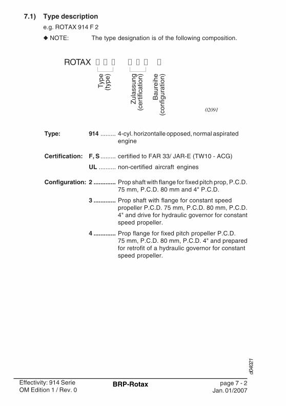
7.1) Type description
e.g. ROTAX 914 F 2
◆ NOTE: The type designation is of the following composition.
Type: 914 ......... 4-cyl. horizontalle opposed, normal aspiratedengine
Certification: F, S ......... certified to FAR 33/ JAR-E (TW10 - ACG)
UL .......... non-certified aircraft engines
Configuration: 2 ............. Prop shaft with flange for fixed pitch prop, P.C.D.75 mm, P.C.D. 80 mm and 4" P.C.D.
3 ............. Prop shaft with flange for constant speedpropeller P.C.D. 75 mm, P.C.D. 80 mm, P.C.D.4" and drive for hydraulic governor for constantspeed propeller.
4 ............. Prop flange for fixed pitch propeller P.C.D.75 mm, P.C.D. 80 mm, P.C.D. 4" and preparedfor retrofit of a hydraulic governor for constantspeed propeller.
02091

d040
21
page 7 - 3Jan. 01/2007
Effectivity: 914 SerieOM Edition 1 / Rev. 0
BRP-Rotax
7.2) Denomination of cylinders:
Top view
Lateral view
Cyl. 2 Cyl. 4
Cyl. 1 Cyl. 3
3
2
11
6
fig. 1
fig. 2
MAG
PTO5
4
1110
10
03644
03645
71

d040
21
page 7 - 4Jan. 01/2007
Effectivity: 914 SerieOM Edition 1 / Rev. 0
BRP-Rotax
front view
PTO power take off side
MS magneto side
Cyl. 1__________Cylinder 1
Cyl. 2__________Cylinder 2
(1) engine serial number
(2) CD carburetor
(3) propeller gearbox
(4) electric starter
(5) intake air distributor"Airbox"
(6) fuel pressure control"Airbox"
Cyl. 3__________Cylinder 3
Cyl. 4__________Cylinder 4
(7) expansion tank with excesspressure valve
(8) turbocharger
(9) exhaust system
(10) vacuum pump or hydraulicgovernor for constant speedpropeller
(11) external generator
8
9
fig. 303646

d040
22
page 8 - 1Jan. 01/2007
Effectivity: 914 SerieOM Edition 1 / Rev. 0
BRP-Rotax
8) Technical data
8.1) Dimensions
03116
8.2) Weights
◆ NOTE: The stated weights are dry weights (without operatingfluids)
with: carburetors, generator, ignition unit and oilcontainer, electric starter, stainless steel muffler,engine suspension frame, turbo charger andTCU (turbocharge control unit)
without: radiator and fuel pump
Equipment (optional):
External alternator: .................. 3,0 kg (6,6 lb)
Vacuum pump: ........................ 0,8 kg (1,8 lb)
Overload clutch: ...................... 1,7 kg (3,7 lb)
◆ NOTE: The overload clutch is installed on all certified aircraftengines and on non-certified aircraft engines of theconfiguration 3.
03117
Description 914 UL / FBore 79,5 mm (3,13 in.)
Stroke 61 mm (2,40 in.)Displacement 1211 cm3 (73,9 in3)Compression
ratio9,0 : 1
Weight in kg (lb) 914 UL 914 F
Configuration 2/4
71,7 (158) with overload clutch
70,0 (154) without clutch
71,7 (158)
Configuration 3 74,4 (164)
d040
22
page 8 - 2Jan. 01/2007
Effectivity: 914 SerieOM Edition 1 / Rev. 0
BRP-Rotax
03118
8.3) Fuel consumption
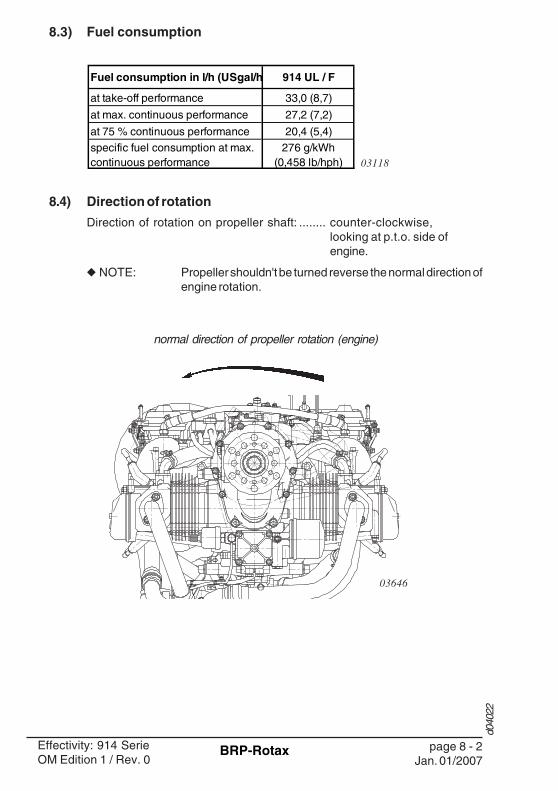
8.4) Direction of rotation
Direction of rotation on propeller shaft: ........ counter-clockwise,looking at p.t.o. side ofengine.
◆ NOTE: Propeller shouldn't be turned reverse the normal direction ofengine rotation.
normal direction of propeller rotation (engine)
03646
Fuel consumption in l/h (USgal/h 914 UL / F
at take-off performance 33,0 (8,7)
at max. continuous performance 27,2 (7,2)
at 75 % continuous performance 20,4 (5,4)specific fuel consumption at max. continuous performance
276 g/kWh (0,458 lb/hph)

d040
23
page 9 - 1Jan. 01/2007
Effectivity: 914 SerieOM Edition 1 / Rev. 0
BRP-Rotax
9) Description of systems
9.1) Cooling system
See fig. 4.
The cooling system of the ROTAX 914 is designed for liquid cooling of thecylinder heads and ram-air cooling of the cylinders. The cooling system of thecylinder heads is a closed circuit with an expansion tank.
The coolant flow is forced by a water pump, driven from the camshaft, fromthe radiator to the cylinder heads. From the top of the cylinder heads thecoolant passes on to the expansion tank (1). Since the standard location ofthe radiator (2) is below engine level, the expansion tank located on top of theengine allows for coolant expansion.
The expansion tank is closed by a pressure cap (3) (with excess pressurevalve and return valve). At temperature rise of the coolant the excesspressure valve opens and the coolant will flow via a hose at atmosphericpressure to the transparent overflow bottle (4). When cooling down, thecoolant will be sucked back into the cooling circuit.
◆ NOTE: Coolant temperatures are measured by means of tempera-ture probes installed in cylinder heads 2 and 3.
Readings are taken on measuring point of the hottest cylinder head, depend-ing on engine installation.
Coolant, see Chapter 10.2.1).
���������� �������� ������
������ � ��������
������������ � ��������� ����
fig. 4
4
1
3
2
08111
d040
23
page 9 - 2Jan. 01/2007
Effectivity: 914 SerieOM Edition 1 / Rev. 0
BRP-Rotax
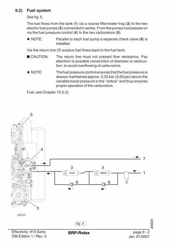
9.2) Fuel system
See fig. 5.
The fuel flows from the tank (1) via a coarse filter/water trap (2) to the twoelectric fuel pumps (3) connected in series. From the pumps fuel passes onvia the fuel pressure control (4) to the two carburetors (5).
◆ NOTE: Parallel to each fuel pump a separate check valve (6) isinstalled.
Via the return line (7) surplus fuel flows back to the fuel tank.
■ CAUTION: The return line must not present flow resistance. Payattention to possible constriction of diameter or obstruc-tion, to avoid overflowing of carburetors.
◆ NOTE: The fuel pressure control ensures that the fuel pressure isalways maintained approx. 0,25 bar (3,63 psi) above thevariable boost pressure in the "airbox" and thus ensuresproper operation of the carburetors.
Fuel, see Chapter 10.2.2).
fig. 5
AUX MAIN
5
5
00103
1
2
3 3
66
7
4

d040
23
page 9 - 3Jan. 01/2007
Effectivity: 914 SerieOM Edition 1 / Rev. 0
BRP-Rotax
9.3) Lubrication system
See fig. 6.
The ROTAX 914 engine is provided with a dry sump forced lubricationsystem with a main oil pump with integrated pressure regulator and anadditional suction pump.
◆ NOTE: The oil pumps are driven by the camshaft.
The main oil pump sucks the motor oil from the oil tank (1) via the oil cooler(2) and forces it through the oil filter to the points of lubrication (lubricates alsothe plain bearings of the turbo charger and the propeller governor).
The surplus oil emerging from the points of lubrication accumulates on thebottom of crankcase and is forced back to the oil tank by the blow-by gases.
The turbo charger is lubricated via a separate oil line (from the main oil pump.
The oil emerging from the lower placed turbo charger collects in the oil sumpby a separate pump and is pumped back to the oil tank via the oil line (3).
◆ NOTE: The oil circuit is vented via bore (5) in the oil tank.
◆ NOTE: There is an oil temperature sensor in the oil pump flange,for reading of the oil temperature.
Lubricants, see Chapter 10.2.3).
5 4
1
2 fig. 603649
3

d040
23
page 9 - 4Jan. 01/2007
Effectivity: 914 SerieOM Edition 1 / Rev. 0
BRP-Rotax
9.4) Electric system
See fig. 7.
The ROTAX 914 engine is equipped with a dual ignition unit of a breakerless,capacitor discharge design, with an integrated generator.
The ignition unit is completely free of maintenance and needs no externalpower supply.
Two independent charging coils (1) located on the generator stator supply oneignition circuit each. The energy is stored in capacitors of the electronicmodules (2). At the moment of ignition 2 each of the 4 external trigger coils (3)actuate the discharge of the capacitors via the primary circuit of the dualignition coils (4).
Firing order: 1-4-2-3.
◆ NOTE: The 5th trigger coil (5) is planned for rev. counter signal.
3
5
3
24
B1/
2
A3/4
B3/
4
A1/2
1
2
4
4
4
3
3
Ignition circuit A
Ignition circuit B
fig. 7
03043

d040
23
page 9 - 5Jan. 01/2007
Effectivity: 914 SerieOM Edition 1 / Rev. 0
BRP-Rotax
9.5) Turbo charge and control system
See fig. 8 and 9.
The ROTAX 914 engine is equipped with an exhaust gas turbo charger,making use of the energy in the exhaust gas for precompression of the intakeair (boost pressure).
The boost pressure in the airbox is controlled by means of an electronicallycontrolled flap (wastegate) in the exhaust gas turbine.
◆ NOTE: The wastegate regulates the speed of the turbo charger andconsequently the boost pressure in the airbox.
The required nominal boost pressure in the airbox is determined by the throttleposition sensor mounted on the carburetor 2/4. The sensor's transmittedposition is linear from 0 to 115% corre-sponding to a throttle position from idle tofull power. See fig. 8.
For correlation between throttle positionand nominal boost pressure in the airbox,refer to the diagram (fig. 9).
28
1400
1300
1200
1100
1000
900
hPa
0 10 20 30 40 50 60 7 0 80 90 100 110 115 %
30
32
34
36
38
46 in. HG
1500
40
42
44
100%
115%
0%
fig. 8
fig. 9
00170
03119
03044
The most important points for engine operation:
◆ NOTE: In the course of model refinement some parameters havebeen slightly changed. Diagram and table show the currentstate of software.
■ CAUTION: As shown in the diagram, the throttle position at 108 ÷ 110% results in a rapid rise of nominal boost pressure. To avoidunstable boost, the throttle should be moved smoothlythrough this area either to full power (115 %) or, on a powerreduction, to max. continuous power.
engine performance throttle position nominal airbox pressure
idling of engine ~ 0 % 1500 hPa (44,3 in. HG)max. continuous performance 100 ÷ 108 % 1220 hPa (36,0 in. HG)take-off performance 110 ÷ 115 % 1370 hPa (40,5 in.HG)

d040
23
page 9 - 6Jan. 01/2007
Effectivity: 914 SerieOM Edition 1 / Rev. 0
BRP-Rotax
In this range (108 - 110 % throttle position) small changes in throttle positionhave a big effect on engine performance and speed, but are virtually notapparent for the pilot from the throttle lever position.
■ CAUTION: The exact setting for a specific performance is virtuallyimpossible in this range and has to be prevented, as it mightcause control fluctuations (surging).
Besides the throttle position, overspeeding of the engine and too high intakeair temperature have an effect on the nominal boost pressure.If one of the stated factors exceeds the specified limits, the boost pressure isautomatically reduced, thus protecting the engine against overload.
The TCU (Turbo Control Unit) is furnished additionally with output connectionsfor an external "red" boost lamp and an "orange" caution lamp for indicationof function of the TCU.
When switching on the voltage supply, the two lamps are automatically subjectto a function test. Both lamps illuminate for 1 - 2 seconds, then they extinguish.If they do not, a check as per Maintenance Manual is necessary.
▲ WARNING: The engine must not be taken into operation before havingcorrected the cause of deficiency.
Orange caution lamp:
The non-illuminated orange caution lamp signals that TCU is ready foroperation.
If the lamp is blinking, this indicates a malfunction of the TCU or its periphery.See Chapter 10.4.6.
Red boost lamp:
— Exceeding of the admissible boost pressure will activate the red boostlamp, being continuously illuminated (see Chapter 10.4.4).
— The TCU registers the time of full throttle operation (boost pressure). Fullthrottle operation for longer than 5 minutes will make the red boost lampblinking. See Chapter 10.4.5).
■ CAUTION: The red boost lamp helps the pilot to avoid full poweroperation for longer than 5 minutes as otherwise the enginewould be thermally and mechanically overstressed.

d040
23
page 9 - 7Jan. 01/2007
Effectivity: 914 SerieOM Edition 1 / Rev. 0
BRP-Rotax
9.6) Propeller gearbox
See fig. 10.
For the engine type 914 two reduction ratios are available.
Depending on engine type, certification and configuration the propeller gear-box is supplied with or without an overload clutch.
◆ NOTE: The overload clutch is installed on serial production on allcertified aircraft engines and on the non-certified aircraftengines of configuration 3.
◆ NOTE: Fig. 10 shows a propeller gearbox of configuration 2 with theintegrated overload clutch.
The design incorporates a torsional shock absorber. The shock absorbing isbased on progressive torsional cushioning due to axial spring load acting ona dog hub.
On the gearbox version with overload clutch the design incorporates a frictiondamped free play at the dogs to warrant proper engine idling.Due to this backlash at the dogs a distinct torsional impact arises at start, stopand at sudden load changes, but due to the built-in overload clutch it will remainharmless.
◆ NOTE: This overload clutch will also prevent any undue load to thecrankshaft in case of ground contact of the propeller.
Alternatively either a vacuum pump or a hydraulic governor for constantspeed propeller can be used. The drive is in each case via the propellerreduction gear.
02531fig. 10
03120
reduction ratio 914 UL/F
crankshaft : propeller shaft 2,43 : 1

d040
23
page 9 - 8Jan. 01/2007
Effectivity: 914 SerieOM Edition 1 / Rev. 0
BRP-Rotax
9.6.1) Hydr. governor for const. speed propeller, vacuum pump:
Alternatively either a vacuum pump or a hydraulic governor forconstant speed propeller can be used. The drive is in each case viathe propeller reduction gear.
Gear ratio:
03121
◆ NOTE: Transmission ratio between crankshaft and hy-draulic governor or vacuum pump is 1,842 i.e. thespeed of the hydraulic governor or vacuum pumpis 0,54 of engine speed.
gear ratio
crankshaft : propeller shaft 2,43 : 1
propeller shaft : hydraulic governor/vacuum pump 0,758 : 1
crankshaft : hydraulic governor/vacuum pump 1,842 : 1

d040
24
page 10 - 1Jan. 01/2007
Effectivity: 914 SerieOM Edition 1 / Rev. 0
BRP-Rotax
10)Operating instructionsThe data of the certified engines are based on type certificate of type 914 F(TW10 - ACG).
10.1) General limits of operation10.1.1) Operating speeds and limits
1. Speed:Take-off speed ............................ 5800 rpm (5 min.)Max. continuous speed ............... 5500 rpmIdle speed ................................... approx. 1400 rpm
2. Manifold pressure:Take-off performance .................. max. 1350 hPa (39,9 in.HG)Max. continuous performance ..... max. 1200 hPa (35,4 in.HG)■ CAUTION: Due to the control behavior an overshooting of the
manifold pressure is possible. But within 2 secondsthis pressure has to stabilize within the allowance.
3. Acceleration:Limit of engine operation at zero gravity and in negative "g" condi-tions
max. ............................................ 5 seconds at max. -0,5 g
4. Critical flying altitude:Take-off performance .................. up to max. 2450 m (8000 ft.)
above sea levelContinuous performance ............. up to max. 4500 m (16000 ft.)
above sea level■ CAUTION: Up to the stated critical flight altitude the respective
manifold pressure is available.
5. Oil pressure:max. ............................................ 7 bar (102 psi)■ CAUTION: For a short period admissible at cold start.min. ............................................. 0,8 bar (12 psi) (below 3500 rpm)
*1,5 bar (22 psi)normal ......................................... 2,0 ÷ 5,0 bar (29 ÷ 73 psi) (above
3500 rpm)
*1,5 ÷ *5,0 bar (22 ÷ 73 psi)
*914 UL starting with S/N 4,417.665
* 914 F starting with S/N 4,420.0856. Oil temperature:
max. ............................................ 130 °C ................. (266 °F)min. ............................................. 50 °C .................... (120 °F)normal operating temperature ...... approx. 90 ÷ 110 °C (190÷230 °F)

d040
24
page 10 - 2Jan. 01/2007
Effectivity: 914 SerieOM Edition 1 / Rev. 0
BRP-Rotax
7. CoolantSee Operating media Chapter 10.2.1
- In use of conventional coolant:
Coolant temperature: (coolant exit temperature)
max.....................................................120 °C (248 °F)
Cylinder head temperature:
max.....................................................135 °C (275 °F)
Permanent monitoring of coolant temperature and cylinder headtemperature is necessary.
- In use of waterless coolant:
Cylinder head temperature:
max.....................................................135 °C (275 °F)
Permanent monitoring of cylinder head temperature is necessary.
8. Airbox temperature:
* intervention temperature ............. 72 °C (160° F)
* intervention temperature ............. 88 °C (190° F)
* 914 UL commencing with S/N 4,417.598 (TCU partno. 966 471)
* 914 F commencing with S/N 4,420.200 (TCU partno. 966 741)
9. Fuel pressure:max. .................................... Airbox pressure + 0,35 bar (5,08 psi)min. ..................................... Airbox pressure + 0,15 bar (2,18 psi)normal ................................. Airbox pressure + 0,25 bar (3,63 psi)◆ NOTE: Exceeding the max. admissible fuel pressure will
override the float valve of the carburetor.10. Power consumption of the hydraulic propeller governor:
max. ............................................ 600 W11. Power consumption of the vacuum pump:
max. ............................................ 300 W12. Power consumption of the external alternator:
max. ............................................ 1200 W13. Deviation from bank angle
max. ............................................ 40°◆ NOTE: Up to this value the dry sump lubrication system
warrants lubrication in every flight situation.

d040
24
page 10 - 3Jan. 01/2007
Effectivity: 914 SerieOM Edition 1 / Rev. 0
BRP-Rotax
10.1.1.1) Performance graphs for standard conditions ISA(International Standard Atmosphere)
Take-off performance .................. 84,5 kW at 5800 rpm 1300 hPa (38,4 in.HG)
* 1320 hPa (39,0 in.HG)Max. continuous performance ..... 73,5 kW at 5500 1/min
1150 hPa (34,0 in.HG)
* 1180 hPa (34,9 in.HG)◆ NOTE: The stated pressure in the suction tube is always
lower by the pressure loss in the carburetors thanthe TCU controlled airbox pressure and may betherefore subject to bigger deviations.
* 914 UL starting with engine no. 4,417.598 (TCU partno. 966 471)
* 914 F starting with engine no. 4,420.200 (TCU partno. 966 741)

d040
24
page 10 - 4Jan. 01/2007
Effectivity: 914 SerieOM Edition 1 / Rev. 0
BRP-Rotax
fig. 11
3000 550050004500400035002500
80
70
60
50
40
30
20
0
10
5800 1/min
85kW
80
70
60
50
40
30
20
0
10
90
100
110
120 hp
3000
550050004500400035002500600
700
800
900
1000
1100
1200
1300
1400
5800 1/min
34
32
30
28
26
24
20
18
36
38
40
42 in. HGh Pa
3000
22
A
B
C
A
B
C
0
5
10
15
20
25
30
5500500045004000350030002500 5800 1/min
7
6
5
4
3
2
0
1
9 US gal/h
l/h
A
B
C
35
8C
A: Engine curve (take-off performance)B: Engine curve (continuous full throttle performance)C: Propeller curve (power requirement of propeller)
Engine performance
Manifold pressure
Fuel consumption

d040
24
page 10 - 5Jan. 01/2007
Effectivity: 914 SerieOM Edition 1 / Rev. 0
BRP-Rotax
Performance data for variable pitch propeller:
Engine operation is permitted without restriction between full throttle perfor-mance and power requirement of propeller, providing engine speed over 5500r.p.m. is restricted to 5 minutes.
However, for economic reasons it is recommended to run the engine inaccordance with the following table:
03122
Power-SettingEngine speed
[rpm]Performance
[kW]Manifold pres.
[in.HG]Throttle position
[%]
Take-off power 5800 84,5 139 102 39 115,0
max. continuous power
5500 73,5 128 93 35 100,0
75% 5000 55,1 105 77 31 approx. 6765% 4800 47,8 95 69 29 approx. 6455% 4300 40,4 90 65 28 approx. 59
Torque [Nm][ft.lb.]

d040
24
page 10 - 6Jan. 01/2007
Effectivity: 914 SerieOM Edition 1 / Rev. 0
BRP-Rotax
10.1.1.2) Performance graph for non-standard conditions
Exa
mp
le:
Max
. co
nti
nu
ou
s p
ow
er a
t 10
000
ft?
Tem
pera
ture
ISA
at 1
0 00
0 ft
......
......
......
......
......
......
......
......
......
.....
-5 °
CA
mbi
ent t
empe
ratu
re a
t 10
000
ft...
......
......
......
......
......
......
......
......
..-1
5 °C
Tem
pera
ture
diff
eren
ce to
ISA
......
......
......
......
......
......
......
......
......
....-
10 °
C
Max
. co
nti
nu
ou
s p
ow
er a
s p
er d
iag
ram
......
......
......
......
......
......
...72
kW
0312
3
fig. 12Alt
itu
de
(ft)
(°C
)(°
K)
-45
-40
-35
-30
-25
-20
-15
-10
-50
510
1520
2530
35-2
000
1929
210
199
9795
9492
9089
8786
8483
8180
7978
760
1528
810
098
9694
9391
8988
8685
8382
8079
7877
2000
1128
499
9795
9392
9088
8785
8482
8179
7877
7640
007
280
9896
9492
9189
8786
8483
8180
7877
7660
003
276
9795
9391
9088
8685
8381
8079
7776
8000
-127
296
9492
9088
8785
8382
8079
7876
Alt
itu
de
(ft)
(°C
)(°
K)
-45
-40
-35
-30
-25
-20
-15
-10
-50
510
1520
2530
35-2
000
1929
288
8685
8381
8078
7776
7473
7271
7069
6766
015
288
8785
8482
8079
7876
7574
7271
7069
6867
6620
0011
284
8785
8381
8078
7776
7473
7270
6968
6766
6540
007
280
8684
8281
7978
7675
7372
7170
6867
6665
6460
003
276
8583
8280
7877
7574
7371
7069
6866
6564
8000
-127
284
8281
7977
7674
7372
7069
6867
6664
6310
000
-526
883
8280
7877
7574
7271
6968
6766
6563
1200
0-9
264
8281
7977
7674
7271
7068
6766
6564
1400
0-1
326
081
7977
7674
7371
7068
6766
6563
1600
0-1
725
680
7876
7573
7270
6967
6665
64
Tem
per
atu
reIS
A
Tem
per
atu
reIS
A
Take
-off
per
form
ance
(kW
)
Max
.Co
nti
nu
ou
s p
ow
er (
kW)
Tem
per
atu
re d
iffe
ren
ce t
o IS
A
Tem
per
atu
re d
iffe
ren
ce t
o IS
A

d040
24
page 10 - 7Jan. 01/2007
Effectivity: 914 SerieOM Edition 1 / Rev. 0
BRP-Rotax
10.2) Operating media
10.2.1) Coolant
In principle, 2 different types of coolant are permitted.
- Conventional coolant based on ethylene glycol
- Waterless coolant based on propylene glycol
■ CAUTION: Obey the manufacturer's instructions about thecoolant.
Conventional coolant mixed with water has the advantage of ahigher specific thermal capacity than waterless coolant.
◆ NOTE: The important advantage of waterless coolant isits higher boiling point than a conventional mix-ture.
When correctly applied, there is sufficient protection against vaporbubble formation, freezing or thickening of the coolant within theoperating limits.
Use the coolant specified in the manufacturer's documentation.
■ CAUTION: Obey the latest edition of Service InstructionSI-914-019 for the selection of the correct coolant.
07032
designation concentrate water
conventional e.g. BASF Glysantine anticorrosion 50 50waterless e.g. EVANS NPG+ 100 0
mixture ratio %

d040
24
page 10 - 8Jan. 01/2007
Effectivity: 914 SerieOM Edition 1 / Rev. 0
BRP-Rotax
10.2.2) Fuel
The following fuels can be used.
1) min. ROZ 952) min. AKI 91
AVGAS 100LL places greater stress on the valve seats due to its highlead content and forms increased deposits in the combustion cham-ber and lead sediments in the oil system. Thus it should only be usedin case of problems with vapor lock or when other types of gasolineare unavailable.
■ CAUTION: Use only fuel suitable for the respective climaticzone.
◆ NOTE: Risk of vapour formation if using winter fuel forsummer operation.
■ CAUTION: Obey the latest edition of Service InstructionSI-914-019 for the selection of the correct fuel.
08316
Usage / Description
914 UL / F
EN 228 Super 1)
EN 228 Super plus1)
US standard ASTM D4814
US standard AVGAS 100 LL (ASTM D910)
MOGAS
AVGAS
European standard
Canadian standard
CAN/CGSB-3.5 Quality 3 2)

d040
24
page 10 - 9Jan. 01/2007
Effectivity: 914 SerieOM Edition 1 / Rev. 0
BRP-Rotax
10.2.3) Lubricants
Oil: Motorcycle oil of a registered brand with gear additi-ves. If using aircraft engine oil; than only blended one.
■ CAUTION: At the selection of suitable lubricants refer to theadditional information in the Service InformationSI-914-019, current issue.
Oil specification
— Use only oil with API classification "SG" or higher!
— Due to the high stresses in the reduction gears, oils with gearadditives such as high performance motor cycle oils are re-quired.
— Because of the incorporated friction clutch, oils with frictionmodifier additives are unsuitable as this could result in a slippingclutch during normal operation.
— Heavy dury 4-stroke motor cycle oils meet all the requirements.These oils are normally no mineral oils but semi- or full syntheticoils.
— Oils primarity for Diesel engines are due to insufficient hightemperature properties and additives which favour clutchslipping, generally unsuitable.
■ CAUTION: If the engine is mainly run on AVGAS morefrequent oil changes will be required. See Ser-vice Information SI-914-019, current issue.

d040
24
page 10 - 10Jan. 01/2007
Effectivity: 914 SerieOM Edition 1 / Rev. 0
BRP-Rotax
Klima
(climaticconditions)
tropisch(tropical)
gemäßigt
(temperate)
arktisch(arctic)
SA
E 2
0W-5
0
SA
E 1
5W-5
0
SA
E 1
0W-4
0
SA
E 5
W-5
0S
AE
5W
-40
SA
E 1
5W-4
0
SA
E 2
0W-4
0
Mehrbereichs-Öle
multi-grade oils
40
30
20
10
0
10
20
30 20
0
20
40
60
80
100
°C °F
fig. 13 01176
Oil consumption: ........... max 0,06 l/h (0.13 liq pt/h)
Oil viscosity:
Use of multi-grade oils is recommended.
◆ NOTE: Multi-viscosity grade oils are less sensitive totemperature variations than single grade oils.They are suitable for use throughout the seasons,ensure rapid lubrication of all engine componentsat cold start and get less fluid at higher tempera-tures.
Table of lubricants (See fig. 13)
Since the temperature range of neighbouring SAE grades overlap,there is no need for change of oil viscosity at short duration of ambienttemperature fluctuations.

d040
24
page 10 - 11Jan. 01/2007
Effectivity: 914 SerieOM Edition 1 / Rev. 0
BRP-Rotax
NOTES

d040
24
page 10 - 12Jan. 01/2007
Effectivity: 914 SerieOM Edition 1 / Rev. 0
BRP-Rotax
10.3) Standard operation
To warrant reliability and efficiency of the engine, meet and carefully observeall the operating and maintenance instructions.
10.3.1) Daily checks
▲ WARNING: Risk of burnings and scalds!Conduct checks on the cold engine only!
▲ WARNING: Ignition "OFF". Before cranking the propeller switchoff both ignition circuits and anchor the aircraft. Havethe cockpit occupied by a competent person.
■ CAUTION: If established abnormalities (e.g. excessive re-sistance of the engine, noises etc.) inspection inaccordance with the relevant Maintenance Manualis necessary. Do not release the engine intoservice before rectification.
Coolant level:
■ CAUTION: The coolant specifications of the section 10.2 Op-erating media are to be observed.
— Verify coolant level in the expansion tank, replenish as requiredup to top.
The coolant level must be at least 2/3 of the expansion tank.
— Verify coolant level in the overflow bottle, replenish as required.
The coolant level must be between max. and min. mark or at least0.2 litre (0.4 liq pt).
Check of mechanical components:
Turn propeller by hand in direction of engine rotation several timesand observe engine for odd noises or excessive resistance andnormal compression.

d040
24
page 10 - 13Jan. 01/2007
Effectivity: 914 SerieOM Edition 1 / Rev. 0
BRP-Rotax
Gear box:
— Version without overload clutch:
No further checks are necessary.
— Version with overload clutch:
Turn the propeller by hand to and fro, feeling the free rotation of 15° or 30 ° before the crankshaft starts to rotate.
If the propeller can be turned between the dogs with practically nofriction at all (less than 25 Nm / 222 in.lb) further investigation isnecessary.
Carburetor:
— Verify free movement of throttle cable and starting carburetorover the complete range. Check from the cockpit.
Exhaust system and trubocharger:
— Inspect for cracks, damages, leakage and general condition.

d040
24
page 10 - 14Jan. 01/2007
Effectivity: 914 SerieOM Edition 1 / Rev. 0
BRP-Rotax
10.3.2) Before engine start
Carry out pre-flight checks.
10.3.3) Pre-flight checks
▲ WARNING: Ignition "OFF" Before cranking the propellerswitch off both ignition circuits and anchor theaircraft. Have the cockpit occupied by a compe-tent person.
Operating media:
▲ WARNING: Carry out pre-flight checks on the cold or lukewarm engine only! Risk of burning and scalds.
Check for any oil-, coolant- and fuel leaks.
If leaks are evident, rectify before flight.
■ CAUTION: The coolant specifications of the section 10.2 Op-erating media are to be observed.
— Verify coolant level in the overflow bottle, replenish as required.
The coolant level must be between min. and max. mark or at least0.2 litre (0.4 liq pt).
■ CAUTION: The oil specifications of the section 10.2 Operatingmedia are to be observed.
— Check oil level and replenish as required.
◆ NOTE: Propeller shouldn't be turned reverse the normaldirection of engine rotation.
— Prior to oil check, turn the propeller by hand in direction of enginerotation several times to pump oil from the engine into the oil tank,or let the engine idle for 1 minute.
This process is finished when air is returning back to the oil tankand can be noticed by a murmur from the open oil tank.
◆ NOTE: Oil level should be between max. and min. mark ofthe oil level gauge but must never be below min.mark. Before longer periods of operation ensurethat oil level is at least up to mid-position.
Difference between max.- and min.- mark = 0,45 litre (0.95 liq pt)

d040
24
page 10 - 15Jan. 01/2007
Effectivity: 914 SerieOM Edition 1 / Rev. 0
BRP-Rotax
10.3.4) Engine start
▲ WARNING! Do not take the engine into operation if any personis near the aircraft.
Fuel cock. ................................... open
Starting carb. ............................. activated
◆ NOTE: If the engine is already in operating temperature,start the engine without choke.
Throttle lever. ............................ set to idle position
Master switch. ........................... on
Function test of TCU:
◆ NOTE: When switching on the voltage supply, both lampsare automatically subject to a function test.
For approx. 1 - 2 seconds both lamps illuminate and then extinguish.If not, a check as per Maintenance Manual is necessary.
▲ WARNING: Do not take the engine into operation beforehaving rectified the cause of deficiency.
electric fuel pump ..................... on
Ignition. ...................................... both circuits switched on
Starter button. ........................... actuate
■ CAUTION: Activate starter for max. 10 sec. only (withoutinterruption), followed by a cooling period of 2minutes!
As soon as engine runs, adjust throttle to achieve smooth running atapprox. 2500 r.p.m.
Check if oil pressure has risen within 10 seconds and monitor oilpressure. Increase of engine speed is only permitted at steady oilpressure readings above 2 bar (30 psi).
At an engine start with low oil temperature, continue to observe theoil pressure as it could drop again due to the increased flowresistance in the suction line. The number of revolutions may be onlyso far increased that the oil pressure remains steady.
De-activate starting carb.
■ CAUTION: Since the engine comprises a reduction gear withshock absorber, take special care of the follow-ing:
To prevent impact load, start with throttle lever inidle position or at the most up to 10% open.

d040
24
page 10 - 16Jan. 01/2007
Effectivity: 914 SerieOM Edition 1 / Rev. 0
BRP-Rotax
For the same reason, wait for around 3 sec. afterthrottling back to partial load to reach constantspeed before re-acceleration.
For checking the two ignition circuits, only onecircuit may be switched off and on at times.
■ CAUTION: Do not actuate starter button (switch) as long asthe engine is running. Wait until complete stop ofengine!

d040
24
page 10 - 17Jan. 01/2007
Effectivity: 914 SerieOM Edition 1 / Rev. 0
BRP-Rotax
10.3.5) Prior to take-off
Warming up period:
Start warming up period at 2000 r.p.m. for approx. 2 minutes, continueat 2500 r.p.m., duration depending on ambient temperature, until oiltemperature reaches 50 °C (120° F).
— Check temperatures and pressures.
Throttle response:
— Short full throttle ground test (consult Aircraft Operator's Manualsince engine speed depends on the propeller used).
■ CAUTION: After a full-load ground test allow a short coolingrun to prevent vapour formation in the cylinderhead.
Ignition check:
Check the two ignition circuits at 4000 r.p.m. (approx. 1700 r.p.m.propeller).
— Speed drop with only one ignition circuit must not exceed 300r.p.m. (approx. 130 r.p.m. propeller).
— 115 r.p.m. (approx. 50 r.p.m. propeller) max. difference of speedby use of either circuit, A or B.
◆ NOTE: The propeller speed depends on the actual reduc-tion ratio.
Check of hydraulic propeller governor:
Check control of the hydraulic propeller governor to specifications ofthe manufacturer.

d040
24
page 10 - 18Jan. 01/2007
Effectivity: 914 SerieOM Edition 1 / Rev. 0
BRP-Rotax
10.3.6) Take-off
■ CAUTION: If the national Aviation Authority demands the soft-ware classification "D" according to RTCA DO 178B for the TCU software a special starting proce-dure is laid down which renders any influence ofthe TCU ineffective during the take-off, see section10.3.6.2).
Climbing with engine running at take-off performance is permissible(max. 5 minutes). See Chapter 10.1), 10.1.1) and 10.1.2).
▲ WARNING: Monitor oil temperature, cylinder head temperatureand oil pressure. Limits must not be exceeded!See Chapter 10.1) Operating Limits.
■ CAUTION: Respect "cold weather operation" recommenda-tions, see Chapter 10.3.9).
10.3.6.1) Take-off (standard - with active TCU)
— Switch on the auxiliary fuel pump at take-off.— Switch throttle lever to 115 % (take-off performance).— The auxiliary fuel should be switched off after the take-off.
10.3.6.2) Take-off (as per RTCA DO 178 B - with inactive TCU)
— Take-off performance until the boost pressure stabilizeswithin the limits of operation.
— TCU-switch in "OFF" position.
— Switch on the auxiliary fuel pump at take-off.
— Shift throttle lever to 115 % (take-off performance).
— After reaching the critical altitude switch on the TCU.
■ CAUTION: Any improper use of the TCU-switch will be re-corded by the TCU. At exceeding of the limits ofoperation will render any claims on Rotax null andvoid.
— The auxiliary fuel pump may be switched off after thetake-off.

d040
24
page 10 - 19Jan. 01/2007
Effectivity: 914 SerieOM Edition 1 / Rev. 0
BRP-Rotax
10.3.7) Cruising
Set performance as per performance specifications and respectoperating limits as per Chapter 10.1), 10.1.1) and 10.1.2).
Avoid operation below normal operation oil temperature (90 ÷110 °C/ 194 ÷ 230 °F), as possible formation of condensation water in thelubrication system badly influences the oil quality.
To evaporate possibly accumulated condensation water, at leastonce a day 100 °C (212°F) oil temperature must be reached.
10.3.8) Engine shut-off
Normally the cooling down of the engine during descending andtaxiing will be sufficient to allow the engine to be shut off as soon asthe aircraft is stopped.
At increased operating temperatures to make an engine cooling runof at minimum 2 minutes.

d040
24
page 10 - 20Jan. 01/2007
Effectivity: 914 SerieOM Edition 1 / Rev. 0
BRP-Rotax
10.3.9) Cold weather operation
Generally, an engine service should be carried out before the start ofthe cold season.
Coolant:
For selection of coolant and mixing ratio, see "Coolant", Chapter10.2.1).
Lubricant:
For selection of oil, see Table of Lubricants (Chapter 10.2.3).
Cold start:
— With throttle closed and choke activated (open throttle rendersstarting carb ineffective).
— Be aware, no spark below crankshaft speed of 220 rpm. (propel-ler speed of 90 rpm.).
— As performance of electric starter is greatly reduced when hot,limit starting to periods not much longer than 10 sec. With a wellcharged battery, adding a second battery will not improve coldstarts.
Remedy:
— Use of multigrade oil with the low end viscosity code of 5 or 10.
— Gap electrode on spark plug to the minimum or fit new sparkplugs.
— Preheat engine using hot air.

d040
24
page 10 - 21Jan. 01/2007
Effectivity: 914 SerieOM Edition 1 / Rev. 0
BRP-Rotax
Beyond that observe following advices for operation at extremely lowtemperatures:
◆ NOTE: Distinguish between two kinds of carb icing:
1) Icing due to water in fuel
2) Icing because of high air humidity
Addendum to note 1)
Water in fuel will accumulate at the lower parts of the fuel system andleads to freezing of fuel lines, filters or jets.
Remedy:
— Use non-contaminated fuel (filtered through suède)
— Generously sized water separators
— Fuel lines routing inclined
— Prevent condensation of humidity, i.e. avoid temperature differ-ences between aircraft and fuel.
▲ WARNING: Fuels containing alcohol always carry a smallamount of water in solution. In case of temperaturechanges or increase of alcohol content, water or amixture of alcohol and water may settle and couldcause troubles.
Addendum to note 2)
Carburetor icing due to humidity may occur on the venturi and on thethrottle valve due to fuel evaporation and leads to performance lossand change in mixture. Intake air pre-heating is the only effectiveremedy.

d040
24
page 10 - 22Jan. 01/2007
Effectivity: 914 SerieOM Edition 1 / Rev. 0
BRP-Rotax
10.4) Abnormal operation
▲▲▲▲▲ WARNING: At unusual engine behaviour conduct checks as perChapter 10.4.1) through 10.4.13) below, and as perMaintenance Manual before the next flight.
◆ NOTE: Further checks - see Maintenance Manual.
10.4.1) Sudden drop of boost pressure and speed
— Loud noise or bang:
A fracture of the turbo is likely.
Look for landing possibility. Flight with reduced performance maybe possible. Monitor oil pressure.
— The orange caution lamp of TCU (turbo control unit) is blinking.
Limited flying operation as possibly wastegate does not close anymore.
■ NOTE: A minimum performance of approx. 66 kW remainsavailable.
Any exceeding of the max. admissible operating limits and/or blinkingof orange caution lamp must be recorded by the pilot in the logbook,stating the duration, exact time and extent of exceeding.
10.4.2) Sudden rise of boost pressure and speed
— Orange caution lamp of TCU is blinking:
Immediately reduce engine speed until boost pressure and speedare within operating limits.
Limited flying operation as wastegate may be fully closed andcontrol of the boost pressure is only possible via throttle lever.
— Bowden cable(s) for actuation of throttle valve(s) broken:
Due to spring pressure the throttle valve(s) will be fully open - fullthrottle!
Limited flying operation as wastegate may be fully closed andcontrol of the boost pressure is only possible via throttle lever.
Any exceeding of the max. admissible engine speed or boost pres-sure has to be recorded by the pilot in the logbook, stating theduration, exact time and extent of exceeding.
d040
24
page 10 - 23Jan. 01/2007
Effectivity: 914 SerieOM Edition 1 / Rev. 0
BRP-Rotax
10.4.3) Periodical rise and drop of boost pressure and speed (boostpressure control is surging)
Orange caution lamp of TCU is not blinking.
Switch off servo motor for a moment (max. 5 sec.). After a shortregulating time operation should stabilize.
■ CAUTION: If this action does not stabilize operation, swith offservo motor completely. If need be, reduce enginespeed until boost pressure and speed are withinthe operating limits again.
Limited flying operation, as boost pressure control is no more pos-sible.
Switching off the servo motor momentarily or permanently, has to berecorded by the pilot in the logbook, stating the duration, exact timeand duration of switching off.
10.4.4) Red boost lamp of TCU permanently illuminating
The maximum admissible boost pressure was exceeded.
Reduce speed and boost pressure manually to be within the operat-ing limits.
Limited flying operation, as boost pressure control is no more orinsufficiently possible.
■ CAUTION: The boost pressure will not be reduced automati-cally.
In case of exceeding the max. admissible boost pressure, this has tobe recorded by the pilot in the logbook, stating the duration and exacttime of exceeding of limits.
10.4.5) Red boost lamp of TCU blinking
The maximum "take-off" time limitation was exceeded.
Reduce speed and boost pressure at least to maximum continuousspeed.
■ CAUTION: The boost pressure will not be reduced automati-cally.
In case of exceeding the "take-off" time limits, this has to be recordedby the pilot in the logbook, stating the duration and exact time ofexceeding of limits.

d040
24
page 10 - 24Jan. 01/2007
Effectivity: 914 SerieOM Edition 1 / Rev. 0
BRP-Rotax
10.4.6) Orange caution lamp of TCU blinking
Indicates a failure of a sensor, sensor wiring, TCU, or leakage in theairbox.
Reduce speed and boost pressure manually to be within the operat-ing limits.
Limited flying operation, as this may indicate that boost pressurecontrol is no more or insufficiently possible and may affect engineperformance.
In case of blinking of the orange caution lamp of TCU, this has to berecorded by the pilot in the logbook, stating the duration, exact timeand extent of exceeding limits.
10.4.7) Failure of the voltage supply to the TCU
At a failure of voltage supply the servo motor will remain in itsmomentary position.
Limited flight operation as boost pressure control is not possible anymore.
Any exceeding of the max. admissible operating limits must berecorded by the pilot in the logbook, stating the duration, exact timeand extent of exceeding.
10.4.8) Engine stop - Start during flight
Starting procedure same as on ground, however, on a warm enginewithout choke.
10.4.9) Exceeding of max. admissible engine speed
Reduce engine speed. Any exceeding of the max. admissible enginespeed has to be entered by the pilot into the logbook, stating durationand extent of overspeed.
10.4.10) Exceeding of max. admissible cyl. head temperature
▲ WARNING: Reduce engine power setting to the minimum nec-essary and carry out precautionary landing.
Any exceeding of the max. admissible cylinder head temperature hasto be entered by the pilot into the logbook, stating duration and extentof over-temperature condition.

d040
24
page 10 - 25Jan. 01/2007
Effectivity: 914 SerieOM Edition 1 / Rev. 0
BRP-Rotax
10.4.11) Exceeding of max. admissible oil temperature
▲ WARNING: Reduce engine power setting to the minimum nec-essary and carry out precautionary landing.
Any exceeding of the max. oil temperature must be entered by thepilot in the logbook, stating duration and extent of over-temperaturecondition.
10.4.12) Oil pressure below minimum - during flight
▲ WARNING: Reduce engine power setting to the minimum nec-essary and carry out precautionary landing.
Check oil system.
10.4.13) Oil pressure below minimum - on ground
Immediately stop the engine and check for reason. Check oil system.
— Check oil quantity in oil tank.
— Check oil quality (see section 10.2.3).
10.4.14) Engine on fire of fire in the engine compartment
In the event of fire or signs, e.g. heavy smoke both electric fuel pumpsand the main switch must be switched off and the fuel tap has to beclosed.
If the fire should extinguish it may be tried again to actuate the mainfuel pumps and to start the engine (see section 10.3.4).
If the fire starts anew the fuel system has to be interrupted again atonce.
Any shut-off of the fuel system for short periods or permanent has tobe entered by the pilot into the logbook starting date and duration ofshut-off.

d040
24
page 10 - 26Jan. 01/2007
Effectivity: 914 SerieOM Edition 1 / Rev. 0
BRP-Rotax
NOTES

d004
25
page 11 - 1Jan. 01/2007
Effectivity: 914 SerieOM Edition 1 / Rev. 0
BRP-Rotax
11)ChecksAll checks to be carried out as specified in the current Maintenance Manual (lastrevision).
▲ WARNING: Only qualified staff (authorized by the Aviation Authorities)trained on this particular engine, is allowed to carry outmaintenance and repair work.
■ CAUTION: Carry out all directives of Service Bulletins, according to theirpriority.
11.1) Engine preservation
Due to the special material of the cylinder wall, there is no need for extraprotection against corrosion. At extreme climatic conditions and for long outof service periods we recommend the following to protect the valve guidesagainst corrosion:
– Let engine run until warm, then change oil.
– Remove the air intake filters and insert approx. 30 cm³ (1 fl oz) of corrosioninhibiting oil into the carburetor throat with the engine running at increasedidle speed. Shut off engine.
– Drain carburetor float chamber.
– Apply oil to all joints on carburetors.
– Close all openings on the cold engine, such as exhaust end pipe, ventingtube, air filter etc. against entry of dirt and humidity.
– Spray all steel external engine parts with corrosion inhibiting oil.
Engine back to operation
– Remove all plugs and fasteners.
– Clean spark plugs with plastic brush and solvent.
– If preservation including oil change took place within a year of storage, oilrenewal will not be necessary. For longer storage periods repeat preser-vation annually.

d004
25
page 11 - 2Jan. 01/2007
Effectivity: 914 SerieOM Edition 1 / Rev. 0
BRP-Rotax
NOTES

d004
26
page 12 - 1Jan. 01/2007
Effectivity: 914 SerieOM Edition 1 / Rev. 0
BRP-Rotax
Engine does not start
POSSIBLE CAUSE:
a - ignition off
b - closed fuel tap or clogged filter
c - no fuel in tank
d - starting speed too low, faulty ordischarged battery
e - starting speed too low, startproblems on cold engine
f - carb to rich
12)Trouble shooting▲ WARNING: Only qualified staff (authorized by the Aviation Authorities)
trained on this particular engine, is allowed to carry outmaintenance and repair work.
If the following hints regarding remedy do not solve theproblem, contact an authorized workshop. The engine mustnot be operated until the problem is rectified.
REMEDY:
switch on.
open tap, clean or renew filter,check fuel system for leaks.
refuel.
fit fully charged battery.
use top quality, low friction oil;allow for sufficient cooling periodto counter for performance dropon hot starter; pre-heat engine.
start without pumps
Engine idles rough after warm-up period, smoky exhaust emission
POSSIBLE CAUSE:
a - starting carb activated
Low oil pressure
POSSIBLE CAUSE:
a - not enough oil in oil tank
REMEDY:
close starting carb.
REMEDY:
check oil return line for free pas-sage, renew oil seal.

d004
26
page 12 - 2Jan. 01/2007
Effectivity: 914 SerieOM Edition 1 / Rev. 0
BRP-Rotax
POSSIBLE CAUSE:
a - overheating of engine
Engine keeps running with ignition off
Oil level is increasing
POSSIBLE CAUSE:
a - oil too cold during engine operation
Knocking under load
POSSIBLE CAUSE:
a - Octane rating of fuel too low
Engine hard to start at low temperature
POSSIBLE CAUSE:
a - starting speed too low
b - low charge battery
c - high oil pressure
d - oil pressure too low after cold start
REMEDY:
let engine cool down at idling atapprox. 2000 r.p.m.
REMEDY:
cover oil cooler surface, maintainthe oil temperature prescribed.
REMEDY:
use fuel with higher octane rating.
REMEDY:
preheat engine.
fit fully charged battery.
at cold start a pressure reading ofup to around 7 bar (102 psi) doesnot indicate a malfunction.
too much resistance in the oil suc-tion tube at low temperatures. Stopengine and preheat oil.
At oil pressure reading too low than1 bar oils with lower viscosity areto be used.
See SI-914-019, current issue.
◆ NOTE: Oil pressure must in the idle operationwith an oil temperature of min. 50 °C(120°F) to be measured.

d004
26
page 12 - 3Jan. 01/2007
Effectivity: 914 SerieOM Edition 1 / Rev. 0
BRP-Rotax
NOTES

d004
26
page 12 - 4Jan. 01/2007
Effectivity: 914 SerieOM Edition 1 / Rev. 0
BRP-Rotax
12.1) Reporting
According to the regulation of JAR / FAR 21.3 the manfacturer shall evaluatefield information and report to the authority. In case of any relevant occur-rences that may involve malfunction of the engine, the form on the next pageshould be filled out and sent to the responsible authorized ROTAX distributor.
◆ NOTE: The form is also available from the official ROTAX AIR-CRAFT ENGINES Homepage
www.rotax-aircraft-engines.com
in electronic version.

d004
26
page 12 - 5Jan. 01/2007
Effectivity: 914 SerieOM Edition 1 / Rev. 0
BRP-Rotax
CU
ST
OM
ER
SE
RV
ICE
INF
OR
MA
TIO
N R
EP
OR
T
OP
ER
. Co
ntr
ol N
o.
ATA
Co
de
A/C
Reg
. No
.
Ent
er p
ertin
ent d
ata
MA
NU
FAC
TU
RE
RM
OD
EL
/SE
RIE
SS
ER
IAL
NU
MB
ER
AIR
CR
AF
T
PO
WE
RP
LAN
T
PR
OP
ELL
ER
5.S
PE
CIF
IC P
AR
T (
of c
ompo
nent
)C
AU
SIN
G T
RO
UB
LE
Par
t Nam
eM
FG
. Mod
el o
r P
art N
o.S
eria
l No.
Par
t/Def
ect L
ocat
ion
4.3.2. 6.E
NG
INE
CO
MP
ON
EN
T (
Ass
embl
y th
at in
clud
es p
art)
Eng
ine/
Com
p. N
ame
Man
ufac
ture
rM
odel
or
Par
t No.
Ser
ial N
umbe
r
Eng
ine
TS
NE
ngin
e T
SO
Eng
ine
Con
ditio
n7.
Dat
e S
ub.
8.C
omm
ents
(D
escr
ibe
the
mal
func
tion
or d
efec
t and
the
circ
umst
ance
s un
der
whi
chit
occu
rred
. Sta
te p
roba
ble
caus
e an
d re
com
men
datio
ns to
pre
vent
rec
urre
nce.
)
Op
tio
nal
Info
rmat
ion
:C
heck
a b
ox b
elow
, if t
his
repo
rt is
rel
ated
to a
n ai
rcra
ft
Acc
iden
t; D
ate
Inci
dent
; Dat
e
TELEPHONENUMBER:()———
REP.STA
SUBMITTEDBY:
1.
Mus
ter
0R
OTA
X
A-Z
L1.
VR
DISTRICTOFFICE
OPERMECHAIRTAXIMFGACGCOMMUTEROTHER
OPERATORDESIGNATOR
AIR
CR
AF
T E
NG
INE
S

d004
26
page 12 - 6Jan. 01/2007
Effectivity: 914 SerieOM Edition 1 / Rev. 0
BRP-Rotax
NOTES

d040
27
page 13 - 1Jan. 01/2007
Effectivity: 914 SerieOM Edition 1 / Rev. 0
BRP-Rotax
13) Authorized Distributors for ROTAX® Aircraft Engineswww.rotax-aircraft-engines.com
Issue 01 01 20071) E U R O P E
AUSTRIA:➤➤➤➤➤HB - FLUGTECHNIK GMBH
Dr. Adolf Schärf Str. 42A-4053 HAIDTel.: +43 (0)7229 / 79104,Fax: +43 (0) 7229 / 79104 15E-mail: [email protected]: www.hb-flugtechnik.atContact person: Ing. Georg Passenbrunner
BULGARIA:
➤➤➤➤➤GERGANOV - AIRCRAFT ENGINES LTD.25B-Post 20, 23 peh. Shlp. polk Blvd.BG-6100 KAZANLAKTel.: +359 (0) 431 / 27 247,Fax: +359 (0) 431 / 23 777E-mail: [email protected] person: Radosslav D. Gerganov
CROATIA / former YUGOSLAVIA(except SLOVENIA):
➤➤➤➤➤SHAFT D.O.O.B.L. Mandica 161 aHR-54000 OSIJEKTel. +385 (0) 31 /280-046,Fax:+385 (0) 31 /281602E-mail: [email protected] person: Ing. Ivan Vdovjak
CZECHIA:➤➤➤➤➤TEVESO S.R.O.
Skroupova 441CS-50002 HRADEC KRALOVETel.: +42 (0) 49 / 5217 127,Fax: +42 (0) 49 / 5217 226E-mail: [email protected]:www.teveso.czContact persons: Ing. Jiri Samal
SWEDEN /FINLAND / NORWAY /ESTONIA / LATVIA / LITHUANIA /DENMARK
➤➤➤➤➤LYCON ENGINEERING ABHärkeberga, SE-74596 ENKÖPINGTel.: +46 (0) 171 / 414039,Fax: +46 (0) 171 / 414116E-mail: [email protected]: www.lycon.se
FRANCE / BELGIUM / MONACO /LUXEMBURG:
➤➤➤➤➤MOTEUR AERO DISTRIBUTION11 Blvd Albert 198000 MONACOTel.: +377 (0) 93 30 17 40,Fax: +377 (0) 93 30 17 60E-mail: [email protected]: www.moteuraerodistribution.comContact person: Philippe Thys
GERMANY / THE NETHERLANDS:➤➤➤➤➤FLUGMOTOREN FRANZ GMBH
Am Weidengrund 1a, 83135 Schechen, GermanyTel.: +49 (0) 8039 / 90350,Fax: +49 (0) 8039 / 9035-35E-mail: [email protected]: www.franz-aircraft.deContact person: Eduard Franz
GREAT BRITAIN / IRELAND /ICELAND:
➤➤➤➤➤SKYDRIVE LTD.Burnside, Deppers BridgeSOUTHAM, WARWICKSHIRE CV47 2SUTel.: +44 (0) 1926 / 612 188,Fax: +44 (0) 1926 / 613 781E-mail: [email protected]: www.skydrive.co.ukContact person: Nigel Beale
HUNGARY:
➤➤➤➤➤HALLEYBaktai út 45, P.O. Box 425H-3300 EGERTel.: +36 (0) 36 / 313-830,Fax: +36 (0) 36 / 320-208E-mail: [email protected] person: Zoltán Molnár
ITALY:➤➤➤➤➤LUCIANO SORLINI S.P.A.
Piazza Roma, 1Carzago di Calvagese Riviera (Brescia), ItalyTel.: +39 030 / 601 033,Fax: +39 030 / 601 463E-mail: [email protected]: www.sorlini.comContact person: Alberto Comincioli
POLAND:➤➤➤➤➤FASTON LTD.
ul. Zwirki i Wigury 47PL-21-040 SWIDNIKTel.: +48 (0) 81/ 751-2882;Fax: +48 (0) 81 / 751-5740E-mail: [email protected] person: Mariusz Oltarzewski
ROMANIA:➤➤➤➤➤S.C. BERIMPEX S.R.L.
Str. Dr. Taranu Grigore No. 8, Ap. 2, Sector 5R-76241 BUCHARESTTel.: +40 (0) 21 / 410 90 03;Fax: +40 (0) 21 / 410 9020E-mail: [email protected] person: Dr. Christian Berar

d040
27
Effectivity: 914 SerieOM Edition 1 / Rev. 0
BRP-Rotax page 13 - 2Jan. 01/2007
SLOVAKIA:➤➤➤➤➤TEVESO S.R.O.
Skroupova 441CS-50002 HRADEC KRALOVETel.: +42 (0) 49 / 5217 127,Fax: +42 (0)49 / 5217 226E-mail: [email protected]:www.teveso.czContact persons: Ing. Jiri Samal
SLOVENIA:➤➤➤➤➤PIPISTREL d.o.o.
Goriska Cesta 50A5270 AJDOVSCINATel. +386 (0) 5 / 3663 873,Fax: +386 (0) 5 / 3661 263E-mail: [email protected]: www.pipistrel.siContact person: Ivo Boscarol
SPAIN / PORTUGAL:➤➤➤➤➤AVIASPORT S.A.
Almazara 11E-28760 TRES CANTOS (MADRID)Tel.: +34 (0) 91 / 803 77 11,Fax: +34 (0) 91 / 803 55 22E-mail: [email protected]: www.aviasport.comContact person: Roberto Jimenez
SWITZERLAND / LIECHTEN-STEIN:
➤➤➤➤➤FRANZ AIRCRAFT ENGINESVERTRIEB GMBHAm Weidengrund 1a, 83135 Schechen,GermanyTel.: +49 (0) 8039 / 90350,Fax: +49 (0) 8039 / 9035-35E-mail: [email protected]: www.franz-aircraft.deContact person: Eduard Franz
TURKEY:➤➤➤➤➤AIR CONSULT
Belediyeevler Mah., 368. Sk.,Vilko SitesiNo. 801360 Adana-Kurttepe TURKEYTel.: +90 (0) 322 / 2480 746;Fax: +90 (0) 322 / 2486 927E-Mail: [email protected] person: Peter Girmann
2) A M E R I C A
CANADA:➤➤➤➤➤ROTECH RESEARCH CANADA, LTD.
6235 Okanagan Landing Rd.VERNON, B.C., V1H 1M5, CanadaTel.: +1 250 / 260-6299,Fax: +1 250 / 260-6269E-mail: [email protected]: www.rotec.com
NORTH / MIDDLE / SOUTH AMERICA:➤➤➤➤➤KODIAK RESEARCH LTD.
P.O. Box N 658Bay StreetNASSAU, BAHAMASTel.: +1 242 / 356 5377,
Fax: +1 242 356 2409E-mail: [email protected]: www.kodiakbs.com
3) A U S T R A L I A /N E W Z E A L A N D /P A P U A N E W G U I N E A
➤➤➤➤➤BERT FLOOD IMPORTS PTY. LTD.P.O. Box 61, 16-17 Chris DriveLILYDALE, VICTORIA 3140Tel.: +61 (0) 3 / 9735 5655,Fax: +61 (0) 3 / 9735 5699E-mail: [email protected]: www.bertfloodimports.com.auContact person: Bert Flood
4) A F R I C A
EGYPT:
➤➤➤➤➤AL MOALLAP.O. Box 7787, ABU DHABITel.: +971 (0) 2/ 444 7378,Fax: +971 (0) 2/444 6896E-mail: [email protected] person: Hussain Al Moalla
ANGOLA / BOTSWANA / LESOTHO/MADAGASCAR / MALAWI /MOZAMBIQUE/ NAMIBIA / SOUTHAFRICA / SWAZILAND/ ZAMBIA /ZIMBABWE:
➤➤➤➤➤AVIATION ENGINES ANDACCESSORIES(PTY) LTDPrivate Bag X10021, Edenvale 1610, SouthAfricaTel.: +27 (0) 11 / 455 4203,Fax: +27 (0) 11 / 455 4499E-mail: [email protected]: www.aviation-engines.co.zaContact person:Niren Chotoki

d040
27
page 13 - 3Jan. 01/2007
Effectivity: 914 SerieOM Edition 1 / Rev. 0
BRP-Rotax
GHANA / BENIN / BURKINA FASO/CAMEROON / CENTRAL AFRICANREPUBLIC / CONGO / GABON / GUINEA/ IVORY COAST / MALI / MAURITANIA /NIGER/ NIGERIA / SENEGAL / TOGO:
➤➤➤➤➤WAASPS LTDPMB KA49, Kotoka International Airport, Accra,G h a n aTel.: +233 (0) 28 5075254,Fax: +233 (0) 217 717 92E-mail:[email protected]:www.waasps.comContact person: Jonathan Porter
5) A S I A
CHINA / HONG KONG / MACAO:➤➤➤➤➤PEIPORT INDUSTRIES LIMITED
Rm. 1302, Westlands Centre20 Westlands Road, Quarry BayHONG KONGTel.: +852 (0) 2885 / 9525,Fax: +852 (0) 2886 / 3241E-mail: [email protected]: www.peiport.comContact person: Larry Yeung
CIS:➤➤➤➤➤AVIAGAMMA JSCo.
P.O. Box 51, 125 057 MOSCOWTel.: +7 095 / 158 31 23,Fax: +7 095 / 158 6222E-mail: [email protected]: www.aviagamma.ruContact person:Vladimir Andriytschuk
General Director
INDIA:
➤➤➤➤➤DEE GREAVES LIMITED506, Bhikaji Cama Bhawan, Bhikaji Cama Place,NEW DELHI - 110 066Tel.: +91 (0) 11 / 46032114 or 5,Fax: +91 (0) 11 / 46032116E-mail: [email protected]: www.rotaxindia-dgl.comContact person: Cdr. Anil Kumar
Divisional Manager
INDONESIA / MALAYSIA / PHILIPPINES /SINGAPORE / THAILAND / TAIWAN:
➤➤➤➤➤TPA PTE LTD.27 Loyang WaySingapore 508728Tel.: +65 (0) 6289 / 8022,Fax: +65 (0) 6289 / 1011E-mail:[email protected]: www.tpa.com.sgContact person: Chan Nyuk Lin
IRAN:➤➤➤➤➤ASEMAN PISHRANEH CO.
Auth. Rotax A/C Engine Distributor &Service CenterP.O. Box 16535-433, Tehran, IranTel.: +98 (0) 21 7731 4107,Fax: +98 (0) 21 7731 4130E-mail: [email protected] person:Ali Habibi Najafi
ISRAEL:➤➤➤➤➤CONDOR-AVIATION INDUSTRIES
LTD.P.O. Box 1903, 14 Topaz st.Cesaria 38900Tel.: +972 (0) 4 / 6265080,Fax: +972 (0) 4 / 62650 95E-mail: [email protected] person:David Wiernik
JAPAN :➤➤➤➤➤JUA, LTD.
1793 Fukazawa, Gotemba CitySHIZUOKA PREF 412Tel.: +81 (0) 550 / 83 8860,Fax: +81 (0) 550 / 83 8224E-mail: [email protected] person:Yoshihiko Tajika,Pres ident
KOREA:➤➤➤➤➤KORBER IND. CO. LTD.
#504, Lgtwin House, Kumi-Dong,Bundang-KuSung Nam City, Kyungki-Do, SouthKoreaTel.: +82 (0) 31 / 719 - 3250 or 3260Fax: +82 (0) 31 / 719 - 3019E-mail: [email protected] person:John Lee, President
UNITED ARAB. EMIRATES:➤➤➤➤➤AL MOALLA
P.O. Box 7787ABU DHABITel.: +971 (0) 2 / 6410580,Fax: +971 (0) 2 / 641 5020E-mail: [email protected] person: Hussain Al Moalla

d040
27
Effectivity: 914 SerieOM Edition 1 / Rev. 0
BRP-Rotax page 13 - 4Jan. 01/2007
NOTES


����������������
www.rotax-aircraft-engines.com
Motornummer / Engine serial no.
Flugzeugtype / Type of aircraft
Flugzeugkennzeichen / Aircraft registration no.
ROTAX® Vertriebspartner ROTAX® authorized distributor
® and TM are trademarks of BRP-Rotax GmbH & Co. KG. © 2006 BRP-Rotax GmbH & Co. KG. All rights reserved.