operator’s & parts manual - pdf.germanbliss.compdf.germanbliss.com/t5 power rake...
TRANSCRIPT

OPERATOR’S & PARTS MANUAL
SERIAL NUMBER:________________
MODEL NUMBER:________________MANUAL NUMBER:PART NUMBER:
800-437-9779 www.paladinbrands.com PO Box 230, Jamestown, ND 58402-0230, United States of America
MODEL T5 POWER BOX RAKE®

Harley Attachments, LLC1805 2nd Avenue SWJamestown, ND 58401
800-437-9779 Phone701-252-1978 Fax701-952-9307 Parts FaxEmail: [email protected]: www.paladinbrands.com
SN: T56B026

1PN-P970605 (04/2006) Harley Attachments LLC
INTRODUCTIONHARLEY ATTACHMENTS LLC, based in Jamestown, North Dakota, along with your authorized harleydealer, are proud that you chose to purchase a Harley Power Box Rake. Equipment under the Harley namehas been built and sold worldwide for over 35 years. Harley Attachments LLC specializes in the manufacturingof construction and landscape attachments designed to make your job more efficient, cleaner, and easierregardless of the complexity of the job. The Harley Power Box Rake® brings state-of-the-art design,ruggedness, and maneuverability to jobs such as: landscaping, seedbed preparation, site development, rockraking and picking, golf course construction, ball field renovation and maintenance, liner installation, horsetrack screening, sod farm ground work, beach cleaning - and the job for which you purchased your Harley.
This manual will provide you, the operator, with instructions for proper safety, assembly, and operationprocedures so you can benefit from the equipment’s optimum level of performance. Successful operationand long-life of your Harley Power Box Rake® depends on you. As owner and operator of your new Harley,it is your responsibility to become familiar with the proper operation and care required to operate it safelyand efficiently and to maintain the equipment in top condition.
To keep your Harley equipment at peak performance, please read this manual carefully several times andfollow the directions as specified for each operation. Correct operation and maintenance will save you timeand expense.
REMINDER: Fill in the warranty card and mail within 10 days of your purchase date. While filling in thecard with the correct information, put the date purchased and serial number on the front cover of this manual.Should you need to call your dealer or HARLEY ATTACHMENTS LLC, this information will help them tomore quickly provide accurate service for you.
Thank you for purchasing a Harley Power Box Rake®.
HARLEY ATTACHMENTS LLCPO Box 230Jamestown, North Dakota 58402-0230U.S.A.800/437-9779701/252-9300FAX 701/252-1978Email: [email protected]
This Safety-Alert Symbol indicates a hazard and meansATTENTION! BECOME ALERT! YOUR SAFETY ISINVOLVED!
DANGER Indicates an imminently hazardous situation that, if not avoided,will result in death or serious injury.
WARNING Indicates a potentially hazardous situation that, if not avoided,could result in death or serious injury, and includes hazards thatare exposed when guards are removed.
CAUTION Indicates a potentially hazardous situation that, if not avoided,may result in minor or moderate injury.
Dealer Name:
_______________________________________________________________________________________________________________________________________

2 PN-P970605 (04/2006)Harley Attachments LLC
Introduction ........................................................................... 1
Specifications ........................................................................ 2
Owner Assistance .................................................................. 3
General Information .............................................................. 4
Bolt Size Chart ....................................................................... 4
Bolt Torque Chart ...............................................................5-6
Safety Rules ........................................................................6-9
Safety Decals .................................................................. 10-11
Operation........................................................................ 12-16
Maintenance ................................................................... 17-23
Trouble Shooting................................................................. 20
Assembly, Parts Identification and Drawings ................. 24-33
Warranty .............................................................................. 34
SPECIFICATIONS
Raking Width .............................................................................. 56 Inches
Roller Type .......................................... Tooth Roller Standard 7" Diameter
Roller Angle ..................................................... 15 Degrees Both Directions
Gap (Tube to Barrier) .........................................1-1/8" - 2-1/4" Adjustable
Tires .............................................................................................. 13 x 5.00
Tire Pressure ...................................................................................... 20 psi
Weight .............................................................................................. 560 lbs
Oil Capacity of Chain Case .................................. Approximately 1.5 Pints
Tractor Three-Point Attachment ........................................................ Cat. 1
PTO Drive ................................................................................... 540 RPM
Tractor Hydraulic System ...................... 3 Pt Hitch and One Remote Valve
Tractor PTO HP ........................................................................ 16 - 22 HP
TABLE OF CONTENTS1

3PN-P970605 (04/2006) Harley Attachments LLC
1. What Harley Attachments LLC. and your authorized Harley dealer want you to be completely satisfied with yourinvestment. Sometimes, however, misunderstandings can occur. To resolve any problems that may occur pleasefollow the instructions below. If you did not purchase your Power Box Rake® from an authorized Harley dealer, goto number (2) below.
A. Contact the Service Manager of the dealership, explain the problem, and request assistance. Ifadditional assistance is needed, your dealer had direct access to our home office.
B. If your problem has not been handled to your satisfaction contact:
Customer Service (8:00 am – 5:00 pm Central Time)Harley Attachments LLCP.O. Box 230Jamestown, ND 58402(701) 252-9300
C. Please be prepared to provide the following information:
• Your name, address, and telephone number,• Machine model and SERIAL NUMBER,• Dealership name and address,• Machine purchase date,• Nature of problem.
Your problem will likely be resolved in the dealership using the dealer’s facilities, equipment, and personnel. Therefore,it is important that your initial contact be with the dealer.
2. If you did not purchase your equipment from an authorized dealer, call Harley Attachments LLC (see B above);there may be a new dealer in your area since you purchased your Power Box Rake®. If there is no dealer in yourarea, our Customer Service Department can and will help you obtain the parts and information you may need.Please be prepared to provide the information requested under C above.
OWNER ASSISTANCE
4 PN-P970605 (04/2006)Harley Attachments LLC
The purpose of this manual is to assist you in operatingand maintaining your Power Box Rake®. Read itcarefully. It furnishes information and instructions thatwill help you achieve years of dependableperformance. These instructions have been compiledfrom extensive field experience and engineering data.Some information may be general in nature due tounknown and varying operating conditions. However,through experience and these instructions, you shouldbe able to develop procedures suitable to yourparticular situation.
The illustrations and data used in this manual werecurrent at the time of printing, but due to possibleinline production changes, your machine may varyslightly in detail. We reserve the right to redesignand change the machines as may be necessary withoutnotification.
Throughout this manual, references are made to front,back, right and left directions. These are determinedby sitting in the operator’s seat of the tractor.
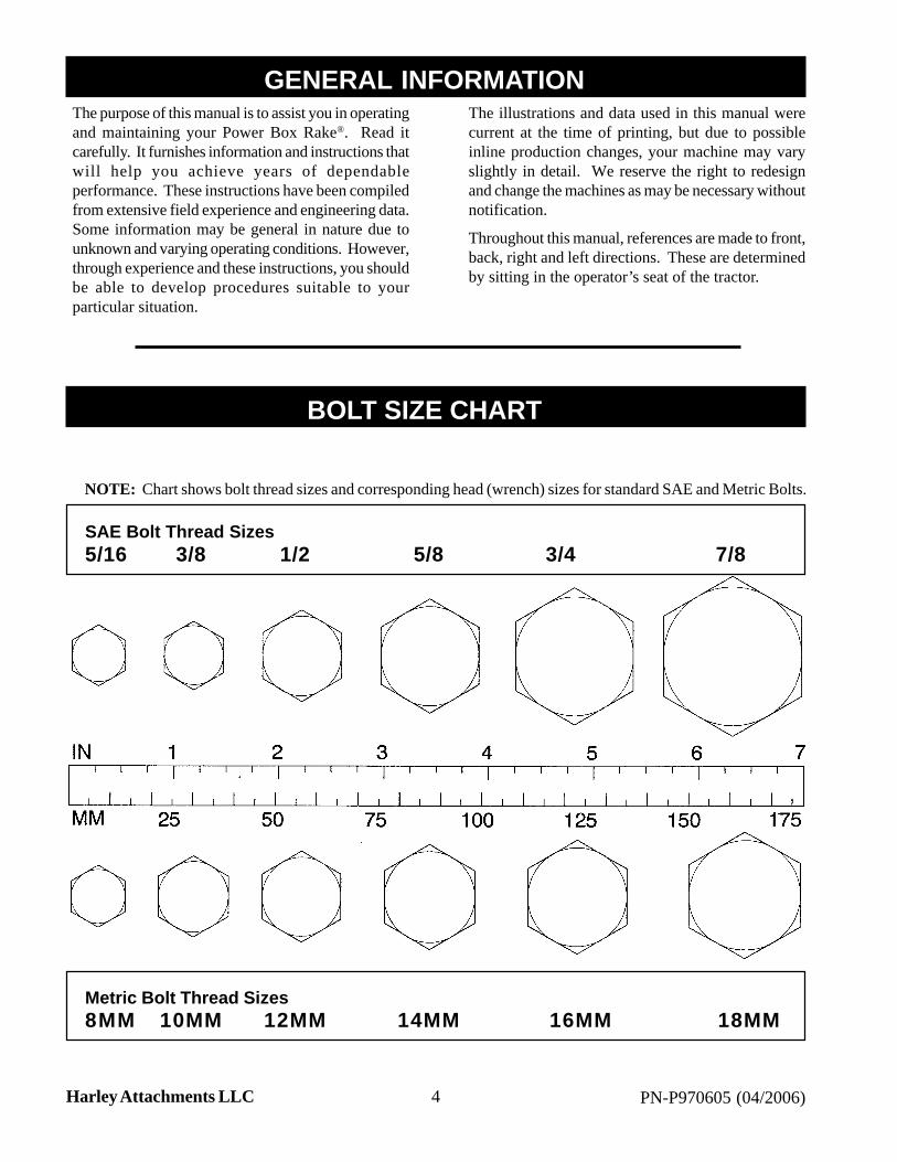
NOTE: Chart shows bolt thread sizes and corresponding head (wrench) sizes for standard SAE and Metric Bolts.
SAE Bolt Thread Sizes5/16 3/8 1/2 5/8 3/4 7/8
Metric Bolt Thread Sizes8MM 10MM 12MM 14MM 16MM 18MM
GENERAL INFORMATION1
BOLT SIZE CHART1

5PN-P970605 (04/2006) Harley Attachments LLC
After every ten (10) hours of operation, check all hardware and tighten where required.
SAE Series Torque ChartDO NOT use these values if a different torque value or tightening procedure is listed for a specific application.Torque values listed are for general use only.
Fasteners should be replaced with the same grade.
Make sure fastener threads are clean and you properly start thread engagement. This will prevent them from failingwhen tightening.
BOLT TORQUE CHART1

6 PN-P970605 (04/2006)Harley Attachments LLC
Metric Series Torque Chart
Use only metric tools on metric hardware. Other tools may not fit properly. They may slip and cause injury.
DO NOT use these values if a different torque value or tightening procedure is listed for a specific application.Torque values listed are for general use only.
Fasteners should be replaced with the same grade.
Make sure fastener threads are clean and you properly start thread engagement. This will prevent them from failingwhen tightening.
After every ten (10) hours of operation, check all hardware and tighten where required.
Safety is a primary concern in the design andmanufacture of our products. Unfortunately, ourefforts to provide safe equipment can be wiped out bya single careless act of an operator.
In addition to the design and configuration ofequipment, hazard control and accident prevention aredependent upon the awareness, concern, prudence, andproper training of personnel involved in the operation,transport, maintenance, and storage of equipment.
It has been said, “The best safety device is an informed,careful operator.” We ask you to be that kind of anoperator.
The designed and tested safety of this equipmentdepends on it being operated within the limitations asexplained in this manual.
TRAINING
• Safety instructions are important! Read allattachment and power unit manuals; follow allsafety rules and safety decal information.(Replacement manuals are available from dealeror, in the United States and Canada, call 1-800-437-9779.) Failure to follow instructions or safetyrules can result in serious injury or death.
• If you do not understand any part of this manualand need assistance, see your dealer.
• Know your controls and how to stop engine andattachment quickly in an emergency.
• Operators must be instructed in and be capable ofthe safe operation of the equipment, itsattachments, and all controls. Do not allow anyoneto operate this equipment without properinstructions.
BOLT TORQUE CHART1
SAFETY RULES1ATTENTION! BECOME ALERT! YOUR SAFETY IS INVOLVED!

7PN-P970605 (04/2006) Harley Attachments LLC
• Keep hands and body away from pressurized lines.Use paper or cardboard, not body parts to checkfor leaks. Wear safety goggles. Hydraulic fluidunder pressure can easily penetrate skin and willcause serious injury or death.
• Make sure that all operating and service personnelknow that in the event hydraulic fluid penetratesskin, it must be surgically removed as soon aspossible by a doctor familiar with this form ofinjury, or gangrene, serious injury, or death willresult. CONTACT A PHYSICIANIMMEDIATELY IF FLUID ENTERS SKINOR EYES. DO NOT DELAY.
• Do not allow children or untrained persons tooperate equipment.
PREPARATION
• Air in hydraulic systems can cause erratic operationand allows loads or equipment components to dropunexpectedly. Before operating or allowinganyone to approach the equipment, purge any airin the system by operating all hydraulic functionsseveral times after connecting equipment,connecting hoses, or doing any hydraulicmaintenance.
• Check that all hardware is tight and properlyinstalled. Always tighten to torque chartspecifications.
• Before starting tractor, check all equipmentdriveline guards for damage and make sure theyrotate freely on all drivelines. Replace anydamaged guards. If guards do not rotate freely ondrivelines, repair and replace bearings beforeoperating.
• Make sure driveline is correct length to preventbottoming out or pulling apart during the full liftrange of the hitch.
• Make sure spring-activated locking pin or collarslides freely and is seated firmly in tractor PTOsplined groove.
• Protective hose sleeves must cover all hoses andbe secured onto metal hose fittings. Replace ifdamaged or if protective sleeve is not properlypositioned or secured.
• After connecting hoses, check that all control leverpositions function as instructed in the Operator’sManual. Do not operate until control lever andequipment movements are correct.
• Make sure all hydraulic hoses, fittings, and valvesare in good condition and not leaking beforestarting power unit or using equipment. Checkand route hoses carefully to prevent damage.Hoses must not be twisted, bent sharply, kinked,frayed, pinched, or come into contact with anymoving parts. Operate moveable componentsthrough full operational range to check clearances.Replace any damaged hoses immediately.
• Always wear relatively tight and belted clothing toavoid entanglement in moving parts. Wear sturdy,rough-soled work shoes and protective equipmentfor eyes, hair, hands, hearing, and head.
• Ensure implement is properly attached, adjusted,and in good operating condition.
• Power unit must be equipped with ROPS or ROPSCAB and seat belt. Keep seat belt securelyfastened. Falling off power unit can result in deathfrom being run over or crushed. Keep foldableROPS systems in “locked up” position at all times.
• Remove accumulated debris from this equipment,tractor, and engine to avoid fire hazard.
• A minimum 20% of tractor and equipment weightmust be on tractor front wheels with attachmentsin “transport” position. Without this weight,tractor could tip over causing personal injury ordeath. The weight may be attained with a loader,front wheel weights, ballast in tires, or front tractorweights. When attaining the minimum 20%weight on the front wheels, you must not exceedthe Roll Over Protection Structure (ROPS) weightcertification. Weigh the tractor and equipment.Do not estimate.
• Ensure all safety decals are installed. Replace ifdamaged. (See “Safety Decals” section forlocation.)
• Ensure shields and guards are properly installedand in good condition. Replace if damaged.
SAFETY RULES1ATTENTION! BECOME ALERT! YOUR SAFETY IS INVOLVED!
8 PN-P970605 (04/2006)Harley Attachments LLC
OPERATIONAL SAFETY
• Consult local utilities before digging. Know locationand depth of, and avoid contacting, all undergroundcables, pipelines, and other hazards in working area.
• Do not allow other people in the area whenoperating, attaching, removing, assembling, orservicing equipment.
• Only engage power when equipment is at groundoperating level. Always disengage power whenequipment is raised off the ground.
• Do not disconnect hydraulic lines until all systempressure is relieved. Lower unit to ground, stopengine, and operate all hydraulic control levers.
• Keep bystanders away from equipment while it isin operation.
• Never go underneath equipment lowered to theground or raised. Never place any part of the bodyunderneath equipment or between moveable partseven when the engine has been turned off.Hydraulic system leak-down, hydraulic systemfailures, mechanical failures, or movement ofcontrol levers can cause equipment to drop or rotateunexpectedly and cause severe injury or death.
• Service work does not require going underneathequipment.
• Read operator’s manual for service instructions orhave done by a qualified dealer.
• Never direct discharge toward people, animals, orproperty.
• Do not operate equipment while under theinfluence of alcohol or drugs.
• Operate only in daylight or good artificial light.
• Keep hands, feet, hair, and clothing away fromequipment while engine is running. Stay clear ofall moving parts.
• Always comply with all state and local lightingand marking requirements.
• No riders are allowed on equipment.
• Always sit in tractor seat when operating controlsor starting engine. Securely fasten seal belt, placetransmission in neutral, engage brake, and ensureall other controls are disengaged before startingtractor engine.
• Operate tractor PTO at RPM speed stated in“Specifications” section.
• Do not operate tractor PTO during transport.
• Stop tractor and implement immediately uponstriking an obstruction. Turn off engine, removekey, inspect, and repair any damage beforeresuming operation.
• Before dismounting tractor or performing anyservice or maintenance, disengage power toimplement, lower the 3-point hitch and all raisedcomponents to the ground, operate valve levers torelease any hydraulic pressure, stop engine, setparking brake, remove key, and unfasten seat belt.
• Lower implement to ground or block securely, turntractor engine off, remove key, and disconnectdriveline from tractor PTO before performing anyservice or maintenance.
• Never go underneath equipment lowered to theground or raised. Never place any part of the bodyunderneath equipment or between moveable partseven when the engine has been turned off.Hydraulic system leak-down, hydraulic systemfailures, mechanical failures, or movement ofcontrol levers can cause equipment to drop or rotateunexpectedly and cause severe injury or death.Service work does not require going underneath.
• Look down and to the rear and make sure area isclear before operating in reverse.
• Use extreme care when working close to fences,ditches, other obstructions, or on hillsides.
• Do no operate on steep slopes.
• Do not stop, start, or change directions suddenlyon slopes.
• Use extreme care and reduce ground speed onslopes and rough terrain.
• Watch for hidden hazards on the terrain duringoperation.
ATTENTION! BECOME ALERT! YOUR SAFETY IS INVOLVED!
SAFETY RULES1

9PN-P970605 (04/2006) Harley Attachments LLC
MAINTENANCE SAFETY
• Your dealer can supply original equipment hydraulicaccessories and repair parts. Substitute parts maynot meet original equipment specifications and maybe dangerous.
• Always wear relatively tight and belted clothing toavoid entanglement in moving parts. Wear sturdy,rough-soled work shoes, and protective equipmentfor eyes, hair, hand, hearing, and head.
• Before dismounting tractor or performing anyservice or maintenance, disengage power toimplement, lower the 3-point hitch and all raisedcomponents to the ground, operate valve levers torelease any hydraulic pressure, stop engine, setparking brake, remove key, and unfasten seat belt.
• Lower implement to ground or block securely, turntractor engine off, remove key, and disconnectdriveline from tractor PTO before performing anyservice or maintenance.
• Do not allow other people in the area whenoperating, attaching, removing, assembling, orservicing equipment.
• Do not modify or alter, or permit anyone else tomodify or alter, the equipment or any of itscomponents in any way.
• Never go underneath equipment lowered to theground or raised. Never place any part of the bodyunderneath equipment or between moveable partseven when the engine has been turned off.Hydraulic system leak-down, hydraulic systemfailures, mechanical failures, or movement ofcontrol levers can cause equipment to drop or rotateunexpectedly and cause severe injury or death.
• Service work does not require going underneathequipment.
• Read operator’s manual for service instructions orhave done by a qualified dealer.
• Ensure implement is properly attached, adjusted,and in good operating condition.
• Never perform service or maintenance with enginerunning.
• Keep all persons away from operator control areawhile performing adjustments, service, ormaintenance.
• Tighten all bolts, nuts, and screws to torque chartspecifications. Check that all cotter pins areinstalled securely to ensure equipment is in a safecondition before operating.
• Ensure all safety decals are installed. Replace ifdamaged. (See “Safety Decals” section forlocation.)
• Ensure shields and guards are properly installedand in good condition. Replace if damaged.
• Do not disconnect hydraulic lines until all systempressure is relieved. Lower unit to ground, stopengine, and operate all hydraulic control levers.
STORAGE
• Follow manual instructions for storage.
• Keep children and bystanders away from storagearea.
ATTENTION! BECOME ALERT! YOUR SAFETY IS INVOLVED!
SAFETY RULES1

10 PN-P970605 (04/2006)Harley Attachments LLC
#4 - PN: P970100
#1 - PN: P970400
#2 - PN: P970300
#5 - PN: P970250
#3 - PN: P970301
ATTENTION! BECOME ALERT! YOUR SAFETY IS INVOLVED!
SAFETY DECALS1REPLACE IMMEDIATELY IF DAMAGED!

11PN-P970605 (04/2006) Harley Attachments LLC
REPLACE IMMEDIATELY IF DAMAGED!
ATTENTION! BECOME ALERT! YOUR SAFETY IS INVOLVED!
SAFETY DECALS1
Figure 1. Safety Decals

12 PN-P970605 (04/2006)Harley Attachments LLC
Safety is a primary concern in the design andmanufacture of our products. Unfortunately, our effortsto provide safe equipment can be wiped out by a singlecareless act of an operator.
In addition to the design and configuration of equipment,hazard control and accident prevention are dependentupon the awareness, concern, prudence, and propertraining of personnel involved in the operation, transport,maintenance, and storage of equipment.
It has been said, “The best safety device is an informed,careful operator.” We ask you to be that kind of anoperator.
The operator is responsible for the safe operation ofthis equipment. Operators must be instructed in andbe capable of the safe operation of the equipment, itsattachments, and all controls. Do not allow anyone tooperate this equipment without proper instructions.
The power rake is designed for removing rock, smalldebris, and for thatching. This manual containsinformation for the T5 model. Refer to the informationin this manual for specifications, parts, assembly, andadjustment.
WARNING
• Safety instructions are important! Read allattachment and power unit manuals; follow allsafety rules and safety decal information.(Replacement manuals are available fromdealer or, in the United States and Canada, call1-800-437-9779.) Failure to follow instructionsor safety rules can result in serious injury ordeath.
• Do not allow children or untrained persons tooperate equipment.
• Power unit must be equipped with ROPS orROPS CAB and seat belt. Keep seat beltsecurely fastened. Falling off power unit canresult in death from being run over or crushed.Keep foldable ROPS systems in “locked up”position at all times.
• Do not allow other people in the area whenoperating, attaching, removing, assembling, orservicing equipment.
• Never go underneath equipment lowered tothe ground or raised. Never place any part of
the body underneath equipment or betweenmoveable parts even when the engine hasbeen turned off. Hydraulic system leak-down,hydraulic system failures, mechanical failures,or movement of control levers can causeequipment to drop or rotate unexpectedly andcause severe injury or death.
• Service work does not require goingunderneath equipment.
• Read Operator’s Manual for serviceinstructions or have done by a qualifieddealer.
• Before dismounting tractor or performing anyservice or maintenance, disengage power toimplement, lower the 3-point hitch and allraised components to the ground, operate valvelevers to release any hydraulic pressure, stopengine, set parking brake, remove key, andunfasten seat belt.
• Ensure implement is properly attached,adjusted, and in good operating condition.
ATTACHING POWER RAKE TO TRACTOR
Move tractor into position in front of the power rake.Move back slowly and carefully, not allowing anyoneto be between the tractor and the rake. Turn off tractorengine. Attach the two lower arms of the 3-point hitchwith the two hitch-pin assemblies.
Attach the tractor center link to the upper hitch pointof the power rake. Use either the “lock-out” setting orthe “float” feature depending on your application.
Attach the front PTO from the power rake to the tractor.Slide the front section of the PTO into the back sectionand attach to the PTO shaft at the rear of the tractor.
Wrap driveline storage chain around hitch tube andsecure it so that it will not contact PTO driveline.
OPERATION1

13PN-P970605 (04/2006) Harley Attachments LLC
IMPORTANT
• If the PTO is too long, severe PTO andgearbox damage is possible when hookingup the PTO from the power rake to thetractor. The front PTO is long enough to fit avariety of tractors. It is possible that the frontPTO will need to be cut. There will be NObenefit by cutting only one telescopingsection. Both sections of the PTO must becut. DO NOT FORCE THE PTO TO FIT.
• WARRANTY IS VOID IF THE PTO ISTOO LONG, resulting in gearbox, PTO, yoke,or cross bearing damage.
The PTO, when attached to the tractor and gearbox,must not extend so there is less than five inches ofoverlap within the PTO.
Attach the two hydraulic lines on the rake to the twofemale hydraulic couplers on the tractor. The hydraulichose ends on the power rake are ISO male couplers,which are compatible with newer tractors.
Raise jackstand and secure in operating position.
IMPORTANT
• Always clean connector ends prior toattaching. Dirt could contaminate hydraulicfluid and damage the hydraulic system.
POWER RAKE FUNCTION
The tractor PTO drives the roller, which digs into theground, cultivating and pulling up rocks, roots, anddebris.
The clean soil goes between the roller and barrier,while the rocks, roots, and debris work to the side in awindrow.
With the end plates mounted in the working positionand the rake straight (end plates parallel with tractortires), material can be moved along, filling in the lowspots.
Maximum safe PTO operating speed is 540 RPM.
PRE-OPERATION CHECK LIST
___ Review and follow all safety rules and safetydecal instructions on pages 6 through 11.
___ Check that all safety decals are installed and ingood condition. Replace if damaged.
___ Check that all shields and guards are properlyinstalled and in good condition. Replace ifdamaged.
___ Check that all hardware and cotter pins areproperly installed and secured.
___ Check that equipment is properly and securelyattached to tractor.
___ Make sure driveline spring-activated locking pinor collar slides freely and is seated firmly intractor PTO spline groove.
___ Before starting tractor, check all equipmentdriving guards for damage and make sure theyrotate freely on all drivelines. Replace anydamaged guards. If guards do not rotate freelyon drivelines, repair and replace bearings beforeoperating.
___ Do not allow riders.
___ Check for and keep all bystanders away fromequipment working area.
___ Make sure gearbox is filled to the correct levelwith high quality 80W-90 gear oil.
___ Check all lubrication points and grease asinstructed in “Maintenance, Lubrication”information.
___ Check that all hydraulic hoses and fittings arein good condition and not leaking before startingskid steer. Check that hoses are not twisted,bent sharply, kinked, frayed, or pulled tight.Replace any damaged hoses immediately.
___ Make sure tractor ROPS or ROPS CAB and seatbelt are in good condition. Keep seat beltsecurely fastened during operation.
___ Check tire pressure and service if necessary.
OPERATION1

14 PN-P970605 (04/2006)Harley Attachments LLC
right for placing material in a windrow.
With the power rake angle cylinder connected to atractor hydraulic control valve, move tractor controlvalve to select the desired angle. Return the tractorcontrol to neutral to maintain the selected angle.
Power Roller
The roller should be level with the ground. To level therake from side to side, adjust one of the tractor 3-pointlower lift arms.
The power rake should be level front to back. Levelthe rake using the tractor 3-point top link, the 3-pointlift arms, or the gauge wheels.
To allow the roller to penetrate deeper into the ground,loosen the handle and raise the gauge wheels. Toachieve the opposite, lower the gauge wheels.
Be sure to check the air pressure in each tire regularlyso that an even, consistent grade will be maintained.
Barrier
The normal gap between the roller and barrier foraverage conditions is about 1-1/4". This gap can beadjusted by rotating the barrier and pinning in desiredposition. A wider opening will allow more dirt and rockto pass through, allowing wet soil to dry for final raking.For finer raking, reduce the gap. (Be careful not to letroller hit barrier.) The gap should be the same all theway across. Barrier adjustment is shown in Figure 2.
Operating Depth
When power raking, the depth will determine how muchdirt is carried ahead of the roller. The ideal depth willvary with conditions and can be anywhere fromskimming the surface to about 3" deep. Seeinstructions in “Power Roller” above to set roller depth.
When making the first windrow, the level of dirt maybe halfway up on the barrier. When moving thewindrow two or three times, the level of the dirt maybe to the top of the barrier. However, try to preventmaterial from flowing over the top.
The power rake allows fast raking of large areas ofground by being able to make windrows several times.Of course, the volume or density of the material beingraked will dictate how many times a windrow can bemoved.
OPERATING INSTRUCTIONS
Read and understand the power rake and tractoroperator’s manuals before operating the power rake.Failure to do so may result in death, serious personalinjury, or property damage.
Never raise the power rake more than a few inches offthe ground when traveling from job site to job site.
Shut off the engine, set brake, remove key, and removeseat belt. Dismount the tractor.
WARNING
• Look down and to the rear and make surearea is clear before operating in reverse.
• Never direct discharge toward people,animals, or property.
• Only engage power when equipment is atground operating level. Always disengagepower when equipment is raised off the ground.
Start-Up Sequence
WARNING
• Only engage power when equipment is atground operating level. Always disengagepower when equipment is raised off theground.
Before using your new Harley Power Box Rake, theslip clutch assembly must be in RUN-IN. SeeCLUTCH in the maintenance section, page 21, forthe RUN-IN procedure. After you have completedthe RUN-IN of the clutch, return to the operatinginstructions and proceed with start-up. Failure to runthe clutch in could result in pre-mature drive linefailure and warranty will be voided.
Start tractor engine.
Lower power rake slowly to the ground.
Engage tractor PTO.
Increase engine rpm to give desired rpm at the roller.Normal operating speed must not exceed 540 rpm. Ifoperating in heavy rock, reduce the speed slightly.
Move the tractor forward. Select a slow tractor speedand increase slightly until operation is satisfactory.
Ground Speed
Ground speed should be between 3 mph and 5 mphunder normal conditions. In heavy rock, reduce theground speed to 1 mph to 3 mph.
OPERATION1Power Rake Angle Adjustment
The power rake may be angled up to 15 degrees left or
15PN-P970605 (04/2006) Harley Attachments LLC
Soil can be removed from the windrow of rocks bymoving it back and forth a few times onto the cleanarea. If dirt clods are a problem, running the tractortire over the windrow and then moving it a final timewill help to break up and cut down on dirt clods.
End Plates
The function of the end plates is to contain the materialin front of the roller while the clean material passesbetween the roller and barrier.
With the end plates mounted in the operating positionand the rake straight (end plates parallel with tractortires), material can be moved along, filling in the lowspots.
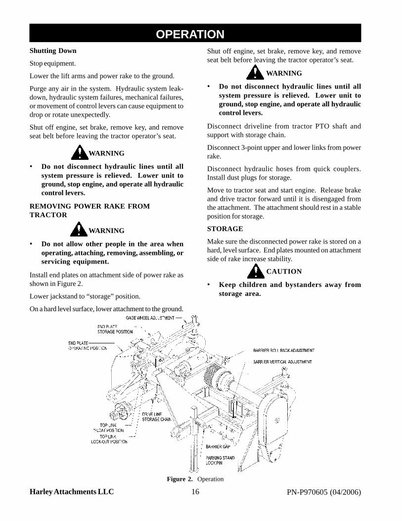
By decreasing the gap between the roller and barrier,more material can be pulled along. Barrier adjustmentis shown in Figure 2.
When not using the end plates for operation, they canbe placed in “storage” position, see Figure 2.
Make sure the disconnected power rake is stored ona hard, level surface. Use the end plates mounted onattachment side of rake to ensure stability.
Operator Production
Successful operation of the power rake will come withoperator experience. The rake’s performance alsodepends on the type and size of the tractor it’s mountedon.
An operator that masters the technique of adjustingthe angle of attack of the roller against the soil willalso find ideal settings under various conditions to givethe desired results.
IMPORTANT
• Do not drop power rake to the ground withthe roller turning. Sudden high-speed joltsmultiply stress to the driveline and can causeextreme damage.
Application Techniques
The power rake is capable of many applications. Thefollowing are some of the common applications.
See Figure 2 for adjustment locations.
Pulverizing Topsoil
For breaking up compacted soil or conditioning hardenedbaseball diamonds, the 3-point top link is set in the “lock-out” position so that down pressure can be exerted onthe tooth roller. The top link is shortened to take theguide wheels off the ground so only the toothed rolleris in contact with the ground. Maintain sufficient rpmto avoid stalling the toothed roller in its progress. Therake can be straight or angled, with the barrier openedup to allow material to flow over the roller.
Debris Removal
Once the surface has been loosened, the process ofremoving debris can begin. The 3-point hitch top linkis mounted in the “float” position holes. This allowsthe rake to begin the early stages of the final gradingprocess. The 3-point hitch is lowered until the guidewheels control the depth of the toothed roller. Therake can be angled at this time for windrowing debrisor the rake can be set straight with both end platesinstalled to collect debris. Tractor travel speed shouldbe increased for this process.
Finish Grading
For this operation, set the tractor toplink in the “float”position and mount both end plates in the “forward”position. The rake is tilted forward until the teeth ofthe toothed roller are barely touching the soil. Tractorspeed can be increased for this operation, the idea beingto collect material from the high spots and leave it inthe low areas.
Spreading Fill and Topsoil
Start with tractor toplink in “fixed” position and raketiled on gauge wheels, since depth of cut is not theobjective. End plates can be installed and the windrowangle set as needed to control the material movement.
Changing Grade
Grade modification can be accomplished during finishgrading by angling the rake to collect and windrow themaximum amount of material toward targeted areas.
Thatching Existing Grass Areas
This procedure is done with the 3-point toplink in the“lock-out” position so accurate depth control can bemaintained. The attachment plate should be lengthenedto support the rake on the gauge wheels and toothedroller raised so teeth are just grazing the surface. Selectand maintain a slow travel speed.
OPERATION1
16 PN-P970605 (04/2006)Harley Attachments LLC
Shutting Down
Stop equipment.
Lower the lift arms and power rake to the ground.
Purge any air in the system. Hydraulic system leak-down, hydraulic system failures, mechanical failures,or movement of control levers can cause equipment todrop or rotate unexpectedly.
Shut off engine, set brake, remove key, and removeseat belt before leaving the tractor operator’s seat.
WARNING
• Do not disconnect hydraulic lines until allsystem pressure is relieved. Lower unit toground, stop engine, and operate all hydrauliccontrol levers.
REMOVING POWER RAKE FROMTRACTOR
WARNING
• Do not allow other people in the area whenoperating, attaching, removing, assembling, orservicing equipment.
Install end plates on attachment side of power rake asshown in Figure 2.
Lower jackstand to “storage” position.
On a hard level surface, lower attachment to the ground.
Shut off engine, set brake, remove key, and removeseat belt before leaving the tractor operator’s seat.
WARNING
• Do not disconnect hydraulic lines until allsystem pressure is relieved. Lower unit toground, stop engine, and operate all hydrauliccontrol levers.
Disconnect driveline from tractor PTO shaft andsupport with storage chain.
Disconnect 3-point upper and lower links from powerrake.
Disconnect hydraulic hoses from quick couplers.Install dust plugs for storage.
Move to tractor seat and start engine. Release brakeand drive tractor forward until it is disengaged fromthe attachment. The attachment should rest in a stableposition for storage.
STORAGE
Make sure the disconnected power rake is stored on ahard, level surface. End plates mounted on attachmentside of rake increase stability.
CAUTION
• Keep children and bystanders away fromstorage area.
Figure 2. Operation
OPERATION1
17PN-P970605 (04/2006) Harley Attachments LLC
The information in this section is written for operatorswho possess basic mechanical skills. Should you needhelp, your dealer has trained service techniciansavailable. For your protection, read and follow allsafety information in this manual.
Regular preventive maintenance and immediate repairof broken or worn parts will ensure maximumefficiency and long life.
Because of the nature of the jobs the power rake does,such as site preparation and rock raking, the powerrake is constantly vibrating and shaking. Parts mayloosen up as it is used. One of the most importantfunctions an operator can perform is observing andinspecting the equipment for loose or worn parts toprevent further damage or excessive downtime.
WARNING
• Never go underneath equipment lowered tothe ground or raised. Never place any part ofthe body underneath equipment or betweenmoveable parts even when the engine has beenturned off. Hydraulic system leak-down,hydraulic system failures, mechanical failures,or movement of control levers can causeequipment to drop or rotate unexpectedly andcause severe injury or death.
• Service work does not require goingunderneath equipment.
• Read operator’s manual for serviceinstructions or have done by a qualifieddealer.
• Before dismounting tractor or performing anyservice or maintenance, disengage power toimplement, lower the 3-point hitch and allraised components to the ground, operate valvelevers to release any hydraulic pressure, stopengine, set parking brake, remove key, andunfasten seat belt.
• Do not allow other people in the area whenoperating, attaching, removing, assembling, orservicing equipment.
• Never perform service or maintenance withengine running.
• Ensure shields and guards are properlyinstalled and in good condition. Replace ifdamaged.
• Keep hands and body away from pressurizedlines. Use paper or cardboard, not body partsto check for leaks. Wear safety goggles.Hydraulic fluid under pressure can easilypenetrate skin and will cause serious injury ordeath.
WARNING
• Make sure that all operating and servicepersonnel know that in the event hydraulic fluidpenetrates skin, it must be surgically removedas soon as possible by a doctor familiar withthis form of injury, or gangrene, serious injury,or death will result. CONTACT APHYSICIAN IMMEDIATELY IF FLUIDENTERS SKIN OR EYES. DO NOT DELAY.
• Make sure all hydraulic hoses, fittings, andvalves are in good condition and not leakingbefore starting power unit or using equipment.Check and route hoses carefully to preventdamage. Hoses must not be twisted, bentsharply, kinked, frayed, pinched, or come intocontact with any moving parts. Operatemoveable components through full operationalrange to check clearances. Replace anydamaged hoses immediately.
CAUTION
• Your dealer can supply original equipmenthydraulic accessories and repair parts.Substitute parts may not meet originalequipment specifications and may bedangerous.
• Always wear relatively tight and beltedclothing to avoid entanglement in movingparts. Wear sturdy, rough-soled work shoes,and protective equipment for eyes, hair, hand,hearing, and head.
WARNING
• Do not modify or alter, or permit anyone elseto modify or alter, the equipment or any of itscomponents in any way.
• Ensure all safety decals are installed. Replaceif damaged. (See “Safety Decals” section forlocation.)
MAINTENANCE1

18 PN-P970605 (04/2006)Harley Attachments LLC
DAILY MAINTENANCE
When operating the power rake, check the tractorhydraulic system to be sure the level of hydraulic oilis adequate. If necessary, add hydraulic oil asrecommended in your tractor operator’s manual.
Repair hydraulic oil leaks promptly to avoid loss ofoil and serious personal injury from escaping oil.
After every 10 hours of operation, check all hardwareand tighten where required.
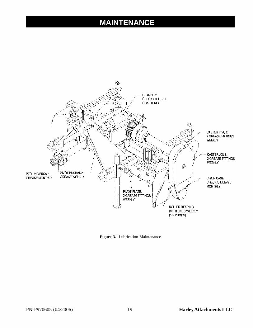
Check oil level in chain case.
WEEKLY MAINTENANCE
Lubricate all pivot points. Lightly lubricate bearing ateach end of roller (1 - 2 pumps). Use a lithium greaseof #2 consistency with a MOLY (molybdenumdisulfide) additive for all locations. Be sure to cleanfittings thoroughly before attaching grease gun. SeeFigure 3.
Inspect drive chain.
Check tire pressure. Maintain 20 psi cold.
Lubricate driveline universal joints.
MONTHLY MAINTENANCE
Inspect and clean safety decals. Replace if damaged.(See “Safety Decals” section for location.)
Check gearbox oil level.
QUARTERLY MAINTENANCE
Change oil in chain case and add 1.5 pints of #00 fuildgear grease.
PRELIMINARY CHECK
The best maintenance is regular preventive checks,particularly when the machine is new. Check that allnuts and bolts are tight.
CHAIN MAINTENANCE
The drive chain should be inspected weekly. New chainhas a tendency to stretch, so it is necessary to checkthe chain tension to prevent flopping around, thuscausing potential problems.
Chain tension is preset with the extension spring. Ifthe chain becomes excessively loose, it may benecessary to remove one link (two pitches). If unableto reassemble, add an offset link to lengthen the chain.
IMPORTANT
• Replacement chain should be only highquality original equipment chain for longer life.
When being stored for a long period or at end of season,change the oil, adding #00 fluid gear grease, and rotatethe roller several times allowing the chain to be coatedwith oil, enhancing chain life. Rotate the rollerperiodically to maintain lubrication. In order to rotatethe roller and chain, you must hook the two hydraulichoses together.
SPROCKETS
Sprockets should be checked to be sure slotted hex nutor hex bolt is tight, the cotter pin is in place, and thesprocket cannot move on shaft.
PTO DRIVE LINES
Periodically check the yoke on both ends of the frontPTO to the tractor. Make sure the set screws/jam nutsare tight and the yoke is not moving on the shaft. PTOshafts and U-joints should be sparingly lubricatedweekly.
GEARBOX
The gearbox is almost maintenance-free, but shouldbe checked monthly to be sure that the oil level ismaintained at half full. EP 80-90 wt. gear lube is rec-ommended for use in the gearbox. Oil should bechanged after the first 100 hours or 30 days of operat-ing. Then, normal change intervals of 1,000 hours or12 months of operation should be adequate. In thecase of seasonal usage, it is best to change the oil atthe end of the season to remove moisture and corro-sive contaminants.
It should be noted that the gearbox only exceeds itsthermal capacity when the oil temperature exceeds200°F.
CLUTCH
See “Run-In” procedure on pages 21 & 22.
MAINTENANCE1
19PN-P970605 (04/2006) Harley Attachments LLC
Figure 3. Lubrication Maintenance
MAINTENANCE1
20 PN-P970605 (04/2006)Harley Attachments LLC
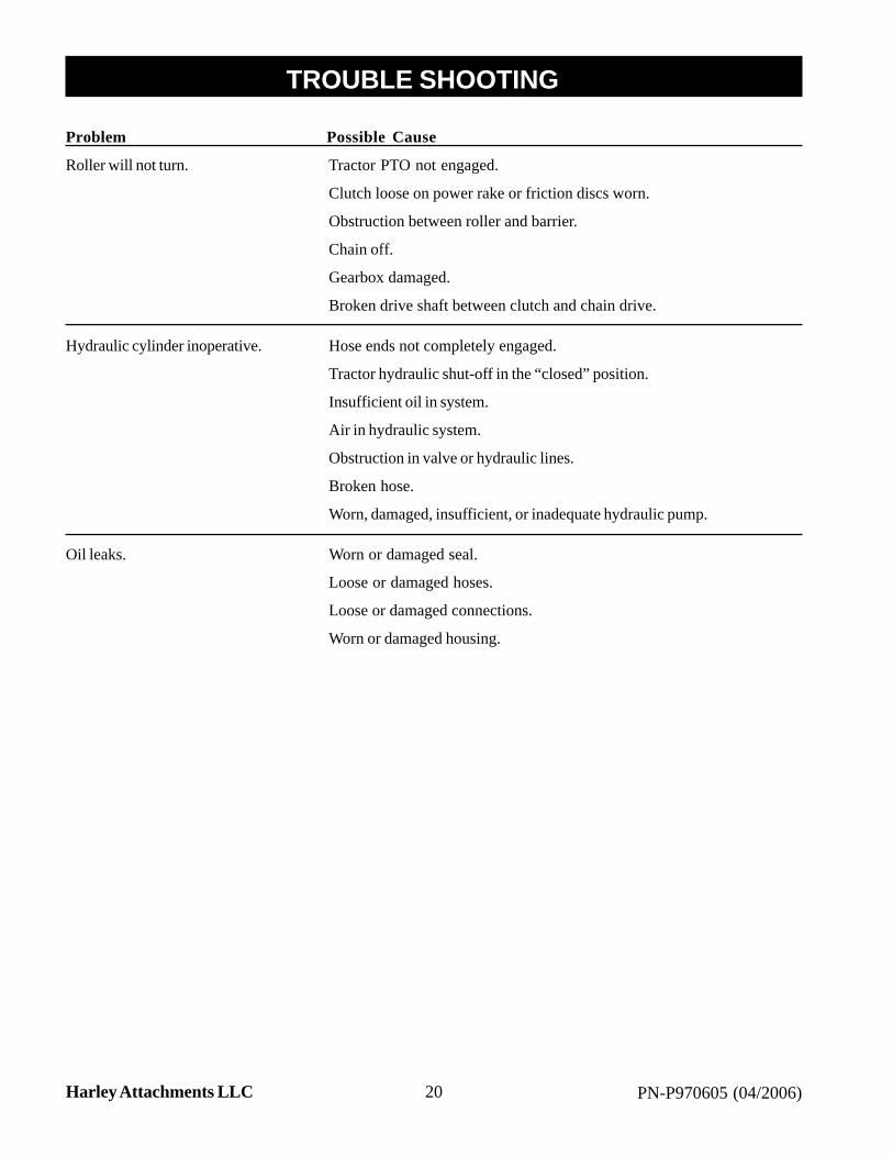
Problem Possible Cause
Roller will not turn. Tractor PTO not engaged.
Clutch loose on power rake or friction discs worn.
Obstruction between roller and barrier.
Chain off.
Gearbox damaged.
Broken drive shaft between clutch and chain drive.
Hydraulic cylinder inoperative. Hose ends not completely engaged.
Tractor hydraulic shut-off in the “closed” position.
Insufficient oil in system.
Air in hydraulic system.
Obstruction in valve or hydraulic lines.
Broken hose.
Worn, damaged, insufficient, or inadequate hydraulic pump.
Oil leaks. Worn or damaged seal.
Loose or damaged hoses.
Loose or damaged connections.
Worn or damaged housing.
TROUBLE SHOOTING1

21PN-P970605 (04/2006) Harley Attachments LLC
The information in this section is written for dealerservice personnel. The repair described herein requiresspecial skills and tools. If your shop is not properlyequipped or your mechanics are not properly trained inthis type of repair, you may be time and money aheadto replace complete assemblies.
WARNING
• Never go underneath equipment lowered tothe ground or raised. Never place any part ofthe body underneath equipment or betweenmoveable parts even when the engine hasbeen turned off. Hydraulic system leak-down,hydraulic system failures, mechanical failures,or movement of control levers can causeequipment to drop or rotate unexpectedly andcause severe injury or death.
• Service work does not require goingunderneath equipment.
• Read Operator’s Manual for serviceinstructions or have done by a qualified dealer.
CAUTION
• Always wear relatively tight and beltedclothing to avoid entanglement in movingparts. Wear sturdy, rough-soled work shoesand protective equipment for eyes, hair, hands,hearing, and head.
• Do not allow other people in the area whenoperating, attaching, removing, assembling, orservicing equipment.
• Do not modify or alter, or permit anyone elseto modify or alter, the equipment or any of itscomponents in any way.
• Do not disconnect hydraulic lines until allsystem pressure is relieved. Lower unit toground, stop engine, and operate all hydrauliccontrol levers.
• Ensure implement is properly attached,adjusted, and in good operating condition.
• Ensure all safety decals are installed. Replaceif damaged. (See “Safety Decals” section forlocation.)
• Ensure shields and guards are properlyinstalled and in good condition. Replace ifdamaged.
MAINTENANCE1CLUTCH
Run-In
If the rake has not been used or has not been operatedfor one year, the following run-in procedure isrecommended.
WARNING
• Before dismounting tractor or performing anyservice or maintenance, disengage power tothe implement, lower the 3-point hitch and allraised components to the ground, operatevalve levers to release any hydraulicpressure, stop engine, set parking break,remove key, and unfasten safety belt.
The Weasler Torqmaster clutch is a pre-set, non-adjustable friction disc clutch. Follow the directionsbelow for run-in and clutch maintenance. See Figures4 & 9, pages 22 & 34 for Parts Identification.
PROCEDURE:
1. Make sure the tractor is off and the PTO isdisengaged.
2. Disconnect the drive line from the tractor.
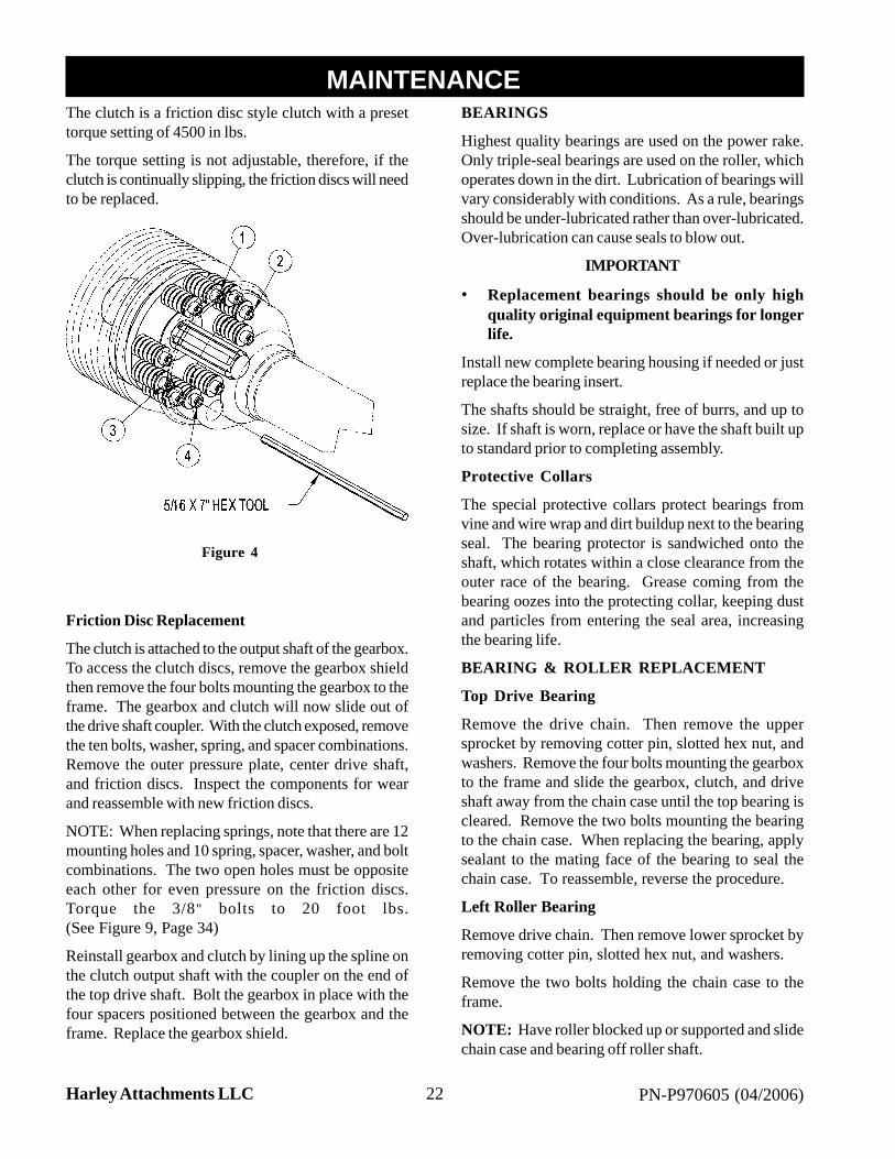
3. Insert the hex tool through hole in PTO shield andloosen four (4) of the ten (10) bolts holding springpressure on clutch discs. (As indicated on diagram.)
4. Attach the drive line to the tractor and start the tractor.Engage the tractor PTO and run the rake for a fewseconds or until the friction clutch visibly smokes..
5. Disengage the tractor PTO and shut the tractor off.
6. Disconnect the drive line from the tractor.
7. Retighten the four (4) bolts that were loosened forthis procedure.
22 PN-P970605 (04/2006)Harley Attachments LLC
The clutch is a friction disc style clutch with a presettorque setting of 4500 in lbs.
The torque setting is not adjustable, therefore, if theclutch is continually slipping, the friction discs will needto be replaced.
Friction Disc Replacement
The clutch is attached to the output shaft of the gearbox.To access the clutch discs, remove the gearbox shieldthen remove the four bolts mounting the gearbox to theframe. The gearbox and clutch will now slide out ofthe drive shaft coupler. With the clutch exposed, removethe ten bolts, washer, spring, and spacer combinations.Remove the outer pressure plate, center drive shaft,and friction discs. Inspect the components for wearand reassemble with new friction discs.
NOTE: When replacing springs, note that there are 12mounting holes and 10 spring, spacer, washer, and boltcombinations. The two open holes must be oppositeeach other for even pressure on the friction discs.Torque the 3/8" bolts to 20 foot lbs.(See Figure 9, Page 34)
Reinstall gearbox and clutch by lining up the spline onthe clutch output shaft with the coupler on the end ofthe top drive shaft. Bolt the gearbox in place with thefour spacers positioned between the gearbox and theframe. Replace the gearbox shield.
BEARINGS
Highest quality bearings are used on the power rake.Only triple-seal bearings are used on the roller, whichoperates down in the dirt. Lubrication of bearings willvary considerably with conditions. As a rule, bearingsshould be under-lubricated rather than over-lubricated.Over-lubrication can cause seals to blow out.
IMPORTANT
• Replacement bearings should be only highquality original equipment bearings for longerlife.
Install new complete bearing housing if needed or justreplace the bearing insert.
The shafts should be straight, free of burrs, and up tosize. If shaft is worn, replace or have the shaft built upto standard prior to completing assembly.
Protective Collars
The special protective collars protect bearings fromvine and wire wrap and dirt buildup next to the bearingseal. The bearing protector is sandwiched onto theshaft, which rotates within a close clearance from theouter race of the bearing. Grease coming from thebearing oozes into the protecting collar, keeping dustand particles from entering the seal area, increasingthe bearing life.
BEARING & ROLLER REPLACEMENT
Top Drive Bearing
Remove the drive chain. Then remove the uppersprocket by removing cotter pin, slotted hex nut, andwashers. Remove the four bolts mounting the gearboxto the frame and slide the gearbox, clutch, and driveshaft away from the chain case until the top bearing iscleared. Remove the two bolts mounting the bearingto the chain case. When replacing the bearing, applysealant to the mating face of the bearing to seal thechain case. To reassemble, reverse the procedure.
Left Roller Bearing
Remove drive chain. Then remove lower sprocket byremoving cotter pin, slotted hex nut, and washers.
Remove the two bolts holding the chain case to theframe.
NOTE: Have roller blocked up or supported and slidechain case and bearing off roller shaft.
MAINTENANCE1
Figure 4
23PN-P970605 (04/2006) Harley Attachments LLC
MAINTENANCE1NOTE: The top drive shaft will come off with thechain case.
Loosen bolt on the bearing tube that holds cartridgebearing in place. Remove bearing and O-ring.
To replace, reverse the procedure. Be sure all partsand wear surfaces are thoroughly clean and in goodcondition. Be sure O-ring is also in good condition.
When replacing bearing, first put O-ring on bearing.Apply a coat of grease on O-ring. Slide bearing in andapply moderate pressure on bearing so O-ring will seatand spread slightly, thus keeping the oil in chain casefrom escaping through the bearing.
Right Roller Bearing
Remove the hex bolt and bearing cap from outside ofbearing.
Loosen bolt on the bearing tube that holds cartridgebearing in place. Pry bearing tube apart to free bearingassembly.
NOTE: Have roller blocked up or supported. Prybearing off of shaft and out of bearing holder.
To replace, reverse the procedure. Be sure all partsand wear surfaces are thoroughly clean and in goodcondition.
Roller Replacement
It will be necessary to have a lifting device or additionalhelp while removing and replacing the roller. The rollerweighs approximately 100 lbs.
Remove upper and lower chain case covers.
Remove tension spring and drive chain. Then removelower sprocket by removing cotter pin, slotted nut, andwashers. Remove the sleeve behind the sprocket youjust removed.
NOTE: Have the roller blocked up or supported.
Remove the two bolts holding chain case to frame andslide chain case off of roller shaft. The roller bearingwill stay in the chain case.
NOTE: If chain case bearing is also being replaced,see “Left Roller Bearing” page 22.
Loosen the bolt on the bearing tube of the non-driveend, sliding roller and bearing out of frame.
Remove hex bolt, bearing cap, bearing, and protectivecollar from roller. On roller to be installed, place machinebushing and protective collar against end plate of roller.Place bearing and bearing cap on roller. Clamp in placewith hex bolt and lock washer into end of roller shaft.
Slide roller and bearing into bearing tube on non-driveend of frame. Do not tighten bearing tube at this time.
Place spacer, protective collar, and O-ring from splinedend of removed roller onto replacement roller. CheckO-ring for cuts or nicks. Apply sealant to bearing areaof shaft. Slide chain case back onto roller and bolt toframe.
Replace sleeve, sprocket, and washers on drive shaft.Clamp solid with the 3/4" slotted nut. Check that rollerclears frame on both ends. Adjust, if required.
Tighten 3/8" bolt in bearing tube on non-drive end offrame.

24 PN-P970605 (04/2006)Harley Attachments LLC
• Always wear relatively tight and beltedclothing to avoid entanglement in movingparts. Wear sturdy, rough-soled work shoesand protective equipment for eyes, hair, hands,hearing, and head.
WARNING
• Keep hands and body away from pressurizedlines. Use paper or cardboard, not body partsto check for leaks. Wear safety goggles.Hydraulic fluid under pressure can easilypenetrate skin and will cause serious injury ordeath.
• Make sure that all operating and servicepersonnel know that in the event hydraulicfluid penetrates skin, it must be surgicallyremoved as soon as possible by a doctorfamiliar with this form of injury, or gangrene,serious injury, or death will result.CONTACT A PHYSICIAN IMMEDIATELYIF FLUID ENTERS SKIN OR EYES. DONOT DELAY.
• Route hydraulic hoses carefully to preventdamage. Hoses must not be twisted, bentsharply, kinked, frayed, pinched, or come intocontact with any moving parts. Operatemoveable components through full operationalrange to check clearances. Replace anydamaged hoses immediately.
• Do not allow other people in the area whenoperating, attaching, removing, assembling, orservicing equipment.
• Do not modify or alter, or permit anyone elseto modify or alter, the equipment or any of itscomponents in any way.
SET-UP INSTRUCTIONS
The power rake is shipped partially assembled.Assembly will be easier if components are aligned andloosely assembled before tightening hardware.Recommended torque values for hardware are locatedon pages 5 and 6.
Select a suitable working area. Refer to illustrations,accompanying test, parts lists, and exploded viewdrawings.
Tools Required
9/16" Wrench
Jackstands
It is advisable to have a mechanical lifting device tofacilitate uncrating.
Unpacking Crate
Be careful of nails in boards when uncrating.
Remove top, sides, and ends of crate.
Remove end plates.
Remove gauge wheel assemblies.
Remove parts box.
Remove power rake from crate. Remove loose nailsfrom boards and dispose of crate according to localcodes.
ASSEMBLY PROCEDURE
WARNING
• Do not allow other people in the area whenoperating, attaching, removing, assembling,or servicing equipment.
For reference, front, back, left, and right directions aredetermined by sitting in the tractor operator’s seat.
Do not permit any bystanders within 10 feet of powerrake during assembly.
Set roller frame upright and securely block in positionwith jackstands (not supplied).
IMPORTANT
• Do not add front PTO half to power rake yet.Follow instructions and important noticeconcerning the front PTO in the “Attachingand Detaching Power Rake” section.
Slide the parking stand into the receiving tube and pinin place.
Attach the two (2) gauge wheel assemblies to the mainframe with two (2) 3/8" U-bolts and lock nuts. Referto Figure 5 for specific location of gauge assembly.
Mount the left and right end plates to the frame. Notethe storage location for future reference.
Position barrier adjustment bar into position and placepin through hole.
CAUTION
ASSEMBLY1

25PN-P970605 (04/2006) Harley Attachments LLC
ASSEMBLY1--IMPORTANT NOTICE--
Do NOT add front PTO half to Power Box Rake® yet.Follow instructions and important notice concerning thefront PTO in the Attaching and Detaching Power BoxRake® section.
5. Reattach the gearbox shield over gearbox using two1/2" x 2" hex bolts and lock washers.
6. Remove the 1" x 2-5/8" bolt from the main frame.Pivot the mast frame to align hole in rod end of cylinderover square nut welded to the main frame. Apply Loc-Tite to threads of 1" x 2-5/8" bolt and attach rod end ofhydraulic cylinder.
7. Attach the two gauge wheel assemblies to the mainframe with two 1/2" U-bolts, lock washers, and nuts.
8. Mount the left and right endplates to the frame.
9. Check the gear lube level in the chain case. Add#00 fuild gear grease, if required.
This should complete the assembly of your new PowerBox Rake®. Make sure that all guards/shields are inplace and are not removed during use.
WARNING
• Make sure all hydraulic hoses, fittings, andvalves are in good condition and not leakingbefore starting power unit or using equipment.Check and route hoses carefully to preventdamage. Hoses must not be twisted, bentsharply, kinked, frayed, pinched, or come intocontact with any moving parts. Operatemoveable components through fulloperational range to check clearances.Replace any damaged hoses immediately.

26 PN-P970605 (04/2006)Harley Attachments LLC
NOTES1
27PN-P970605 (04/2006) Harley Attachments LLC
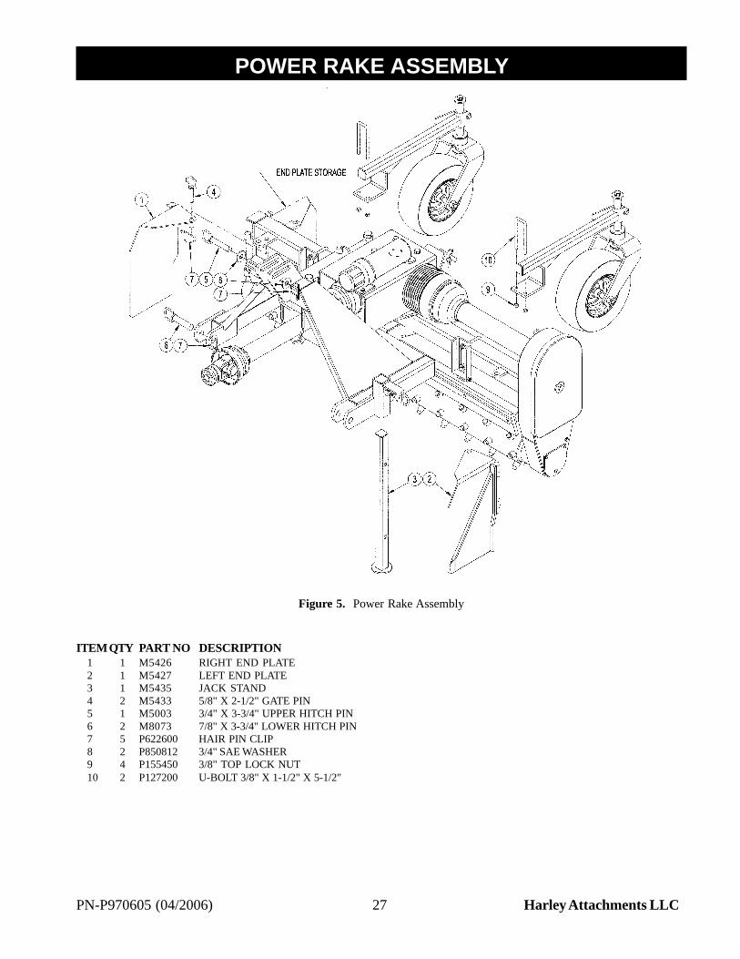
ITEMQTY PART NO DESCRIPTION1 1 M5426 RIGHT END PLATE2 1 M5427 LEFT END PLATE3 1 M5435 JACK STAND4 2 M5433 5/8" X 2-1/2" GATE PIN5 1 M5003 3/4" X 3-3/4" UPPER HITCH PIN6 2 M8073 7/8" X 3-3/4" LOWER HITCH PIN7 5 P622600 HAIR PIN CLIP8 2 P850812 3/4" SAE WASHER9 4 P155450 3/8" TOP LOCK NUT10 2 P127200 U-BOLT 3/8" X 1-1/2" X 5-1/2"
POWER RAKE ASSEMBLY1
Figure 5. Power Rake Assembly

28 PN-P970605 (04/2006)Harley Attachments LLC
ROLLER FRAME ASSEMBLY1
Figure 6. Roller Frame Assembly

29PN-P970605 (04/2006) Harley Attachments LLC
ROLLER FRAME ASSEMBLY PARTS LIST1ITEM QTY PART NO DESCRIPTION
1 1 M5495 MAIN FRAME2 1 M5474 CARBIDE TOOTH ROLLER3 1 M4410 CHAIN CASE4 2 M20192 1-3/8" BEARING COLLAR5 1 P015310 1-3/8" BEARING CAP6 4 M5463 BEARING SPACER7 1 M5440 DRIVE BEARING ASSEMBLY
P015209 1-3/8" CYLINDRICAL BEARING HOUSINGP009500 1-3/8" BEARING INSERT
8 1 M5441 IDLE BEARING ASSEMBLYP015209 1-3/8" CYLINDRICAL BEARING HOUSINGP009500 1-3/8" BEARING INSERT
9 1 M5442 TOP BEARING ASSEMBLYP015299 1-3/8" FLANGE BEARING HOUSINGP009500 1-3/8" BEARING INSERT
10 1 M5494 DRIVE SHAFT ASSEMBLY11 1 P400105 CLUTCH ASSEMBLY (TEROG)12 1 M5493 SHIELD ASSEMBLY13 1 P400115 BELL EXTENSION14 2 M5434 GEARBOX SPACER15 1 P205400 2:1 GEARBOX16 1 P652180 18 TOOTH 50-2 SPROCKET17 1 P652170 17 TOOTH 50-2 SPROCKET18 1 M5461 50-2 CHAIN 73P W/CONN19 1 M6240 LOWER COVER20 1 M6243 COVER TAB21 1 M5460 CHAIN ROLLER22 1 M5444 TENSION ROLLER23 1 M5445 COVER SPACER24 1 M5443 TENSION ARM25 1 P604700 EXTENSION SPRING26 1 M6630 PIVOT BUSHING27 1 P500200 O-RING 3/32" X 3-3/4"28 1 P500201 O-RING 3/8" X 2-3/8"29 1 M5000-5 5/16" X 2" SQ KEY30 2 P116256 5/32" X 1-1/2" COTTER PIN31 4 P855122 1-3/8" X 10" GA MACHINE BUSHING32 1 P855322 1-3/8" X 14" GA MACHINE BUSHING33 1 M6756 PINNED WASHER34 2 P500300 1/4" O-RING WASHER35 2 P851104 1/4" LOCK WASHER36 1 M5509 TOP CYLINDER MOUNT37 7 P851108 1/2" LOCK WASHER38 1 P850609 9/16" FLAT WASHER39 2 P850612 3/4" FLAT WASHER40 2 P155350 5/16" LOCK NUT41 1 P155450 3/8" TOP LOCK NUT42 2 P155400 3/8-16 HEX JAM NUT43 1 P155852 1/2-20 LOCK NUT44 2 P158000 3/4-16 SLOTTED HEX NUT45 1 P100402 1/4" X 1/2" HEX BOLT46 3 P110901 1/2" X 3/4" BUTTON HEAD SCREW47 1 P100503 5/16" X 3/4" HEX BOLT48 1 P100505 5/16" X 1-1/4" HEX BOLT49 1 P108610 3/8-16 X 5/8" SET SCREW50 1 P108612 3/8-16 X 1" SET SCREW51 1 P100608 3/8" X 2" HEX BOLT52 2 P100804 1/2" X 1" HEX BOLT53 1 P102805 1/2" X 1-1/4" FINE THD HEX BOLT54 1 P102808 1/2" X 2" FINE THD HEX BOLT55 4 P100811 1/2" X 2-3/4" HEX BOLT56 2 P100812 1/2" X 3" HEX BOLT57 1 P975108 DECAL: DANGER GUARD MISSING58 1 P500138 O-RING 1/16" X 1-3/8"
30 PN-P970605 (04/2006)Harley Attachments LLC
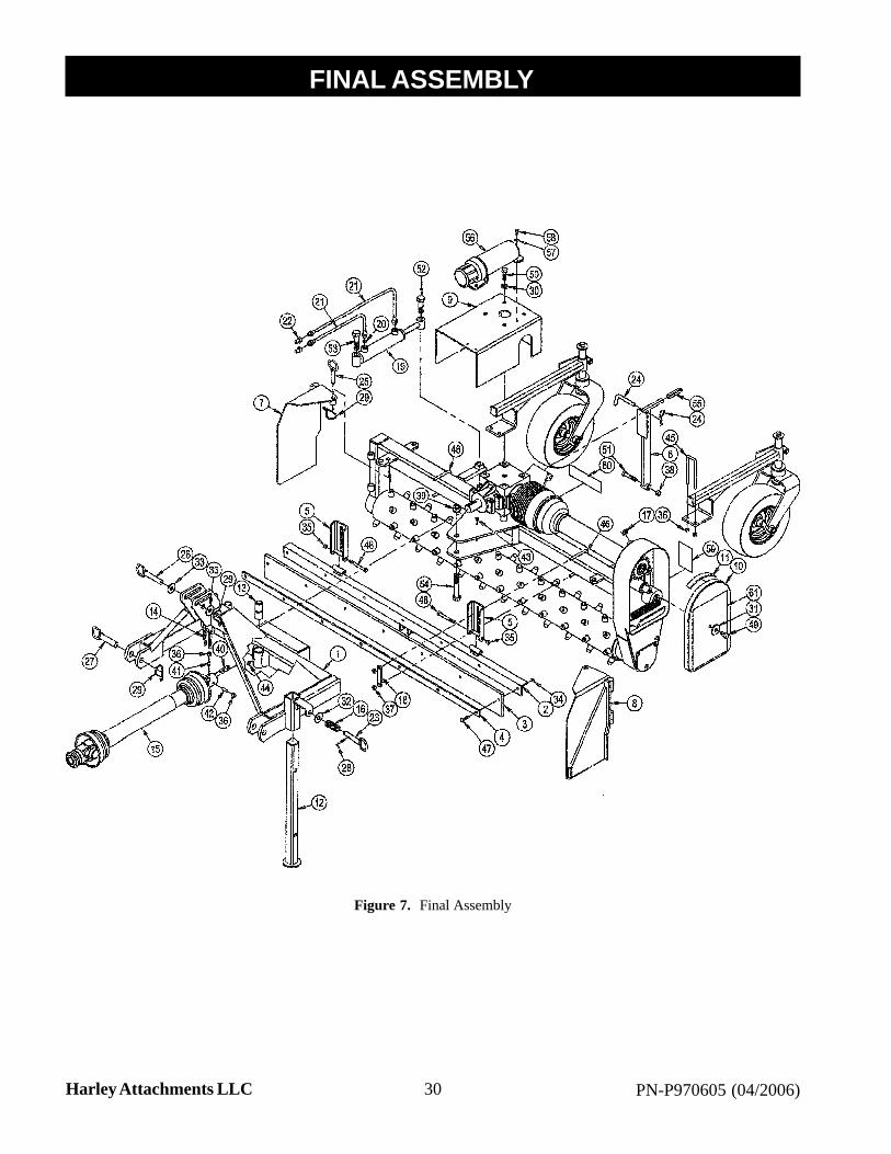
Figure 7. Final Assembly
FINAL ASSEMBLY1

31PN-P970605 (04/2006) Harley Attachments LLC
FINAL ASSEMBLY PARTS LIST1ITEMQTY PART NO DESCRIPTION
1 1 M5496 MAST FRAME2 1 M5512 MANUAL BARRIER MOUNT3 1 M5515 BARRIER4 1 M5424 BARRIER STRAP5 2 M5514 BARRIER PIVOT GUIDE6 1 M5508 BARRIER ADJUSTMENT BAR7 1 M5426 RIGHT END PLATE8 1 M5427 LEFT END PLATE9 1 M5489 GEARBOX SHIELD ASSEMBLY10 1 M4416 CHAIN CASE COVER11 1 M4418 COVER SEAL12 1 M5435 JACK STAND13 1 M10462 PIVOT BUSHING14 1 M6266 PTO SUPPORT CHAIN15 1 P400100-1 FRONT PTO FRONT HALF P400100-2 FRONT PTO REAR HALF16 1 P604500 COMPRESSION SPRING17 1 P278001 BREATHER PLUG18 2 M5518 U-BOLT STRAP19 1 P256250 HYDRAULIC CYLINDER 1-1/2" X 6"20 1 P270400 RESTRICTOR PLUG21 2 P246366 1/4 HOSE 8MP-6MB (66")22 2 P272600 MALE QUICK COUPLER23 1 M8263 JACK PIN24 1 P121150 1/2" X 3" BENT HITCH PIN ASSEMBLY25 2 M5433 5/8" X 2-1/2" GATE PIN26 1 M5003 3/4" X 3-3/4" UPPER HITCH PIN27 2 M8073 7/8" X 3-3/4" LOWER HITCH PIN28 1 P116204 1/8" X 1" COTTER PIN29 5 P622600 HAIR PIN CLIP30 4 P851108 1/2" LOCK WASHER31 1 M5009-5 3/16" X 1/2" X 1-3/4" WASHER32 1 P852001 16mm WASHER33 2 P850812 3/4" SAE WASHER34 7 P155350 5/16" TOP LOCK NUT35 6 P155450 3/8" TOP LOCK NUT36 2 P155400 3/8" HEX JAM NUT37 4 P158007 3/8" ELASTIC STOP NUT38 1 P155850 1/2" TOP LOCK NUT39 1 P157120 3/4"-10 TOP LOCK NUT40 1 M5000-5 5/16" X 2" SQUARE KEY41 1 P108610 3/8"-16 X 5/8" SET SCREW42 1 P108616 3/8"-16 X 1" SET SCREW43 2 P620000 1/4"-28 X 45° GREASE FITTING44 1 P620200 1/4"-28 STR GREASE FITTING45 2 P127200 3/8" X 1-1/2" X 5-1/2" U-BOLT46 2 P128393 3/8" X 3" X 4" U-BOLT47 7 P104506 5/16" X 1-1/2" CARRIAGE BOLT48 2 P100614 3/8" X 3-1/2" HEX BOLT49 1 P100804 1/2" X 1" HEX BOLT50 4 P100807 1/2" X 1-3/4" HEX BOLT51 1 P100810 1/2" X 2-1/2" HEX BOLT52 1 M5499 2-13/16" CYLINDER BOLT53 1 M5500 2-5/16" CYLINDER BOLT54 1 P101218 3/4" X 4-1/2" HEX BOLT55 1 P955850 1/2" SQUARED CAP X 3"56 1 P136000 MANUAL TUBE57 3 P850104 1/4" WASHER
ITEMQTY PART NO DESCRIPTION58 3 P100403 1/4" X 3/4" HEX BOLT59 1 P970003 DECAL: LUBRICATION60 1 P975800 DECAL: HARLEY61 1 P975919 DECAL: T5 COVER
32 PN-P970605 (04/2006)Harley Attachments LLC
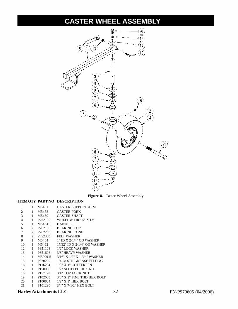
ITEMQTY PART NO DESCRIPTION1 1 M5451 CASTER SUPPORT ARM2 1 M5488 CASTER FORK3 1 M5450 CASTER SHAFT4 1 P752100 WHEEL & TIRE 5" X 13"5 1 M5454 HANDLE6 2 P762100 BEARING CUP7 2 P762200 BEARING CONE8 2 P852300 FELT WASHER9 1 M5464 1" ID X 2-1/4" OD WASHER10 1 M5462 17/32" ID X 2-1/4" OD WASHER12 1 P851108 1/2" LOCK WASHER13 1 P851606 3/8" HEAVY WASHER14 1 M5009-5 3/16" X 1/2" X 1-3/4" WASHER15 1 P620200 1/4-28 STR GREASE FITTING16 1 P116204 1/8" X 1" COTTER PIN17 1 P158006 1/2" SLOTTED HEX NUT18 1 P157120 3/4" TOP LOCK NUT19 1 P102608 3/8" X 2" FINE THD HEX BOLT20 1 P100804 1/2" X 1" HEX BOLT21 1 P101230 3/4" X 7-1/2" HEX BOLT
Figure 8. Caster Wheel Assembly
CASTER WHEEL ASSEMBLY1

33PN-P970605 (04/2006) Harley Attachments LLC
CLUTCH ASSEMBLY1
Figure 9. Clutch Assembly
ITEMQTY PART NO DESCRIPTION1 1 P400103 CLUTCH HUB2 1 P400104 CLUTCH BACK PLATE3 1 P400106 CLUTCH DRIVE SHAFT4 10 P400107 CLUTCH SPRING5 10 P400108 CLUTCH SPRING SPACER6 2 P400109 CLUTCH FIBER DISC

34 PN-P970605 (04/2006)Harley Attachments LLC
LIMITED WARRANTYHarley Attachments, LLC warrants its line of Harley equipment to be free from defects in material and factoryworkmanship for a period of twelve (12) months. Exception to this warranty period will be Harley Rock Pickers,which will carry a six (6) month warranty.
Warranty registration form must be filled out, signed by the customer and returned to Harley Attachments, LLCwithin thirty (30) days from the date of purchase before any warranty claim will be considered. Dealer rental units areconsidered sold units and the same warranty policy applies.
This warranty is limited exclusively to equipment manufactured by Harley Attachments, LLC and is subject toinspection by Harley Attachments, LLC to identify the nature and cause of failure. This company in no way warrantsbelts, bearings, hydraulics, chains, sprockets, tires or any other trade accessory not manufactured by Harley Attach-ments, LLC since these items are warranted separately by their respective manufactures.
This warranty shall become void if in the best judgement of Harley Attachments, LLC Inc the equipment has beensubject to misuse, negligence, alterations, and damage by accident or lack of required maintenance or if the product hasbeen used for a purpose for which it was not intended. Wear items such as, but not limited to, rollers and drive chainswill not be covered under warranty. Normal wear depreciation is not covered by warranty. Claims for equipmentdamaged in transit should be referred to the freight carrier. Harley Attachments, LLC will not be responsible fordamages incurred in transit.
Harley Attachments, LLC obligations under this warranty shall be limited to repair or replacement at its option ofthe equipment or trade accessories as they conform to this policy. Trade accessories such as but not limited tobearings, tires and wheels etc will be sent to the respective manufacturer for warranty consideration. Any warrantyreimbursement as related to these items will rely solely on the decision of each separate manufacture including HarleyAttachments, LLC Reimbursement on parts will be at dealer net and labor allowances are calculated according toHarley Attachments, LLC’s predetermined flat time and rate. Freight charges and misc. shop supplies are not coveredunder warranty.
Dealer’s responsibility is to fully explain the warranty policy to the customer before starting any repairs. Return thedefective parts (prepaid) along with a completed Harley Attachments, LLC Inc warranty form. All replacement partsused in warranty must be furnished by Harley Attachments, LLC (Please refer to warranty procedures). The sellingdealer has no authority to make any representation or promise on behalf of Harley Attachments, LLC or to modify theterms or conditions of this warranty in any way.
Owner’s responsibility is to complete and return the warranty registration within thirty (30) days from the date ofpurchase. Operate and maintain the equipment according to the recommendations in the owner’s manual. The owneris responsible for freight and transportation to and from the dealership or any service calls made by the dealer.
This warranty is subject to any conditions of supply, which may directly affect our ability to obtain materials ormanufacture replacement parts.
Harley Attachments, LLC Inc reserves the right to make improvements in design or change in specifications of itsproducts without notice and is not obligated to make the same improvements to equipment previously manufactured.
THERE IS NO OTHER EXPRESSED OR IMPLIED WARRANTY ON THIS PRODUCT OR ON ITS MER-CHANTABILITY OR ON ITS FITNESS. TO THE EXTENT ALLOWED BY LAW NIETHER HARLEY AT-TACHMENTS, LLC NOR THE SELLING HARLEY DEALER SHALL HAVE ANY RESPONSIBILITY FORLOSS OF USE OF THE PRODUCT, LOSS OF TIME, INCONVENIENCE, COMERCIAL LOSS OR CONSE-QUENTIAL DAMAGES.