operator’s manual power wave 355m...arc rays can burn. 4.a. use a shield with the proper filter...
TRANSCRIPT

POWER WAVE ® 355M
Operator’s Manual
Save for future reference
Date Purchased
Code: (ex: 10859)
Serial: (ex: U1060512345)
IM845-A | Issue D ate 12-Jan
© Lincoln Global, Inc. All Rights Reserved.
For use with machines having Code Numbers:
11141, 11489
Register your machine: www.lincolnelectric.com/register
Authorized Service and Distributor Locator: www.lincolnelectric.com/locator
Need Help? Call 1.888.935.3877 to talk to a Service Representative
Hours of Operation: 8:00 AM to 6:00 PM (ET) Mon. thru Fri.
After hours? Use “Ask the Experts” at lincolnelectric.comA Lincoln Service Representative will contact you no later than the following business day.
For Service outside the USA: Email: [email protected]
FOR ENGINEpowered equipment.
1.a. Turn the engine off before troubleshooting and maintenancework unless the maintenance work requires it to be running.
____________________________________________________1.b.Operate engines in open, well-ventilated
areas or vent the engine exhaust fumes outdoors.
____________________________________________________1.c. Do not add the fuel near an open flame
welding arc or when the engine is running.Stop the engine and allow it to cool beforerefueling to prevent spilled fuel from vaporiz-ing on contact with hot engine parts andigniting. Do not spill fuel when filling tank. Iffuel is spilled, wipe it up and do not startengine until fumes have been eliminated.
____________________________________________________1.d. Keep all equipment safety guards, covers and devices in
position and in good repair.Keep hands, hair, clothing andtools away from V-belts, gears, fans and all other movingparts when starting, operating or repairing equipment.
____________________________________________________
1.e. In some cases it may be necessary to remove safetyguards to perform requ i red ma intenance. Removeguards only when necessary and replace them when thema intenance requ ir ing the ir removal is complete.Always use the greatest care when working near movingparts.
___________________________________________________1.f. Do not put your hands near the engine fan.
Do not attempt to override the governor oridler by pushing on the throttle control rodswhile the engine is running.
___________________________________________________1.g. To prevent accidentally starting gasoline engines while
turning the engine or welding generator during maintenancework, disconnect the spark plug wires, distributor cap ormagneto wire as appropriate.
iSAFETYi
ARC WELDING CAN BE HAZARDOUS. PROTECT YOURSELF AND OTHERS FROM POSSIBLE SERIOUS INJURY OR DEATH.KEEP CHILDREN AWAY. PACEMAKER WEARERS SHOULD CONSULT WITH THEIR DOCTOR BEFORE OPERATING.
Read and understand the following safety highlights. For additional safety information, it is strongly recommended that youpurchase a copy of “Safety in Welding & Cutting - ANSI Standard Z49.1” from the American Welding Society, P.O. Box351040, Miami, Florida 33135 or CSA Standard W117.2-1974. A Free copy of “Arc Welding Safety” booklet E205 is availablefrom the Lincoln Electric Company, 22801 St. Clair Avenue, Cleveland, Ohio 44117-1199.
BE SURE THAT ALL INSTALLATION, OPERATION, MAINTENANCE AND REPAIR PROCEDURES AREPERFORMED ONLY BY QUALIFIED INDIVIDUALS.
WARNING
ELECTRIC AND MAGNETIC FIELDSmay be dangerous
2.a. Electric current flowing through any conductor causes localized Electric and Magnetic Fields (EMF). Welding current creates EMF fields around welding cables and welding machines
2.b. EMF fields may interfere with some pacemakers, andwelders having a pacemaker should consult their physicianbefore welding.
2.c. Exposure to EMF fields in welding may have other healtheffects which are now not known.
2.d. All welders should use the following procedures in order tominimize exposure to EMF fields from the welding circuit:
2.d.1. Route the electrode and work cables together - Securethem with tape when possible.
2.d.2. Never coil the electrode lead around your body.
2.d.3. Do not place your body between the electrode andwork cables. If the electrode cable is on your right side, the work cable should also be on your right side.
2.d.4. Connect the work cable to the workpiece as close aspossible to the area being welded.
2.d.5. Do not work next to welding power source.
1.h. To avoid scalding, do not remove theradiator pressure cap when the engine ishot.
CALIFORNIA PROPOSITION 65 WARNINGS
Diesel engine exhaust and some of its constituentsare known to the State of California to cause can-cer, birth defects, and other reproductive harm.
The engine exhaust from this product containschemicals known to the State of California to causecancer, birth defects, or other reproductive harm.
The Above For Diesel Engines The Above For Gasoline Engines
ARC RAYS can burn.4.a. Use a shield with the proper filter and cover
plates to protect your eyes from sparks andthe rays of the arc when welding or observingopen arc welding. Headshield and filter lensshould conform to ANSI Z87. I standards.
4.b. Use suitable clothing made from durable flame-resistantmaterial to protect your skin and that of your helpers fromthe arc rays.
4.c. Protect other nearby personnel with suitable, non-flammablescreening and/or warn them not to watch the arc nor exposethemselves to the arc rays or to hot spatter or metal.
ELECTRIC SHOCK cankill.3.a. The electrode and work (or ground) circuits
are electrically “hot” when the welder is on.Do not touch these “hot” parts with your bareskin or wet clothing. Wear dry, hole-free
gloves to insulate hands.
3.b. Insulate yourself from work and ground using dry insulation.Make certain the insulation is large enough to cover your fullarea of physical contact with work and ground.
In addition to the normal safety precautions, if weldingmust be performed under electrically hazardousconditions (in damp locations or while wearing wetclothing; on metal structures such as floors, gratings orscaffolds; when in cramped positions such as sitting,kneeling or lying, if there is a high risk of unavoidable oraccidental contact with the workpiece or ground) usethe following equipment:
• Semiautomatic DC Constant Voltage (Wire) Welder.• DC Manual (Stick) Welder.• AC Welder with Reduced Voltage Control.
3.c. In semiautomatic or automatic wire welding, the electrode,electrode reel, welding head, nozzle or semiautomaticwelding gun are also electrically “hot”.
3.d. Always be sure the work cable makes a good electricalconnection with the metal being welded. The connectionshould be as close as possible to the area being welded.
3.e. Ground the work or metal to be welded to a good electrical(earth) ground.
3.f. Maintain the electrode holder, work clamp, welding cable andwelding machine in good, safe operating condition. Replacedamaged insulation.
3.g. Never dip the electrode in water for cooling.
3.h. Never simultaneously touch electrically “hot” parts ofelectrode holders connected to two welders because voltagebetween the two can be the total of the open circuit voltageof both welders.
3.i. When working above floor level, use a safety belt to protectyourself from a fall should you get a shock.
3.j. Also see Items 6.c. and 8.
iiSAFETYii
FUMES AND GASEScan be dangerous.5.a. Welding may produce fumes and gases
hazardous to health. Avoid breathing thesefumes and gases. When welding, keepyour head out of the fume. Use enoughventilation and/or exhaust at the arc to keep
fumes and gases away from the breathing zone. Whenwelding with electrodes which require specialventilation such as stainless or hard facing (seeinstructions on container or MSDS) or on lead orcadmium plated steel and other metals or coatingswhich produce highly toxic fumes, keep exposure aslow as possible and within applicable OSHA PEL and ACGIH TLV limits using local exhaust or mechanicalventilation. In confined spaces or in some circum-stances, outdoors, a respirator may be required.Additional precautions are also required when weldingon galvanized steel.
5. b. The operation of welding fume control equipment is affectedby various factors including proper use and positioning ofthe equipment, maintenance of the equipment and the spe-cific welding procedure and application involved. Workerexposure level should be checked upon installation andperiodically thereafter to be certain it is within applicableOSHA PEL and ACGIH TLV limits.
5.c. Do not weld in locations near chlorinated hydrocarbon vaporscoming from degreasing, cleaning or spraying operations.The heat and rays of the arc can react with solvent vapors toform phosgene, a highly toxic gas, and other irritating prod-ucts.
5.d. Shielding gases used for arc welding can displace air andcause injury or death. Always use enough ventilation,especially in confined areas, to insure breathing air is safe.
5.e. Read and understand the manufacturer’s instructions for thisequipment and the consumables to be used, including thematerial safety data sheet (MSDS) and follow youremployer’s safety practices. MSDS forms are available fromyour welding distributor or from the manufacturer.
5.f. Also see item 1.b.
FOR ELECTRICALLYpowered equipment.
8.a. Turn off input power using the disconnectswitch at the fuse box before working onthe equipment.
8.b. Install equipment in accordance with the U.S. NationalElectrical Code, all local codes and the manufacturer’srecommendations.
8.c. Ground the equipment in accordance with the U.S. NationalElectrical Code and the manufacturer’s recommendations.
CYLINDER may explodeif damaged.7.a. Use only compressed gas cylinders
containing the correct shielding gas for theprocess used and properly operatingregulators designed for the gas and
pressure used. All hoses, fittings, etc. should be suitable forthe application and maintained in good condition.
7.b. Always keep cylinders in an upright position securelychained to an undercarriage or fixed support.
7.c. Cylinders should be located:• Away from areas where they may be struck or subjected tophysical damage.
• A safe distance from arc welding or cutting operations andany other source of heat, sparks, or flame.
7.d. Never allow the electrode, electrode holder or any otherelectrically “hot” parts to touch a cylinder.
7.e. Keep your head and face away from the cylinder valve outletwhen opening the cylinder valve.
7.f. Valve protection caps should always be in place and handtight except when the cylinder is in use or connected foruse.
7.g. Read and follow the instructions on compressed gascylinders, associated equipment, and CGA publication P-l,“Precautions for Safe Handling of Compressed Gases inCylinders,” available from the Compressed Gas Association1235 Jefferson Davis Highway, Arlington, VA 22202.
WELDING and CUTTINGSPARKS cancause fire or explosion.6.a. Remove fire hazards from the welding area.
If this is not possible, cover them to preventthe welding sparks from starting a fire.
Remember that welding sparks and hotmaterials from welding can easily go through small cracksand openings to adjacent areas. Avoid welding nearhydraulic lines. Have a fire extinguisher readily available.
6.b. Where compressed gases are to be used at the job site,special precautions should be used to prevent hazardoussituations. Refer to “Safety in Welding and Cutting” (ANSIStandard Z49.1) and the operating information for theequipment being used.
6.c. When not welding, make certain no part of the electrodecircuit is touching the work or ground. Accidental contactcan cause overheating and create a fire hazard.
6.d. Do not heat, cut or weld tanks, drums or containers until theproper steps have been taken to insure that such procedureswill not cause flammable or toxic vapors from substancesinside. They can cause an explosion even though they havebeen “cleaned”. For information, purchase “RecommendedSafe Practices for the Preparation for Welding and Cutting ofContainers and Piping That Have Held HazardousSubstances”, AWS F4.1 from the American Welding Society(see address above).
6.e. Vent hollow castings or containers before heating, cutting orwelding. They may explode.
6.f. Sparks and spatter are thrown from the welding arc. Wear oilfree protective garments such as leather gloves, heavy shirt,cuffless trousers, high shoes and a cap over your hair. Wearear plugs when welding out of position or in confined places.Always wear safety glasses with side shields when in awelding area.
6.g. Connect the work cable to the work as close to the weldingarea as practical. Work cables connected to the buildingframework or other locations away from the welding areaincrease the possibility of the welding current passingthrough lifting chains, crane cables or other alternate cir-cuits. This can create fire hazards or overheat lifting chainsor cables until they fail.
6.h. Also see item 1.c.
6.I. Read and follow NFPA 51B “ Standard for Fire PreventionDuring Welding, Cutting and Other Hot Work”, availablefrom NFPA, 1 Batterymarch Park, PO box 9101, Quincy, Ma022690-9101.
6.j. Do not use a welding power source for pipe thawing.
iiiSAFETYiii
Refer to http://www.lincolnelectric.com/safety for additional safety information.

ivSAFETYiv
PRÉCAUTIONS DE SÛRETÉPour votre propre protection lire et observer toutes les instructionset les précautions de sûreté specifiques qui parraissent dans cemanuel aussi bien que les précautions de sûreté générales suiv-antes:
Sûreté Pour Soudage A LʼArc1. Protegez-vous contre la secousse électrique:
a. Les circuits à lʼélectrode et à la piéce sont sous tensionquand la machine à souder est en marche. Eviter toujourstout contact entre les parties sous tension et la peau nueou les vétements mouillés. Porter des gants secs et sanstrous pour isoler les mains.
b. Faire trés attention de bien sʼisoler de la masse quand onsoude dans des endroits humides, ou sur un planchermetallique ou des grilles metalliques, principalement dans les positions assis ou couché pour lesquelles une grandepartie du corps peut être en contact avec la masse.
c. Maintenir le porte-électrode, la pince de masse, le câblede soudage et la machine à souder en bon et sûr étatdefonctionnement.
d.Ne jamais plonger le porte-électrode dans lʼeau pour lerefroidir.
e. Ne jamais toucher simultanément les parties sous tensiondes porte-électrodes connectés à deux machines à souderparce que la tension entre les deux pinces peut être letotal de la tension à vide des deux machines.
f. Si on utilise la machine à souder comme une source decourant pour soudage semi-automatique, ces precautionspour le porte-électrode sʼapplicuent aussi au pistolet desoudage.
2. Dans le cas de travail au dessus du niveau du sol, se protégercontre les chutes dans le cas ou on recoit un choc. Ne jamaisenrouler le câble-électrode autour de nʼimporte quelle partiedu corps.
3. Un coup dʼarc peut être plus sévère quʼun coup de soliel,donc:
a. Utiliser un bon masque avec un verre filtrant appropriéainsi quʼun verre blanc afin de se protéger les yeux du ray-onnement de lʼarc et des projections quand on soude ouquand on regarde lʼarc.
b. Porter des vêtements convenables afin de protéger lapeau de soudeur et des aides contre le rayonnement delʻarc.
c. Protéger lʼautre personnel travaillant à proximité ausoudage à lʼaide dʼécrans appropriés et non-inflammables.
4. Des gouttes de laitier en fusion sont émises de lʼarc desoudage. Se protéger avec des vêtements de protection libresde lʼhuile, tels que les gants en cuir, chemise épaisse, pan-talons sans revers, et chaussures montantes.
5. Toujours porter des lunettes de sécurité dans la zone desoudage. Utiliser des lunettes avec écrans lateraux dans leszones où lʼon pique le laitier.
6. Eloigner les matériaux inflammables ou les recouvrir afin deprévenir tout risque dʼincendie dû aux étincelles.
7. Quand on ne soude pas, poser la pince à une endroit isolé dela masse. Un court-circuit accidental peut provoquer unéchauffement et un risque dʼincendie.
8. Sʼassurer que la masse est connectée le plus prés possiblede la zone de travail quʼil est pratique de le faire. Si on placela masse sur la charpente de la construction ou dʼautresendroits éloignés de la zone de travail, on augmente le risquede voir passer le courant de soudage par les chaines de lev-age, câbles de grue, ou autres circuits. Cela peut provoquerdes risques dʼincendie ou dʼechauffement des chaines et descâbles jusquʼà ce quʼils se rompent.
9. Assurer une ventilation suffisante dans la zone de soudage.Ceci est particuliérement important pour le soudage de tôlesgalvanisées plombées, ou cadmiées ou tout autre métal quiproduit des fumeés toxiques.
10. Ne pas souder en présence de vapeurs de chlore provenantdʼopérations de dégraissage, nettoyage ou pistolage. Lachaleur ou les rayons de lʼarc peuvent réagir avec les vapeursdu solvant pour produire du phosgéne (gas fortement toxique)ou autres produits irritants.
11. Pour obtenir de plus amples renseignements sur la sûreté,voir le code “Code for safety in welding and cutting” CSAStandard W 117.2-1974.
PRÉCAUTIONS DE SÛRETÉ POURLES MACHINES À SOUDER ÀTRANSFORMATEUR ET ÀREDRESSEUR
1. Relier à la terre le chassis du poste conformement au code delʼélectricité et aux recommendations du fabricant. Le dispositifde montage ou la piece à souder doit être branché à unebonne mise à la terre.
2. Autant que possible, Iʼinstallation et lʼentretien du poste seronteffectués par un électricien qualifié.
3. Avant de faires des travaux à lʼinterieur de poste, la debranch-er à lʼinterrupteur à la boite de fusibles.
4. Garder tous les couvercles et dispositifs de sûreté à leurplace.

vv
Thank You for selecting a QUALITY product by Lincoln Electric. We want youto take pride in operating this Lincoln Electric Company product••• as much pride as we have in bringing this product to you!
Read this Operators Manual completely before attempting to use this equipment. Save this manual and keep ithandy for quick reference. Pay particular attention to the safety instructions we have provided for your protection.The level of seriousness to be applied to each is explained below:
WARNINGThis statement appears where the information must be followed exactly to avoid serious personal injury or loss of life.
This statement appears where the information must be followed to avoid minor personal injury or damage to this equipment.
CAUTION
Please Examine Carton and Equipment For Damage ImmediatelyWhen this equipment is shipped, title passes to the purchaser upon receipt by the carrier. Consequently, Claimsfor material damaged in shipment must be made by the purchaser against the transportation company at thetime the shipment is received.
Please record your equipment identification information below for future reference. This information can befound on your machine nameplate.
Product _________________________________________________________________________________
Model Number ___________________________________________________________________________
Code Number or Date Code_________________________________________________________________
Serial Number____________________________________________________________________________
Date Purchased___________________________________________________________________________
Where Purchased_________________________________________________________________________
Whenever you request replacement parts or information on this equipment, always supply the information youhave recorded above. The code number is especially important when identifying the correct replacement parts.
On-Line Product Registration- Register your machine with Lincoln Electric either via fax or over the Internet.• For faxing: Complete the form on the back of the warranty statement included in the literature packet
accompanying this machine and fax the form per the instructions printed on it.• For On-Line Registration: Go to our WEB SITE at www.lincolnelectric.com. Choose “Support” and then “Register
Your Product”. Please complete the form and submit your registration.
CUSTOMER ASSISTANCE POLICYThe business of The Lincoln Electric Company is manufacturing and selling high quality welding equipment, consumables, and cutting equip-ment. Our challenge is to meet the needs of our customers and to exceed their expectations. On occasion, purchasers may ask LincolnElectric for advice or information about their use of our products. We respond to our customers based on the best information in our posses-sion at that time. Lincoln Electric is not in a position to warrant or guarantee such advice, and assumes no liability, with respect to such infor-mation or advice. We expressly disclaim any warranty of any kind, including any warranty of fitness for any customerʼs particular purpose,with respect to such information or advice. As a matter of practical consideration, we also cannot assume any responsibility for updating orcorrecting any such information or advice once it has been given, nor does the provision of information or advice create, expand or alter anywarranty with respect to the sale of our products.
Lincoln Electric is a responsive manufacturer, but the selection and use of specific products sold by Lincoln Electric is solely within the controlof, and remains the sole responsibility of the customer. Many variables beyond the control of Lincoln Electric affect the results obtained inapplying these types of fabrication methods and service requirements.
Subject to Change – This information is accurate to the best of our knowledge at the time of printing. Please refer to www.lincolnelectric.comfor any updated information.

vi vi TABLE OF CONTENTSPage
Installation .......................................................................................................Section ATechnical Specifications ........................................................................................A-1Safety Precautions.................................................................................................A-2Select Suitable Location ........................................................................................A-2
Stacking ..........................................................................................................A-2Tilting...............................................................................................................A-2Input and Grounding Connections ..................................................................A-2Power Cord Connection ..................................................................................A-2Undercarriage Mountings................................................................................A-2
Output Cables, Connections and Limitations.........................................................A-3Negative Electrode Polarity ...................................................................................A-3Voltage Sensing ................................................................................................... A-4Power Wave to Semi-automatic Power Feed Wire Feeder Interconnections........A-5System Description................................................................................................A-5System Set-Up...............................................................................................A-6, A-7Welding with Multiple Power Waves......................................................................A-8Control Cable Specifications..................................................................................A-8Multiple Arc Unsynchronized sense and work leads .............................................A-9I / O Receptacle Specifications............................................................................A-10
Dip Switch Settings and Locations...............................................................A-10Control Board Dip Switch ..............................................................................A-10________________________________________________________________________
Operation .........................................................................................................Section BSafety Precautions.................................................................................................B-1General Description...............................................................................................B-1Recommended Processes and Equipment ...........................................................B-1
Recommended Processes ..............................................................................B-1Required Equipment .......................................................................................B-2Limitations .......................................................................................................B-2Duty Cycle and Time Period ...........................................................................B-2Case Front Controls ........................................................................................B-2Nominal Procedures........................................................................................B-3Fringe Procedures...........................................................................................B-3Making a Weld ................................................................................................B-3Welding Adjustment ........................................................................................B-3Constant Voltage Welding...............................................................................B-4Pulse Welding .................................................................................................B-5TIG GTAW, SMAW, and Arc Gouging ............................................................B-6Power Mode and Recommended Welding Procedures ..................................B-7________________________________________________________________________
Accessories .....................................................................................................Section COptional Equipment ...............................................................................................C-1
Factory Installed..............................................................................................C-1Field Installed..................................................................................................C-1Compatible Lincoln Equipment________________________________________________________________________
Maintenance ....................................................................................................Section DSafety Precautions ................................................................................................D-1Capacitor Discharge Procedure ............................................................................D-1Routine Maintenance.............................................................................................D-1Periodic Maintenance............................................................................................D-1Calibration Specification........................................................................................D-1________________________________________________________________________
Troubleshooting ..............................................................................................Section EHow to use Troubleshooting Guide .......................................................................E-1Using the Status LED to Troubleshoot System Problems .....................................E-2Troubleshooting Guide.............................................................................E-3 thru E-7________________________________________________________________________
Wiring Diagram ............................................................................................Section F-1Connection Diagram ....................................................................................Section F-2Dimension Print............................................................................................Section F-3________________________________________________________________________Parts Lists...............................................................................................................P-418________________________________________________________________________

A-1INSTALLATION
POWER WAVE® 355M
A-1
TECHNICAL SPECIFICATIONS - POWER WAVE® 355MINPUT AC VOLTAGE & DC OUTPUT
Product Ordering Input AC Rated DC Output Output Weight DimensionsName Information Voltage Amps/Volts/Duty Cycle Range with Cord HxWxD
(continuous)
200 350A / 34V / 60% 14.8” x 13.3” xPOWER K2368-1 208-230/ 27.8”* WAVE 380-400/ AMPS (81.5 lbs.) (373 x 338 x355M 415-460/ 5-425 (37.0 kg.) 706*)mm
575 300A / 32V /100%1& 3 Phase * Includes Handles
50/60 Hz
* Overall Length Including Handle, 21.6” (549mm) without handle.Insulation Class 180 (H)
Voltage
200
208230380
400
415460575
200208230380400415460575
Phases
1
111
1
111
33333333
300Amps @32Volts(100%)
NotRecommended
7669Not
RecommendedNot
Recommended413631
4139362322221916
350Amps @34Volts(60%)
NotRecommended
9485Not
RecommendedNot
Recommended644237
5050422827262318
Line CordAWG
24
---
688
66888888
Fuse size
---
125A125A
---
---
80A70A50A
80A80A70A40A40A40A40A30A
POWER WAVE® 355M INPUT CURRENT
OUTPUT CABLES, CONNECTIONS AND LIMITATIONS
Recommended Fuse Sizes Base On The U.S. National Electrical Code And Maximum Machine Outputs
Input 50/60 Hz Output Recommended
Note 1. Not rated is indicated by 4-xʼs in the box on the rating plate.Note 2. When operating on these inputs, the line cord should be changed to an input conductor of 6 AWG or larger.
Select The output cable size based upon the following chart.*Cable sizes for Combined Length of Electrode and Work Cable (Copper) 75°C rated:
DUTY CYCLE100%60%
CURRENT300350
LENGTH UP 200FT. (61m)2/02/0
200-250 FT. (61-76m)2/02/0
Notes
Note 1
Note 2Note 2Note 1
Note 1
Note 2
Note 2Note 2
*Lincoln Electric recommends using a minimum of 2/0 welding cable for pulse welding.

A-2INSTALLATION
POWER WAVE® 355M
A-2
SELECT SUITABLE LOCATION
The Invertec POWER WAVE® 355M will operate inharsh environments. Even so, it is important that sim-ple preventative measures are followed in order toassure long life and reliable operation.
• The machine must be located where there is free cir-culation of clean air such that air movement in theback, out the sides and bottom will not be restricted.
• Dirt and dust that can be drawn into the machineshould be kept to a minimum. Failure to observethese precautions can result in excessive operatingtemperatures and nuisance shutdown.
• Keep machine dry. Shelter from rain and snow. Donot place on wet ground or in puddles.
• DO NOT MOUNT OVER COMBUSTIBLE SURFACES.
Where there is a combustible surfacedirectly under stationary or fixed elec-trical equipment, that surface shall becovered with a steel plate at least.06”(1.6mm) thick, which shall extend
not less than 5.90”(150mm) beyond the equipmenton all sides.-----------------------------------------------------------------------STACKINGPOWER WAVE® 355M cannot be stacked.
TILTINGPlace the machine directly on a secure, level surfaceor on a recommended undercarriage. The machinemay topple over if this procedure is not followed.
INPUT AND GROUNDING CONNECTIONS• Only a qualified electrician should connect the
Invertec POWER WAVE® 355M. Installation shouldbe made in accordance w i th the appropriateNational Electrical Code, all local codes and theinformation detailed below.
• When received directly from the factory, multiplevoltage machines are internally connected for460VAC. If 460VAC is the desired input, then themachine may be connected to the power systemwithout any setup required inside the machine.
SAFETY PRECAUTIONS
ELECTRIC SHOCK can kill. • TURN THE INPUT POWER OFF ATTHE DISCONNECT SWITCH BEFOREATTEMPTING TO CONNECT OR DIS-CONNECT INPUT POWER LINES,
OUTPUT CABLES, OR CONTROL CABLES.• Only qualified personnel should perform this
installation.• Connect the green or green/yellow lead of the
power cord to ground per U.S.NationalElectrical Code.
----------------------------------------------------------------------
WARNING
• Initial 200VAC - 415VAC and 575VAC operationwill require an Input voltage panel setup.
• Open the access panel on the rear of the machine.• For 200 or 230: Position the large switch to 200-
230.• For higher voltages: Position the large switch to380-575.
• Move the "A" lead to the appropriate terminal.
POWER CORD CONNECTIONA 10 ft.(3.5m) power cord is provided and wired intothe machine. Follow the power cord connectioninstructions.
• Incorrect connection may result in equipmentdamage.
-----------------------------------------------------------------------
Single Phase InputConnect green or green/yellow lead to ground perNational Electrical Code.Connect black and white leads to power.Wrap red lead with tape to provide 600V insulation.Three Phase InputConnect green or green/yellow lead to ground perNational Electric Code.Connect black, red and white leads to power.
UNDERCARRIAGE MOUNTINGS
WARNINGWARNING
AVISO DE
PRECAUCION
ATTENTION
!
!
!
!
Lorem ipsum dolor sit amet consectetuer adipiscing
Lorem ipsum dolor sit amet consectetuer adipiscing
elit, ed diam nonummy nibh euismod tincidunt ut
elit, ed diam nonummy nibh euismod tincidunt ut
laoreet dolore magna aliquam erat
laoreet dolore magna aliquam erat
Lorem ipsum dolor sit amet consectetuer adipiscing
Lorem ipsum dolor sit amet consectetuer adipiscing
elit, ed diam nonummy nibh euismod tincidunt ut
elit, ed diam nonummy nibh euismod tincidunt ut
laoreet dolore magna aliquam erat
laoreet dolore magna aliquam erat
Lorem ipsum dolor sit amet consectetuer adipiscing
Lorem ipsum dolor sit amet consectetuer adipiscing
elit, ed diam nonummy nibh euismod tincidunt ut
elit, ed diam nonummy nibh euismod tincidunt ut
laoreet dolore magna aliquam erat
laoreet dolore magna aliquam erat
Lorem ipsum dolor sit amet consectetuer adipiscing
Lorem ipsum dolor sit amet consectetuer adipiscing
elit, ed diam nonummy nibh euismod tincidunt ut
elit, ed diam nonummy nibh euismod tincidunt ut
laoreet dolore magna aliquam erat
laoreet dolore magna aliquam erat
Lorem ipsum dolor sit amet consectetuer adipiscing
Lorem ipsum dolor sit amet consectetuer adipiscing
elit, ed diam nonummy nibh euismod tincidunt ut
elit, ed diam nonummy nibh euismod tincidunt ut
laoreet dolore magna aliquam erat
laoreet dolore magna aliquam erat
Lorem ipsum dolor sit amet consectetuer adipiscing
Lorem ipsum dolor sit amet consectetuer adipiscing
elit, ed diam nonummy nibh euismod tincidunt ut
elit, ed diam nonummy nibh euismod tincidunt ut
laoreet dolore magna aliquam erat
laoreet dolore magna aliquam erat
Lorem ipsum dolor sit amet consectetuer adipiscing
Lorem ipsum dolor sit amet consectetuer adipiscing
elit, ed diam nonummy nibh euismod tincidunt ut
elit, ed diam nonummy nibh euismod tincidunt ut
laoreet dolore magna aliquam erat
laoreet dolore magna aliquam erat
Lorem ipsum dolor sit amet consectetuer adipiscing
Lorem ipsum dolor sit amet consectetuer adipiscing
elit, ed diam nonummy nibh euismod tincidunt ut
elit, ed diam nonummy nibh euismod tincidunt ut
laoreet dolore magna aliquam erat
laoreet dolore magna aliquam erat
Lorem ipsum dolor sit amet consectetuer adipiscing
Lorem ipsum dolor sit amet consectetuer adipiscing
elit, ed diam nonummy nibh euismod tincidunt ut
elit, ed diam nonummy nibh euismod tincidunt ut
laoreet dolore magna aliquam erat
laoreet dolore magna aliquam erat
Lorem ipsum dolor sit amet consectetuer adipiscing
Lorem ipsum dolor sit amet consectetuer adipiscing
elit, ed diam nonummy nibh euismod tincidunt ut
elit, ed diam nonummy nibh euismod tincidunt ut
laoreet dolore magna aliquam erat
laoreet dolore magna aliquam erat
Lorem ipsum dolor sit amet consectetuer adipiscing
Lorem ipsum dolor sit amet consectetuer adipiscing
elit, ed diam nonummy nibh euismod tincidunt ut
elit, ed diam nonummy nibh euismod tincidunt ut
laoreet dolore magna aliquam erat
laoreet dolore magna aliquam erat
Lorem ipsum dolor sit amet consectetuer adipiscing
Lorem ipsum dolor sit amet consectetuer adipiscing
elit, ed diam nonummy nibh euismod tincidunt ut
elit, ed diam nonummy nibh euismod tincidunt ut
laoreet dolore magna aliquam erat
laoreet dolore magna aliquam erat
Lorem ipsum dolor sit amet consectetuer adipiscing
Lorem ipsum dolor sit amet consectetuer adipiscing
elit, ed diam nonummy nibh euismod tincidunt ut
elit, ed diam nonummy nibh euismod tincidunt ut
laoreet dolore magna aliquam erat
laoreet dolore magna aliquam erat
Lorem ipsum dolor sit amet consectetuer adipiscing
Lorem ipsum dolor sit amet consectetuer adipiscing
elit, ed diam nonummy nibh euismod tincidunt ut
elit, ed diam nonummy nibh euismod tincidunt ut
laoreet dolore magna aliquam erat
laoreet dolore magna aliquam erat
Lorem ipsum dolor sit amet consectetuer adipiscing
Lorem ipsum dolor sit amet consectetuer adipiscing
elit, ed diam nonummy nibh euismod tincidunt ut
elit, ed diam nonummy nibh euismod tincidunt ut
laoreet dolore magna aliquam erat
laoreet dolore magna aliquam erat
Lorem ipsum dolor sit amet consectetuer adipiscing
Lorem ipsum dolor sit amet consectetuer adipiscing
elit, ed diam nonummy nibh euismod tincidunt ut
elit, ed diam nonummy nibh euismod tincidunt ut
laoreet dolore magna aliquam erat
laoreet dolore magna aliquam erat
Lorem ipsum dolor sit amet consectetuer adipiscing
Lorem ipsum dolor sit amet consectetuer adipiscing
elit, ed diam nonummy nibh euismod tincidunt ut
elit, ed diam nonummy nibh euismod tincidunt ut
laoreet dolore magna aliquam erat
laoreet dolore magna aliquam erat
Lorem ipsum dolor sit amet consectetuer adipiscing
Lorem ipsum dolor sit amet consectetuer adipiscing
elit, ed diam nonummy nibh euismod tincidunt ut
elit, ed diam nonummy nibh euismod tincidunt ut
laoreet dolore magna aliquam erat
laoreet dolore magna aliquam erat
Lorem ipsum dolor sit amet consectetuer adipiscing
Lorem ipsum dolor sit amet consectetuer adipiscing
elit, ed diam nonummy nibh euismod tincidunt ut
elit, ed diam nonummy nibh euismod tincidunt ut
laoreet dolore magna aliquam erat
laoreet dolore magna aliquam erat
WARNING
REMOTE
POWER
OFF
ON
P O W
E R W A V E 3
5 5
GREEN ORGREEN/YELLOWRED
BLACK
WHITE
5.50
10.00
MOUNTING HOLE LOCATIONS
M19527
1/4-20 NUT (4 PLACES)
NOTE: MOUNTING SCREWS CA
10/01
N NOT PROTRUDE MORE THAN 0.5 INCHES INSIDE THE MACHINE.
11.84
3.50
CAUTION
CAUTION

less than 50 ft.(15.24m). (See Figure A.4.)
Output connections on some Power Waves® are madevia 1/2-13 threaded output studs located beneath thespring loaded output cover at the bottom of the casefront.
Most welding applications run with the electrode beingpositive (+). For those applications, connect the elec-trode cable between the wire feeder and the positive(+) output Twist-Mate terminal on the power source.Connect the other end of the electrode cable to thewire drive feed plate. The electrode cable lug must beagainst the feed plate. Be sure the connection to thefeed plate makes tight metal-to-metal electrical con-tact. The electrode cable should be sized according tothe specifications given in the output cable connec-tions section. Connect a work lead from the negative(-) power source output Twist-Mate terminal to thework piece. The work piece connection must be firmand secure, especially if pulse welding is planned.
For additional Safety information regarding the elec-trode and work cable set-up, See the standard "SAFE-TY INFORMATION" located in the front of theInstruction Manuals.
Excessive voltage drops caused by poor workpiece connections often result in unsatisfactorywelding performance.------------------------------------------------------------------------NEGATIVE ELECTRODE POLARITYWhen negative electrode polarity is required, such asin some Innershield applications, reverse the outputconnections at the power source (electrode cable tothe negative (-) Twist-Mate terminal, and work cableto the positive (+) Twist-Mate terminal.
When operating with negative electrode polarity the"Electrode Sense Polarity" DIP switch must be set tothe "Negative" position on the Wire Drive Feed HeadPC Board. The default setting of the switch is positiveelectrode polarity. Consult the Power Feed instructionmanual for further details.
A-3INSTALLATION
POWER WAVE® 355M
A-3
OUTPUT CABLES, CONNECTIONS ANDLIMITATIONSConnect a work lead of sufficient size and length (pertable A.1) between the proper output terminal on thepower source and the work. Be sure the connection tothe work makes tight metal-to-metal electrical contact.To avoid interference problems with other equipmentand to achieve the best possible operation, route allcables directly to the work or wire feeder. Avoidexcessive lengths and do not coil excess cable.
When using an inverter type power source like thePower Waves®, use the largest welding (electrodeand work) cables that are practical. At least 2/0copper wire - even if the average output currentwould not normally require it. When pulsing, thepulse current can reach very high levels. Voltagedrops can become excessive, leading to poorwelding characteristics, if undersized weldingcables are used.-----------------------------------------------------------------------CABLE INDUCTANCE, AND ITS EFFECTSON PULSE WELDINGFor Pulse Welding processes, cable inductance willcause the welding performance to degrade. For thetotal welding loop length less than 50 ft.(15.24m), tradi-tional welding cables may be used without any effectson welding performance. For the total welding looplength greater than 50 ft.(15.24m)), the K1796 CoaxialWelding Cables are recommended. The welding looplength is defined as the total of electrode cable length(A) + work cable length (B) + work length (C) (SeeFigure A.3).
For long work piece lengths, a sliding ground shouldbe considered to keep the total welding loop length
CAUTION
CAUTION
B
A
C
FIGURE A.3
POWERWAVE
WORK
A
C
B
POWERWAVE
FIGURE A.4
K1796 COAXIAL CABLE
MEASURE FROM ENDOF OUTER JACKET OFCABLE
C
A
B
WORK
SLIDING WORK
A-4INSTALLATION
POWER WAVE® 355M
A-4
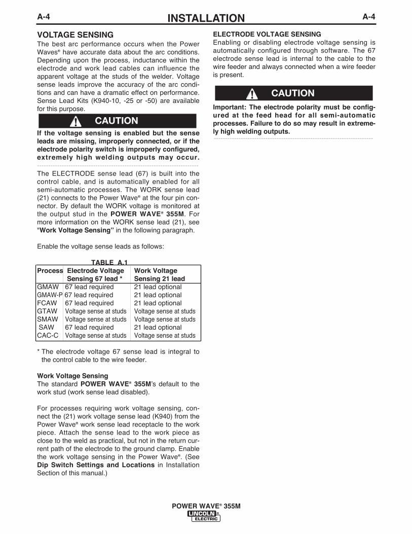
VOLTAGE SENSINGThe best arc performance occurs when the PowerWaves® have accurate data about the arc conditions.Depending upon the process, inductance within theelectrode and work lead cables can influence theapparent voltage at the studs of the welder. Voltagesense leads improve the accuracy of the arc condi-tions and can have a dramatic effect on performance.Sense Lead Kits (K940-10, -25 or -50) are availablefor this purpose.
If the voltage sensing is enabled but the senseleads are missing, improperly connected, or if theelectrode polarity switch is improperly configured,extremely high welding outputs may occur.------------------------------------------------------------------------The ELECTRODE sense lead (67) is built into thecontrol cable, and is automatically enabled for allsemi-automatic processes. The WORK sense lead(21) connects to the Power Wave® at the four pin con-nector. By default the WORK voltage is monitored atthe output stud in the POWER WAVE® 355M. Formore information on the WORK sense lead (21), see"Work Voltage Sensing” in the following paragraph.
Enable the voltage sense leads as follows:
TABLE A.1Process Electrode Voltage Work Voltage
Sensing 67 lead * Sensing 21 leadGMAW 67 lead required 21 lead optionalGMAW-P 67 lead required 21 lead optionalFCAW 67 lead required 21 lead optionalGTAW Voltage sense at studs Voltage sense at studsSMAW Voltage sense at studs Voltage sense at studsSAW 67 lead required 21 lead optionalCAC-C Voltage sense at studs Voltage sense at studs
* The electrode voltage 67 sense lead is integral tothe control cable to the wire feeder.
Work Voltage SensingThe standard POWER WAVE® 355Mʼs default to thework stud (work sense lead disabled).
For processes requiring work voltage sensing, con-nect the (21) work voltage sense lead (K940) from thePower Wave® work sense lead receptacle to the workpiece. Attach the sense lead to the work piece asclose to the weld as practical, but not in the return cur-rent path of the electrode to the ground clamp. Enablethe work voltage sensing in the Power Wave®. (SeeDip Switch Settings and Locations in InstallationSection of this manual.)
ELECTRODE VOLTAGE SENSINGEnabling or disabling electrode voltage sensing isautomatically configured through software. The 67electrode sense lead is internal to the cable to thewire feeder and always connected when a wire feederis present.
Important: The electrode polarity must be config-ured at the feed head for all semi-automaticprocesses. Failure to do so may result in extreme-ly high welding outputs.-----------------------------------------------------------------------
CAUTION
CAUTION

POWER WAVE TO SEMI-AUTOMATICPOWER FEED WIRE FEEDER INTERCON-NECTIONS
The POWER WAVE® 355M and semi-automat icPower Feed family communicate via a 5 conductorcontrol cable (K1543). The control cable consists oftwo power leads, one twisted pair for digital communi-cation, and one lead for voltage sensing. The cablesare designed to be connected end to end for ease ofextension. The output receptacle on the POWERWAVE® 355M is on the case front. The input recepta-cle on the Power Feed is typically located at the backof the feeder, or on the bottom of the user interface.
Due to the flexibility of the platform the configurationmay vary. The following is a general description of thesystem. For specific configuration information, consultthe semi-automatic Power Feed instruction manual.
SYSTEM DESCRIPTION
The POWER WAVE® 355M and Power Feed M family ofproducts utilize a digital communication system calledArcLink. Simply put, ArcLink allows large amounts ofinformation to be passed at very high speeds betweencomponents (nodes) in the system. The system requiresonly two wires for communication, and because of itsbus-like structure, the components may be connected tothe network in any order, thus simplifying the system set-up.
Each "system" must contain only one power source.The number of wire feeders is determined by the typeof wire feeder. Refer to the wire feeder instructionmanual for details
A-5INSTALLATION
POWER WAVE® 355M
A-5

A-6INSTALLATION A-6
POWER WAVE® 355M
CONFIGURING THE SYSTEM
The power source will “Auto Map” the system eliminat-ing most of the need to set DIP switches to configurethe system.
If a system can not be “Auto Mapped” then the statuslight on the power source will blink green fast and thewelder output will be disabled.
If a system is not “Auto-mappable”, then consult theinstruction manual for the accessory being used forconfiguration information about DIP switch settings, orconsult your local Lincoln sales representative.
POWER WAVE®
355M
ROBOT PLC CONTROLLER
ANALOG INTERFACE
etc.
POWER WAVE® 355M
POWER WAVE®
355M
POWER WAVE®
355M
FEED HEAD
FEED HEAD 1
CONTROL BOX
SINGLE HEAD FEEDER DUAL HEAD FEEDER
SINGLE HEAD BOOM FEEDER
PF-10R
SINGLE HEAD BOOM FEEDER
UP TO 4 WIRE FEEDERSALLOWED
UP TO 4 FEED HEADSALLOWED
WIREDRIVEMODULE

A-7INSTALLATION
POWER WAVE® 355M
A-7
In this case the individual feed heads need to be assigned to the dual head control and the POWER WAVE®
355M auto mapping disabled and the Equipment Groups set on (See Figure A-8). (See the Feeder documenta-tion for information on setting the feeder DIP switches)
System that is NOT "Auto Mappable"
POWER WAVE® 355M
POWER WAVE® 355M
POWER WAVE®
355M
DUAL HEAD
DUAL HEAD
ALTERNATE HARD AUTOMATIC APPLICATION(using a User Interface, Wire Drive Module, and POWER FEED-10R)
COMBINATION HARD AUTOMATION APPLICATION(w/ Semi-Auto Feeder, Wire Drive Module, and POWER FEED-10R)
DUAL HEAD BOOM FEEDER(using two single heads)
PF-10R
FH-1 FH-2
PF-10RWIREDRIVEMODULE
(FH1)
WIREDRIVEMODULE
(FH1)
A-8INSTALLATION
POWER WAVE® 355M
A-8
Connect All WorkSense Leads at the Endof the Joint
Connect All WeldingWork Leads at theBeginning of the Joint
TravelDirection
POWER WAVE 355MPOWER WAVE 355M
®®
TWO POWER WAVES®
FIGURE A.6
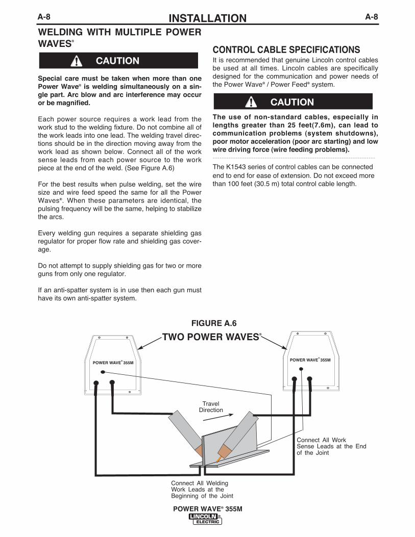
CONTROL CABLE SPECIFICATIONSIt is recommended that genuine Lincoln control cablesbe used at all times. Lincoln cables are specificallydesigned for the communication and power needs ofthe Power Wave® / Power Feed® system.
The use of non-standard cables, especially inlengths greater than 25 feet(7.6m), can lead tocommunication problems (system shutdowns),poor motor acceleration (poor arc starting) and lowwire driving force (wire feeding problems).------------------------------------------------------------------------The K1543 series of control cables can be connectedend to end for ease of extension. Do not exceed morethan 100 feet (30.5 m) total control cable length.
WELDING WITH MULTIPLE POWERWAVES®
Special care must be taken when more than onePower Wave® is welding simultaneously on a sin-gle part. Arc blow and arc interference may occuror be magnified.
Each power source requires a work lead from thework stud to the welding fixture. Do not combine all ofthe work leads into one lead. The welding travel direc-tions should be in the direction moving away from thework lead as shown below. Connect all of the worksense leads from each power source to the workpiece at the end of the weld. (See Figure A.6)
For the best results when pulse welding, set the wiresize and wire feed speed the same for all the PowerWaves®. When these parameters are identical, thepulsing frequency will be the same, helping to stabilizethe arcs.
Every welding gun requires a separate shielding gasregulator for proper flow rate and shielding gas cover-age.
Do not attempt to supply shielding gas for two or moreguns from only one regulator.
If an anti-spatter system is in use then each gun musthave its own anti-spatter system.
CAUTION
CAUTION
A-9INSTALLATION
POWER WAVE® 355M
A-9
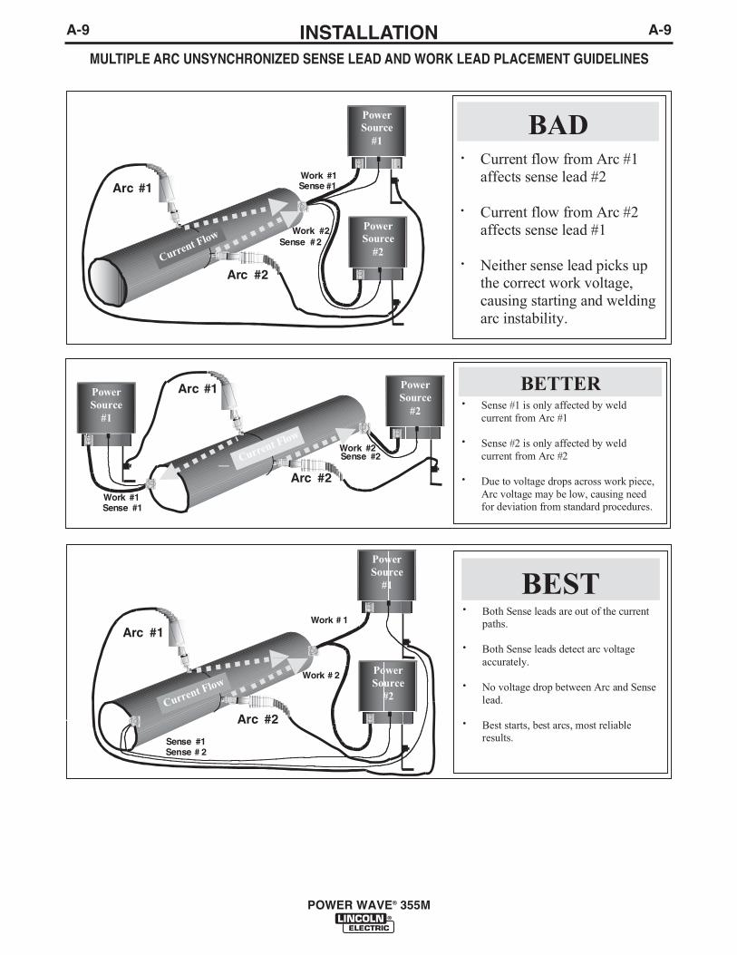
MULTIPLE ARC UNSYNCHRONIZED SENSE LEAD AND WORK LEAD PLACEMENT GUIDELINES

A-10INSTALLATION
POWER WAVE® 355M
A-10
I / O RECEPTACLE SPECIFICATIONSTABLE A.2
WIRE FEEDER RECEPTACLE PIN LEAD# FUNCTIONA 53 Communication Bus LB 54 Communication Bus HC 67A Electrode Voltage SenseD 52 0vdc -E 51 +40vdc +
TABLE A.3VOLTAGE SENSE RECEPTACLE
PIN LEAD# FUNCTION3 21A Work Voltage Sense
TABLE A.4RS232 RECEPTACLE
PIN LEAD# FUNCTION2 253 RS232 Receive3 254 RS232 Transmit4 # Pin55 # Pin46 # # Pin2020 # # Pin67 251 RS232 Common
DIP SWITCH SETTINGS AND LOCATIONSDIP switches on the P.C. Boards allow for custom configuration ofthe Power Wave®. To access the DIP switches:
ELECTRIC SHOCK can kill.
1. Turn off power to the power source at the dis-connect switch.
• Insulate yourself from the work and ground.• Always wear dry insulating gloves.
------------------------------------------------------------------------------------------2. Remove the wrap around cover from the power source.3. The control board is on the center assembly facing the case front.Locate the 8-position DIP switch and look for switch 8 of the DIPswitch.
4. Using a pencil or other small object, slide the switch to the OFFposition if the work sense lead is NOT connected. Conversely, slidethe switch to the ON position if the work sense lead is present.
5. Replace the wrap around and screws. The PC board will “read” theswitch at power up, and configure the work voltage sense leadappropriately.
CONTROL BOARD DIP SWITCH:switch 1 = reserved for future useswitch 2 = reserved for future useswitch 3 = equipment group 1 selcted (default=off)switch 4 = equipment group 2 selcted (default=off)switch 5 = reserved for future useswitch 6 = reserved for future useswitch 7 = auto mappingswitch 8 = work sense lead
(See Figure A.8 for Dual Head Boom Feeder)
switch 8* work sense leadoff work sense lead not connectedon work sense lead connected
*Factory setting for Switch 8 is OFF.
switch 7 auto mappingoff auto mapping enable-default
on auto mapping disabled
CONTROL BOARD (DIP Switch Location)
FIGURE A.7
WARNING
} 40VDC
FIGURE A.8
GENERAL DESCRIPTIONThe POWER WAVE® 355M semi-automatic powersource is designed to be a part of a modular, multi-process welding system. Depending on configuration,it can support constant current, constant voltage, con-stant power and pulse welding modes.
The POWER WAVE® 355M power source is designedto be used with the semi automatic family of PowerFeed® wire feeders, operating as a system. Each com-ponent in the system has special circuitry to "talk with"the other system components, so each component(power source, wire feeder, user interface) knowswhat the other is doing at all times. These compo-nents communicate with Arclink..
The POWER WAVE® 355M is a high performance,digitally controlled inverter welding power sourcecapable of complex, high-speed waveform control.Properly equipped, it can support the GMAW, GMAW-P, FCAW, SMAW, GTAW, and CAC-A processes. Itcarries an output rating of 350 Amps, 34 Volts at 60%duty cycle and 300 Amps, 32 volts at 100% dutycycle.
RECOMMENDED PROCESSES ANDEQUIPMENT
RECOMMENDED PROCESSESThe POWER WAVE® 355M can be set up in a numberof configurations, some requiring optional equipmentor welding programs. Each machine is factory prepro-grammed with multiple welding procedures, typicallyincluding GMAW, GMAW-P, FCAW, GTAW, andCAC-A for a variety of materials, including mild steel,stainless steel, cored wires, and aluminum.
The POWER WAVE® 355M is recommended for semi-automatic welding, and may also be suitable for basichard automation applications.
• This Power Wave® is not recommended for process-es other than those listed.
B-1OPERATIONB-1
POWER WAVE® 355M
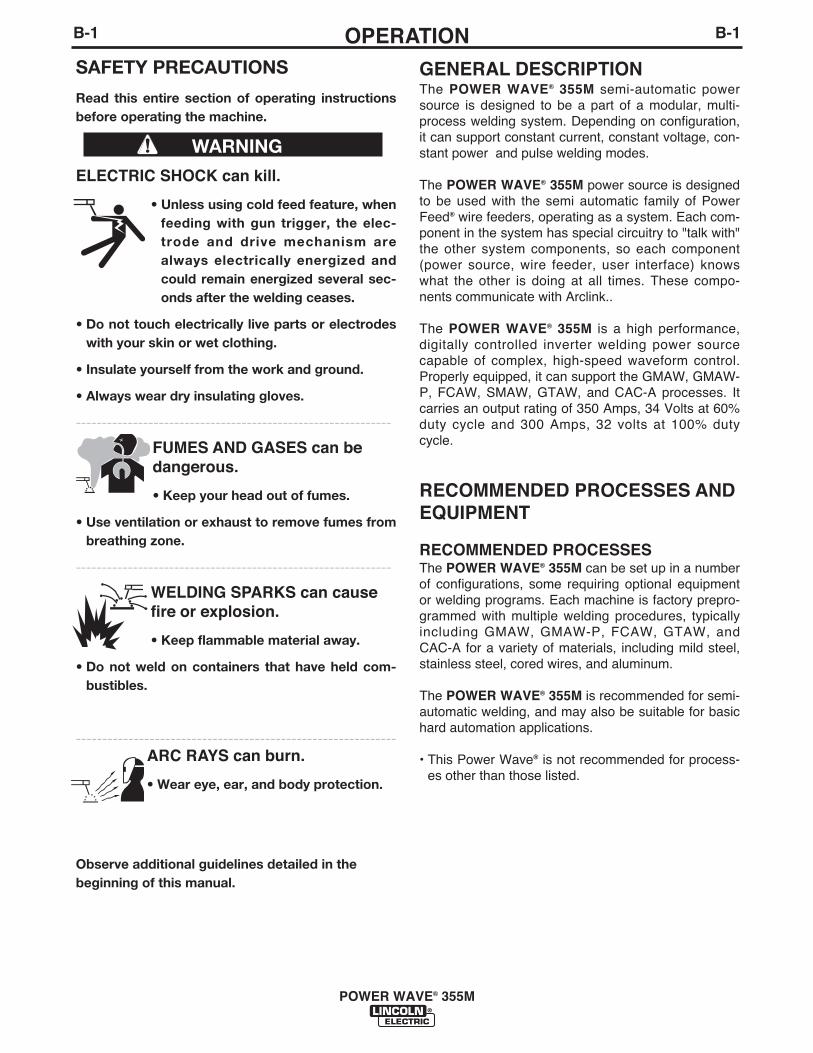
SAFETY PRECAUTIONS
Read this entire section of operating instructionsbefore operating the machine.
ELECTRIC SHOCK can kill.
• Unless using cold feed feature, whenfeeding with gun trigger, the elec-trode and drive mechanism arealways electrically energized andcould remain energized several sec-onds after the welding ceases.
• Do not touch electrically live parts or electrodeswith your skin or wet clothing.
• Insulate yourself from the work and ground.
• Always wear dry insulating gloves.
-------------------------------------------------------------
FUMES AND GASES can bedangerous.
• Keep your head out of fumes.
• Use ventilation or exhaust to remove fumes frombreathing zone.
-------------------------------------------------------------
WELDING SPARKS can causefire or explosion.
• Keep flammable material away.
• Do not weld on containers that have held com-bustibles.
-------------------------------------------------------------ARC RAYS can burn.
• Wear eye, ear, and body protection.
Observe additional guidelines detailed in thebeginning of this manual.
WARNING

5. Internal POWER CIRCUIT BREAKER: Protects 115volt AC circuit.
6. LEAD CONNECTOR (SENSE LEAD)
7. DIAGNOSTIC CONNECTOR (RS-232)
8. WIRE FEEDER RECEPTACLE (5-PIN)
9. NEGATIVE TWIST- MATE TERMINAL
10. POSITIVE TWIST- MATE TERMINAL
FIGURE B.1
10
46
1
32
5
7
8
9
CASE FRONT LAYOUTPOWER WAVE® 355M
POWER WAVE® 355M – Semi-Automatic Operation
POWER WAVE® 355M can only be used with ArcLinkcompatible Power Feed® M semi-automatic wirefeeders. In addition, the Power Feed® semi-automaticwire feeders may require optional equipment toaccess certain weld modes in the Power Wave®. Othermodels of Lincoln feeders, or any models of non-Lincoln wire feeders, cannot be used.
All welding programs and procedures are selectedthrough the Power Feed® M semi-automatic user inter-face
REQUIRED EQUIPMENTAny ArcLink compatible semi-automatic wire feedingequipment. Specifically, the semi-automatic PowerFeed® M family.
LIMITATIONS• Only ArcLink compatible Power Feed® M semi-
automatic wire feeders and users interfaces may beused. Other Lincoln wire feeders or non-Lincoln wirefeeders cannot be used.
• POWER WAVE® 355M Output LimitationsThe POWER WAVE® 355M will support maximumaverage output current of 350 Amps @ 60% dutycycle.
DUTY CYCLE AND TIME PERIODThe duty cycle is based upon a ten minute period. A60% duty cycle represents 6 minutes of welding and 4minutes of idling in a ten minute period.
CASE FRONT CONTROLSAll operator controls are located on the case front ofthe Power Wave®. (See Figure B.1)
1. POWER SWITCH: Controls input power to thePower Wave®.
2. STATUS LIGHT: A two color light that indicatessystem errors. Normal operation is a steady greenl ight. Error cond it ions are ind icated, perTroubleshooting E Section in this Manual.
NOTE: The POWER WAVE® 355M status light willflash green, and sometimes red and green, for up toone minute when the machine is first turned on. Thisis a normal situation as the machine goes through aself test at power up.
B-2OPERATIONB-2
POWER WAVE® 355M
3. HIGH TEMPERATURE LIGHT (thermal overload):A yellow light that comes on when an over temper-ature situation occurs. Output is disabled and thefan continues to run, until the machine cools down.When cool, the l ight goes out and output isenabled.
4. CB1 WIRE FEEDER CIRCUIT BREAKER :Protects 40 volt DC wire feeder power supply.

WELDING ADJUSTMENTS
All adjustments are made on the system componentknown as the User Interface (Control Box), which con-tains the switches, knobs, and digital displays neces-sary to control both the Power Wave® and a PowerFeed® wire feeder. Typically, the Control Box is sup-plied as part of the wire feeder. It can be mounteddirectly on the wire feeder itself, or mounted separate-ly, as might be done in a welding boom installation.
Because the Control Box can be configured with manydifferent options, your system may not have all of thefollowing adjustments. Regardless of availability, allcontrols are described below. For further information,consult the Power Feed® wire feeder instruction manu-al.
• WFS / AMPS:In synergic weld ing modes (synergic CV, pulseGMAW) WFS (wire feed speed) is the dominant con-trol parameter, controlling all other variables. The useradjusts WFS according to factors such as weld size,penetration requirements, heat input, etc. The PowerWave® then uses the WFS setting to adjust its outputcharacteristics (output voltage, output current) accord-ing to pre-programmed settings contained in thePower Wave®.
In non-synergic modes, the WFS control behavesmore like a conventional CV power source whereWFS and voltage are independent adjustments.Therefore to maintain the arc characteristics, the oper-ator must adjust the voltage to compensate for anychanges made to the WFS.
In constant current modes (stick, TIG) this controladjusts the output current, in amps.
• VOLTS / TRIM:In constant voltage modes (synergic CV, standardCV) the control adjusts the welding voltage.
In pulse synergic welding modes (pulse GMAW only)the user can change the Trim setting to adjust the arclength. It is adjustable from 0.500 to 1.500. A Trim set-ting of 1.000 is a good starting point for most condi-tions.
• WELDING MODEMay be selected by name (CV/MIG, CC/Stick Crisp,Gouge, etc.) or by a mode number (10, 24, 71, etc.)depending on the Control Box options. Selecting awelding mode determines the output characteristics ofthe Power Wave® power source. For a more completedescription of the welding modes available in thePower Wave®, see the explanation following.
B-3OPERATION
POWER WAVE® 355M
B-3
NOMINAL PROCEDURESThe Power Wave® is des igned to operate w i th3/4"(7.62) electrode st ick-out for CV and Pulseprocesses.
FRINGE PROCEDURESExcessively short or long electrode stick-outs mayfunction only on a limited basis, if at all.
MAKING A WELD
The serviceability of a product or structure utiliz-ing the welding programs is and must be the soleresponsibility of the builder/user. Many variablesbeyond the control of The Lincoln ElectricCompany affect the results obtained in applyingthese programs. These variables include, but arenot limited to, welding procedure, plate chemistryand temperature, weldment design, fabricationmethods and service requirements. The availablerange of a welding program may not be suitablefor all applications, and the build/user is and mustbe solely responsible for welding program selec-tion.------------------------------------------------------------------------
The steps for operating the Power Wave® will varydepending upon the options installed in the user inter-face (control box) of the welding system. The flexibilityof the Power Wave® system lets the user customizeoperation for the best performance.
First, consider the desired welding process and thepart to be welded. Choose an electrode material,diameter, shielding gas and process (GMAW, GMAW-P, etc.)
Second, find the program in the welding software thatbest matches the desired welding process. The stan-dard software shipped with the Power Waves® encom-passes a wide range of common processes and willmeet most needs. If a special welding program isdesired, contact the local Lincoln Electric sales repre-sentative.
To make a weld, the Power Wave® needs to know thedesired welding parameters. The Power Feed® (PF)family of feeders communicate settings to the PowerWave through control cable connection. Arc length,wire feed speed, arc control, etc. are all communicat-ed digitally via the control cable.
WARNING
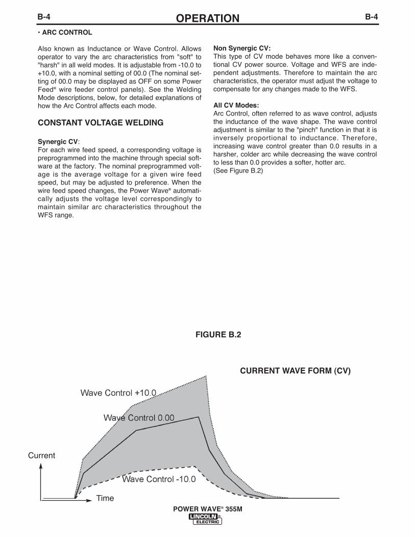
Non Synergic CV:This type of CV mode behaves more like a conven-tional CV power source. Voltage and WFS are inde-pendent adjustments. Therefore to maintain the arccharacteristics, the operator must adjust the voltage tocompensate for any changes made to the WFS.
All CV Modes:Arc Control, often referred to as wave control, adjuststhe inductance of the wave shape. The wave controladjustment is similar to the "pinch" function in that it isinversely proportional to inductance. Therefore,increasing wave control greater than 0.0 results in aharsher, colder arc while decreasing the wave controlto less than 0.0 provides a softer, hotter arc.(See Figure B.2)
FIGURE B.2
Current
Time
CURRENT WAVE FORM (CV)
B-4OPERATIONB-4
• ARC CONTROL
Also known as Inductance or Wave Control. Allowsoperator to vary the arc characteristics from "soft" to"harsh" in all weld modes. It is adjustable from -10.0 to+10.0, with a nominal setting of 00.0 (The nominal set-ting of 00.0 may be displayed as OFF on some PowerFeed® wire feeder control panels). See the WeldingMode descriptions, below, for detailed explanations ofhow the Arc Control affects each mode.
CONSTANT VOLTAGE WELDING
Synergic CV:For each wire feed speed, a corresponding voltage ispreprogrammed into the machine through special soft-ware at the factory. The nominal preprogrammed volt-age is the average voltage for a given wire feedspeed, but may be adjusted to preference. When thewire feed speed changes, the Power Wave® automati-cally adjusts the voltage level correspondingly tomaintain similar arc characteristics throughout theWFS range.
POWER WAVE® 355M

PULSE-ON-PULSE® (GMAW-PP)Pulse on Pulse® is a Lincoln process specificallydesigned for use in welding relatively thin, less than1/4"(6.4mm) thick aluminum (See Table B.3). It givesweld beads with very consistent uniform ripple.
In Pulse on Pulse® modes, two distinct pulse types areused, instead of the single pulse type normally used inGMAW-P. A number of high energy pulses are usedto obtain spray transfer and transfer metal across thearc. Such pulses are shown in Figure B.4. After anumber "N" of such pulses, depending on the wirefeed speed used, an identical number "N" of low ener-gy pulses are performed. These low energy pulses,shown in Figure B.4, do not transfer any filler metalacross the arc and help to cool the arc and keep theheat input low.
The Peak Current, Background Current, andFrequency are identical for the high energy and lowenergy pulses. In addition to cooling the weld down,the major effect of the low energy pulses is that theyform a weld ripple. Since they occur at very regulartime intervals, the weld bead obtained is very uniformwith a very consistent ripple pattern. In fact, the beadhas its best appearance if no oscillation of the weldinggun ("whipping") is used.(See Figure B.5)
When Arc Control is used in the Pulse on Pulse®
modes, it does the same things it does in the otherpulsed modes: decreasing the Arc Control decreasesthe droplet transfer and weld depos it ion rate.Increasing the Arc Control increases the droplet trans-fer and weld deposition rate. Since Arc Control variesweld droplet transfer rate, the Arc Control can be usedto vary the ripple spacing in the weld bead.
PEAK AMPS
BACKGROUND AMPS
TIME
HIGH HEATPULSES
LOW HEATPULSES
"N" PULSES "N" PULSES
FIGURE B.4
FIGURE B.5
B-5OPERATIONB-5
POWER WAVE® 355M
PULSE WELDING
Pulse welding procedures are set by controlling anoverall "arc length" variable. When pulse welding, thearc voltage is highly dependent upon the waveform.The peak current, back ground current, rise time, falltime and pulse frequency all affect the voltage. Theexact voltage for a given wire feed speed can only bepredicted when all the pulsing waveform parametersare known. Using a preset voltage becomes impracti-cal, and instead the arc length is set by adjusting"trim".
Trim adjusts the arc length and ranges from 0.50 to1.50, with a nominal value of 1.00. Trim values greaterthan 1.00 increase the arc length, while values lessthan 1.00 decrease the arc length.
All pulse welding programs are synergic. As the wirefeed speed is adjusted, the Power Wave® will auto-matically recalculate the waveform parameters tomaintain similar arc properties.
The Power Wave® utilizes "adaptive control" to com-pensate for changes in electrical stick out while weld-ing. (Contact to Work Distance is the distance fromthe contact tip to the work piece.) The Power Wave®
wave forms are optimized for a 0.75" (19mm) stick-out. The adaptive behavior supports a range of stick-outs from 0.50" (13mm) to 1.25" (32mm). At very lowor high wire feed speeds, the adaptive range may beless due to reaching physical limitations of the weldingprocess.
Arc Control, often referred to as wave control, in pulseprograms usually adjusts the focus or shape of thearc. Wave control values greater than 0.0 increase thepulse frequency while decreasing the background cur-rent, resulting in a tight, stiff arc best for high speedsheet metal welding. Wave control values less than0.0 decrease the pulse frequency while increasing thebackground current, for a soft arc good for out-of-posi-tion welding.
FIGURE B.3
Current
Time
CURRENT WAVE FORM (PULSE)

B-6OPERATIONB-6
POWER WAVE® 355M
BENEFITS OF PULSE ON PULSE® FROMLINCOLN ELECTRIC
• Excellent appearance of the weld bead• Improved cleaning action• Reduced porosityTable B.2 shows WFS and Trim settings for commonaluminum types and wire sizes when welding withPulse-on-Pulse®. The welds made to obtain the valuesin the table were fillet welds in the flat position. Thevalues in the table can be helpful as a starting point toestablish a welding procedure. From there, adjust-ments need to be made to set the proper procedurefor each specific application (out-of-position, othertypes of joints, etc.).The comments on Table B.3 show values of WFSbelow which it is not recommended to weld. The rea-son is, that below these values the weld transfer willchange from a spray arc to a short-arc, which is notadvisable when welding aluminum.
TIG GTAWThe TIG mode features continuous control from 5 to425 amps. The TIG mode can be run in either theTouch Start TIG or Scratch start mode.
The Arc Control level selects the starting mode.
Between –10 and 0, the Touch Start TIG mode isselected. The OCV is controlled below 10V and theshort circuit "TIG touch" current is maintained atapproximately 25 amps, independent of the presetcurrent. When the tungsten is lifted, an arc is initiatedand the output is regulated at the preset value. A set-ting of 0, results in the most positive arc initiation. Asetting of -10 reduces hot start. Procedure to start theweld, and from there, to ramp to the welding procedure overa specified amount of time. Typically starting procedure on ahigher “+” setting is known as a “Hot Start”. Setting a start-ing procedure on a lower setting is known as a “Cold Start”.
Between 0 and 10, the Scratch starting TIG mode isselected. In this range, the OCV of the machine iscontrolled between 50 and 70 volts
Aluminum 4043 Aluminum 4043 Aluminum 5356 Aluminum 5356
100% Ar. 100% Ar. 100% Ar. 100% Ar.
E4043 E4043 E5356 E5356
0.035 3/64 0.035 3/64
98 99 101 102
14 ga. 250 / 1.0 200 / 1.0 230 / 1.0 225 / 1.0
10 ga. 400 /1.0 280 / 1.0 425 / 1.0 400 / 1.0
3/16 550 / 1.0 340 / 1.0 670 / 1.0 500 / 1.0
1/4 600 / 1.0 400 / 1.0 700 / 1.0 550 / 0.9
WFS
/ TR
IM
MA
TER
IAL
THIC
KN
ESS
MATERIAL
GAS
WIRE
WIRE SIZE
WELD MODE
Not Recommended
below 200 WFSCOMMENTS Not Recommended
below 200 WFS
Not Recommended
below 100 WFS
Not Recommended
below 200 WFS
WELDING PROCEDURES FOR PULSE-ON-PULSE® (TABLE B.2)
(See Figure B.3)SMAWIn SMAW (STICK mode), arc control adjusts the arcforce. It can be set to the lower range for a soft andless penetrating arc characteristic (negative numericvalues) or to the higher range (positive numeric val-ues) for a crisp and more penetrating arc. Normally,when welding with cellulosic types of electrodes(E6010, E7010, E6011), a higher energy arc isrequired to maintain arc stability. This is usually indi-cated when the electrode sticks to the work-piece orwhen the arc pops-out during manipulative technique.For low hydrogen types of electrodes (E7018, E8018,E9018, etc.) a softer arc is usually desirable and thelower end of the Arc Control suits these types of elec-trodes. In either case the arc control is available toincrease or decrease the energy level delivered to thearc.
ARC GOUGINGGouging is basically removing metal to form a bevel orgroove in a piece of steel with controlled forced airand a carbon rod.
The common procedures for Arc Gouging metal are:
• Removing poor welds from a weldment so that newwelds can be made.
• Creating a welding groove or grooves in two piecesof steel butted together. (See Example below)
Mode 9 in the POWER WAVE® 355M is specifically forgouging. Gouging can also be done in the stick softand crisp modes. Setting the output of the Stick Softmode to 425 amps will enable the arc-gouging mode.The actual output current will depend on the size ofcarbon used. The recommended maximum size car-bon is 5/16".
STEEL BUTTED TOGTHER
WELD GROOVES CREATED BY ARC GOUGING

B-7OPERATIONB-7
POWER WAVE® 355M
POWER MODE®
The Power Mode® process was developed by Lincolnto maintain a stable and smooth arc at low proceduresettings which are needed to weld thin metal withoutpop-outs or burning-through. For aluminum welding, itprovides excellent control and the ability to maintainconstant arc length. This results in improved weldingperformance in two primary types of applications.
• Short Arc MIG at low procedure settings.
• Aluminum MIG welding.
Power Mode® is a method of high speed regulation ofthe output power whenever an arc is established. Itprovides a fast response to changes in the arc. Thehigher the Power Mode® Setting, the longer the arc. Ifa welding procedure is not established, the best wayto determine the Power Mode® Setting is by experi-mentation until the desired output result is estab-lished.
In the Power Mode® two variables need to be set:
• Wire Feed Speed
• Power Mode® Trim
Setting up a Power Mode® procedure is similar to set-ting a CV MIG procedure. Select a shielding gasappropriate for a short arc process.
• For steel, use 75/25 Ar/CO2 shield gas.
• For stainless, select a Helium blend Tri-Mix.
• For aluminum, use 100% Ar.
Start by setting the wire feed speed based upon mate-rial thickness and appropriate travel speed. Thenadjust the Volts/Trim knob as follows:
• For steel, listen for the traditional “frying egg”sound of a good short-arc MIG procedure to knowyou have the process set correctly.
• For aluminum, simply adjust the Volts/Trim knobuntil the desired arc length is obtained.
Note the Volts/Trim display is simply a relative numberand DOES NOT correspond to voltage.
Some procedure recommendations appear in TableB.3.
below 400 WFS
below 400 WFS
Recommended Welding Procedures for Power Mode® - Table B.3

C-1ACCESSORIESC-1
OPTIONAL EQUIPMENT
FACTORY INSTALLED
None Available.
FIELD INSTALLED K940-Work Voltage Sense Lead KitK1764-1-Undercarriage*K1838-1-Valet Style UndercarriageK1796-Coaxial Welding Cable-(Requires Adapter K2176-1)K2176-1 Twist-mate to Lug Adapters* Dual Cylinder Kit for K1764-1 is K1702-1
Welding Cable Connectors:K852-70 1/0-2/0 CABLEK852-95 2/0-3/0 CABLE
COMPATIBLE LINCOLN EQUIPMENT
Any ArcLink compatible wire feeding equipment.
POWER WAVE® 355M
D-1MAINTENANCED-1
POWER WAVE® 355M
SAFETY PRECAUTIONS
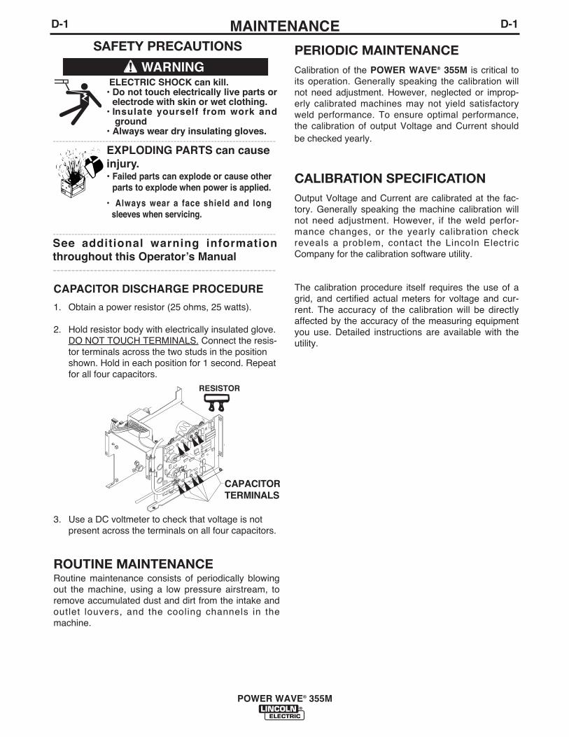
CAPACITOR DISCHARGE PROCEDURE
1. Obtain a power resistor (25 ohms, 25 watts).
2. Hold resistor body with electrically insulated glove.DO NOT TOUCH TERMINALS. Connect the resis-tor terminals across the two studs in the positionshown. Hold in each position for 1 second. Repeatfor all four capacitors.
3. Use a DC voltmeter to check that voltage is notpresent across the terminals on all four capacitors.
ROUTINE MAINTENANCERoutine maintenance consists of periodically blowingout the machine, using a low pressure airstream, toremove accumulated dust and dirt from the intake andoutlet louvers, and the cool ing channels in themachine.
CAPACITORTERMINALS
RESISTOR
PERIODIC MAINTENANCECalibration of the POWER WAVE® 355M is critical toits operation. Generally speaking the calibration willnot need adjustment. However, neglected or improp-erly calibrated machines may not yield satisfactoryweld performance. To ensure optimal performance,the calibration of output Voltage and Current shouldbe checked yearly.
CALIBRATION SPECIFICATIONOutput Voltage and Current are calibrated at the fac-tory. Generally speaking the machine calibration willnot need adjustment. However, if the weld perfor-mance changes, or the yearly calibration checkreveals a prob lem, contact the Lincoln E lectricCompany for the calibration software utility.
The calibration procedure itself requires the use of agrid, and certified actual meters for voltage and cur-rent. The accuracy of the calibration will be directlyaffected by the accuracy of the measuring equipmentyou use. Detailed instructions are available with theutility.
ELECTRIC SHOCK can kill.• Do not touch electrically live parts or
electrode with skin or wet clothing.• Insulate yourself from work and
ground• Always wear dry insulating gloves.
------------------------------------------------------------------------EXPLODING PARTS can causeinjury.• Failed parts can explode or cause other
parts to explode when power is applied.
• Always wear a face shield and longsleeves when servicing.
------------------------------------------------------------------------See additional warning informationthroughout this Operatorʼs Manual ------------------------------------------------------------
WARNING

E-1TROUBLESHOOTINGE-1
POWER WAVE® 355M
If for any reason you do not understand the test procedures or are unable to perform the tests/repairs safely, contact yourLocal Lincoln Authorized Field Service Facility for technical troubleshooting assistance before you proceed.
CAUTION
This Troubleshooting Guide is provided to help youlocate and repair possible machine malfunctions.Simply follow the three-step procedure listed below.
Step 1. LOCATE PROBLEM (SYMPTOM).Look under the column labeled “PROBLEM (SYMP-TOMS)”. This column describes possible symptomsthat the machine may exhibit. Find the listing thatbest describes the symptom that the machine isexhibiting.
Step 2. POSSIBLE CAUSE.The second column labeled “POSSIBLE CAUSE” liststhe obvious external possibilities that may contributeto the machine symptom.
Step 3. RECOMMENDED COURSE OF ACTIONThis column provides a course of action for thePossible Cause, generally it states to contact yourlocal Lincoln Authorized Field Service Facility.
If you do not understand or are unable to perform theRecommended Course of Action safely, contact yourlocal Lincoln Authorized Field Service Facility.
HOW TO USE TROUBLESHOOTING GUIDE
Service and Repair should only be performed by Lincoln Electric Factory Trained Personnel.Unauthorized repairs performed on this equipment may result in danger to the technician andmachine operator and will invalidate your factory warranty. For your safety and to avoid ElectricalShock, please observe all safety notes and precautions detailed throughout this manual.
__________________________________________________________________________
WARNING

E-2TROUBLESHOOTINGE-2
POWER WAVE® 355M
USING THE STATUS LED TOTROUBLESHOOT SYSTEM PROBLEMS
The Power Wave® / Power Feed® are best diagnosedas a system. Each component (power source, userinterface, and feedhead) has a status light, and whena problem occurs it is important to note the conditionof each. In addition, errors displayed on the user inter-face in most cases indicate only that a problem existsin the power source, not what the problem may be.Therefore, prior to cycling power to the system,check the power source status light for errorsequences as noted below. This is especiallyimportant if the user interface displays "Err 006"or "Err 100" .
Included in this section is information about the powersource Status LED, and some basic troubleshootingcharts for both machine and weld performance.
The STATUS LIGHT is a two color light that indicatessystem errors. Normal operation is a steady greenlight. Error conditions are indicated in the followingchart.
NOTE: The POWER WAVE® 355M status light willflash green, and sometimes red and green, for up toone minute when the machine is first turned on. Thisis a normal situation as the machine goes through aself test at power up.
LIGHT CONDITIONStatus LED is solid green (no blinking).
Status LED is blinking green.
Status LED is blinking red and green.
Status LED is solid red (no blinking).
Status LED is blinking red.
MEANING1. System OK. Power source communicating normally
with wire feeder and its components, if other fea-tures and components show they are powered up.
2. Occurs during a reset, and indicates the POWERWAVE® 355M is mapping (identifying) each compo-nent in the system. Normal for first 1-10 secondsafter power is turned on, or if the system configura-tion is changed during operation.
3. Non-recoverable system fault. If the PS Status lightis flashing any combination of red and green, errorsare present in the POWER WAVE® 355M. Read theerror code before the machine is turned off.
Error Code interpretation through the Status light isdetailed in the Service Manual. Individual code digitsare flashed in red with a long pause between digits. Ifmore than one code is present, the codes will beseparated by a green light.
To clear the error, turn power source off, and backon to reset.
Non recoverable hardware fault. Generally indicatesnothing is connected to the POWER WAVE® 355Mwire feeder receptacle. See Trouble Shooting Section.
Not applicable.

E-3TROUBLESHOOTINGE-3
POWER WAVE® 355M
Observe all Safety Guidelines detailed throughout this manual
If for any reason you do not understand the test procedures or are unable to perform the tests/repairs safely, contact yourLocal Lincoln Authorized Field Service Facility for technical troubleshooting assistance before you proceed.
CAUTION
ERROR CODES FOR THE POWERWAVEThe following is a list of possible error codes that the POWER WAVE® 355M can output via the status light (see"Troubleshooting the Power Wave / Power Feed System Using the Status LED." If connected to a PF-10/11these error codes will generally be accompanied by an "Err 006" or "Err 100" on the user interface display.
Error Code #11 CAN communication bus off.12 User Interface time out error.
21 Unprogrammed Weld Mode.
22 Empty Weld Table.
23 Weld Table checksum error.
31 Primary overcurrent error.
32 Capacitor "A" under voltage
33 Capacitor "B" under voltage
34 Capacitor "A" over voltage
35 Capacitor "B" over voltage
36 Thermal error
37 Soft start error
41 Secondary overcurrent error
43 Capacitor delta error
Other See Power Wave® Diagnostic Software.The Service Navigator has additional and later Error Codes listed inthe diagnostic Utility Software.Also similar information can be found on Web site at www.powerwavesoftware.com.
IndicationProbably due to excessive number of communication errors.UI is no longer responding to the Power Source. The most likelycause is a fault/bad connection in the communication leads or con-trol cable.
Contact the Service Department for instructions on reloading theWelding Software.Contact the Service Department for instructions on reloading theWelding Software.Contact the Service Department for instructions on reloading theWelding Software.Excessive Primary current present. May be related to a short in themain transformer or output rectifier.Low voltage on the main capacitors. May be caused by improperinput configuration. When accompanied by an overvoltage error on the same side, itindicates no capacitor voltage present on that side, and is usuallythe result of an open or short in the primary side of the machine.Excess voltage on the main capacitors. May be caused by improp-er input configuration.
When accompanied by an under voltage error on the same side, itindicates no capacitor voltage present on that side, and is usuallythe result of an open or short in the primary side of the machine.
Indicates over temperature. Usually accompanied by Thermal LED.Check fan operation. Be sure process does not exceed duty cyclelimit of the machine.
Capacitor precharge failed. Usually accompanied by codes 32-35.The secondary (weld) current limit has been exceeded. When thisoccurs the machine output will phase back to 100 amps, typicallyresulting in a condition referred to as "noodle welding"
NOTE: The secondary limit is 570 amps for the standard stud, and325 amps for all single phase operation.
The maximum voltage difference between the main capacitors hasbeen exceeded. May be accompanied by errors 32-35.
Error codes that contain three or four digits are defined as fatalerrors. These codes generally indicate internal errors on theControl Board. If cycling the input power on the machine does notclear the error, try reloading the operating system. If this fails,replace the control board.
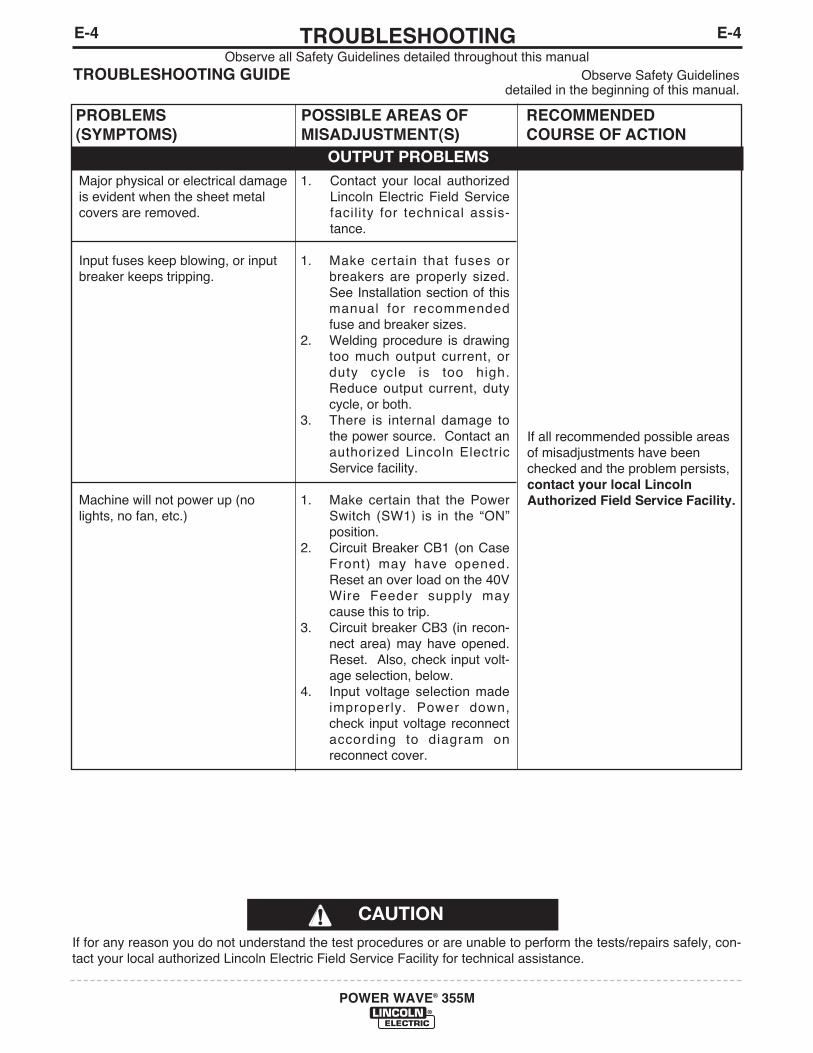
E-4TROUBLESHOOTINGE-4
POWER WAVE® 355M
Observe all Safety Guidelines detailed throughout this manualTROUBLESHOOTING GUIDE Observe Safety Guidelines
detailed in the beginning of this manual.
CAUTIONIf for any reason you do not understand the test procedures or are unable to perform the tests/repairs safely, con-tact your local authorized Lincoln Electric Field Service Facility for technical assistance.
PROBLEMS(SYMPTOMS)
POSSIBLE AREAS OFMISADJUSTMENT(S)
RECOMMENDEDCOURSE OF ACTION
OUTPUT PROBLEMSMajor physical or electrical damageis evident when the sheet metalcovers are removed.
Input fuses keep blowing, or inputbreaker keeps tripping.
Machine will not power up (nolights, no fan, etc.)
1. Contact your local authorizedLincoln Electric Field Servicefaci l ity for techn ical ass is-tance.
1. Make certa in that fuses orbreakers are properly sized.See Installation section of thismanual for recommendedfuse and breaker sizes.
2. Welding procedure is drawingtoo much output current, orduty cyc le is too high.Reduce output current, dutycycle, or both.
3. There is internal damage tothe power source. Contact anauthorized Lincoln E lectricService facility.
1. Make certain that the PowerSwitch (SW1) is in the “ON”position.
2. Circuit Breaker CB1 (on CaseFront) may have opened.Reset an over load on the 40VWire Feeder supply maycause this to trip.
3. Circuit breaker CB3 (in recon-nect area) may have opened.Reset. Also, check input volt-age selection, below.
4. Input voltage selection madeimproper ly. Power down,check input voltage reconnectaccord ing to d iagram onreconnect cover.
If all recommended possible areasof misadjustments have beenchecked and the problem persists,contact your local LincolnAuthorized Field Service Facility.

E-5TROUBLESHOOTINGE-5
POWER WAVE® 355M
Observe all Safety Guidelines detailed throughout this manualTROUBLESHOOTING GUIDE Observe Safety Guidelines
detailed in the beginning of this manual.
CAUTIONIf for any reason you do not understand the test procedures or are unable to perform the tests/repairs safely, con-tact your local authorized Lincoln Electric Field Service Facility for technical assistance.
PROBLEMS(SYMPTOMS)
POSSIBLE AREAS OFMISADJUSTMENT(S)
RECOMMENDEDCOURSE OF ACTION
OUTPUT PROBLEMSThermal LED is lit.
Machine wonʼt weld, canʼt get anyoutput.
1. Fan thermostat has opened.Check for proper fan operation.(Fan should run whenever outputpower is on.) Check for materialblocking intake or exhaust louvers,or for excessive dirt clogging cool-ing channels in machine. Blow airin rear louvers to remove d i rtaround the fan.
2. Secondary rectifier or Choke ther-mostat has opened. After machinehas cooled, reduce load, dutycycle, or both. Check for materialblocking intake or exhaust louvers.
3. DC Bus PC board thermostat hasopened check for excessive loadon 40VDC supply.
1. Input voltage is too low or toohigh. Make certain that input volt-age is proper, according to theRating Plate located on the rear ofthe machine.
2. If the Thermal LED is also lit, see“Yellow Thermal LED is Lit” sec-tion.
3. Primary current limit has beenexceeded. Possible short in outputcircuit. Turn machine off. Removeall loads from the output of themachine. Turn back on. If condi-tion persists, turn power off, andcontact an authorized LincolnElectric Field Service facility.
4. This prob lem w i l l normally beaccompanied by an error code.Error codes are displayed as aseries of red and green flashes bythe status l ight. See"Troub leshoot ing the PowerWave® / Power Feed® SystemUsing the Status LED" section ofthis text.
If all recommended possible areasof misadjustments have beenchecked and the problem persists,contact your local LincolnAuthorized Field Service Facility.

E-6TROUBLESHOOTINGE-6
POWER WAVE® 355M
Observe all Safety Guidelines detailed throughout this manualTROUBLESHOOTING GUIDE Observe Safety Guidelines
detailed in the beginning of this manual.
CAUTIONIf for any reason you do not understand the test procedures or are unable to perform the tests/repairs safely, con-tact your local authorized Lincoln Electric Field Service Facility for technical assistance.
PROBLEMS(SYMPTOMS)
POSSIBLE AREAS OFMISADJUSTMENT(S)
RECOMMENDEDCOURSE OF ACTION
OUTPUT PROBLEMSMachine often “noodle welds” (out-put is limited to approximately 100amps) when running a particularprocedure, especially a procedurewith high WFS.
Machine wonʼt produce full output.
1.Secondary current limit has beenexceeded, and the machine hasphased back to protect itself.
2. Adjust procedure or reduce loadto lower current draw from themachine.
1. Input voltage may be too low,limiting output capability of thepower source. Make certain thatthe input voltage is proper,according to the Rating Platelocated on the rear of themachine.
2. Secondary current or voltage notbe properly calibrated. Checkvalues displayed on the PowerFeed 10/11 verses readings onan external meter.
If all recommended possible areasof misadjustments have beenchecked and the problem persists,contact your local LincolnAuthorized Field Service Facility.
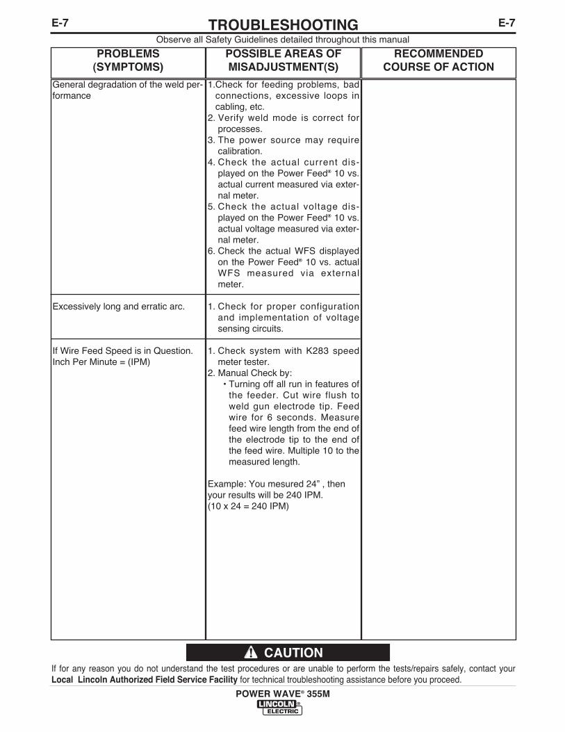
E-7TROUBLESHOOTINGE-7
POWER WAVE® 355M
Observe all Safety Guidelines detailed throughout this manual
If for any reason you do not understand the test procedures or are unable to perform the tests/repairs safely, contact yourLocal Lincoln Authorized Field Service Facility for technical troubleshooting assistance before you proceed.
CAUTION
PROBLEMS(SYMPTOMS)
POSSIBLE AREAS OFMISADJUSTMENT(S)
RECOMMENDEDCOURSE OF ACTION
General degradation of the weld per-formance
Excessively long and erratic arc.
If Wire Feed Speed is in Question.Inch Per Minute = (IPM)
1.Check for feeding problems, badconnections, excessive loops incabling, etc.
2. Verify weld mode is correct forprocesses.
3. The power source may requirecalibration.
4. Check the ac tual current d is-played on the Power Feed® 10 vs.actual current measured via exter-nal meter.
5. Check the actual voltage d is-played on the Power Feed® 10 vs.actual voltage measured via exter-nal meter.
6. Check the actual WFS displayedon the Power Feed® 10 vs. actualWFS measured v ia externalmeter.
1. Check for proper configurationand implementation of voltagesensing circuits.
1. Check system with K283 speedmeter tester.
2. Manual Check by:• Turning off all run in features of
the feeder. Cut wire flush toweld gun electrode tip. Feedwire for 6 seconds. Measurefeed wire length from the end ofthe electrode tip to the end ofthe feed wire. Multiple 10 to themeasured length.
Example: You mesured 24” , then your results will be 240 IPM. (10 x 24 = 240 IPM)
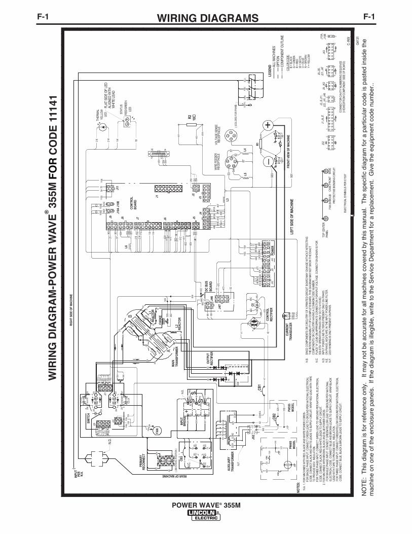
F-1WIRING DIAGRAMSF-1
POWER WAVE® 355M
NOTE
: Thi
s di
agram
is for re
fere
nce
only
. It
may
not
be
accura
te for
all m
achi
nes co
vere
d by
this
man
ual.
The
speci
fic diagr
am for
a partic
ular
cod
e is
pas
ted in
side
the
machi
ne o
n on
e of
the
encl
osur
e pa
nels
. If
the
diagram
is il
legibl
e, writ
e to
the
Ser
vice
Dep
artm
ent f
or a
rep
lacem
ent.
Giv
e th
e eq
uipm
ent c
ode
number.
.

F-2DIAGRAMSF-2
POWER WAVE® 355M
®
NOTE
: Thi
s di
agram
is for re
fere
nce
only
. It
may
not
be
accura
te for
all m
achi
nes co
vere
d by
this
man
ual.
The
speci
fic diagr
am for
a partic
ular
cod
e is
pas
ted in
side
the
machi
ne o
n on
e of
the
encl
osur
e pa
nels
. If
the
diagram
is il
legibl
e, writ
e to
the
Ser
vice
Dep
artm
ent f
or a
rep
lacem
ent.
Giv
e th
e eq
uipm
ent c
ode
number.
.
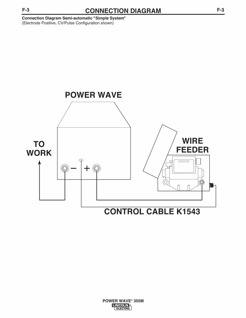
F-3CONNECTION DIAGRAMF-3
POWER WAVE® 355M
Connection Diagram Semi-automatic "Simple System"(Electrode Positive, CV/Pulse Configuration shown)
POWER WAVE
WIREFEEDER
CONTROL CABLE K1543
TOWORK
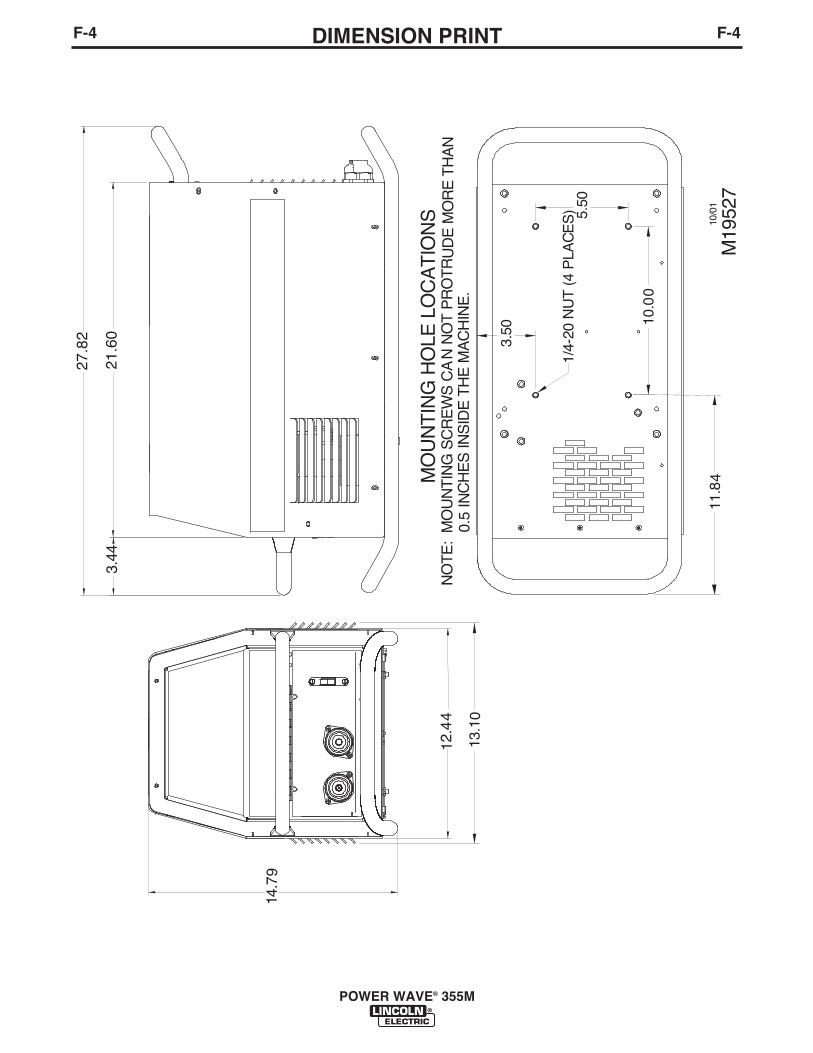
F-4DIMENSION PRINTF-4
POWER WAVE® 355M
1 4.7
9
12.4
4
3.44
21.6
0
27.8
2
5.50
10.0
0
MO
UN
TIN
G H
OLE
LO
CA
TIO
NS
M19
527
13.1
0
1/4-
20 N
UT
(4
PLA
CE
S)
NO
TE
: M
OU
NT
ING
SC
RE
WS
CA
10/0
1
N N
OT
PR
OT
RU
DE
MO
RE
TH
AN
0.
5 IN
CH
ES
INS
IDE
TH
E M
AC
HIN
E.
11.8
4
3.50

NOTES
POWER WAVE® 355M

NOTES
POWER WAVE® 355M

WARNING
AVISO DEPRECAUCION
ATTENTION
WARNUNG
ATENÇÃO
Spanish
French
German
Portuguese
Japanese
Chinese
Korean
Arabic
READ AND UNDERSTAND THE MANUFACTURER’S INSTRUCTION FOR THIS EQUIPMENT AND THE CONSUMABLES TO BEUSED AND FOLLOW YOUR EMPLOYER’S SAFETY PRACTICES.
SE RECOMIENDA LEER Y ENTENDER LAS INSTRUCCIONES DEL FABRICANTE PARA EL USO DE ESTE EQUIPO Y LOSCONSUMIBLES QUE VA A UTILIZAR, SIGA LAS MEDIDAS DE SEGURIDAD DE SU SUPERVISOR.
LISEZ ET COMPRENEZ LES INSTRUCTIONS DU FABRICANT EN CE QUI REGARDE CET EQUIPMENT ET LES PRODUITS AETRE EMPLOYES ET SUIVEZ LES PROCEDURES DE SECURITE DE VOTRE EMPLOYEUR.
LESEN SIE UND BEFOLGEN SIE DIE BETRIEBSANLEITUNG DER ANLAGE UND DEN ELEKTRODENEINSATZ DES HER-STELLERS. DIE UNFALLVERHÜTUNGSVORSCHRIFTEN DES ARBEITGEBERS SIND EBENFALLS ZU BEACHTEN.
� Do not touch electrically live parts orelectrode with skin or wet clothing.
� Insulate yourself from work andground.
� No toque las partes o los electrodosbajo carga con la piel o ropa moja-da.
� Aislese del trabajo y de la tierra.
� Ne laissez ni la peau ni des vête-ments mouillés entrer en contactavec des pièces sous tension.
� Isolez-vous du travail et de la terre.
� Berühren Sie keine stromführendenTeile oder Elektroden mit IhremKörper oder feuchter Kleidung!
� Isolieren Sie sich von denElektroden und dem Erdboden!
� Não toque partes elétricas e elec-trodos com a pele ou roupa molha-da.
� Isole-se da peça e terra.
� Keep flammable materials away.
� Mantenga el material combustiblefuera del área de trabajo.
� Gardez à l’écart de tout matérielinflammable.
� Entfernen Sie brennbarres Material!
� Mantenha inflamáveis bem guarda-dos.
� Wear eye, ear and body protection.
� Protéjase los ojos, los oídos y elcuerpo.
� Protégez vos yeux, vos oreilles etvotre corps.
� Tragen Sie Augen-, Ohren- und Kör-perschutz!
� Use proteção para a vista, ouvido ecorpo.
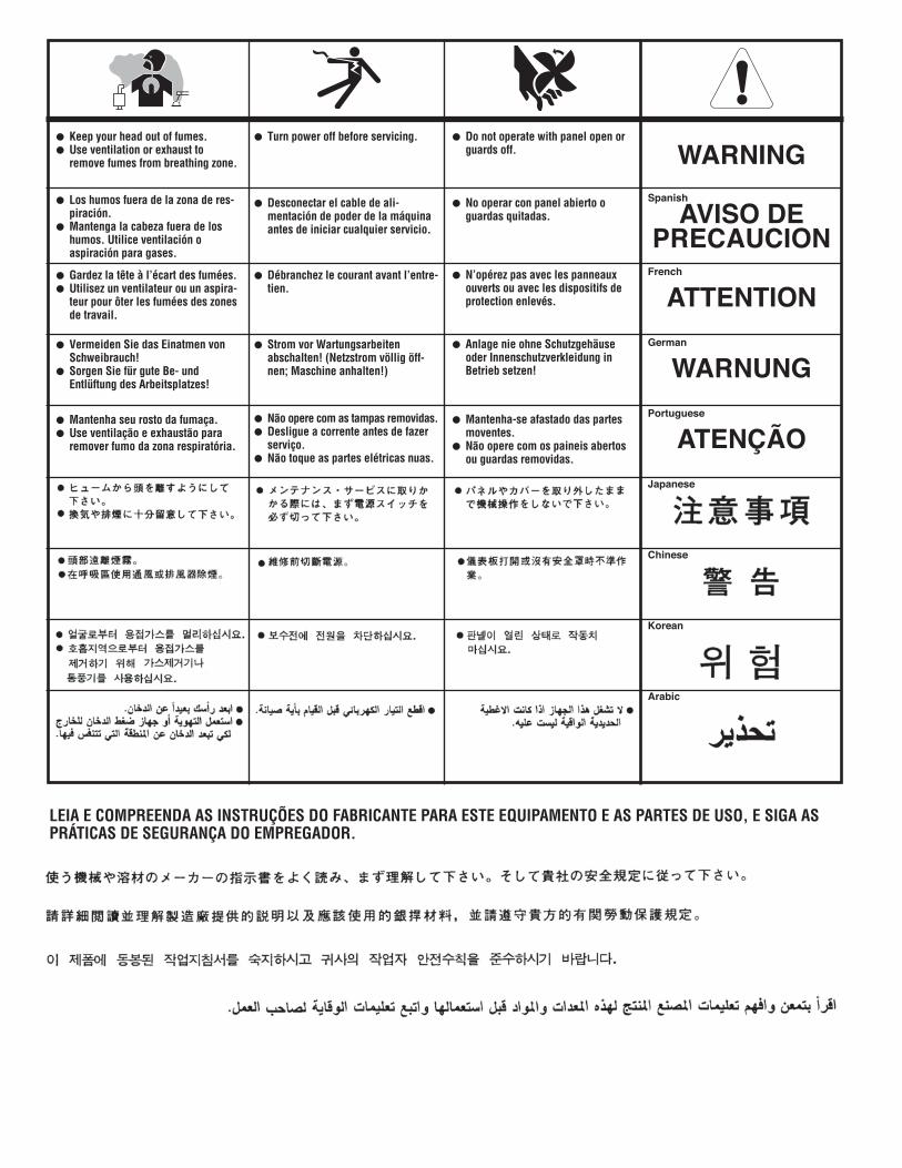
WARNING
AVISO DEPRECAUCION
ATTENTION
WARNUNG
ATENÇÃO
Spanish
French
German
Portuguese
Japanese
Chinese
Korean
Arabic
LEIA E COMPREENDA AS INSTRUÇÕES DO FABRICANTE PARA ESTE EQUIPAMENTO E AS PARTES DE USO, E SIGA ASPRÁTICAS DE SEGURANÇA DO EMPREGADOR.
� Keep your head out of fumes.� Use ventilation or exhaust to
remove fumes from breathing zone.
� Los humos fuera de la zona de res-piración.
� Mantenga la cabeza fuera de loshumos. Utilice ventilación oaspiración para gases.
� Gardez la tête à l’écart des fumées.� Utilisez un ventilateur ou un aspira-
teur pour ôter les fumées des zonesde travail.
� Vermeiden Sie das Einatmen vonSchweibrauch!
� Sorgen Sie für gute Be- undEntlüftung des Arbeitsplatzes!
� Mantenha seu rosto da fumaça.� Use ventilação e exhaustão para
remover fumo da zona respiratória.
� Turn power off before servicing.
� Desconectar el cable de ali-mentación de poder de la máquinaantes de iniciar cualquier servicio.
� Débranchez le courant avant l’entre-tien.
� Strom vor Wartungsarbeitenabschalten! (Netzstrom völlig öff-nen; Maschine anhalten!)
� Não opere com as tampas removidas.� Desligue a corrente antes de fazer
serviço.� Não toque as partes elétricas nuas.
� Do not operate with panel open orguards off.
� No operar con panel abierto oguardas quitadas.
� N’opérez pas avec les panneauxouverts ou avec les dispositifs deprotection enlevés.
� Anlage nie ohne Schutzgehäuseoder Innenschutzverkleidung inBetrieb setzen!
� Mantenha-se afastado das partesmoventes.
� Não opere com os paineis abertosou guardas removidas.

• Sales and Service through Subsidiaries and Distributors Worldwide •
Cleveland, Ohio 44117-1199 U.S.A. TEL: 216.481.8100 FAX: 216.486.1751 WEB SITE: www.lincolnelectric.com
• World's Leader in Welding and Cutting Products •