operator manual - university of manitoba · operator manual lab 250 and lab 110 life sciences small...
TRANSCRIPT

OPERATOR MANUAL
Lab 250 and Lab 110Life Sciences Small Sterilizers
(11/13/06) P387352-364Rev. 0

i
Table of Contents Operating Procedure 387352-364
A WORD FROM STERIS
This manual contains important information on proper use of this Lab 250 and110 Series Life Sciences Small Steam Sterilizer. All personnel involved in theuse of this equipment must carefully review and comply with the Warn-ings, Cautions and instructions contained in this manual. These instruc-tions are important to protect the health and safety of personnel operating thesterilizer and should be retained in a conveniently accessible area for quickreference.
This sterilizer is specifically designed to process goods using only the cyclesas specified in this manual. If there is any doubt about a specific material orproduct, contact the manufacturer of the product for the recommendedsterilization technique.
STERIS carries a complete line of accessories for use with this sterilizer tosimplify, organize, and verify sterility of the sterilization process. Instrumenttrays and biological/chemical monitoring systems are all available to fulfill atypical life-science facility’s processing needs. Contact a STERIS represen-tative to review these possibilities.
A thorough preventive maintenance program is essential for safe and propersterilizer operation. Comprehensive instructions for routine preventive main-tenance can be found in the ROUTINE MAINTENANCE section provided. You areencouraged to contact STERIS concerning our Preventive MaintenanceAgreement. Under the terms of this agreement, preventive maintenance,adjustments, and replacement of worn parts are done on a scheduled basisto help ensure equipment performance at peak capability and to help avoiduntimely or costly interruptions. STERIS maintains a staff of well equipped,factory-trained technicians to provide this service, as well as expert repairservices. Please call STERIS to learn about additional details.
Designed for use in laboratory and industrial applications. Three sterilizerconfigurations are available.
Gravity – designed for sterilization of non-porous heat- and moisture- stablegoods, sterilization of liquids and media in borosilicate glass containers withvented closures, and decontamination of supplies after laboratory proce-dures. The gravity sterilizer is equipped with gravity and liquid cycles.
Prevacuum (Optional) – designed for fast, efficient sterilization of porous,heat- and moisture- stable materials, in addition to the same sterilizationcapabilities as the gravity sterilizer. The prevacuum sterilizer is equipped withprevacuum, gravity, liquid, leak test, and daily air removal test cycles.
Isothermal (Optional) – designed for low temperature sterilization of heat-sensitive and heat-coagulable materials in addition to the same sterilizationcapabilities as the gravity sterilizer. The isothermal sterilizer is equipped withisothermal, gravity, and liquid cycles.
Each configuration includes choice of a single or double door, for open orrecessed mounting.
(Recessed two-wall mounting not available for 16 x 16 x 26" (406 x 406 x 660mm) double door sterilizers).
ServiceInformation
Indications for Use
ii
387352-364 Operating Procedure Table of Contents
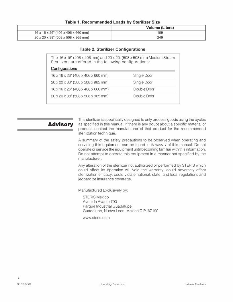
Table 1. Recommended Loads by Sterilizer SizeVolume (Liters)
16 x 16 x 26" (406 x 406 x 660 mm) 10920 x 20 x 38" (508 x 508 x 965 mm) 249
This sterilizer is specifically designed to only process goods using the cyclesas specified in this manual. If there is any doubt about a specific material orproduct, contact the manufacturer of that product for the recommendedsterilization technique.
A summary of the safety precautions to be observed when operating andservicing this equipment can be found in SECTION 1 of this manual. Do notoperate or service the equipment until becoming familiar with this information.Do not attempt to operate this equipment in a manner not specified by themanufacturer.
Any alteration of the sterilizer not authorized or performed by STERIS whichcould affect its operation will void the warranty, could adversely affectsterilization efficacy, could violate national, state, and local regulations andjeopardize insurance coverage.
Manufactured Exclusively by:
STERIS MexicoAvenida Avante 790Parque Industrial GuadalupeGuadalupe, Nuevo Leon, Mexico C.P. 67190
www.steris.com
Advisory
Table 2. Sterilizer Configurations
The 16 x 16" (406 x 406 mm) and 20 x 20: (508 x 508 mm) Medium SteamSterilizers are offered in the following configurations:
ConfigurationsConfigurationsConfigurationsConfigurationsConfigurations
16 x 16 x 26" (406 x 406 x 660 mm) Single Door
20 x 20 x 38" (508 x 508 x 965 mm) Single Door
16 x 16 x 26" (406 x 406 x 660 mm) Double Door
20 x 20 x 38" (508 x 508 x 965 mm) Double Door

iii
Table of Contents Operating Procedure 387352-364
1 LISTING OF WARNINGS AND CAUTIONS ....................................... 1-1Definition of Symbols ......................................................................................................... 1-4
2 INSTALLATION VERIFICATION ....................................................... 2-12.1 Installation Checklist ................................................................................................... 2-1
2.1.1 Service Clearance ............................................................................................... 2-12.1.2 Plumbing Services ............................................................................................... 2-1
2.2 Technical Specifications ............................................................................................. 2-22.2.1 Electrical Service ................................................................................................. 2-22.2.2 Sterilizer Final Check ........................................................................................... 2-22.2.3 Cycle Operation .................................................................................................. 2-22.2.4 Overall Size and Weight ...................................................................................... 2-22.2.5 Electrical Service ................................................................................................. 2-32.2.6 Environmental Conditions .................................................................................... 2-32.2.8 Environmental Conditions .................................................................................... 2-32.2.7 Utility Requirements For Units Equipped
With Optional Electric Steam Sterilizers .............................................................. 2-3
3 TECHNIQUES OF STERILIZATION .................................................. 3-13.1 Recommended Sterilization Variables ........................................................................ 3-1
3.1.1 Prevacuum Cycle ................................................................................................ 3-13.1.2 Gravity Cycle ....................................................................................................... 3-13.1.3 Liquid Cycle ........................................................................................................ 3-2
3.2 Control Measures for Verifying Sterilization Process .................................................. 3-33.2.1 Biological Monitors .............................................................................................. 3-33.2.2 Testing for Prevacuum Efficiency ....................................................................... 3-3
3.3 Bowie-Dick Test .......................................................................................................... 3-43.4 Vacuum Leak Test ....................................................................................................... 3-43.5 Recommendations for the Sterilization Process ......................................................... 3-53.6 Techniques of Sterilization for Liquid Cycle ................................................................ 3-63.7 Recommendations for Sterilizing Liquids ................................................................... 3-6
4 OPERATOR INSTRUCTIONS ............................................................ 4-1 4.1 Component Identification ........................................................................................... 4-1
4.1.1 Main Power Disconnect Switch ........................................................................... 4-24.1.2 Supply Valves ...................................................................................................... 4-2
4.2 Control Panel .............................................................................................................. 4-34.2.1 Touch Screen ....................................................................................................... 4-34.2.2 Printer (Optional) ................................................................................................. 4-34.2.3 Operating Mode .................................................................................................. 4-54.2.4 Cycle Start ........................................................................................................... 4-54.2.5 End-of-Cycle Performance Summary .................................................................. 4-54.2.6 Alarm Condition ................................................................................................... 4-5
4.3 Manual Operation of Manual Door .............................................................................. 4-64.4 Emergency Door Operation ........................................................................................ 4-74.5 Optional Electric Steam Generator ............................................................................. 4-9
TABLE OF CONTENTS
Section Paragraph Page

iv
387352-364 Operating Procedure Table of Contents
Section Paragraph Page
5 CONTROL INTERFACE .................................................................... 5-15.1 General Description .................................................................................................... 5-1
5.1.1 Information and Help ........................................................................................... 5-15.1.2 Password Entry ................................................................................................... 5-2
5.2 Operating Modes ........................................................................................................ 5-45.2.1 Gravity Sterilizer Only .......................................................................................... 5-45.2.2 Prevac Sterilizer Only (Optional) ......................................................................... 5-75.2.3 Isothermal Sterilizer Only (Optional) .................................................................. 5-10
5.3 Status Buttons ........................................................................................................... 5-135.4 Printer Operation (Optional) ...................................................................................... 5-17
5.4.1 Printer Operation (Optiona Cybertech Printer) ................................................. 5-175.4.2 Printer Operation (Optiona Mylox Printer) ........................................................ 5-18
5.5 Compact Flash Card ................................................................................................. 5-185.6 RS232 Download To PC ............................................................................................ 5-20
6 STERILIZER OPERATION ................................................................ 6-16.1 Before Operating Sterilizer ......................................................................................... 6-1
6.1.1 Load Sterilizer ...................................................................................................... 6-36.1.2 Sterilizer Equipped with Loading Car .................................................................. 6-3
6.2 Gravity Cycle .............................................................................................................. 6-56.3 Prevac Cycle (Optional) ............................................................................................ 6-116.4 Liquid Cycle .............................................................................................................. 6-186.5 Isothermal Cycle (Optional) ...................................................................................... 6-246.6 Bowie-Dick Warmup Cycle (Only On Prevacuum Sterilizers) ................................... 6-296.7 Bowie-Dick Cycle (Only On Prevacuum Sterilizers) ................................................. 6-346.8 Leak Test Cycle (Only On Prevacuum Sterilizers) .................................................... 6-406.9 Cycle Abort ............................................................................................................... 6-466.10 Double Doors .......................................................................................................... 6-476.11 Load Probe and Fo Sterilization (Sterilizers With Load Probe Only) ....................... 6-47
6.11.1 Fo Sterilization .................................................................................................. 6-476.12 Separate Steam Feed Option ................................................................................. 6-486.13 Supervisor Mode .................................................................................................... 6-48
6.13.1 Cycle Parameters ............................................................................................ 6-486.13.2 Too Long In Step ............................................................................................. 6-596.13.3 Cycle Count ..................................................................................................... 6-626.13.4 Units ................................................................................................................ 6-626.13.5 Set Time and Date ........................................................................................... 6-636.13.6 Set Passwords ................................................................................................. 6-636.13.7 Machine Number ............................................................................................. 6-656.13.8 Default Values .................................................................................................. 6-65

v
Table of Contents Operating Procedure 387352-364
7 ALARMS ........................................................................................... 7-1
8 ROUTINE MAINTENANCE ............................................................... 8-18.1 Service Mode .............................................................................................................. 8-1
8.1.1 Calibration ........................................................................................................... 8-18.1.2 I/O Test ................................................................................................................ 8-78.1.3 Serial Number ...................................................................................................... 8-88.1.4 Configure Machine .............................................................................................. 8-8
8.2 Change Printer Paper Roll (Cybertech Printer) ......................................................... 8-118.3 Change Printer Paper Roll (Mylox Printer) ................................................................ 8-138.4 Change Printer Ribbon (Mylox Printer) ..................................................................... 8-148.5 Clean Chamber Drain Strainer .................................................................................. 8-158.6 Flush Chamber Drain ................................................................................................ 8-15
9 PREVENTIVE MAINTENANCE ......................................................... 9-19.1 Maintenance Schedule ............................................................................................... 9-19.2 Spare Parts ................................................................................................................. 9-3
10 APPENDIX A ................................................................................. 10-110.1 PLC Specifications.................................................................................................. 10-1
Section Paragraph Page

1-1
Summary of Warnings and Cautions Operating Procedure 387352-364
The following is a list of the safety precautions which must be observed when operating this equipment. WARNINGSindicate the potential for danger to personnel, and CAUTIONS indicate the potential for damage to equipment.These precautions are repeated (in whole or in part), where applicable, throughout the manual. This is a listing ofall safety precautions appearing in the manual. Carefully read them before proceeding to use or service the unit.
WARNING–ELECTRIC SHOCK AND BURN HAZARD:
Disconnect all utilities to sterilizer before servicing. Do not service the sterilizer unless all utilities have beenproperly locked out. Always follow appropriate Lockout-Tagout and electrical safety-related work practicestandards.
WARNING–PERSONAL INJURY HAZARD:
When closing the chamber door, keep hands and arms out of the door opening and make sure opening isclear of obstructions.
WARNING–BURN HAZARD:
Sterilizer, rack/shelves, and loading car will be hot after cycle is run. Always wear protective gloves and apronwhen removing a processed load. Protective gloves and apron must be worn when reloading sterilizerfollowing the previous cycle.
Steam may be released from the chamber when door is opened. Step back from the sterilizer each time thedoor is opened to minimize contact with steam vapor.
Do not attempt to open the sterilizer door if a WATER IN CHAMBER ALARM condition exists. Call a qualifiedservice technician before attempting to use sterilizer further.
After manual exhaust, steam may remain inside the chamber. Always wear protective gloves, apron, and aface shield when following emergency procedure to unload sterilizer. Stay as far back from the chamberopening as possible when opening the door.
Allow sterilizer to cool to room temperature before performing any cleaning or maintenance procedures.
Failure to shut off the steam supply when cleaning or replacing strainers can result in serious injury.
Jacket pressure must be 0 psig (0 bar) before beginning work on the steam trap.
Proper testing of the safety valve requires the valve to be operated under pressure. Exhaust from the safetyvalve is hot and can cause burns. Proper safety attire (gloves, eye protection, insulated overall) is required.Testing is to be performed by qualified service personnel only.
When sterilizing liquids, to prevent personal injury or property damage resulting from bursting bottles and hotfluid, you must observe the following procedures:
• Use LIQUID cycle only; no other cycle is safe for processing liquids.
• Use only vented closures; do not use screw caps or rubber stoppers with crimped seal.
• Use only Type 1 borosilicate glass bottles; do not use ordinary glass bottles or any container not designedfor sterilization.
• Do not allow hot bottles to be jolted; this can cause hot-bottle explosions. Do not move bottles if any boilingor bubbling is present.
LISTING OF WARNINGS AND CAUTIONS 1

1-2
387352-364 Operating Procedure Summary of Warnings and Cautions
WARNING–BURN HAZARD:
Sterilizer operator may be severely burned by scalding water if the water level control malfunctions. The steamgenerator level control may malfunction if the supply water exceeds 26,000 ohms/cm (38.5 microohms)conductivity minimum. Do not connect treated water (e.g., distilled, reverse osmosis, deionized) unless waterresistivity is determined to be acceptable. If water exceeds 26,00 ohms/cm, contact STERIS for informationconcerning modifications required to the generator control system.
WARNING – EXPLOSION HAZARD:
This sterilizer is not designed to process flammable compounds.
WARNING – SLIPPING HAZARD:
To prevent falls, keep floors dry by immediately wiping up any spilled liquids or condensation in sterilizerloading or unloading area.
WARNING–PERSONAL INJURY AND/OR EQUIPMENT DAMAGE HAZARD:
Regularly scheduled preventive maintenance is required for safe and reliable operation of this equipment.Contact STERIS to schedule preventive maintenance.
Repairs and adjustments to this equipment must be made only by fully qualified service personnel.Maintenance performed by inexperienced, unqualified persons or installation of unauthorized parts couldcause personal injury or result in costly equipment damage.
The configure machine section should only be done in the factory or by a qualified service technician.
WARNING – STERILITY ASSURANCE HAZARD:
Load sterility may be compromised if the biological indicator or air leak test indicates a potential problem. Ifthese indicators show a potential problem, refer the situation to a qualified service technician before usingthe sterilizer further.

1-3
Summary of Warnings and Cautions Operating Procedure 387352-364
CAUTION – POSSIBLE EQUIPMENT DAMAGE:
Gasket must be fully retracted prior to operating sterilizer door.
Do not try to raise or lower door rapidly as fast operation may damage the manual door mechanism.
If 0 dry time is selected, sterilizer automatically initiates a vapor removal phase in place of drying. This phasecan still draw a vacuum to 5 inHg. Consult device manufacturer’s recommendations to verify devices beingprocessed can withstand this depth of vacuum.
Lifting the chamber float switch when cleaning the chamber may cause the sterilizer control to initiate aChamber Flooded alarm. If this alarm condition occurs, the operator must turn the control power OFF thenON to clear the alarm. The control power switch is located in the mechanical area at the side of the sterilizer.Placing the sterilizer in standby does not clear this alarm.
Allow thermostatic traps to cool down to room temperature before removing cover. Since there is nothing tolimit expansion, the bellows may rupture or fatigue if trap is opened while hot.
Actuation at less than 75% of rated pressure can allow debris to contaminate the seat and cause the safetyvalve to leak. A leaking safety valve must be replaced.
Insufficient service clearance will make repairs more difficult and time-consuming.
Piping sized too small may cause water hammer, resulting in damage to the sterilizer.
After installation, it is mandatory to brace piping at the drain funnel so that it will not move vertically.
Make sure door opening is clear of any obstruction before closing the door(s).
Do not attempt to open sterilizer door during manual operation unless chamber is at 0 psig (0 bar).
Never use a wire brush, abrasives, or steel wool on door and chamber assembly. Do not use cleanerscontaining chloride on stainless-steel surfaces. Chloride-based cleaners will deteriorate stainless steel,eventually leading to failure of the vessel.
Immediately wipe up saline solution spills on loading car, to prevent damage to stainless steel.
Do not use cleaners containing chlorides on loading cars. Chloride-based cleaners will deteriorate the loadingcar metal.
Sterilization of chloride-containing solutions (e.g., saline) can cause chamber corrosion and is not recom-mended by the manufacturer. If, however, chloride-containing solutions must be processed, clean thechamber after each use.
Avoid damage to the integral steam generator daily. Flush the generator daily. Failure to flush generator dailywill void the manufaturer’s warranty.

1-4
387352-364 Operating Procedure Summary of Warnings and Cautions
Symbol Definition
Transfer of Heat, Hot Surface
Protective Earth (Ground)
Electrostatic Sensitive Device
Attention, Consult Manual forFurther Instructions
A Amperage Rating of the unit
V Voltage Rating of the unit
~ Alternating Current
Hz Frequency of the unit
φφφφφ Phase of the unit
SN Serial Number of Unit
Definition ofSymbols

2-1
Installation Verification Operating Procedure 387352-364
An equipment drawing showing all utility and space requirements wassupplied with the sterilizer. Clearance space shown on the drawing isnecessary for ease of installation and to help ensure proper operation andmaintenance of equipment. Uncrating and Installation Instructions were alsofurnished with the sterilizer. If any of these documents are missing ormisplaced, contact STERIS giving the serial and model numbers of theequipment. Replacement copies will be sent out promptly.
After installing this unit according to the instructions provided, complete thefollowing checklist to help ensure installation is complete and correct. Or, ifdesired, call STERIS to schedule a technician to test the installation anddemonstrate proper equipment operation.
• Clearance as specified on the equipment drawing must be available.
• Feed Water:• All supply line shutoffs must be provided with lockout capability.
• Backflow prevention is not provided by STERIS.
• Water Pressure–measured (specification is 1.4 to 3.5 bar [20 to 50 psig],dynamic). Water pressure supplied must be within specifications asshown on the equipment drawing. If pressure is too high, a regulator mustbe installed. If water pressure is too low, equipment performance isaffected.
• Water Quality–supplied must be within specifications. Improper waterquality adversely affects equipment operation. Damage to the equipmentdue to improper water quality is not covered under warranty.
• Steam Supply:• Shutoffs (with provisions for lockout and tagout) located nearby.
• Supply piping adequately sized.
• Supply pressure measured (specification is 3.5 to 5.2 bar [50 to 80 psig],dynamic).
• Drain piping must be sloped properly, and sized to handle the maximumwaste flow from the sterilizer.
2.1 InstallationChecklist
CAUTION - POSSIBLEEQUIPMENT DAMAGE HAZ-ARD: Insufficient serviceclearance will make repairsmore difficult and time-con-suming.
INSTALLATION VERIFICATION 2
2.1.1 Service Clearance
2.1.2 Plumbing Services

2-2
387352-364 Operating Procedure Installation Verification
• Electric single-phase service to the unit must be as specified on theEquipment Drawing and on the Machine Data Plate.
• Electric single-phase service requires a clearly marked disconnect withlockout/tagout capability located near the sterilizer.
• Electric single-phase service should be on a separate circuit, and not tiedinto circuits containing large reactive loads (e.g., motors).
• The sterilizer's protective ground must be connected to terminal block TB-1 in the sterilizer power box. Use green/yellow wire for European installa-tions.
• 3-phase service requires a clearly marked disconnect with lockout/tagoutcapability located near the sterilizer.
• Chamber must be leveled properly.
• Door must open and close smoothly.
• Door locked switches must be adjusted correctly.
• Chamber strainer must be in place.
• Rack and shelves and/or loading car operates correctly.
• Warranty labels properly applied.
• Unit powers up correctly.
• Run Leak Test cycle–leak rate is to be less than 1.0 mm Hg/minute(1.3 mbar/minute). Only on prevac sterilizers.
• Verify operation of a typical cycle (121° C [250°F] gravity).
• 16 x 16 x 26" 660 mm wide x 1892 mm high x 902 mm deepSterilizer: (26" wide x 74.5" high x 35.5" deep)
• 20 x 20 x 38" 762 mm wide x 1892 mm high x 1152 mm deepSterilizer: (30" wide x 74.5" high x 45.375" deep)
2.2 TechnicalSpecifications
2.2.1 Electrical Service
2.2.2 Sterilizer Final Check
2.2.3 Cycle Operation
2.2.4 Overall Size andWeight

2-3
Installation Verification Operating Procedure 387352-364
• Electric:Controls: 120 VAC, 2.5A, 1-phase, 50/60 hz
Generator Heaters: 208 VAC, 83.2A, 3-phase, 50/60 hz
440/480 VAC, 31/37A, 3-phase, 50/60 hz
240 VAC, 72.2A, 3-phase, 50/60 hz
• Hot Water:Pressure: 137.9 to 344.7 Kpa (20 to 50 psig)Temperature: 140°F, maximumConsumption: Peak 1gpm, per cycle 4 gal, Idle 1 gph
• Stainless-Steel Option Only:Distilled, Reverse-Osmosis (RO), or Deionized Water with a minimumspecific resistivity of 1 mΩ/cm.
• Cold Water:
2.2.7 Utility RequirementsFor Units Equipped WithOptional Electric Steam
Sterilizers
2.2.8 EnvironmentalConditions
Pressure: 206.8 to 344.7 Kpa (30 to 50 psig)Temperature: 70°F (21oC, maximumConsumption: Peak 6gpm, per cycle 140 gal, Idle 10 gph
Temperature: 10° to 32°C (50° to 90°F)Humidity: 10 to 90% noncondensingPollution Degree: 2Installation Category (Overvoltage Category): IIA-Weighted Sound Power Level: 85 dBA (maximum)
• Electric:Controls: 230 VAC, 1.5A, 1-phase, 50/60 hz
Vacuum Pump: 120 VAC, 9.5A, 1-phase, 50/60 hz
440/480 VAC, 31/37A, 3-phase, 50/60 hz
240 VAC, 72.2A, 3-phase, 50/60 hz
• Steam:Pressure: 50 to 80 psig (344.7 to 551.6 Kpa)Consumption:• 16 x 16 x 26" (406 x 406 x 660 mm) 83 lb/hr (38 kg/hr ) peak• 20 x 20 x 38" (508 x 508 x 965 mm) 116 lb/hr (53 kg/hr ) peak
• Cold Water:Pressure: 206.8 to 344.7 Kpa (30 to 50 psig)Temperature: 70°F (21oC, maximumConsumption: Peak 6gpm, per cycle 140 gal, Idle 10 gph
2.2.5 Electrical Service
2.2.6 EnvironmentalConditions
Temperature: 10° to 32°C (50° to 90°F)Humidity: 10 to 90% noncondensingPollution Degree: 2Installation Category (Overvoltage Category): IIA-Weighted Sound Power Level: 85 dBA (maximum)

3-1Techniques of Sterilization Operator Manual 387352-364
TECHNIQUES OF STERILIZATION
3.1 RecommendedSterilization
Variables
3
Table 3-1. Prevacuum Cycle Parameters
Minimum RecommendedPressure Point Sterilize Time*
Temperature Psig (psia) Minutes at Temperature
121°C (250°F) 12-14 (27-29) 15
132°C (270°F) 26-28 (40-42) 4
* Minimum sterilize times are based on obtaining a 106 Sterility Assurance Level (SAL)with standard test loads. Your specific lads may require different sterilize times toachieve this level of sterility, or you may require a different SAL.
3.1.1 Prevacuum Cycle The Prevacuum cycle is recommended to process heat- and moisture-stablegoods, except liquids, which are capable of being sterilized with steam. Thiscycle can also be used to decontaminate wastes, including wastes containingliquids, provided the materials are properly contained.
Refer to Table 3-1 for recommended Prevacuum cycle parameters.
Table 3-2. Gravity Cycle Parameters
Minimum MinimumRecommended RecommendedSterilize Time at Sterilize Time at
Items 121°C (250°F) 132°C (270°F) Dry Time(minutes) (minutes) (minutes)
Glassware 15 Min. 3 Min. 0 Min.**Empty,
inverted,vented*
Instruments 20 Min. 10 Min. 0 Min.**metal combined
with suture,tubing or
other porousmaterials
(unwrapped)
Hard Goods 15 Min. 3 Min. 0 Min.**Unwrapped
3.1.2 Gravity Cycle Refer to Table 3-2 for the type of items which can be processed in a Gravitycycle and the recommended parameters.

3-2387352-364 Operator Manual Techniques of Sterilization
Table 3-2. Gravity Cycle Parameters (cont.)
Minimum MinimumRecommended RecommendedSterilize Time at Sterilize Time at
Items 121°C (250°F) 132°C (270°F) Dry Time(minutes) (minutes) (minutes)
Hard Goods 30 Min. 15 Min. 30 Min.Wrapped in
muslin orequivalent
* If items which can trap air must be sterilized upright, they should be sterilized ina prevacuum cycle.** Goods will be wet when removed from sterilizer.*** Dry time can vary for wrapped goods depending on pack density, weight ofgoods, pack preparation techniques including type of wrapping material used,and sterilizer loading procedures.
Table 3-3. Liquid Cycle Parameters - No Load Probes
Volume of Liquid Minimum Recommendedin One Container Sterilize Time* at 121°C (250°F)
(mL) (minutes)
75 25
250 30
500 40
1000 45
1500 50
2000 55
>2000 55+10 min/L
* Minimum sterilize times are based on obtaining a 106 Sterility Assurance Level (SAL)with standard test loads. Specific labs may require different sterilize times to achievethis level of sterility, or may require a different SAL.
3.1.3 Liquid Cycle Refer to Table 3-3 for recommended Liquid cycle parameters. The recom-mended times indicated in Table 3-3 assume the use of vented bottles orErlenmeyer flasks. The minimum sterilization time includes the time requiredto bring the solution up to the sterilization temperature plus the time requiredto achieve sterilization.
NOTE: Use load probes and Fo option to optimize cycle times.

3-3Techniques of Sterilization Operator Manual 387352-364
3.2.2 Testing forPrevacuum Efficiency
3.2 ControlMeasures
for VerifyingSterilization Process
3.2.1 Biological Monitors
WARNING – STERILITY AS-SURANCE HAZARD: Loadsterility may be compro-mised if the biological indi-cator or vacuum leak testindicates a potential prob-lem. If these indicators showa potential problem, referthe situation to a qualifiedservice technician beforeusing the sterilizer further.
A live spore test utilizing B. stearothermophilus is the most reliable form ofbiological monitoring. This type of product utilizes controlled populations of acontrolled resistance, so that survival time and kill time can be demonstrated.
To verify the process, insert the biological indicator in a test pack and placepack on the bottom shelf. Run test pack through a typical cycle. On comple-tion, forward test pack and monitor to appropriate personnel for evaluation.
Tests such as the Bowie-Dick (using a STERIS Dart® test pack*) aredesigned to document the removal of residual air from a sample challengeload.
Run a Bowie-Dick test cycle daily before processing any loads in asterilizer equipped with prevacuum cycles. The first prevacuum cycle ofeach day should be used to test the adequacy of air removal from thechamber and load, so that steam can penetrate the load. It is not a test foradequate exposure to heat in terms of time-at-temperature.
In the case of these tests, following exposure in a prevacuum sterilizingcycle, the pack is opened, the indicator examined, and conclusions aredrawn as to the pattern of residual air, if any, that remained in the packduring the sterilizing cycle. Any indication of a malfunction must bereported to the supervisor. Sterilizer must not be used again until ap-proved by supervisor.
* Call STERIS for pricing and availability.

3-4387352-364 Operator Manual Techniques of Sterilization
3.3 Bowie-DickTest
3.4 VacuumLeak Test
The Bowie-Dick Test is designed to document the removal of residual air froma sample challenge load in a prevacuum sterilizer. This test does not applyto gravity, liquids, or Isothermal cycles.
In the case of this test, following exposure in a prevacuum test cycle, thepack is opened, the indicator examined and conclusions are drawn as tothe pattern of residual air, if any, that remained in the pack during thesterilizing cycle. Any indication of a malfunction must be reported to thesupervisor. Sterilizer must not be used to run prevacuum cycles untilapproved by supervisor.
Refer to instructions for running the Bowie-Dick test cycle in SECTION 6,STERILIZER OPERATION. Dart (Bowie-Dick) test packs* are designed to exposethe pattern and document the removal of residual air from the sample load.
NOTE: The Bowie-Dick test cycle is not a test for adequate exposure toheat in terms of time-at-temperature.
* Call STERIS for pricing and availability.
The Vacuum Leak Test (see appropriate cycle description in SECTION 5,CONTROL INTERFACE) measures the integrity of the sealed pressure vessel andassociated piping to verify air is not being admitted to the sterilizer during thevacuum drawdowns.
After running a Leak Test cycle, a value or leak rate prints on the printer tape.This value helps define a trend over a period of time if the integrity of the systembegins to deteriorate (i.e., allowing air to enter the system). By running a LeakTest cycle daily or weekly, the operator or maintenance personnel can alwaysmonitor the air tightness of the system and make repairs or adjustments whennecessary.
NOTE: A leak rate of greater than 1 mmHg per minute indicates a problem withthe sterilizer that must be addressed.
WARNING – STERILITY AS-SURANCE HAZARD: Loadsterility may be compro-mised if the biological indi-cator or vacuum leak testindicates a potential prob-lem. If these indicators showa potential problem, referthe situation to a qualifiedservice technician beforeusing the sterilizer further.
WARNING – STERILITY AS-SURANCE HAZARD: Loadsterility may be compro-mised if the biological indi-cator or vacuum leak testindicates a potential prob-lem. If these indicators showa potential problem, referthe situation to a qualifiedservice technician beforeusing the sterilizer further.

3-5Techniques of Sterilization Operator Manual 387352-364
3.5 Recommendationsfor the Sterilization
Process
Saturated steam is a well controlled, reliable method for processing itemswhich can withstand the temperatures and pressures associated with steamsterilization. The requirements for achieving reproducible results are wellknown by many users, but are not always understood by all users.
The condition most likely to result in sterilization problems is a failure to removeall of the air from the items being processed. For example, placing an emptybeaker or bowl in an upright position in a gravity displacement sterilizer mayresult in the object not being sterilized, or may require exceptionally longsterilization times. This problem is due to the fact air has almost twice thedensity as does saturated steam under the same conditions. Thus, the air sitsin the bottom of the container, and the steam forms a stable layer over the air.This effect is similar to oil forming a stable layer over water. As long as thereis no mechanism for actively mixing the two, the bottom of the container onlyis exposed to dry heat only, which is not an effective sterilization method at thetime and temperatures typically used in steam processes.
There are two traditional methods for enhancing the sterilization of solid bottomcontainers in gravity displacement cycles. These are:
• Place 1 mL of water for each liter of volume in the bottom of each container.The expansion of the water into steam, as the product is heated, forcesmost of the air out of the object, thus allowing steam to reach all surfacesand effect sterilization.
• The better, more reliable method is to orient all objects in a manner whichwould allow water to flow out. When the steam enters the chamber, it tendsto layer over the air. When inverted, however, the object is oriented so aircan flow out. As air flows out of the container, it is replaced by steam.Steam can now reach all surfaces, and effect sterilization.

3-6387352-364 Operator Manual Techniques of Sterilization
Refer to Table 3-4 for suggested Liquid cycle parameters. The suggestedtimes indicated in Table 3-4 assume the use of vented bottles. The minimumsterilization time includes the time required to bring the solution up to thesterilize temperature plus the time required to achieve sterilization. This timemay vary due to viscosity of liquid and other parameters.
3.6 Techniques ofSterilization for
Liquid Cycle
Table 3-4. Liquid Cycle Parameters
Minimum RecommendedNumber of Volume of Liquid Sterilize Time at 250°F (121°C)Containers in One Container in Minutes
3 1000 mL 45
WARNING–EXPLOSIONHAZARD: This sterilizer isnot designed to processflammable compounds.
WARNING–PERSONAL IN-JURY HAZARD: Avoid per-sonal injury from burstingbottles. Liquid sterilizationcycle must only be used forliquids in borosilicate (Pyrex)flasks with vented closures.
WARNING: When sterilizingliquids, you must observethe following procedures:
• Use Liquid cycle only.
• Use only vented closures.
• Use only Type I borosilicateglass bottles.
• Do not allow hot bottles tobe jolted.
WARNING–BURN HAZARD:Steam may be released fromthe chamber when door isopened. Step back from thesterilizer each time the dooris opened to minimize con-tact with steam vapor.
CAUTION: Sterilization ofchloride-containing solu-tions (e.g., saline) can causechamber corrosion and is notrecommended by the manu-facturer. If, however, chlo-ride-containing solutionsmust be processed, clean thechamber after each use.

3-7Techniques of Sterilization Operator Manual 387352-364
Figure 3-1. Vented Closures
Morton Closure
Tab
Tab
After Sterilization
Before Sterilization
Morton Closure
IMPORTANT: Please read the following paragraphs before sterilizing anyliquids in the sterilizer.
Borosilicate glass is required because it is a superior glass capable ofresisting thermal shock. If glass not as thermally resistant is used, a greaterpotential for bursting exists.
Vented closures are required because, by design, they release internalpressure build-up by automatically venting the containers, whereas pressurein unvented containers remains until the contents have cooled. Examples ofvented closures are shown in Figure 3-1.When loading, place small bottles in a separate basket to minimize sliding.Always use side rails on the loading car to prevent containers or baskets fromfalling off.
3.7 Recommendationsfor Sterilizing
Liquids
WARNING – EXPLOSIONHAZARD: This sterilizer isnot designed to processflammable compounds.
WARNING – PERSONAL IN-JURY HAZARD: Avoid per-sonal injury from burstingbottles. Liquid sterilizationcycle must only be used forliquids in borosilicate flaskswith vented closures.
WARNING – BURN HAZ-ARD: When sterilizing liq-uids, always observe the fol-lowing procedures:
• Use Liquid cycle only.
• Use only vented closures.
• Use only Type I borosilicateglass bottles.
• Do not allow hot bottles tobe jolted.
• WARNING–BURN HAZ-ARD: Steam may be releasedfrom the chamber when dooris opened. Step back fromthe sterilizer each time thedoor is opened to minimizecontact with steam vapor.
CAUTION: Sterilization ofchloride-containing solu-tions (e.g., saline) can causechamber corrosion and is notrecommended by the manu-facturer. If, however, chlo-ride-containing solutionsmust be processed, clean thechamber after each use.

4-1
Operator Instructions Operating Procedure 387352-364
4.1 ComponentIdentification
The Lab 250 and Lab 110 Life Sciences Small Steam Sterilizers are steam-jacketed sterilizers designed to process a variety of loads using saturatedsteam under pressure and gravity air removal principals.
The Sterilizer is equipped with a fully-programmable microcomputer controlsystem capable of storing process cycles for sterilizing hard goods, lightlywrapped porous loads and liquid loads in vented containers. The controlsystem monitors and automatically controls all cycle operations and functions.
Before operating the sterilizer, it is important to become familiar with thelocation and function of all major components and controls (see Figure 4-1).
Figure 4-1. Lab 250 Series Sterilizer
OPERATOR INSTRUCTIONS 4

4-2
387352-364 Operating Procedure Operator Instructions
The main power disconnect switch, located behind the front cabinet panel,controls power supply to the sterilizer and control system (see Figure 4-2).
Important: This switch should remain in the ON position at all times for normalunit operation.
Supply valves to the sterilizer are located behind the front cabinet panel.Steam supply valve is located above the chamber door (see Figure 4-3); watersupply valve is located below the chamber door (see Figure 4-3).
NOTE: If unit is equipped with electric steam generator, refer to SECTION 4.5-OPTIONAL ELECTRIC STEAM GENERATOR, included in this section, for location of thegenerator supply valve.
Important: Both supply valves to the sterilizer should remain in the ONposition at all times for normal unit operation.
Figure 4-2. Main Power Disconnect Switch
Figure 4-3. Steam and Water Supply Valves to theSterilizer
W A R N I N G - E L E C T R I CSHOCK AND BURN HAZ-ARD: Disconnect all utilitiesto sterilizer before servic-ing. Do not service the ster-ilizer unless all utilities havebeen properly locked out.Always follow appropriateLockout-Tagout and electri-cal safety-related work prac-tice standards.
4.1.1 Main PowerDisconnect Switch
4.1.2 Supply Valves
JACKET
CHAM BER
Steam SupplyValveON
OFF
Steam Valve Located AboveChamber Door
Water SupplyValve
ON
OFF
Water Valve Located Below Chamber Door

4-3
Operator Instructions Operating Procedure 387352-364
The control panel, located on load end of the sterilizer, is used to direct allsterilizer functions (see Figure 4-4). The operator may control cycle operation,program cycles and sterilizer operating parameters and monitor cycle perfor-mance from the control panel.
The touch screen allows the user to operate and program the sterilizer controlby touching (pressing) the appropriate touch-sensitive areas on the display.On each screen, all rectangular-outlined boxes are touch-sensitive areas,referred to as buttons (see Figure 4-4).
Refer to SECTION 5, CONTROL INTERFACE, for further details on interfacing with thecontrol system’s touch screen.
Figure 4-4. Example of In-cycle Touch Screen
Ink-on-paper printer records all cycle data on 2-1/4" wide paper.
The following is an example of a typical in-cycle printout in the condensed printformat (see Figure 4-5).
4.2 Control Panel
4.2.1 Touch Screen
4.2.2 Printer (Optional)
XX:XX:XX XM
XX/XX/XXXXScreen #4

4-4
387352-364 Operating Procedure Operator Instructions
Figure 4-5. Condensed Printout
All printer functions are controlled using the touch screen. For details on eachof the printer functions, refer to SECTION 5, CONTROL INTERFACE.
NOTE: Extended print format is available.

4-5
Operator Instructions Operating Procedure 387352-364
When sterilizer is placed in the Operating mode, the generated printout liststhe sterilizer type and manufacturer.
CONTROL ONDay, Month XX, XXXXXX:XX:XX AM******************************* STERIS SCIENTIFIC ** LAB 110 / 250 SERIES ** GRAVITY STERILIZER ** MADE IN U.S.A. *******************************
******************************
When a cycle is started, the generated printout lists name of cycle started, timeand date the cycle was started, the current cycle count (number of cycles runsince original start up of unit), the operator’s name, the sterilizer ID number, thedefault cycle number and type, and the programmed parameters for the cyclestarted.
NOTE: Cycle count value may be changed in the Supervisor Mode.
At the end of a cycle, the generated printout lists number of cycles run that day,the maximum and minimum chamber temperatures reached during thesterilize phase, processing times for key phases and the total cycle time.
When an alarm condition occurs, the generated printout (see Figure 4-6) liststhe type of alarm and time, chamber temperature and chamber pressure whenit occurred.
NOTE: Refer to SECTION 7, ALARMS, for listing of possible alarm conditions.
* ALARMPRESSURE IN CHAMBER
F 10:07:23A 61.7C 34.0P
Figure 4-7. Printout: Type of Alarm, Chamber Temperatureand Chamber Pressure, and Time of Occurrence
4.2.3 Operating Mode
4.2.4 Cycle Start
4.2.5 End-of-CyclePerformance Summary
4.2.6 Alarm Condition
Figure 4-6. Printout: Sterilizer Type and Manufacturer

4-6
387352-364 Operating Procedure Operator Instructions
4.3 Manual Operationof Manual Door
Carefully review SECTION 1, SAFETY PRECAUTIONS, and below before operatingdoor manually.
Using hand pressure, pull up or push down on the door handle to operate thedoor.
NOTE: Do not try to raise or lower door rapidly as fast operation may damagethe door drive mechanism.
WARNING - PERSONAL INJURY HAZARD: When closing the chamber door, keep hands and arms outof the door opening and make sure opening is clear of obstructions.
WARNING - BURN HAZARD:
• Steam may be released from the chamber when door is opened. Step back from the sterilizer each timethe door is opened to minimize contact with steam vapor.
• Do not attempt to open the sterilizer door if a WATER IN CHAMBER ALARM condition exists. Call aqualified service technician before attempting to use sterilizer further.
• After manual exhaust, steam may remain inside the chamber. Always wear protective gloves, apron,and a face shield when following emergency procedure to unload sterilizer. Stay as far back from thechamber opening as possible when opening the door.
CAUTION - POSSIBLE EQUIPMENT DAMAGE HAZARD:
• Gasket must be fully retracted prior to operating sterilizer door.
• Make sure door opening is clear of any obstruction before closing the door(s).
• Do not attempt to open sterilizer door during manual operation unless chamber is at 0 psig (0 bar).
• Do not try to raise or lower door rapidly as fast operation may damage the manual door mechanism.

4-7
Operator Instructions Operating Procedure 387352-364
4.4 Emergency DoorOperation
Carefully review SECTION 1, SAFETY PRECAUTIONS, and below before operatingemergency door. (Refer to page 4-8 for procedure.)
WARNING - BURN HAZARD:
• Do not attempt to open the sterilizer door if a WATER IN CHAMBER ALARM condition exists. Call aqualified service technician before attempting to use sterilizer further.
• After manual exhaust, steam may remain inside the chamber. Always wear protective gloves, apron,and a face shield when following emergency procedure to unload sterilizer. Stay as far back from thechamber opening as possible when opening the door.
• Allow sterilizer to cool to room temperature before performing any cleaning or maintenance proce-dures.
• Do not attempt to open the sterilizer door if a WATER IN CHAMBER ALARM condition exists. Call aqualified service technician before attempting to use sterilizer further.
• Failure to shut off the steam supply when cleaning or replacing strainers can result in serious injury.
• Jacket pressure must be 0 psig (0 bar) before beginning work on the steam trap.
• Proper testing of the safety valve requires the valve to be operated under pressure. Exhaust from thesafety valve is hot and can cause burns. Proper safety attire (gloves, eye protection, insulated overall)is required. Testing is to be performed by qualified service personnel only.
• When sterilizing liquids, to prevent personal injury or property damage resulting from bursting bottlesand hot fluid, you must observe the following procedures:
- Use LIQUID cycle only; no other cycle is safe for processing liquids.
- Use only vented closures; do not use screw caps or rubber stoppers with crimped seal.
- Use only Type 1 borosilicate glass bottles; do not use ordinary glass bottles or any container notdesigned for sterilization.
- Do not allow hot bottles to be jolted; this can cause hot-bottle explosions. Do not move bottles if anyboiling or bubbling is present.
WARNING - EXPLOSION HAZARD: This sterilizer is not designed to process flammable compounds.
WARNING - PERSONAL INJURY AND/OR EQUIPMENT DAMAGE HAZARD: Repairs and adjustments tothis equipment must be made only by fully qualified service personnel. Maintenance performed byinexperienced, unqualified persons or installation of unauthorized parts could cause personal injury orresult in costly equipment damage.
CAUTION - POSSIBLE EQUIPMENT DAMAGE HAZARD:
• Gasket must be fully retracted prior to operating sterilizer door.
• Do not attempt to open sterilizer door during manual operation unless chamber is at 0 psig (0 bar).

4-8
387352-364 Operating Procedure Operator Instructions
The following emergency procedure should only be used in instances wherethe sterilizer has lost either electrical or water utilities, and a load is sealed inthe chamber. This procedure requires manually releasing the door seal bypressing on the door and pushing the seal back into the groove.
1. Open front cabinet panel. Open manual exhaust valve to exhaust remain-ing steam from the chamber (see Figure 4-8). Leave valve open duringemergency procedure.
2. Using pressure tool provided, press on upper left hand and right handcorners of chamber door as shown in figure 4-8. Door should give inwardslightly, indicating seal has been compressed into groove.
3. Close front cabinet panel and pull down on door handle.
4. Once door is open, do not use sterilizer until unit has been examined by aqualified service technician. Further use without proper attention maydamage sterilizer.
5. Close manual exhaust valve.
Figure 4-8. Emergency Door Operation
3. Insert PressureTool
2. OpenManualExhaust
Valve
1. CheckChamberPressureGauge
4. Press on Upper Left-hand and Right-hand
Corners by PullingPressure Tool Away
from Unit

4-9
Operator Instructions Operating Procedure 387352-364
4.5 Optional ElectricSteam Generator
Carefully review SECTION 1, SAFETY PRECAUTIONS and below before operatingsteam generator. If a building steam source is not available, the sterilizer maybe equipped with an electric steam generator. The generator automaticallyconverts water to steam using electric heat. The steam created is then usedto power the sterilizer.
Steam generators are highly susceptible to mineral scaling if the suppliedwater has any level of hardness. Refer to Table 4-1 for water quality require-ments.
IMPORTANT: Regardless of the hardness level of supplied water, the genera-tor must be flushed every day before use to prevent mineral scaling or carryoverof debris into the chamber.
WARNING - BURN HAZARD:
• Do not attempt to open the sterilizer door if a WATER IN CHAMBER ALARM condition exists. Call aqualified service technician before attempting to use sterilizer further.
• After manual exhaust, steam may remain inside the chamber. Always wear protective gloves, apron,and a face shield when following emergency procedure to unload sterilizer. Stay as far back from thechamber opening as possible when opening the door.
• Allow sterilizer to cool to room temperature before performing any cleaning or maintenance proce-dures.
• Do not attempt to open the sterilizer door if a WATER IN CHAMBER ALARM condition exists. Call aqualified service technician before attempting to use sterilizer further.
• Failure to shut off the steam supply when cleaning or replacing strainers can result in serious injury.
• Jacket pressure must be 0 psig (0 bar) before beginning work on the steam trap.
• Proper testing of the safety valve requires the valve to be operated under pressure. Exhaust from thesafety valve is hot and can cause burns. Proper safety attire (gloves, eye protection, insulated overall)is required. Testing is to be performed by qualified service personnel only.
• When sterilizing liquids, to prevent personal injury or property damage resulting from bursting bottlesand hot fluid, you must observe the following procedures:
- Use LIQUID cycle only; no other cycle is safe for processing liquids.
- Use only vented closures; do not use screw caps or rubber stoppers with crimped seal.
- Use only Type 1 borosilicate glass bottles; do not use ordinary glass bottles or any container notdesigned for sterilization.
- Do not allow hot bottles to be jolted; this can cause hot-bottle explosions. Do not move bottles if anyboiling or bubbling is present.
WARNING - EXPLOSION HAZARD: This sterilizer is not designed to process flammable compounds.
WARNING - PERSONAL INJURY AND/OR EQUIPMENT DAMAGE HAZARD: Repairs and adjustments tothis equipment must be made only by fully qualified service personnel. Maintenance performed byinexperienced, unqualified persons or installation of unauthorized parts could cause personal injury orresult in costly equipment damage.
CAUTION - POSSIBLE EQUIPMENT DAMAGE HAZARD:
• Gasket must be fully retracted prior to operating sterilizer door.
• Do not attempt to open sterilizer door during manual operation unless chamber is at 0 psig (0 bar).

4-10
387352-364 Operating Procedure Operator Instructions
1. After the operating mode is entered, see CONTROL INTERFACE sectionfor instructions on entering the operating mode, the display shows thefollowing screen (the screen is shown only one time per day):
Condition Nominal MaximumRecommended Recommended
Temperature As Supplied 140° F (60° C)
Total Hardness as CaCO3* 0-17 mg/L 130 mg/L
Total Dissolved Solids 50-150 mg/L 250 mg/L
Total Alkalinity as CaCO3 50-100 mg/L 180 mg/L
pH 6.8 - 7.5 6.5 - 8.5
Total Silica 0.1 - 1.0 mg/L 2.5 mg/L
Resistivity - ohms/cm 2000-6000 26,000
*17.1 mg/L = 1 grain hardness
Table 4-1. Required Feed Water Quality for Carbon SteelSteam Generators
XX:XX:XX XM
XX/XX/XXXXScreen #84

4-11
Operator Instructions Operating Procedure 387352-364
2. Check generator pressure gauge (see Figure 4-9). Generator must be at 0psig and room temperature before flushing.
NOTE: If generator is not at 0 psig, the flush phase can be bypassed by pressingCANCEL; however , the flush should not be bypassed on a continuous basisor damage to the generator occurs.
To verify generator is at 0 psig, the sterilizer can be shut off at end of the dayand by next morning the unit is able to be flushed. Approximately seven hoursis required for generator to cool down to less than 140ºF (60ºC).
3. Open drain valve on side of generator electric box (see Figure 4-9).
4. Verify water supply valve to sterilizer is open.
5. Verify water supply to generator is open (see Figure 4-9).
6. Press START TIMER button on screen. Water automatically flushes throughgenerator and out the drain for five minutes. Flush timer on screen countsdown time remaining in flush phase.
7. After five minutes, display advances to the following screen. Instructions onhow to start generator are also listed on the screen.
XX:XX:XX XM
XX/XX/XXXX
GeneratorPressure Gauge
Water-levelSight Glass
Water Supply Valve tothe Generator
Figure 4-9. Optional Electric Steam Generator
Generator Drain Valve
Screen #85

4-12
387352-364 Operating Procedure Operator Instructions
8. Close generator drain valve.
9. Press CONTINUE button on screen. Generator automatically fills to properlevel and starts to heat. Display screen advances to operating modescreen. Allow 10 minutes warm-up time once generator starts to fill.
10. Close front cabinet panel.

5-1
Control Interface Operating Procedure 387352-364
Touch screens allow the user to operate and program the sterilizer by lightlytouching (pressing) the appropriate touch-sensitive areas on the display. Oneach screen, all rectangular-outlined boxes are touch sensitive areas, re-ferred to as buttons. When a button is pressed, the display area within thebutton lights up.
Each screen is identified by a number, located in the top right hand corner ofthe display screen. Numbers are used for reference only and do not relate tothe operating sequence of the screens.
After the sterilizer has been powered up, the display shows the followingscreen:
Touch any portion of screen to proceed (Note: Pressing the upper right on thescreen will enable the control panel). Display shows the following screen(Note: See Password entry):
Press INFO button from screen #6 to display program part numbers and helpinformation. Display shows the following screen:
CONTROL INTERFACE 5
5.1.1 Information and Help
5.1 GeneralDescription
XX:XX:XX XM
XX/XX/XXXX
XX:XX:XX XM
XX/XX/XXXX
Screen #6
Screen #22

5-2
387352-364 Operating Procedure Control Interface
Press STERIS button from any screen to get help. An example screen isshown below:
Press EXIT button to return to previous display (screen #22). Press EXITbutton again to return to previous display (screen #6).
Press STERIS screen to access sterilizer. Display shows the following screen:
Touch white area next to Username to enter username. An alpha-numerictouch screen is shown. Enter username and press RETURN button. Thefollowing display is shown:
5.1.2 Password Entry
XX:XX:XX XM
XX:XX:XX XM
XX/XX/XXXX
XX:XX:XX XM
XX/XX/XXXX
Screen #22
Screen #11
Screen #11

5-3
Control Interface Operating Procedure 387352-364
Touch white area next to Password to enter password. An alpha-numerictouch screen is shown. Enter password and press button. If username and/or password are invalid the following message is shown on Screen 11:INCORRECT PASSWORD. Re-enter username and password or press Xbutton to return to start up screen.
After the username and password have been successfully entered, everyscreen during the operating mode will show the username (login name).
Note: The default username is STERIS and the password is 1000. Thisusername and password gains entry to the operating, supervisor, and servicemodes. Once logged in, this username and password may be changed by thesupervisor.
The operating mode display appears.
Screen #6 shows the machines serial number, machine number, login name,time and date.
NOTE: Press upper corner on the 6 to access the system access screen. Thisscreen may be used to set the time, date, time format, date format, etc. PressRESET TERMINAL to restart the program.
XX:XX:XX XM
XX/XX/XXXX
Screen #6

5-4
387352-364 Operating Procedure Control Interface
5.2 Operating Modes
Press OPERATING MODE button to enter operating mode. The operatingmode display is shown below:
Press RIGHT ARROW to advance to the following screen (additional cycles5 through 8).
Press LEFT ARROW to return to screen #2 (cycles 1 through 4).
The jacket charges with steam to maintain 115.0ºC (239.0ºF). STATUS on thedisplay shows DOOR OPEN, READY, or JACKET CHARGE dependingupon status of the sterilizer. A cycle cannot be run with door open. The cyclemay be run with the jacket still charging.
Press CYCLE button to select a cycle. The following display is shown forcycles 1 through 8. Corresponding cycle values appear on display.
XX:XX:XX XM
XX/XX/XXXX
XX:XX:XX XM
XX/XX/XXXX
XX:XX:XX XM
XX/XX/XXXX
5.2.1 Gravity SterilizerOnly
Screen #2
Screen #19
Screen #17.5

5-5
Control Interface Operating Procedure 387352-364
Press RIGHT ARROW button to show more cycle parameters. The followingdisplay appears:
XX:XX:XX XM
XX/XX/XXXX
Press LEFT ARROW to show the previous values. Press CANCEL CYCLE toreturn to the operating mode screen (2 or 19). Press START CYCLE buttonto start cycle.
NOTE: If display shows CLOSE DOOR(S) message, close the door. The cycledoes not start until door is closed.
Screen #17.5

5-6
387352-364 Operating Procedure Control Interface
================================== CYCLE VALUES PRINTOUT =================================XX:XX:XX XM XX/XX/XX
LOGIN NAME: STERIS
1.GRAVITY1PURGE TIME= 2:00STER TIME = 0:30:00STER TEMP = 121.0 C OVERTEMP = 6.0 COVERDRIVE = 1.5 CUNDERTEMP = 1.0 C RESUMEPRINT INT = 2 MIN VAC DRY = 10.0 inHg DRY TIME = 0:15:00STRL CTRL = DRAIN Fo = 0------------------------------2.GRAVITY2PURGE TIME= 2:00STER TIME = 0:30:00STER TEMP = 121.0 C OVERTEMP = 6.0 COVERDRIVE = 1.5 CUNDERTEMP = 1.0 C RESUMEPRINT INT = 2 MIN VAC DRY = 10.0 inHg DRY TIME = 0:15:00STRL CTRL = DRAIN Fo = 0------------------------------3.GRAVITY3PURGE TIME= 2:00STER TIME = 0:30:00STER TEMP = 121.0 C OVERTEMP = 6.0 COVERDRIVE = 1.5 CUNDERTEMP = 1.0 C RESUMEPRINT INT = 2 MIN VAC DRY = 10.0 inHg DRY TIME = 0:15:00STRL CTRL = DRAIN Fo = 0------------------------------4.GRAVITY4PURGE TIME= 2:00STER TIME = 0:30:00STER TEMP = 121.0 C OVERTEMP = 6.0 COVERDRIVE = 1.5 CUNDERTEMP = 1.0 C RESUMEPRINT INT = 2 MIN
VAC DRY = 10.0 inHg DRY TIME = 0:15:00STRL CTRL = DRAIN Fo = 0------------------------------5.LIQUID5PURGE TIME= 2:00STER TIME = 0:30:00STER TEMP = 121.0 C OVERTEMP = 6.0 COVERDRIVE = 1.5 CUNDERTEMP = 1.0 C RESUMEPRINT INT = 2 MINSTRL CTRL = DRAIN Fo = 0------------------------------6.LIQUID6PURGE TIME= 2:00STER TIME = 0:30:00STER TEMP = 121.0 C OVERTEMP = 6.0 COVERDRIVE = 1.5 CUNDERTEMP = 1.0 C RESUMEPRINT INT = 2 MINSTRL CTRL = DRAIN Fo = 0------------------------------7.LIQUID7PURGE TIME= 2:00STER TIME = 0:45:00STER TEMP = 121.0 C OVERTEMP = 6.0 COVERDRIVE = 1.5 CUNDERTEMP = 1.0 C RESUMEPRINT INT = 2 MINSTRL CTRL = DRAIN Fo = 0------------------------------8.LIQUID8PURGE TIME= 2:00STER TIME = 0:45:00STER TEMP = 121.0 C OVERTEMP = 6.0 COVERDRIVE = 1.5 CUNDERTEMP = 1.0 C RESUMEPRINT INT = 2 MINSTRL CTRL = DRAIN Fo = 0------------------------------
Press PRINT CYCLE VALUES button to print all cycle values. The followingis a print example of all cycles values. (NOTE: STRL, CTRL, and Fo only appearif load probes are selected):

5-7
Control Interface Operating Procedure 387352-364
5.2.2 Prevac SterilizerOnly (Optional)
Press OPERATING MODE button to enter operating mode. The operatingmode display is shown below:
Press RIGHT ARROW to advance to the following screen (additional cycles5 through 8).
Press LEFT ARROW to return to screen #2 (cycles 1 through 4).
Press TEST MODE button to show test cycles (LEAK TEST, BOWIE-DICKWARMUP, and BOWIE-DICK).
The following display is shown:
XX:XX:XX XM
XX/XX/XXXX
XX:XX:XX XM
XX/XX/XXXX
XX:XX:XX XM
XX/XX/XXXX
Screen #2
Screen #2
Screen #23
Leak Test CycleButton
Bowie-Dick WarmupCycle Button
Bowie-Dick Test CycleButton

5-8
387352-364 Operating Procedure Control Interface
Press STANDARD MODE button to return to standard cycles (PREVAC,GRAVITY, and LIQUID).
The jacket charges with steam to maintain 115.0º C (239.0º F). STATUS on thedisplay shows DOOR OPEN, READY, or JACKET CHARGE dependingupon status of the sterilizer. A cycle cannot be run with door open. The cyclemay be run with the jacket still charging.
Press CYCLE button to select a cycle. The following display is shown forcycles 1 through 8. Corresponding cycle values appear on display.
Press RIGHT ARROW button to show more cycle parameters. The followingdisplay appears:
Press LEFT ARROW to show the previous values. Press CANCEL CYCLE toreturn to the operating mode screen (2 or 19). Press START CYCLE buttonto start cycle.
NOTE: If display shows CLOSE DOOR(S) message, close the door. The cycledoes not start until door is closed.
XX:XX:XX XM
XX/XX/XXXX
XX:XX:XX XM
XX/XX/XXXXScreen #17.5
Screen #17.5

5-9
Control Interface Operating Procedure 387352-364
================================== CYCLE VALUES PRINTOUT =================================XX:XX:XX XM XX/XX/XX
LOGIN NAME: STERIS
1.PREVAC1PURGE TIME= 2:00 PULSES = 4 PRES VAC = 10.0 inHg PRES CHG = 15.0 PSIGSTER TIME = 0:30:00STER TEMP = 121.0 C OVERTEMP = 6.0 COVERDRIVE = 1.5 CUNDERTEMP = 1.0 C RESUMEPRINT INT = 2 MIN VAC DRY = 10.0 inHg DRY TIME = 0:15:00STRL CTRL = DRAIN Fo = 0------------------------------2.PREVAC2PURGE TIME= 2:00 PULSES = 4 PRES VAC = 10.0 inHg PRES CHG = 15.0 PSIGSTER TIME = 0:30:00STER TEMP = 121.0 C OVERTEMP = 6.0 COVERDRIVE = 1.5 CUNDERTEMP = 1.0 C RESUMEPRINT INT = 2 MIN VAC DRY = 10.0 inHg DRY TIME = 0:15:00STRL CTRL = DRAIN Fo = 0------------------------------3.PREVAC3PURGE TIME= 2:00 PULSES = 4 PRES VAC = 10.0 inHg PRES CHG = 15.0 PSIGSTER TIME = 0:30:00STER TEMP = 121.0 C OVERTEMP = 6.0 COVERDRIVE = 1.5 CUNDERTEMP = 1.0 C RESUMEPRINT INT = 2 MIN VAC DRY = 10.0 inHg DRY TIME = 0:15:00STRL CTRL = DRAIN------------------------------4.PREVAC4PURGE TIME= 2:00 PULSES = 4 PRES VAC = 10.0 inHg PRES CHG = 15.0 PSIGSTER TIME = 0:30:00STER TEMP = 121.0 C OVERTEMP = 6.0 COVERDRIVE = 1.5 CUNDERTEMP = 1.0 C RESUMEPRINT INT = 2 MIN
VAC DRY = 10.0 inHg DRY TIME = 0:15:00STRL CTRL = DRAIN Fo = 0------------------------------5.GRAVITY5PURGE TIME= 2:00STER TIME = 0:30:00STER TEMP = 121.0 C OVERTEMP = 6.0 COVERDRIVE = 1.5 CUNDERTEMP = 1.0 C RESUMEPRINT INT = 2 MIN VAC DRY = 10.0 inHg DRY TIME = 0:15:00STRL CTRL = DRAIN Fo = 0------------------------------6.GRAVITY6PURGE TIME= 2:00STER TIME = 0:30:00STER TEMP = 121.0 C OVERTEMP = 6.0 COVERDRIVE = 1.5 CUNDERTEMP = 1.0 C RESUMEPRINT INT = 2 MIN VAC DRY = 10.0 inHg DRY TIME = 0:15:00STRL CTRL = DRAIN Fo = 0------------------------------7.LIQUID7PURGE TIME= 2:00STER TIME = 0:45:00STER TEMP = 121.0 C OVERTEMP = 6.0 COVERDRIVE = 1.5 CUNDERTEMP = 1.0 C RESUMEPRINT INT = 2 MINSTRL CTRL = DRAIN Fo = 0------------------------------8.LIQUID8PURGE TIME= 2:00STER TIME = 0:45:00STER TEMP = 121.0 C OVERTEMP = 6.0 COVERDRIVE = 1.5 CUNDERTEMP = 1.0 C RESUMEPRINT INT = 2 MINSTRL CTRL = DRAIN Fo = 0------------------------------
Press PRINT CYCLE VALUES button to print all cycle values. The followingis a print example of all cycles values. (NOTE: STRL, CTRL, and Fo only appearif load probes are selected):

5-10
387352-364 Operating Procedure Control Interface
Press OPERATING MODE button to enter operating mode. The operatingmode display is shown below:
Press ISO MODE to enter isothermal mode. The jacket steam is off.
NOTE: If the jacket temperature is greater than 80.0º C (176.0º F), jacket drainsfor five minutes.
Press STANDARD MODE button to return to standard mode (gravity andliquid cycles).
The jacket charges with steam to maintain 115.0º C (239.0º F). STATUS on thedisplay shows DOOR OPEN, READY, or JACKET CHARGE dependingupon status of the sterilizer. A cycle cannot be run with door open. The cyclemay be run with the jacket still charging.
Press CYCLE button to select a cycle. The following display is shown forcycles 1 through 8. Corresponding cycle values appear on display.
XX:XX:XX XM
XX/XX/XXXX
XX:XX:XX XM
XX/XX/XXXX
5.2.3 Isothermal SterilizerOnly (Optional)
XX:XX:XX XM
XX/XX/XXXX
Screen #19
Screen #95
Screen #95

5-11
Control Interface Operating Procedure 387352-364
Press RIGHT ARROW button to show more cycle parameters. The followingdisplay appears:
XX:XX:XX XM
XX/XX/XXXX
Press LEFT ARROW to show the previous values. Press CANCEL CYCLE toreturn to the operating mode screen (#2 or #19). Press START CYCLE buttonto start cycle.
NOTE: If display shows CLOSE DOOR(S) message, close the door. The cycledoes not start until door is closed.
Screen #17.5

5-12
387352-364 Operating Procedure Control Interface
================================== CYCLE VALUES PRINTOUT =================================XX:XX:XX XM XX/XX/XX
LOGIN NAME: STERIS
1.GRAVITY1PURGE TIME= 2:00STER TIME = 0:30:00STER TEMP = 121.0 C OVERTEMP = 6.0 COVERDRIVE = 1.5 CUNDERTEMP = 1.0 C RESUMEPRINT INT = 2 MIN VAC DRY = 10.0 inHg DRY TIME = 0:15:00STRL CTRL = DRAIN Fo = 0------------------------------2.GRAVITY2PURGE TIME= 2:00STER TIME = 0:30:00STER TEMP = 121.0 C OVERTEMP = 6.0 COVERDRIVE = 1.5 CUNDERTEMP = 1.0 C RESUMEPRINT INT = 2 MIN VAC DRY = 10.0 inHg DRY TIME = 0:15:00STRL CTRL = DRAIN Fo = 03.LIQUID3PURGE TIME= 2:00STER TIME = 0:45:00STER TEMP = 121.0 C OVERTEMP = 6. 0 COVERDRIVE = 1.5 CUNDERTEMP = 1.0 C RESUMEPRINT INT = 2 MINSTRL CTRL = DRAIN Fo = 0------------------------------4.LIQUID4PURGE TIME= 2:00STER TIME = 0:45:00
UNDERTEMP = 1.0 C RESUMEPRINT INT = 2 MINSTRL CTRL = DRAIN Fo = 0------------------------------5.78 CSTER TIME = 0:30:00STER TEMP = 78.0 C OVERTEMP = 6.0 COVERDRIVE = 1.5 CUNDERTEMP = 1.0 C RESUMEPRINT INT = 2 MIN------------------------------6.88 CSTER TIME = 0:30:00STER TEMP = 88.0 C OVERTEMP = 6.0 COVERDRIVE = 1.5 CUNDERTEMP = 1.0 C RESUMEPRINT INT = 2 MIN------------------------------7.104 CSTER TIME = 0:30:00STER TEMP = 104.0 C OVERTEMP = 6.0 COVERDRIVE = 1.5 CUNDERTEMP = 1.0 C RESUMEPRINT INT = 2 MIN------------------------------6.104 CSTER TIME = 0:30:00STER TEMP = 104.0 C OVERTEMP = 6.0 COVERDRIVE = 1.5 CUNDERTEMP = 1.0 C RESUMEPRINT INT = 2 MIN------------------------------
Press PRINT CYCLE VALUES button to print all cycle values. The followingis a print example of all cycles values. (NOTE: STRL, CTRL, and Fo only appearif load probes are selected):

5-13
Control Interface Operating Procedure 387352-364
Status screens are accessed by PRES/TEMP, MACHINE I/O, and GRAPHbuttons. Press PRES/TEMP button to show Pressure/Temperature statusscreen.
NOTE: LOAD 1 and Fo appears if the load probe is configured.
The status screen shows the current pressure and temperatures. Raw valueis the analog value before it is scaled for pressure or temperature. This valueis used for troubleshooting. Press EXIT button to return to the previous screen.
Press MACHINE I/O button to show machine I/O status. The following screenappears:
5.3 Status Buttons
XX:XX:XX XM
XX/XX/XXXX
XX:XX:XX XM
XX/XX/XXXX
Screen #47
Screen #56

5-14
387352-364 Operating Procedure Control Interface
Gray circle next to device indicates that device is off or open. When gray circleturns red, that indicates that device is on or closed. Press EXIT button to returnto the previous screen. Press EXIT button again to return to operating modemain menu screen shown below:
Press PRINT STATUS button to print current status. Following is an examplestatus print:
XX:XX:XX XM
XX/XX/XXXX
D 11:25:52A 50.0 0.0P
Screen #2

5-15
Control Interface Operating Procedure 387352-364
================================== CYCLE VALUES PRINTOUT=================================XX:XX:XX PM XX/XX/XX
LOGIN NAME: STERIS
1.GRAVITY1PURGE TIME= 2:00STER TIME = 0:30:00STER TEMP = 121.0 C OVERTEMP = 6.0 COVERDRIVE = 1.5 CUNDERTEMP = 1.0 C RESUMEPRINT INT = 2 MIN VAC DRY = 10.0 inHg DRY TIME = 0:15:00STRL CTRL = DRAIN Fo = 0-------------------------2.GRAVITY2PURGE TIME= 2:00STER TIME = 0:30:00STER TEMP = 121.0 C OVERTEMP = 6.0 COVERDRIVE = 1.5 CUNDERTEMP = 1.0 C RESUMEPRINT INT = 2 MIN VAC DRY = 10.0 inHg DRY TIME = 0:15:00STRL CTRL = DRAIN Fo = 0-------------------------3.GRAVITY3PURGE TIME= 2:00STER TIME = 0:30:00STER TEMP = 121.0 C OVERTEMP = 6.0 COVERDRIVE = 1.5 CUNDERTEMP = 1.0 C RESUMEPRINT INT = 2 MIN VAC DRY = 10.0 inHg DRY TIME = 0:15:00STRL CTRL = DRAIN Fo = 0-------------------------4.GRAVITY4PURGE TIME= 2:00STER TIME = 0:30:00STER TEMP = 121.0 C OVERTEMP = 6.0 COVERDRIVE = 1.5 CUNDERTEMP = 1.0 C RESUMEPRINT INT = 2 MIN
VAC DRY = 10.0 inHg DRY TIME = 0:15:00STRL CTRL = DRAIN Fo = 0-------------------------5.LIQUID5PURGE TIME= 2:00STER TIME = 0:30:00STER TEMP = 121.0 C OVERTEMP = 6.0 COVERDRIVE = 1.5 CUNDERTEMP = 1.0 C RESUMEPRINT INT = 2 MINSTRL CTRL = DRAIN Fo = 0-------------------------6.LIQUID6PURGE TIME= 2:00STER TIME = 0:30:00STER TEMP = 121.0 C OVERTEMP = 6.0 COVERDRIVE = 1.5 CUNDERTEMP = 1.0 C RESUMEPRINT INT = 2 MINSTRL CTRL = DRAIN Fo = 0-------------------------7.LIQUID7PURGE TIME= 2:00STER TIME = 0:45:00STER TEMP = 121.0 C OVERTEMP = 6.0 COVERDRIVE = 1.5 CUNDERTEMP = 1.0 C RESUMEPRINT INT = 2 MINSTRL CTRL = DRAIN Fo = 0-------------------------8.LIQUID8PURGE TIME= 2:00STER TIME = 0:45:00STER TEMP = 121.0 C OVERTEMP = 6.0 COVERDRIVE = 1.5 CUNDERTEMP = 1.0 C RESUMEPRINT INT = 2 MINSTRL CTRL = DRAIN Fo = 0-------------------------
TOO LONG IN:------------------------- ACTIVATE SEAL = 1 m AIR BREAK = 5 m CHARGE = 60 mDEACTIVATE SEAL= 1 m EVACUATE = 30 m EXHAUST = 10 m JACKET CHARGE = 60 m
Press PRINT CYCLE VALUES button to print all cycle values. The followingis a print example of all cycles values. (NOTE: STRL, CTRL, and Fo only appearif load probes are selected):

5-16
387352-364 Operating Procedure Control Interface
Press GRAPH button during cycle to display a cycle graph of chamber,jacket, waste, and pressure analog values. An example screen is shownbelow:
The graph displays analog values over a 10-minute period of time. Eachanalog value is represented by a different color. Press STERIS button toaccess the help screen shown below:
Refer to SECTION 5.5, COMPACT FLASH CARD, for a description of saving andretrieving data from compact flash card.
Screen #4
Screen #4
XX:XX:XX XM
XX/XX/XXXX

5-17
Control Interface Operating Procedure 387352-364
The sterilizer may be equipped with an impact printer. See SECTION 8, ROUTINE
MAINTENANCE section of this manual for information on how to change printerpaper and ribbon. Refer to Figure 5-1.
The printer produces a status print when the status print button is pressed, thecycle values, a start up banner, calibration values, and cycle values. It alsoprints any abnormal conditions, like alarms.
FEED – press the switch on the printer toward FEED label to generate a paperfeed.
REPRINT – press the switch on the printer toward REPRINT label to generatea duplicate print of the last cycle run. The cycle remains in memory andmultiple duplicate prints may be produced for that cycle, until another cycleis run.
STATUS light – If the status light blinks, the paper may need to be replaced.See SECTION 8, ROUTINE MAINTENANCE.
5.4 Printer Operation(Optional)
5.4.1 Printer Operation(Optional Cybertech
Printer)
Figure 5-1. Optional Cybertech Printer
The sterilizer may be equipped with a printer the following two section provideinstruction for operating the two style of printers. Observe the design of theprinter used with you sterilizer (if present) and refer to the appropriateinstructions.
Status Indicator
Feed
Reprint

5-18
387352-364 Operating Procedure Control Interface
The sterilizer may be equipped with a Mylox printer. See Section 8, RoutineMaintenance for information on how to change printer paper and ribbon. Referto Figure 5-2.
Press the print button on the control to produce a status print. Cycle values,start up banner, calibration values, and cycle progression are all given on theprintout. Abnormal conditions, such as alarms, are also printed.
5.5 Compact FlashCard
5.4.2 Printer Operation(Optional Mylox Printer)
FEED – press the switch on the printer toward the feed label to advance thepaper.
PRINT – not used.
POWER INDICATOR – lit when the printer is on.
PRINT INDICATOR – lit during any printer activity (printing or paper feed).
PAPER INDICATOR– flashes red when paper may need to be replaced.Refer to SECTION 8, ROUTINE MAINTENANCE for paper changing procedure.
The PanelView Plus® 600 display is equipped with a compact flash port. Acompact flash card may be inserted into this port for saving cycle data.
VERY IMPORTANT: The compact flash card must be inserted with thepower off. Once the power is turned on, the display recognizes that thecompact flash card is present and data may be stored to the card during cycle.If the compact flash card is inserted with the power on, the control cannot sensethe card, and no data is stored to the card until the power is turned off and on.
Figure 5-2. Optional Mylox Printer
Not Used
Feed Button
Print Indicator
Power Indicator
Paper Indicator

5-19
Control Interface Operating Procedure 387352-364
The compact flash card has the capability of holding 300,000 data items. Itdoesn’t matter what size the compact flash card is, the card may only hold300,000 data items. If more than 300,000 data items are stored on the card,the first data is lost and new data is inserted in its place. 300,000 data itemsare equivalent to over eight one-hour cycles.
VERY IMPORTANT: The display must be shut down in order to save the cycledata. If power is turned off, the data is lost. Shutdown the display by pressingthe 6 (right upper most corner) on the following display:
XX:XX:XX XM
XX/XX/XXXXScreen #6
The display shuts down. The following display appears:
The compact flash card is now safe to remove. When the card is re-inserted,turn power OFF, re-insert the card and turn power back ON.
The PC needs the following files to convert saved data from compact flashcard to a file Microsoft® Excel can read.
• DlgConverter.exe
• DBFtoXLS.exe
1. Run DlgConvert program first. The file from the compact flash card is .log.Convert this file to a .dbf file.
2. Run the DBFtoXLS program second. Enter in the created .dbf file, the .logfile and a .xls file to be created.
3. After .xls file is created, this file may be imported into excel for use.

5-20
387352-364 Operating Procedure Control Interface
If the sterilizer is not equipped with a printer, a null modem serial cable maybe inserted into the communication module on the back of the display. ThePC receives the same data that would have gone to the printer.
If sterilizer is equipped with a printer, order kit P338523-311 to retrieve sameserial data going to printer. Using serial splitter, plug female end intocommunication module on back of PanelView 600 Plus. Plug cable into printerin one of the male plugs. Plug cable going to PC in other male plug. Use genderchanger on back of PC.
PC needs serial communication software to retrieve data. HyperTerminal(provided with most PCs) may be used to collect data.
Settings for the PC need to be as follows:
Parity: No parity
Parity Type: Even
Bits per character: 8
5.6 RS232 DownloadTo PC

6-1
Sterilizer Operation Operating Procedure 387352-364
STERILIZER OPERATION 6
Carefully review SECTION 1, SAFETY PRECAUTIONS, of this manual and below beforeoperating sterilizer.
CAUTION - POSSIBLE EQUIPMENT DAMAGE:
• Gasket must be fully retracted prior to operating sterilizer door.
• If 0 dry time is selected, sterilizer automatically initiates a vapor removal phase in place of drying.This phase can still draw a vacuum to 5 inHg. Consult device manufacturer’s recommendations toensure devices being processed can withstand this depth of vacuum.
• Lifting the chamber float switch when cleaning the chamber may cause the sterilizer control toinitiate a Chamber Flooded alarm. If this alarm condition occurs, the operator must turn the controlpower OFF then ON to clear the alarm. The control power switch is located in the mechanical area atthe side of the sterilizer. Placing the sterilizer in standby does not clear this alarm.
• Allow thermostatic traps to cool down to room temperature before removing cover. Since there isnothing to limit expansion, the bellows may rupture or fatigue if trap is opened while hot.
• Actuation at less than 75% of rated pressure can allow debris to contaminate the seat and cause thesafety valve to leak. A leaking safety valve must be replaced.
• Insufficient service clearance will make repairs more difficult and time-consuming.
• Piping sized too small may cause water hammer, resulting in damage to the sterilizer.
• After installation, it is mandatory to brace piping at the drain funnel so that it will not move vertically.
• Make sure door opening is clear of any obstruction before closing the door(s).
• Do not attempt to open sterilizer door during manual operation unless chamber is at 0 psig (0 bar).
• Never use a wire brush, abrasives, or steel wool on door and chamber assembly. Do not use cleanerscontaining chloride on stainless-steel surfaces. Chloride-based cleaners will deteriorate stainlesssteel, eventually leading to failure of the vessel.
• Immediately wipe up saline solution spills on loading car, to prevent damage to stainless steel.
• Do not use cleaners containing chlorides on loading cars. Chloride-based cleaners will deterioratethe loading car metal.
• Sterilization of chloride-containing solutions (e.g., saline) can cause chamber corrosion and is notrecommended by the manufacturer. If, however, chloride-containing solutions must be processed,clean the chamber after each use.
• Avoid damage to the integral steam generator daily. Flush the generator daily. Failure to flushgenerator daily will void the manufaturer’s warranty.
6.1 Before OperatingSterilizer

6-2
387352-364 Operating Procedure Sterilizer Operation
The following steps must be performed prior to daily sterilizer usage.
1. Open chamber door and check drain strainer is clean and in place (seeFigure 6-1).
2. Check chamber interior is clean and close chamber door. Refer to SECTION
8, ROUTINE MAINTENANCE, if cleaning is necessary.
3. Open front cabinet panel on load end of sterilizer. Verify steam and watersupply valves to sterilizer are on (see Figure 6-2). Close cabinet panel.
4. If sterilizer is equipped with an integral electric steam generator, flush andstart up generator as outlined in Daily Generator Start Up Procedure in thismanual.
5. Open printer access door, if optional printer has been installed. Checksufficient amount of printer paper is available. A colored warning stripe isvisible when paper roll is near end. Refer to SECTION 8, ROUTINE MAINTENANCE,if paper roll needs replaced.
Figure 6-2. Steam and Water Supply Valves
Steam SupplyValve
ON
OFFManual Chamber
Exhaust Valve ShouldRemain Closed
Steam Valve LocatedAbove Chamber Door
ON
OFF
Water Supply Valve
Water Valve Located Below Chamber Door
DrainStrainer
Figure 6-1. Check ChamberDrain Strainer

6-3
Sterilizer Operation Operating Procedure 387352-364
6. Close printer access door. See control interface and operator mode –password entry sections of this manual for entering operating mode. Onceoperating mode is entered, steam enters sterilizer jacket and heats jacketto 115°C (239°F). The isothermal mode does not turn jacket on. Printerrecords sterilizer type.
7. Load sterilizer chamber as outlined in SECTION 6.1.1, LOAD STERILIZER.
1. Open chamber door.
2. Slide shelf half way out of sterilizer chamber (see Figure 6-3).
3. Place load on shelf and slide shelf back into chamber. Make sure shelvesare completely inside chamber before closing door.
4. Close chamber door. Sterilizer is now ready to run a processing cycle.Refer to appropriate CYCLE OPERATION, included in this section, for instruc-tions on running the cycle.
Figure 6-3. Slide Shelf Half Way Out of Chamber
1. Open chamber door.
2. Verify loading car is securely fastened to transfer carriage.
3. Move transfer carriage forward until carriage latches with chamber endframe (see Figure 6-4).
6.1.1 Load Sterilizer
6.1.2 Sterilizer Equippedwith Loading Car

6-4
387352-364 Operating Procedure Sterilizer Operation
4. Verify transfer carriage is latched to chamber end frame by pullingcarriage backward. If properly latched, carriage should remain station-ary.
5. Once carriage is latched in place, release loading car from transfercarriage by lifting up carriage lock.
6. Carefully push loading car into sterilizer chamber. Make sure loading caris positioned in back detent inside chamber.
7. Pull carriage latch knob to disengage transfer carriage from chamber endframe. Move transfer carriage away from chamber.
8. Close chamber door. Sterilizer is now ready to run a processing cycle.Refer to appropriate CYCLE OPERATION, included in this section for instruc-tions on running cycle.
Figure 6-4. Move Loaded Transfer Carriage in Position
TransferCarriage
LoadingCar

6-5
Sterilizer Operation Operating Procedure 387352-364
6.2 Gravity CycleCarefully review SECTION 1, SAFETY PRECAUTIONS, and below before operatingsterilizer.
WARNING – BURN HAZARD:
• Do not attempt to open the sterilizer door if a WATER IN CHAMBER ALARM condition exists. Call aqualified service technician before attempting to use sterilizer further.
• After manual exhaust, steam may remain inside the chamber. Always wear protective gloves, apron,and a face shield when following emergency procedure to unload sterilizer. Stay as far back from thechamber opening as possible when opening the door.
• Allow sterilizer to cool to room temperature before performing any cleaning or maintenanceprocedures.
• Failure to shut off the steam supply when cleaning or replacing strainers can result in serious injury.
• Jacket pressure must be 0 psig (0 bar) before beginning work on the steam trap.
• Proper testing of the safety valve requires the valve to be operated under pressure. Exhaust from thesafety valve is hot and can cause burns. Proper safety attire (gloves, eye protection, insulated overall)is required. Testing is to be performed by qualified service personnel only.
• When sterilizing liquids, to prevent personal injury or property damage resulting from burstingbottles and hot fluid, you must observe the following procedures:
- Use LIQUID cycle only; no other cycle is safe for processing liquids.
- Use only vented closures; do not use screw caps or rubber stoppers with crimped seal.
- Use only Type 1 borosilicate glass bottles; do not use ordinary glass bottles or any container notdesigned for sterilization.
- Do not allow hot bottles to be jolted; this can cause hot-bottle explosions. Do not move bottles ifany boiling or bubbling is present.
WARNING – EXPLOSION HAZARD: This sterilizer is not designed to process flammable compounds.

6-6
387352-364 Operating Procedure Sterilizer Operation
The cycle is for sterilizing hard goods (e.g., empty glasses, non-porous loads).
Run a GRAVITY CYCLE by pressing GRAVITY button from one of theoperating mode screens (see OPERATING MODE section). The followingscreen appears (values are examples only):
XX:XX:XX XM
XX/XX/XXXX
Press CANCEL CYCLE button to cancel cycle selected and return to theoperating mode screen. Press START CYCLE to start the prevac cycle. IfCLOSE DOOR(S) button is shown, close door(s).
The following display appears (see SECTION 5.3, STATUS BUTTONS, for descriptionof buttons):
XX:XX:XX XM
XX/XX/XXXX
JACKET CHARGE PHASE: Jacket charge phase continues until jackettemperature is greater than set sterilizer temperature (example 120.0°C(248.0°F). After jacket charge phase, the following display appears:
ACTIVATE SEAL PHASE: Door gasket seals with steam until door seal switchis closed. An additional 20 seconds elapses, after seal switch is closed, beforephase is complete. After activate seal phase, the following display appears:
Screen #28
Screen #4
Screen #4
XX:XX:XX XM
XX/XX/XXXX

6-7
Sterilizer Operation Operating Procedure 387352-364
PURGE PHASE: Steam enters chamber from jacket to control pressure at6 psig (0.41 bar). Fast exhaust and water ejector aid in removing air fromchamber. After purge time, the following display appears:
CHARGE PHASE: Chamber charges with steam until chamber temperaturereaches sterilize temperature setpoint. If load option is selected, phase holdsuntil load temperature is greater than or equal to sterilize temperature. Wastetemperature is controlled to maintain approximately 45.0°C (113.0°F). Afterphase is complete, the following screen is shown:
XX:XX:XX XM
XX/XX/XXXX
XX:XX:XX XM
XX/XX/XXXX
XX:XX:XX XM
XX/XX/XXXXScreen #4
Screen #4
Screen #4
STERILIZE PHASE: Chamber temperature controls at sterilize temperature,plus overdrive (control temperature). Waste temperature is controlled tomaintain approximately 45.0°C (113.0°F). After sterilize time is complete, thefollowing screen appears:

6-8
387352-364 Operating Procedure Sterilizer Operation
XX:XX:XX XM
XX/XX/XXXX
FAST EXHAUST PHASE: Steam fast exhausts from chamber to 4.0 psig(0.28 bar). After chamber pressure is less than 4.0 psig (0.28 bar), thefollowing display appears:
VACUUM DRY PHASE: A vacuum is pulled in the chamber to 10.0 inHg(-0.34 bar) (VACUUM DRY setpoint). After chamber pressure is less than10.0 inHg (-0.34 bar), the following display appears:
XX:XX:XX XM
XX/XX/XXXX
DRY PHASE: During dry phase, vacuum continues to be pulled to the limitof the system for dry time. After dry time, the following screen appears:
Screen #4
Screen #4
XX:XX:XX XM
XX/XX/XXXXScreen #4

6-9
Sterilizer Operation Operating Procedure 387352-364
AIR BREAK PHASE: Chamber vacuum air breaks to 2.0 inHg (-0.17 bar)(-0.07 bar). After chamber pressure rises above 2.0 inHg (-0.17 bar), thefollowing screen appears:
DEACTIVATE SEAL PHASE: Door unseals until seal pressure switch opens,and 20 seconds has elapsed. After phase is complete, the following displayappears:
XX:XX:XX XM
XX/XX/XXXX
XX:XX:XX XM
XX/XX/XXXX
XX:XX:XX XM
XX/XX/XXXXScreen #4
Screen #4
Screen #4
COMPLETE PHASE: Cycle is complete. Open door and unload chamber.Once door is open, display returns to main operating mode screen.
XX:XX:XX XM
XX/XX/XXXXScreen #2

6-10
387352-364 Operating Procedure Sterilizer Operation
======================================== GRAVITY1 ========================================CYCLE START AT XX:XX:XXX ON XX/XX/XX
CYCLE COUNT 0LOGIN NAME: TOM
CYCLE NO. 2
STER TEMP = 121.0 CCONTROL TEMP = 122.5 C STER TIME = 0:30:00 DRY TIME = 0:01:00
V=inHg- TIME T=C P=psig------------------------------C 11:48:24A 66.7 0.3VC 11:49:24A 112.7 10.0PS 11:49:43A 121.2 16.6PS 11:51:43A 122.6 17.7PS 11:53:43A 123.3 17.8PS 11:55:43A 123.6 16.8PS 11:57:43A 122.6 17.0PS 11:59:43A 122.6 17.2PS 12:01:43P 122.5 17.0PS 12:03:43P 122.4 17.2PS 12:05:43P 122.5 16.8PS 12:07:43P 122.4 16.9PS 12:11:43P 122.4 17.0PS 12:13:43P 122.5 17.1PS 12:15:43P 122.6 17.0PS 12:17:43P 122.7 17.0PS 12:19:43P 122.6 16.8PE 12:19:44P 122.6 16.9PE 12:19:54P 113.7 3.2PE 12:20:03P 99.9 11.1VE 12:21:03P 40.5 28.1VZ 12:21:46P 68.4 0.5V
LOAD 020903
CHAMBER TEMP MAX=124.8 CCHAMBER TEMP MIN=121.2 C
CONDITON = 1:19STERILIZE = 30:01EXHAUST = 1:42TOTAL CYCLE = 33:02
==================================== READY TO UNLOAD =====================================
Example of cycle tape.

6-11
Sterilizer Operation Operating Procedure 387352-364
6.3 Prevac Cycle(Optional)
Carefully review SECTION 1, SAFETY PRECAUTIONS, and below before operatingsterilizer.
WARNING – BURN HAZARD:
• Do not attempt to open the sterilizer door if a WATER IN CHAMBER ALARM condition exists. Call aqualified service technician before attempting to use sterilizer further.
• After manual exhaust, steam may remain inside the chamber. Always wear protective gloves, apron,and a face shield when following emergency procedure to unload sterilizer. Stay as far back from thechamber opening as possible when opening the door.
• Allow sterilizer to cool to room temperature before performing any cleaning or maintenanceprocedures.
• Failure to shut off the steam supply when cleaning or replacing strainers can result in serious injury.
• Jacket pressure must be 0 psig (0 bar) before beginning work on the steam trap.
• Proper testing of the safety valve requires the valve to be operated under pressure. Exhaust from thesafety valve is hot and can cause burns. Proper safety attire (gloves, eye protection, insulated overall)is required. Testing is to be performed by qualified service personnel only.
• When sterilizing liquids, to prevent personal injury or property damage resulting from burstingbottles and hot fluid, you must observe the following procedures:
- Use LIQUID cycle only; no other cycle is safe for processing liquids.
- Use only vented closures; do not use screw caps or rubber stoppers with crimped seal.
- Use only Type 1 borosilicate glass bottles; do not use ordinary glass bottles or any container notdesigned for sterilization.
- Do not allow hot bottles to be jolted; this can cause hot-bottle explosions. Do not move bottles ifany boiling or bubbling is present.
WARNING – EXPLOSION HAZARD: This sterilizer is not designed to process flammable compounds.

6-12
387352-364 Operating Procedure Sterilizer Operation
ACTIVATE SEAL PHASE: Door gasket seals with steam until door seal switchis closed. An additional 20 seconds elapses, after seal switch is closed,before the phase is complete. After activate seal phase, the following displayappears:
The cycle is for sterilizing wrapped goods (e.g., instrument trays, textile packs,and instrument containers).
Run a PREVAC CYCLE by pressing PREVAC button from one of the operatingmode screens (see OPERATING MODE section). The following screenappears (values are examples only):
XX:XX:XX XM
XX/XX/XXXX
Press CANCEL CYCLE button to cancel cycle selected and return tooperating mode screen. Press START CYCLE to start prevac cycle. IfCLOSE DOOR(S) button is shown, close door(s).
The following display appears (see SECTION 5, STATUS BUTTONS, for descriptionof buttons):
XX:XX:XX XM
XX/XX/XXXX
JACKET CHARGE PHASE: Jacket charge phase continues until jackettemperature is greater than set sterilizer temperature (example 121.0°C(250.0°F). After jacket charge phase, the following display appears:
XX:XX:XX XM
XX/XX/XXXX
Screen #29
Screen #4
Screen #4

6-13
Sterilizer Operation Operating Procedure 387352-364
PURGE PHASE: Steam enters chamber from jacket to control pressure at6 psig (0.41 bar). Fast exhaust and water ejector aid in removing air fromchamber. After purge time, the following display appears:
XX:XX:XX XM
XX/XX/XXXX
PULSE EXHAUST PHASE: Chamber exhausts to 4.0psig (0.28 bar)(0.27 bar). Waste temperature is controlled to maintain approximately 45.0°C(113.0°F). Jacket temperature is controlled to maintain approximately122.5 °C (253.0°F) in jacket. After phase is complete, the following screenappears:
XX:XX:XX XM
XX/XX/XXXX
Screen #4
Screen #4
PULSE EVACUATE PHASE: Chamber evacuates to PULSE VACUUMsetpoint (default 10.0 inHg (-0.34 bar) (0.34 bar). Waste temperature iscontrolled to maintain approximately 45.0°C (113.0°F). Jacket temperature iscontrolled to maintain approximately 122.5 C (253.0°F) in the jacket. Afterphase is complete, the following screen appears:
XX:XX:XX XM
XX/XX/XXXXScreen #4

6-14
387352-364 Operating Procedure Sterilizer Operation
STERILIZE PHASE: Chamber temperature controls at sterilize temperature,plus overdrive (control temperature). Waste temperature is controlled tomaintain approximately 45.0°C (113.0°F). After sterilize time is complete, thefollowing screen appears:
PULSE CHARGE PHASE: Chamber charges with steam to PULSE CHARGEsetpoint (default 26.0 psig (0.34 bar). PULSE EXHAUST, PULSE EVACUATE,and PULSE CHARGE repeats for the number of pulses selected. After finalPULSE EVACUATE phase is complete, the following screen appears:
XX:XX:XX XM
XX/XX/XXXX
ProvideImageName
CHARGE PHASE: Chamber charges with steam until chamber temperaturereaches sterilize temperature setpoint. If load option is selected, phase holdsuntil load temperature is greater than or equal to sterilize temperature. Wastetemperature is controlled to maintain approximately 45.0°C (113.0°F).
After phase is complete, the following screen is shown:
XX:XX:XX XM
XX/XX/XXXX
Screen #4
Screen #4
XX:XX:XX XM
XX/XX/XXXXScreen #4

6-15
Sterilizer Operation Operating Procedure 387352-364
XX:XX:XX XM
XX/XX/XXXX
FAST EXHAUST PHASE: Steam fast exhausts from chamber to 4.0 psig(0.28 bar). After chamber pressure is less than 4.0 psig (0.28 bar), thefollowing display appears:
VACUUM DRY PHASE: A vacuum is pulled in the chamber to 10.0 inHg(-0.34 bar) (VACUUM DRY setpoint). After chamber pressure is less than 10.0 inHg (-0.34 bar), the following display appears:
DRY PHASE: During dry phase, vacuum continues to be pulled to the limitof the system for dry time. After dry time, the following screen appears:
Screen #4
XX:XX:XX XM
XX/XX/XXXXScreen #4
XX:XX:XX XM
XX/XX/XXXX
Screen #4
XX:XX:XX XM
XX/XX/XXXXScreen #4

6-16
387352-364 Operating Procedure Sterilizer Operation
AIR BREAK PHASE: Chamber vacuum air breaks to 2.0 inHg (-0.17 bar).After chamber pressure rises above 2.0 inHg (-0.17 bar), the following screenappears:
DEACTIVATE SEAL PHASE: Door unseals until seal pressure switch opens,and 20 seconds has elapsed. After phase is complete, the following displayappears:
XX:XX:XX XM
XX/XX/XXXX
COMPLETE PHASE: Cycle is complete. Open door and unload chamber.Once door is open, display returns to main operating mode screen.
XX:XX:XX XM
XX/XX/XXXX
XX:XX:XX XM
XX/XX/XXXX
Screen #4
Screen #4
Screen #2

6-17
Sterilizer Operation Operating Procedure 387352-364
Example of cycle tape.
======================================== PREVAC1 =========================================CYCLE START AT XX:XX:XXX ON XX/XX/XX
CYCLE COUNT 0LOGIN NAME: TOM
CYCLE NO. 2
STER TEMP = 121.0 CCONTROL TEMP = 122.5 C STER TIME = 0:15:00 DRY TIME = 0:05:00
V=inHg- TIME T=C P=psig------------------------------C 11:48:24A 66.7 0.3VC 11:50:24A 112.7 6.0PC 11:51:22A 100.0 10.0VC 11:51:50A 90.0 15.0PC 11:52:15A 112.7 4.0PC 11:52:55A 100.0 10.0VC 11:53:17A 90.0 15.0PC 11:53:45A 112.7 4.0PC 11:54:08A 100.0 10.0VC 11:54:47A 90.0 15.0PC 11:55:00A 112.7 4.0PC 11:55:43A 100.0 10.0VS 11:57:43A 121.2 16.6PS 11:59:43A 122.6 17.7PS 12:01:43A 123.3 17.8PS 12:03:43A 123.6 16.8PS 12:05:43A 122.6 17.0PS 12:07:43A 122.6 17.2PS 12:09:43P 122.5 17.0PS 12:11:43P 122.5 17.0PE 12:12:44P 122.6 16.9PE 12:13:14P 113.7 3.2PE 12:15:03P 99.9 11.1VE 12:20:03P 40.5 28.1VZ 12:21:46P 68.4 0.5V
LOAD 020903
CHAMBER TEMP MAX=124.8 CCHAMBER TEMP MIN=121.2 C
CONDITON = 9:20STERILIZE = 15:00EXHAUST = 9:03TOTAL CYCLE = 23:23
==================================== READY TO UNLOAD ====================================

6-18
387352-364 Operating Procedure Sterilizer Operation
6.4 Liquid CycleCarefully review SECTION 1, SAFETY PRECAUTIONS, and below before operatingsterilizer.
WARNING – BURN HAZARD:
• Do not attempt to open the sterilizer door if a WATER IN CHAMBER ALARM condition exists. Call aqualified service technician before attempting to use sterilizer further.
• After manual exhaust, steam may remain inside the chamber. Always wear protective gloves, apron,and a face shield when following emergency procedure to unload sterilizer. Stay as far back from thechamber opening as possible when opening the door.
• Allow sterilizer to cool to room temperature before performing any cleaning or maintenanceprocedures.
• Failure to shut off the steam supply when cleaning or replacing strainers can result in serious injury.
• Jacket pressure must be 0 psig (0 bar) before beginning work on the steam trap.
• Proper testing of the safety valve requires the valve to be operated under pressure. Exhaust from thesafety valve is hot and can cause burns. Proper safety attire (gloves, eye protection, insulated overall)is required. Testing is to be performed by qualified service personnel only.
• When sterilizing liquids, to prevent personal injury or property damage resulting from burstingbottles and hot fluid, you must observe the following procedures:
- Use LIQUID cycle only; no other cycle is safe for processing liquids.
- Use only vented closures; do not use screw caps or rubber stoppers with crimped seal.
- Use only Type 1 borosilicate glass bottles; do not use ordinary glass bottles or any container notdesigned for sterilization.
- Do not allow hot bottles to be jolted; this can cause hot-bottle explosions. Do not move bottles ifany boiling or bubbling is present.
WARNING – EXPLOSION HAZARD: This sterilizer is not designed to process flammable compounds.

6-19
Sterilizer Operation Operating Procedure 387352-364
This cycle is used for sterilizing liquids in heat-resistant containers with ventedclosures.
Run a LIQUID CYCLE by pressing LIQUID button from one of the operatingmode screens (see OPERATING MODE section). The following screenappears (values are examples only):
XX:XX:XX XM
XX/XX/XXXX
Press CANCEL CYCLE button to cancel cycle selected and return tooperating mode screen. Press START CYCLE to start the prevac cycle. IfCLOSE DOOR(S) button is shown, close door(s).
The following display appears (see SECTION 5.3, STATUS BUTTONS, for descriptionof buttons):
XX:XX:XX XM
XX/XX/XXXX
JACKET CHARGE PHASE: Jacket charge phase continues until jackettemperature is greater than set sterilizer temperature (example 120.0°C(248.0°F). After jacket charge phase, the following display appears:
XX:XX:XX XM
XX/XX/XXXX
XX:XX:XX XM
XX/XX/XXXXScreen #96
Screen #4
Screen #4
ACTIVATE SEAL PHASE: Door gasket seals with steam until door sealswitch is closed. An additional 20 seconds elapses, after seal switch isclosed, before phase is complete. After activate seal phase, the followingdisplay appears:

6-20
387352-364 Operating Procedure Sterilizer Operation
STERILIZE PHASE: Chamber temperature controls at sterilize temperature,plus overdrive (control temperature). Waste temperature is controlled tomaintain approximately 45.0°C (113.0°F). After sterilize time is complete, thefollowing screen appears:
PURGE PHASE: Steam enters chamber from jacket to control pressure at6 psig (0.41 bar). Fast exhaust and water ejector aid in removing air fromchamber. After purge time, the following display appears:
CHARGE PHASE: Chamber charges with steam until chamber temperaturereaches sterilize temperature setpoint. If load option is selected, phaseholds until load temperature is greater than or equal to sterilize temperature.Waste temperature is controlled to maintain approximately 45.0°C (113.0°F).After phase is complete, the following screen is shown:
XX:XX:XX XM
XX/XX/XXXX
XX:XX:XX XM
XX/XX/XXXX
Screen #4
Screen #4
XX:XX:XX XM
XX/XX/XXXXScreen #4

6-21
Sterilizer Operation Operating Procedure 387352-364
XX:XX:XX XM
XX/XX/XXXX
SLOW EXHAUST PHASE: Steam slowly exhausts from chamber to 5.0 inHg(0.17 bar). Pressure rate controls at 1.6 psi/minute (0.11 bar) to 4.2 psig(0.29 bar) and at 0.6 psi/minute (0.04 bar) to 5.0 inHg (0.17 bar). After chamberpressure is less than 4.0 psig (0.28 bar) (0.28 bar), the following displayappears:
VAPOR REMOVAL PHASE: Vapors in chamber vents for 10 minutes. Afterphase time is complete, the following screen appears:
XX:XX:XX XM
XX/XX/XXXX
XX:XX:XX XM
XX/XX/XXXX
Screen #4
Screen #4
Screen #4
DEACTIVATE SEAL PHASE: Door unseals until seal pressure switch opensand 20 seconds has elapsed. After phase is complete, the following displayappears:

6-22
387352-364 Operating Procedure Sterilizer Operation
COMPLETE PHASE: Cycle is complete. Open door and unload chamber.Once door is open, display returns to main operating mode screen.
XX:XX:XX XM
XX/XX/XXXX
XX:XX:XX XM
XX/XX/XXXX
XX:XX:XX XM
XX/XX/XXXXScreen #4
Screen #19
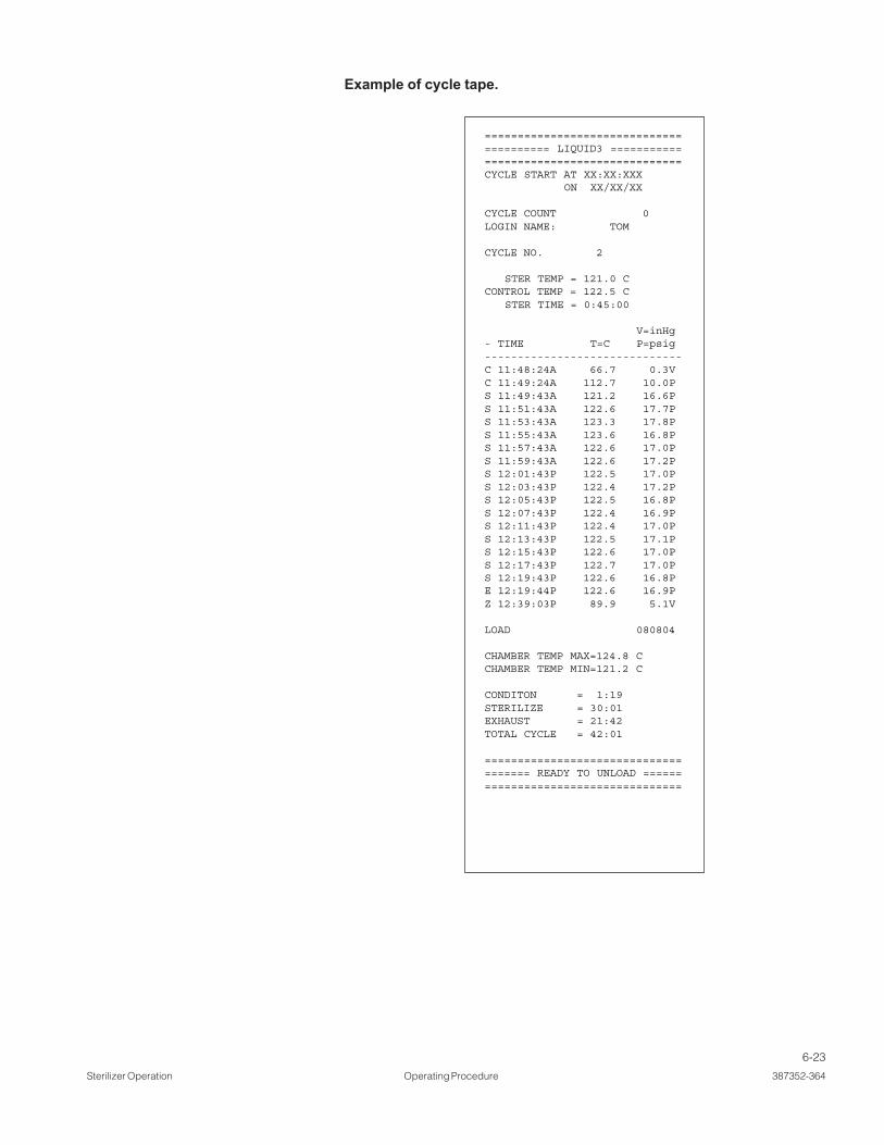
6-23
Sterilizer Operation Operating Procedure 387352-364
======================================== LIQUID3 =========================================CYCLE START AT XX:XX:XXX ON XX/XX/XX
CYCLE COUNT 0LOGIN NAME: TOM
CYCLE NO. 2
STER TEMP = 121.0 CCONTROL TEMP = 122.5 C STER TIME = 0:45:00
V=inHg- TIME T=C P=psig------------------------------C 11:48:24A 66.7 0.3VC 11:49:24A 112.7 10.0PS 11:49:43A 121.2 16.6PS 11:51:43A 122.6 17.7PS 11:53:43A 123.3 17.8PS 11:55:43A 123.6 16.8PS 11:57:43A 122.6 17.0PS 11:59:43A 122.6 17.2PS 12:01:43P 122.5 17.0PS 12:03:43P 122.4 17.2PS 12:05:43P 122.5 16.8PS 12:07:43P 122.4 16.9PS 12:11:43P 122.4 17.0PS 12:13:43P 122.5 17.1PS 12:15:43P 122.6 17.0PS 12:17:43P 122.7 17.0PS 12:19:43P 122.6 16.8PE 12:19:44P 122.6 16.9PZ 12:39:03P 89.9 5.1V
LOAD 080804
CHAMBER TEMP MAX=124.8 CCHAMBER TEMP MIN=121.2 C
CONDITON = 1:19STERILIZE = 30:01EXHAUST = 21:42TOTAL CYCLE = 42:01
===================================== READY TO UNLOAD ====================================
Example of cycle tape.

6-24
387352-364 Operating Procedure Sterilizer Operation
6.5 Isothermal Cycle(Optional)
Carefully review SECTION 1, SAFETY PRECAUTIONS, and below before operatingsterilizer.
WARNING – BURN HAZARD:
• Do not attempt to open the sterilizer door if a WATER IN CHAMBER ALARM condition exists. Call aqualified service technician before attempting to use sterilizer further.
• After manual exhaust, steam may remain inside the chamber. Always wear protective gloves, apron,and a face shield when following emergency procedure to unload sterilizer. Stay as far back from thechamber opening as possible when opening the door.
• Allow sterilizer to cool to room temperature before performing any cleaning or maintenanceprocedures.
• Failure to shut off the steam supply when cleaning or replacing strainers can result in serious injury.
• Jacket pressure must be 0 psig (0 bar) before beginning work on the steam trap.
• Proper testing of the safety valve requires the valve to be operated under pressure. Exhaust from thesafety valve is hot and can cause burns. Proper safety attire (gloves, eye protection, insulated overall)is required. Testing is to be performed by qualified service personnel only.
• When sterilizing liquids, to prevent personal injury or property damage resulting from burstingbottles and hot fluid, you must observe the following procedures:
- Use LIQUID cycle only; no other cycle is safe for processing liquids.
- Use only vented closures; do not use screw caps or rubber stoppers with crimped seal.
- Use only Type 1 borosilicate glass bottles; do not use ordinary glass bottles or any container notdesigned for sterilization.
- Do not allow hot bottles to be jolted; this can cause hot-bottle explosions. Do not move bottles ifany boiling or bubbling is present.
WARNING – EXPLOSION HAZARD: This sterilizer is not designed to process flammable compounds.

6-25
Sterilizer Operation Operating Procedure 387352-364
The cycle is designed for low temperature processing (e.g., fractional steril-ization, pasteurization) at 78 to 110°C (172 to 230°F).
Run an ISOTHERMAL CYCLE by pressing ISOTHERMAL button from isomode operating screen. The screen is shown below:
XX:XX:XX XM
XX/XX/XXXX
The following screen is shown (values are examples only):
Press CANCEL CYCLE button to cancel cycle selected and return tooperating mode screen. Press START CYCLE to start the isothermal cycle. IfCLOSE DOOR(S) button is shown, close door(s). See section on OPERATINGMODE - ISOTHERMAL MODE to change from the STANDARD MODE to ISOMODE.
The following display is shown:
XX:XX:XX XM
XX/XX/XXXX
XX:XX:XX XM
XX/XX/XXXX
Screen #19
Screen #95
Screen #4
ACTIVATE SEAL PHASE: Door gasket seals with steam until doorseal switch is closed. An additional 20 seconds elapses, after sealswitch is closed, before phase is complete. After activate seal phase, thefollowing display is shown:

6-26
387352-364 Operating Procedure Sterilizer Operation
XX:XX:XX XM
XX/XX/XXXX
CHARGE PHASE: Chamber charges with steam until chamber temperaturereaches sterilize temperature. Waste temperature is controlled to maintainapproximately 45.0°C (113.0°F).
After phase is complete, the following screen is shown:
STERILIZE PHASE: Chamber temperature controls at sterilize temperatureplus overdrive. Waste temperature is controlled to maintain approximately45.0°C (113.0°F). After sterilize time is complete,the following screen isshown:
Screen #4
XX:XX:XX XM
XX/XX/XXXXScreen #4
XX:XX:XX XM
XX/XX/XXXXScreen #4
SLOW EXHAUST PHASE: Steam slowly exhausts from chamber to5.0 inHg (0.17 bar). Pressure rate controls at 1.6 psi/minute (0.11 bar) to4.2 psig (0.29 bar) and at 0.6 psi/minute (0.04 bar) to 5.0 inHg (0.17 bar).
After chamber pressure is less than 5.0 inHg (0.17 bar), the followingdisplay is shown:

6-27
Sterilizer Operation Operating Procedure 387352-364
XX:XX:XX XM
XX/XX/XXXX
XX:XX:XX XM
XX/XX/XXXX
VAPOR REMOVAL PHASE: Vapors in chamber vents for 10 minutes.After time is complete, the following screen is shown:
DEACTIVATE SEAL PHASE: Door unseals until seal pressure switchopens and 20 seconds has elapsed.
After phase is complete, the following display is shown:
Screen #4
Screen #4
XX:XX:XX XM
XX/XX/XXXX Screen #4
COMPLETE PHASE: Cycle is complete. Open door and unload chamber.Once door is open, display returns to main operating mode screenshown below:
XX:XX:XX XM
XX/XX/XXXXScreen #19

6-28
387352-364 Operating Procedure Sterilizer Operation
======================================== ISOTHRML ========================================CYCLE START AT XX:XX:XXX ON XX/XX/XX
CYCLE COUNT 0LOGIN NAME: TOM
CYCLE NO. 5
STER TEMP = 104.0 CCONTROL TEMP = 104.0 C STER TIME = 0:45:00
V=inHg- TIME T=C P=psig------------------------------C 11:48:24A 66.7 0.3VC 11:49:24A 112.7 10.0PS 11:49:43A 121.2 16.6PS 11:51:43A 122.6 17.7PS 11:53:43A 123.3 17.8PS 11:55:43A 123.6 16.8PS 11:57:43A 122.6 17.0PS 11:59:43A 122.6 17.2PS 12:01:43P 122.5 17.0PS 12:03:43P 122.4 17.2PS 12:05:43P 122.5 16.8PS 12:07:43P 122.4 16.9PS 12:11:43P 122.4 17.0PS 12:13:43P 122.5 17.1PS 12:15:43P 122.6 17.0PS 12:17:43P 122.7 17.0PS 12:19:43P 122.6 16.8PE 12:19:44P 122.6 16.9PZ 12:39:03P 89.9 5.1V
LOAD 080804
CHAMBER TEMP MAX=124.8 CCHAMBER TEMP MIN=121.2 C
CONDITON = 1:19STERILIZE = 30:01EXHAUST = 21:42TOTAL CYCLE = 42:01
==================================== READY TO UNLOAD =====================================
Example of cycle tape.

6-29
Sterilizer Operation Operating Procedure 387352-364
6.6 Bowie-DickWarmup Cycle (Only
On PrevacuumSterilizers)
Carefully review SECTION 1, SAFETY PRECAUTIONS, and below before operatingsterilizer.
WARNING – BURN HAZARD:
• Do not attempt to open the sterilizer door if a WATER IN CHAMBER ALARM condition exists. Call aqualified service technician before attempting to use sterilizer further.
• After manual exhaust, steam may remain inside the chamber. Always wear protective gloves, apron,and a face shield when following emergency procedure to unload sterilizer. Stay as far back from thechamber opening as possible when opening the door.
• Allow sterilizer to cool to room temperature before performing any cleaning or maintenanceprocedures.
• Failure to shut off the steam supply when cleaning or replacing strainers can result in serious injury.
• Jacket pressure must be 0 psig (0 bar) before beginning work on the steam trap.
• Proper testing of the safety valve requires the valve to be operated under pressure. Exhaust from thesafety valve is hot and can cause burns. Proper safety attire (gloves, eye protection, insulated overall)is required. Testing is to be performed by qualified service personnel only.
• When sterilizing liquids, to prevent personal injury or property damage resulting from burstingbottles and hot fluid, you must observe the following procedures:
- Use LIQUID cycle only; no other cycle is safe for processing liquids.
- Use only vented closures; do not use screw caps or rubber stoppers with crimped seal.
- Use only Type 1 borosilicate glass bottles; do not use ordinary glass bottles or any container notdesigned for sterilization.
- Do not allow hot bottles to be jolted; this can cause hot-bottle explosions. Do not move bottles ifany boiling or bubbling is present.
WARNING – EXPLOSION HAZARD: This sterilizer is not designed to process flammable compounds.

6-30
387352-364 Operating Procedure Sterilizer Operation
The cycle is used to warm up sterilizer shelves, door, and jacket before aDART (Bowie-Dick) cycle is run.
Run a DART WARMUP CYCLE by pressing BOWIE-DICK WARMUP buttonfrom the following screen.
This screen is obtained by pressing TEST MODE button on screen #2 orscreen #19. The following display is shown:
XX:XX:XX XM
XX/XX/XXXX
JACKET CHARGE PHASE: Jacket charge phase continues until jackettemperature is greater than 132.0°C (270.0°F). After jacket charge phase, thefollowing display appears:
ACTIVATE SEAL PHASE: Door gasket seals with steam until door seal switchis closed. An additional 20 seconds elapses, after seal switch is closed,before phase is complete. After activate seal phase, the following displayappears:
XX:XX:XX XM
XX/XX/XXXX
XX:XX:XX XM
XX/XX/XXXX
Screen #23
Screen #4
Screen #4
Bowie-DickWarmup Cycle

6-31
Sterilizer Operation Operating Procedure 387352-364
PURGE PHASE: Steam enters chamber from jacket to control pressureat 6 psig. Fast exhaust and water ejector is on to aid in removing air fromchamber. After purge time, the following display appears:
XX:XX:XX XM
XX/XX/XXXX
CHARGE PHASE: Chamber charges with steam until chamber temperaturereaches sterilize temperature. Waste temperature is controlled to maintainapproximately 45.0°C (113.0°F). After phase is complete, the followingscreen appears:
STERILIZE PHASE: Chamber temperature controls at sterilize temperatureplus overdrive (control temperature). Waste temperature is controlled tomaintain approximately 45.0° C (113.0° F). After sterilize time is complete, thefollowing screen appears:
XX:XX:XX XM
XX/XX/XXXX
XX:XX:XX XM
XX/XX/XXXX
Screen #4
Screen #4
Screen #4

6-32
387352-364 Operating Procedure Sterilizer Operation
FAST EXHAUST PHASE: Steam fast exhausts from chamber to 4.0 psig(0.28 bar). After chamber pressure is less than 4.0 psig (0.28 bar), thefollowing display appears:
VACUUM DRY PHASE: A vacuum is pulled in chamber to 10.0 inHg(-0.34 bar) (VACUUM DRY setpoint). After chamber pressure is less than10.0 inHg (-0.34 bar), the following display appears:
DRY PHASE: During dry phase, vacuum continues to be pulled to limit ofsystem for dry time. After dry time, the following screen appears:
XX:XX:XX XM
XX/XX/XXXX
XX:XX:XX XM
XX/XX/XXXX
XX:XX:XX XM
XX/XX/XXXX
Screen #4
Screen #4
Screen #4

6-33
Sterilizer Operation Operating Procedure 387352-364
AIR BREAK PHASE: Chamber vacuum air breaks to 2.0 inHg (-0.17 bar).After chamber pressure is above 2.0 inHg (-0.17 bar), the following screenappears:
DEACTIVATE SEAL PHASE: Door unseals until seal pressure switch opensand 20 seconds has elapsed. After phase is complete, the followingdisplay appears:
COMPLETE PHASE: Cycle is complete. Open door and unload chamber.Once door is open, display returns to main operating mode screen shownbelow:
XX:XX:XX XM
XX/XX/XXXX
XX:XX:XX XM
XX/XX/XXXX
XX:XX:XX XM
XX/XX/XXXX
Screen #4
Screen #4
Screen #23
XX:XX:XX XM
XX/XX/XXXXScreen #4
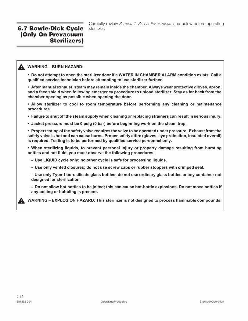
6-34
387352-364 Operating Procedure Sterilizer Operation
6.7 Bowie-Dick Cycle(Only On Prevacuum
Sterilizers)
Carefully review SECTION 1, SAFETY PRECAUTIONS, and below before operatingsterilizer.
WARNING – BURN HAZARD:
• Do not attempt to open the sterilizer door if a WATER IN CHAMBER ALARM condition exists. Call aqualified service technician before attempting to use sterilizer further.
• After manual exhaust, steam may remain inside the chamber. Always wear protective gloves, apron,and a face shield when following emergency procedure to unload sterilizer. Stay as far back from thechamber opening as possible when opening the door.
• Allow sterilizer to cool to room temperature before performing any cleaning or maintenanceprocedures.
• Failure to shut off the steam supply when cleaning or replacing strainers can result in serious injury.
• Jacket pressure must be 0 psig (0 bar) before beginning work on the steam trap.
• Proper testing of the safety valve requires the valve to be operated under pressure. Exhaust from thesafety valve is hot and can cause burns. Proper safety attire (gloves, eye protection, insulated overall)is required. Testing is to be performed by qualified service personnel only.
• When sterilizing liquids, to prevent personal injury or property damage resulting from burstingbottles and hot fluid, you must observe the following procedures:
- Use LIQUID cycle only; no other cycle is safe for processing liquids.
- Use only vented closures; do not use screw caps or rubber stoppers with crimped seal.
- Use only Type 1 borosilicate glass bottles; do not use ordinary glass bottles or any container notdesigned for sterilization.
- Do not allow hot bottles to be jolted; this can cause hot-bottle explosions. Do not move bottles ifany boiling or bubbling is present.
WARNING – EXPLOSION HAZARD: This sterilizer is not designed to process flammable compounds.

6-35
Sterilizer Operation Operating Procedure 387352-364
The cycle is designed to document the removal of residual air from a samplechallenge load.
Run a BOWIE-DICK CYCLE by pressing B+D CYCLE button from the followingscreen:
This screen is obtained by pressing the button on screen #2 or screen #19.The following display appears (see SECTION 5.3, STATUS BUTTONS, for descriptionof buttons):
JACKET CHARGE PHASE: Jacket charge phase continues until jackettemperature is greater than 132.0°C (270.0°F). After jacket charge phase, thefollowing display appears:
XX:XX:XX XM
XX/XX/XXXX
XX:XX:XX XM
XX/XX/XXXX
XX:XX:XX XM
XX/XX/XXXX
Screen #23
Screen #4
Screen #4
ACTIVATE SEAL PHASE: Door gasket seals with steam until door seal switchis closed. An additional 20 seconds elapses, after seal switch is closed, before phase is complete. After the activate seal phase, the following displayappears:
Bowie-DickCycle Button

6-36
387352-364 Operating Procedure Sterilizer Operation
PURGE PHASE: Steam enters chamber from jacket to control pressure at6 psig. Fast exhaust and water ejector is on to aid in removing air fromchamber. After purge time, the following display appears:
PULSE EXHAUST PHASE: Chamber exhausts to 4.0 psig (0.28 bar). Wastetemperature is controlled to maintain approximately 45.0°C (113.0°F).Jacket temperature is controlled to maintain approximately 133.5°C(273.0°F) in jacket. After phase is complete, the following screen appears:
PULSE EVACUATE PHASE: Chamber evacuates to PULSE VACUUMsetpoint (default 10.0 inHg (-0.34 bar) plus one minute. Waste temperatureis controlled to maintain approximately 45.0°C (113.0°F). Jacket temperatureis controlled to maintain approximately 133.5°C (273.0°F) in jacket. Afterphase is complete, the following screen appears:
XX:XX:XX XM
XX/XX/XXXX
XX:XX:XX XM
XX/XX/XXXX
XX:XX:XX XM
XX/XX/XXXX
Screen #4
Screen #4
Screen #4

6-37
Sterilizer Operation Operating Procedure 387352-364
PULSE CHARGE PHASE: Chamber charges with steam to PULSE CHARGEsetpoint (default 26.0 psig (0.34 bar). PULSE EXHAUST, PULSE EVACUATE,and PULSE CHARGE repeat for the number of pulses selected. After lastPULSE EVACUATE phase is complete, the following screen appears:
CHARGE PHASE: Chamber charges with steam until chamber temperaturereaches sterilize temperature. Waste temperature is controlled to maintainapproximately 45.0°C (113.0°F). After phase is complete, the following screenappears:
XX:XX:XX XM
XX/XX/XXXX
XX:XX:XX XM
XX/XX/XXXX
XX:XX:XX XM
XX/XX/XXXX
Screen #4
Screen #4
Screen #4
STERILIZE PHASE: Chamber temperature controls at sterilize temperatureplus overdrive (control temperature). Waste temperature is controlled tomaintain approximately 45.0°C (113.0°F). After sterilize time is complete, thefollowing screen appears:

6-38
387352-364 Operating Procedure Sterilizer Operation
FAST EXHAUST PHASE: Steam fast exhausts from chamber to 4.0 psig(0.28 bar). After chamber pressure is less than 4.0 psig (0.28 bar), thefollowing display appears:
VACUUM DRY PHASE: A vacuum is pulled in the chamber to 10.0 inHg(- 0.34 bar) (VACUUM DRY setpoint). After chamber pressure is less than10.0 inHg (-0.34 bar), the following display appears:
DRY PHASE: During dry phase, vacuum continues to be pulled to limit ofsystem for dry time. After dry time, the following screen appears:
XX:XX:XX XM
XX/XX/XXXX
XX:XX:XX XM
XX/XX/XXXX
XX:XX:XX XM
XX/XX/XXXX
Screen #4
Screen #4
Screen #4

6-39
Sterilizer Operation Operating Procedure 387352-364
AIR BREAK PHASE: Chamber vacuum air breaks to 2.0 inHg (-0.17 bar).After chamber pressure is above 2.0 inHg (-0.17 bar), the following screenappears:
DEACTIVATE SEAL PHASE: Door unseals until seal pressure switch opensand 20 seconds has elapsed. After phase is complete, the followingdisplay appears:
XX:XX:XX XM
XX/XX/XXXX
XX:XX:XX XM
XX/XX/XXXX
COMPLETE PHASE: Cycle is complete. Open door and unload chamber.Once door is open, display returns to main operating mode screen shownbelow:
XX:XX:XX XM
XX/XX/XXXX
XX:XX:XX XM
XX/XX/XXXX
Screen #4
Screen #4
Screen #4
Screen #23

6-40
387352-364 Operating Procedure Sterilizer Operation
6.8 Leak Test Cycle(Only On Prevacuum
Sterilizers)
Carefully review SECTION 1, SAFETY PRECAUTIONS, and below before operatingsterilizer.
WARNING – BURN HAZARD:
• Do not attempt to open the sterilizer door if a WATER IN CHAMBER ALARM condition exists. Call aqualified service technician before attempting to use sterilizer further.
• After manual exhaust, steam may remain inside the chamber. Always wear protective gloves, apron,and a face shield when following emergency procedure to unload sterilizer. Stay as far back from thechamber opening as possible when opening the door.
• Allow sterilizer to cool to room temperature before performing any cleaning or maintenanceprocedures.
• Failure to shut off the steam supply when cleaning or replacing strainers can result in serious injury.
• Jacket pressure must be 0 psig (0 bar) before beginning work on the steam trap.
• Proper testing of the safety valve requires the valve to be operated under pressure. Exhaust from thesafety valve is hot and can cause burns. Proper safety attire (gloves, eye protection, insulated overall)is required. Testing is to be performed by qualified service personnel only.
• When sterilizing liquids, to prevent personal injury or property damage resulting from burstingbottles and hot fluid, you must observe the following procedures:
- Use LIQUID cycle only; no other cycle is safe for processing liquids.
- Use only vented closures; do not use screw caps or rubber stoppers with crimped seal.
- Use only Type 1 borosilicate glass bottles; do not use ordinary glass bottles or any container notdesigned for sterilization.
- Do not allow hot bottles to be jolted; this can cause hot-bottle explosions. Do not move bottles ifany boiling or bubbling is present.
WARNING – EXPLOSION HAZARD: This sterilizer is not designed to process flammable compounds.

6-41
Sterilizer Operation Operating Procedure 387352-364
Important: Before running a leak test cycle, the chamber temperature shouldbe stabilized by running a normal cycle. A leak test cycle should be run on thesterilizer at least once each week. It should be one of the first cycles run for theday, but not the first cycle. In this cycle, the sterilizer automatically checks forvacuum leaks in the piping and door seal. If the sterilizer fails the leak test, itmust be inspected by a service technician before using the sterilizer further.The leak test can be used to confirm that the sterilizer piping is intact afterperforming repairs.
NOTE: This test is not a substitute for a Dart test.
NOTE: The measured leak rate (mmHg/minute) is calculated by the controlover a timed 10 minute period and is included in the cycle printout. A leak rateof 1 mmHg/minute is considered acceptable.
Run a LEAK TEST CYCLE by pressing LEAK TEST button from the followingscreen.
This screen is obtained by pressing TEST MODE button on screen #2 orscreen #19. The following display is shown:::::
JACKET CHARGE PHASE: Jacket charge phase continues until jackettemperature is greater than 132.0°C (270.0°F). After jacket charge phase, thefollowing display appears:
XX:XX:XX XM
XX/XX/XXXX
XX:XX:XX XM
XX/XX/XXXX
Screen #23
Screen #4
Leak TestButton
XX:XX:XX XM
XX/XX/XXXXScreen #4

6-42
387352-364 Operating Procedure Sterilizer Operation
PURGE PHASE: Steam enters chamber from jacket to control pressure at6 psig. Fast exhaust and water ejector is on to aid in removing air fromchamber. After purge time, the following display appears:
PULSE EXHAUST PHASE: Chamber exhausts to 4.0 psig (0.28 bar). Wastetemperature is controlled to maintain approximately 45.0°C (113.0°F). Jackettemperature is controlled to maintain approximately 133.5°C (273.0°F) injacket. After phase is complete, the following screen appears:
XX:XX:XX XM
XX/XX/XXXX
XX:XX:XX XM
XX/XX/XXXX
ACTIVATE SEAL PHASE: Door gasket seals with steam until door sealswitch is closed. An additional 20 seconds elapses, after seal switch is closed,before phase is complete. After activate seal phase, the following displayappears:
Screen #4
Screen #4

6-43
Sterilizer Operation Operating Procedure 387352-364
PULSE CHARGE PHASE: Chamber charges with steam to PULSE CHARGEsetpoint (default 26.0 psig (0.34 bar). PULSE EXHAUST, PULSE EVACUATE,and PULSE CHARGE repeat for the number of pulses selected. After lastPULSE EVACUATE phase is complete, the following screen appears:
EVACUATE PHASE: Chamber evacuates for 10 minutes. Waste temperatureis controlled to maintain approximately 45.0°C (113.0°F). After phase iscomplete, the following screen appears:
XX:XX:XX XM
XX/XX/XXXX
XX:XX:XX XM
XX/XX/XXXX
Screen #4
Screen #4
PULSE EVACUATE PHASE: Chamber evacuates to PULSE VACUUMsetpoint (default 10.0 inHg (-0.34 bar). Waste temperature is controlled tomaintain approximately 45.0°C (113.0°F). Jacket temperature is controlled tomaintain approximately 133.5°C (273.0°F) in jacket. After phase is complete,the following screen appears:
XX:XX:XX XM
XX/XX/XXXXScreen #4

6-44
387352-364 Operating Procedure Sterilizer Operation
LEAK TEST PHASE: Chamber holds for 10 minutes. Initial and final pressurevalues are recorded. Leak rate is determined in mmHg. After leak test timeis complete, the following display appears:
AIR BREAK PHASE: Chamber vacuum air breaks to 2.0 inHg (-0.17 bar).After chamber pressure is above 2.0 inHg (-0.17 bar), the following screenappears:
STABILIZE PHASE: Chamber remains in an idle state for two minutes (i.e.,chamber holds at vacuum level). Waste temperature is controlled tomaintain approximately 45.0°C (113.0°F). After stabilize time is complete, thefollowing screen appears:
XX:XX:XX XM
XX/XX/XXXXScreen #4
XX:XX:XX XM
XX/XX/XXXXScreen #4
XX:XX:XX XM
XX/XX/XXXXScreen #4

6-45
Sterilizer Operation Operating Procedure 387352-364
COMPLETE PHASE: The cycle is complete. Open the door. Once door isopen, display returns to main operating mode screen shown below:
XX:XX:XX XM
XX/XX/XXXXScreen #4
DEACTIVATE SEAL PHASE: Door unseals until seal pressure switch opensand 20 seconds has elapsed. After phase is complete, the following displayappears:
XX:XX:XX XM
XX/XX/XXXXScreen #4
XX:XX:XX XM
XX/XX/XXXXScreen #23

6-46
387352-364 Operating Procedure Sterilizer Operation
6.9 Cycle AbortThe cycle may abort for two reasons. The operator pressed the abort buttonor the cycle got an alarm that aborted the cycle. The following display is anexample screen when the cycle is aborted.
If the operator aborted the cycle, the printer prints
The cycle aborts to the fast exhaust or slow exhaust phase. If the purge phasehasn’t been run yet, cycle aborts to the deactivate seal phase.
If ABORT button is pressed on screen #64, the cycle ends and the screenshows operating mode screen #2 or #19. Cycle relieves any pressure inchamber.
XX:XX:XX XM
XX/XX/XXXX
* CYCLE ABORTED BY OPERATOR
Screen #64

6-47
Sterilizer Operation Operating Procedure 387352-364
If the sterilizer is equipped with double doors, there is an indicator light andunseal door button on the non-operating end door panel. The operating enddoor panel is provided with an unseal button on the display.
The indicator light is lit during cycle progress. The indicator is also lit whenever the door may not be unsealed. When the door is sealed, but may be unsealed,the indicator light blinks. Once the door is unsealed, the light turns off.
Press UNSEAL DOOR button to unseal door. Close door when completedloading or unloading chamber. Door automatically seals when operating dooris unsealed.
See SECTION 6.12.1, SUPERVISOR MODE - CYCLE PARAMETERS, on thedescription of the interlock types.
The load probe and Fo option equips the sterilizer with a load temperatureprobe (RTD) sealed through the chamber vessel. The probe is manuallylocated by the operator in the product container within the chamber. Inconjunction with this load probe option, the microcomputer control allowsoperator selection of two sterilization time measurement control modes.These modes are labeled: STER CTRL=DRAIN and STER CTRL=LOAD.
The DRAIN or standard time at temperature mode selection allows exposuretime to be started from the temperature probe (RTD) located in the chamberdrain line. Exposure time starts when drain line temperature is equal to orgreater than chamber temperature setpoint, regardless of load temperature.
The LOAD or equivalent time at sterilization temperature mode selectionallows exposure time to start when load probe located in the product and thechamber drain line probe reach a pre-set sterilize temperature. The Fo valueis calculated from the load probe located in the product load. Charge orexposure phase terminates when calculated Fo value is equal to the pre-selected value, or if the sterilize time counts down to 0, whichever occurs first.The Fo value and load temperature are printed along with standard status printvalues.
The Fo is the measure of equivalent time at which a specific load would havebeen exposed at the base sterilization temperature of 121.0° C (250.0° F).Units of Fo are minutes. The sterilizer control is programmed to calculate Fo
once all load probes have reached 110.0°C (230.0°F), although significant Fo
accumulation does not occur until all load probes are above 121.0°C (250.0°F),Fo accumulates faster than real (clock) minutes.
The formula for Fo is Fo = Σ(10[(t1-t2)/Z]) * ∆t
Where: t1 = Load temperature
t2 = 121.0° C (250.0° F)
Z = 10.0° C (18.0° F)
∆t = 1/60 minute (the time duration between Fo accumulations per 1 minute
See SECTION 6.12.1, CYCLE PARAMETERS, on the description of changing Fo andSTER CTRL values.
6.10 Double Doors
6.11 Load Probe andFo Sterilization
(Sterilizers With LoadProbe Only)
6.11.1 Fo Sterilization

6-48
387352-364 Operating Procedure Sterilizer Operation
6.13 SupervisorMode
Refer to SECTION 5, CONTROL INTERFACE, for instructions on how to get toscreen #6. The supervisor mode may be entered by pressingSUPERVISOR button on screen #6.
The following display is shown:
XX:XX:XX XM
XX/XX/XXXX
Press CYCLE PARAMETERS on screen #7 to change or view cycle param-eters. The following display is shown (gravity sterilizer):
XX:XX:XX XM
XX/XX/XXXX
6.13.1 Cycle Parameters
Press PRINT CYCLE VALUES button to print all of the cycle parameters. Thefollowing page shows an example print with defaulted cycle values for aprevac sterilizer.
XX:XX:XX XM
XX/XX/XXXX
Screen #6
Screen #7
Screen #10
The separate steam feed option directs steam to jacket, while directing steamto chamber separately. The default method is to allow chamber steam to befed from the jacket.
The separate steam feed option allows jacket temperature to be controlledindependently from chamber temperature. Jacket temperature can be set foreach individual cycle (see SECTION 6.13.1, CYCLE PARAMETERS).
6.12 Separate SteamFeed Option

6-49
Sterilizer Operation Operating Procedure 387352-364
VAC DRY = 10.0 inHg DRY TIME = 0:15:00STRL CTRL = DRAIN Fo = 0------------------------------5.GRAVITY5PURGE TIME= 2:00STER TIME = 0:30:00STER TEMP = 121.0°C OVERTEMP = 6.0°COVERDRIVE = 1.5 CUNDERTEMP = 1.0°C RESUMEPRINT INT = 2 MIN VAC DRY = 10.0 inHg DRY TIME = 0:15:00STRL CTRL = DRAIN Fo = 0------------------------------6.GRAVITY6PURGE TIME= 2:00STER TIME = 0:30:00STER TEMP = 121.0°C OVERTEMP = 6.0°COVERDRIVE = 1.5 CUNDERTEMP = 1.0°C RESUMEPRINT INT = 2 MIN VAC DRY = 10.0 inHg DRY TIME = 0:15:00STRL CTRL = DRAIN Fo = 0------------------------------7.LIQUID7PURGE TIME= 2:00STER TIME = 0:45:00STER TEMP = 121.0°C OVERTEMP = 6.0°COVERDRIVE = 1.5 CUNDERTEMP = 1.0°C RESUMEPRINT INT = 2 MINSTRL CTRL = DRAIN Fo = 0------------------------------8.LIQUID8PURGE TIME= 2:00STER TIME = 0:45:00STER TEMP = 121.0°C OVERTEMP = 6.0°COVERDRIVE = 1.5 CUNDERTEMP = 1.0°C RESUMEPRINT INT = 2 MINSTRL CTRL = DRAIN Fo = 0------------------------------
TOO LONG IN:------------------------------ACTIVATE SEAL = 1 m AIR BREAK = 5 m CHARGE = 60 mDEACTIVATE SEAL= 1 m EVACUATE = 30 m EXHAUST = 10 m JACKET CHARGE = 60 m
================================== CYCLE VALUES PRINTOUT =================================XX:XX:XX XM XX/XX/XX
LOGIN NAME: STERIS
1.PREVAC1PURGE TIME= 2:00 PULSES = 4 PRES VAC = 10.0 inHg PRES CHG = 15.0 PSIGSTER TIME = 0:30:00STER TEMP = 121.0°C OVERTEMP = 6.0°COVERDRIVE = 1.5 CUNDERTEMP = 1.0°C RESUMEPRINT INT = 2 MIN VAC DRY = 10.0 inHg DRY TIME = 0:15:00STRL CTRL = DRAIN Fo = 0------------------------------2.PREVAC2PURGE TIME= 2:00 PULSES = 4 PRES VAC = 10.0 inHg PRES CHG = 15.0 PSIGSTER TIME = 0:30:00STER TEMP = 121.0°C OVERTEMP = 6.0°COVERDRIVE = 1.5 CUNDERTEMP = 1.0°C RESUMEPRINT INT = 2 MIN VAC DRY = 10.0 inHg DRY TIME = 0:15:00STRL CTRL = DRAIN Fo = 0------------------------------3.PREVAC3PURGE TIME= 2:00 PULSES = 4 PRES VAC = 10.0 inHg PRES CHG = 15.0 PSIGSTER TIME = 0:30:00STER TEMP = 121.0°C OVERTEMP = 6.0°COVERDRIVE = 1.5 CUNDERTEMP = 1.0°C RESUMEPRINT INT = 2 MIN VAC DRY = 10.0 inHg DRY TIME = 0:15:00STRL CTRL = DRAIN Fo = 0------------------------------4.PREVAC4PURGE TIME= 2:00 PULSES = 4 PRES VAC = 10.0 inHg PRES CHG = 15.0 PSIGSTER TIME = 0:30:00STER TEMP = 121.0°C OVERTEMP = 6.0°COVERDRIVE = 1.5 CUNDERTEMP = 1.0°C RESUMEPRINT INT = 2 MIN

6-50
387352-364 Operating Procedure Sterilizer Operation
Screen #10 shows cycles 1 through 4. These cycles may be any combinationof PREVAC, GRAVITY or LIQUID cycle type.
Press RIGHT ARROW button to change cycles 5 through 8. These cycles areshown on screen #36.
Press LEFT ARROW button to go back to screen #10. Press GRAVITY buttonto change cycle values on cycle 1 (NOTE: This procedure may be applied forany cycle – some cycles may have less or more parameters). The display thenshows:
XX:XX:XX XM
XX/XX/XXXX
Values for cycle 1 may be changed on screen #28. Press GRAVITY buttonto change cycle type (either GRAVITY or LIQUID). On prevac machines,PREVAC button is shown. The following display is shown:
XX:XX:XX XM
XX/XX/XXXX
Press LIQUID button to set cycle to a liquid cycle type. Press GRAVITYbutton to set cycle to a gravity cycle type. On prevac sterilizers, pressPREVAC button to set cycle to a prevac cycle type. The selected cycletype is shown on screen #28 or #32 for prevac cycles.
XX:XX:XX XM
XX/XX/XXXX
Screen #36
Screen #28
Screen #5
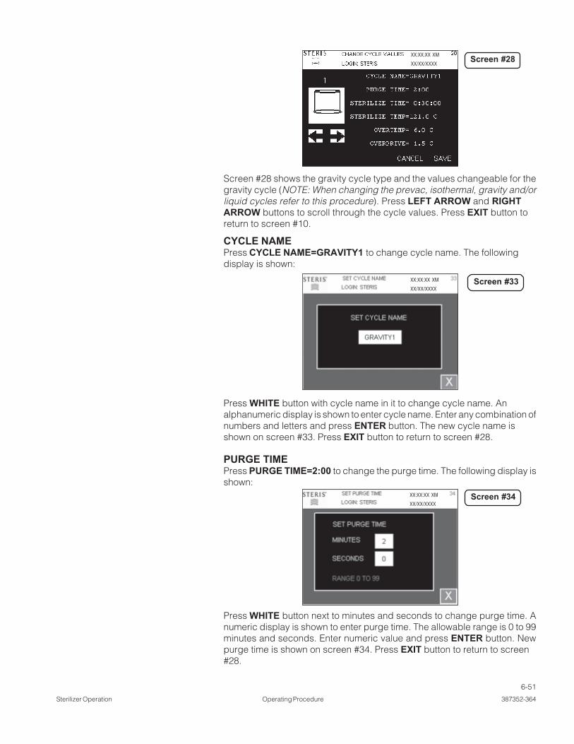
6-51
Sterilizer Operation Operating Procedure 387352-364
Screen #28 shows the gravity cycle type and the values changeable for thegravity cycle (NOTE: When changing the prevac, isothermal, gravity and/orliquid cycles refer to this procedure). Press LEFT ARROW and RIGHTARROW buttons to scroll through the cycle values. Press EXIT button toreturn to screen #10.
CYCLE NAMEPress CYCLE NAME=GRAVITY1 to change cycle name. The followingdisplay is shown:
XX:XX:XX XM
XX/XX/XXXX
Press WHITE button with cycle name in it to change cycle name. Analphanumeric display is shown to enter cycle name. Enter any combination ofnumbers and letters and press ENTER button. The new cycle name isshown on screen #33. Press EXIT button to return to screen #28.
PURGE TIMEPress PURGE TIME=2:00 to change the purge time. The following display isshown:
XX:XX:XX XM
XX/XX/XXXX
XX:XX:XX XM
XX/XX/XXXX
Press WHITE button next to minutes and seconds to change purge time. Anumeric display is shown to enter purge time. The allowable range is 0 to 99minutes and seconds. Enter numeric value and press ENTER button. Newpurge time is shown on screen #34. Press EXIT button to return to screen#28.
Screen #28
Screen #33
Screen #34

6-52
387352-364 Operating Procedure Sterilizer Operation
PULSES (only on Prevacuum sterilizers)Press PULSES=4 to change number of pulses. The following display isshown:
Press WHITE button to change number of pulses. A numeric display is shownto enter pulses. The allowable range is 0 to 99. Enter numeric value and pressENTER button. New pulses are shown on screen #49. Press EXITbutton to return to screen #32.
PULSE VACUUM (only on Prevacuum sterilizers)Press PULSE VACUUM=10.0 to change pulse vacuum value. Thefollowing display is shown:
XX:XX:XX XM
XX/XX/XXXX
Press WHITE button to change the pulse vacuum. A numeric display is shownto enter pulse vacuum. The allowable range is 0 to 29.0 inHg. Enter numericvalue and press ENTER button. New pulse vacuum is shown on screen#50. Press EXIT button to return to screen #32.
PULSE CHARGE (only on Prevacuum sterilizers)Press PULSE CHARGE=15.0 to change pulse charge value. The followingdisplay is shown:
XX:XX:XX XM
XX/XX/XXXX
XX:XX:XX XM
XX/XX/XXXX
Screen #49
Screen #50
Screen #51

6-53
Sterilizer Operation Operating Procedure 387352-364
Press WHITE button to change pulse charge. A numeric display is shown toenter pulse charge. The allowable range is 0 to 35.0 psig. Enter numeric valueand press ENTER button. New pulse charge is shown on screen #51. PressEXIT button to return to screen #32.
STERILIZE TIMEPress STERILIZE TIME=0:30:00 to change sterilize time. The followingdisplay is shown:
XX:XX:XX XM
XX/XX/XXXX
Press WHITE button next to the hours, minutes and seconds to changesterilize time. A numeric display is shown to enter sterilize time. The allowablerange is 0 to 99 hours, minutes, and seconds. Enter numeric value and pressENTER button. New sterilize time is shown on screen #35. Press EXIT buttonto return to screen #28.
STERILIZE TEMPERATUREPress STERILIZE TEMPERATURE=121.0°C to change sterilize tempera-ture. The following display is shown:
XX:XX:XX XM
XX/XX/XXXX
Press WHITE button to change sterilize temperature. A numeric display isshown to enter sterilize temperature. The allowable range is 100.0°C (212.0°F)to 141.0°C (285.0°F) for prevac, gravity, and liquid cycles. The allowablerange is 78.0°C (172.0°F) to 110.0°C (230.0°F) for isothermal cycles. Enternumeric value and press ENTER button. New sterilize temperature isshown on screen #38. Press EXIT button to return to screen #28.
Screen #35
Screen #38

6-54
387352-364 Operating Procedure Sterilizer Operation
OVERTEMPPress OVERTEMP=6.0°C to change over temperature alarm setpoint. SeeSECTION 7, ALARMS, for explanation of over temperature alarm. The followingdisplay is shown:
Press WHITE button to change overtemp. A numeric display is shown toenter overtemp. The allowable range is 0.0°C (32.0°F) to 40.0°C (104.0°F).Enter numeric value and press ENTER button. New sterilize temperature isshown on screen #39. Press EXIT button to return to screen #28.
OVERDRIVEPress OVERDRIVE=1.5°C to change overdrive (sterilize temperature + over-drive = control temperature). See sterilize phase in cycle for an explanation ofcontrol temperature. The following display is shown:
XX:XX:XX XM
XX/XX/XXXX
Press WHITE button to change overdrive. A numeric display is shown toenter overdrive. The allowable range is 0.0°C (32.0°F) to 40.0°C (104.0°F).Enter numeric value and press ENTER button. The new sterilize temperatureis shown on screen #40. Press EXIT button to return to screen #28.
XX:XX:XX XM
XX/XX/XXXX
Screen #39
Screen #40

6-55
Sterilizer Operation Operating Procedure 387352-364
UNDERTEMPPress UNDERTEMP=1.0°C to change under temperature alarm setpoint. SeeALARM SECTION for explanation of under temperature alarm. The followingdisplay is shown:
Press WHITE button to change undertemp. A numeric display is shown to enterundertemp. The allowable range is 0.0°C (32.0°F) to 40.0°C (104.0°F). Enternumeric value and press ENTER button. New sterilize temperature is shown onscreen #41. Press EXIT button to return to screen #28.
PRINT INTERVALPress PRINT INT=2 MIN to change the print interval setpoint. Print interval isthe time interval of the status prints during sterilize phase. The followingdisplay is shown:
XX:XX:XX XM
XX/XX/XXXX
XX:XX:XX XM
XX/XX/XXXX
Press WHITE button to change print interval. A numeric display is shown toenter print interval. The allowable range is 0 to 99 minutes. Enter numeric valueand press ENTER button. New sterilize temperature is shown on screen #42.Press EXIT button to return to screen #28.
Screen #41
Screen #42

6-56
387352-364 Operating Procedure Sterilizer Operation
DRY TIMEPress DRY TIME=0:15:00 to change the dry time. The following display isshown:
XX:XX:XX XM
XX/XX/XXXXScreen #44
RESUME/RESTARTPress RESUME/RESTART=RESUME to set resume or restart setting. RE-SUME resumes sterilize timer after it has been stopped on an under tempera-ture alarm. RESTART restarts sterilize timer after is has been stopped on anunder temperature alarm. The following display is shown:
XX:XX:XX XM
XX/XX/XXXX
Press either RESUME or RESTART buttons to resume or restart. New resumeor restart setting is shown on screen #28.
VACUUM DRYPress VACUUM DRY=10.0 inHg (-0.34 bar) to change vacuum dry setpoint.Vacuum dry setpoint is the vacuum level that dry timer starts. The followingdisplay is shown:
XX:XX:XX XM
XX/XX/XXXX
Press WHITE button to change vacuum dry setting. A numeric display isshown to enter vacuum dry setting. The allowable range is 0.0 to 29.9 inHg(1.0 -bar). Enter numeric value and press ENTER button. New vacuum drysetting is shown on screen #43. Press EXIT button to return to screen #28.
Screen #45
Screen #43

6-57
Sterilizer Operation Operating Procedure 387352-364
Press white button to change jacket temperature. A numeric display appearsto enter jacket temperature. The allowable range is 100 to 141.0°C. The newjacket temperature is shown on screen #39. Press exit button to return toscreen #35.
STER CTRL (LOAD PROBE OPTION)Press STER CTRL=DRAIN to set which temperatures the control uses totransition to sterilize phase. DRAIN option enters sterilize phase when cham-ber temperature reaches sterilize temperature. LOAD option enters sterilizephase when chamber and load temperature reaches sterilize temperature.Selecting LOAD option also enables Fo (See Fo cycle value). The followingdisplay is shown:
Press either LOAD or DRAIN buttons to resume or restart. New resume orrestart setting is shown on screen #28.
XX:XX:XX XM
XX/XX/XXXX
Fo (LOAD PROBE OPTION)Press Fo=0.0 to change the Fo value. Charge or sterilize phase ends whenactual Fo value is equal to or greater than this setting. The following display isshown:
Screen #68
Press WHITE button next to the hours, minutes, and seconds to change thedry time. A numeric display is shown to enter dry time. The allowable range is0 to 99 hours, minutes, and seconds. Enter any numeric value and pressENTER button. New dry time is shown on screen #44. Press EXIT button toreturn to screen #32.
JACKET TEMPERATURE (SEPARATE STEAM OPTION, ONLY)Press JACKET TEMPERATURE = 115.0°C to change the jacket temperature.The following display appears:
Screen #39XX:XX:XX XM
XX/XX/XXXX

6-58
387352-364 Operating Procedure Sterilizer Operation
Press WHITE button to change Fo setting. A numeric display is shown toenter Fo setting. Enter numeric value and press ENTER button. New vacuumdry setting is shown on screen #69. Press EXIT button to return to screen #28.
XX:XX:XX XM
XX/XX/XXXX
INTERLOCK DOORS (double door sterilizers only)Press INTERLOCK = DOOR B button to change interlock type. The followingdisplay is shown:
There are four interlock types:
1. NO INTERLOCKS – Selected on screen above. Both doors are unsealedat the end of the cycle. Either door may be sealed or unsealed as manytimes as needed, out of cycle.
2. SELECT DOOR TO UNSEAL – At the end of the cycle, both doors remainsealed. Press unseal door button on same side as door to be unsealed.Door B is designated as the sterile side. Once door A is unsealed, doorB may not be unsealed until a cycle is run.
3. DOOR A UNSEALED – At the end of the cycle, door A is unsealed. Pressunseal door button on door A. Door B is designated as the sterile side.Once door A is unsealed, door B may not be unsealed until a cycle is run.
4. DOOR B UNSEALED – At the end of the cycle, door B is unsealed. Pressunseal door button on door A. The door B is designated as the sterile side.Once door A is unsealed, door B may not be unsealed until a cycle is run.
From SUPERVISOR MODE screen #7, press TOO LONG IN STEP button tochange or view the too long in step parameters. The following display is shown:
Press LEFT ARROW and RIGHT ARROW to scroll to other too long in stepvalues not shown. Press EXIT to return to screen #7 (SUPERVISOR MODE).
XX:XX:XX XM
XX/XX/XXXX
Screen #69
Screen #61

6-59
Sterilizer Operation Operating Procedure 387352-364
ACTIVATE SEALPress ACTIVATE SEAL=1 MIN to change the too long in activate seal value.The display shows screen #57. The following display is shown:
6.13.2 Too Long In Step
Press WHITE button to change too long in activate seal time. A numericdisplay is shown to enter value. Enter numeric value and press ENTERbutton. New value be shown on screen #57. Press EXIT button to return toscreen #55.
AIR BREAKPress AIR BREAK=5 MIN to change the too long in air break value. Thedisplay shows screen #62. The following display is shown:
XX:XX:XX XM
XX/XX/XXXX
Press WHITE button to change too long in air break time. A numeric displayis shown to enter value. Enter numeric value and press ENTER button. Newvalue is shown on screen #62. Press EXIT button to return to screen #55.
CHARGEPress CHARGE=60 MIN to change too long in charge value. The displayshows screen #59. The following display is shown:
XX:XX:XX XM
XX/XX/XXXX
XX:XX:XX XM
XX/XX/XXXX
Screen #55
Screen #57
Screen #62

6-60
387352-364 Operating Procedure Sterilizer Operation
Press WHITE button to change the too long in charge time. A numeric displayis shown to enter the value. Enter numeric value and press ENTER button. Thenew value is shown on screen #59. Press EXIT button to return to screen #55.
DEACTIVATE SEALPress DEACTIVATE SEAL=1 MIN to change too long in deactivate sealvalue. The display shows screen #63. The following display is shown:
XX:XX:XX XM
XX/XX/XXXX
Press WHITE button to change too long in deactivate seal time. A numericdisplay is shown to enter value. Enter numeric value and press ENTERbutton. New value is shown on screen #63. Press EXIT button to return toscreen #55.
EVACUATEPress EVACUATE=30 MIN to change too long in evacuate value. Thedisplay shows screen #60. The following display is shown:
XX:XX:XX XM
XX/XX/XXXX
Screen #59
Screen #63

6-61
Sterilizer Operation Operating Procedure 387352-364
Press WHITE button to change too long in exhaust time. A numeric display isshown to enter value. Enter numeric value and press ENTER button. Newvalue is shown on screen #58. Press EXIT button to return to screen #55.
JACKET CHARGEPress JACKET CHARGE=60 MIN to change the too long in exhaust value.The display shows screen #77. The following display is shown:
XX:XX:XX XM
XX/XX/XXXX
XX:XX:XX XM
XX/XX/XXXX
Screen #60
Screen #58
Press WHITE button to change too long in evacuate time. A numeric displayis shown to enter value. Enter numeric value and press ENTER button. Thenew value is shown on screen #60. Press EXIT button to return to screen #55.
EXHAUSTPress EXHAUST=10 MIN to change too long in exhaust value. The displayshows screen #58. The following display is shown:

6-62
387352-364 Operating Procedure Sterilizer Operation
Press WHITE button to change cycle count. A numeric display isshown toenter value. Enter numeric value and press ENTER button. The new value
6.13.3 Cycle Count
6.13.4 Units
is shown on screen #80. Press EXIT button to return to screen #7.
XX:XX:XX XM
XX/XX/XXXXScreen #80
#55.
From SUPERVISOR MODE screen #7, press CYCLE COUNT button tochange or view cycle count. The following display is shown:
XX:XX:XX XM
XX/XX/XXXXScreen #77
From SUPERVISOR MODE screen #7, press UNITS button to change or viewthe units. The following display is shown:
Press WHITE button to change too long in jacket charge time. A numericdisplay is shown to enter value. Enter numeric value and press ENTER button.The new value is shown on screen #77. Press EXIT button to return to screen

6-63
Sterilizer Operation Operating Procedure 387352-364
6.13.5 Set Time and Date From SUPERVISOR MODE screen #7, press SET TIME and DATE button tochange time and date. The following display is shown:
6.13.6 Set Passwords
Enter time and date. Press EXIT button to return to screen #7.
From SUPERVISOR MODE screen #7, press SET PASSWORDS button to setpasswords. The following display is shown:
XX:XX:XX XM
XX/XX/XXXX
XX:XX:XX XM
XX/XX/XXXX
1. Press LEFT ARROW and RIGHT ARROW buttons to show additionaluser names and passwords. LEFT ARROW shows previous six usernames and passwords, until it shows initial screen, then it shows last sixuser names and passwords. RIGHT ARROW shows next six user namesand passwords, until it shows last screen, then it shows first six usernames and passwords.
Screen #15
Screen #12
XX:XX:XX XM
XX/XX/XXXXScreen #8
Press buttons to change units. A button highlighted in RED means unit isselected (i.e., CELSIUS and PSIG/INHG units are selected above). PressEXIT button to return to screen #7.

6-64
387352-364 Operating Procedure Sterilizer Operation
XX:XX:XX XM
XX/XX/XXXX
2. Press SPACE 1 to change user name and password for (1). PressSPACE 2 to add a user name and password for (2 – 12). The displayshows the following screen:
3. Press WHITE box next to USERNAME to add a user name. An alphanu-meric screen appears to enter value. Press ENTER button to save valueand return to screen #30. The added user name is shown on thescreen.
4. Press WHITE box next to PASSWORD to add a password correspondingto entered username. An alphanumeric screen appears to entervalue.
5. Press ENTER button to save value and return to screen #30. Thepassword is shown on the screen.
6. Press WHITE box next to LEVEL. The text changes to OPERATOR MODE,SUPERVISOR MODE, and SERVICE MODE. Select access level forusername. Operator has access to operator mode only. Supervisor hasaccess to operator mode and supervisor mode. Service mode has accessto operator mode, supervisor mode, and service mode.
7. Press WHITE box next to TIMEOUT to set time out period (in minutes). Anumeric screen appears to enter value.
Time out period is as follows: If user does not press a button in time outperiod, control logs out user and display shows screen #6. User then hasto log back in. A value of 0 has no timeout.
8. Press ENTER button to save value and return to screen #30. Timeout timeis shown on screen.
9. Press ENTER to save information and return to screen #12. New informa-tion is displayed on screen #12 where selected (i.e., if 4 button wasselected, the information is displayed there).
10. Press EXIT to exit set passwords screen and display screen #7(supervisor mode screen).
Screen #30.1

6-65
Sterilizer Operation Operating Procedure 387352-364
From SUPERVISOR MODE screen #7, press MACHINE NUMBER button toview or change machine number. The following display is shown:
6.13.7 Machine Number
6.13.8 Default Values
Press WHITE button to change machine number. A numeric display is shownto enter value. Enter numeric value and press ENTER button. New value isshown on screen #46. Press EXIT button to return to screen #7.
From SUPERVISOR MODE screen #7, press DEFAULT VALUES button resetto default values. The following display is shown:
Press YES button to default all values (cycle values, too long in step, units,machine number and cycle count). Calibration values are not defaulted.Press NO button to cancel default values. Display returns to screen #7.
XX:XX:XX XM
XX/XX/XXXX
XX:XX:XX XM
XX/XX/XXXX
Screen #46
Screen #9

7-1
Alarms Operating Procedure 387352-364
ALARMS 7
This section pictorially lists and describes all the possible alarm conditionswhich may occur when operating the Lab 250 and Lab 110 Life Sciences SmallSterilizers.
If a problem occurs that is not described in this section, please call yourSTERIS Service Representative. A trained service technician will promptlyplace your sterilizer in proper working condition.
When an alarm occurs the printer automatically generates a printout, typicallylisting alarm name, time alarm occurred, current chamber status, and anyassociated sensor temperatures.
On the display, the alarm blinks. The alarm buzzer sounds an alarm. PressSILENCE ALARM button to silence the alarm
Alarm Description Screen with Alarm
PRESSURE IN Occurs if 2 psig (0.14 bar) pressure isCHAMBER sensed in the chamber when a cycle is
not running.
CHAMBER Occurs if excess water is sensed in theFLOODED chamber.
WARNING! BURN HAZARD CHAMBER MAYBE FILLED WITH STEAM CONDENSATE.
DOOR SWITCH Occurs if door is sensed to be simultaneouslyFAILURE sealed and opened.
XX:XX:XX XMXX/XX/XXXX
XX:XX:XX XMXX/XX/XXXX
XX:XX:XX XMXX/XX/XXXX
Screen #2
Screen #2
Screen #2

7-2
387352-364 Operating Procedure Alarms
Alarm Description Screen with Alarm
DOOR UNSEALED Occurs if door is sensed to be unsealedduring cycle.
OVER TEMPERATURE Occurs if the chamber temperature isgreater than the sterilize temperature +overdrive + overtemp settings.
UNDER TEMPERATURE Occurs if the chamber temperatureis less than the sterilize temperature –undertemp settings.
TOO LONG IN Occurs if the air break phase is longerAIR BREAK than the too long in air break setting.
XX:XX:XX XMXX/XX/XXXX
XX:XX:XX XMXX/XX/XXXX
XX:XX:XX XMXX/XX/XXXX
XX:XX:XX XMXX/XX/XXXX
Screen #54
Screen #49
Screen #4
Screen #4

7-3
Alarms Operating Procedure 387352-364
Alarm Description Screen with AlarmTOO LONG IN Occurs if the charge phase is longer thanCHARGE the too long in charge setting.
TOO LONG IN Occurs if the activate seal phase is longerDOOR SEAL than the too long in door seal setting.
TOO LONG IN DOOR Occurs if the deactivate seal phase is longerUNSEAL than the too long in door unseal setting.
TOO LONG IN Occurs if the evacuate phase is longerEVACUATE than the too long in evacuate setting.
XX:XX:XX XMXX/XX/XXXX
XX:XX:XX XMXX/XX/XXXX
XX:XX:XX XMXX/XX/XXXX
XX:XX:XX XMXX/XX/XXXX
Screen #4
Screen #4
Screen #4
Screen #4

7-4
387352-364 Operating Procedure Alarms
Alarm Description Screen with Alarm
TOO LONG IN Occurs if the exhaust phase is longerEXHAUST than the too long in exhaust setting.
TOO LONG IN JACKET Occurs if the jacket charge phaseCHARGE is longer than the too long in jacket
charge setting.
CHAMBER Occurs if the chamber temperature RTD failed.TEMPERATUREFAILURE
CHAMBER PRESS. Occurs if the pressure transducer failed.FAILURE
XX:XX:XX XMXX/XX/XXXX
XX:XX:XX XMXX/XX/XXXX
XX:XX:XX XMXX/XX/XXXX
XX:XX:XX XMXX/XX/XXXX
Screen #4
Screen #4
Screen #2
Screen #2

7-5
Alarms Operating Procedure 387352-364
Alarm Description Screen with Alarm
JACKET TEMP. Occurs if the jacket temperature RTD failed.FAILURE
WASTE TEMP. Occurs if the waste temperature RTD failed.FAILURE
LOAD TEMP. FAILURE Occurs if the load temperature RTD failed.
XX:XX:XX XMXX/XX/XXXX
XX:XX:XX XMXX/XX/XXXX
XX:XX:XX XMXX/XX/XXXX
Screen #2
Screen #2
Screen #2

8-1
Routine Maintenance Operating Procedure 387352-364
Refer to SECTION 5, CONTROL INTERFACE, for instructions on how to get to screen#6. Press SERVICE MODE button on screen #6 to enter supervisor mode.
ROUTINE MAINTENANCE 8
8.1.1 Calibration
8.1 Service Mode
XX:XX:XX XM
XX/XX/XXXX
XX:XX:XX XM
XX/XX/XXXX
The following display appears:
Press CALIBRATION button to enter the calibration mode. The followingdisplay appears:
XX:XX:XX XM
XX/XX/XXXX
Screen #6
Screen #13
Screen #18

8-2
387352-364 Operating Procedure Routine Maintenance
TEMPERATURE CALIBRATIONPress TEMPERATURE button on screen #18 to enter the temperaturecalibration. The following display appears:
XX:XX:XX XM
XX/XX/XXXX
XX:XX:XX XM
XX/XX/XXXX
Select the temperatures to calibrate by pressing on buttons showing CHAM-BER, JACKET, and WASTE. If all RTDs are selected to be calibrated, thescreen is displayed as follows:
Place selected RTDs in a low temperature bath. This bath may be water or anyother solution that would be lower in temperature than a high temperaturebath. Place the calibrated reference probe in the bath. All of the probes shouldbe as close together as possible so that they read the same temperature. Afterthe RTDs have stabilized, (that is the calibrated reference temperaturereading hasn’t changed more than 0.1º over a one minute period), pressNUMERIC button to the left of LOW button. Enter the calibrated referencetemperature in the display. Press LOW button when complete. Verify tempera-tures are reading properly by pressing PRESSURE/TEMP button and review-ing screen #47:
XX:XX:XX XM
XX/XX/XXXX
Screen #71
Screen #71
Screen #47

8-3
Routine Maintenance Operating Procedure 387352-364
All selected temperatures should be exactly the same on screen #47. If theyare not, return to screen #71 and press LOW button again. If they arebouncing:
• Check stability of bath
• Make sure RTDs are not touching bath container
• Check wiring connections on PLC
• Replace RTDs
After low temperature calibration point has been successfully completed, dryoff RTDs and place them in high temperature oil bath (or equivalent). Placecalibrated reference RTD with RTDs in oil bath.
After RTDs have stabilized, (that is the calibrated reference temperaturereading hasn’t changed more than 0.1º over a one minute period), pressNUMERIC button to the left of HIGH button. Enter calibrated referencetemperature in display. Press HIGH button when complete. Verify tempera-tures are all reading properly by pressing PRESSURE/TEMP button andreviewing the following screen:
XX:XX:XX XM
XX/XX/XXXX
All selected temperatures should be exactly the same on screen #47. If theyare not, return to screen #71 and press HIGH button again. If they arebouncing:
• Check stability of bath
• Make sure RTDs are not touching bath container
• Check wiring connections on PLC
• Replace RTDs
NOTE: Actual low or high temperatures for the calibration are unimportant aslong as the low is lower than the high. Typically, low bath is room temperatureand high bath is highest sterilize temperature.
Screen #47

8-4
387352-364 Operating Procedure Routine Maintenance
TEMPERATURE LOAD VALUES CALIBRATIONThe temperature load values calibration is the method of re-entering thecalibration values back into the PLC’s memory. This may be necessary if thememory was altered because of a program download.
Press LOAD VALUES on the following screen:
The display shows:
XX:XX:XX XM
XX/XX/XXXX
Press a RTD button to select it (chamber RTD is shown selected in the displayabove). Enter low, low raw, high, and high raw values in display. PressSET button when complete.
Press additional RTDs or press EXIT button to exit out.
PRESSURE CALIBRATIONPress PRESSURE button on screen #18 to enter pressure calibration. Thefollowing display appears:
XX:XX:XX XM
XX/XX/XXXX
XX:XX:XX XM
XX/XX/XXXX
Open sterilizer door. Wait at least one minute. Press WHITE button next to theLOW button. Enter 0.0 in display. Press LOW button when complete (thissaves low value). Press PRESSURE/TEMP button and verify pressure is 0.0.Return to screen #74. Press SEAL DOOR button to make it red. Wait 30seconds. Press PURGE button to make it red. Wait two minutes. Press HIGHPOINT button to make it red. Wait until pressure stabilizes at high point.
Screen #71
Screen #72
Screen #74

8-5
Routine Maintenance Operating Procedure 387352-364
After pressure has stabilized for one minute (+/- 0.3 psi or better), press whitebutton next to HIGH button. Enter calibrated reference pressure value in thedisplay (example 35.0 psig). Press HIGH button when complete (this saveshigh value). Press PRESSURE/TEMP button and verify pressure is same asvalue just entered. Return to screen #74. Press EVACUATE button. Wait untilpressure has stabilized at low vacuum setting. After pressure has stabilizedfor one minute (+/- 0.3 psi or better), press WHITE button next to VAC MULbutton.Enter calibrated reference pressure value in the display (example28.9 inHg). Press VAC MUL when complete (this saves vacuum value). PressPRESSURE/TEMP button and verify vacuum is same as value just entered.Press AIR BREAK button to break vacuum in the chamber and return toatmosphere. Press UNSEAL DOOR button to unseal the door. PressCOMPLETE button after door is unsealed.
PRESSURE LOAD VALUES CALIBRATIONPressure load values calibration is the method of re-entering calibration valuesback into PLC’s memory. This may be necessary if memory was alteredbecause of a program download.
Press LOAD VALUES on following screen:
The display shows:
Enter low, low raw, high, high raw, and vacuum multiplier values. Press EXITbutton when complete.
XX:XX:XX XM
XX/XX/XXXX
XX:XX:XX XM
XX/XX/XXXX
Screen #74
Screen #75

8-6
387352-364 Operating Procedure Routine Maintenance
PRINT CALIBRATION VALUESPress PRINT ALL CALIBRATION VALUES button to print calibrated tempera-ture and pressure values. The following prints (default values printed):
===================================== CALIBRATION VALUES =======
================================
9/30/2004 9:16:44 AM
LOGIN: STERIS
PRESSURE
--------------------------------
LOW = 0.0
LOW RAW = 12214
HIGH = 24.4
HIGH RAW = 28846
VAC MUL = 2.040000
CHAMBER
--------------------------------
LOW = 32.0
LOW RAW = 321
HIGH = 132.0
HIGH RAW = 1644
JACKET
--------------------------------
LOW = 32.0
LOW RAW = 321
HIGH = 132.0
HIGH RAW = 1567
WASTE
--------------------------------
LOW = 32.0
LOW RAW = 330
HIGH = 132.0
HIGH RAW = 1506
================================

8-7
Routine Maintenance Operating Procedure 387352-364
DEFAULT CALIBRATION VALUESPress DEFAULT ALL CALIBRATION button to default calibration valuesback to factory settings. The following screen appears.
8.1.2 I/O Test
XX:XX:XX XM
XX/XX/XXXX
Press YES button to default calibration values to factory defaults. Press NObutton to cancel defaulting calibration values and return to calibration menu.
Press I/O TEST button from the service mode screen to access input/outputtest. The following screen appears:
The display shows analog values, limit switches, and valves.
Limit switches:CS1 – chamber flooded limit switchPS1 – door A seal pressure switchPS2 – door B seal pressure switch (not shown – double doors only)LS1 – door A close switchLS2 – door B close switch
AC outputs:S1 – filtered air to chamberS2 – steam to chamber*****S3 – fast exhaustS4 – exhaust coolingS7 – water ejectorS9 – steam to jacketS35 – door A seal steamS36 – door B seal (not shown – double doors only)**********S37 – door A seal exhaustS38 – door B seal exhaust (not shown – double doors only)
XX:XX:XX XM
XX/XX/XXXX
Screen #73
Screen #14
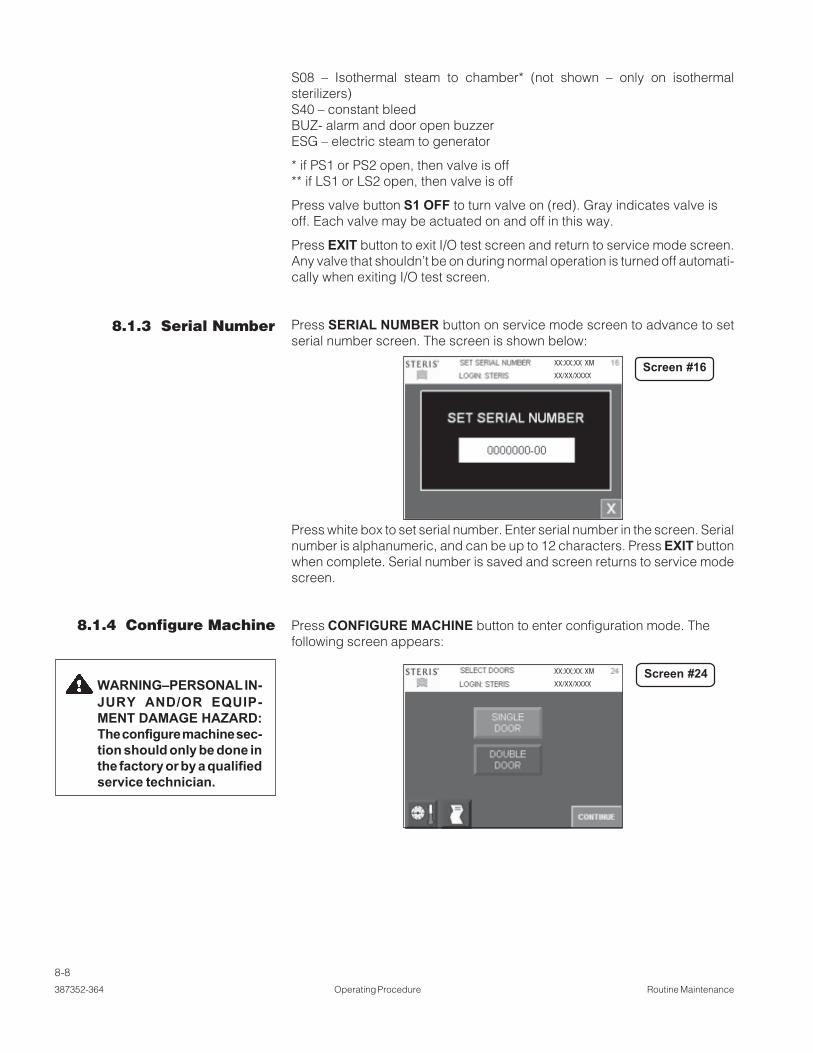
8-8
387352-364 Operating Procedure Routine Maintenance
S08 – Isothermal steam to chamber* (not shown – only on isothermalsterilizers)S40 – constant bleedBUZ- alarm and door open buzzerESG – electric steam to generator
* if PS1 or PS2 open, then valve is off** if LS1 or LS2 open, then valve is off
Press valve button S1 OFF to turn valve on (red). Gray indicates valve isoff. Each valve may be actuated on and off in this way.
Press EXIT button to exit I/O test screen and return to service mode screen.Any valve that shouldn’t be on during normal operation is turned off automati-cally when exiting I/O test screen.
Press SERIAL NUMBER button on service mode screen to advance to setserial number screen. The screen is shown below:
8.1.3 Serial Number
Press white box to set serial number. Enter serial number in the screen. Serialnumber is alphanumeric, and can be up to 12 characters. Press EXIT buttonwhen complete. Serial number is saved and screen returns to service modescreen.
Press CONFIGURE MACHINE button to enter configuration mode. Thefollowing screen appears:
XX:XX:XX XM
XX/XX/XXXX
8.1.4 Configure Machine
XX:XX:XX XM
XX/XX/XXXXWARNING–PERSONAL IN-JURY AND/OR EQUIP-MENT DAMAGE HAZARD:The configure machine sec-tion should only be done inthe factory or by a qualifiedservice technician.
Screen #16
Screen #24

8-9
Routine Maintenance Operating Procedure 387352-364
Select either single door or double door by pressing appropriate button. Redindicates option is selected. Make sure selection is correct based on machinetype. Press CONTINUE button when complete. The following screen appears:
XX:XX:XX XM
XX/XX/XXXX
The display automatically shows correct sterilizer type. If sterilizer type isincorrect (i.e., GRAVITY is shown and it should be a PREVAC sterilizer),contact service. If sterilizer type is changed, values must be defaulted.
Press CONTINUE button when complete. The following screen appears:
XX:XX:XX XM
XX/XX/XXXX
If sterilizer has an electric steam generator, press button to make it red;otherwise, button should stay blue. Press CONTINUE button when complete.The following screen appears:
XX:XX:XX XM
XX/XX/XXXX
Screen #26
Screen #27
Screen #37

8-10
387352-364 Operating Procedure Routine Maintenance
If sterilize has a load probe, press button to make it red, otherwise buttonshould stay blue as shown above. Press CONTINUE button when complete.The following display appears:
There are two different steam sources:
1. Jacket to chamber steam
2. Separate steam
The jacket to chamber steam source indicates steam going to chambercomes from jacket. The separate steam source means steam going tochamber comes directly from a generator or from house steam. The screenabove shows jacket to chamber steam source selected. Press SEPARATESTEAM button to select separate steam source. Once selected steam sourceappears on the display, press CONTINUE button. The screen returns toservice mode display. Press EXIT button to return to main menu.
XX:XX:XX XM
XX/XX/XXXX
XX:XX:XX XM
XX/XX/XXXX
Screen #31
Screen #13

8-11
Routine Maintenance Operating Procedure 387352-364
The printer paper roll should be changed whenever a colored strip is visibleon one or both edges of the printout paper.
PAPER LOADING:1. Open front cover of printer to access paper compartment.
2. Tilt printer mechanism forward to access paper holder. See Figure 8.1 forthe following steps.
3. Remove old paper core.
4. Notice loading diagram on back of printer case. Refer to this when loadingpaper.
5. Insert new paper into paper holder with loose end of paper placed into slotat top of print mechanism. Front panel LED should be flashing.
6. While holding paper in print mechanism, push front panel switch to Feedposition (Up). Paper should feed into print mechanism and out the front.Refer to Figure 8.2.
7. Continue feeding paper until there is about eight inches of paper exitingprint mechanism.
8. Guide paper between paper guide rod #1 and plastic window until it exitsat top paper guide rod #2. Make sure paper goes around this guidecorrectly. Refer to Figure 8.3.
9. Make a slight bend in paper edge and place bent paper edge into slot onthe take-up spindle. Hold paper on to paper spindle.
10. Push the front panel switch to Feed position, paper should then wraparound spindle. If this doesn’t, remove paper and start at step 9 again.
11. Once take-up is loaded, push front panel switch to Reprint (down)position. This procedure starts a print cycle (test print or reprint).
12. Close front cover while print is taking place. This step keeps paper tightaround take-up.
8.2 Change PrinterPaper Roll
(Cybertech Printer)
Figure 8-1. Paper Compartment

8-12
387352-364 Operating Procedure Routine Maintenance
Figure 8-2. Paper Feed Position
Figure 8-3. Paper Guide

8-13
Routine Maintenance Operating Procedure 387352-364
• TAKE-UP LOADING:1. When it is desired to remove stored paper from take-up, open front cover
of printer.
2. While grasping take-up spindle and paper, push take-up release slightly toright until spindle is free. Refer to Figure 8-3 for take-up release position,
3. Simply slide paper off open end of take-up.
4. If paper does not release, rotate paper counter-clockwise, while holdingspindle end bell. Then slide roll of paper off.
5. Replace spindle on to take-up.
8.3 Change PrinterPaper Roll (Mylox
Printer)
To change the printer paper roll for the Mylox style printer, follow the stepsgiven below.
1. Open the top cover of the printer and place the paper roll in position,observing the direction of the arrow indicated in Figure 8-4.
2. Insert the end of the roll into slit of print mechanism (see Figure 8-4); paperauto-loads after a slight delay.
3. In cases where auto-loading feature is not installed on the system, pressFEED key (see Figure 8-4) so that a few centimeters of paper come out ofthe printer.
4. Insert the end into the slit on the top of the printer and close it.
Figure 8-4. Change Paper for Mylox-style Printer
Place Paper Roll asIndicated
FEED Key
Feed Through End ofPaper Roll
Press Here to RemoveSpent Printer Cartridge
Turn Knurled Knob toTighten Printer Ribbon

8-14
387352-364 Operating Procedure Routine Maintenance
8.4 Change PrinterRibbon (Mylox
Printer)
1. Open the top of the printer and remove the old ribbon cartridge by pressingdown at point indicated in Figure 8-4.
2. Insert the new ribbon, making sure that it is correctly positioned.
3. Pull the ribbon tight turning the knurled knob (see Figure 8-4), then closethe printer's top again.

8-15
Routine Maintenance Operating Procedure 387352-364
Important: The chamber drain strainer must be cleaned at least once a day,preferably in the morning before running the first cycle.
1. Remove drain strainer from drain in bottom in chamber.
2. Remove any obvious debris from strainer. If necessary, clear screen instrainer using a brush, wire, or similar tool.
3. Once strainer has been cleared of obvious debris, reverse strainer underrunning water.
4. Replace strainer in chamber drain.
Flush chamber drain as follows whenever line becomes clogged:
See warnings for cleaning chamber drain strainer.
1. Turn OFF steam supply valve. Wait until jacket pressure is zero. Wait untilchamber has cooled to room temperature.
2. Remove chamber drain strainer. Clean strainer using procedures givenabove, if necessary.
3. Pour solution of 60 mL (~1/4 cup) of STERIS sonic detergent or Liqui-Jet 2Instrument Detergent and 500 mL (~1 pint) of hot water into the drain.Solution may puddle in the bottom of the chamber.
… OR…
4. Should these detergents be unavailable, you may use a hot solution of15 mL (~1 tablespoon) of tri-sodium phosphate to 500 mL (~1 pint) of hotwater.
5. Open door and place strainer back in drain.
8.5 Clean ChamberDrain Strainer
8.6 Flush ChamberDrain

9-1
Preventive Maintenance Operating Procedure 387352-364
PREVENTIVE MAINTENANCE 9
9.1 MaintenanceSchedule
Maintenance procedures described in this section must be performed regu-larly at indicated intervals, using maintenance schedule in Table 9-1 as aguide. Local conditions (water quality, usage, etc.) may require more frequentmaintenance than indicated. Refer to maintenance manual (purchasedseparately) for replacement parts lists.
Customer should maintain a record of all maintenance procedures performedon sterilizer.
If a problem occurs, refer to alarm section.
NOTE: Never permit unqualified persons to service the sterilizer.
WARNING-SHOCK ANDBURN HAZARD: Regularlyscheduled preventive main-tenance is required for safeand reliable operation of thisequipment. Contact yourSTERIS Service Representa-tive to schedule preventivemaintenance.
WARNING-PERSONAL IN-JURY OR EQUIPMENT DAM-AGE HAZARD: Repairs andadjustments to this equip-ment must be made only byfully qualified service person-nel. Maintenance performedby inexperienced, unqualifiedpersons or installation of un-authorized parts could causepersonal injury or result incostly equipment damage.
Service required Minimum Frequency
1.0 PREPARATION FOR PREVENTIVE MAINTENANCE
1.1 Discuss equipment with operators and check printouts. 6x per year
1.2 Follow appropriate safety procedures; prepare unit for preventive maintenance. 6x per year
2.0 DOOR ASSEMBLY (EACH DOOR ON A DOUBLE DOOR UNIT)
2.1 Verify proper door and door proximity switch operation.Adjust switch(s), if needed. 6x per year
2.2 Check condition of door gasket for wear and tear. Replace, as needed 6x per year
3.0 VALVES
3.1 Verify each hand valve operates smoothly, check valve packing for leaks,rebuild or replace, as needed.* Steam supply valve. 6x per year* Water supply valve. 6x per year
3.2 Replace check valves. 1x per year
3.3 Rebuild steam supply manifold. 1x per year
3.4 Rebuild all solenoid valves. 1x per year
Table 9-1. Recommended Maintenance Schedule

9-2
387352-364 Operating Procedure Preventive Maintenance
3.0 VALVES (Cont.)
3.5 Rebuild all check valves. 1x per year
3.6 Rebuild steam control valve (PRV). 1x per year
3.7 Verify proper setting/flow rate control valves. Replace, if needed. 2x per year
3.8 Verify that safety valve is not leaking. 6x per year
3.9 Replace safety valve. 1x per year
4.0 MISC. PIPING COMPONENTS
4.1 Inspect steam strainer for debris. Clean, as needed. 2x per year
4.2 Inspect water strainer for debris. Clean, as needed. 2x per year
4.3 Inspect jacket strainer for debris. Clean, as needed. 2x per year
4.4 Inspect chamber drain strainer for debris. Clean, as needed. 6x per year
4.5 Replace air filter cartridge. 1x per year
4.6 Chamber and jacket gauge(s) – verify proper operation. Replace, if needed. 6x per year
4.7 Rebuild chamber and jacket traps. 1x per year
4.8 Verify that there are no leaks. 6x per year
4.9 Verify that door lock piston operates correctly. 6x per year
5.0 CONTROL
5.1 Verify printer and paper take-up operate properly. Check printoutfor darkness, missing dots, etc. 6x per year
5.2 Verify all touch panels function properly (O.E. and N.O.E.). 6x per year
5.3 Verify date and time are correct. If not, correct. 6x per year
5.4 Verify operation of battery backed RAM. Replace, as needed. 6x per year
5.5 Verify buzzer is working. 6x per year
5.6 Verify water level sensor operates properly. 6x per year
5.7 Verify functional operation of each valve using the service mode I/O test. 6x per year
5.8 Verify temperature with pressure displays/printouts. 6x per year
5.9 Verify temperature and pressure settings. 6x per year
6.0 SAFETY TESTING
6.1 Inspect ground bond. 1x per year
6.2 Inspect steam connection to sterilizer. 1x per year
6.3 Inspect water connection to sterilizer. 1x per year
6.4 Inspect drain connection to sterilizer. 1x per year
6.5 Test ground continuity to sterilizer per EN 61010-1. 1x per year
Service required Minimum Frequency
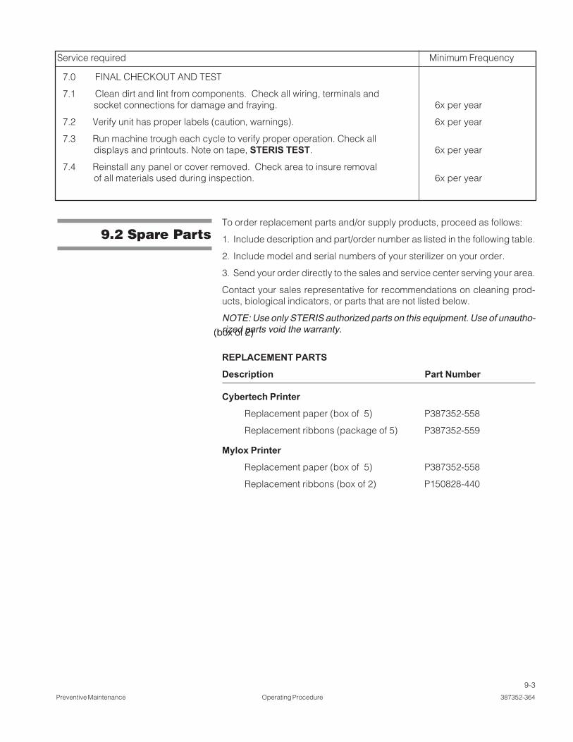
9-3
Preventive Maintenance Operating Procedure 387352-364
Service required Minimum Frequency
7.0 FINAL CHECKOUT AND TEST
7.1 Clean dirt and lint from components. Check all wiring, terminals andsocket connections for damage and fraying. 6x per year
7.2 Verify unit has proper labels (caution, warnings). 6x per year
7.3 Run machine trough each cycle to verify proper operation. Check alldisplays and printouts. Note on tape, STERIS TEST. 6x per year
7.4 Reinstall any panel or cover removed. Check area to insure removalof all materials used during inspection. 6x per year
9.2 Spare PartsTo order replacement parts and/or supply products, proceed as follows:
1. Include description and part/order number as listed in the following table.
2. Include model and serial numbers of your sterilizer on your order.
3. Send your order directly to the sales and service center serving your area.
Contact your sales representative for recommendations on cleaning prod-ucts, biological indicators, or parts that are not listed below.
NOTE: Use only STERIS authorized parts on this equipment. Use of unautho-rized parts void the warranty.
REPLACEMENT PARTS
Description Part Number
Cybertech Printer
Replacement paper (box of 5) P387352-558
Replacement ribbons (package of 5) P387352-559
Mylox Printer
Replacement paper (box of 5) P387352-558
Replacement ribbons (box of 2) P150828-440
(box of 2)(box of 2)

10-1
Appendix A Operating Procedure 387352-364
APPENDIX A 10
10.1 PLCSpecifications
PLC: MicroLogix® 1200 Controller*Catalog number: 1762-L24BWA
Agency Certification: UL 508, C-UL under CSA C222.2 no. 142, Class I, Div.2, Groups A, B, C, D (UL 1604, C-UL under CSA C222.2 no. 213) and CE
Operating temperature: 0ºC to 55ºC (32ºF to 131ºF) ambient.
Storage temperature: -40º C to 85ºC (-40º F to 185ºF) ambient.
Operating humidity: 5% to 95% relative humidity (non-condensing)
Variables stored in flash memory for permanent storage.
Optional Memory module for program backup.
ANALOG MODULE: 4 CHANNEL INPUT MODULECatalog number: 1762-IF4
Resolution: 15 bits (bipolar)
Repeatability: +/-0.1%
RTD MODULE: 4 CHANNEL INPUT MODULECatalog number: 1762-IR4
Resolution: 0.1ºC (0.1ºF)
Repeatability: +/-0.2ºC (+/- 0.4ºF)
Accuracy: +/-0.9ºC (+/- 1.62ºF)
Maximum drift: +/-0.026ºC/ºC (+/- 0.026º F/ºF)
RELAY OUTPUT MODULE: 8 AC OUTPUTSCatalog number: 1762-OW8
DISPLAY: PANELVIEW PLUS® 600Catalog number: 2711P-T6C20D
COMMUNICATION MODE:Catalog number: 2711P-RN22C
* MicroLogix® 1200 Controller is a registered trademark of Rockwell Automation.