operator manual - augenarztbedarf, … manual auto ref-topographer rt-6000 • read this operator...
TRANSCRIPT
OPERATOR MANUALAuto Ref-Topographer
RT-6000
• Read this Operator Manual throughout before using the RT-6000 Auto Ref-Topogra-pher for your correct and safe operation as designed. If you encounter any question orcomments in the course of operation, ask or advise your local representative or dis-tributor.
• Do not use procedures other than those specified in this manual.
• Keep this operator manual in a place you can access easily.
• If you lose this operator manual, contact your local distributer.
• Contact your local distributor if you have any questions or problems.


CAUTION LABEL
i
• Care should be taken not to stain or damagethe Caution Label.
• If the Caution Label is damaged or illegible, re-port or ask your local representative or TomeyCorporation for replacement.

THE STRUCTURE OF THIS OPERATOR MANUAL
The structure of this Operator Manual is as follows:
1. PRIOR TO USE
Precautions and confirmations for the installation and
usage of the instrument.
2. NAMES AND FUNCTIONS OF THE COMPONENTS
Names and functional descriptions of the components.
3. OPERATING PROCEDURE
Vital information needed for installing and using this
instrument.
4. MAINTENANCE
Routine replacement of spare parts, routine maintenance
and inspections.
5. TROUBLESHOOTING
How to remedy problems.
6. SUPPLIES (Available separately)
Available at option.
7. SPECIFICATIONS
Main specifications for this instrument and of the
approved international standards.
SYMBOLS USED IN THIS OPERATOR MANUAL
The symbols used in this manual represent the following meanings:
Precaution that, if unheeded, will result in a hazardous situationwhere there is imminent danger of serious injury or death.
Precaution that, if unheeded, could result in a hazardous situa-tion where there is a possibility of serious injury or death.
Precaution that, if unheeded, may result in a situation wherethere is a possibility of minor or moderate injury or damage toproperty.
Special precaution suggested by the manufacuter that either di-rectly or indirectly relates to the safety of personnel or to the pro-tection of property.
ii
TABLES OF CONTENTS1. PRIOR TO USE ....................................................................................................................... 1
1.1 SAFETY PRECAUTIONS................................................................................................. 1
1.2 UNPACKING ..................................................................................................................... 5
1.3 GLOSSARY ....................................................................................................................... 7
1.4 OUTLINE OF OPERATIONS ......................................................................................... 11
2. NAMES AND FUNCTIONS OF THE COMPONENTS ................................................... 13
2.1 FRONT SIDE ( EXAMINER’S SIDE ) ........................................................................... 13
2.2 BACK SIDE ( PATIENT’S SIDE ) ................................................................................. 15
3. OPERATING PROCEDURES............................................................................................. 17
3.1 SAFETY PRECAUTIONS............................................................................................... 17
3.2 PREPARATIONS FOR OPERATION ............................................................................ 19
3.2.1 CONNECTING OF THE POWER CORD .................................................................... 19
3.2.2 CHECKING OF THE PRINTER PAPER...................................................................... 19
3.2.3 DESENGAGING THE TRAVEL LOCK ...................................................................... 20
3.3 OPERATING PROCEDURES......................................................................................... 21
3.3.1 STARTING .................................................................................................................... 21
3.3.2 SCREEN COMPOSITION............................................................................................. 23
3.3.3 OPERATING PROCEDURES OF THE JOYSTICK .................................................... 26
3.3.4 ALIGNMENT ................................................................................................................ 27
3.3.5 MEASUREMENT .......................................................................................................... 31
3.3.6 SLEEP MODE ................................................................................................................ 32
3.4 SETTING OF OPERATING CONDITIONS .................................................................. 33
3.4.1 SETTING OF THE SCREEN ........................................................................................ 33
3.4.2 SETTING OF REF / KERATOMETER ........................................................................ 35
3.4.3 SETTING OF TOPOGRAPHY...................................................................................... 38
3.4.4 SETTING OF DATE / TIME ......................................................................................... 42
3.4.5 SETTING OF CONTACT LENS LIST ......................................................................... 43
3.4.6 SETTING OF COMMON .............................................................................................. 45
3.4.7 SETTING OF NETWORK COMMUNICATION......................................................... 51
3.4.8 INFORMATION ............................................................................................................ 99
3.5 REFRACTOMETER MODE ......................................................................................... 101
3.5.1 OPERATING SCREEN ............................................................................................... 101
3.5.2 MEASUREMENT ........................................................................................................ 103
3.5.3 IOL AND CATARACT MODE................................................................................... 106
3.5.4 PRINT ........................................................................................................................... 108
3.5.5 MODE CHANGE ......................................................................................................... 111
3.6 KERATOMETER MODE .............................................................................................. 113
3.6.1 OPERATING SCREEN ............................................................................................... 113
3.6.2 MEASUREMENT ........................................................................................................ 115
3.6.3 PRINT ........................................................................................................................... 117
3.6.4 MODE CHANGE ......................................................................................................... 119
iii
3.7 REF / KERATOMETER MODE ................................................................................... 121
3.7.1 OPERATING SCREEN ............................................................................................... 121
3.7.2 MEASUREMENT ........................................................................................................ 123
3.7.3 IOL AND CATARACT MODE................................................................................... 126
3.7.4 PRINT ........................................................................................................................... 128
3.7.5 MODE CHANGE ......................................................................................................... 131
3.8 CONTACT LENS MODE.............................................................................................. 133
3.8.1 OPERATING SCREEN ............................................................................................... 133
3.8.2 MEASUREMENT ........................................................................................................ 134
3.8.3 PRINT ........................................................................................................................... 138
3.8.4 MODE CHANGE ......................................................................................................... 139
3.9 TOPOGRAPHY MODE................................................................................................. 141
3.9.1 OPERATING SCREEN ............................................................................................... 141
3.9.2 MEASUREMENT ........................................................................................................ 143
3.9.3 SINGLE MAP SCREEN .............................................................................................. 148
3.9.4 DUAL MAP SCREEN ................................................................................................. 156
3.9.5 MODE CHNAGE ......................................................................................................... 162
4. MAINTENANCE ................................................................................................................. 165
4.1 WARRANTY ................................................................................................................. 165
4.2 ROUTINE MAINTENANCE ........................................................................................ 166
4.3 REPLACING OF SUPPLIES ......................................................................................... 167
4.3.1 LOADING OF PRINTING PAPER ROLL ................................................................. 167
4.3.2 CHANGING OF THE FUSE ....................................................................................... 169
4.3.3 REPLACING OF THE CHIN REST PAPER .............................................................. 170
4.4 STORING ....................................................................................................................... 171
4.5 DISPOSAL OF PACKAGING MATERIALS............................................................... 172
5. TROUBLESHOOTING ...................................................................................................... 173
5.1 GENERAL TROUBLESHOOTING .............................................................................. 173
5.2 ERROR MESSAGE ....................................................................................................... 175
5.2.1 START UP ................................................................................................................... 175
5.2.2 REFRACTOMETER / KERATOMETER ................................................................... 178
5.2.3 KERATOMETER ........................................................................................................ 180
5.2.4 TOPOGRAPHY ........................................................................................................... 181
5.2.5 PRINTER...................................................................................................................... 184
5.2.6 DATA COMMUNICATION ....................................................................................... 185
6. SUPPLIES (Available separately) ...................................................................................... 187
7. SPECIFICATIONS ............................................................................................................. 189
iv

11.1 SAFETY PRECAUTIONS
1. PRIOR TO USE
• Carefully move the upper unit of this instrumentnot to cause the cone to touch the patient, whichmay otherwise cause to harm the patient.
• Please read this operator manual throughly be-fore operating this instrument.
• Do not use any procedures other than thosespecified in this Manual.
1.1 SAFETY PRECAUTIONS
• Review and observe the following items beforeinstalling this instrument.
* Install the instrument in a moisture free location.
* Do not install this instrument where it may be
subjected to adverse influences, such as sulfur in air,
salts, dusts, direct sunlight, poor ventilation, high
humidity, extreme temperatures, or high atmospheric
pressure.
* Do not install this instrument in a place where
chemicals are stored or where gasses may be
generated.
* Be cautious of stability factors, such as tilting,
vibration, and shock (including adverse events which
may be caused by relocation).
* Be sure to use specified mains frequency, voltage and
allowable current (or power consumption).
* Properly connect the grounding wire.
• Prior to using this Instrument, please observe thefollowing items:
* Make sure again that the grounding wire has been
connected properly.
* Connect the power source cord safely and securely.
* When connecting the communications connector or the
printer connector to the instrument, be sure to have
advice by Tomey's personnel in charge.

2
• Give the following cautions while using this in-strument:
* Care must be given to the clearance between the upper
part and the lower part of the instrument so as not to
pinch or harm your hand.
* Do not apply an excessive force to the cone by
grabbing or pressing which may otherwise interrupt the
operation of the instrument to cause its malfunction or
measurement failure.
* Always watch the instrument and the patient on any
abnormal condition that may be caused.
* If any abnormal condition is found with the instrument
or the patient, suspend your operation in such a manner
as ensuring the safety of the patient patient or take
appropriate countermeasures, such as y stopping the
operation of the instrument.
* Please do not apply the measured results like dioptry,
corneal radii, PD value, residual astigmatism, base
curve of a contact lens, first selection of a contact lens
list for fitting spectacles or contact lenses. If may cause
asthenopia or corneal disorders. Please evaluate the
validity of the results comprehensively.
* Please confirm the correctness of corneal radii with a
topographer or other instruments when one of the
following cases happens. Incorrect corneal radii may
cause re-operation of IOL surgery.
1). The results come with Error Mark (E).
2). There is a big difference in corneal radii between
the right and left eye.
3). The diopter of the selected IOL is less popular or
is out of the range usually used.
1.1 SAFETY PRECAUTIONS

31.1 SAFETY PRECAUTIONS
• Give the following cautions after using instru-ment.
* Be sure to hold the plug when disconnecting the power
source cord from the receptable. Do not apply an
undue force to the cord.
* Clean the inside of the cone with soft cloth once in a
while.
* As for storing of the instrument, see "4.4 Storing" in
this operator manual.
* Before proceeding in the next patient, remove the top
sheet of the Chin Rest Paper. Clean the head pad with
alcohol soaked cloth.
• When the instrument is malfunctioned, discon-tinue its operation and display such failure. Then,ask your distributor for repair.
• The user is not permitted to remodel all or anypart of the instrument whatsoever the reasonmay be.
• When reusing the instrument after being left un-used for longer than one week, make sure thatthe instrument functions normally and safely, inaccordance with "4.2 ROUTINE MAINTENANCE".
• It should be noted that the cone may possibilytouch the patient. The tip of the cone shall be keptclean, in accordance with "4.2 ROUTINE MAINTE-NANCE".

4 1.1 SAFETY PRECAUTIONS
( This page is left intentionally in blank )

5
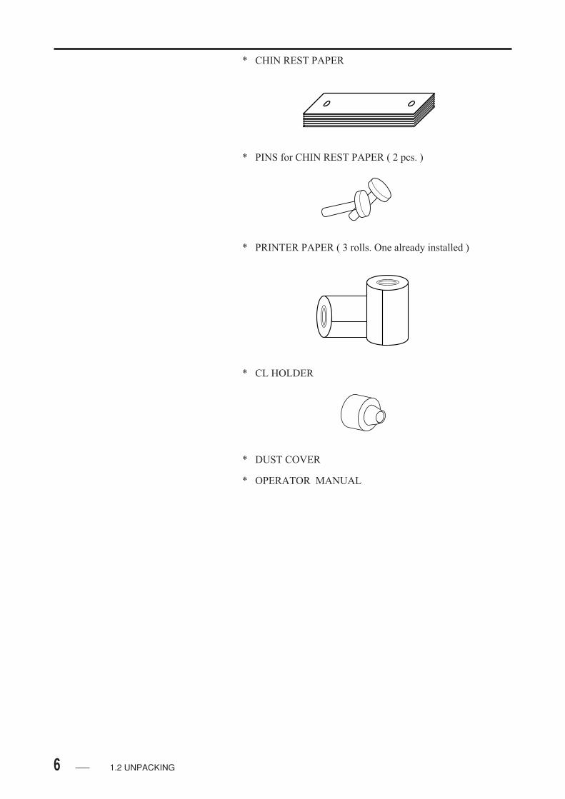
1.2 UNPACKING
After unpacking, make sure that you have received the
following items without damages.
In the event that any item is found missing or damaged,
contact your local distributor.
* AUTO REFTOPOGRAPHER
* MODEL EYE
* POWER CORD
* FUSES: 4 PCS ( 2 OUT OF 4 FUSES ARE ATTACHED
TO THE MAIN UNIT ).
1.2 UNPACKING
6
* CHIN REST PAPER
* PINS for CHIN REST PAPER ( 2 pcs. )
* CL HOLDER
* PRINTER PAPER ( 3 rolls. One already installed )
* DUST COVER
* OPERATOR MANUAL
1.2 UNPACKING

7
1.3 GLOSSARY
Following defines the meaning of the measure terms used
in this Manual.
A............................................. Astigmatism axial angle [ 0 to 180 degrees ]. Repressents the
angle of astigmatism at which the power is located in the
direction crossing the astigmatism axis.
A A ......................................... Auto Alignment ( see " Auto Alignment " ).
A S ......................................... Auto Shot ( see " Auto shot " ).
A V ......................................... Average ( mm ) of strong and weak principal meridians.
B C ......................................... Base Curve ( mm ).
C............................................. Cylinderical Power ( D ).
CAT ....................................... Cataract mode at the time of refractive measurement.
CEI ........................................ Corneal Eccentric Index.
CL .......................................... Contact Lens
D............................................. Diopter / Refractive power for near sight, far sight and
astigmatism.
FL .......................................... Framed Lens or Spectacles / When setting, calculation is made
with a VD or 12 mm or 13.5 mm.
K1 .......................................... Weak Principal Meridian ( mm or D ).
K2 .......................................... Strong Principal Meridians ( mm or D ).
N............................................. Measuring Number of Times ( times ).
PD .......................................... Interpupillary Distance
S ............................................. Spherical Power ( D ) / Represents the power of near sight or
far sight: with ( - ) for near sight and ( + ) for far sight.
TK1 ........................................ Approximate value of weak principal meridian calculated from
topography ( mm or D ).
TK2 ........................................ Approximate value of strong principal meridian calculated from
topography ( mm or D ).
1.3 GLOSSARY
8
VD .......................................... Corneal Apex Distance ( mm ) / Represents the distance between
the corneal apex and the lens to be prescribed. And the
spectacles become 12 mm or 13.5 mm when " VD = CL ",
calculation is made with VD of 0 mm, and the spectacles
become 12 mm or 13.5 mm. when " VD = CL " is displayed,
VD is calculated to be 0 mm.
Absolute Scale ...................... The scale by color distinction method was developed by
Professor Stepham D. K. of Louisiana State University
( LSU ). The scale between 90.0 and 100.0D is divided into 26
by allotting specific colors. This scale shows the identical
refraction power in the identical position for all the eyes
measured, which makes data comparison with other
measurement easy. The central part ( normal range ) of the
scale is divided with an interval of 1.50D having the standard
value ( 43.0D ) for normal eye at the center, which graduations
are colored with a bright green color. The upper and lower part
of the normal range is divided in an interval of 5.0D. The lower
part of the normal range gradually increases the blue color
darker as the upper part of the normal range gradually increases
the color brighter.
Auto Alignment .................... Misalignment of corneal center from the corneal image is
calculated for right / left, upper / lower, and front / rear to move
the measuring system to the amount of shifts. By using this
function, the examiner roughly adjusts the center of the cornea
with the joystick by watching the corneal images, which will
be followed by automatic alignment of the corneal center.
Automatic Fogging ............... Target is automatically moved to the far sighted side to provide
fogging, which eliminates Patient's eye adjustment.
Auto Shot .............................. Automatical measurement is performed while the corneal center
stays in the auto shot zone.
Corneal Curvature ............... Roundness of the cornea ( mm or D ).
Contact Lens List ................. The data of different contact lens models, which are taken by
measurement, are listed. The list is aimed at selection of the
first trial lens, while the prescription of the final contact lens
must be determined by fitting test.
1.3 GLOSSARY
9
and Error .............................. Refractive measurement may not correctly be made in the
following cases.
• In case the refractive power is not stable due to the
interference adjustment ( see " Adjustment " ).
• In case blinking is too frequent.
• In case the pupil s interfered with the eyelid or eyelash.
• In case the optic media of the patient eye is stained with
excessive turbid ( such as cataract and hemorrhage of eye
grand ).
• In case the measuring range of the equipment is exceeded.
Reliability coefficient of data is printed on the right end of
each measured value in a number of 0 to 9. Error
information is printed in two steps, depending on the degree
of error cause.
The mark of " e " is printed on the right side of measued
value, or which data reliability is inferior to that for ordinary
measurement.
Even in case of three consecutive measuring errors, " E "
mark is printed on the right side of measured values for
reference. Therefore, the reliability of data is inferior to that
for ordinary measurement.
Sleep Mode............................ In the Sleep Mode, the screen becomes dark with the power as
left ON, continuously illuminating the Power Lamp only. The
Sleep Mode functions in the Start Screen, the Measurement
Screen, and the Topography Map Display Screen, but does not
for the Setting Screen, which can be released by pressing the
MEASUREMENT BUTTON or changing the right/left with
the Joystick.
Adjustment ........................... Adjustment is made when focusing by swelling the lens to see
or peep a near object or when becoming tense.
Astigmatism Axis ................. The line connecting the points of the highest refractive values
and that connecting the points of the lowest refractive values
on the color map are displayed, which is not displayed if the
astigmatism is less than 1.0D.
Fixation Target ..................... Target guide Patient's fixation.
Reliability Coefficient
1.3 GLOSSARY
Display Instantaneous

10
Normalized Scale .................. Refractive values obtained from analytical results are
automatically distinguished with colors. This scale is graduated
with different colors for examining detailed configuration, of
which colors should cover only the range of refractive value
with which the measuring eye has as the results of analysis.
Sharp slope is displayed in a warm color, while a gentle
displayed in a cold color. Similar onfigurations are always
displayed in similar colors, unless absolute information of
refractive values is requested. In other word, corneas having a
similar configuration are displayed in similar colors in their
topography map. This scale is graduated into 11 parts with an
equal interval, and if the difference between the highest
refractive value and the lowest refractive value is large, while
if that between the two is smaller, the area of one color is less.
The minimum interval shall be 0.40D.
Base Curve ............................ Inner curve of the contact lens ( mm ).
Area Astigmatism ................ Strong meridian in the areas of 3 mm, 5 mm, and 7 mm from
the center of the cornea and refractive values ( mm or D ) and
axial angle on the strong and weak meridians are displayed. In
case the astigmatism is less than 10D, no display of such
information is displayed.
Explanations of Buttons
• Display of Help Screen
• Display of Menu Screen
• Display of Measurement Data
• Change mm and Diopter Display
• Display of Contact Lens Fitting Screen
• Display of Patient Data Input
• Display of Topography Map
1.3 GLOSSARY
Axis Display .......................... Strong and weak principal meridians, which always cross at
right angle. No display is given in case astigmatism is less than
0.20D.
Crossing Astigmatism
?
mm/D

11
1.4 OUTLINE OF OPERATIONS
• Refractive power of an eye is examined by measuring the
infrared light reflected on the retina. Corneal topography and
curvature of the eye are also examined by measuring the
reflected light on the corneal surface.
• The patient places his chin on the Chin Rest and his / her
forhead on the Forehead Rest and next looks into the
fixation target. The Examiner focuses the bright spot for
centering the eye to be measured by observing on the
monitor. Adjust the bright spot up / down and left / right so
that it comes at the center of the screen. Auto-Alignment is
given by rough adjustment, in a similar manner to that
mentioned above and is given to assist the function used for
automatic alignment. After marking alignment, the examiner
presses the MEASUREMENT BUTTON to automatically
start measurement in the Auto Shot Mode. When
measurement start, the measuring light of infrared or visible
light is projected to analyze the refractive power and the
corneal configuration of the eye to be examined. Press the
PRINT BUTTON to print out measured data.
1.4 OUTLINE OF OPERATION
12
( This page is left intentionally in blank )

13
PRINTER
Measured data is printed by Printer.
Open the cover to load or change the
print paper roll.
MONITOR
The eye to be examined is displayed in
the monitor together with alignment and
measured data.
OPERATION BUTTON
The Operation Button enables various
functions.
POWER CORD INLET
The power cord is inserted here.
MEASUREMENT BUTTON
Measurement starts when this button is
pressed.
JOYSTICK
Moves the measurement window right /
left, up / down, and front / back.
TRAVEL LOCK
When moving the instrument, fix the up-
per unit with the fixed screws securely.
FUSES ( 2 PCS )
The Fuse Box is located at the bottom of
the instrument.
POWER SWITCH
Turns the power ON/OFF.
"1" is ON, and "0" is OFF.
2. NAMES AND FUNCTIONS OF THE COMPONENTS
2.1 FRONT SIDE ( EXAMINER'S SIDE )
2.1 FRONT SIDE ( EXAMINER'S SIDE )
14
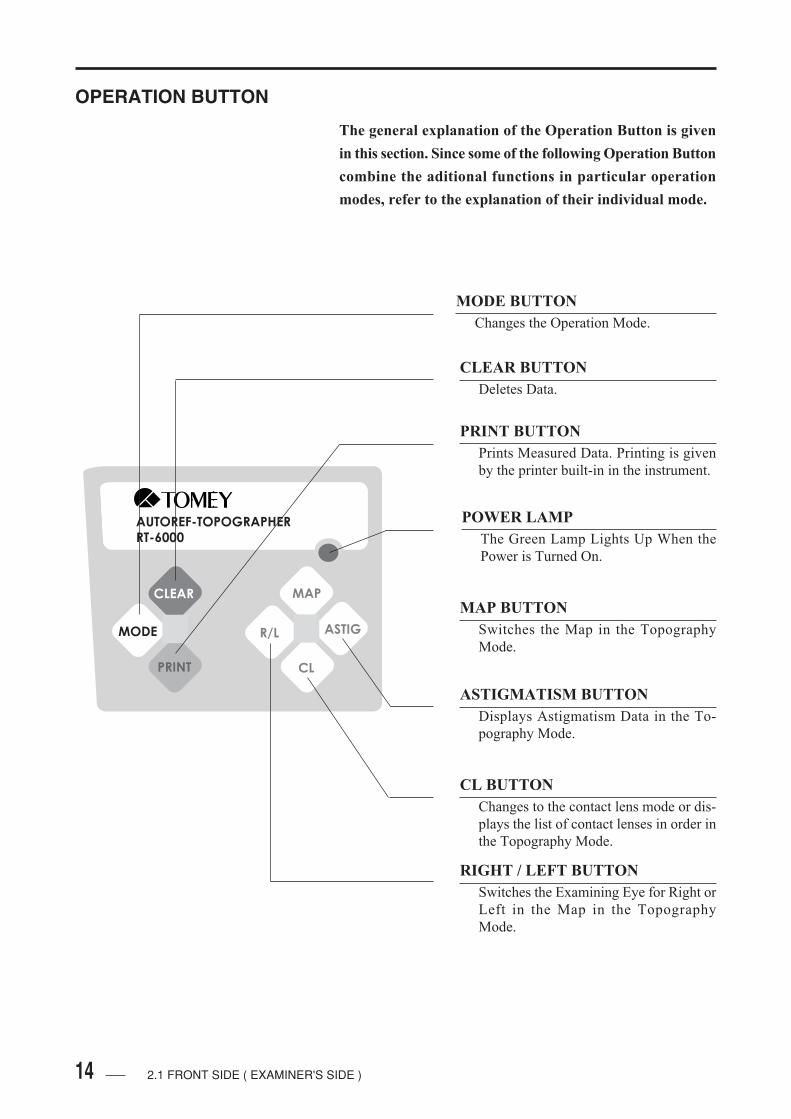
OPERATION BUTTON
The general explanation of the Operation Button is given
in this section. Since some of the following Operation Button
combine the aditional functions in particular operation
modes, refer to the explanation of their individual mode.
PRINT BUTTON
Prints Measured Data. Printing is given
by the printer built-in in the instrument.
CLEAR BUTTON
Deletes Data.
MODE BUTTON
Changes the Operation Mode.
ASTIGMATISM BUTTON
Displays Astigmatism Data in the To-
pography Mode.
CL BUTTON
Changes to the contact lens mode or dis-
plays the list of contact lenses in order in
the Topography Mode.
POWER LAMP
The Green Lamp Lights Up When the
Power is Turned On.
MAP BUTTON
Switches the Map in the Topography
Mode.
RIGHT / LEFT BUTTON
Switches the Examining Eye for Right or
Left in the Map in the Topography
Mode.
AUTOREF-TOPOGRAPHER
RT-6000
CLEAR
MODE
MAP
R/L ASTIG
CL
2.1 FRONT SIDE ( EXAMINER'S SIDE )

15
2.2 BACK SIDE ( PATIENT'S SIDE )
CHIN REST PAPER
Use the new clean Chin Rest Paper for
each patient.
PIN FOR THE CHIN REST PAPER
Secures the Chin Paper with the Pin.
EYE LEVEL MARK
Move the Chin Rest up and down, to align
patient's eye corner to this mark.
CONE
The power cone for reference light pro-
jection when used for measurement in
the Kerato Mode and in the Topography
Mode and can be moved to the front and
back direction.
CHIN REST
Patient's chin is laid on the Chin Rest to
fix the face.
FOREHEAD REST
Fix patient's face by laying patient's
forehead onto this portion.
Z-DIRECTION ALIGNMENT
LIGHT RECEIVING PART
Projecting light is received here to give
its alignment in the Z-direction ( in the
vertical direction to the cornea ).
HEIGHT ADJUSTMENT DIAL
FOR CHIN REST
Adjusts the height of the Chin Rest.
2.2 BACK SIDE ( PATIENT'S SIDE )

16
( This page is left intentionally in blank )

17
3. OPERATING PROCEDURES
3.1 SAFETY PRECAUTIONS
• Do not attempt to lift the Instrument by graspingthe Chinrest section or apply pressure fromabove which may cause the instrument to fallover.
• Do not neither lean yourself against the instru-ment nor apply an undue force to the instrumentfrom its upper part downward.
• Do not also place a liquid contained bottle on theinstrument.
3.1 SAFETY PRECAUTIONS

18
( This page is left intentionally in blank )
19
3.2 PREPARATIONS FOR OPERATION
3.2.1 CONNECTING OF THE POWER CORD
Connect the female socket of the power cord to the plug located
in the under part of the instrument and next connect the male
plug of the power cord on the other side to the receptacle.
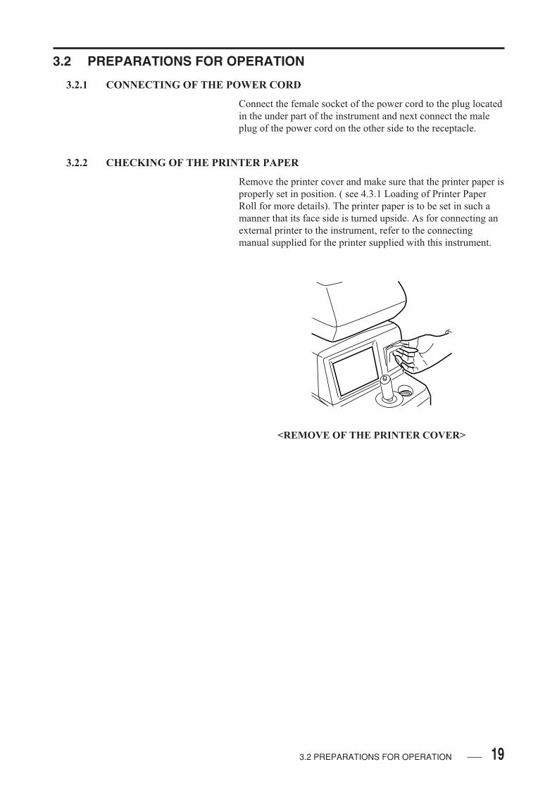
3.2.2 CHECKING OF THE PRINTER PAPER
Remove the printer cover and make sure that the printer paper is
properly set in position. ( see 4.3.1 Loading of Printer Paper
Roll for more details). The printer paper is to be set in such a
manner that its face side is turned upside. As for connecting an
external printer to the instrument, refer to the connecting
manual supplied for the printer supplied with this instrument.
<REMOVE OF THE PRINTER COVER>
3.2 PREPARATIONS FOR OPERATION

20
3.2.3 DESENGAGING THE TRAVEL LOCK
• Disengage the TRAVEL LOCK by turning it
counterclockwise.
• If the JOYSTICK is moved while the TRAVEL LOCK is
still engaged, the instrument cannot move left / right or
forward / backward.
• TRAVEL LOCK should be re-engaged when the instrument
is transported to a new location.
<RELEASING OF THE TRAVEL LOCK>
3.2 PREPARATIONS FOR OPERATION
21
3.3 OPERATING PROCEDURES
• The cone in the Topography Mode is projectedaway from the instrument; therefore, care mustbe taken not to allow it to touch the patient.
• Care must be taken not to place your finger in theopening caused between the upper part and thelower part, which may otherwise harm your fin-ger.
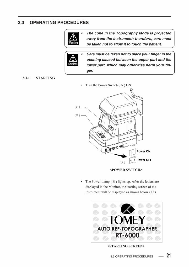
3.3.1 STARTING
• Turn the Power Switch ( A ) ON.
O I
OI Power ON
Power OFF
( B )
( C )
<POWER SWITCH>
• The Power Lamp ( B ) lights up. After the letters are
displayed in the Monitor, the starting screen of the
instrument will be displayed as shown below ( C ).
AUTO REF-TOPOGRAPHER
RT-6000
<STARTING SCREEN>
3.3 OPERATING PROCEDURES
( A )

22
• The starting screen is changed to the Measuring Mode when
pressing the MEASUREMENT BUTTON. The screen is
returned to have the measuring condition which had been set
in the previous mode when the Power Switch was turned
OFF.
• This is example which shows the Measuring Screen in the
Ref / Keratometer Mode to start operate the instrument.
<MEASUREMENT BUTTON>
<REF / KERATOMETER SCREEN>
3.3 OPERATING PROCEDURES
Ref-Keratometer VD=CL
LeftAuto Shot
Auto Alignment
1 / 9 / 02
0:00
1 s C A N PD
K1 K2 AV( ) ( ) N
Clear
K
AA
IOL / CAT
T
AS
?

23
3.3.2 SCREEN COMPOSITION
• The screen composition will be explained with Ref /
Keratometer as example.
• MEASURING NUMBER
The measuring number is displayed in the left upper part of
the screen.
• MEASURING DATA
After measurement is finished, measured data will be
displayed at the upper part of the screen. Data structure
varies on the type of mode, by which no data will displayed
in the topography measurement result.
• MODE DISPLAY
The ongoing mode is displayed at the upper left and in the
lower center of the screen.
<REF / KERATOMETER SCREEN>
3.3 OPERATING PROCEDURES
Ref-Keratometer VD=CL
LeftAuto Shot
Auto Alignment
1 / 9 / 02
0:00
1 s C A N PD
K1 K2 AV( ) ( ) N
Clear
K
AA
IOL / CAT
T
AS
?
MEASURING DATA MEASURING DATA
BUTTON INFORMATION MEASURING CONDITION

24
Ref-Keratometer
1 s C
K1 K2( )
<MODE DISPLAY 1>
<MODE DISPLAY 2>
• BUTTON INFORMATION
The buttons incorporate a multiple number of functions. The
information of the button while being used on displayed at
the lower left part of the screen, which differ from the letters
shown on the buttons.
• The green colored symbol shown in the upperpart of the button indicates that the button hasthe long pressing function of more than two sec-onds. As for each symbol ( see 1.3 GLOSSARY ).
• CONE POSITION
The Cone Position is displayed at the lower center part of the
screen. The Cone Position varies on the type of mode. Three
cone positions colored red, yellow, and green from the
corneal surface are used.
<BUTTON INFORMATION>
Left
<CONE POSITION>
3.3 OPERATING PROCEDURES
AA
IOL / CAT
T
AS
Clear
K
AA
IOL / CAT
T
AS
?

25
• Minute care must be taken when the Cone locatedon the red position, where the Cone is pro-jected most, not to cause the patient to beharmed.
• EYE TO BE MEASURED
The screen indicates which side of the two eyes is being
measured in its lower center. This display is changed by
moving the upper part of the main unit of the instrument.
• MEASURING CONDITION
The condition of Auto Shot and Auto Alignment is displayed
at the lower right part of the screen ( see 1.3 GLOSSARY ).
The condition of " ON " is displayed in green and that of "
OFF " in gray, of which display differs on the type of mode.
• CLOCK
Date and time are displayed in the lower right part of the
screen.
Left
<MEASURING EYE>
tAuto Shot
Auto Alignment
<MEASURING CONDITION>
9/ 1/01
0:00
<CLOCK>
3.3 OPERATING PROCEDURES
26
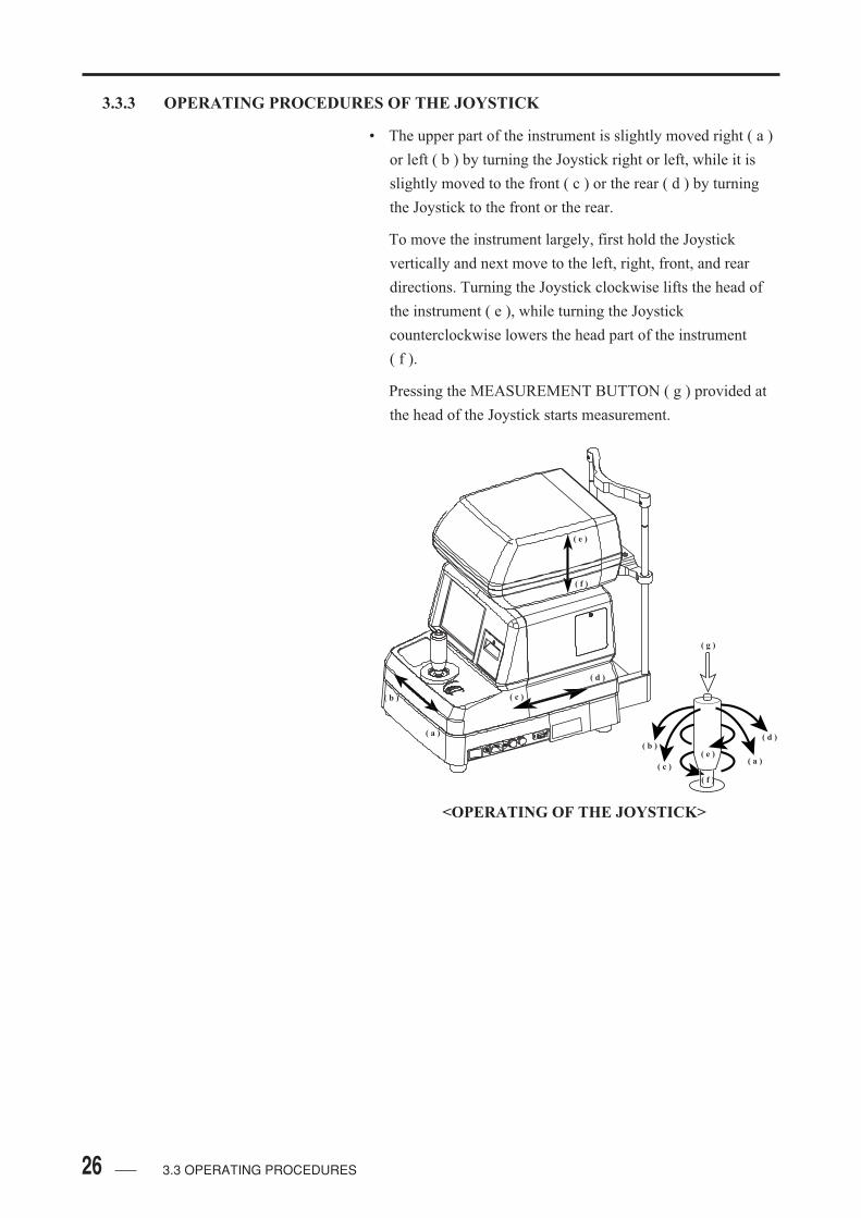
3.3.3 OPERATING PROCEDURES OF THE JOYSTICK
• The upper part of the instrument is slightly moved right ( a )
or left ( b ) by turning the Joystick right or left, while it is
slightly moved to the front ( c ) or the rear ( d ) by turning
the Joystick to the front or the rear.
To move the instrument largely, first hold the Joystick
vertically and next move to the left, right, front, and rear
directions. Turning the Joystick clockwise lifts the head of
the instrument ( e ), while turning the Joystick
counterclockwise lowers the head part of the instrument
( f ).
Pressing the MEASUREMENT BUTTON ( g ) provided at
the head of the Joystick starts measurement.
( a )
( b ) ( c )
( d )
( e )
( f )
( g )
( a )
( d )
( c )
( b )
( f )
( e )
<OPERATING OF THE JOYSTICK>
3.3 OPERATING PROCEDURES

27
3.3.4 ALIGNMENT
• Remove one sheet of the Chin Rest Paper and cleanly wipe
the Forehead Rest clearly with alcohol.
• The patient places his chin on the Chin Rest and his forehead
on the Forehead Rest.
• Turn the Up / Down dial to align the corner of the patient's
eye to the Eye Level Mark.
• Have the patient roughlt look at the fixation target from the
measuring window. The fixation target looks bluring in
process of measurement by Auto Fogging System. Advice
the patient not to feel too tense.
<POSITION OF THE PATIENT>
3.3 OPERATING PROCEDURES
<FIXATION TARGET>

28
• If the focusing position is largely apart from the corneal
surface, the Auto Alignment Zone ( a ) will only display
• Move the reflected light into the auto alignment zone by
operating the Joystick. When the refracted light enters the
auto alignment zero, the vertical line ( b ) showing the
misalignment in the right / left direction ( X-aixs ), the
horizontal line ( c ) showing the misalignment in the up /
down direction ( Y-axis ), and the bar ( d ) showing the
misalignment in the font / rear direction ( Z-axis ) are
displayed in the screen.
• The bar ( d ) showing the misalignment in the front / rear
direction ( Z-axis ) is displayed in the lower part if the head
is in front of the focusing point and in the upper part if the
head is on the side of cornea, of which size varies on the
distance of the bar.
<ALIGNMENT START>
<RECOGNITION OF REFECTED LIGHT>
3.3 OPERATING PROCEDURES
Ref-Keratometer VD=CL
LeftAuto Shot
Auto Alignment
1 / 9 / 02
0:00
1 s C A N PD
Clear
K
AA
IOL / CAT
T
AS
?
K1 K2 AV( ) ( ) N
( b )
( c )
( d )
Refracted Light
Ref-Keratometer VD=CL
LeftAuto Shot
Auto Alignment
1 / 9 / 02
0:00
1 s C A N PD
K1 K2 AV( ) ( ) N
Clear
K
AA
IOL / CAT
T
AS
?
( a )
29
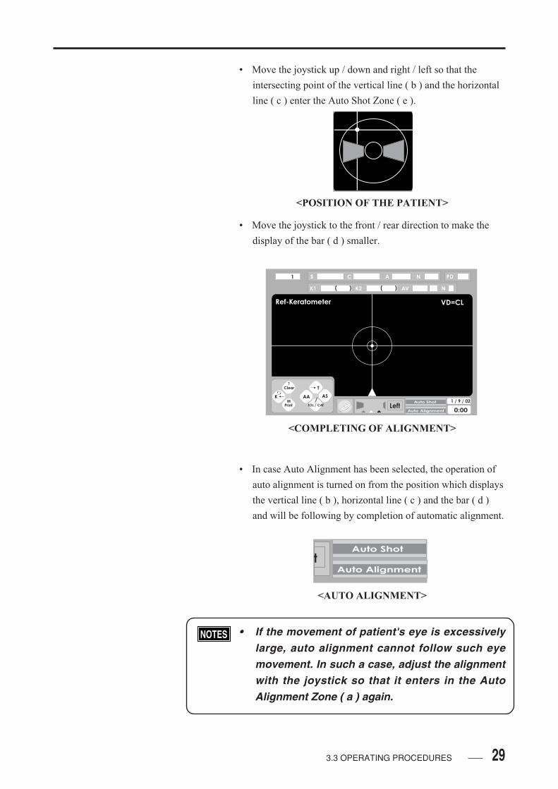
• Move the joystick up / down and right / left so that the
intersecting point of the vertical line ( b ) and the horizontal
line ( c ) enter the Auto Shot Zone ( e ).
• Move the joystick to the front / rear direction to make the
display of the bar ( d ) smaller.
• In case Auto Alignment has been selected, the operation of
auto alignment is turned on from the position which displays
the vertical line ( b ), horizontal line ( c ) and the bar ( d )
and will be following by completion of automatic alignment.
<POSITION OF THE PATIENT>
<COMPLETING OF ALIGNMENT>
tAuto Shot
Auto Alignment
<AUTO ALIGNMENT>
• If the movement of patient's eye is excessivelylarge, auto alignment cannot follow such eyemovement. In such a case, adjust the alignmentwith the joystick so that it enters in the AutoAlignment Zone ( a ) again.
3.3 OPERATING PROCEDURES
Ref-Keratometer VD=CL
LeftAuto Shot
Auto Alignment
1 / 9 / 02
0:00
1 s C A N PD
K1 K2 AV( ) ( ) N
Clear
K
AA
IOL / CAT
T
AS
?

30 3.3 OPERATING PROCEDURES
Press the R / L button to turn the Auto Alignment Mode off.
Press the same button to turn this Mode on again.
If the ASTIG BUTTON is pressed when both Auto
Alignment and Auto Shot are off, Auto Alignment as well as
Auto Shot will automatically be turned on ( see 3.3.5
MEASUREMENT ).
AUTOREF-TOPOGRAPHERRT-6000
CLEAR
MODE
MAP
R/L ASTIG
CL
<DISPLAY OF BUTTONS IN THE SCREEN>
Clear
K
AA
IOL / CAT
T
AS
?
31
3.3.5 MEASUREMENT
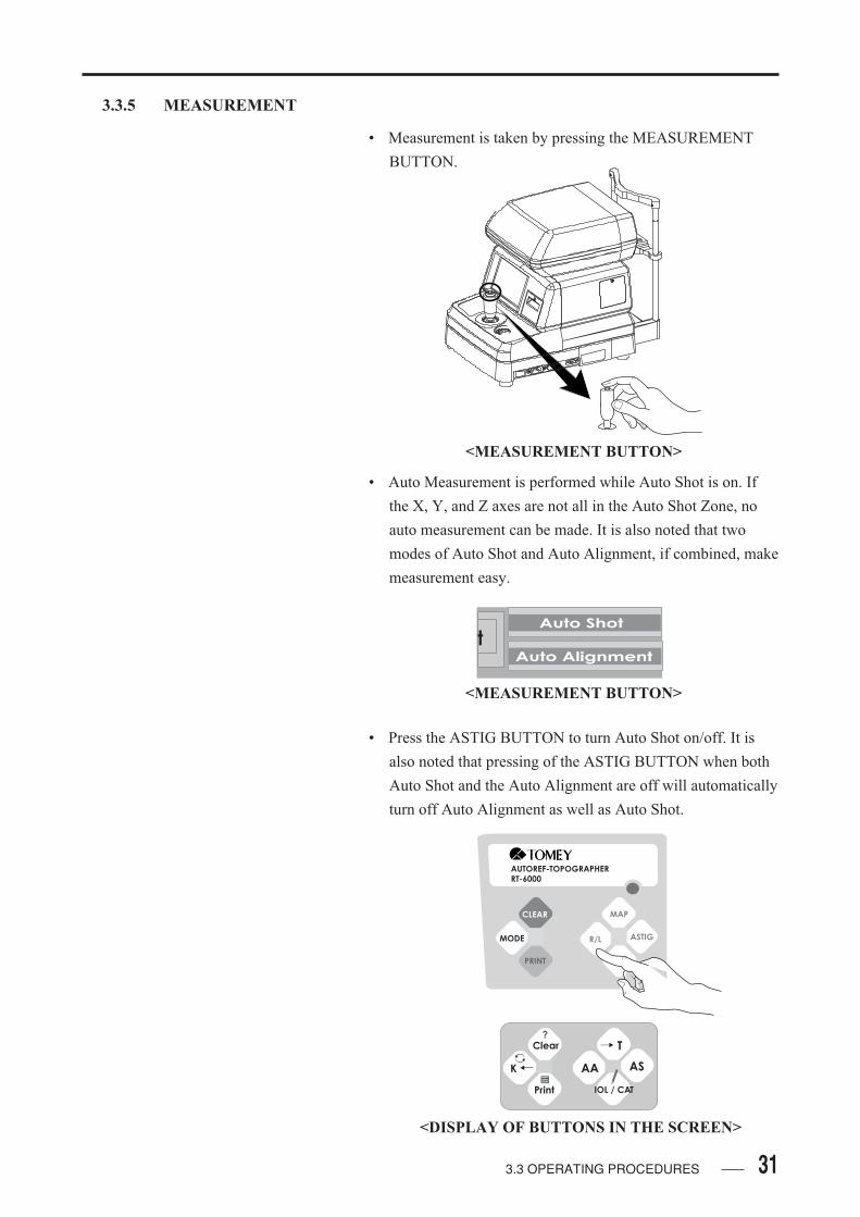
• Measurement is taken by pressing the MEASUREMENT
BUTTON.
• Auto Measurement is performed while Auto Shot is on. If
the X, Y, and Z axes are not all in the Auto Shot Zone, no
auto measurement can be made. It is also noted that two
modes of Auto Shot and Auto Alignment, if combined, make
measurement easy.
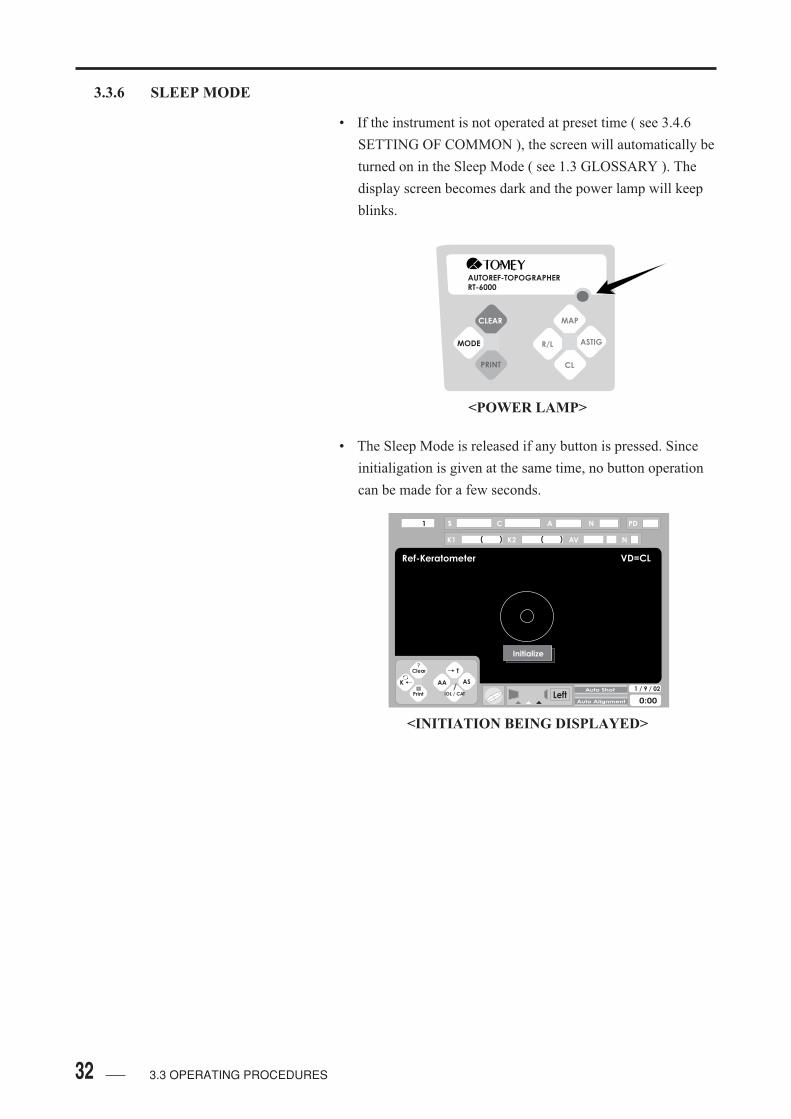
• Press the ASTIG BUTTON to turn Auto Shot on/off. It is
also noted that pressing of the ASTIG BUTTON when both
Auto Shot and the Auto Alignment are off will automatically
turn off Auto Alignment as well as Auto Shot.
<MEASUREMENT BUTTON>
tAuto Shot
Auto Alignment
<MEASUREMENT BUTTON>
AUTOREF-TOPOGRAPHERRT-6000
CLEAR
MODE
MAP
R/L ASTIG
CL
3.3 OPERATING PROCEDURES
<DISPLAY OF BUTTONS IN THE SCREEN>
Clear
K
AA
IOL / CAT
T
AS
?
32 3.3 OPERATING PROCEDURES
3.3.6 SLEEP MODE
• If the instrument is not operated at preset time ( see 3.4.6
SETTING OF COMMON ), the screen will automatically be
turned on in the Sleep Mode ( see 1.3 GLOSSARY ). The
display screen becomes dark and the power lamp will keep
blinks.
• The Sleep Mode is released if any button is pressed. Since
initialigation is given at the same time, no button operation
can be made for a few seconds.
AUTOREF-TOPOGRAPHERRT-6000
CLEAR
MODE
MAP
R/L ASTIG
CL
<POWER LAMP>
<INITIATION BEING DISPLAYED>
Ref-Keratometer VD=CL
LeftAuto Shot
Auto Alignment
1 / 9 / 02
0:00
1 s C A N PD
Initialize
K1 K2 AV( ) ( ) N
Clear
K
AA
IOL / CAT
T
AS
?

33
3.4 SETTING OF OPERATING CONDITIONS
3.4.1 SETTING OF THE SCREEN
• Press the MODE BUTTON for a few seconds, till the
MODE CHANGE SCREEN appears.
AUTOREF-TOPOGRAPHER
RT-6000
CLEAR
MODE
MAP
R/L ASTIG
CL
<DISPLAY OF BUTTON IN THE SCREEN>
<MODE CHANGE SCREEN>
3.4 SETTING OF OPERATING CONDITIONS
Clear
K
AA
IOL / CAT
T
AS
?

34
• Press ASTIG BUTTON to enter Setup Screen.
• On the Setup screen, select and set necessary item for each
mode before going into measurement. If the MAP BUTTON
is pressed, the cursor for item to be set will move upward,
while, if the CL BUTTON is pressed, the cursor for item to
be set will move downward. To select the item to be set,
press the MODE BUTTON.
AUTOREF-TOPOGRAPHERRT-6000
CLEAR
MODE
MAP
R/L ASTIG
CL
<SETUP SCREEN>
AUTOREF-TOPOGRAPHERRT-6000
CLEAR
MODE
MAP
R/L ASTIG
CL
UP
DOWN
3.4 SETTING OF OPERATING CONDITIONS
RT-6000 Setup 0:00
Ref / Keratometer
Topography
Data / Time
Contact Lens List
Common
Information
Exit
CURSOR

35
3.4.2 SETTING OF REF / KERATOMETER
• Select " REF / Keratometer " to enter Ref / Keratometer
Setup Screen.
• When pressing the MAP BUTTON moves the cursor used
for setting the items upward and pressing the CL BUTTON
moves the cursor downward. Pressing the CLEAR
BUTTON displays the screen for Help. Press the MODE
BUTTON to select items to be set.
• VERTEX DISTANCE: For setting of " Corneal Apex
Distance " ( VD ) , select FRAMED LENS or CONTACT
LENS.
Framed Lens:
Setting for spectacle treatment or for general examination is
used. No display is given in the screen for these setting.
Contact Lens:
Setting for contact lens application is used. The refractive
power is calculated when this setting is used. " VD=CL " is
displayed at the right upper part of the screen and printed in
the printing paper.
<REF / KERATOMETER SETTING SCREEN>
AUTOREF-TOPOGRAPHERRT-6000
CLEAR
MODE
MAP
R/L ASTIG
CL
UP
DOWN
CURSOR
3.4 SETTING OF OPERATING CONDITIONS
RT-6000 Setup 0:00
Ref/Keratometer
Vertex Distance
VD in FL Mode
Step
Cylindrical Power
Measurement
RS-232C
Exit
Contact Lens
12mm
0.25D
-
High Speed
NO
[FL/CL]
[12mm/13.5mm]
[0.12D/0.25D]
[ +/+ - / - ]
[Normal/High]
?
Data Communication Disabled
Measurement Number[R:3/5 K:1/3] R: 3 / K:3
[No /9600-38400 / REFTESTER]

36
• VERTEX DISTANCE: VD value ( FL Mode ) is
selected from the VD values fro framed lens, " 12mm " and
" 13.5mm " .
• STEP: As for " Measuring Unit " , the display step for
refractive power is set at " 0.12D " or " 0.25D " .
• CYLINDRICAL POWER:For " Astigmatism Power Read
Changing " , select " + " , " - " , and " +/- " .
" - " [ + ]:
The astigmatism power is always displayed with " + ",
whatever its spherical power may be.
" - " [ - ]:
The astigmatism power is always displayed with " - ",
whatever its spherical power may be.
" - " [ + / - ]:
The symbol of astigmatism power changes by that of
spherical power.
• MEASUREMENT: For " Measurement Mode ", select
" Normal Mode " or " High Speed Mode ".
Normal Mode:
Automatic fogging and measurement continue while the
MEASUREMENT BUTTON is being pressed. Minimize the
interruption bu adjusting the eye to be measured, for higher
measuring accuracy.
High Speed Mode:
Automatic fogging is given in the begining of measurement,
which shall be followed by successive measurement. this
measurement is effectively used for the patient of which eye
fixation is not stable.
3.4 SETTING OF OPERATING CONDITIONS

37
• MEASUREMENT NUMBER: " MEASURING TIMES "
sets the number of measuring times for Refractometer and
Keratometer. Repeated pressing of the MODE BUTTON
permits consecutive settings in the following order.
- R: 3/K: 1 3 times measurement for Refractometer and
1 time measurement for Keratometer.
- R: 3/K: 3 3 times measurement for Refractometer and
3 times measurement for Keratometer.
- R: 5/K: 1 5 times measurement for Refractometer and
1 times measurement for Keratometer.
- R: 5/K: 3 5 times measurement for Refractometer and
3 times measurement for Keratometer.
Single Mode for Refractometer or Keratometer is changed as
per the number of this setting times above.
• DATA COMMUNICATION: There is several different
ways to do data communication from RT-6000.
- NO Not available to do data communication.
- REFTESTER Available to do data communicate Reftester.
- COM (FORMAT1) / COM (FORMAT 2) Available to
do data communicate by RS232C port.
- LAN (FORMAT1) / LAN (FORMAT2)Available to do
data communicaion by LAN port.
- LAN (TOMEY LINK) Currently, not available to use
this function.
• When moving the cursor to " CLOSE " and pressing the
MODE BUTTON, the REF / KERATOMETER setting
screen is closed to return to the Setting Screen.
3.4 SETTING OF OPERATING CONDITIONS
38
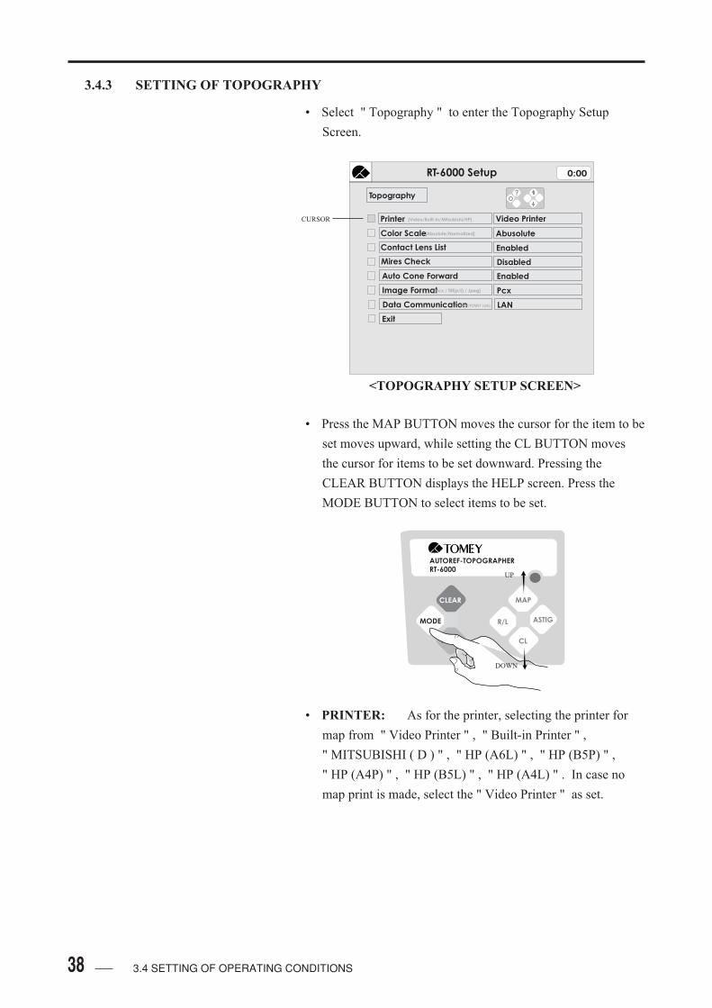
3.4.3 SETTING OF TOPOGRAPHY
• Select " Topography " to enter the Topography Setup
Screen.
• Press the MAP BUTTON moves the cursor for the item to be
set moves upward, while setting the CL BUTTON moves
the cursor for items to be set downward. Pressing the
CLEAR BUTTON displays the HELP screen. Press the
MODE BUTTON to select items to be set.
• PRINTER: As for the printer, selecting the printer for
map from " Video Printer " , " Built-in Printer " ,
" MITSUBISHI ( D ) " , " HP (A6L) " , " HP (B5P) " ,
" HP (A4P) " , " HP (B5L) " , " HP (A4L) " . In case no
map print is made, select the " Video Printer " as set.
<TOPOGRAPHY SETUP SCREEN>
AUTOREF-TOPOGRAPHERRT-6000
CLEAR
MODE
MAP
R/L ASTIG
CL
UP
DOWN
3.4 SETTING OF OPERATING CONDITIONS
CURSOR
RT-6000 Setup 0:00
Topography
Exit
Video Printer
Abusolute
Disabled
Enabled
Printer [Video/Built-in/Mitsubishi/HP]
Color Scale
Contact Lens List
Mires Check
Auto Cone Forward
[Absolute/Normalized]
?
Enabled
Image Format[Pcx / Tiff(p/f) / Jpeg] Pcx
Data Communication[LAN/TOMEY Link] LAN

39
VIDEO PRINTER:
Video Printer implies the Printer which is connected with the
analog RGB connector of the instrument. The color maps for
right and left eyes are respectively printed in separate sheets
or both printed in one sheet. As for the connecting procedure
of the cable of this printer to the instrument, see the
Connecting Manual attached to the printer.
MITSUBISHI ( D ):
This printer mode is selected if the MITSUBISHI DIGITAL
COLOR PRINTER is connected to the instrument. The color
maps for right and left eyes are respectively printed in
separate sheets or both printed in one sheet. As for the
connecting procedure of the cable of this printer to the
instrument, see the Connecting Manual attached to the
printer.
HEWLETT PACKARD ( D ):
Select " HP (A6L) " , " HP (B5P) " , " HP (A4P) " ,
" HP (B5L) " , " HP (A4L) " to use Huwlett Packard made
ink jet printer (serial port model). As for the connexting
procedure of the cable of Hewlett Packard printers to the
instrument, see the Connecting Manual attached to the
printer.
• COLOR SCALE: As for " Color Scale ", set the scale
of the first map after analysis is made at " ABSOLUTE " or
" NORMALIZED " ( See 1.3 GLOSSARY ).
• CONTACT LENS LIST: For " Contact Lens List ",
select " ENABLED " or " DISABLED ".
Enabled:
After the color map is drawn, the list of contact lens
prescription values is displayed.
Disabled:
After the color map is drawn, the list of prescription values
for contact lens is not displayed, but displayed when press
the CL BUTTON.
3.4 SETTING OF OPERATING CONDITIONS

40
• MIRES RING: For " Ring Confirmation ", select
" ENABLED " or " DISABLED ".
Enabled
After recognizing the projected rings, it is necessary to
confirm that the rings are drawn properly. If the rings are
proper, they will, further, be analyed. If, however, not
proper, measurement must be given again.
Disabled:
After the projected rings are identified immediate analysis
will be given. If the image in the map is not proper, the
check screen will be displayed regardless of set condition.
• AUTO CONE FORWARD: For " Auto Cone
Movement ", select " ENABLED " or " DISABLED ".
The cone for ring beam projection is automatically retreated
inside the instrument after measurement is completed. If
measurement is given after drawing the map or if the mode
is changed to topography from a mode other than
topography, the cone must be moved out to the side of
patient from the inner part of the instrument unit.
Enabled:
If the Forehead Rest is fully pulled to the side of patient, the
cone will automatically be moved to such a position that the
Forehead Rest is projected farthest.
Disabled:
The cone cannot be auomatically moved, but can be moved
by Button operation with the Forehead Rest as being fully
pulled toward the patient ( See 3.9 Topography Mode ).
• IMAGE FORMAT: " Imaging Format " is displayed only
when " Network Communication " is at " Yes . " Imaging
Format " is selected from " PCX ", " TIFF(p) ", " TIFF(f) ",
and "JPEG ". Selected image format is outputted in the
computer connected to the network.
3.4 SETTING OF OPERATING CONDITIONS
41
• DATA COMMUNICATION: There is several different
ways to do data communication from RT-6000.
- NO
Not available to do data communication.
- REFTESTER
Available to do data communicate Reftester.
- COM (FORMAT1) / COM (FORMAT 2)
Available to do data communicate by RS232C port.
- LAN (FORMAT1) / LAN (FORMAT2)
Available to do data communicaion by LAN port.
- LAN (TOMEY LINK)
Currently, not available to use this function.
• Move the cursor to " Exit " and press the MODE
BUTTON, to finish and return the Screen to the Topography
Setting Screen.
3.4 SETTING OF OPERATING CONDITIONS
42
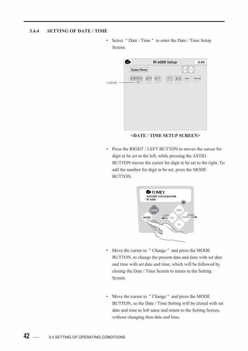
3.4.4 SETTING OF DATE / TIME
• Select " Date / Time " to enter the Date / Time Setup
Screen.
• Press the RIGHT / LEFT BUTTON to moves the cursor for
digit to be set to the left, while pressing the ASTIG
BUTTON moves the cursor for digit to be set to the right. To
add the number for digit to be set, press the MODE
BUTTON.
• Move the cursor to " Change " and press the MODE
BUTTON, to change the present data and time with set date
and time with set date and time, which will be followed by
closing the Date / Time Screen to return to the Setting
Screen.
• Move the cursor to " Change " and press the MODE
BUTTON, so the Date / Time Setting will be closed with set
date and time as left same and return to the Setting Screen,
without changing then date and time.
RT-6000 Setup 0:00
Date/Time
2 0 0 2 90 0 1 1 3 51 Save Cancel
<DATE / TIME SETUP SCREEN>
CURSOR
AUTOREF-TOPOGRAPHERRT-6000
CLEAR
MODE
MAP
R/L ASTIG
CL
LEFT RIGHT
3.4 SETTING OF OPERATING CONDITIONS

43
3.4.5 SETTING OF CONTACT LENS LIST
• Select " Contact Lens List " to enter contact Lens List Setup
Screen.
• The contact lenses with different brands of which display in
the screen and printing are recognised effective are
highlighted with white color in the background, while that
which is not recognised effective is highlighted with gray
color. The contact lens in the cursor position of which brand
is recognised effective has the yellow background. In the
REF / KERATOMETER MODE, KERATOMETER
MODE, and TOPOGRAPHY MODE, the contact lenses
with different brands which are recognised effective in the
list are displayed and printed in such an order as placed in
the list.
• The order of display and / or printing of the contact lenses
with different brands can be changed by the following
procedure. If the CLEAR BUTTON is pressed, the brand in
the cursor position is replaced with that placed one row
above. If the PRINT BUTTON is pressed the brand in the
cursor position is replaced with that placed one row below.
Press the MAP BUTTON to move the cursor down.
<CONTACT LENS LIST SETUP SCREEN>
AUTOREF-TOPOGRAPHERRT-6000
CLEAR
MODE
MAP
R/L ASTIG
CL
UP
DOWN
3.4 SETTING OF OPERATING CONDITIONS
RT-6000 Setup 0:00
Contact Lens List Move Name Move Cursor
contact lens name diam. type
MENICON Z - Rigid
Rigid
Rigid
Rigid
Rigid
Rigid
Soft
Rigid
Rigid
Rigid
Rigid
Rigid
Rigid
Rigid
Rigid
contact lens name diam. type
MENICON EX
MENICON EX
BAUSCH & LOMB Conflex-Air
BAUSCH & LOMB A 90
BAUSCH & LOMB Weflex 55
BAUSCH & LOMB G-72D
BAUSCH & LOMB Quantum I
BAUSCH & LOMB Quantum I
CIBA Fluorocon PE
CIBA Fluorocon PE
CIBA Aquila
CIBA Aquila
CIBA Persecon 92E
CIBA Persecon 92E
CIBA Persecon E
CIBA Persecon E
CIBA Persecon CE
CIBA Persecon CE
HECHT Ascon Standard
9.2
9.6
9.3
9.8
10.3
8.9
9.4
9.9
13.7
14.4
9.0
9.6
9.0
9.6
9.4
9.6
9.8
9.3
9.8
9.3
9.8
9.3
9.8
9.3
9.8
9.2
Save
Cancel
9.9 Rigid
BAUSCH & LOMB Weflex 55
HECHT Ascon Standard
HECHT Ascon Standard
9.6
10.0
Rigid
BAUSCH & LOMB Conflex-Air
BAUSCH & LOMB Conflex-Air
BAUSCH & LOMB Conflex
BAUSCH & LOMB Conflex
BAUSCH & LOMB Conflex
Rigid
Rigid
BAUSCH & LOMB A 90
9.4 Rigid
14.3
Soft
Soft
Rigid
Rigid
BAUSCH & LOMB Quantum II
BAUSCH & LOMB Quantum II
CIBA Fluorocon PE
Rigid
Rigid
Rigid
Rigid
Rigid
Rigid
Rigid
Rigid

44 3.4 SETTING OF OPERATING CONDITIONS
• Move the cursor to " save " and pressing the MODE
BUTTON, the setting of the contact lens brands in the list
are changed and the screen is next closed to return to the
Setting Screen.
• Move the cursor to " Cancel " and pressing the MODE
BUTON, the change of the setting of the brands in the list is
cancelled and the screen is next closed with the list as
keeping its order to return to its Setting Screen.
45
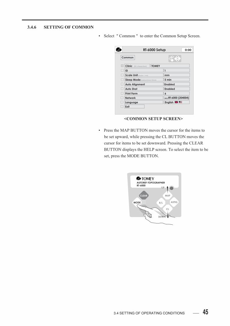
3.4.6 SETTING OF COMMON
• Select " Common " to enter the Common Setup Screen.
• Press the MAP BUTTON moves the cursor for the items to
be set upward, while pressing the CL BUTTON moves the
cursor for items to be set downward. Pressing the CLEAR
BUTTON displays the HELP screen. To select the item to be
set, press the MODE BUTTON.
<COMMON SETUP SCREEN>
AUTOREF-TOPOGRAPHERRT-6000
CLEAR
MODE
MAP
R/L ASTIG
CL
UP
DOWN
3.4 SETTING OF OPERATING CONDITIONS
RT-6000 Setup 0:00
Common
Clinic
Exit
TOMEY[32 characters]
ID
Scale Unit
Sleep Mode[Disabled/5mm/10mm]
1
mm
5 min
Auto Alignment
Auto Shot
Print Form
Enabled
Enabled
Network
6
RT-6000 (204004)
[diopter / mm]
WGC
Language English
?

46 3.4 SETTING OF OPERATING CONDITIONS
• CLINIC: Enter the clinic name to customize the
header of the print out.
• The letters to be selected are moved upward by MAP
BUTTON, to the right by ASTIG BUTTON, to the lower by
CL VUTTON and to the left by R/L BUTTON. The letters
are selected by pressing the MODE BUTTON.
Cancel:
The new name of the clinic which has been inputted is
canceled, followed by closimg the Clinic Name Setting
Screen.
Save:
The name of the clinic is changed with a new name,
following by closing the Clinic Name Setting Screen.
<CLINIC NAME SETTING SCREEN>
AUTOREF-TOPOGRAPHERRT-6000
CLEAR
MODE
MAP
R/L ASTIG
CL
RT-6000 Setup 0:00
Common
Clinic
Exit
TOMEY[32 characters]
ID
Scale Unit
Sleep Mode[Disabled/5mm/10mm]
1
mm
5 min
Auto Alignment
Auto Shot
Print Form
Enabled
Enabled
Network
6
RT-6000 (204004)
[diopter / mm]
WGC
Language English
?
TOMEY
! " # $ % & ' ( ) * + , - . /
0 1 2 3 4 5 6 7 8 9 : ; < >= ?
A B C D E F G H I J K L M N O
P Q R S T U V W X Y Z [ ] ^ _
` a b c d e f g h i j k l m n o
p q r s t u v w x y z { l }
Save CancelBS
\
@
47
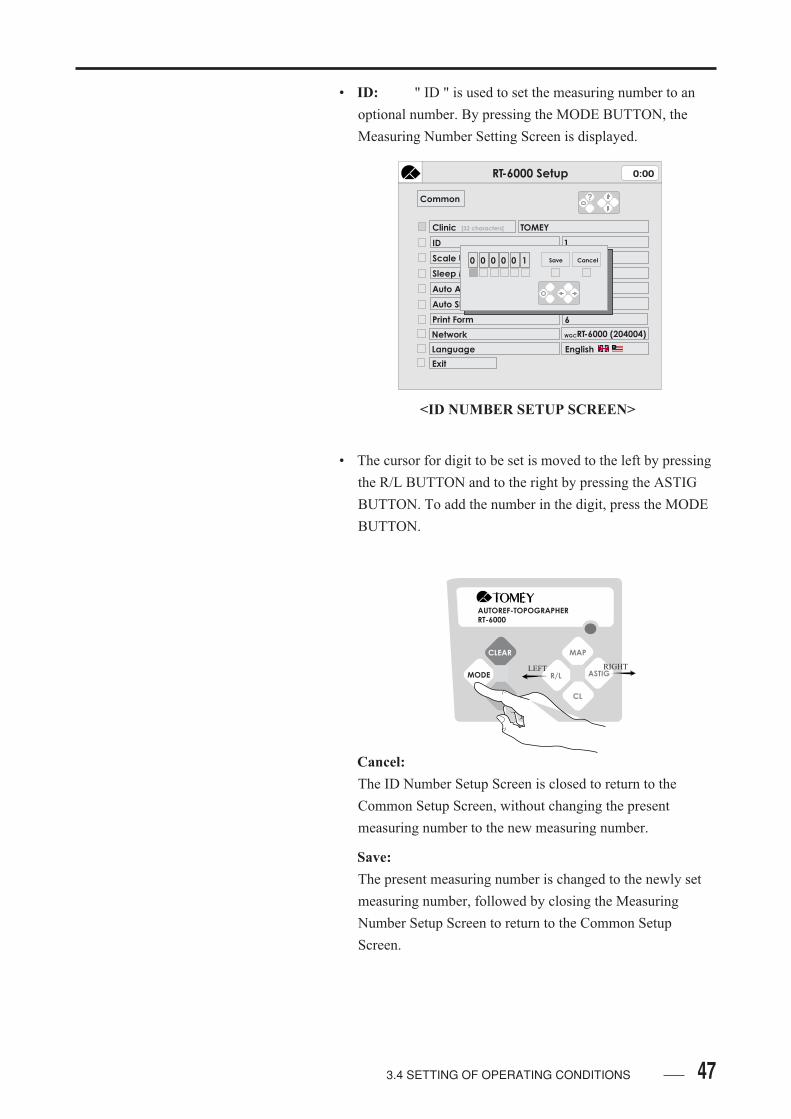
• ID: " ID " is used to set the measuring number to an
optional number. By pressing the MODE BUTTON, the
Measuring Number Setting Screen is displayed.
• The cursor for digit to be set is moved to the left by pressing
the R/L BUTTON and to the right by pressing the ASTIG
BUTTON. To add the number in the digit, press the MODE
BUTTON.
Cancel:
The ID Number Setup Screen is closed to return to the
Common Setup Screen, without changing the present
measuring number to the new measuring number.
Save:
The present measuring number is changed to the newly set
measuring number, followed by closing the Measuring
Number Setup Screen to return to the Common Setup
Screen.
<ID NUMBER SETUP SCREEN>
AUTOREF-TOPOGRAPHERRT-6000
CLEAR
MODE
MAP
R/L ASTIG
CL
LEFT RIGHT
3.4 SETTING OF OPERATING CONDITIONS
RT-6000 Setup 0:00
Common
Clinic
Exit
TOMEY[32 characters]
ID
Scale Unit
Sleep Mode[Disabled/5mm/10mm]
1
mm
5 min
Auto Alignment
Auto Shot
Print Form
Enabled
Enabled
Network
6
RT-6000 (204004)
[diopter / mm]
WGC
Language English
?
Save Cancel0 0 0 0 0 1

48
• SCALE UNIT:For " Scale Unit ", select " Diopter " or
" mm ", which are used for common purposes by
Keratometer and Topography.
• SLEEP MODE: For " Sleep Mode Start ", select the
time to start the Sleep Mode from " NO ", " 5 min. ",
" 10 min. " ( See 1.3 Glossary ).
• AUTO ALIGNMENT: For " Auto Alignment " ( See
1.3 Glossary ), select " ENABLED " or " DISABLED ".
Enabled:
Changing to the Measuring Screen starts measurement state
with Auto Alignment as always turned ON. Measurement
can be turned OFF with the buttons displayed in the
Measurement Screen.
Disabled:
Changing to the Measuring Screen starts measurement state
with Auto Alignment as alwasy turned OFF. Measurement
can be turned ON with the button displayed in the
Measurement Screen.
• AUTO SHOT: For " Auto Shot " ( See 1.3 GLOSSARY ),
select " ENABLED " or " DISABLED ".
Enabled
Changing to the Measuring Screen starts measurement state
with Auto Shot as always turned ON. Measurement can be
turned OFF with the buttons displayed in the Measurement
Screen.
Disabled:
Changing to the Measuring Screen starts measurement state
with Auto Shot as as always turned OFF. Measurement can
be turned ON with the button displayed in the Measurement
Screen.
• Move the cursor to " Exit " and press the MODE
BUTTON, the Common Items Setting Screen is closed to
return to the Setting Screen.
3.4 SETTING OF OPERATING CONDITIONS
493.4 SETTING OF OPERATING CONDITIONS
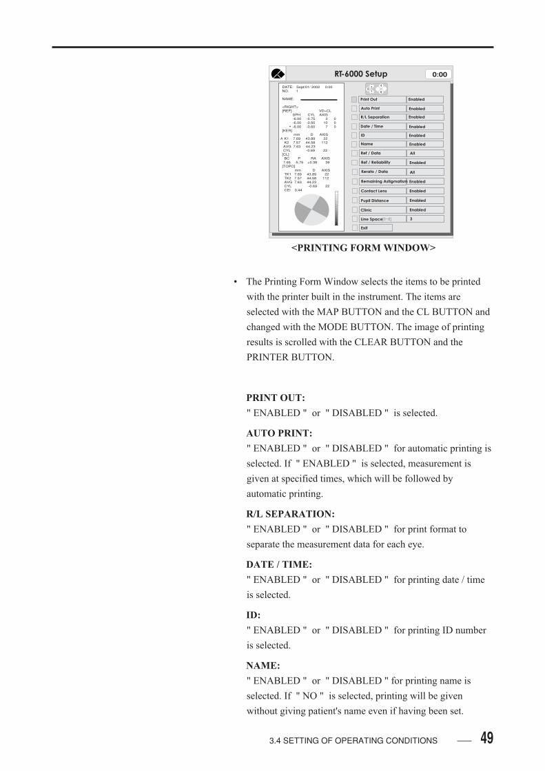
• The Printing Form Window selects the items to be printed
with the printer built in the instrument. The items are
selected with the MAP BUTTON and the CL BUTTON and
changed with the MODE BUTTON. The image of printing
results is scrolled with the CLEAR BUTTON and the
PRINTER BUTTON.
PRINT OUT:
" ENABLED " or " DISABLED " is selected.
AUTO PRINT:
" ENABLED " or " DISABLED " for automatic printing is
selected. If " ENABLED " is selected, measurement is
given at specified times, which will be followed by
automatic printing.
R/L SEPARATION:
" ENABLED " or " DISABLED " for print format to
separate the measurement data for each eye.
DATE / TIME:
" ENABLED " or " DISABLED " for printing date / time
is selected.
ID:
" ENABLED " or " DISABLED " for printing ID number
is selected.
NAME:
" ENABLED " or " DISABLED " for printing name is
selected. If " NO " is selected, printing will be given
without giving patient's name even if having been set.
<PRINTING FORM WINDOW>
RT-6000 Setup 0:00
Print Out Enabled
Auto Print
Date / Time
ID
Name
Ref / Data
Ref / Reliability
Kerato / Data
Remaining Astigmatism
Contact Lens
Pupil Distance
Clinic
Exit
Enabled
Enabled
Enabled
Enabled
All
Enabled
Enabled
Enabled
Line Space[0~8]
Enabled
Enabled
All
3
S
S
R/L Separation Enabled
DATE: Sept/01/ 2002 0:00 NO. 1 NAME: <RIGHT> [REF] VD=CL SPH CYL AXIS -6.00 -0.75 3 0 -6.00 -0.50 10 0 -6.00 -0.60 7 0 [KER] mm D AXIS K1 7.69 43.89 22 K2 7.57 44.58 112 AVG 7.63 44.23 CYL -0.69 22 [CL] BC P RA AXIS 7.65 -5.75 +0.38 39 [TOPO] mm D AXIS TK1 7.69 43.89 22 TK2 7.57 44.58 112 AVG 7.63 44.23 CYL -0.69 22 CEI 0.44
*
A
50
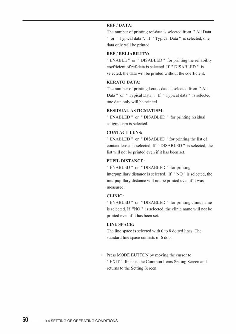
REF / DATA:
The number of printing ref-data is selected from " All Data
" or " Typical data ". If " Typical Data " is selected, one
data only will be printed.
REF / RELIABILITY:
" ENABLE " or " DISABLED " for printing the reliability
coefficient of ref-data is selected. If " DISABLED " is
selected, the data will be printed without the coefficient.
KERATO DATA:
The number of printing kerato-data is selected from " All
Data " or " Typical Data ". If " Typical data " is selected,
one data only will be printed.
RESIDUAL ASTIGMATISM:
" ENABLED " or " DISABLED " for printing residual
astigmatism is selected.
CONTACT LENS:
" ENABLED " or " DISABLED " for printing the list of
contact lenses is selected. If " DISABLED " is selected, the
list will not be printed even if it has been set.
PUPIL DISTANCE:
" ENABLED " or " DISABLED " for printing
interpupillary distance is selected. If " NO " is selected, the
interpupillary distance will not be printed even if it was
measured.
CLINIC:
" ENABLED " or " DISABLED " for printing clinic name
is selected. If "NO " is selected, the clinic name will not be
printed even if it has been set.
LINE SPACE:
The line space is selected with 0 to 8 dotted lines. The
standard line space consists of 6 dots.
• Press MODE BUTTON by moving the cursor to
" EXIT " finishes the Common Items Setting Screen and
returns to the Setting Screen.
3.4 SETTING OF OPERATING CONDITIONS

513.4 SETTING OF OPERATING CONDITIONS
3.4.7 SETTING OF NETWORK COMMUNICATION ( LAN CONNECTION )
• The data communication is possible with LAN. With LAN
connection, Refractometer / Keraometer ( CSV ) and
Topography mire and map image ( TIFF / PCX / JPEG )
under ID number as file name.
The data communicaion is done at the same ime with " Print "
operation. So RT-6000 send data when " Auto Print is done
" and " Push Print Button ". Topography image send out
when image appear on the monitor and over written as map
will switched.
• CONFIRMATION OF NETWORK NAME
In this term, confirm network name saved in RT-6000.
Press hold the MODE BUTTON to enter the Mode Screen.
Press the ASTIG BUTTON to enter Setup Screen.
Ref-Keratometer VD=CL
LeftAuto Shot
Auto Alignment
1 / 9 / 02
0:00
1 s C A N PD
K1 K2 AV( ) ( ) N
Clear
K
AA
IOL / CAT
T
AS
?

52
Press MAP BUTTON or CL BUTTON to move the cursor
and enter Common Setup Screen.
The name at immediate right of " Network " (RT-6000
(******)) is network name for this instruments. The name
will not change except intentionally setting change have
been done. This is requirement checking process so please
do so.
3.4 SETTING OF OPERATING CONDITIONS
RT-6000 Setup 0:00
Common
Clinic
Exit
TOMEY[32 characters]
ID
Scale Unit
Sleep Mode[Disabled/5mm/10mm]
1
mm
5 min
Auto Alignment
Auto Shot
Print Form
Enabled
Enabled
Network
6
RT-6000 (204004)
[diopter / mm]
WGC
Language English
?
RT-6000 Setup 0:00
Ref / Keratometer
Topography
Data / Time
Contact Lens List
Common
Information
Exit
533.4 SETTING OF OPERATING CONDITIONS
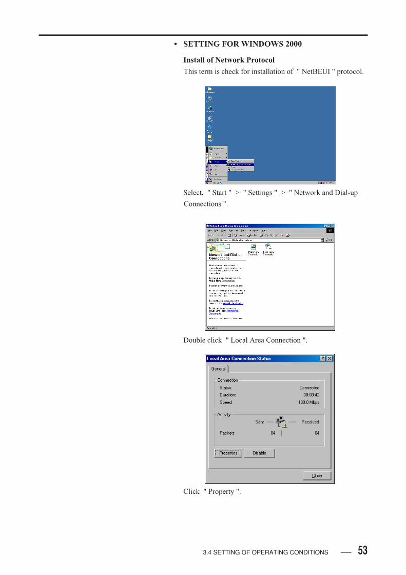
• SETTING FOR WINDOWS 2000
Install of Network Protocol
This term is check for installation of " NetBEUI " protocol.
Select, " Start " > " Settings " > " Network and Dial-up
Connections ".
Double click " Local Area Connection ".
Click " Property ".

54 3.4 SETTING OF OPERATING CONDITIONS
If "Net BEUI " protocol is available for LAN card, you do
not need to install " Net BEUI " protocol. So click " cancel "
buton to exit.
Click "Install ".
55
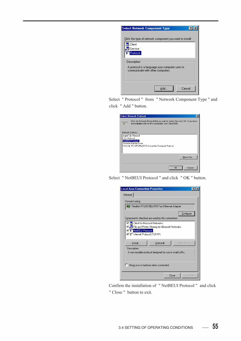
Select " Protocol " from " Network Component Type " and
click " Add " button.
Select " NetBEUI Protocol " and click " OK " button.
Confirm the installation of " NetBEUI Protocol " and click
" Close " button to exit.
3.4 SETTING OF OPERATING CONDITIONS
56 3.4 SETTING OF OPERATING CONDITIONS
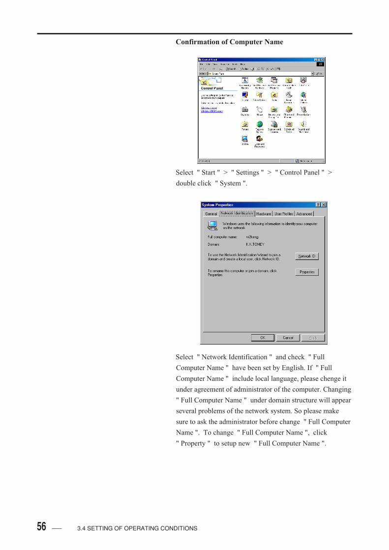
Confirmation of Computer Name
Select " Start " > " Settings " > " Control Panel " >
double click " System ".
Select " Network Identification " and check " Full
Computer Name " have been set by English. If " Full
Computer Name " include local language, please chenge it
under agreement of administrator of the computer. Changing
" Full Computer Name " under domain structure will appear
several problems of the network system. So please make
sure to ask the administrator before change " Full Computer
Name ". To change " Full Computer Name ", click
" Property " to setup new " Full Computer Name ".
57
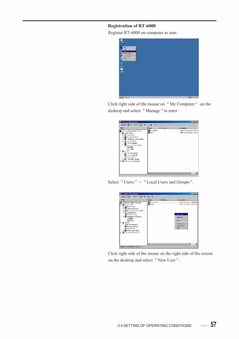
Registration of RT-6000
Register RT-6000 on computer as user.
Click right side of the mouse on " My Computer " on the
desktop and select " Manage " to enter
Select " Users " > " Local Users and Groups ".
Click right side of the mouse on the right side of the screen
on the desktop and select " New User ".
3.4 SETTING OF OPERATING CONDITIONS
58 3.4 SETTING OF OPERATING CONDITIONS
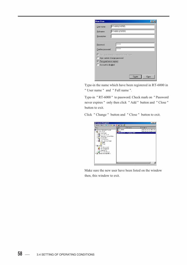
Type-in the name which have been registered in RT-6000 in
" User name " and " Full name ".
Type-in " RT-6000 " to password. Check mark on " Password
never expires " only then click " Add " button and " Close "
button to exit.
Click " Change " button and " Close " button to exit.
Make sure the new user have been listed on the window
then, this window to exit.

593.4 SETTING OF OPERATING CONDITIONS
Creation of Shared Folder
Create shared folder in C drive. The name of the folder
should be:
1). Around eight characters
2). Characters must be English alphabet or numbers.
3). No space between charactors
Select the folder and click right side of the mouse. Then,
select " Shearing ".
There is two types of securities: with security tab and
without security tab. It depends on the drive format types
( NTFS or FAT32 ). The setting of shared folder is different
in each case.
With Security Tab
Select " Share this folder " and click " Apply " and
" OK " button to exit.

60 3.4 SETTING OF OPERATING CONDITIONS
The name of permissions should be " Everyone " and delete
all other names. Set the permission as " Full Control " and
click " OK " button to exit.
Click " Apply " button.

61
Select " Security " Tab and select " Add " button.
When this screen appear, please click " Cancel " button to
exit.
Confirm the " Look in " have same name as current
computer name. Scroll the list of name and select " RT-
6000 (******). Then, click " Add " button " and " OK "
button to exit.
3.4 SETTING OF OPERATING CONDITIONS
62 3.4 SETTING OF OPERATING CONDITIONS
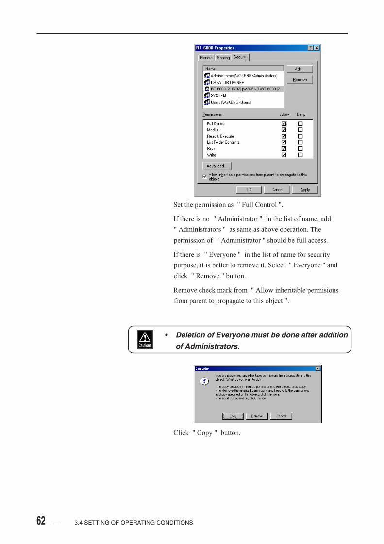
Set the permission as " Full Control ".
If there is no " Administrator " in the list of name, add
" Administrators " as same as above operation. The
permission of " Administrator " should be full access.
If there is " Everyone " in the list of name for security
purpose, it is better to remove it. Select " Everyone " and
click " Remove " button.
Remove check mark from " Allow inheritable permisions
from parent to propagate to this object ".
• Deletion of Everyone must be done after additionof Administrators.
Click " Copy " button.
633.4 SETTING OF OPERATING CONDITIONS
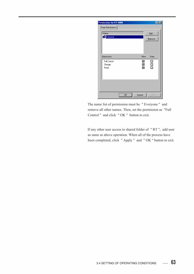
The name list of permission must be " Everyone " and
remove all other names. Then, set the permission as "Full
Control " and click " OK " button to exit.
If any other user access to shared folder of " RT ", add user
as same as above operation. When all of the process have
been completed, click " Apply " and " OK " button to exit.

64 3.4 SETTING OF OPERATING CONDITIONS
Without Security Tab
Select " Share this folder " and click " Apply " and
" OK " button to enter " Permission " screen. Then, press
" Add " button.
Confirm the " Look in " have same name as current
computer name. Scroll the list of name and select " RT-
6000 (******). Then, click " Add " button " and " OK "
button to exit.
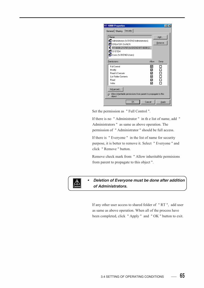
653.4 SETTING OF OPERATING CONDITIONS
Set the permission as " Full Control ".
If there is no " Administrator " in th e list of name, add "
Administrators " as same as above operation. The
permission of " Administrator " should be full access.
If there is " Everyone " in the list of name for security
purpose, it is better to remove it. Select " Everyone " and
click " Remove " button.
Remove check mark from " Allow inheritable permisions
from parent to propagate to this object ".
• Deletion of Everyone must be done after additionof Administrators.
If any other user access to shared folder of " RT ", add user
as same as above operation. When all of the process have
been completed, click " Apply " and " OK " button to exit.

66 3.4 SETTING OF OPERATING CONDITIONS
• It might take a while to do data communication, ifthere is a time-group between previous commu-nications and last one.
• If you would like to improve this delay, pleasechange setting of registry.
• This delay depends on normal computer settingthat disconnects communication when there isno communication for a while.
• This delay is improved by changing of registry.
• To change registry may be a cause of severalproblem for the computer. Please change regis-try under agreement of the computer administra-tor.

673.4 SETTING OF OPERATING CONDITIONS
• SETTING FOR WINDOWS XP HOME EDITION
• All setting process should be done under log-ging-on the computer as an administrator.
Install of Network Protocol
The " NetBEUI Protocol " have not been installed in Win-
dows XP so please install the "NetBEUI Protocol " to com-
municate with RT-6000 properly.
First of all, copy required files to system file for install.
Insert install disk of " NetBEUI Protocol " and open it.
double click " nbcopy.bat " and do it (.bat may not
displayed. It is depend on theng).
Confirm the system folder and if it is OK, press some key to
continue next process. If correct system folder is not
selected, copy this file by manual follow by the instruction
on the next page.
When the process completed, press any keys to exit from the
screen. If there is any problems to copy the ile, please try to
install as manual.

68 3.4 SETTING OF OPERATING CONDITIONS
Manual Copy
Press " Ctrl + C " to exit.
When the mesage " Do you finish this patch job? " is
appear, press " Y " and " Enter " key.
To install NetBEUI protocol, copy " NBF.SYS " and
" NETNBF.INF " to below folder.
" NBF.SYS " >>> C:\WINDOWS\SYSTEM32\DRIVERS
" NETNBF.INF " >>> C:\WINDOWS\INF
After install, close the display of " NetBEUI Protocol "
install disk.
When the file copies have been done, install " NetBEUI
Protocol " and select " Start " > " Control Panel ".
Select " Network and Internet Connections ".
Select " Network Connections ".
693.4 SETTING OF OPERATING CONDITIONS
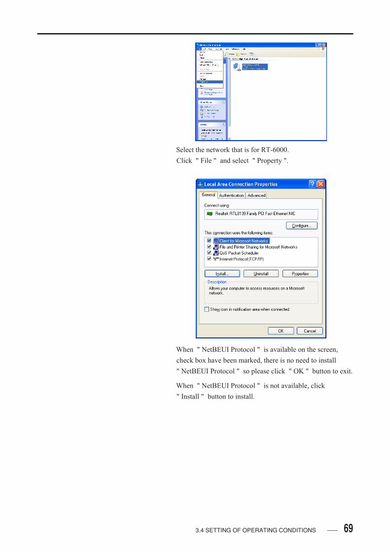
Select the network that is for RT-6000.
Click " File " and select " Property ".
When " NetBEUI Protocol " is available on the screen,
check box have been marked, there is no need to install
" NetBEUI Protocol " so please click " OK " button to exit.
When " NetBEUI Protocol " is not available, click
" Install " button to install.

70 3.4 SETTING OF OPERATING CONDITIONS
Select " Protocol " and click " Add " button.
Select " NetBEUI Protocol " and click " OK " button.
The " NetBEUI Protocol " is available so click " Close "
button to exit.
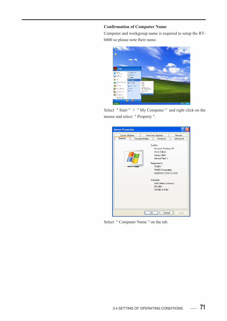
713.4 SETTING OF OPERATING CONDITIONS
Confirmation of Computer Name
Computer and workgroup name is required to setup the RT-
6000 so please note their name.
Select " Start " > " My Computer " and right click on the
mouse and select " Property ".
Select " Computer Name " on the tab.

72 3.4 SETTING OF OPERATING CONDITIONS
When " Full computer name " is English one byte and
around 8 characters, there is no need to change computer
name.
• Name of " Ful l computer name " and" Workgroup " is requirement to be set.
Click " Chnage " button to change " Full computer name ".
To change " Full computer name " under domain structure
will be several problem of the network. So please ask this
setup process to your PC administrator.
• The " Full computer name " cannot be include" period ".
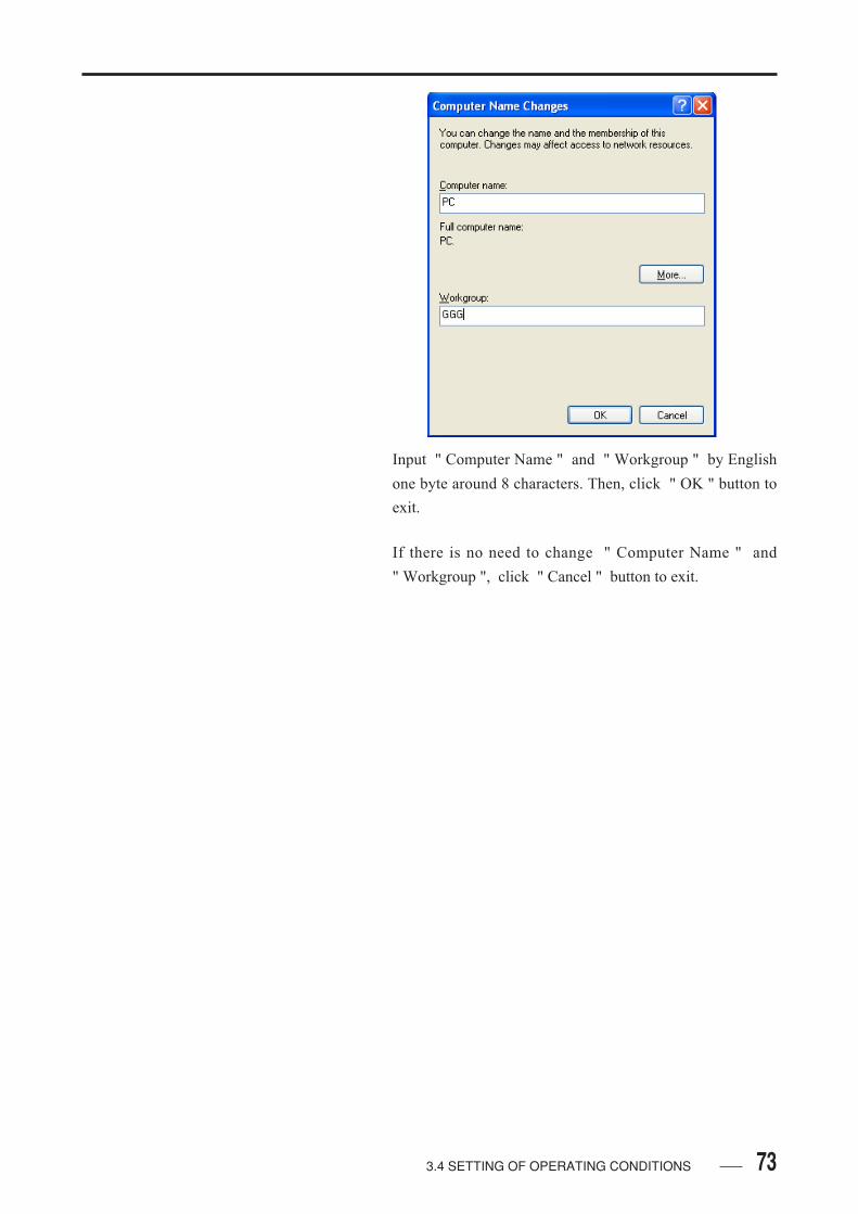
733.4 SETTING OF OPERATING CONDITIONS
Input " Computer Name " and " Workgroup " by English
one byte around 8 characters. Then, click " OK " button to
exit.
If there is no need to change " Computer Name " and
" Workgroup ", click " Cancel " button to exit.
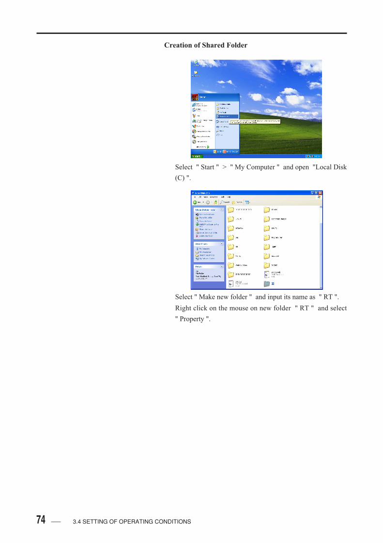
74 3.4 SETTING OF OPERATING CONDITIONS
Creation of Shared Folder
Select " Start " > " My Computer " and open "Local Disk
(C) ".
Select " Make new folder " and input its name as " RT ".
Right click on the mouse on new folder " RT " and select
" Property ".
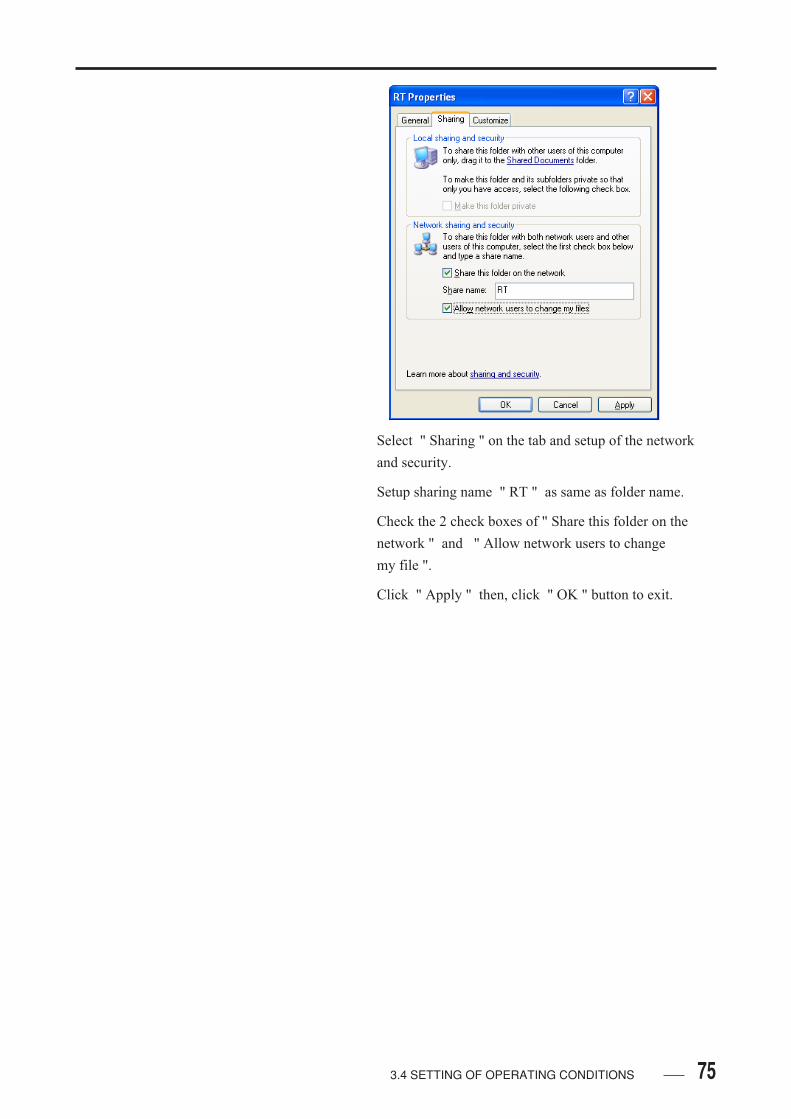
75
Select " Sharing " on the tab and setup of the network
and security.
Setup sharing name " RT " as same as folder name.
Check the 2 check boxes of " Share this folder on the
network " and " Allow network users to change
my file ".
Click " Apply " then, click " OK " button to exit.
3.4 SETTING OF OPERATING CONDITIONS

76 3.4 SETTING OF OPERATING CONDITIONS
• SETTING FOR WINDOWS XP PROFESSIONAL
EDITION
• All setting process should be done under log-ging-on the computer as an administrator.
Confirmaion of Computer Environment
Select " Start " > " My Computer " and right click on
the mouse. Then, select " Property ".
Select " Computer Name " on the tab and click
" Change" button.

773.4 SETTING OF OPERATING CONDITIONS
Check the computer that the environment is " Domain "
or " Workgroup ".
If the " Domain " member, give access permission
control on sharing folder for RT-6000 data. Click
" Cancel " button to exit and install " NetBEUI
Protocol ".
If the " Workgroup " member, click " Cancel " button
and close " Property " of system.
Select " Start " > " My Documents ".

78 3.4 SETTING OF OPERATING CONDITIONS
Select " Tools " > " Folder Options ".
Select " View " tab and make check mark on " Use
simple file sharing (Recommended) ".
If there is no check mark on " Use simple file sharing
(Recommended) ", make access permission control.
Click "Cancel " button to exit.
If there is check mark on " Use simple file sharing
(Recommended) ", don't make access permission
control. Access control become possible by change the
setting of " Use simple file sharing (Recommended) ",
but all sharing folder might be " read only " once and it
might effect current system so please ask the
administrator of the PC for more details.

793.4 SETTING OF OPERATING CONDITIONS
When the change is accepted the PC, make check mark
on " Use simple file sharing (Recommended) " and click
" Apply " button.
When the change is not acceptable, continue the data
communication setting process without changing the
setting even if access control is impossible.
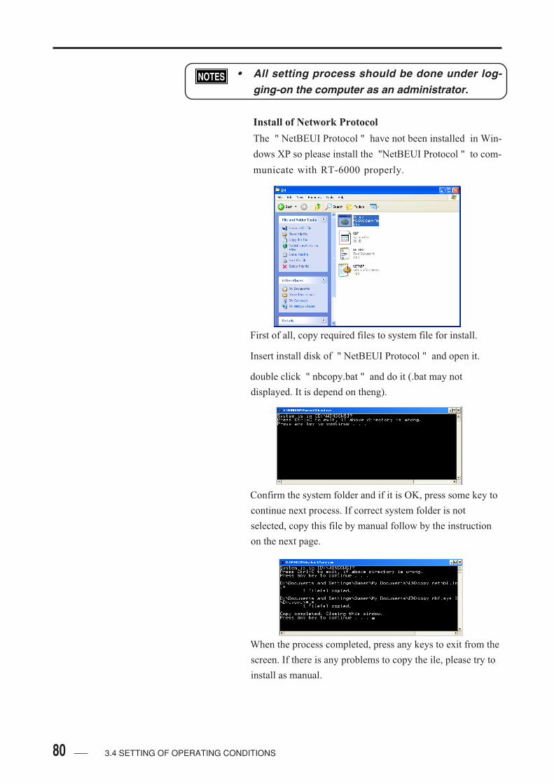
80 3.4 SETTING OF OPERATING CONDITIONS
• All setting process should be done under log-ging-on the computer as an administrator.
Install of Network Protocol
The " NetBEUI Protocol " have not been installed in Win-
dows XP so please install the "NetBEUI Protocol " to com-
municate with RT-6000 properly.
First of all, copy required files to system file for install.
Insert install disk of " NetBEUI Protocol " and open it.
double click " nbcopy.bat " and do it (.bat may not
displayed. It is depend on theng).
Confirm the system folder and if it is OK, press some key to
continue next process. If correct system folder is not
selected, copy this file by manual follow by the instruction
on the next page.
When the process completed, press any keys to exit from the
screen. If there is any problems to copy the ile, please try to
install as manual.

813.4 SETTING OF OPERATING CONDITIONS
Manual Copy
Press " Ctrl + C " to exit.
When the mesage " Do you finish this patch job? " is
appear, press " Y " and " Enter " key.
To install NetBEUI protocol, copy " NBF.SYS " and
" NETNBF.INF " to below folder.
" NBF.SYS " >>> C:\WINDOWS\SYSTEM32\DRIVERS
" NETNBF.INF " >>> C:\WINDOWS\INF
After install, close the display of " NetBEUI Protocol "
install disk.
When the file copies have been done, install " NetBEUI
Protocol " and select " Start " > " Control Panel ".
Select " Network and Internet Connections ".
Select " Network Connections ".
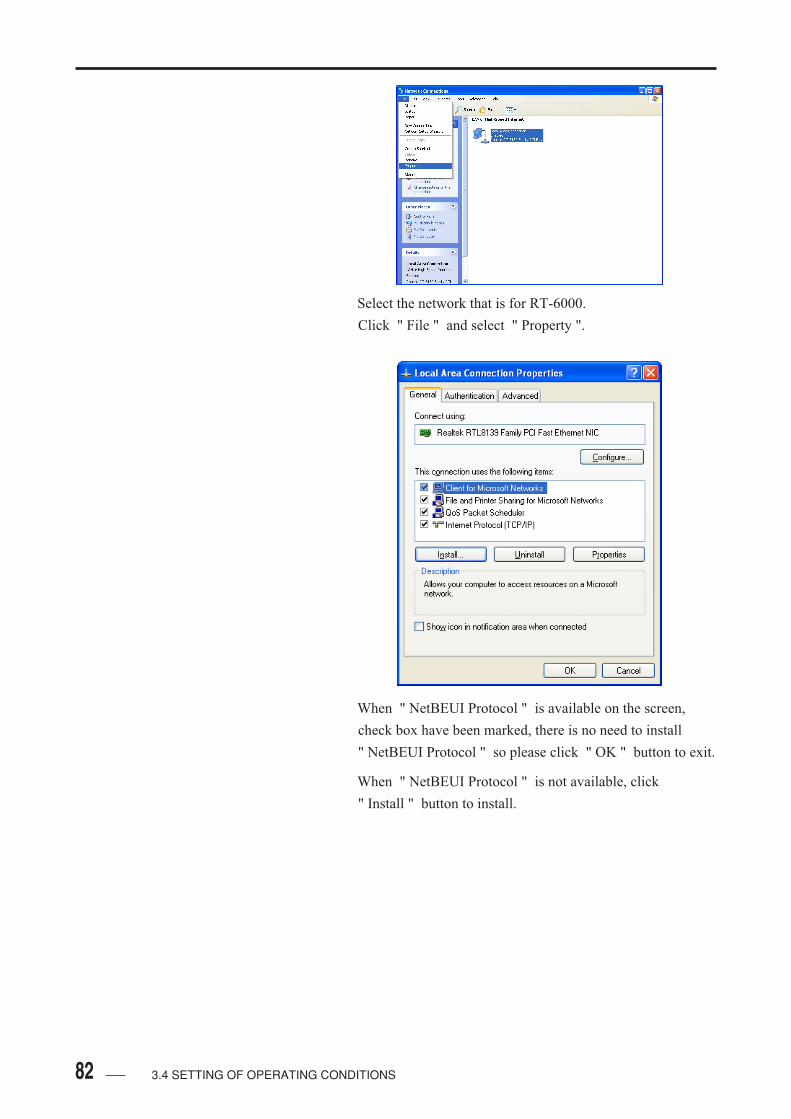
82 3.4 SETTING OF OPERATING CONDITIONS
Select the network that is for RT-6000.
Click " File " and select " Property ".
When " NetBEUI Protocol " is available on the screen,
check box have been marked, there is no need to install
" NetBEUI Protocol " so please click " OK " button to exit.
When " NetBEUI Protocol " is not available, click
" Install " button to install.
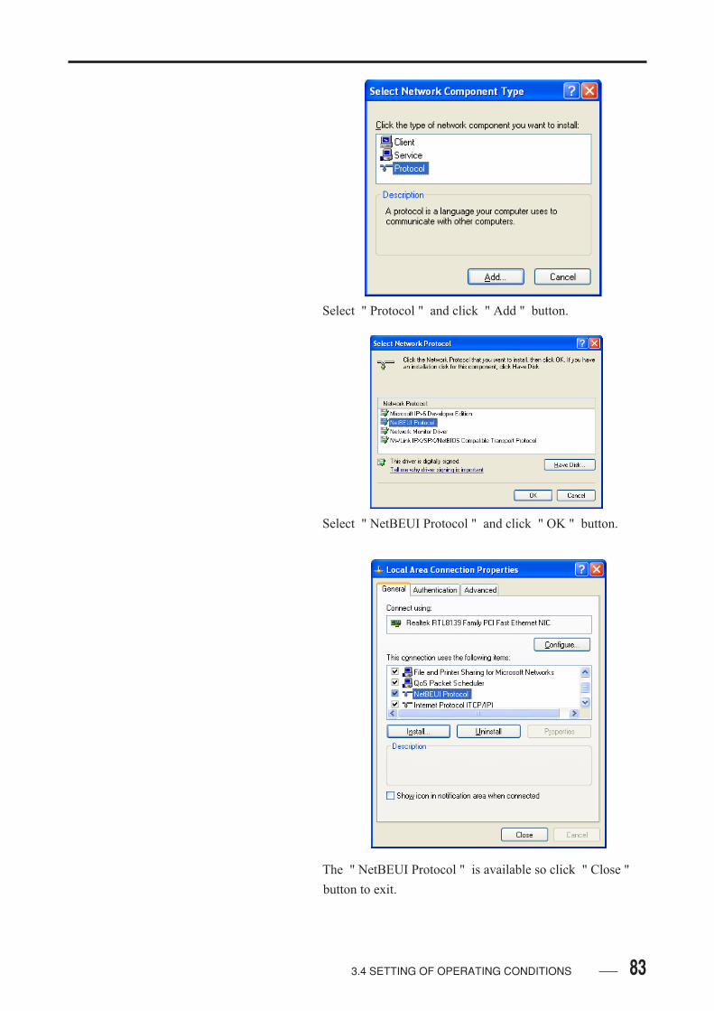
833.4 SETTING OF OPERATING CONDITIONS
Select " Protocol " and click " Add " button.
Select " NetBEUI Protocol " and click " OK " button.
The " NetBEUI Protocol " is available so click " Close "
button to exit.

84 3.4 SETTING OF OPERATING CONDITIONS
Confirmation of Computer Name
Computer and workgroup name is required to setup the RT-
6000 so please note their name.
Select " Start " > " My Computer " and right click on the
mouse and select " Property ".
Select " Computer Name " on the tab.

85
When " Full computer name " is English one byte and
around 8 characters, there is no need to change computer
name.
• Name of " Ful l computer name " and" Workgroup " is requirement to be set.
Click " Chnage " button to change " Full computer name ".
To change " Full computer name " under domain structure
will be several problem of the network. So please ask this
setup process to your PC administrator.
• The " Full computer name " cannot be include" period ".
3.4 SETTING OF OPERATING CONDITIONS

86 3.4 SETTING OF OPERATING CONDITIONS
Registration of RT-6000
Select " Start " > " My Computer " and right click on the
mouse and select " Manage ".
Select " Local Users and Groups " > " Users ".
Right click on the mouse and select " New User ".

873.4 SETTING OF OPERATING CONDITIONS
Type-in the name which have been registered in RT-
6000 in " User name " and " Full name ".
Type-in " RT-6000 " to password. Check mark on
" Password never expires " only then click " Add "
button and " Close " button to exit.
Click " Change " button and " Close " button to exit.
Make sure the new user have been listed on the
window then, close this window to exit.

88 3.4 SETTING OF OPERATING CONDITIONS
Creation of Shared Folder
Select " Start " > " My Computer " and open "Local Disk
(C) ".
Select " Make new folder " and input its name as " RT ".
Right click on the mouse on new folder " RT " and select
" Property ".
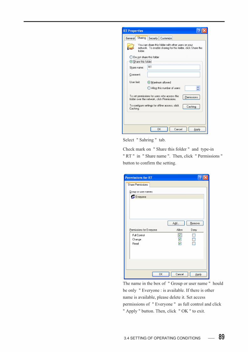
893.4 SETTING OF OPERATING CONDITIONS
Select " Sahring " tab.
Check mark on " Share this folder " and type-in
" RT " in " Share name ". Then, click " Permissions "
button to confirm the setting.
The name in the box of " Group or user name " hould
be only " Everyone : is available. If there is other
name is available, please delete it. Set access
permissions of " Everyone " as full control and click
" Apply " button. Then, click " OK " to exit.

90 3.4 SETTING OF OPERATING CONDITIONS
Click " Apply " button to exit.
Select " Security " tab. Then, click " Add " button.
Click " Advanced " button.

913.4 SETTING OF OPERATING CONDITIONS
Make sure the name of " Locations " is same with
current computer name. If there is different name have
been listed, click " Locations " button and select
current computer name. Then, search " Find now "
button.
Select RT-6000 (******) from " name " list and click
" OK " button. Then, check the bottom box with
correct name, click " OK " to exit.
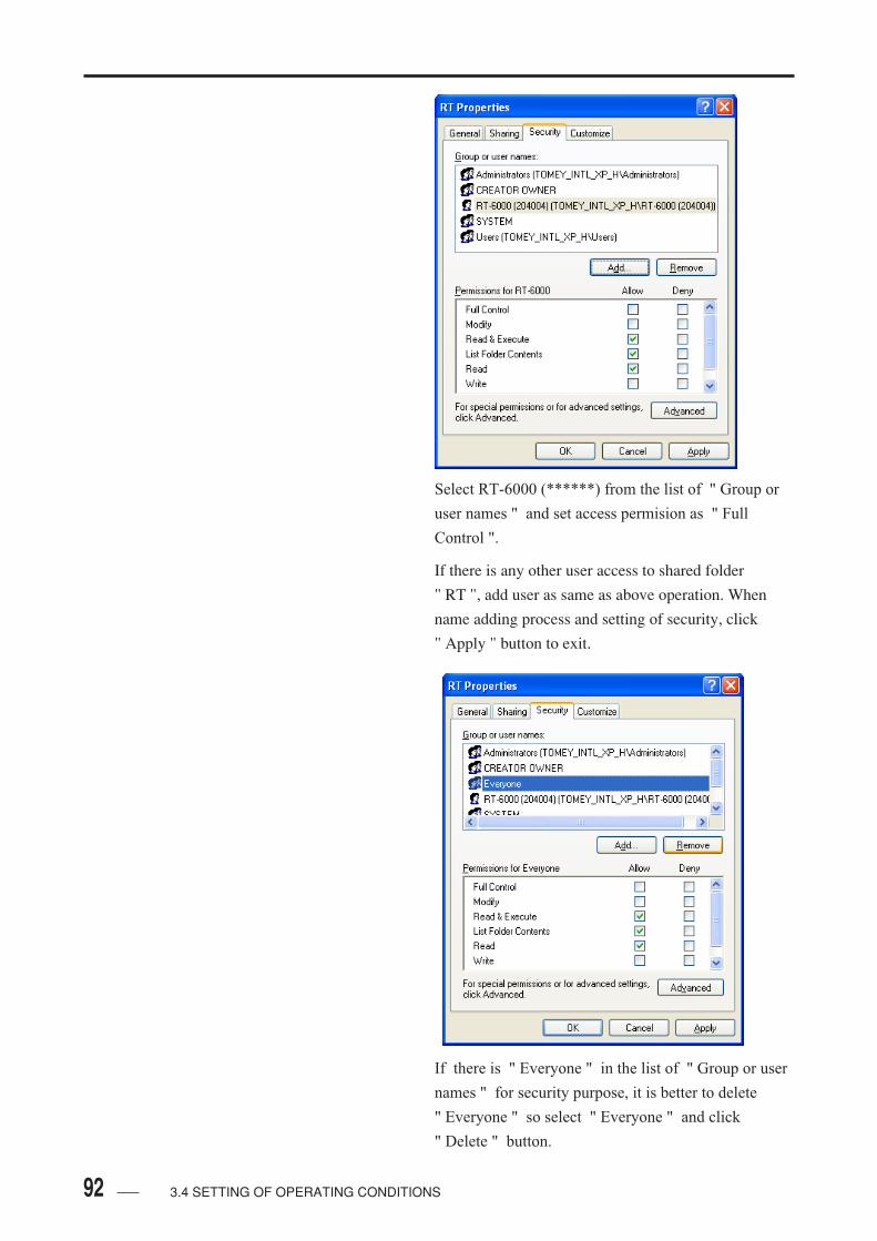
92 3.4 SETTING OF OPERATING CONDITIONS
Select RT-6000 (******) from the list of " Group or
user names " and set access permision as " Full
Control ".
If there is any other user access to shared folder
" RT ", add user as same as above operation. When
name adding process and setting of security, click
" Apply " button to exit.
If there is " Everyone " in the list of " Group or user
names " for security purpose, it is better to delete
" Everyone " so select " Everyone " and click
" Delete " button.
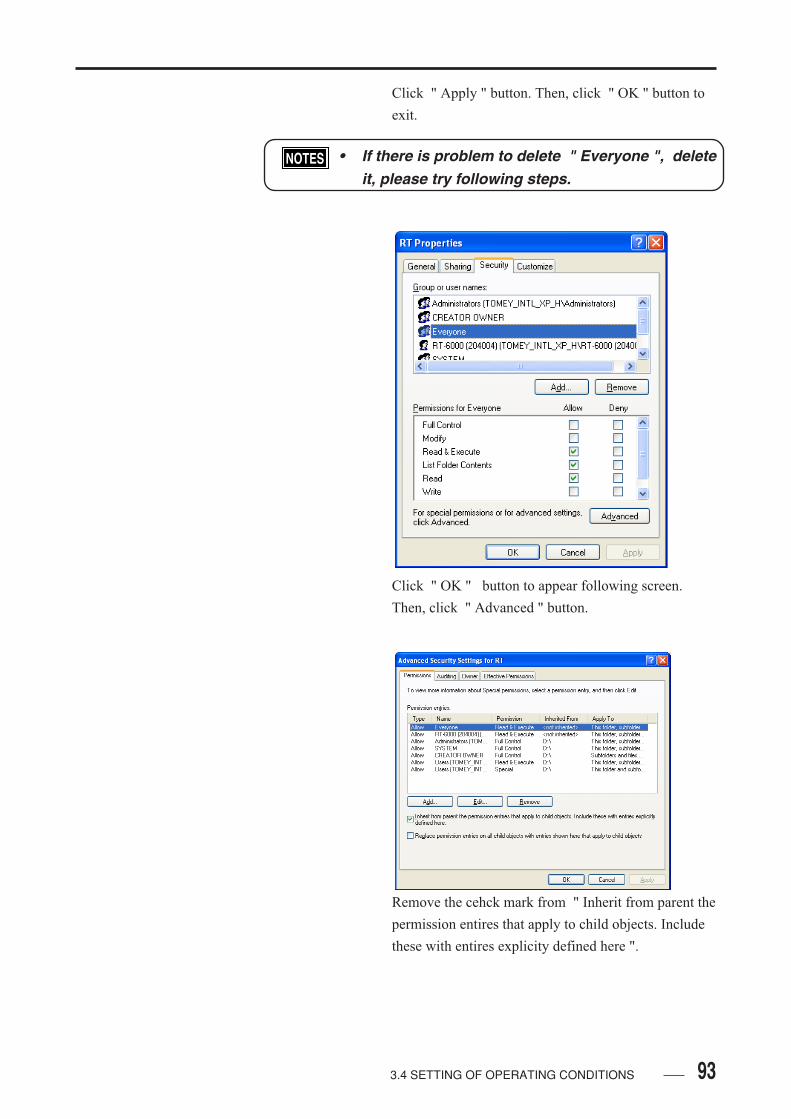
93
Click " Apply " button. Then, click " OK " button to
exit.
• If there is problem to delete " Everyone ", deleteit, please try following steps.
Click " OK " button to appear following screen.
Then, click " Advanced " button.
Remove the cehck mark from " Inherit from parent the
permission entires that apply to child objects. Include
these with entires explicity defined here ".
3.4 SETTING OF OPERATING CONDITIONS

94 3.4 SETTING OF OPERATING CONDITIONS
Click " Copy " button for the security messsage.
Select " Evryone " and click " Delete " button.
Click " Apply " button. Then " OK " button to setup
the setting.
Click " OK " button to exit.
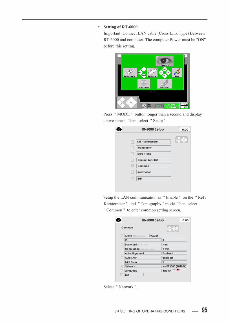
95
• Setting of RT-6000
Important: Connect LAN cable (Cross Link Type) Between
RT-6000 and computer. The computer Power must be "ON"
before this setting.
Press " MODE " button longer than a second and display
above screen. Then, select " Setup ".
Setup the LAN communication as " Enable " on the " Ref /
Keratometer " and " Topography " mode. Then, select
" Common " to enter common setting screen.
Select " Network ".
3.4 SETTING OF OPERATING CONDITIONS
RT-6000 Setup 0:00
Ref / Keratometer
Topography
Data / Time
Contact Lens List
Common
Information
Exit
RT-6000 Setup 0:00
Common
Clinic
Exit
TOMEY[32 characters]
ID
Scale Unit
Sleep Mode[Disabled/5mm/10mm]
1
mm
5 min
Auto Alignment
Auto Shot
Print Form
Enabled
Enabled
Network
6
RT-6000 (204004)
[diopter / mm]
WGC
Language English
?
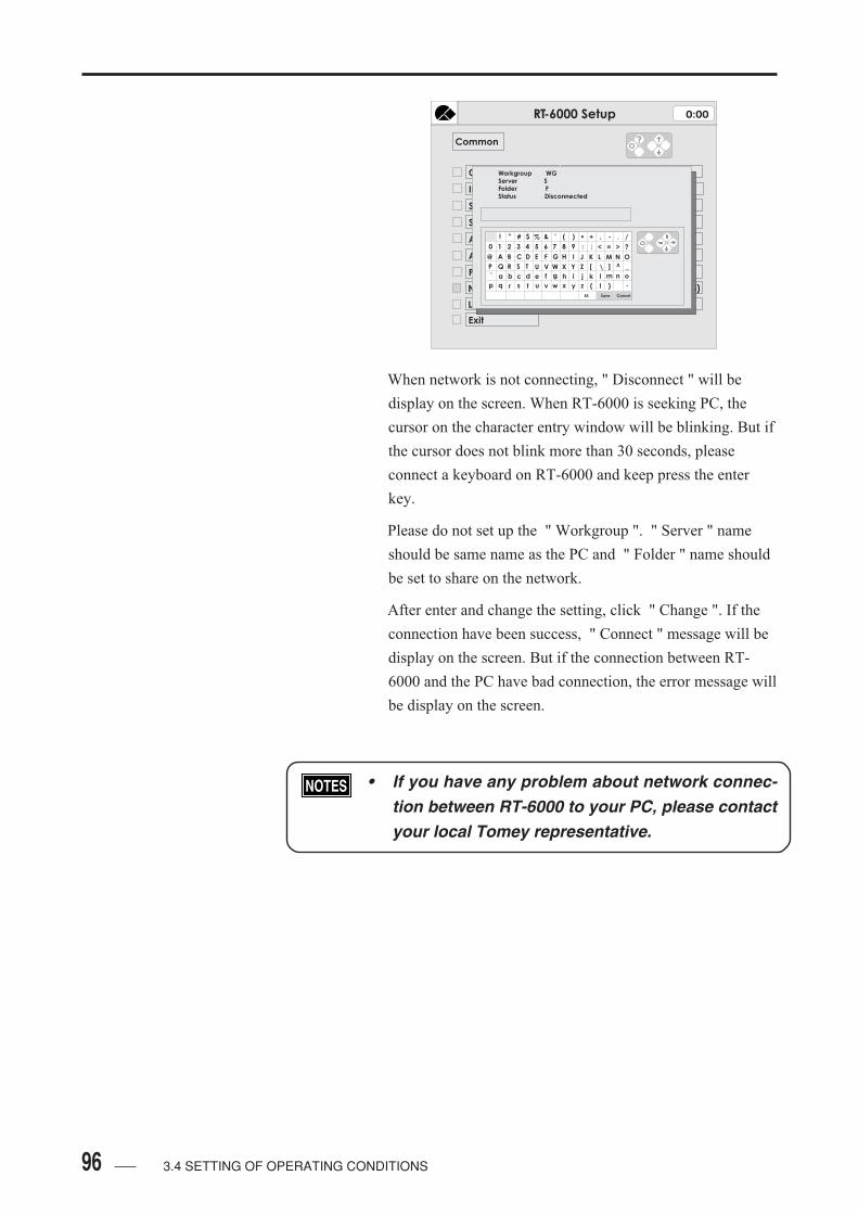
96
When network is not connecting, " Disconnect " will be
display on the screen. When RT-6000 is seeking PC, the
cursor on the character entry window will be blinking. But if
the cursor does not blink more than 30 seconds, please
connect a keyboard on RT-6000 and keep press the enter
key.
Please do not set up the " Workgroup ". " Server " name
should be same name as the PC and " Folder " name should
be set to share on the network.
After enter and change the setting, click " Change ". If the
connection have been success, " Connect " message will be
display on the screen. But if the connection between RT-
6000 and the PC have bad connection, the error message will
be display on the screen.
• If you have any problem about network connec-tion between RT-6000 to your PC, please contactyour local Tomey representative.
3.4 SETTING OF OPERATING CONDITIONS
RT-6000 Setup 0:00
Common
Clinic
Exit
TOMEY[32 characters]
ID
Scale Unit
Sleep Mode[Disabled/5mm/10mm]
1
mm
5 min
Auto Alignment
Auto Shot
Print Form
Enabled
Enabled
Network
6
RT-6000 (204004)
[diopter / mm]
WGC
Language English
?
Workgroup WGServer SFolder FStatus Disconnected
! " # $ % & ' ( ) * + , - . /
0 1 2 3 4 5 6 7 8 9 : ; < >= ?
A B C D E F G H I J K L M N O
P Q R S T U V W X Y Z [ ] ^ _
` a b c d e f g h i j k l m n o
p q r s t u v w x y z { l }
Save CancelBS
\
@

97
RS-232C CONNECTION
Setting of RT-6000 to do data communication by RS-232C.
Press the MODE BUTTON for a few seconds, till the
MODE CHANGE SCREEN appears.
Select " Setup " on the mode change display.
Select " Ref / Keratometer " ( The RS-232C connection is
only able to send Ref / Keratometer data to the PC ).
Select " Data Communication " and select " REFTESTER "
or " COM (Format 1) " or " COM (Format 2) ".
With " COM (Format 1 ) " or " COM (Format 2) " adjust
baud rate as same as the computer setting rate. If some data
is missing while communicaion, change baud rate as fast as
possible.
3.4 SETTING OF OPERATING CONDITIONS
RT-6000 Setup 0:00
Ref / Keratometer
Topography
Data / Time
Contact Lens List
Common
Information
Exit
RT-6000 Setup 0:00
Ref/Keratometer
Vertex Distance
VD in FL Mode
Step
Cylindrical Power
Measurement
RS-232C
Exit
Contact Lens
12mm
0.25D
-
High Speed
NO
[FL/CL]
[12mm/13.5mm]
[0.12D/0.25D]
[ +/+ - / - ]
[Normal/High]
?
Data Communication Disabled
Measurement Number[R:3/5 K:1/3] R: 3 / K:3
[No /9600-38400 / REFTESTER]

98 3.4 SETTING OF OPERATING CONDITIONS
LANGUAGE
Press the MODE BUTTON for a few seconds, till the
MODE CHANGE SCREEN appears.
Setting for the languages on the display.
Select " Setup " on the mode change display.
Select " Common "
Press " MODE " button to change the languages.
- English, German, French, Italian, Portuguese, Spanish,
Russian, Chinese are available
RT-6000 Setup 0:00
Ref / Keratometer
Topography
Data / Time
Contact Lens List
Common
Information
Exit
RT-6000 Setup 0:00
Common
Clinic
Exit
TOMEY[32 characters]
ID
Scale Unit
Sleep Mode[Disabled/5mm/10mm]
1
mm
5 min
Auto Alignment
Auto Shot
Print Form
Enabled
Enabled
Network
6
RT-6000 (204004)
[diopter / mm]
WGC
Language English
?
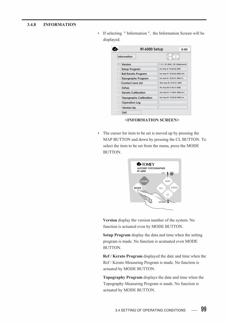
99
3.4.8 INFORMATION
• If selecting " Information ", the Information Screen will be
displayed.
• The cursor for item to be set is moved up by pressing the
MAP BUTTON and down by pressing the CL BUTTON. To
select the item to be set from the menu, press the MODE
BUTTON.
Version display the version number of the system. No
function is actuated even by MODE BUTTON.
Setup Program display the data and time when the setting
program is made. No function is acutuated even MODE
BUTTON.
Ref / Kerato Program displayed the date and time when the
Ref / Kerato Measuring Program is made. No function is
actuated by MODE BUTTON.
Topography Program displays the date and time when the
Topography Measuring Program is made. No function is
actuated by MODE BUTTON.
<INFORMATION SCREEN>
AUTOREF-TOPOGRAPHERRT-6000
CLEAR
MODE
MAP
R/L ASTIG
CL
UP
DOWN
3.4 SETTING OF OPERATING CONDITIONS
RT-6000 Setup 0:00
Information
Version
Setup Program
Ref/Kerato Program
Topography Program
Contact Lens List
Setup
Kerato Calibration
Topography Calibration
Version Up
Exit
1.13 / 3C (Ref) / 0C (Alignment)
Sun Sep 01 10:22:46 2002
Sun Sep 01 10:22:53 2002
Sun Sep 01 10:23:21 2002
Mon Sep 02 14:37:21 2002
Thu Sep 05 21:06:12 2002
Sun Sep 01 11:44:01 2002
Sun Sep 01 10:32:59 2002
Operation Log
(Op)
(T)
(Kc)
(Tn)
100
Contact Lens List displays the date and time when the
Contact Lens List is made. No function is actuated by
MODE BUTTON.
Setup displays the date and time when the Setting Items are
change. No function is actuated by MODE BUTTON.
Kerato Calibration displays the date and time when the
Calibration is given for Kerato measurement. No function is
actuated by MODE BUTTON.
Topography Calibration displays the date and time when
calibration is given for Topography Measurement. No
function is actuated by MODE BUTTON.
Operation Log prints out the recent operation records by
built-in printer by MODE BUTTON. The start, exit, mode
change, measuring condition, and errors and the operating
condition of the instrument in their time sequence are printed
out.
Exit closes the Information display Screen and return to the
Setting Screen, when moving the cursor to " Close " and
pressing the MODE BUTTON.
3.4 SETTING OF OPERATING CONDITIONS
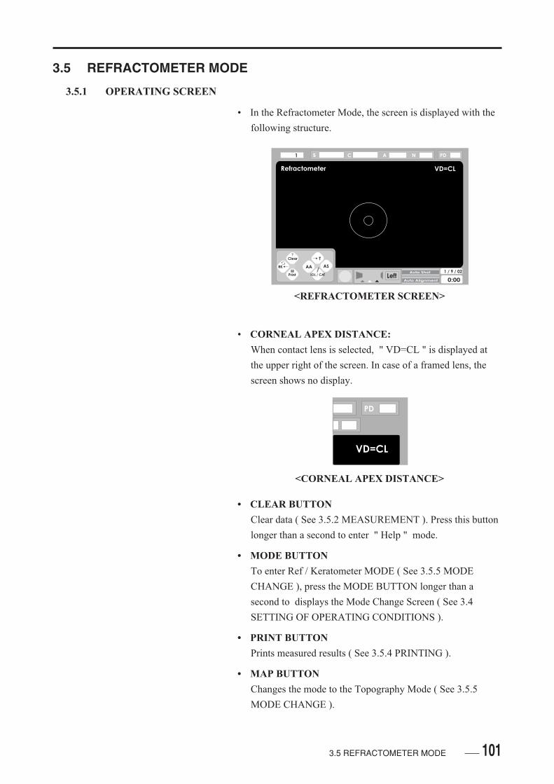
101
3.5 REFRACTOMETER MODE
3.5.1 OPERATING SCREEN
• In the Refractometer Mode, the screen is displayed with the
following structure.
• CORNEAL APEX DISTANCE:
When contact lens is selected, " VD=CL " is displayed at
the upper right of the screen. In case of a framed lens, the
screen shows no display.
• CLEAR BUTTON
Clear data ( See 3.5.2 MEASUREMENT ). Press this button
longer than a second to enter " Help " mode.
• MODE BUTTON
To enter Ref / Keratometer MODE ( See 3.5.5 MODE
CHANGE ), press the MODE BUTTON longer than a
second to displays the Mode Change Screen ( See 3.4
SETTING OF OPERATING CONDITIONS ).
• PRINT BUTTON
Prints measured results ( See 3.5.4 PRINTING ).
• MAP BUTTON
Changes the mode to the Topography Mode ( See 3.5.5
MODE CHANGE ).
<REFRACTOMETER SCREEN>
VD=CL
PD
<CORNEAL APEX DISTANCE>
Refractometer VD=CL
LeftAuto Shot
Auto Alignment
1 / 9 / 02
0:00
1 s C A N PD
Clear
RK
AA
IOL / CAT
T
AS
?
3.5 REFRACTOMETER MODE

102
• R / L BUTTON
Setup Auto Alignment ( AA ).
• ASTIGMATISM BUTTON
Setup Auto Shot ( AS ).
• CL BUTTON
The mode is changes to the Refractometer Measurement
Mode ( See 3.5.3 IOL AND CATARACT MODE ). Press of
this button long displays the Patient Name Setting Screen
( See 3.4 SETTING OF OPERATING CONDITIONS ).
3.5 REFRACTOMETER MODE

103
3.5.2 MEASUREMENT
• Make alignment ( See 3.3.4 ALIGNMENT ) and press the
MEASUREMENT BUTTON to start measurement.
• Message is displayed while measurement is in process.
• Auto Measurement is given while Auto Shot is ON.
• In this mode, three to five measurements are taken for each
eye. In the event an erroneous alignment or operation occurs
in process of measurement, repeat measurement.
<MEAUSREMENT BUTTON>
<SCREEN IN PROCESS OF MEASUREMENT>
tAuto Shot
Auto Alignment
<AUTO SHOT>
3.5 REFRACTOMETER MODE
Refractometer VD=CL
LeftAuto Shot
Auto Alignment
1 / 9 / 02
0:00
1 s C A N PD
Measure
Clear
RK
AA
IOL / CAT
T
AS
?
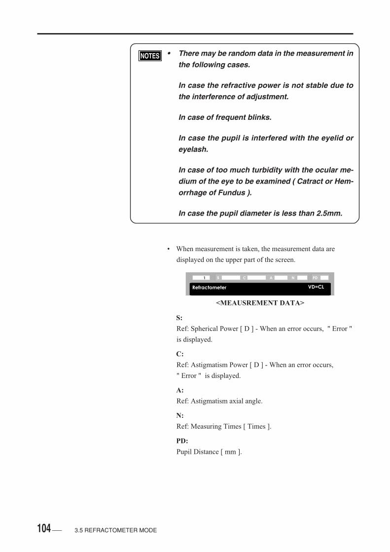
104
• There may be random data in the measurement inthe following cases.
In case the refractive power is not stable due tothe interference of adjustment.
In case of frequent blinks.
In case the pupil is interfered with the eyelid oreyelash.
In case of too much turbidity with the ocular me-dium of the eye to be examined ( Catract or Hem-orrhage of Fundus ).
In case the pupil diameter is less than 2.5mm.
• When measurement is taken, the measurement data are
displayed on the upper part of the screen.
S:
Ref: Spherical Power [ D ] - When an error occurs, " Error "
is displayed.
C:
Ref: Astigmatism Power [ D ] - When an error occurs,
" Error " is displayed.
A:
Ref: Astigmatism axial angle.
N:
Ref: Measuring Times [ Times ].
PD:
Pupil Distance [ mm ].
Refractometer VD=CL
1 s C A N PD
<MEAUSREMENT DATA>
3.5 REFRACTOMETER MODE
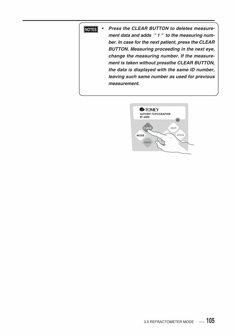
105
• Press the CLEAR BUTTON to deletes measure-ment data and adds " 1 " to the measuring num-ber. In case for the next patient, press the CLEARBUTTON. Measuring proceeding in the next eye,change the measuring number. If the measure-ment is taken without pressthe CLEAR BUTTON,the data is displayed with the same ID number,leaving such same number as used for previousmeasurement.
AUTOREF-TOPOGRAPHERRT-6000
CLEAR
MODE
MAP
R/L ASTIG
CL
3.5 REFRACTOMETER MODE
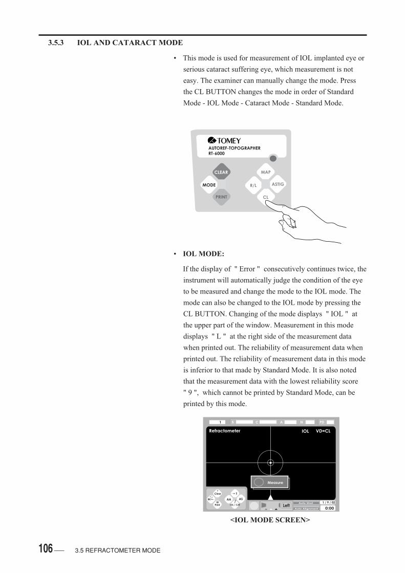
106
Refractometer VD=CL
LeftAuto Shot
Auto Alignment
1 / 9 / 02
0:00
1 s C A N PD
Measure
Clear
RK
AA
IOL / CAT
T
AS
?
IOL
<IOL MODE SCREEN>
3.5.3 IOL AND CATARACT MODE
• This mode is used for measurement of IOL implanted eye or
serious cataract suffering eye, which measurement is not
easy. The examiner can manually change the mode. Press
the CL BUTTON changes the mode in order of Standard
Mode - IOL Mode - Cataract Mode - Standard Mode.
• IOL MODE:
If the display of " Error " consecutively continues twice, the
instrument will automatically judge the condition of the eye
to be measured and change the mode to the IOL mode. The
mode can also be changed to the IOL mode by pressing the
CL BUTTON. Changing of the mode displays " IOL " at
the upper part of the window. Measurement in this mode
displays " L " at the right side of the measurement data
when printed out. The reliability of measurement data when
printed out. The reliability of measurement data in this mode
is inferior to that made by Standard Mode. It is also noted
that the measurement data with the lowest reliability score
" 9 ", which cannot be printed by Standard Mode, can be
printed by this mode.
3.5 REFRACTOMETER MODE
AUTOREF-TOPOGRAPHERRT-6000
CLEAR
MODE
MAP
R/L ASTIG
CL
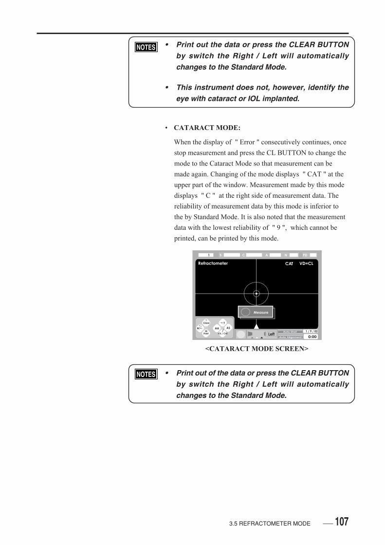
107
• Print out the data or press the CLEAR BUTTONby switch the Right / Left will automaticallychanges to the Standard Mode.
• This instrument does not, however, identify theeye with cataract or IOL implanted.
• CATARACT MODE:
When the display of " Error " consecutively continues, once
stop measurement and press the CL BUTTON to change the
mode to the Cataract Mode so that measurement can be
made again. Changing of the mode displays " CAT " at the
upper part of the window. Measurement made by this mode
displays " C " at the right side of measurement data. The
reliability of measurement data by this mode is inferior to
the by Standard Mode. It is also noted that the measurement
data with the lowest reliability of " 9 ", which cannot be
printed, can be printed by this mode.
• Print out of the data or press the CLEAR BUTTONby switch the Right / Left will automaticallychanges to the Standard Mode.
3.5 REFRACTOMETER MODE
Refractometer VD=CL
LeftAuto Shot
Auto Alignment
1 / 9 / 02
0:00
1 s C A N PD
Measure
Clear
RK
AA
IOL / CAT
T
AS
?
CAT
<CATARACT MODE SCREEN>
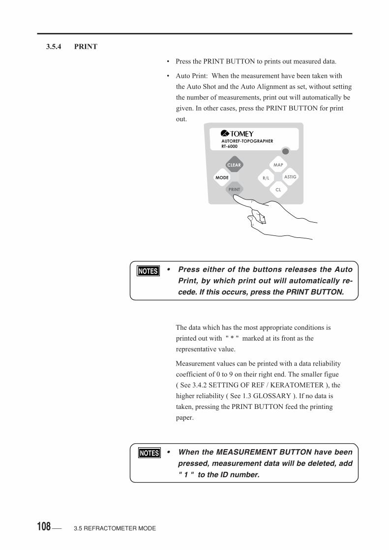
108
3.5.4 PRINT
• Press the PRINT BUTTON to prints out measured data.
• Auto Print: When the measurement have been taken with
the Auto Shot and the Auto Alignment as set, without setting
the number of measurements, print out will automatically be
given. In other cases, press the PRINT BUTTON for print
out.
• Press either of the buttons releases the AutoPrint, by which print out will automatically re-cede. If this occurs, press the PRINT BUTTON.
The data which has the most appropriate conditions is
printed out with " * " marked at its front as the
representative value.
Measurement values can be printed with a data reliability
coefficient of 0 to 9 on their right end. The smaller figue
( See 3.4.2 SETTING OF REF / KERATOMETER ), the
higher reliability ( See 1.3 GLOSSARY ). If no data is
taken, pressing the PRINT BUTTON feed the printing
paper.
• When the MEASUREMENT BUTTON have beenpressed, measurement data will be deleted, add" 1 " to the ID number.
AUTOREF-TOPOGRAPHERRT-6000
CLEAR
MODE
MAP
R/L ASTIG
CL
3.5 REFRACTOMETER MODE

109
<AN EXAMPLE OF PRINT>
• To confirm data for refractive power to be printed, press the
PRINT BUTTON longer than a second.
AUTOREF-TOPOGRAPHERRT-6000
CLEAR
MODE
MAP
R/L ASTIG
CL
<DISPLAY OF BUTTONS IN THE SCREEN>
3.5 REFRACTOMETER MODE
Representative Refractive Power
DATE: Sept/01/2002 0:00 NO. 1 NAME: <RIGHT> [REF] VD=CL SPH CYL AXIS -6.00 -0.75 3 0 -6.00 -0.50 10 0 -6.00 -0.50 7 0 <LEFT> [REF] VD=CL SPH CYL AXIS -3.75 -1.75 176 e4 -4.50 -1.75 165 0 -4.00 -1.50 7 0
PD=66mm
*
*
Error Display
Clear
RK
AA
IOL / CAT
T
AS
?
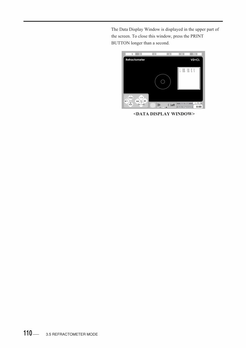
110 3.5 REFRACTOMETER MODE
The Data Display Window is displayed in the upper part of
the screen. To close this window, press the PRINT
BUTTON longer than a second.
Refractometer VD=CL
LeftAuto Shot
Auto Alignment
1 / 9 / 02
0:00
1 s C A N PD
Clear
RK
AA
IOL / CAT
T
AS
?
L +4.50 -5.25 37 0L +4.50 -5.25 37 0L* +4.50 -5.25 36 0
<DATA DISPLAY WINDOW>
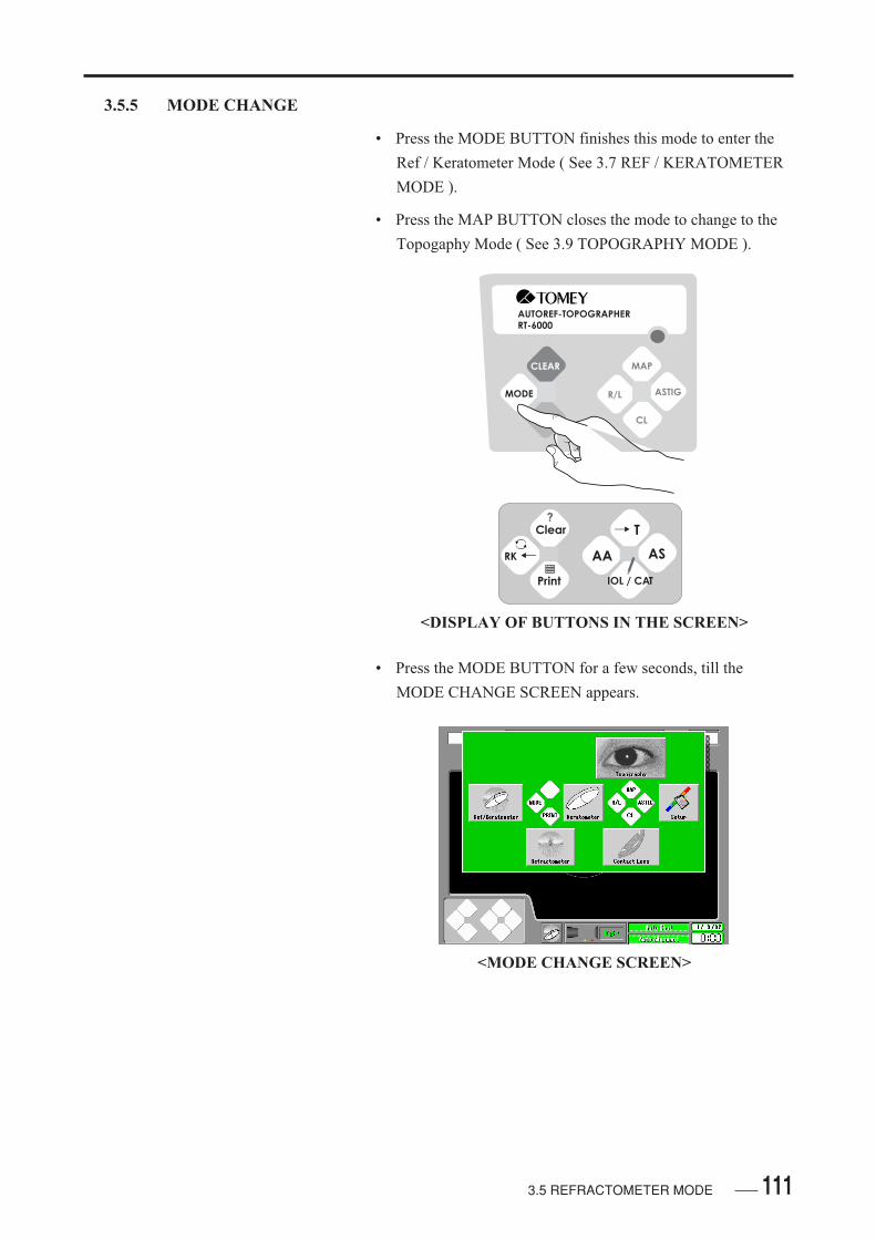
1113.5 REFRACTOMETER MODE
3.5.5 MODE CHANGE
• Press the MODE BUTTON finishes this mode to enter the
Ref / Keratometer Mode ( See 3.7 REF / KERATOMETER
MODE ).
• Press the MAP BUTTON closes the mode to change to the
Topogaphy Mode ( See 3.9 TOPOGRAPHY MODE ).
• Press the MODE BUTTON for a few seconds, till the
MODE CHANGE SCREEN appears.
AUTOREF-TOPOGRAPHER
RT-6000
CLEAR
MODE
MAP
R/L ASTIG
CL
<DISPLAY OF BUTTONS IN THE SCREEN>
<MODE CHANGE SCREEN>
Clear
RK
AA
IOL / CAT
T
AS
?
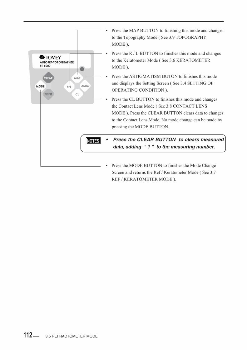
112
AUTOREF-TOPOGRAPHERRT-6000
CLEAR
MODE
MAP
R/L ASTIG
CL
• Press the MAP BUTTON to finishing this mode and changes
to the Topography Mode ( See 3.9 TOPOGRAPHY
MODE ).
• Press the R / L BUTTON to finishes this mode and changes
to the Keratometer Mode ( See 3.6 KERATOMETER
MODE ).
• Press the ASTIGMATISM BUTON to finishes this mode
and displays the Setting Screen ( See 3.4 SETTING OF
OPERATING CONDITION ).
• Press the CL BUTTON to finishes this mode and changes
the Contact Lens Mode ( See 3.8 CONTACT LENS
MODE ). Press the CLEAR BUTTON clears data to changes
to the Contact Lens Mode. No mode change can be made by
pressing the MODE BUTTON.
• Press the CLEAR BUTTON to clears measureddata, adding " 1 " to the measuring number.
• Press the MODE BUTTON to finishes the Mode Change
Screen and returns the Ref / Keratometer Mode ( See 3.7
REF / KERATOMETER MODE ).
3.5 REFRACTOMETER MODE
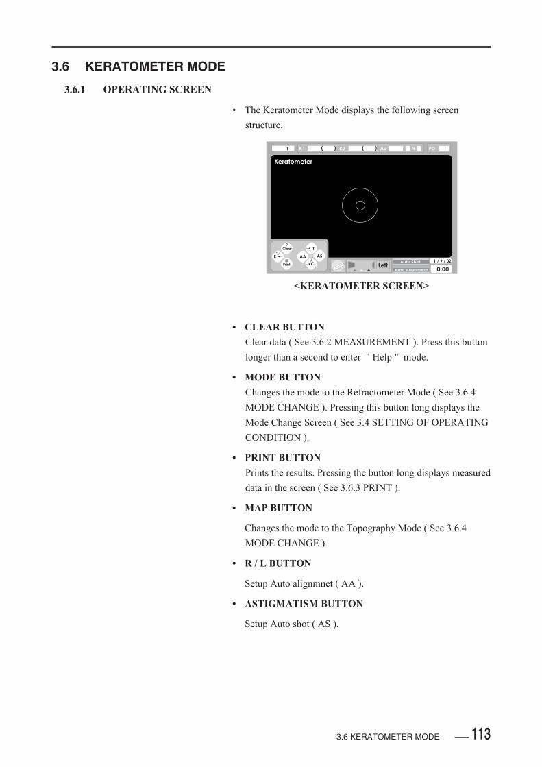
1133.6 KERATOMETER MODE
3.6 KERATOMETER MODE
3.6.1 OPERATING SCREEN
• The Keratometer Mode displays the following screen
structure.
• CLEAR BUTTON
Clear data ( See 3.6.2 MEASUREMENT ). Press this button
longer than a second to enter " Help " mode.
• MODE BUTTON
Changes the mode to the Refractometer Mode ( See 3.6.4
MODE CHANGE ). Pressing this button long displays the
Mode Change Screen ( See 3.4 SETTING OF OPERATING
CONDITION ).
• PRINT BUTTON
Prints the results. Pressing the button long displays measured
data in the screen ( See 3.6.3 PRINT ).
• MAP BUTTON
Changes the mode to the Topography Mode ( See 3.6.4
MODE CHANGE ).
• R / L BUTTON
Setup Auto alignmnet ( AA ).
• ASTIGMATISM BUTTON
Setup Auto shot ( AS ).
<KERATOMETER SCREEN>
Keratometer
LeftAuto Shot
Auto Alignment
1 / 9 / 02
0:00
1 PD
Clear
R
AA
CL
T
AS
?
K1 K2 AV( ) ( ) N
114
• CL BUTTON
The mode is changes to the Contact Lens Mode ( See 3.6.4
PRINT ). Press of this button longer than a second to
displays the Patient's Name Setting Screen ( See 3.6.1
OPERATING SCREEN ). Press the CL Button displays the
screen to change the mode to the Contact Lens Mode. Press
the CLEAR BUTTON to clears data to change the mode to
the Contact Lens Mode. No mode change is made by press
the MODE BUTTON.
• Press the CLEAR BUTTON to clears measureddata, adding " 1 " to the measuring number.
3.6 KERATOMETER MODE
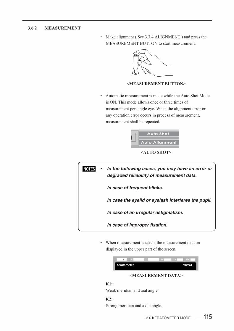
115
3.6.2 MEASUREMENT
• Make alignment ( See 3.3.4 ALIGNMENT ) and press the
MEASUREMENT BUTTON to start measurement.
• Automatic measurement is made while the Auto Shot Mode
is ON. This mode allows once or three times of
measurement per single eye. When the alignment error or
any operation error occurs in process of measurement,
measurement shall be repeated.
• In the following cases, you may have an error ordegraded reliability of measurement data.
In case of frequent blinks.
In case the eyelid or eyelash interferes the pupil.
In case of an irregular astigmatism.
In case of improper fixation.
• When measurement is taken, the measurement data on
displayed in the upper part of the screen.
K1:
Weak meridian and aial angle.
K2:
Strong meridian and axial angle.
<MEASUREMENT BUTTON>
tAuto Shot
Auto Alignment
<MEASUREMENT DATA>
3.6 KERATOMETER MODE
<AUTO SHOT>
Keratometer VD=CL
1 s C AV N PD

116
AV:
Average value of strong and weak meridians [ mm ]. The
measuring condition is displayed on the right side.
e:
Indicates inferior reliability of measurement.
E:
Indicates more inferior reliability to that with [ e ].
PD:
Interpupillary Distance.
• Press the CLEAR BUTTON to de le tesmeasuredment data, adding " 1 " to the measur-ing number. In case of proceeding in the mea-surement of the next patient without printing,press the CLEAR BUTTON
• Consective measurements of the next patientwithout print out or proceeding in the measure-ment without pressing the CLEAR BUTTON todisplays the same ID number, leave mea-surement data taken for the previous patient.
3.6 KERATOMETER MODE
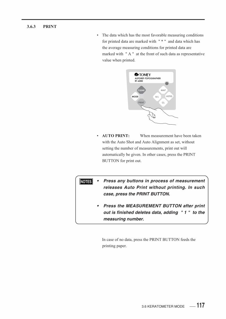
117
3.6.3 PRINT
• The data which has the most favorable measuring conditions
for printed data are marked with " * " and data which has
the average measuring conditions for printed data are
marked with " A " at the front of such data as representative
value when printed.
• AUTO PRINT: When measurement have been taken
with the Auto Shot and Auto Alignment as set, without
setting the number of measurements, print out will
automatically be given. In other cases, press the PRINT
BUTTON for print out.
• Press any buttons in process of measurementreleases Auto Print without printing. In suchcase, press the PRINT BUTTON.
• Press the MEASUREMENT BUTTON after printout is finished deletes data, adding " 1 " to themeasuring number.
In case of no data, press the PRINT BUTTON feeds the
printing paper.
AUTOREF-TOPOGRAPHERRT-6000
CLEAR
MODE
MAP
R/L ASTIG
CL
3.6 KERATOMETER MODE

118
<AN EXAMPLE OF PRINT>
3.6 KERATOMETER MODE
DATE: Sept/01/2002 0:00 NO. 1 NAME: <RIGHT> [KER] mm D AXIS K1 7.69 43.89 22 K2 7.57 44.58 112 AVG 7.63 44.23 CYL -0.69 22 [CL] BC P RA AXIS 7.65 -5.75 +0.38 39 [CL-DATA] CL NAME BC Dia MENICON Z 7.60 9.2 MENICON Sp-EX 7.75 8.8 <LEFT> [KER] mm D AXIS K1 7.84 43.05 176 K2 7.42 45.49 86 AVG 7.63 44.23 CYL -2.44 176 [CL] BC P RA AXIS 7.65 -4.50 +1.09 176 [CL-DATA] CL NAME BC Dia MENICON Z 7.60 9.2 MENICON Sp-EX 7.75 8.8 PD=66mm
*
*
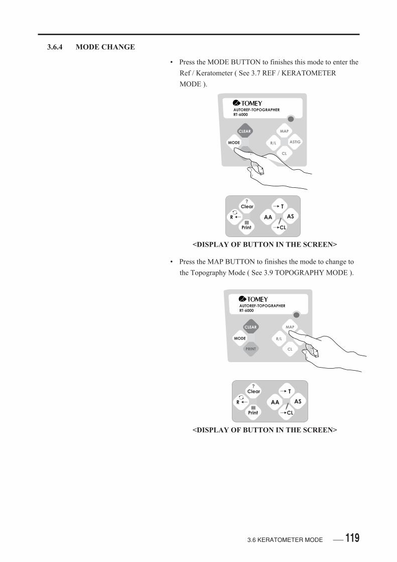
119
3.6.4 MODE CHANGE
• Press the MODE BUTTON to finishes this mode to enter the
Ref / Keratometer ( See 3.7 REF / KERATOMETER
MODE ).
• Press the MAP BUTTON to finishes the mode to change to
the Topography Mode ( See 3.9 TOPOGRAPHY MODE ).
AUTOREF-TOPOGRAPHERRT-6000
CLEAR
MODE
MAP
R/L ASTIG
CL
<DISPLAY OF BUTTON IN THE SCREEN>
3.6 KERATOMETER MODE
AUTOREF-TOPOGRAPHERRT-6000
CLEAR
MODE
MAP
R/L ASTIG
CL
<DISPLAY OF BUTTON IN THE SCREEN>
Clear
R
AA
T
AS
?
CL
Clear
R
AA
T
AS
?
CL

120
Press the MODE BUTTON to finishes the mode to change
to the Keratometer Mode ( See 3.5 REFRACTOMETER
MODE).
Press the MODE BUTTON long changes the screen to that
for the Refractometer Mode ( See 3.4 SETTING OF
OPERATING CONDITIONS ).
Press the CL BUTTON to finishes the mode to change to the
Contact Lens Mode ( See 3.5 REFRACTOMETER
MODE ).
3.6 KERATOMETER MODE

121
3.7 REF / KERATOMETER MODE
3.7.1 OPERATING SCREEN
• The Ref / Keratometer Mode is displayed in the following
screen structure.
• CORNEAL APEX DISTANCE:
When contact lens is selected at the upper right of the
screen, " VD = CL " is displayed. No display is given in
case of the framed lens like the spectales ( See 3.4.2
SETTING OF REF / KERATOMETER ).
• CLEAR BUTTON
Clear Data. ( See 3.7.2 MEASUREMENT ). Press this
button longer than a second to enter " Help " mode.
• MODE BUTTON
To enter Kerato Mode ( See 3.7.5 MODE CHANGE ). Press
this button longer than a second to displays the Mode
Change Screen ( See 3.4 SETTING OF OPERATING
CONDITIONS ).
• PRINT BUTTON
Prints measurement results.
<REF / KERATOMETER SCREEN>
VD=CL
PD
<CORNEAL APEX DISTANCE>
3.7 REF / KERATOMETER MODE
Ref-Keratometer VD=CL
LeftAuto Shot
Auto Alignment
1 / 9 / 02
0:00
1 s C A N PD
K1 K2 AV( ) ( ) N
Clear
K
AA
IOL / CAT
T
AS
?

122 3.7 REF / KERATOMETER MODE
• MAP BUTTON
Chnage the mode to the Topography Mode ( See 3.7.5
MODE CHANGE.
• R / L BUTTON
Setup Auto Alignment ( AA ).
• ASTIG BUTTON
Setup Auto shot ( AS ).
• CL BUTTON
The mode is changes to the Refractometer Measurement
Mode ( See 3.7.3 IOL AND CATARACT MODE ). Press
his button longer than a second to displays the Patient List
Setting Screen.
• PATIENTS LIST SETTING SCREEN
• CLEAR BUTTON
Clear the letters.
• MODE BUTTON
Change the letter type by alphabet and Numerical letters.
• PRINT BUTTON
The cursor is moved one letter to the right.
<SETTING OF PATIENT NAMES>
Ref-Keratometer VD=CL
LeftAuto Shot
Auto Alignment
1 / 9 / 02
0:00
1 s C A N PD
K1 K2 AV( ) ( ) N
Clear
K
AA
IOL / CAT
T
AS
?
Clear
MODE
ABCDEF
GHIJKL MNOPQR
STUVWXYZ
name: |
Exit
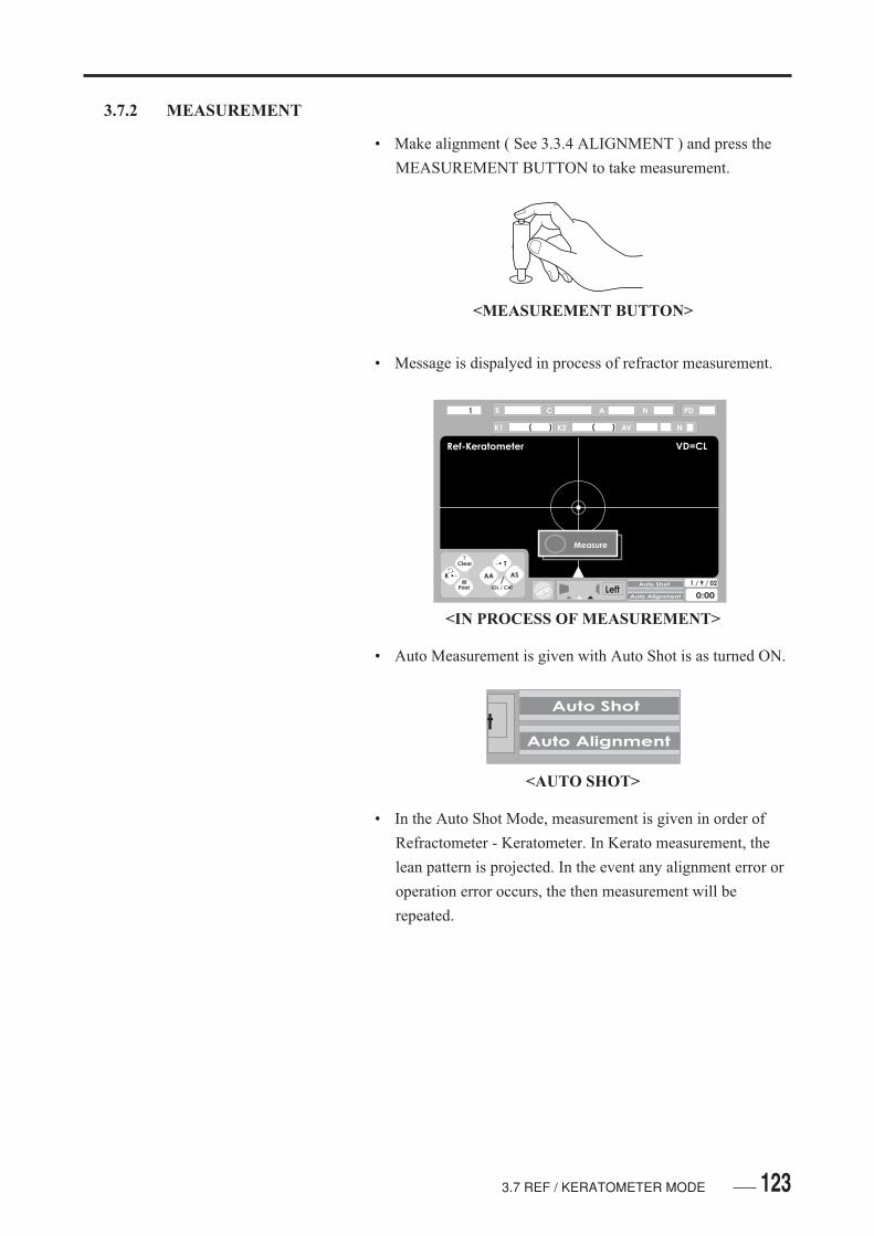
123
3.7.2 MEASUREMENT
• Make alignment ( See 3.3.4 ALIGNMENT ) and press the
MEASUREMENT BUTTON to take measurement.
• Message is dispalyed in process of refractor measurement.
• Auto Measurement is given with Auto Shot is as turned ON.
• In the Auto Shot Mode, measurement is given in order of
Refractometer - Keratometer. In Kerato measurement, the
lean pattern is projected. In the event any alignment error or
operation error occurs, the then measurement will be
repeated.
<MEASUREMENT BUTTON>
<IN PROCESS OF MEASUREMENT>
tAuto Shot
Auto Alignment
<AUTO SHOT>
3.7 REF / KERATOMETER MODE
Ref-Keratometer VD=CL
LeftAuto Shot
Auto Alignment
1 / 9 / 02
0:00
1 s C A N PD
Measure
K1 K2 AV( ) ( ) N
Clear
K
AA
IOL / CAT
T
AS
?

124
• In the following Refractor measurement data mayoften be at random.
In case the refractive power is not stable due toadjustment interference.
In case of frequent blinks.
In case the eyelid or eyelash interferes the pupil.
In case of exceeding turbid in the ocular media ofthe eye examined ( Catract, Eye Ground Hemor-rhage )
In case of the pupil diameter is less than 2.5mm.
• Measured data may be at random. In the Keratomeasurement.
In case of frequent blinks.
In case the eyelid or eyelash interferes the pupil.
In case of irregular astigmatism.
• When measurement is taken, the measuremrent data are
displayed on the upper part of the screen.
S:
Ref: Spherical Power [ D ] - When an error occurs, " Error "
is displayed.
C:
Ref: Astigmatism Power [ D ] - When an error occurs,
" Error " is displayed.
A:
Ref: Astigmatism axial angle.
<MEASURED DATA>
3.7 REF / KERATOMETER MODE
Ref-Keratometer VD=CL
1 s C A N PD
K1 K2 AV( ) ( )
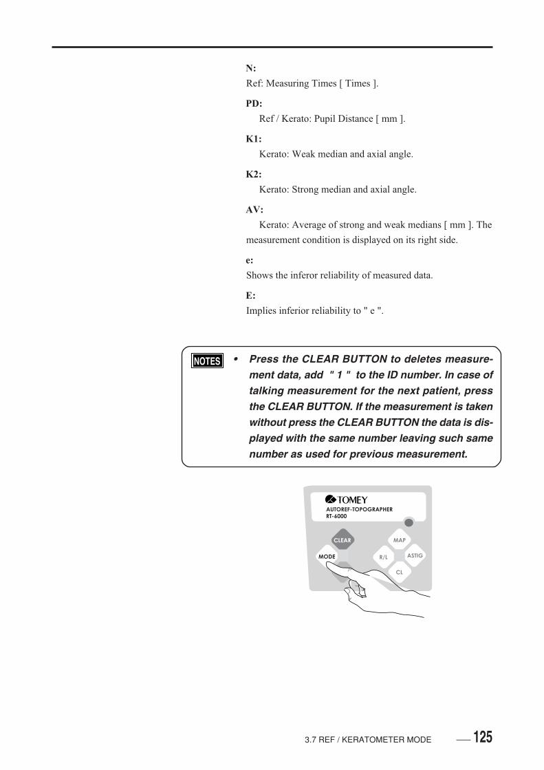
1253.7 REF / KERATOMETER MODE
N:
Ref: Measuring Times [ Times ].
PD:
Ref / Kerato: Pupil Distance [ mm ].
K1:
Kerato: Weak median and axial angle.
K2:
Kerato: Strong median and axial angle.
AV:
Kerato: Average of strong and weak medians [ mm ]. The
measurement condition is displayed on its right side.
e:
Shows the inferor reliability of measured data.
E:
Implies inferior reliability to " e ".
• Press the CLEAR BUTTON to deletes measure-ment data, add " 1 " to the ID number. In case oftalking measurement for the next patient, pressthe CLEAR BUTTON. If the measurement is takenwithout press the CLEAR BUTTON the data is dis-played with the same number leaving such samenumber as used for previous measurement.
AUTOREF-TOPOGRAPHERRT-6000
CLEAR
MODE
MAP
R/L ASTIG
CL
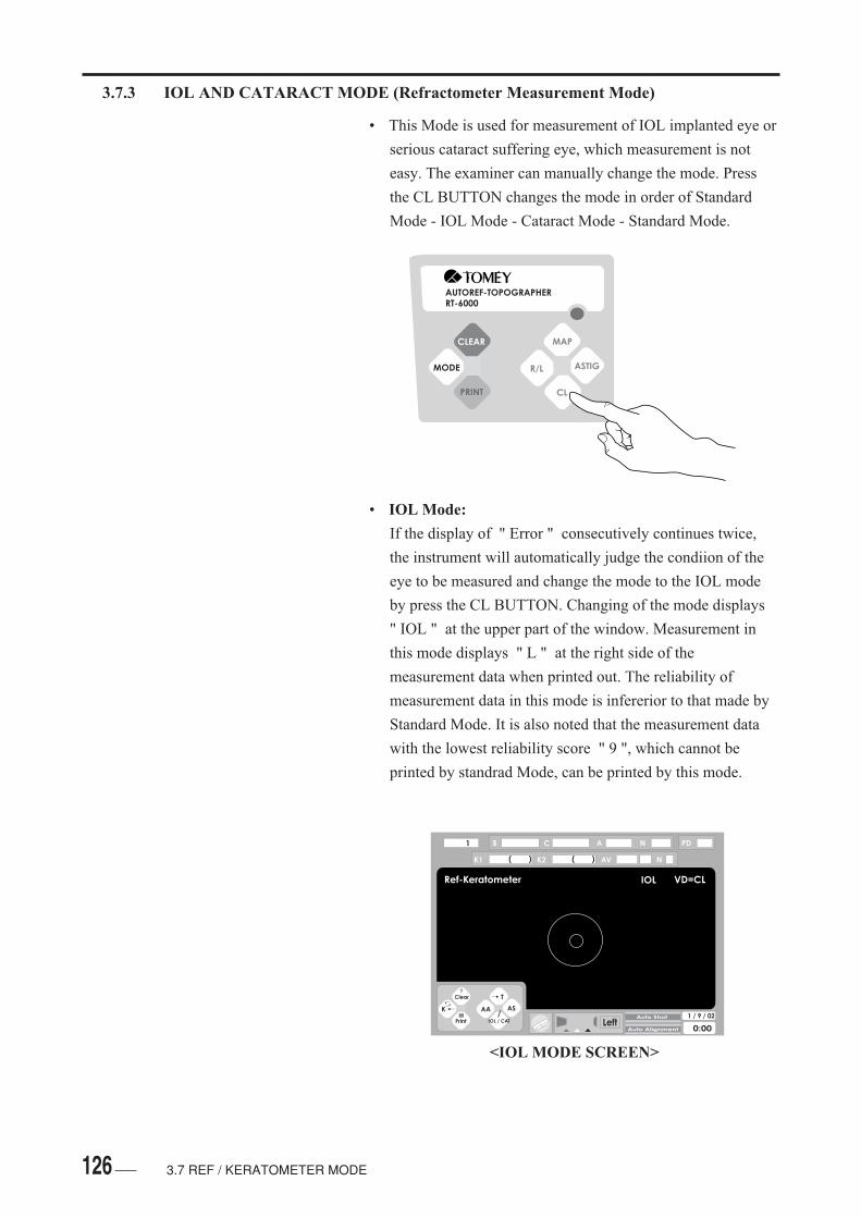
126
Ref-Keratometer VD=CL
LeftAuto Shot
Auto Alignment
1 / 9 / 02
0:00
1 s C A N PD
K1 K2 AV( ) ( ) N
Clear
K
AA
IOL / CAT
T
AS
?
IOL
<IOL MODE SCREEN>
3.7 REF / KERATOMETER MODE
3.7.3 IOL AND CATARACT MODE (Refractometer Measurement Mode)
• This Mode is used for measurement of IOL implanted eye or
serious cataract suffering eye, which measurement is not
easy. The examiner can manually change the mode. Press
the CL BUTTON changes the mode in order of Standard
Mode - IOL Mode - Cataract Mode - Standard Mode.
• IOL Mode:
If the display of " Error " consecutively continues twice,
the instrument will automatically judge the condiion of the
eye to be measured and change the mode to the IOL mode
by press the CL BUTTON. Changing of the mode displays
" IOL " at the upper part of the window. Measurement in
this mode displays " L " at the right side of the
measurement data when printed out. The reliability of
measurement data in this mode is infererior to that made by
Standard Mode. It is also noted that the measurement data
with the lowest reliability score " 9 ", which cannot be
printed by standrad Mode, can be printed by this mode.
AUTOREF-TOPOGRAPHERRT-6000
CLEAR
MODE
MAP
R/L ASTIG
CL

127
• Print out the data or press the CLEAR BUTTONby switch the Right / Left will automaticallychanges to the Standard Mode.
• This instrument does not, however, identify theeye with cataract or IOL implanted.
• CATARACT MODE:
When the display of " Error " consecutively continues, once
stop measurement and press the CL BUTTON to change the
mode to the Cataract Mode so that measurement can be
made again. Changing of the mode displays "CAT " at the
upper part of the window. Measurement made by this mode
displays " C " at the right side of measurement data. The
reliability of measurement data by this mode is inferior to
the Standard Mode. It is also noted that the measurement
data with the lowest reliability of " 9 ", which cannot be
printed, can be printed by this mode.
• Print out data or press the CLEAR BUTTON byswitch the Right / Left will automatically changesto the Standard Mode.
3.7 REF / KERATOMETER MODE
Ref-Keratometer VD=CL
LeftAuto Shot
Auto Alignment
1 / 9 / 02
0:00
1 s C A N PD
K1 K2 AV( ) ( ) N
Clear
K
AA
IOL / CAT
T
AS
?
CAT
<CATARACT MODE SCREEN>

128 3.7 REF / KERATOMETER MODE
3.7.4 PRINT
• Press the PRINT BUTTON to prints out measured data.
• Auto Print: When measurment have been with taken the
Auto Shot and the Auto Alignment as set, without setting the
number of measurements, print out will automatically be
given. In other cases, press the PRINT BUTTON for pint
out.
• Press either of the buttons releases the AutoPrint, by which print out will automatically re-cede. If thus occurs, press the PRINT BUTTON.
The data which has the most appropriate conditions is
printed out with " * " marked at its font as the
representative value.
Measurement values can be printed with a data reliability
coefficient of 0 to 9 on their right end. The smaller figue
( See 3.4.2 SETTING OF REF / KERATOMETER ), the
higher reliability ( See 1.3 GLOSSARY ). If no data is
taken, press the PRINT BUTTON feed the printer paper.
• When the MEASUREMENT BUTTON have beenmeasurement data will be deleted, add " 1 " to theID number.
AUTOREF-TOPOGRAPHERRT-6000
CLEAR
MODE
MAP
R/L ASTIG
CL

1293.7 REF / KERATOMETER MODE
• Before printing data, press the PRINT BUTTON longer than
a second to enough to confirm on it in the screen.
• The Data Display Window is displayed in the screen. To
close the window, press the PRINT BUTTON in a similar
manner above.
AUTOREF-TOPOGRAPHERRT-6000
CLEAR
MODE
MAP
R/L ASTIG
CL
<DISPLAY OF BUTTONS IN THE SCREEN>
<DATA DISPLAY WINDOW>
Ref-Keratometer VD=CL
LeftAuto Shot
Auto Alignment
1 / 9 / 02
0:00
1 s C A N PD
L +4.50 -5.25 37 0L +4.50 -5.25 37 0L* +4.50 -5.25 36 0
+ 4.75 - 5.25 36 3
K1 K2 AV( ) ( ) N8.32 41 7.70 131 8.01 1
Clear
K
AA
IOL / CAT
T
AS
?
Clear
K
AA
IOL / CAT
T
AS
?

130 3.7 REF / KERATOMETER MODE
DATE: Sept/01/ 2002 0:00 NO. 1 NAME: <RIGHT> [REF] VD=CL SPH CYL AXIS -6.00 -0.75 3 0 -6.00 -0.50 10 0 -6.00 -0.60 7 0 [KER] mm D AXIS K1 7.69 43.89 22 K2 7.57 44.58 112 AVG 7.63 44.23 CYL -0.69 22 [CL] BC P RA AXIS 7.65 -5.75 +0.38 39 [CL-DATA] CL NAME BC Dia MENICON Z 7.60 9.2 MENICON Sp-EX 7.75 8.8 <LEFT> [REF] VD=CL SPH CYL AXIS -3.75 -1.75 176 0 -4.50 -1.75 165 0 -4.00 -1.50 7 0 [KER] mm D AXIS K1 7.84 43.05 176 K2 7.42 45.49 86 AVG 7.63 44.23 CYL -2.44 176 [CL] BC P RA AXIS 7.65 -4.50 +1.09 176 [CL-DATA] CL NAME BC Dia MENICON Z 7.60 9.2 MENICON Sp-EX 7.75 8.8 PD=66mm
*
*
*
*
<AN EXAMPLE OF PRINT OUT>
Representative Refractive Power
Average Corneal Curvature
Residual Astigmatism Power

1313.7 REF / KERATOMETER MODE
3.7.5 MODE CHANGE
• Press the MAP BUTTON to finishes this mode to enter the
Topography Mode ( See 3.9 TOPOGRAPHY MODE ).
• The Topography Mode is closed and changed to the
Keratometer Mode ( See 3.6 KERATOMETER MODE).
Long and continuous press the MODE BUTTON changes
the mode to the Mode Change Screen.
AUTOREF-TOPOGRAPHERRT-6000
CLEAR
MODE
MAP
R/L ASTIG
CL
<DISPLAY OF BUTTONS IN THE SCREEN>
AUTOREF-TOPOGRAPHERRT-6000
CLEAR
MODE
MAP
R/L ASTIG
CL
<DISPLAY OF BUTTONS IN THE SCREEN>
Clear
K
AA
IOL / CAT
T
AS
?
Clear
K
AA
IOL / CAT
T
AS
?

132
• Press the MODE BUTTON for a few seconds, till the
MODE CHANGE SCREEN appears.
• Press the MAP BUTTON to finishing this mode and changes
to the Topography Mode ( See 3.9 TOPOGRAPHY
MODE ).
• Press the R / BUTTON to finishes this mode and changes to
the Keratometer Mode ( See 3.6 KERATOMETER
MODE ).
• Pressing the ASTIG BUTTON to finishes this mode and
displays the Setting Screen ( See 3.4 SETTING OF
OPERATING CONDITIONS ).
• Press the CL BUTTON to finishes this mode and changes
the Contact Lens Mode ( See 3.8 CONTACT LENS
MODE ).
• Press the MODE BUTTON to finishes the Mode Change
Screen and returns the Ref / Keratometer Mode.
<MODE CHANGE SCREEN>
AUTOREF-TOPOGRAPHER
RT-6000
CLEAR
MODE
MAP
R/L ASTIG
CL
3.7 REF / KERATOMETER MODE
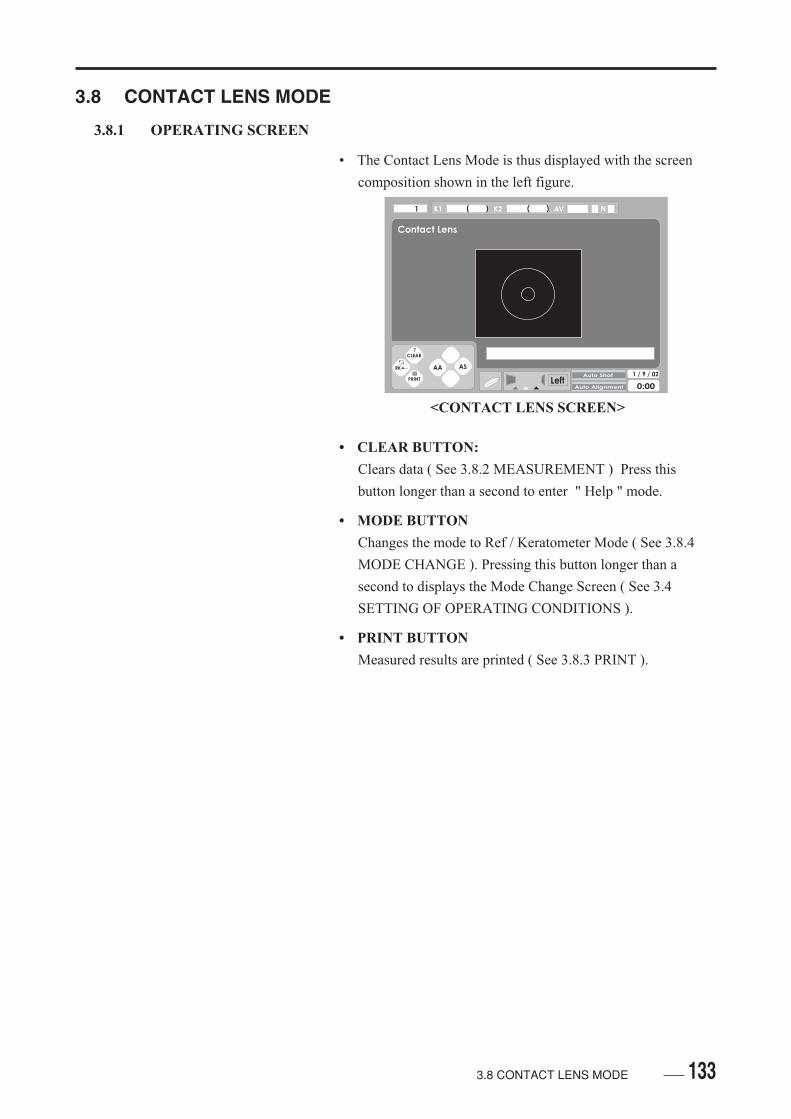
133
3.8 CONTACT LENS MODE
3.8.1 OPERATING SCREEN
• The Contact Lens Mode is thus displayed with the screen
composition shown in the left figure.
• CLEAR BUTTON:
Clears data ( See 3.8.2 MEASUREMENT ) Press this
button longer than a second to enter " Help " mode.
• MODE BUTTON
Changes the mode to Ref / Keratometer Mode ( See 3.8.4
MODE CHANGE ). Pressing this button longer than a
second to displays the Mode Change Screen ( See 3.4
SETTING OF OPERATING CONDITIONS ).
• PRINT BUTTON
Measured results are printed ( See 3.8.3 PRINT ).
<CONTACT LENS SCREEN>
3.8 CONTACT LENS MODE
Contact Lens
LeftAuto Shot
Auto Alignment
1 / 9 / 02
0:00
1 K1 K2 AV( ) ( ) N
CLEAR
RK
AA AS
?
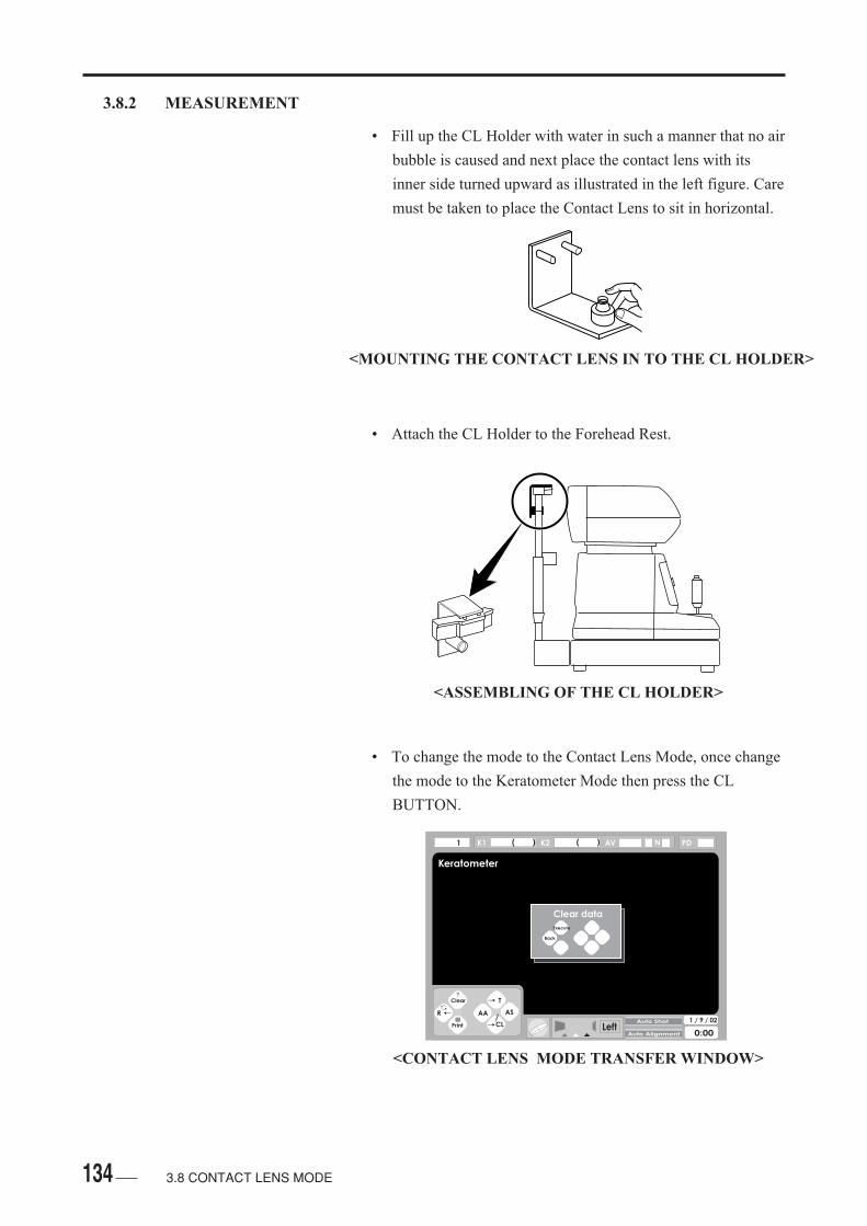
134
3.8.2 MEASUREMENT
• Fill up the CL Holder with water in such a manner that no air
bubble is caused and next place the contact lens with its
inner side turned upward as illustrated in the left figure. Care
must be taken to place the Contact Lens to sit in horizontal.
• Attach the CL Holder to the Forehead Rest.
• To change the mode to the Contact Lens Mode, once change
the mode to the Keratometer Mode then press the CL
BUTTON.
<MOUNTING THE CONTACT LENS IN TO THE CL HOLDER>
<ASSEMBLING OF THE CL HOLDER>
3.8 CONTACT LENS MODE
<CONTACT LENS MODE TRANSFER WINDOW>
Keratometer
LeftAuto Shot
Auto Alignment
1 / 9 / 02
0:00
1 PD
Clear
R
AA
CL
T
AS
?
K1 K2 AV( ) ( ) N
Clear data
Execute
Back
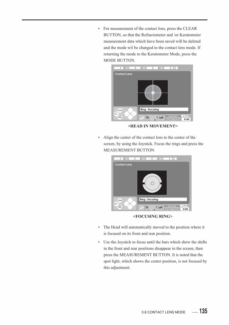
135
• For measurement of the contact lens, press the CLEAR
BUTTON, so that the Refractometer and /or Keratometer
measurement data which have been saved will be deleted
and the mode wil be changed to the contact lens mode. If
returning the mode to the Keratometer Mode, press the
MODE BUTTON.
• Align the center of the contact lens to the center of the
screen, by using the Joystick. Focus the rings and press the
MEASUREMENT BUTTON.
• The Head will automatically moved to the position where it
is focused on its front and rear position.
• Use the Joystick to focus until the bars which show the shifts
in the front and rear positions disappear in the screen, then
press the MEASUREMENT BUTTON. It is noted that the
spot light, which shows the center position, is not focused by
this adjustment.
3.8 CONTACT LENS MODE
<HEAD IN MOVEMENT>
<FOCUSING RING>
Contact Lens
LeftAuto Shot
Auto Alignment
1 / 9 / 02
0:00
1 K1 K2 AV( ) ( ) N
CLEAR
RK
? Ring : Focusing
Contact Lens
LeftAuto Shot
Auto Alignment
1 / 9 / 02
0:00
1 K1 K2 AV( ) ( ) N
CLEAR
RK
? Ring : Focusing

136
• The Head is automatically moved to the measuring position,
next auto-alignment is made for up/down and right/left, and
then the rings illuminate to start measurement.
• Do not move the Joystick while the Head is inmovement, which may otherwise disorder mea-surement.
• Care should also be taken not to cause the con-tact lens with strain, damage, or stain, which maygive correct measurement.
• After measurement is finished and related measurement data
will be displayed in the screen.
3.8 CONTACT LENS MODE
<ALIGNMENT OF FRONT/REAR POSITION>
<MEASUREMENT>
Contact Lens
1 K1 K2 AV( ) ( ) N
<DATA DISPLAY>
Contact Lens
LeftAuto Shot
Auto Alignment
1 / 9 / 02
0:00
1 K1 K2 AV( ) ( ) N
CLEAR
RK
? Z: Alignment
Contact Lens
LeftAuto Shot
Auto Alignment
1 / 9 / 02
0:00
1 K1 K2 AV( ) ( ) N
CLEAR
RK
?

1373.8 CONTACT LENS MODE
K1:
Weak meridian and axial angle.
K2:
Strong meridian and axial angle.
AV:
Mean value [ mm ] of strong and weak meridians.
Measurement conditions is displayed on its end .
e:
Indicates inferior reliability of measurement.
E:
More inferior reliability than " e ".
• If the same contact lens as previously measured is re-
measured, re-focus the rings, since the instrument condition
has been retuned to its condition used for the measurement
position, then press the MEASUREMENT BUTTON.
• When the next contact lens i measured after above, press the
CLEAR BUTTON to delete previously measured data and to
the measurement number will be added. If measuring the
next contact lenses without printing, press the CLEAR
BUTTON.
AUTOREF-TOPOGRAPHERRT-6000
CLEAR
MODE
MAP
R/L ASTIG
CL
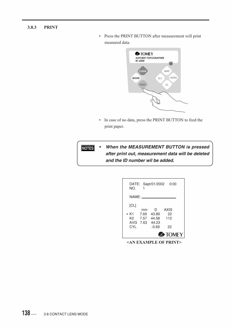
138
3.8.3 PRINT
• Press the PRINT BUTTON after measurement will print
measured data.
• In case of no data, press the PRINT BUTTON to feed the
print paper.
• When the MEASUREMENT BUTTON is pressedafter print out, measurement data will be deletedand the ID number wil be added.
AUTOREF-TOPOGRAPHERRT-6000
CLEAR
MODE
MAP
R/L ASTIG
CL
DATE: Sept/01/2002 0:00 NO. 1 NAME: [CL] mm D AXIS K1 7.69 43.89 22 K2 7.57 44.58 112 AVG 7.63 44.23 CYL -0.69 22
*
<AN EXAMPLE OF PRINT>
3.8 CONTACT LENS MODE

139
3.8.4 MODE CHANGE
• Press the MODE BUTTON to finishes this mode to enter the
Ref / Keratometer Mode. ( See 3.7 REF / KERATOMETER
MODE ).
• The screen used to finished the Contact Lens Mode is
displayed. Press the CLEAR BUTTON to clears data and
finishes the Contact Lens Mode, which cannot be made by
MODE BUTTON.
• Press the CLEAR BUTTON to clears measure-ment data and the ID number wi l l beadded.adding.
AUTOREF-TOPOGRAPHERRT-6000
CLEAR
MODE
MAP
R/L ASTIG
CL
<DISPLAY OF BUTTON IN THE SCREEN>
Clear
RK
AA AS
?
3.8 CONTACT LENS MODE
<REF / KERATOMETER MODE TRANSFER WINDOW>
Contact Lens
LeftAuto Shot
Auto Alignment
1 / 9 / 02
0:00
1 K1 K2 AV( ) ( ) N
CLEAR
RK
?
Clear data
Execute
Back

140
( This page is left intentionally in blank )
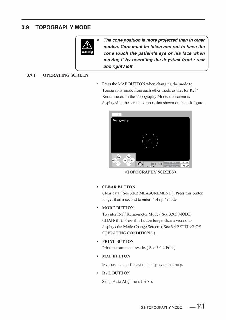
141
3.9 TOPOGRAPHY MODE
• The cone position is more projected than in othermodes. Care must be taken and not to have thecone touch the patient's eye or his face whenmoving it by operating the Joystick front / rearand right / left.
3.9.1 OPERATING SCREEN
• Press the MAP BUTTON when changing the mode to
Topography mode from such other mode as that for Ref /
Keratometer. In the Topography Mode, the screen is
displayed in the screen composition shown on the left figure.
• CLEAR BUTTON
Clear data ( See 3.9.2 MEASUREMENT ). Press this button
longer than a second to enter " Help " mode.
• MODE BUTTON
To enter Ref / Keratometer Mode ( See 3.9.5 MODE
CHANGE ). Press this button longer than a second to
displays the Mode Change Screen. ( See 3.4 SETTING OF
OPERATING CONDITIONS ).
• PRINT BUTTON
Print measurement results ( See 3.9.4 Print).
• MAP BUTTON
Measured data, if there is, is displayed in a map.
• R / L BUTTON
Setup Auto Alignment ( AA ).
<TOPOGRAPHY SCREEN>
3.9 TOPOGRAPHY MODE
Topography
LeftAuto Alignment
1 / 9 / 02
0:00
1
Clear
RK
Cone
AA
CL
AS
?MAP
Auto Shot
142 3.9 TOPOGRAPHY MODE
• ASTIG BUTTON
Setup Auto Shot ( AS ).
• CL BUTTON
The mode is changes to the Contact Mode ( See 3.8
CONTACT LENS MODE ). Press this button longer than a
second to displays the Patient Name Setting Screen ( See
3.4.1 SETTING OF THE SCREEN ). Press the CL
BUTTON displays the screen to change the mode to the
Contact Lens Mode. Pressing of the CLEAR BUTTON
clears data to changes the mode to the Contact Lens Mode.
No mode change is made by simply press the MODE
BUTTON.
• Press the CLEAR BUTTON to clears measureddata and the ID number will be added.

143
3.9.2 MEASUREMENT
• Move the cone to the side of the patient. If Auto Cone
Measurement of " 3.4.3 SETTING OF TOPOGRAPHY " is
turned for " ENABLED " and by pulling the Head Rest to
the patient side all its way, the cone will automatically be
moved to the most projected position.
• In case of " DISABLED " turned, the cone is automatically
moved to the most projected position, by pulling the Hear
Rest all its way and next press the PRINT BUTTON.
• The cone position is displayed in the lower center of the
screen. In the Topography Mode, measurement can be given
in either of the position which is closest ( red ) to or a little
away ( yellow ) from the cornea.
• Make alignment ( See 3.3.4 ALIGNMENT ). If the cone
touches the patient, press the PRINT BUTTON to retract the
cone to the yellow colored position in the screen. The
corneal range to be measured is narrowed.
AUTOREF-TOPOGRAPHERRT-6000
CLEAR
MODE
MAP
R/L ASTIG
CL
<DISPLAY OF BUTTON IN THE SCREEN>
Left
<CONE POSITION>
Clear
RK
Cone
AA
Map
CL
AS
?
3.9 TOPOGRAPHY MODE
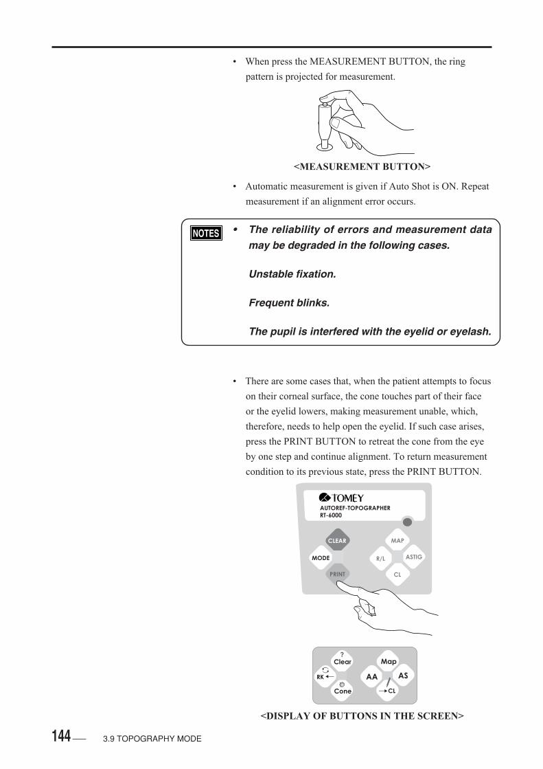
144
• When press the MEASUREMENT BUTTON, the ring
pattern is projected for measurement.
• Automatic measurement is given if Auto Shot is ON. Repeat
measurement if an alignment error occurs.
• The reliability of errors and measurement datamay be degraded in the following cases.
Unstable fixation.
Frequent blinks.
The pupil is interfered with the eyelid or eyelash.
• There are some cases that, when the patient attempts to focus
on their corneal surface, the cone touches part of their face
or the eyelid lowers, making measurement unable, which,
therefore, needs to help open the eyelid. If such case arises,
press the PRINT BUTTON to retreat the cone from the eye
by one step and continue alignment. To return measurement
condition to its previous state, press the PRINT BUTTON.
3.9 TOPOGRAPHY MODE
AUTOREF-TOPOGRAPHERRT-6000
CLEAR
MODE
MAP
R/L ASTIG
CL
<DISPLAY OF BUTTONS IN THE SCREEN>
<MEASUREMENT BUTTON>
Clear
RK
Cone
AA
Map
CL
AS
?

145
• The cone is automatically lowered to its ordinaryposition ( colored green ) after the map is dis-played. Care must be taken when operate theJoystick to the front / rear and / or Right / Left,which may cause the cone to touch the patient'seye or face.
• Do not give button operation while one move-ment is displayed.
• should the cone be lowered, the measuring posi-tion will be narrowed.
• Press the MAP BUTTON or the PRINT BUTTON longer
than a second, so the map, which has been analyzed from the
Measurement Screen immediately before pressing the button
will be displayed.
Topography
LeftAuto Alignment
1 / 9 / 02
0:00
1
Clear
RK
Cone
AA
CL
AS
?MAP
Auto Shot
Cone is moving
<CONE MOVEMENT IN PROCESS>
3.9 TOPOGRAPHY MODE
AUTOREF-TOPOGRAPHERRT-6000
CLEAR
MODE
MAP
R/L ASTIG
CL
<DISPLAY OF BUTTONS IN THE SCREEN>
Clear
RK
Cone
AA
Map
CL
AS
?
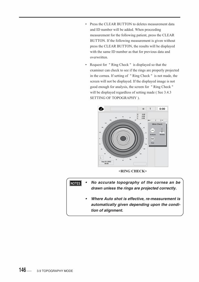
146
<RING CHECK>
• Press the CLEAR BUTTON to deletes measurement data
and ID number will be added. When proceeding
measurement for the following patient, press the CLEAR
BUTTON. If the following measurement is given without
press the CLEAR BUTTON, the results will be displayed
with the same ID number as that for previous data and
overwritten.
• Request for " Ring Check " is displayed so that the
examiner can check to see if the rings are properly projected
in the cornea. If setting of " Ring Check " is not made, the
screen will not be displayed. If the displayed image is not
good enough for analysis, the screen for " Ring Check "
will be displayed regardless of setting made ( See 3.4.3
SETTING OF TOPOGRAPHY ).
• No accurate topography of the cornea an bedrawn unless the rings are projected correctly.
• Where Auto shot is effective, re-measurement isautomatically given depending upon the condi-tion of alignment.
3.9 TOPOGRAPHY MODE
....
..
..
..
.
.
.
.
..
..
..
..
. . . .. .
..
..
..
..
.
.
..
..
..
..
..90
105
120
135
150
165
0
15
30
45
60
7590
105
120
135
150
165
0
15
30
45
60
75
0:00ID 1
X: 0.00Y: 0.00Z: 0.00
LSep/01/2002 00:00
TK1
TK2
Ave
X
XMires Check
Analysis Retake
MAP
( )

147
• Analysis:
Press the MAP BUTTON displays the map from the Ring
Check Screen.
• Re-Measurement:
Press the MEASUREMENT BUTTON starts re-
measurement. In case of a wrong Ring Check, fluctuating
patient's movement, or unclear rings due to undue patient
movement or excessive tears re-measurement should be
given.
• Print:
Pressing the PRINT BUTTON to prints measurement data
into the external digital printer connected to the instrument.
AUTOREF-TOPOGRAPHERRT-6000
CLEAR
MODE
MAP
R/L ASTIG
CL
3.9 TOPOGRAPHY MODE

148
3.9.3 SINGLE MAP SCREEN
• The Single Map is displayed.
• CLINIC NAME:
The clinic name is displayed ( See 3.4.3 SETTING OF
TOPOGRAPHY ).
• CENTER OFFSETS:
The offsets from the center of the rings are displayed.
• x:
Offsets from center of the ring and the measuring center, in
the horizontal direction [ mm ].
• y:
Offsets from center of the ring and the measuring center, in
the vertical direction [ mm ].
• z:
Offset from center of the ring and the measuring center, in
the front and rear direction [ mm ].
Contact LensScaleMap TypeMeasuring Time
<SINGLE MAP>
3.9 TOPOGRAPHY MODE
....
..
..
..
.
.
.
.
..
..
..
..
. . . .. .
..
..
..
..
.
.
..
..
..
..
..90
105
120
135
150
165
0
15
30
45
60
7590
105
120
135
150
165
0
15
30
45
60
75
0:00ID 1
X:Y:Z:
K1
K2
Ave
X
X
0.14- 0.03- 0.01
40.74 ( 8.28 )
43.87 ( 7.69 )
42.25 ( 7.99 )
11
101
- 3.00Cyl
RSep/01/2002 00:00 Absolute
BC
BC
BC
BC
BC
BC
BC
D
D
D
D
D
D
D
MENICON Z
MENICON EX
MENICON EX
7.70 9.2
7.75 9.2
7.75 9.6
101.5
96.5
91.5
86.5
81.5
76.571.566.561.556.550.549.047.546.044.543.041.540.038.537.035.529.024.019.014.0
9.0diopter
ECC - 0.37
Center Offsets
Clinic Name
ClockMeasured Data

149
• The black colored display implies the misalignment within
the allowance range, which has no influence on the display
image.
• The yellow colored display implies the misalignment around
the allowance range, which may possibility have influence
on the display image.
• The red colored display implies the misalignment exclusive
of the allowance, which may have undue influence on the
display image and requires re-measurement.
• The ring pattern made in measurement is pro-jected after alignment is completed, for the rea-son of which a large extent of misalignment maypossibily be caused when the movement of thepatient is large. Such excesive misalignment can-not be revise, possibily causing a colored mapdifferent from the actual condition.
• The above topography shows an example Color Map for an
eye having no astigmatism, for which measurement was
taken with offsets and, therefore, the colors used for the Map
are symmetrically different between the right and left sides
from the center of the average value.
3.9 TOPOGRAPHY MODE
<MISALIGNMENT>
....
..
..
..
.
.
.
.
..
..
..
..
. . . .. .
..
..
..
..
.
.
..
..
..
..
..90
105
120
135
150
165
0
15
30
45
60
7590
105
120
135
150
165
0
15
30
45
60
75
0:00ID 1
X:Y:Z:
K1
K2
Ave
X
X
- 0.15 0.06- 0.01
33.82 ( 9.98 ) 77
167
0.00Cyl
LSep/01/00 00:00 Absolute
BC
BC
BC
BC
BC
BC
BC
D
D
D
D
D
D
D
MENICON Z
MENICON EX
MENICON EX
7.70 9.2
7.75 9.2
7.75 9.6
101.5
96.5
91.5
86.5
81.5
76.571.566.561.556.550.549.047.546.044.543.041.540.038.537.035.529.024.019.014.0
9.0diopter
33.82 ( 9.98 )
33.82 ( 9.98 )
- 0.37ECC
Misalignment
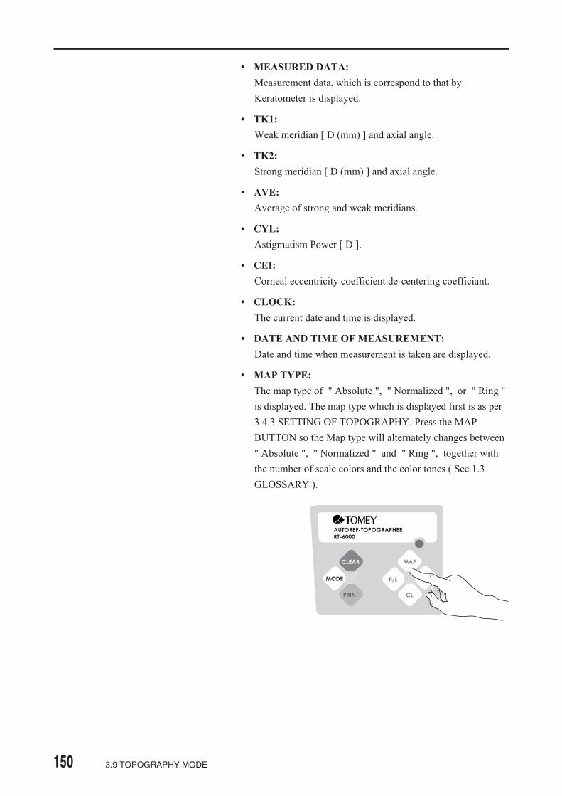
150 3.9 TOPOGRAPHY MODE
• MEASURED DATA:
Measurement data, which is correspond to that by
Keratometer is displayed.
• TK1:
Weak meridian [ D (mm) ] and axial angle.
• TK2:
Strong meridian [ D (mm) ] and axial angle.
• AVE:
Average of strong and weak meridians.
• CYL:
Astigmatism Power [ D ].
• CEI:
Corneal eccentricity coefficient de-centering coefficiant.
• CLOCK:
The current date and time is displayed.
• DATE AND TIME OF MEASUREMENT:
Date and time when measurement is taken are displayed.
• MAP TYPE:
The map type of " Absolute ", " Normalized ", or " Ring "
is displayed. The map type which is displayed first is as per
3.4.3 SETTING OF TOPOGRAPHY. Press the MAP
BUTTON so the Map type will alternately changes between
" Absolute ", " Normalized " and " Ring ", together with
the number of scale colors and the color tones ( See 1.3
GLOSSARY ).
AUTOREF-TOPOGRAPHERRT-6000
CLEAR
MODE
MAP
R/L ASTIG
CL

151
• SCALE:
The color scale and units ( [D] or [mm] ) are displayed. The
units to be displayed are as mentioned in 3.4.3 SETTING
OF TOPOGRAPHY. The Absolute Scale is graduated in 26
parts for 9.0 to 100.0D, while the Normalized Scale is
graduated i parts from the average of strong and weak
meridians.
• CONTACT LENS:
The list of contact lenses is displayed. Brand names,
diameters ( D ), and base curves ( BC ) are respectively
displayed. The details and order of brand names are displaed
on the description given in 3.4.5 SETTING OF CONTACT
LENS LIST. To display the next brand name, pres the CL
BUTTON. Each press of the button displays 8 brands in
order. After the blank showing no brand name list is
displayed, te consecutive display will repeat showing the
first brand name.
3.9 TOPOGRAPHY MODE
101.5
96.5
91.5
86.5
81.5
76.571.566.561.556.550.549.047.546.044.543.041.540.038.537.035.529.024.019.014.0
9.0diopter
45.9
45.5
45.1
44.7
44.3
43.9
43.5
43.1
42.7
42.3
41.9
diopter
<SCALE ( ABSOLUTE / NORMALIZED )>
<DISPLAY OF CONTACT LENS FITTING>
....
..
..
..
.
.
.
.
..
..
..
..
. . . .. .
..
..
..
..
.
.
..
..
..
..
..90
105
120
135
150
165
0
15
30
45
60
7590
105
120
135
150
165
0
15
30
45
60
75
0:00ID 1
X:Y:Z:
K1
K2
Ave
X
X
0.14- 0.03- 0.01
40.74 ( 8.28 )
43.87 ( 7.69 )
42.25 ( 7.99 )
11
101
- 3.00Cyl
RSep/01/2002 00:00 Absolute
BC
BC
BC
BC
BC
BC
BC
D
D
D
D
D
D
D
MENICON Z
MENICON EX
MENICON EX
7.70 9.2
7.75 9.2
7.75 9.6
101.5
96.5
91.5
86.5
81.5
76.571.566.561.556.550.549.047.546.044.543.041.540.038.537.035.529.024.019.014.0
9.0diopter
ECC - 0.37
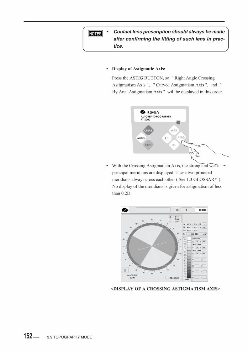
152
AUTOREF-TOPOGRAPHERRT-6000
CLEAR
MODE
MAP
R/L ASTIG
CL
<DISPLAY OF A CROSSING ASTIGMATISM AXIS>
• Contact lens prescription should always be madeafter confirming the fitting of such lens in prac-tice.
• Display of Astigmatic Axis:
Press the ASTIG BUTTON, so " Right Angle Crossing
Astigmatism Axis ", " Curved Astigmatism Axis ", and "
By Area Astigmatism Axis " will be displayed in this order.
• With the Crossing Astigmatism Axis, the strong and weak
principal meridians are displayed. These two principal
meridians always cross each other ( See 1.3 GLOSSARY ).
No display of the meridians is given for astigmatism of less
than 0.2D.
3.9 TOPOGRAPHY MODE
....
..
..
..
.
.
.
.
..
..
..
..
. . . .. .
..
..
..
..
.
.
..
..
..
..
..90
105
120
135
150
165
0
15
30
45
60
7590
105
120
135
150
165
0
15
30
45
60
75
0:00ID 1
X:Y:Z:
K1
K2
Ave
X
X
0.14- 0.03- 0.01
40.74 ( 8.28 )
43.87 ( 7.69 )
42.25 ( 7.99 )
11
101
- 3.00Cyl
RSep/01/2002 00:00 Absolute
BC
BC
BC
BC
BC
BC
BC
D
D
D
D
D
D
D
MENICON Z
MENICON EX
MENICON EX
7.70 9.2
7.75 9.2
7.75 9.6
101.5
96.5
91.5
86.5
81.5
76.571.566.561.556.550.549.047.546.044.543.041.540.038.537.035.529.024.019.014.0
9.0diopter
- 0.37ECC

153
• With Curved Astigmatism AXIS, the line connected between
the highest refractive values and that connected between the
lowest refractive values are displayed ( See 1.3
GLOSSARY ). No display is given if the astigmatism is less
than 10D.
• With By-Area Astigmatism Axis, the strong and weak
meridians in the areasof 3mm, 5mm, and 7mm ( R=7.7mm)
from the center and the refractive value ( mm or D ) and
angle on the weak meridian are displayed ( See 1.3
GLOSSARY ). No display is given if the Astigmatism is less
than 1.0D.
<DISPLAY OF CURVED ASTIGMATISM AXIS>
<DISPLAY OF BY-AREA ASTIGMATISM AXIS>
....
..
..
..
.
.
.
.
..
..
..
..
. . . .. .
..
..
..
..
.
.
..
..
..
..
..90
105
120
135
150
165
0
15
30
45
60
7590
105
120
135
150
165
0
15
30
45
60
75
0:00ID 1
X:Y:Z:
K1
K2
Ave
X
X
0.14- 0.03- 0.01
40.74 ( 8.28 )
43.87 ( 7.69 )
42.25 ( 7.99 )
11
101
- 3.00Cyl
RSep/01/2002 00:00 Absolute
101.5
96.5
91.5
86.5
81.5
76.571.566.561.556.550.549.047.546.044.543.041.540.038.537.035.529.024.019.014.0
9.0diopter
- 0.37ECC
3
5
7
mm Diopter Axis
8.31
7.71
8.30
7.73
40.60
43.85
40.65
43.68
7
97
187
277
8.31
7.71
8.28
7.71
40.63
43.80
40.75
43.77
11
101
191
281
8.33
7.70
8.28
7.72
40.50
43.81
40.78
43.71
11
101
191
281
3.9 TOPOGRAPHY MODE
....
..
..
..
.
.
.
.
..
..
..
..
. . . .. .
..
..
..
..
.
.
..
..
..
..
..90
105
120
135
150
165
0
15
30
45
60
7590
105
120
135
150
165
0
15
30
45
60
75
0:00ID 1
X:Y:Z:
K1
K2
Ave
X
X
0.14- 0.03- 0.01
40.74 ( 8.28 )
43.87 ( 7.69 )
42.25 ( 7.99 )
11
101
- 3.00Cyl
RSep/01/2002 00:00 Absolute
BC
BC
BC
BC
BC
BC
BC
D
D
D
D
D
D
D
MENICON Z
MENICON EX
MENICON EX
7.70 9.2
7.75 9.2
7.75 9.6
101.5
96.5
91.5
86.5
81.5
76.571.566.561.556.550.549.047.546.044.543.041.540.038.537.035.529.024.019.014.0
9.0diopter
- 0.37ECC
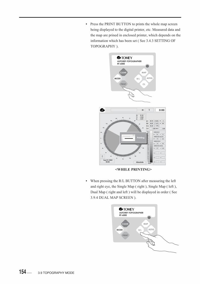
154
• Press the PRINT BUTTON to prints the whole map screen
being displayed to the digital printer, etc. Measured data and
the map are prined in enclosed printer, which depends on the
information which has been set ( See 3.4.3 SETTING OF
TOPOGRAPHY ).
• When pressing the R/L BUTTON after measuring the left
and right eye, the Single Map ( right ), Single Map ( left ),
Dual Map ( right and left ) will be displayed in order ( See
3.9.4 DUAL MAP SCREEN ).
AUTOREF-TOPOGRAPHERRT-6000
CLEAR
MODE
MAP
R/L ASTIG
CL
<WHILE PRINTING>
AUTOREF-TOPOGRAPHERRT-6000
CLEAR
MODE
MAP
R/L ASTIG
CL
3.9 TOPOGRAPHY MODE
....
..
..
..
.
.
.
.
..
..
..
..
. . . .. .
..
..
..
..
.
.
..
..
..
..
..90
105
120
135
150
165
0
15
30
45
60
7590
105
120
135
150
165
0
15
30
45
60
75
0:00ID 1
X:Y:Z:
K1
K2
Ave
X
X
0.14- 0.03- 0.01
40.74 ( 8.28 )
43.87 ( 7.69 )
42.25 ( 7.99 )
11
101
- 3.00Cyl
RSep/01/2002 00:00 Absolute
BC
BC
BC
BC
BC
BC
BC
D
D
D
D
D
D
D
MENICON Z
MENICON Super EX
MENICON EX
MENICON Soft MA
8.6 9.6
9.0 8.8
9.0 8.8
8.7 13.0
101.5
96.5
91.5
86.5
81.5
76.571.566.561.556.550.549.047.546.044.543.041.540.038.537.035.529.024.019.014.0
9.0diopter
Printing
- 3.00ECC

155
• Press the CLEAR BUTTON to deletes the map data and the
ID number will be added, then changes the screen mode to
the Measuring Screen. For the next patient, press the
CLEAR BUTTON. If processing to the next measurement
without pressing the CLEAR BUTTON, the same ID
number above is displayed, overwriting the data.
• Press the MEASUREMENT BUTTON to retains measured
map data, followed by changing the screen to the
Measurement Screen. In case of measuring the same eye or
the opposite eye, press the MEASUREMENT BUTTON.
• If the movement of the eye being examined islarge when taking measurement, the center mis-alignment may be become large. If this occurs,such misalignment may not be corrected to sub-sequently show a colored map different from thatfor the actual corneal shape. Be sure to check theamount of misalignment shown at the upper rightof the map. In case any of the figures is displayedin red or yellow color, take another measurement.
AUTOREF-TOPOGRAPHERRT-6000
CLEAR
MODE
MAP
R/L ASTIG
CL
<MEASUREMENT BUTTON>
3.9 TOPOGRAPHY MODE
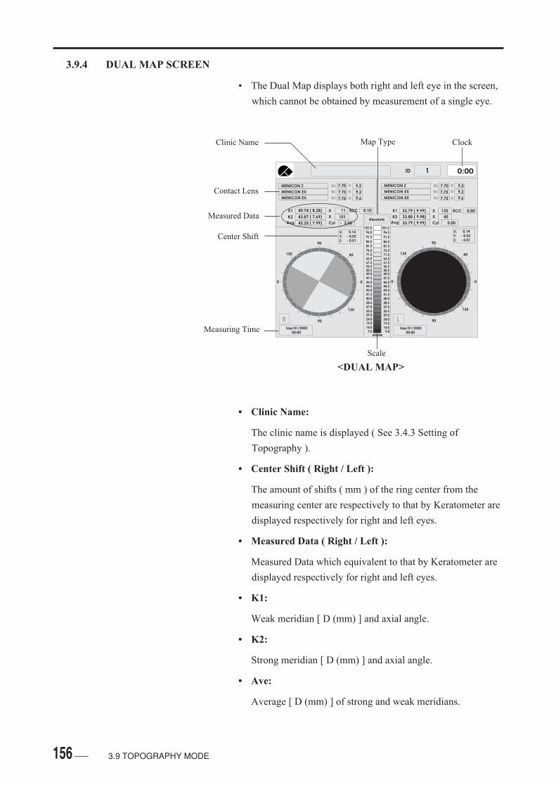
156
3.9.4 DUAL MAP SCREEN
• The Dual Map displays both right and left eye in the screen,
which cannot be obtained by measurement of a single eye.
• Clinic Name:
The clinic name is displayed ( See 3.4.3 Setting of
Topography ).
• Center Shift ( Right / Left ):
The amount of shifts ( mm ) of the ring center from the
measuring center are respectively to that by Keratometer are
displayed respectively for right and left eyes.
• Measured Data ( Right / Left ):
Measured Data which equivalent to that by Keratometer are
displayed respectively for right and left eyes.
• K1:
Weak meridian [ D (mm) ] and axial angle.
• K2:
Strong meridian [ D (mm) ] and axial angle.
• Ave:
Average [ D (mm) ] of strong and weak meridians.
<DUAL MAP>
3.9 TOPOGRAPHY MODE
0:00ID 1
X
X
Cyl
MENICON Z
MENICON EX
MENICON EX
BC
BC
BC
D
D
D
7.70 9.2
7.75
7.75
9.2
9.6
BC
BC
BC
D
D
D
MENICON Z
MENICON EX
MENICON EX
7.70 9.2
7.75 9.2
9.67.75
33.79 ( 9.99)
33.80 ( 9.98)
33.79 ( 9.99)
135
45
0.00
40.74 ( 8.28)
43.87 ( 7.69)
42.25 ( 7.99)
X
X
Cyl
11
101
- 3.00
K1
K2
Avg
K1
K2
Avg101.5
96.5
91.5
86.581.576.571.566.561.556.550.549.047.546.044.543.041.540.038.537.035.529.024.019.014.0
9.0diopter
101.596.5
91.5
86.581.576.571.566.561.556.550.549.047.546.044.543.041.540.038.537.035.529.024.019.014.0
9.0
Absolute
0 0
90
135
90
135
45
X:Y:Z:
0.14- 0.03- 0.01
RSep/01/2002 00:00
0 0
90
135
90
135
45
X:Y:Z:
0.14- 0.03- 0.01
LSep/01/2002 00:00
ECC 0.10 ECC 0.00
Clinic Name
Contact Lens
Measured Data
Center Shift
Measuring Time
Scale
Map Type Clock
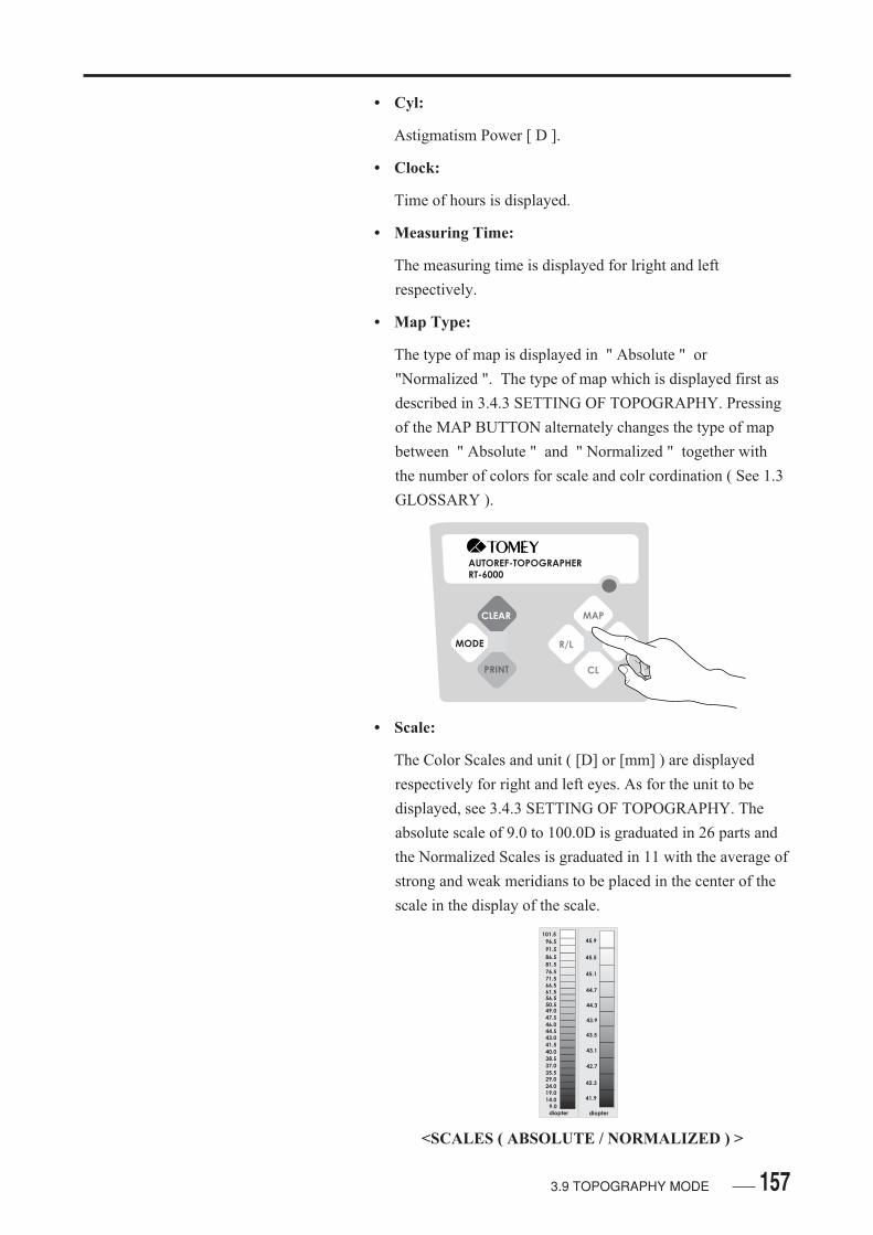
157
• Cyl:
Astigmatism Power [ D ].
• Clock:
Time of hours is displayed.
• Measuring Time:
The measuring time is displayed for lright and left
respectively.
• Map Type:
The type of map is displayed in " Absolute " or
"Normalized ". The type of map which is displayed first as
described in 3.4.3 SETTING OF TOPOGRAPHY. Pressing
of the MAP BUTTON alternately changes the type of map
between " Absolute " and " Normalized " together with
the number of colors for scale and colr cordination ( See 1.3
GLOSSARY ).
• Scale:
The Color Scales and unit ( [D] or [mm] ) are displayed
respectively for right and left eyes. As for the unit to be
displayed, see 3.4.3 SETTING OF TOPOGRAPHY. The
absolute scale of 9.0 to 100.0D is graduated in 26 parts and
the Normalized Scales is graduated in 11 with the average of
strong and weak meridians to be placed in the center of the
scale in the display of the scale.
AUTOREF-TOPOGRAPHERRT-6000
CLEAR
MODE
MAP
R/L ASTIG
CL
101.5
96.5
91.5
86.5
81.5
76.571.566.561.556.550.549.047.546.044.543.041.540.038.537.035.529.024.019.014.0
9.0diopter
45.9
45.5
45.1
44.7
44.3
43.9
43.5
43.1
42.7
42.3
41.9
diopter
<SCALES ( ABSOLUTE / NORMALIZED ) >
3.9 TOPOGRAPHY MODE
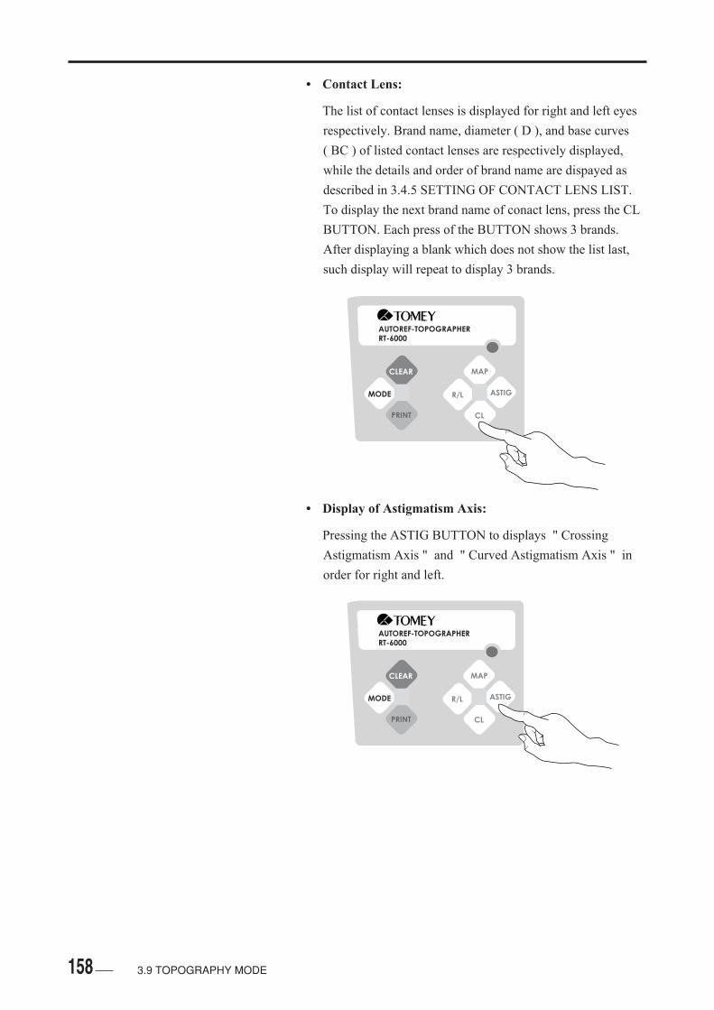
158 3.9 TOPOGRAPHY MODE
• Contact Lens:
The list of contact lenses is displayed for right and left eyes
respectively. Brand name, diameter ( D ), and base curves
( BC ) of listed contact lenses are respectively displayed,
while the details and order of brand name are dispayed as
described in 3.4.5 SETTING OF CONTACT LENS LIST.
To display the next brand name of conact lens, press the CL
BUTTON. Each press of the BUTTON shows 3 brands.
After displaying a blank which does not show the list last,
such display will repeat to display 3 brands.
• Display of Astigmatism Axis:
Pressing the ASTIG BUTTON to displays " Crossing
Astigmatism Axis " and " Curved Astigmatism Axis " in
order for right and left.
AUTOREF-TOPOGRAPHERRT-6000
CLEAR
MODE
MAP
R/L ASTIG
CL
AUTOREF-TOPOGRAPHERRT-6000
CLEAR
MODE
MAP
R/L ASTIG
CL

159
• In the display of " Crossing Astigmatism Axis ", the strong
and weak meidians are respectively displayed for right and
left eyes. These two meridians always cross at a right angle
( See 1.3 GLOSSARY ). No astigmatism axis is displayed
for an astigmatism of less than 0.20D.
• In the display of " Curved Astigmatism Axis ", the line
which iconnects the highest refractive values and that which
connects the lowest refractive values are displayed for right
and left respectively ( See 1.3 GLOSSARY ). No
astigmatism axis is displayed for an astigmatism of less than
1.0D.
<DISPLAY OF CROSSING ASTIGMATISM AXIS>
<DISPLAY OF CURVED ASTIGMATISM AXIS>
3.9 TOPOGRAPHY MODE
0:00ID 1
X
X
Cyl
MENICON Z
MENICON EX
MENICON EX
BC
BC
BC
D
D
D
7.70 9.2
7.75
7.75
9.2
9.6
BC
BC
BC
D
D
D
MENICON Z
MENICON EX
MENICON EX
7.70 9.2
7.75 9.2
9.67.75
33.79 ( 9.99)
33.80 ( 9.98)
33.79 ( 9.99)
135
45
0.00
40.74 ( 8.28)
43.87 ( 7.69)
42.25 ( 7.99)
X
X
Cyl
11
101
- 3.00
K1
K2
Avg
K1
K2
Avg101.5
96.5
91.5
86.581.576.571.566.561.556.550.549.047.546.044.543.041.540.038.537.035.529.024.019.014.0
9.0diopter
101.596.5
91.5
86.581.576.571.566.561.556.550.549.047.546.044.543.041.540.038.537.035.529.024.019.014.0
9.0
Absolute
0 0
90
135
90
135
45
X:Y:Z:
0.14- 0.03- 0.01
RSep/01/2002 00:00
0 0
90
135
90
135
45
X:Y:Z:
0.14- 0.03- 0.01
LSep/01/2002 00:00
! Cyl < 0.2D (Orthogonal)
ECC 0.10 ECC 0.00
0:00ID 1
X
X
Cyl
MENICON Z
MENICON EX
MENICON EX
BC
BC
BC
D
D
D
7.70 9.2
7.75
7.75
9.2
9.6
BC
BC
BC
D
D
D
MENICON Z
MENICON EX
MENICON EX
7.70 9.6
7.75 8.8
8.87.75
33.79 ( 9.99)
33.80 ( 9.98)
33.79 ( 9.99)
135
45
0.00
40.74 ( 8.28)
43.87 ( 7.69)
42.25 ( 7.99)
X
X
Cyl
11
101
- 3.00
K1
K2
Avg
K1
K2
Avg101.5
96.5
91.5
86.581.576.571.566.561.556.550.549.047.546.044.543.041.540.038.537.035.529.024.019.014.0
9.0diopter
101.596.5
91.5
86.581.576.571.566.561.556.550.549.047.546.044.543.041.540.038.537.035.529.024.019.014.0
9.0
Absolute
0 0
90
135
90
135
45
X:Y:Z:
0.14- 0.03- 0.01
RSep/01/2002 00:00
0 0
90
135
90
135
45
X:Y:Z:
0.14- 0.03- 0.01
LSep/01/2002 00:00
! Cyl < 1.0D (Instantaneous)
ECC 0.10 ECC 0.00

160
• When press the PRINT BUTTON, the whole information
being displayed in the screen will be printed in the video
printer or measured data and the map wil be printed in the
enclosed printer depending upon the information set ( See
3.4.3 SETTING OF TOPOGRAPHY ).
• Press the R/L BUTTON to displays the Single Map
( Right ).
AUTOREF-TOPOGRAPHERRT-6000
CLEAR
MODE
MAP
R/L ASTIG
CL
<IN PROCESS OF PRINTING>
AUTOREF-TOPOGRAPHERRT-6000
CLEAR
MODE
MAP
R/L ASTIG
CL
3.9 TOPOGRAPHY MODE
0:00ID 1
X
X
Cyl
MENICON Z
MENICON EX
MENICON EX
BC
BC
BC
D
D
D
7.70 9.2
7.75
7.75
9.2
9.6
BC
BC
BC
D
D
D
MENICON Z
MENICON EX
MENICON EX
7.70 9.2
7.75 9.2
9.67.75
33.79 ( 9.99)
33.80 ( 9.98)
33.79 ( 9.99)
135
45
0.00
40.74 ( 8.28)
43.87 ( 7.69)
42.25 ( 7.99)
X
X
Cyl
11
101
- 3.00
K1
K2
Avg
K1
K2
Avg101.5
96.5
91.5
86.581.576.571.566.561.556.550.549.047.546.044.543.041.540.038.537.035.529.024.019.014.0
9.0diopter
101.596.5
91.5
86.581.576.571.566.561.556.550.549.047.546.044.543.041.540.038.537.035.529.024.019.014.0
9.0
Absolute
0 0
90
135
90
135
45
X:Y:Z:
0.14- 0.03- 0.01
R
0 0
90
135
90
135
45
X:Y:Z:
0.14- 0.03- 0.01
LSep/01/2002 00:00
Printing
ECC 0.10 ECC 0.00
Sep/01/2002 00:00
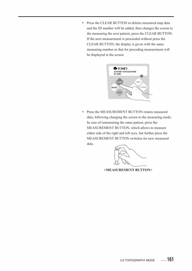
161
• Press the CLEAR BUTTON to deletes measured map data
and the ID number will be added, then changes the screen to
the measuring the next patient, press the CLEAR BUTTON.
If the next measurement is proceeded without press the
CLEAR BUTTON, the display is given with the same
measuring number as that for preceding measurement will
be displayed in the screen.
• Press the MEASUREMENT BUTTON retains measured
data, following changing the screen to the measuring mode.
In case of remeasuring the same patient, press the
MEASUREMENT BUTTON, which allows to measure
either side of the right and left eyes, but further press the
MEASUREMENT BUTTON switches for new measured
data.
AUTOREF-TOPOGRAPHERRT-6000
CLEAR
MODE
MAP
R/L ASTIG
CL
<MEASUREMENT BUTTON>
3.9 TOPOGRAPHY MODE
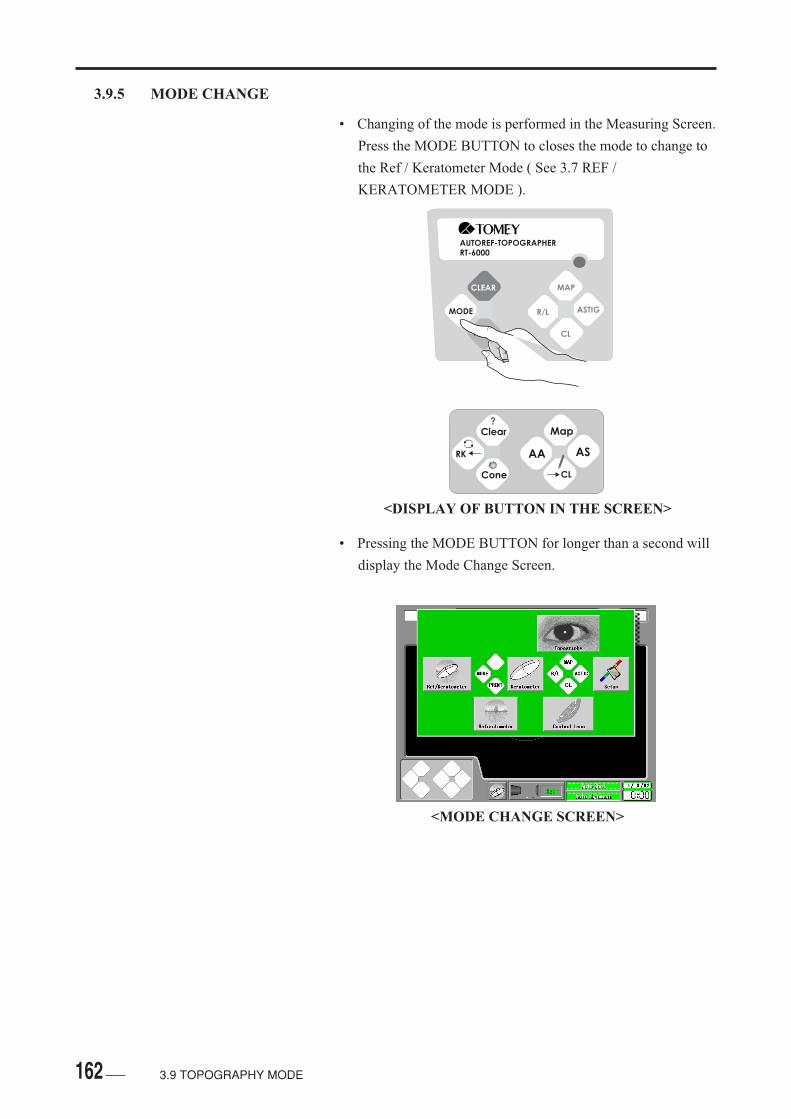
162
3.9.5 MODE CHANGE
• Changing of the mode is performed in the Measuring Screen.
Press the MODE BUTTON to closes the mode to change to
the Ref / Keratometer Mode ( See 3.7 REF /
KERATOMETER MODE ).
• Pressing the MODE BUTTON for longer than a second will
display the Mode Change Screen.
AUTOREF-TOPOGRAPHERRT-6000
CLEAR
MODE
MAP
R/L ASTIG
CL
<DISPLAY OF BUTTON IN THE SCREEN>
<MODE CHANGE SCREEN>
3.9 TOPOGRAPHY MODE
Clear
RK
Cone
AA
Map
CL
AS
?

163
AUTOREF-TOPOGRAPHERRT-6000
CLEAR
MODE
MAP
R/L ASTIG
CL
• Press the MAP BUTTON to finishing this mode and changes
to the Topography Mode ( See 3.9 TOPOGRAPHY
MODE ).
• Press the R / L BUTTON to finishes this mode and changes
to the Keratometer Mode ( See 3.6 KERATOMETER
MODE ).
• Press the ASTIG BUTON to finishes this mode and displays
the Setting Screen ( See 3.4 SETTING OF OPERATIONG
CONDITIONS ).
• Press the CL BUTTON to finishes this mode and changes
the Contact Lens Mode ( See 3.8 CONTACT LENS
MODE ).
• Press the MODE BUTTON to finishes the Mode Change
Screen and returns the Ref / Keratometer Mode.
3.9 TOPOGRAPHY MODE
164
( This page is left intentionally in blank )

1654.1 WARRANTY
4. INSPECTION AND MAINTENANCE
4.1 WARRANTY
One-Year Limited Warranty
The seller warrants this product to be free from defects in
material and workmanship under the normal use of this
product for one year or other term complying with local
regulations from the date of invoice issued by Seller to the
original purchaser.
Lamps, paper and other consumable items shall not be
convered by this warranty.
This warranty also shall NOT apply if the product has not
been installed, operated or maintained in accordance with
the OPERATOR MANUAL of Tomey Corporation (here in
after called " Tomey " ). Neither seller nor Tomey shall be
liable for any damages caused by purchaser's failure to
follow instruction for proper installation, use and
maintenance of the product.
This warranty is only appliciable to the new product and
DOES NOT cover any damage resulting from or caused by
accident or negligence, abuse, misuse, mishandling,
improper instalation, improper repair or improper
modification of this product, by persons other than personnel
duty authorized by Tomey, nor to a product whose serial
number or batch number is removed, altered or effaced.
THIS WARRANTY IS EXPRESSLY IN LIEU OF ANY
AND ALL OTHER WARRANTIES, EXPRESS OR
IMPLIED ( INCLUDING SPECIFICALLY, WITHOUT
LIMITING THE GENERALITY OF THE FOREGOING,
ALL WARRANTIES OF MERCHANTABILITY AND
FITNESS FOR A PARTICULAR PURPOSE ), AND ALL
OTHER OBILIGATION AND LIABILITY ON THE PART
OF SELLER AND TOMEY. NEITHER SELLER NOR
TOMEY SHALL BE LIABLE FOR INCIDENTAL,
CONSEQUENTIAL OR SPECIAL DAMAGES UNDER
ANY CIRCUMSTANCES OR FOR MORE THAN
REPAIR, REPLACEMENT OR REFUND OF THE
PURCHASE PRICE OF DEFECTIVE GOODS.
166
4.2 ROUTINE MAINTENANCE
• Care is to be given not to use alcohol for disinfec-tion purpose for cleaning the cover for main unitand the cone of this instrument.
• Do not organic solvents, such as thinner, ben-zene, and acetone, for cleaning this instrument.The surface of the instrument enclosures mayotherwise be eroded or degraded.
• Care is to be given not to stain the measurementwindow with finger marks or dust.
• Press the dust cover on the instrument while net being used.
• If the instrument is left as unused for longer than one week,
disconnect the power cord from the receptacle.
• Use dry soft cloth for cleaning the instrument. In case of
excessive stains, use a piece of dry soft cloth after being
soaked in the solution of a neutral cleanser and squeezed for
proper dehydration.
• Clean the inside of the cone with soft cloth occasionally.
• It is recommended that, for the purpose of confirming the
internal functions of the instrument, the accuracy of the
instrument is checked with the use of attached model eye.
Sufficient care is to be taken not to hit or damage the cone
when checking the instrument functions and the cone.
4.2 ROUTINE MAINTENANCE

1674.3 REPLACING OF SUPPLIES
4.3 REPLACING OF SUPPLIES
4.3.1 LOADING OF PRINTING PAPER ROLL
• Specified Printer Paper shall be used or theprinter may otherwise be malfunctioned.
• Changing the Printer Paper when it shows the red-colored
lines on both sides.
• Pull the Printer Cover to yourself.
• Take out the used Printer Paper Roll.
• Load the new Printer Paper Roll into the Printer.
• The Printer Paper, if installed up side down willnot give printer.
<RED LINES>
<REMOVING THE PRINTER COVER>
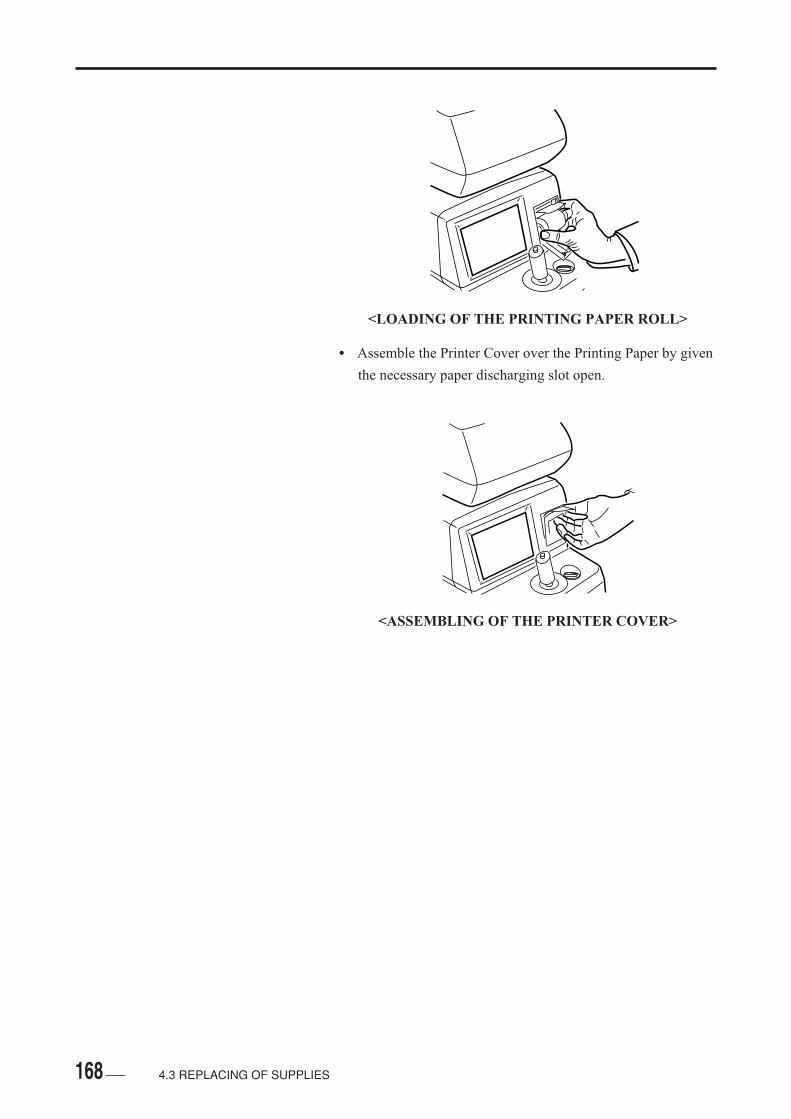
168
<LOADING OF THE PRINTING PAPER ROLL>
• Assemble the Printer Cover over the Printing Paper by given
the necessary paper discharging slot open.
<ASSEMBLING OF THE PRINTER COVER>
4.3 REPLACING OF SUPPLIES

169
4.3.2 CHANGING OF THE FUSE
• Be sure to disconnect the Power Cord beforechanging the fuse.
• In case the instrument is caused with any mal-function after the fuse is replaced, some othertrouble than by fuse may have been caused. Ifthis happens, turn the power off immediately andask our local representative for countermea-sures.
• The fuse is to be of 250V T2. 5A.
• Turn the Power Switch off.
• Disconnect the Power Switch off.
• Turn the Fuse Case counterclockwise to remove it.
• Replacing the used fuses with the new parts. The fuses must
be for 250V T25A.
• Turn the Fuse Case clockwise by pressing the case and fix it
firmly.
<REMOVING OF THE FUSES>
4.3 REPLACING OF SUPPLIES

170
4.3.3 REPLACING OF THE CHIN REST PAPER
• Pull out two fixed pins from the Chin Rest.
• Place the new Chin Rest Paper on the Chin Rest and again
secure the paper with the paper fixed pins.
<LOADING OF THE CHIN REST PAPER>
4.3 REPLACING OF SUPPLIES

171
4.4 STORING
• Be sure to place the Dust Preventive Cover overthe instrument.
• Place the instrument in a place where the instru-ment is not subjected to water and / or chemicals.
• Store the instrument in a place where it is freefrom direct sunbeams, high temperature, mois-ture, dust, and salts or sulfur contained air whichmay otherwise cause adverse effects.
• Store the instrument in a stable place which isnot subjected to any inclination, vibration, andstock.
• Do not store the instrument in or near a chemi-cals storing or gas generating place.
4.4 STORING

172
4.5 DISPOSAL OF PACKING MATERIALS
• For efficient disposal of packing materials, sortand dispose them by material kind, inaccordancewith your local rules and regulations.
4.5 DISPOSAL OF PACKING MATERIALS

173
5. TROUBLESHOOTING
• No other countermeasures than specified in thisManual shall be taken.
• In case no correction can be made by the follow-ing countermeasures, counsult your local repre-sentative.
5.1 GENERAL TROUBLESHOOTING
BEFORE JUDGING THE INSTRUMENT AS A
TROUBLE WITH ANY MECHANICAL FAILURE,
CHECK ON THE FOLLOWING ITEMS.
• The upper unit of the instrument does not move to the
front/rear and left/right directions properly, by joystick
operation.
Check to see if the fixed screws are left as being fixed.
• The Power Lamp and the monitor do not work properly
even if the Power Switch is turned ON.
Check to see if the fixed screws are left as being fixed.
Check to see if the fuse is proper.
• The Power Switch is ON, but the monitor is OFF.
Check to see if the Power Plug is connected witht the
receptable.
Check to see if the instrument is in its electric saving
condition.
Check to see if the screen light is too dark.
• No printing is obtained when pressing the PRINT
BUTTON.
Check to see the Printing Paper has run out.
Check to see if the Paper Roll has been placed upside down.
Check to see if the instrument is in its electric saving
condition.
5 TROUBLESHOOTING

174
• Measured values are erroneous, without the error
indication in the display screen.
Check to see if the Measuring Window is stained.
Check to see if the eye to be examined has any abnormal
condition.
Check to see if the instrument is in its electric saving
condition.
5 TROUBLESHOOTING

1755 TROUBLESHOOTING
5.2 ERROR MESSAGE
• RANKING IDENTIFICATION
The messages are ranked in five types (A thought E),
depending on the degree and type of problem.
- rank A: If the message is not erased by re-switching the
power on, discontinue the operation and consult with your
representative.
- rank B Perform the operation of the equipment by giving
care for the operating procedures and measurement data. If
the operation is not restored, consult with your
representative.
- rank C Check to seeif the surrounding equipment, such as
printer and the computers which are connected to the main
unit, are proper, and also check on the setup of the main
unkit to see if it has been made as specified.
- rank D Perform your measurement by checking on the
eyelids and eyelash of the eye to be examined.
- rank E Other.
5.2.1 START UP
• Error: Cone Motor (rank A)
- Description:
Keratometer or Topography may not take correct
measurement of the base curves of CL.
- Countermeasure:
If the message is not erased by re-switching the power on,
discontinue the operation and consult with your
representative.
• Error: Fog Motor (rank A)
- Description:
The Refractometer related function has problems.
Refractometer measurement may possibly be correctly
made.
- Countermeasure:
If the message is not erased by re-switching the power on,
discontinue the operation and consult with your
representative.

176
• Error: CCD Motor (rank A)
- Description:
The Refractometer related function has problems.
Refractometer measurement may possibly be correctly
made.
- Countermeasure:
If the message is not erased by re-switching the power on,
discontinue the operation and consult with your
representative.
• Error: Alignment Motor (rank A)
- Description:
The alignment related function has problems. The joystick
does not work its up/down movement or auto alignment,
thereby making it unable to correctly measure the base
curves of contact lenses.
- Countermeasure:
No operation of the up/down joystick movement and auto
alignment. Please contact your representative.
• Error: Alignment Com (rank A)
- Description:
The enclosed computer may possibly have been disordered.
- Countermeasure:
If the message is not erased by re-switching the power on,
discontinue the operation and consult with your
representative.
• Error: Ref Com (rank A)
- Description:
The enclosed computer may possibly have been disordered.
- Countermeasure:
If the message is not erased by re-switching the power on,
discontinue the operation and consult with your
representative.
5 TROUBLESHOOTING

1775 TROUBLESHOOTING
• Error: Disk (rank A)
- Description:
The enclosed computer may possibly have been disordered.
- Countermeasure:
If the message is not erased by re-switching the power on,
discontinue the operation and consult with your
representative.
• Error: Alignment ID (rank B)
- Description:
The enclosed computer may possibly have been disordered.
- Countermeasure:
If the message is not erased by re-switching the power on,
discontinue the operation and consult with your
representative.
• Error: Ref ID (rank B)
- Description:
The enclosed computer may possibly have been disordered.
- Countermeasure:
If the message is not erased by re-switching the power on,
discontinue the operation and consult with your
representative.
• Error: Network communication (rank B)
- Description:
The problem of communications with the computer on the
other end.
- Countermeasure:
Check the power sources and the cable of the computer of
the other end. Also, check the setup of the network of the
main unit.

178
5.2.2 REFRACTOMETER / KERATOMETER
• Error: Cone Motor (rank A)
- Description:
Keratometer or Topography may not take correct
measurement of the base curves of CL.
- Countermeasure:
If the message is not erased by re-switching the power on,
discontinue the operation and consult with your
representative.
• Error: Fog Motor (rank A)
- Description:
The Refractometer related function has problems.
Refractometer measurement may possibly be correctly
made.
- Countermeasure:
If the message is not erased by re-switching the power on,
discontinue the operation and consult with your
representative.
• Error: CCD Motor (rank A)
- Description:
The Refractometer related function has problems.
Refractometer measurement may possibly be correctly
made.
- Countermeasure:
If the message is not erased by re-switching the power on,
discontinue the operation and consult with your
representative.
• Error: Alignment Motor (rank A)
- Description:
The alignment related function has problems. The joystick
does not work its up/down movement or auto alignment,
thereby making it unable to correctly measure the base
curves of contact lenses.
- Countermeasure:
No operation of the up/down joystick movement and auto
alignment. Please contact your representative.
5 TROUBLESHOOTING

1795 TROUBLESHOOTING
• Error: Alignment Com (rank A)
- Description:
The enclosed computer may possibly have been disordered.
- Countermeasure:
If the message is not erased by re-switching the power on,
discontinue the operation and consult with your
representative.
• Error: Ref Com (rank A)
- Description:
The enclosed computer may possibly have been disordered.
- Countermeasure:
If the message is not erased by re-switching the power on,
discontinue the operation and consult with your
representative.
• Error: ef Data (rank A)
- Description:
The enclosed computer may possibly have been disordered.
- Countermeasure:
If the message is not erased by re-switching the power on,
discontinue the operation and consult with your
representative.
• Error: PD Correction (rank B)
- Description:
PD measuring function has the problem with no display of
correct measurement value.
- Countermeasure:
Correct PD (Pupillary Distance) is not measured. Please
contact your representative.

180 5 TROUBLESHOOTING
5.2.3 KERATOMETER
• Error: Alignment Motor (rank A)
- Description:
The alignment related function has problems. The joystick
does not work its up/down movement or auto alignment,
thereby making it unable to correctly measure the base
curves of contact lenses.
- Countermeasure:
No operation of the up/down joystick movement and auto
alignment. Please contact your representative.
• Error: Caliburation (rank A)
- Description:
The enclosed computer may possibly have been disordered.
- Countermeasure:
If the message is not erased by re-switching the power on,
discontinue the operation and consult with your
representative.
• Error: No Kerato Ring (rank D)
- Description:
This message is displayed when the rings are not correctly
reflected to the cornea.
- Countermeasure:
Have the Patient widely open the eye so that the lid or the
eyelash does not interfere the measurement ring, or advise to
repeat blinkings not to dry the cornea for re-measurement.
• Error: Data (rank D)
- Description:
This message is displayed when the rings are not correctly
reflected to the cornea.
- Countermeasure:
Have the Patient widely open the eye so that the lid or the
eyelash does not interfere the measurement ring, or advise to
repeat blinkings not to dry the cornea for re-measurement.

1815 TROUBLESHOOTING
• Check Image (rank D)
- Description:
This message is displayed when the rings are not correctly
reflected to the cornea.
- Countermeasure:
Have the Patient widely open the eye so that the lid or the
eyelash does not interfere the measurement ring, or advise to
repeat blinkings not to dry the cornea for re-measurement.
• Error: Few Number of Kerato (rank D)
- Description:
This message is displayed when the rings are not correctly
reflected to the cornea.
- Countermeasure:
Have the Patient widely open the eye so that the lid or the
eyelash does not interfere the measurement ring, or advise to
repeat blinkings not to dry the cornea for re-measurement.
5.2.4 TOPOGRAPHY
• Error: Cone Motor (rank A)
- Description:
No correct Keratometer and Topography measurements of
CL base curves arise occasionally.
- Countermeasure:
If the message is not erased by re-switching the power on,
discontinue the operation and ask your representative for
remedy.
• Error: Alignment Motor (rank A)
- Description:
Alignment related function has the problem. Joystick up/
down movement, auto alignment, and/or correct CL base
curve measurement cannot be made.
- Countermeasure:
No operation of the up/down Joystick movement and auto
alignment. Please ask your represantative.
182
• Error: Bad Image (rank D)
- Description:
This message is displayed when the rings are not correctly
reflected to the cornea.
- Countermeasure:
Have the Patient widely open the eye so that the lid or the
eyelash does not interfere the measurement rings or advise to
repeat blinkings not to dry the cornea for re-measurement.
• Error: Few Number of Kerato (rank D)
- Description:
This message is diplayed when the rings are not correctly
reflected to the cornea.
- Countermeasure:
Have the Patient widley open the eye so that the lid or the
eyelash does not interfere the measurement rings or advise to
repeat blinkings not to dry the cornea for re-measurement.
• Cyl < 0.2D <Orthogonal> (rank E)
- Description:
The astigmatic axis is not displayed with weak corneal
astigmatism (direct astigmatic axis).
- Countermeasure:
The astigmatic axis is not displayed due to the corneal
astigmatism of less than 0.2D.
• Cyl < 1.0D <Instantaneous> (rank E)
- Description:
The astigmatic axis is not displayed with weak corneal
astigmatism (direct astigmatic axis).
- Countermeasure:
The astigmatic axis is not displayed due to the corneal
astigmatism of less than 1.0D.
5 TROUBLESHOOTING
183
• Error: 1.0 < Offset (rank E)
- Description:
The message is displayed when alignment is largely shifted
from the center of the cornea.
- Countermeasure:
Take remeasurement by advising the Patient for fixed eye.
• Moving the Cone Forward (rank E)
- Description:
The message is displayed when press the joystick button
without projecting the cone.
- Countermeasure:
Push the cone out by pulling the main unit to your side.
• Moving the Joystick Backward / Wait until (rank E)
- Description:
The message is displayed when press the operation is
changed to Topography mode, if auto cone movement has
been set.
- Countermeasure:
Push the cone out by pulling the main unit to your side.
• Move the Joystick Backward (rank E)
- Description:
The message is displayed when press the cone project button
without pulling the head to your side.
- Countermeasure:
When press the button to push the cone out, pull the head to
your side.
• Error: Ring Center (rank E)
- Description:
The message is displayed when the ring center is largely
shifted from the corneal center.
- Countermeasure:
Take remeasurement by advising the Patient for fixed eye.
5 TROUBLESHOOTING
184
• No Image File (rank E)
- Description:
The message is displayed when the image have been out of
memory of the instrument.
- Countermeasure:
No analized image is observed. Print after taking the
measurement.
5.2.5 PRINTER
• Printer Error (rank C)
- Description:
This message is displayed when the enclosed printer is
disordered or the printer paper is not in position or has run
out.
- Countermeasure:
Make sure that the cover for enclosed printer and the printer
paper are in position.
• No Paper (rank C)
- Description:
The message is displayed when the paper for digital color
printer has run out.
- Countermeasure:
Change the digital color printer paper to new roll.
• Offline (rank C)
- Description:
The message is displayed when data is not sent to the digital
color printer.
- Countermeasure:
Turn the power for digital color printer on. Then, check the
cable connection.
5 TROUBLESHOOTING
185
• Change Cartridge (rank C)
- Description:
The message is displayed when the ink sheet for digital color
printer has run out.
- Countermeasure:
Change the ink sheet for digital color printer to new roll.
• No Printer (rank C)
- Description:
The message is displayed when data is not sent to the digital
color printer.
- Countermeasure:
Turn the power for digital color printer on. Then, check the
cable connection.
• Printing: Wait a Moment (rank E)
- Description:
The message is displayed when data is not sent to the digital
color printer, or when other operation is given while data
transmission is in process.
- Countermeasure:
Do not proceed in other operation until printing is finished.
5.2.6 DATA COMMUNICATION
• Error: ID (rank C)
- Description:
This message is displayed when the wrong ID is entered.
- Countermeasure:
Make sure that inputted correct ID.
5 TROUBLESHOOTING

186
• No Response (rank C)
- Description:
The message is displayed when there is the problem with the
communications with the receiving computer.
- Countermeasure:
Check on the computer which receives communications
including the connection cables.
• Sharing Error (rank C)
- Description:
The message is displayed when no access can be made since
the file to be deleted is being used by computer.
- Countermeasure:
Wait operation for a while. If the message is not erased,
check on the computer which receives communications.
• Data is not Transfered (rank C)
- Description:
The message is displayed when data cannot be sent due to
the ID which has not be set.
- Countermeasure:
Check on the computer receiving communications and the
setup condition of the main unit including the connection
cables.
• Data was not Transfered (rank C)
- Description:
The message is displayed when data communications with
the side of the computer have not been completed in the
proper procedures.
- Countermeasure:
Check on the computer receiving communications and the
setup condition of the main unit including the connection
cables.
5 TROUBLESHOOTING

187
6. SUPPLIES• The following supply parts are available from Tomey's
distributor from who you purchased your instrument.
Paper Roll for Built-in Printer
Chin Rest Paper ( 100 sheets / set )
Fuse: 250V T2.5A
6 SUPPLIES
188
( This page is left intentionally in blank )
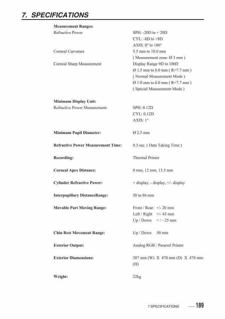
189
7. SPECIFICATIONSMeasurement Ranges:
Refractive Power SPH: -20D to + 20D
CYL: -8D to +8D
AXIS: 0° to 180°Corneal Curvature 5.5 mm to 10.0 mm
( Measurement zone: Ø 3 mm )
Corneal Sharp Measurement Display Range 9D to 100D
Ø 1.5 mm to 8.0 mm ( R=7.7 mm )
( Normal Measurement Mode )
Ø 1.0 mm to 6.0 mm ( R=7.7 mm )
( Special Measurement Mode )
Minimum Display Unit:
Refractive Power Measurement: SPH: 0.12D
CYL: 0.12D
AXIS: 1°
Minimum Pupil Diameter: Ø 2.5 mm
Refractive Power Measurement Time: 0.3 sec. ( Data Taking Time )
Recording: Thermal Printer
Corneal Apex Distance: 0 mm, 12 mm, 13.5 mm
Cylinder Refractive Power: + display, - display, +/- display
Interpupillary DistanceRange: 50 to 86 mm
Movable Part Moving Range: Front / Rear: +/- 20 mm
Left / Right +/- 43 mm
Up / Down + / - 25 mm
Chin Rest Movement Range: Up / Down 50 mm
Exterior Output: Analog RGB / Pararrel Printer
Exterior Diamensions: 307 mm (W) X 470 mm (D) X 470 mm
(H)
Weight: 22kg
7 SPECIFICATIONS

190
( This page is left intentionally in blank )

Authorized Tomey Service Centers:
Headquarters, Pacific rim
Tomey Corporation
2-11-33 Noritakeshinmachi
Nishi-ku, Nagoya 451-0051 JAPAN
Tel: +81 52-581-5327
Fax: +81 52-561-4735
Europe
Tomey GmbH
Am Weichselgarten 19a
91058 Erlangen GERMANY
Tel: +49 9131-77710
Fax: +49 9131-777120
Manufacturer
Tomey Corporation
2-11-33 Noritakeshinmachi
Nishi-ku, Nagoya 451-0051 JAPAN
Tel: +81 52-581-5327
Fax: +81 52-561-4735
EC-Representative
Tomey GmbH
Am Weichselgarten 19a
91058 Erlangen GERMANY
Tel: +49 9131-77710
Fax: +49 9131-777120

ID: 0409