operator control station demonstration case · · 2017-07-11user manual for the he500ocs995,...
TRANSCRIPT

User Manual for theHE500OCS995,
HE500OCS997, and HE500OCS999
Operator ControlStation
Demonstration Case
Second Edition29 June 1999
MAN0282-02


PREFACE 29 JUN 1999 PAGE 3
PREFACE
This manual explains how to use the Horner Electric Operator Control Station Demonstration Cases(HE500OCS999/997/995).
Copyright (C) 1999 Horner Electric, Inc., 640 North Sherman Drive Indianapolis, Indiana 46201. All rightsreserved. No part of this publication may be reproduced, transmitted, transcribed, stored in a retrievalsystem, or translated into any language or computer language, in any form by any means, electronic,mechanical, magnetic, optical, chemical, manual or otherwise, without the prior agreement and writtenpermission of Horner Electric, Inc.
All software described in this document or media is also copyrighted material subject to the terms andconditions of the Horner Software License Agreement.
Information in this document is subject to change without notice and does not represent a commitment onthe part of Horner Electric, Inc.
Cscape, CsCAN, and SmartStack are trademarks of Horner Electric.
For user manual updates, contact Horner Electric Advanced ProductsGroup, Technical Support Division, at (317) 916-4274 or visit ourwebsite at www.heapg.com.

PAGE 4 29 JUN 1999 PREFACE
LIMITED WARRANTY AND LIMITATION OF LIABILITY
Horner Electric, Inc. ("HE") warrants to the original purchaser that the Operator Control StationDemonstration Case manufactured by HE are free from defects in material and workmanship undernormal use and service. The obligation of HE under this warranty shall be limited to the repair orexchange of any part or parts which may prove defective under normal use and service within two (2)years from the date of manufacture or eighteen (18) months from the date of installation by the originalpurchaser whichever occurs first, such defect to be disclosed to the satisfaction of HE after examinationby HE of the allegedly defective part or parts. THIS WARRANTY IS EXPRESSLY IN LIEU OF ALLOTHER WARRANTIES EXPRESSED OR IMPLIED INCLUDING THE WARRANTIES OFMERCHANTABILITY AND FITNESS FOR USE AND OF ALL OTHER OBLIGATIONS OR LIABILITIESAND HE NEITHER ASSUMES, NOR AUTHORIZES ANY OTHER PERSON TO ASSUME FOR HE, ANYOTHER LIABILITY IN CONNECTION WITH THE SALE OF THESE OPERATOR CONTROL STATIONDEMONSTRATION CASE. THIS WARRANTY SHALL NOT APPLY TO THIS OPERATOR CONTROLSTATION DEMONSTRATION CASE OR ANY PART THEREOF WHICH HAS BEEN SUBJECT TOACCIDENT, NEGLIGENCE, ALTERATION, ABUSE, OR MISUSE. HE MAKES NO WARRANTYWHATSOEVER IN RESPECT TO ACCESSORIES OR PARTS NOT SUPPLIED BY HE. THE TERM"ORIGINAL PURCHASER", AS USED IN THIS WARRANTY, SHALL BE DEEMED TO MEAN THATPERSON FOR WHOM THE OPERATOR CONTROL STATION DEMONSTRATION CASES AREORIGINALLY INSTALLED. THIS WARRANTY SHALL APPLY ONLY WITHIN THE BOUNDARIES OFTHE CONTINENTAL UNITED STATES.
In no event, whether as a result of breach of contract, warranty, tort (including negligence) or otherwise,shall HE or its suppliers be liable of any special, consequential, incidental or penal damages including,but not limited to, loss of profit or revenues, loss of use of the products or any associated equipment,damage to associated equipment, cost of capital, cost of substitute products, facilities, services orreplacement power, down time costs, or claims of original purchaser's customers for such damages.
To obtain warranty service, return the product to your distributor with a description of theproblem, proof of purchase, post paid, insured and in a suitable package.
ABOUT PROGRAMMING EXAMPLES
Any example programs and program segments in this manual or provided on accompanying diskettes areincluded solely for illustrative purposes. Due to the many variables and requirements associated with anyparticular installation, Horner Electric cannot assume responsibility or liability for actual use based on theexamples and diagrams. It is the sole responsibility of the system designer utilizing the Operator ControlStation Demonstration Case to appropriately design the end system, to appropriately integrate theOperator Control Station Demonstration Case and to make safety provisions for the end equipment as isusual and customary in industrial applications as defined in any codes or standards which apply.
Note: The programming examples shown in this manual are for illustrative purposes only. Proper machine operation is the sole responsibility of the system integrator.

PREFACE 29 JUN 1999 PAGE 5
Revisions to This Manual
This version (MAN0282-02) of the Operator Control Station Demonstration Case User Manual containsthe following revisions and additions:
Added a new demonstration case model (HE500OCS995) in Chapter One, Section 1.2.
Revised product description in Section 1.2.2 (a) to include HE500OCS995.
Revised demonstration procedures in Chapter Two to include the HE800OCS995.
Added a new wiring diagram for HE500OCS995 in Chapter Three, Figure 3.3.

PAGE 6 29 JUN 1999 PREFACE
PREFACE 29 JUN 1999 PAGE 7
TABLE OF CONTENTS
PREFACE................................................................................................................................................3LIMITED WARRANTY AND LIMITATION OF LIABILITY ..........................................................................4ABOUT PROGRAMMING EXAMPLES ....................................................................................................4CHAPTER 1: INTRODUCTION AND SETUP ..........................................................................................9
1.1 General..................................................................................................................................... 91.2 Models Available....................................................................................................................... 9
1.2.1 OCS999 OCS Demonstration Case.................................................................................... 91.2.2 OCS997 and OCS995 OCS Demonstration Case..............................................................10
CHAPTER 2: OPERATION ...................................................................................................................132.1 General....................................................................................................................................132.2 OCS999 Demonstration Procedures.........................................................................................13
2.2.1 OCS100 Demonstration Program ......................................................................................132.2.2 OCS200 Demonstration Program ......................................................................................14
2.3 OCS997and OCS995 Demonstration Procedures.....................................................................182.3.1 OCS100 Demonstration Program ......................................................................................18
CHAPTER 3: DEMONSTRATION CASE WIRING AND HARDWARE ..................................................193.1 General....................................................................................................................................193.2 Wiring Diagrams ......................................................................................................................19
3.2.1 OCS999............................................................................................................................193.2.2 OCS997 and OCS995.......................................................................................................20
3.3 Configuration Port Connections................................................................................................213.3.1 OCS999............................................................................................................................213.3.2 OCS997 and OCS995.......................................................................................................22
3.4 Network Connections ...............................................................................................................223.4.1 OCS999............................................................................................................................223.4.2 OCS997 and OCS995.......................................................................................................22
3.5 Power Connections ..................................................................................................................233.5.1 OCS999............................................................................................................................233.5.2 OCS997 and OCS995.......................................................................................................23

PAGE 8 29 JUN 1999 PREFACE

CHAPTER 1: INTRO./SETUP 29 JUN 1999 PAGE 9
CHAPTER 1: INTRODUCTION AND SETUP
1.1 General
The Horner Operator Control Station (OCS) Demonstration Case serves as a visual tool to demonstratevarious functions that an OCS can be programmed to perform. The OCS Demonstration Case comesfully equipped with the necessary equipment, cables, connectors, and software to performdemonstrations. No assembly or installation is required.
1.2 Models Available
Three models of the OCS Demonstration Cases are available – the HE500OCS999, HE500OCS997, andHE500OCS995. Although they are useful for training and demonstrating the capabilities of the OCS,each model has unique features designed to meet the needs of different customers.
Note: The OCS997 and the OCS995 are similar, but they use a different I/O module and have differentwiring.
1.2.1 OCS999 OCS Demonstration Case
a. Product Description
The larger model, the OCS999, is equipped with two Operator Control Station units (OCS100 andOCS200) and provides a wide variety of functional OCS demonstrations. Network functions are easilydemonstrated using the OCS999. The unit is especially helpful to companies wanting to conduct more in-depth OCS training and to individuals in the Sales and Marketing fields.
The OCS999 Demonstration Case contains:
a. 1 HE500OCS100 j. 1 type K temperature probeb. 1 HE500OCS200 k. 1 power cordc. 2 HE800DIQ611 SmartStack I/O Modules l. 16 discrete input switchesd. 1 HE800THM100 SmartStack I/O Module m. 16 discrete output lightse. 1 HE800DAC101 SmartStack I/O Module n. 1 thermocouple plugf. 1 power supply o. 1 analog meterg. 1 power switch p. 2 OCS configuration portsh. 2 network terminating resistors (connector with 120Ω resistor between CN_H and CN_L)
q. 2 CsCAN network ports
i. 1 straight through 9-pin programming cable (HE693CBL222)
Two SmartStack I/O Modules are provided with the OCS100 in the OCS999 - a Discrete 8 In/8 OutModule (DIQ611) and a Four-Channel Thermocouple Module (THM100). Eight panel lights serve asdiscrete outputs from the DIQ611, and eight panel switches serve as discrete inputs to the DIQ611.Connected to Channel 1 of the THM100 is a Type K Thermocouple input into which the providedtemperature probe can be plugged. There is also an OCS100 Configuration port that can be connectedto the COM port of the user’s PC by using the provided 9-pin cable.
PAGE 10 29 JUN 1999 CHAPTER 1: INTRO./SETUP
The OCS200 also has two SmartStack I/O Modules provided with it in the OCS999 - a Discrete 8 In/8 OutModule (DIQ611) and a Four-Channel Analog Output Module (DAC101). Eight panel lights serve asdiscrete outputs from the DIQ611, and eight panel switches serve as discrete inputs to the DIQ611.Connected to Channel 1 of the DAC101 is an analog meter that reads the voltage output. There is also anOCS200 Configuration port that can be connected to the COM port of the user’s PC by using the provided9-pin cable.
b. Setup
Both the OCS100 and OCS200 units contained in the OCS999 come with a demonstration ladderprogram loaded into memory. To setup the case for operation:
1. Connect the temperature probe into the front panel thermocouple input.2. Connect the power cord to the front socket and plug into 100 – 250VAC @ 50 - 60 Hz.3. Turn on the power switch to run each OCS unit through a self-test and bring up an introduction screen with instructions.
For information specific to the OCS100/200 or the SmartStack modules, refer to the appropriate usermanuals.
1.2.2 OCS997 and OCS995 OCS Demonstration Case
a. Product Description
The smaller models, the OCS997 and OCS995, are equipped with one Operator Control Station unit(OCS100) and serve as starter kits. The starter kit offers two key benefits: Exceptional value and theopportunity for the user to become familiar with programming the OCS before integrating the unit into asystem. Attractively priced, the all-inclusive starter kits cost less than purchasing the necessaryequipment and parts separately. The starter kits allow the user to work with the OCS program withouthaving to first wire and formally install the unit. They are easy to disassemble and are readily installedinto a system.
Note: The OCS997 and the OCS995 are similar, but they use a different I/O module and have differentwiring.
The OCS997 Demonstration Case contains:
a. 1 HE500OCS100 e. 16 Discrete Input Switchesb. 1 HE800DIQ611 f. 16 Discrete Output Switchesc. 1 Power Supply g. 1 Straight-through 9-pin
programming cable (HE693CBL222)d. 1 Power Cord
One SmartStack I/O Module is provided with the OCS100 in the OCS997 Demonstration Case. TheOCS997 contains a Discrete 8 In/8 Out Module (DIQ611). Eight panel lights serve as discrete outputsfrom the DIQ611, and eight panel switches serve as discrete inputs to the DIQ611.
CHAPTER 1: INTRO./SETUP 29 JUN 1999 PAGE 11
The OCS995 Demonstration Case contains:
a. 1 HE500OCS100 e. 16 Discrete Input Switchesb. 1 HE800DIQ616 f. 16 Discrete Output Switchesc. 1 Power Supply g. 1 Straight-through 9-pin
programming cable (HE693CBL222)d. 1 Power Cord
One SmartStack I/O Module is provided with the OCS100 in the OCS995 Demonstration Case. TheOCS995 contains a Discrete 8 In/8 Out Module (DIQ616). Eight panel lights serve as discrete outputsfrom the DIQ616, and eight panel switches serve as discrete inputs to the DIQ616.
b. Setup
The OCS100 unit contained in the OCS997 and OCS995 comes with a demonstration ladder programloaded into memory. To setup the case for operation:
1. Connect the power cord to the power supply and plug into 100 – 250VAC @ 50 - 60 Hz.2. Connect power supply to power plug in panel.
Note: During the startup procedure, there is notification that there is no network power and that the network is disabled. This is a normal indication, because there is no network to connect to.
For information specific to the OCS100/200 or the SmartStack modules, refer to the appropriate usermanuals.

PAGE 12 29 JUN 1999 CHAPTER 1: INTRO./SETUP
NOTES

CHAPTER 2: OPERATION 29 JUN 1999 PAGE 13
CHAPTER 2: OPERATION
2.1 General
Chapter Two provides procedures for using the demonstration programs in the OCS999, OCS997, andOCS995.
2.2 OCS999 Demonstration Procedures
Note: The eight panel lights in the demonstration case represent discrete outputs, and the eight panelswitches represent discrete inputs.
2.2.1 OCS100 Demonstration Program
When the demonstration case is first powered up, the OCS100 runs through a series of self-tests. Ifeverything passes, both the ‘OK’ light and the ‘RUN’ light turns on, and the ladder program that is loadedinto the OCS100 executes.
1. Sequenced Light Display
The program in the OCS100 starts with a title screen. Pressing the ↑ key advances to the next screenand prompts the pressing of F7 for a sequenced light demonstration. Pressing F8 stops the lightdemonstration. The F7 key corresponds to %K7 (K for Key) in the ladder logic and pressing F7 closesthe normally open %K7 contact. This sets a latch and starts a sequential light demonstration on theOCS100 Discrete Output lights. The F8 key corresponds to %K8 in the ladder logic and pressing F8closes the normally open %K8 contact. This releases the latch that was set by the F7 key and stops thelights. The lights are controlled by the DIQ611 outputs on the OCS100.
2. Pulling Up a Series of Information Screens
Pressing the ↑ key advances to the next screen, which prompts the user to flip Switch 1 for OCSprogramming features. The OCS100 Discrete Input Switch 1 is connected to I1 of the DIQ611 andcorresponds to %I1 in the OCS100 ladder logic. Turning Switch 1 on closes the normally open %I1contact and executes a loop of code that scrolls through a group of information screens. Turning Switch1 off opens the %I1 contact.
3. Bit Shift Demonstration
Pressing the ↑ key advances to the next screen, which prompts the pressing of F1 for a bit shiftdemonstration. Press F2 to stop the demonstration. The F1 key corresponds to %K1 in the ladder logic,and F2 corresponds to %K2. Pressing F1 closes the normally open %K1 contact which sets a latch.Using bit shifting functions, a message scrolls across the screen. Pressing F2 closes the normally open%K2 contact which then releases the latch.
4. Using OCS100 to Send Global Analog Data over Network to OCS200
Pressing the ↑ key advances to the next screen, which prompts the flipping of Switch 2. Thisdemonstration sends global data to the CsCAN network that can be used by any other device on thenetwork. In this case, the OCS200 is programmed to use it. OCS100 Discrete Input Switch 2 isconnected to I2 of the DIQ611 on the OCS100 and corresponds to %I2 in the ladder logic. When Switch2 is turned on, the normally open %I2 contact is closed which then sets bit 1 of Global Output word 1(%AQG1). The values 16,000 and –16,000 (49,535 in signed integer form) are alternately placed in thesame Global Output word, %AQG1.

PAGE 14 29 JUN 1999 CHAPTER 2: OPERATION
With this setup, the value in %AQG1 alternates between 16,001 and –15,999 (49,536 in signed integerform) since bit 1 is constantly updated to 1 as long as Switch 2 is on. The ladder logic in the OCS200monitors the Global Input word %AIG1 and directs the values to the DAC101 output as long as bit 1 ishigh (which makes the analog meter jump between +5 and –5 Volts). Turning the OCS100 Discrete InputSwitch 2 off halts the process.
5. Using OCS100 to Turn-on Lights (Outputs) on OCS200 over Network
Pressing the ↑ key advances to the next screen, which prompts the flipping of Switch 3 to light up theOCS200 lights. OCS100 Discrete Input Switch 3 is connected to I3 of the DIQ611 on the OCS100 andcorresponds to %I3 in the ladder logic. When Switch 3 is turned on, the normally open %I3 contact isclosed, which starts a timer loop. The Global Output bit %QG1 is alternately set high and low one secondat a time. The OCS200 ladder programming monitors Global Input bit %IG1 and executes the ladderlogic to turn on all the OCS200 Discrete Output lights when %IG1 goes high and off when %IG1 goeslow.
6. Measuring and Displaying Temperature
Pressing the ↑ key advances to the next screen, which prompts the user to touch the end of thetemperature probe and to proceed to the next screen by pressing the ↑ key again. The screen indicatesthe user’s temperature reading as well as a message depending upon what the temperature level is. Ifthe temperature is in the range of 74 to 85 degrees Fahrenheit, the message “You’re Just Right” appearsunder the temperature reading. Below 74 degrees, the message “You’re Too Cold!” appears, and above85 degrees, the message “You’re Hot Man!” appears. This is the last screen for the OCS100demonstration program.
2.2.2 OCS200 Demonstration Program
When the demonstration case is first powered up, the OCS200 runs through a series of self-tests. Ifeverything passes, both the ‘OK’ light and the ‘RUN’ light turns on and the ladder program that is loadedinto the OCS200 executes.
Note: The eight panel lights in the demonstration cases represent outputs, and the eight panel switchesrepresent inputs.
1. -10V to +10V Analog Meter Demonstration
Note: This process overrides the OCS100 Global Analog Data demonstration as described in 2.2.1 (4),because the OCS200 demonstration ladder program specifies it to do so.
The program in the OCS200 starts with a title screen. Pressing the ↑ key advance to the next screen andprompt the pressing of F7 to begin a –10V to +10V analog meter demonstration. Pressing F8 stops thedemonstration. The F7 key corresponds to %K7 (K for Key) in the ladder logic and pressing F7 closes thenormally open %K7 contact. This sets a latch and starts a loop in the ladder logic that cycles the firstoutput of the DAC101 module on the OCS200 between 0V, 5V, 10V, 5V, 0V, –5V, –10V, –5V, 0V and soon. This is shown on the OCS200 Analog Output Meter. . The F8 key corresponds to %K8 in the ladderlogic, and pressing F8 closes the normally open %K8 contact. This releases the latch that was set by theF7 key and stops the analog meter demonstration.
To display information pertaining to the analog meter demonstration, perform the following procedures:
a. Timer Values in Registers
Press the ↑ key to advance to the next screen, which shows a group of registers containingthe values of the timers used for the analog meter demonstration.

CHAPTER 2: OPERATION 29 JUN 1999 PAGE 15
b. Text Tables
Press the ↑ key to advance to the next screen, which shows the usage of text tables. Whenthe analog meter demonstration is running, the “voltage” is displayed as a text table aswell as a corresponding “level” of zero, medium, high or low.
2. Displaying OCS Data Types
Pressing the ↑ key advances to the next screen, which lists the seventeen data types available inthe OCS. The data types are shown in Table 2.1.
Table 2.1 – Data Types%I Discrete Input%Q Discrete Output%IG Global Discrete Input%QG Global Discrete Output%AI Analog Input%AQ Analog Output%AIG Global Analog Input%AQG Global Analog Output%R Register Data%M Internal Bits%D Display Bits%K Keypad Bits%T Temporary Bits%S System Bits%SR System Register%TCA Timer/Counter Accumulated%TCS Timer/Counter Setpoint
3. Displaying Data Formats
Pressing the ↑ key advances to the next screen, which prompts the flipping of Switch 1 for examples ofdifferent data formats. The OCS200 Discrete Input Switch 1 is connected to I1 of the DIQ611 on theOCS200 and corresponds to %I1 in the OCS200 ladder logic. Turning Switch 1 on closes the normallyopen %I1 contact and triggers a display coil that shows a screen with four different formats: Decimaldata, Binary Data, Hexadecimal Data, and Signed Data. Turning Switch 1 off opens the %I1 contact.
4. Displaying Special Characters
Pressing the ↑ key advances to the next screen, which prompts the flipping of Switch 2 for examples ofLCD characters that are available using the OCS. The OCS200 Discrete Input Switch 2 is connected to I2of the DIQ611 on the OCS200 and corresponds to %I2 in the OCS200 ladder logic. Turning Switch 2 oncloses the normally open %I2 contact and triggers a display coil that shows a screen with all the specialcharacters that are available on the OCS. Turning Switch 2 off opens the %I2 contact.
5. Using OCS200 to Send Message to OCS100 and Receiving a Response via Network
Pressing the ↑ key will advance to the next screen, which prompts the pressing of the F4 key to send themessage “Hello” to the OCS100. Pressing the ↑ key advances to the next screen, which prompts flippingSwitch 2. The F4 key corresponds to %K4 in the ladder logic. Pressing the F4 key closes the normallyopen %K4 contact, which energizes the Global Output (%QG1).

PAGE 16 29 JUN 1999 CHAPTER 2: OPERATION
The OCS100 ladder logic monitors this Global bit as %IG1. A screen is displayed showing the message“The OCS200 says Hello” which was triggered from the OCS200. It also indicates that the user needs topress F4 to send a response. The F4 key on the OCS100 corresponds to %K4 in the OCS100 ladderlogic. Pressing the F4 key on the OCS100 closes the normally open %K4 contact in the OCS100 ladderlogic and energizes the Global Output (%QG1).
The OCS200 ladder logic monitors this Global bit as the Global Input (%IG2). When the normally open%IG2 contact is closed, a display coil is energized, and a screen is displayed on the OCS200 showing theresponse message “The OCS100 says ‘Hello’ back.”
Note: The Global Outputs from one OCS do not necessarily correspond directly to the samenumbered Global Inputs of another node. In this case, %QG1 from the OCS100 corresponds to%IG2 in the OCS200. This relationship can be determined in Cscape by pulling down the‘Program’ menu and clicking on “Network Config.” It is then defined which Global Inputs andwhich Global outputs correspond in a particular node.
6. Using Math Functions and Compare Functions
a. Math Functions Demonstration (Add, Subtract, Multiply and Divide Register Values)
Pressing the ↑ key advances to the next screen, which shows the math functions available inthe OCS. The math functions include addition, subtraction, multiplication, division, and a formulafunction. With the formula function, entering any equation (using the four math operators)into a block in the ladder continually updates and outputs the final result into a register.
Pressing the ↑ key advances to the next screen, which shows the math functions in action.Registers %R60 and %R70 are added, subtracted, multiplied and divided as %R60 is cycledthrough a set of values.
b. Formula Function Demonstration (Impact of Editing a Register Value)
Pressing the ↑ key advances to the next screen, which shows the formula function in action.Pressing the ‘Enter’ key allows the editing of the value in %R95. The user is prompted to edit thisvalue, and then to see the next page. Pressing the ↑ key advances to the next screen, whichagain shows %R95. The value in the register “%R105” is the result of the formula at the bottomof the screen which is: ((%R95 + %R95) * 2) – 10. As the value of %R95 is edited, the resultshown changes.
c. Compare Functions Available
Pressing the ↑ key advances to the next screen, which shows the compare functions availableusing the OCS. The available compare functions include:
1. Equal2. Not equal3. Less than4. More than5. Less than or equal to6. More than or equal to

CHAPTER 2: OPERATION 29 JUN 1999 PAGE 17
d. Compare Function Demonstration and Text Table Use
Pressing the ↑ key advances to the next screen, which shows the compare functions in action.Registers %R1 and %R3 are compared in four different ways, and the result is shown as a texttable reading either “True’ or ‘False” as %R1 is cycled through a set of values.
Pressing the ↑ key advances to the next screen, which shows the remaining comparefunctions that were not shown on the previous screen using the same registers.
7. Move Operations Demonstration
Pressing the ↑ key advances to the next screen, which shows the move operations available on the OCS.
a. Moving a Word
The user is prompted to flip Switch 3 on to move the word in %AI1 to %AI4. OCS200 DiscreteInput Switch 3 is connected to I3 of the DIQ611 on the OCS200 and corresponds to %I3 in theladder logic. When Switch 3 is turned on, the normally open %I3 contact is closed, whichactivates a Move Word function that moves whatever value is in %AI1 to %AI4. %AI1 cyclesthrough a set of numbers automatically. Turning switch 3 off stops the Move Word function andleaves the last value in %AI4.
b. Moving a Block
Pressing the ↑ key advances to the next screen, which prompts flipping Switch 4 to move a block.OCS200 Discrete Input Switch 4 is connected to I4 of the DIQ611 on the OCS200 andcorresponds to %I4 in the ladder logic. When Switch 4 is turned on, the normally open %I4contact is closed, which activates a Move Block function that moves whatever values are inregisters %R150, %R151 and %R152 to registers %R200, %R201 and %R202. Registers%R150 through %R152 cycle through a set of numbers automatically. Turning Switch 4 off stopsthe Move Block function and leaves the last values in registers %R200 through %R202.
8. Bit-wise Functions
Pressing the ↑ key advances to the next screen, which shows the operation of a few of the Bit-wisefunctions available for the OCS. Available Bit-wise functions include:
1. AND2. OR3. XOR4. NOT5. Shift Left6. Shift Right7. Rotate Left8. Rotate Right
Shown on this screen are the AND, OR and XOR functions. Registers %R250 and %R260 have presetvalues that are shown in binary form. The three functions show the result of the Bit-wise functions thathave been performed on the two registers.

PAGE 18 29 JUN 1999 CHAPTER 2: OPERATION
9. Displaying SmartStack I/O Modules Installed on the OCS200
Pressing the ↑ key advances to the next screen that indicates which SmartStack Modules come with theOCS200 in this demonstration case. The SmartStack I/O modules are the Discrete 8 In/8 Out Module(DIQ611) and the Four-Channel Analog Output Module (ADC101). This is the last screen for theOCS200 demonstration program.
2.3 OCS997and OCS995 Demonstration Procedures
2.3.1 OCS100 Demonstration Program
Because the OCS997 and OCS995 serve as starter kits and are ultimately intended to be installed into asystem, the demonstration programs for the OCS997 and the OCS995 are considerably streamlined.The programs perform two basic demonstrations.
Note: The eight panel switches in the case are connected to inputs on the SmartStack I/O Module(DIQ611 for the OCS997 or DIQ616 for the OCS995) and the eight lights in the case are connected tooutputs on the SmartStack I/O Module.
a. Turning Lights On for a Set Time Period Using OCS100 Function Keys
The function keys on the OCS100 (F1 through F8) correspond to a %K (K for Key) contact in the ladderprogram (%K1 through %K8). When one of the function keys is pressed, the corresponding, normallyopen %K contact is closed, which energizes one of the eight output coils (%Q1 through %Q8). Theoutput coils power the lights. A %Q normally open contact is closed, which creates a holding circuit thatkeeps the coil energized (even after the button is released) and also starts a timer. After 6 seconds, thetimer energizes an internal %M coil. This opens a normally closed %M contact and breaks the holdingcircuit. The light then turns off.
b. Simulation of Proximity Switches on a Conveyor Line
The switches on the OCS997 or OCS995’s panel are connected to the eight input terminals on theSmartStack I/O Module. The switches simulate proximity switches on a conveyor line or a similar setup.To simulate a part moving down a conveyor line, flip one switch on at a time starting with Switch 1. Whenthe Switch 1 is turned on, a screen displaying the text “PART HAS REACHED HOME POSITION”appears. Then, turn off Switch 1 and flip on Switch 2. Continue this process for the remaining switches.Notice the changes to the display screen as “the part moves down the conveyor line.” Also, note that thehigher switches have priority over the lower switches. If all the switches are turned off, the main screen isdisplayed and contains the message “OCS Test Station.”
When a switch is turned on, a normally open %I contact is closed and a Display Coil, %D, is energized.The %D coils correspond to the display screens in the following manner: %D1 corresponds to screen 1,%D2 corresponds to screen 2, %D85 to screen 85, and so forth.
CHAPTER 3: WIRING 29 JUN 1999 PAGE 19
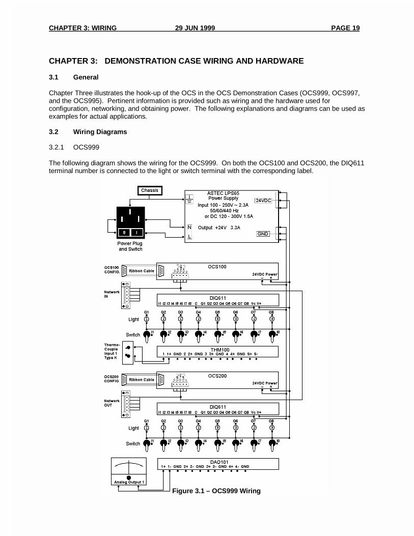
CHAPTER 3: DEMONSTRATION CASE WIRING AND HARDWARE
3.1 General
Chapter Three illustrates the hook-up of the OCS in the OCS Demonstration Cases (OCS999, OCS997,and the OCS995). Pertinent information is provided such as wiring and the hardware used forconfiguration, networking, and obtaining power. The following explanations and diagrams can be used asexamples for actual applications.
3.2 Wiring Diagrams
3.2.1 OCS999
The following diagram shows the wiring for the OCS999. On both the OCS100 and OCS200, the DIQ611terminal number is connected to the light or switch terminal with the corresponding label.
Figure 3.1 – OCS999 Wiring
PAGE 20 29 JUN 1999 CHAPTER 3: WIRING
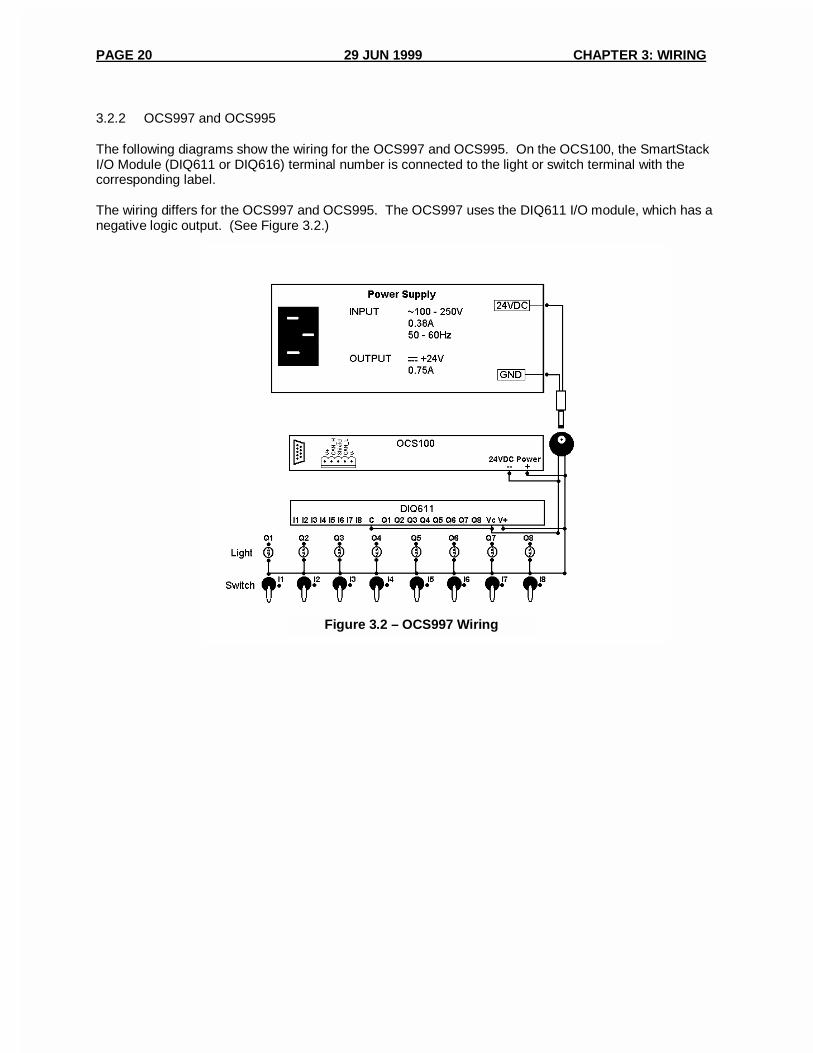
3.2.2 OCS997 and OCS995
The following diagrams show the wiring for the OCS997 and OCS995. On the OCS100, the SmartStackI/O Module (DIQ611 or DIQ616) terminal number is connected to the light or switch terminal with thecorresponding label.
The wiring differs for the OCS997 and OCS995. The OCS997 uses the DIQ611 I/O module, which has anegative logic output. (See Figure 3.2.)
Figure 3.2 – OCS997 Wiring

CHAPTER 3: WIRING 29 JUN 1999 PAGE 21
The OCS995 uses DIQ616 I/O module, which has a positive logic output. (See Figure 3.3.)
3.3 Configuration Port Connections
3.3.1 OCS999
The OCS999 Demo Case has two 9-pin configuration ports. One port is labeled “OCS100 CONFIG,” andthe other port is labeled “OCS200 CONFIG.” The OCS100 configuration port is connected with a ribboncable directly to the 9-pin config/debug port on the OCS100. The OCS200 configuration port isconnected with a ribbon cable directly to the 9-pin config/debug port on the OCS200.
Each OCS can be programmed from either port as long as the Cscape software is setup to communicatewith the correct node ID. This is made possible using the CsCAN network to connect the two OCS units.
To program or configure one of the OCS units using the Cscape software, use the included 9-pin cable toconnect the configuration port to a COM port on the user’s PC. Use the Cscape software to programladder logic and configure the OCS with I/O.
Note: The Cscape software must be setup to communicate with the same node ID as what theOCS unit node ID is setup for. The OCS unit node ID can be found by pressing the ‘System’button and then pressing ‘Enter’ on Set Network ID. Press ‘Esc’ twice to get back to thedemonstration program.
Figure 3.3 – OCS995 Wiring
PAGE 22 29 JUN 1999 CHAPTER 3: WIRING
3.3.2 OCS997 and OCS995
The OCS997 and OCS995 are not equipped with a front panel configuration port, but there is one on theback of the OCS100 that is contained in each case. It is labeled ‘CONFIG/DEBUG PORT’. To programor configure the OCS unit using the Cscape software, use the included 9-pin cable to connect theconfiguration port to a COM port on the user’s PC. Use the Cscape software to program ladder logic andconfigure the OCS with I/O.
Note: The Cscape software must be setup to communicate to the same node ID as what theOCS100 node ID is setup for. The OCS unit node ID can be found by pressing the ‘System’ button,then pressing ‘Enter’ on Set Network ID. Press ‘Esc’ twice to get back to the demonstrationprogram.
3.4 Network Connections
3.4.1 OCS999
The OCS999 Demo Case has two 5-pin Network connections. One pin is labeled ‘NETWORK IN’, andone pin is labeled ‘NETWORK OUT’. These ports come from the factory with terminator plugs installed.They have a 120Ω resistor located between the ‘CN_H’ and ‘CN_L’ terminals.
The ‘NETWORK IN’ connection is internally connected to the OCS100 Network connection and is daisy-chained around to the OCS200 Network connection, which is then daisy-chained to the ‘NETWORK OUT’connection
CsCAN is like most any other CAN in that it requires a 120Ω terminating resistance at each end of thenetwork. The OCS999 Demo Case comes with the resistors installed in the ‘NETWORK IN’ and‘NETWORK OUT’ connections, because those are the ends of this particular network.
If it is desired to connect nodes to the CsCAN, remove the terminating resistor plug and wire in thenetwork to either the ‘NETWORK IN’ or ‘NETWORK OUT’, or both.
Note When doing this, make sure a 120Ω terminating resistor is placed between CAN_H and CAN_L at the new ends of the network.
3.4.2 OCS997 and OCS995
The OCS997 and OCS995 do not have a front panel network connection, but there is one on the OCS100contained in each case. It is labeled ‘NETWORK’. No connection is necessary, and the demonstrationprogram will function as it is supposed to.
If it is desired to connect more nodes to the CsCAN, use the existing plug and wire in the network to the‘NETWORK’ port on the OCS100.
Note: When doing this, make sure a 120Ω terminating resistor is placed between CAN_H and CAN_L at the ends of the network.

CHAPTER 3: WIRING 29 JUN 1999 PAGE 23
3.5 Power Connections
3.5.1 OCS999
The OCS999 comes with a power supply mounted in the case that gets its input power from the plug andswitch mounted on the front panel. Use the included power cord to connect 100 – 250VAC at 50 – 60Hz.The power supply converts the input to 24VDC, which powers both the OCS100 and OCS200. This24VDC output is also the source of power for the DIQ611 modules.
3.5.2 OCS997 and OCS995
The OCS997 and the OCS995 come with a power supply that is not attached to the panel. Use theincluded power cord to connect 100 – 250VAC at 50 – 60Hz to the power supply and connect the powersupply cord to the power plug on the front panel. The power supply converts the input to 24VDC, whichpowers the OCS100. This 24VDC output is also the source of power for the SmartStack I/O Module.

PAGE 24 29 JUN 1999 CHAPTER 3: WIRING
NOTES