operator and parts manual - farm king · better stability at greater heights, ... large input and...
TRANSCRIPT

OperatOr and parts Manual
052012 FK325
Backsaver Auger13" Model

3
Table of Contents - 13" Backsaver Auger
Table of Contents
Introduction .................................................................................................................................5
Safety ............................................................................................................................................6• Safety ................................................................................................................................6• General Safety ..................................................................................................................7• Start-up Safety .................................................................................................................7• Operation Safety ..............................................................................................................7• Transport Safety ...............................................................................................................8• Service and Maintenance Safety ....................................................................................8• Storage Safety ..................................................................................................................9• Safety Signs .....................................................................................................................9• Safety Sign Installation ...................................................................................................9
Assembly ....................................................................................................................................12• Assembly Instructions ...................................................................................................12
Operation ...................................................................................................................................14• Theory of Operation ......................................................................................................18
Maintenance ..............................................................................................................................19• Maintenance and Lubricantion .....................................................................................19• Storage ...........................................................................................................................19• Greasing Procedure .......................................................................................................20
Bolt Torque .................................................................................................................................21• Checking Bolt Torque .....................................................................................................21
Parts Drawings ...........................................................................................................................22• Auger Assembly Drawing .............................................................................................22• Auger Assembly Parts List ............................................................................................23• Lift Boom Arm Components Drawing ..........................................................................26• Lift Boom Arm Components Parts List .........................................................................27• Intake Auger Drawing ....................................................................................................28• Intake Auger Parts List ...................................................................................................29• Hopper and Auger Assembly Drawing .........................................................................30• Hopper and Auger Assembly Parts List ........................................................................31• Input Box Assembly Drawing .......................................................................................32• Input Box Assembly Parts List ......................................................................................33• Intake Auger Assembly Drawing ..................................................................................36• Intake Auger Assembly Parts List .................................................................................37• Single Flighting Hopper Drawing .................................................................................38
4
• Single Flighting Hopper Parts List ................................................................................39• 13" x 10' Extension Drawing .........................................................................................40• 13" x 10' Extension Parts List ........................................................................................41• Double Flighting Hopper Drawing ................................................................................42• Double Flighting Hopper Parts List ...............................................................................43• Cables Drawing ..............................................................................................................46• Cables Parts List .............................................................................................................47• Idler Assembly Drawing ................................................................................................48• Idler Assembly Parts List ...............................................................................................49• Tire Assembly Drawing .................................................................................................50• Tire Assembly Parts List ................................................................................................51• Cylinder Mount Components Drawing ........................................................................52• Cylinder Mount Components Parts List .......................................................................53• Undercarriage Pivot Ring Drawing ...............................................................................53• Undercarriage Bridging Yoke Drawing .........................................................................53• Hydraulics Drawing .......................................................................................................56• Hydraulics Parts List ......................................................................................................57• 4.5 x 42.50 Cylinder Assembly Drawing and Parts List ...............................................58• 5.0 x 51.35 Cylinder Assembly Drawing and Parts List ...............................................59• 13" x 70' Reverse Option PTO Drawing ........................................................................60• 13" x 70' Reverse Option PTO Parts List .......................................................................61• 13" x 85' Reverse Option PTO Drawing ........................................................................62• 13" x 85' Reverse Option PTO Parts List .......................................................................63• IM1000 Gearbox Retrofit Drawing ................................................................................64• M1000 Gearbox Retrofit Parts List ................................................................................65• M1000 Gearbox 910927 Drawing ..................................................................................66• M1000 Gearbox 910927 Parts List .................................................................................67• Gearbox 911131 Drawing ...............................................................................................68• Gearbox 911131 Parts List ..............................................................................................69• Gearbox 960950 Drawing ..............................................................................................70• Gearbox 960950 Parts List .............................................................................................71• Gearbox 960788 Drawing ..............................................................................................72• Gearbox 960788 Parts List .............................................................................................72• Winch Drawing ...............................................................................................................74• Winch Parts List ..............................................................................................................75
Shipping Kit and Bundle Numbers ..........................................................................................76
Warranty .....................................................................................................................................82
Manufacturer’s statement: for technical reasons Buhler Industries Inc. reserves the right to modify machinery design and specifications provided herein without any preliminary notice. Information provided herein is of descriptive nature. Performance quality may depend on soil fertility, applied agricultural techniques, weather conditions and other factors.
Table of Contents - 13" Backsaver Auger

5
Introduction
Farm King gives you more choices to match your auger to your bins, power sources and operating convenience. The superior scissor lift system features a one way hydraulic cylinder with a restrictor valve to control the rate of descent in the event of hydraulic hose failure. This feature is safer than conventional cable systems. Also, note the extra wide undercarriage and wheel tread providing better stability at greater heights, particularly in windy conditions. This unique mechanical linkage is designed to use less hydraulic pressure to lift the auger, even when fully loaded. The pivoting Hopper Lift arm may be flipped over for left or right transport position. Slip the PTO from the main shaft onto the optional reverse kit for complete cleanout. An adjustable arm holds the PTO shaft when not in use. The hitch is adjustable for various tractor hitch lengths. The shut off valve is designed to keep your auger in the position you set it. The cross auger and main auger are driven by two internal gearboxes, easily reached for service. Because of the large input and intake boxes, capacity is not restricted. The standard self leveling hopper on all Back Saver augers stays flat on the ground, even when the auger is raised up to a high bin. The optional double auger hopper is 2.5" lower than the standard self-leveling hopper. An optional 2 wheel power mover allows you to move the hopper back and forth with finger tip control. Other advanced features include a tapered thrust bearing at the top of the auger, torqued to remove pressure on the bottom end bearing. Keep this manual handy for frequent reference. All new operators or owners must review the manual before using the equipment and at least annually thereafter. Contact your Farm King Dealer if you need assistance, information, or additional copies of the manual. Visit our website at www.buhlerindustries.com for a complete list of dealers in your area. The directions left, right, front and rear, as mentioned throughout this manual, are as seen facing in the direction of travel of the implement.
Introduction - 13" Backsaver Auger

6
Safety
Safety InstructionsRemember, YOU are the key to safety. Good safety practices not only protect you, but also the people around you. Make these practices a working part of your safety program. Be certain that everyone operating this equipment is familiar with the recommended operating and maintenance procedures and follows all the safety precautions. Most accidents can be prevented. Do not risk injury or death by ignoring good safety practices.
The alert symbol is used throughout this manual. It indicates attention is required and identifies hazards. Follow the recommended precautions.
The safety alert symbol means… ATTENTION! BECOME ALERT! YOUR SAFETY IS INVOLVED!
CAUTIONThe caution symbol indicates a potentially hazardous situation that, if not avoided, may result in minor or moderate injury. It may also be used to alert against unsafe practices.
WARNINGThe Warning Symbol indicates a potentially hazardous situation that, if not avoided, could result in death or serious injury, and includes hazards that are exposed when guards are removed. It may also be used to alert against unsafe practices.
DANGER
The Danger Symbol indicates an imminently hazardous situation that, if not avoided will result in death or serious injury. This signal word is to be limited to the most extreme situations, typically for machine components that, for functional purposes, cannot be guarded.
Safety - 13" Backsaver Auger

7
General Safety Instructions• Have a first-aid kit available for use and know how to use it. • Have a fire extinguisher available, stored in a highly visible location, and know how to use it.• Wear appropriate protective gear. This list may include but is not limited to:
- hard hat - protective shoes with slip resistant soles - protective glasses or goggles - heavy gloves - wet weather gear - hearing protection - respirator or filter mask
• Read and understand the Operator’s Manual and all safety signs before operating, servicing, adjusting, repairing, or unplugging the equipment.
• Do not attempt any unauthorized modifications to your Farm King product as this could affect function or safety, and could affect the life of the equipment.
• Never start or operate the mower except from the operator’s station on the power unit.• Inspect and clean the working area before operating. • Keep hands, feet, clothing, and hair away from moving parts. • Ensure bystanders are clear of the area before operating.
Start-up Safety• Do not let inexperienced operators or children run this equipment.• Place all tractor and machine controls in neutral before starting.• Operate only with ROPS and seatbelt equipped tractors.• Do not operate inside a building unless there is adequate ventilation.• Ensure all shields are in place and in good condition before operating.• Stay clear of PTO shaft and machine when engaging PTO.• The Auger must be on a level surface and wheels free to move when raising or lowering.
Everyone should be kept clear during these operations.
Operation Safety• Do not permit riders.• Do not wear loose fitting clothing during operation.• Empty the Auger before moving to prevent upending.• The Backsaver Auger should be attached to the drawbar of the tractor at all times during
operations.• Do not allow anyone other than the operator close to the Auger when in operation.• Never stand under the auger while raising or lowering.• When filling tall bins, tanks, or granaries, it is advisable to anchor the auger to the bin or
building to prevent it from being tipped over by the wind or a sudden movement.• Do not operate Intake Auger when it is folded in transport position.• Never raise the intake end end of the auger above waist high, as the balance shifts forward,
and the auger will tip over.• Stay away from overhead obstructions and power lines during operation and transporting.
Electrocution can occur without direct contact.
Safety - 13" Backsaver Auger
8
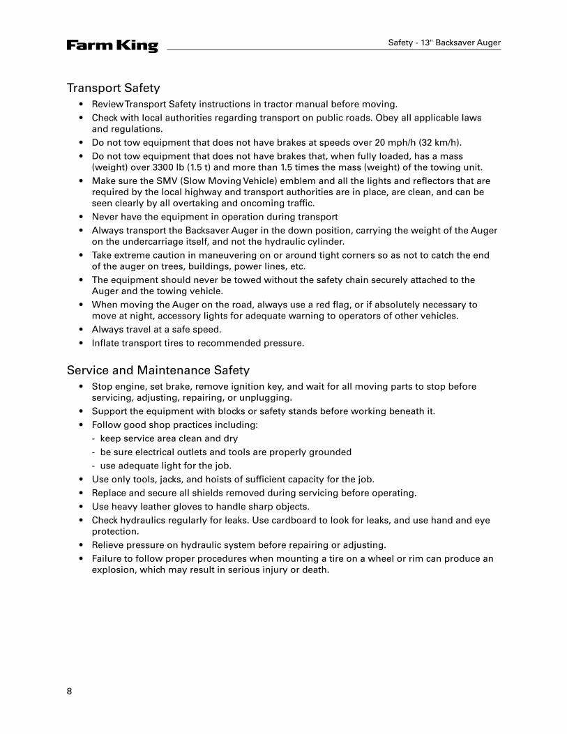
Transport Safety• Review Transport Safety instructions in tractor manual before moving.• Check with local authorities regarding transport on public roads. Obey all applicable laws
and regulations.• Do not tow equipment that does not have brakes at speeds over 20 mph/h (32 km/h).• Do not tow equipment that does not have brakes that, when fully loaded, has a mass
(weight) over 3300 lb (1.5 t) and more than 1.5 times the mass (weight) of the towing unit.• Make sure the SMV (Slow Moving Vehicle) emblem and all the lights and reflectors that are
required by the local highway and transport authorities are in place, are clean, and can be seen clearly by all overtaking and oncoming traffic.
• Never have the equipment in operation during transport• Always transport the Backsaver Auger in the down position, carrying the weight of the Auger
on the undercarriage itself, and not the hydraulic cylinder.• Take extreme caution in maneuvering on or around tight corners so as not to catch the end
of the auger on trees, buildings, power lines, etc.• The equipment should never be towed without the safety chain securely attached to the
Auger and the towing vehicle.• When moving the Auger on the road, always use a red flag, or if absolutely necessary to
move at night, accessory lights for adequate warning to operators of other vehicles.• Always travel at a safe speed.• Inflate transport tires to recommended pressure.
Service and Maintenance Safety• Stop engine, set brake, remove ignition key, and wait for all moving parts to stop before
servicing, adjusting, repairing, or unplugging.• Support the equipment with blocks or safety stands before working beneath it.• Follow good shop practices including:
- keep service area clean and dry - be sure electrical outlets and tools are properly grounded - use adequate light for the job.
• Use only tools, jacks, and hoists of sufficient capacity for the job.• Replace and secure all shields removed during servicing before operating.• Use heavy leather gloves to handle sharp objects.• Check hydraulics regularly for leaks. Use cardboard to look for leaks, and use hand and eye
protection.• Relieve pressure on hydraulic system before repairing or adjusting.• Failure to follow proper procedures when mounting a tire on a wheel or rim can produce an
explosion, which may result in serious injury or death.
Safety - 13" Backsaver Auger
9
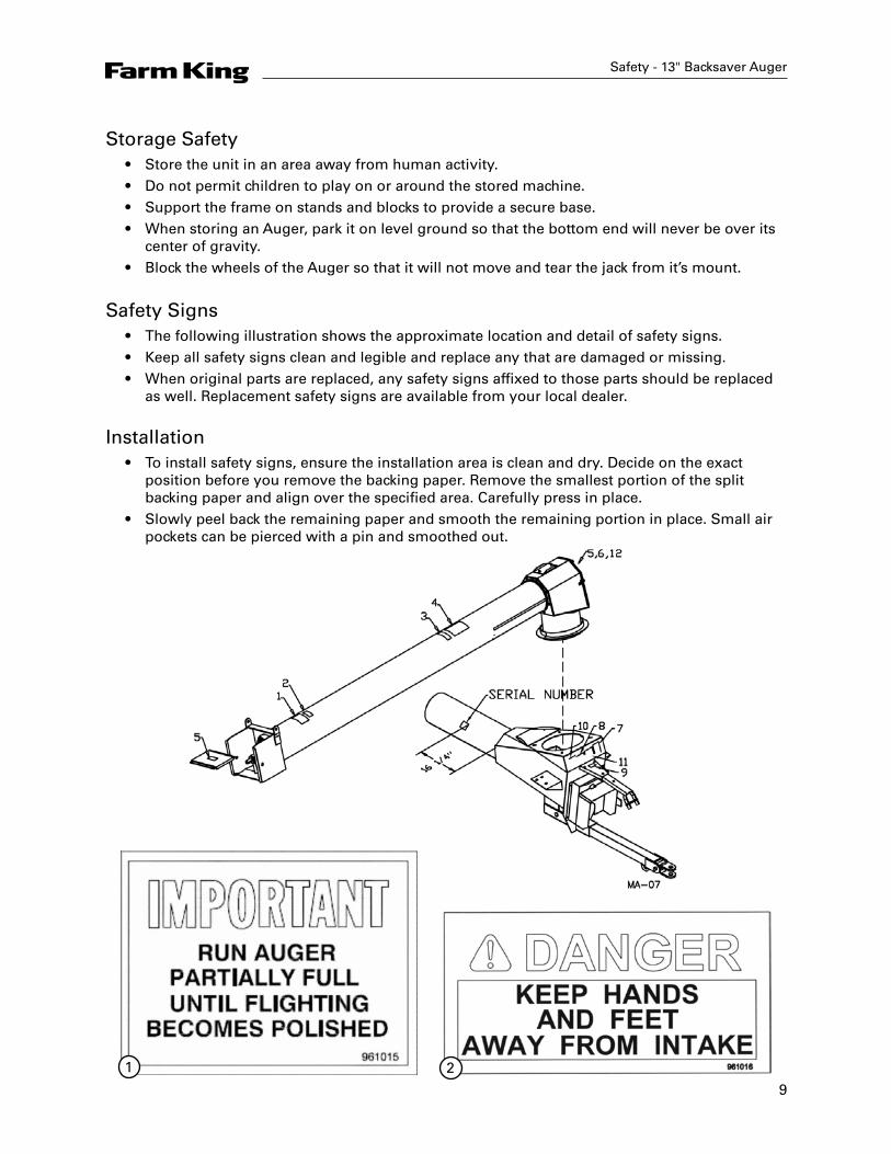
Storage Safety• Store the unit in an area away from human activity.• Do not permit children to play on or around the stored machine.• Support the frame on stands and blocks to provide a secure base.• When storing an Auger, park it on level ground so that the bottom end will never be over its
center of gravity.• Block the wheels of the Auger so that it will not move and tear the jack from it’s mount.
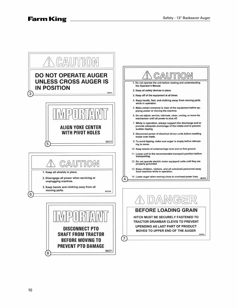
Safety Signs• The following illustration shows the approximate location and detail of safety signs.• Keep all safety signs clean and legible and replace any that are damaged or missing.• When original parts are replaced, any safety signs affixed to those parts should be replaced
as well. Replacement safety signs are available from your local dealer.
Installation• To install safety signs, ensure the installation area is clean and dry. Decide on the exact
position before you remove the backing paper. Remove the smallest portion of the split backing paper and align over the specified area. Carefully press in place.
• Slowly peel back the remaining paper and smooth the remaining portion in place. Small air pockets can be pierced with a pin and smoothed out.
Safety - 13" Backsaver Auger
1 2
10
Safety - 13" Backsaver Auger
3
4
5
6
7
8

11
Safety - 13" Backsaver Auger
9
10
11
12
12
Assembly Instructions
ALERT
There are two holes on the top stub shaft for cotter pin installation on the top flighting, which should allow a wide range of adjustment. If the top flighting is too high, there could be a shortage of room to mount the collar on the bottom bearing in the input box.
ALERTThe 13" x 85' auger has two positions to bolt on the main bridging yoke. The 85' auger uses the lower position. The upper position is only used when adding a 10-foot extension to make a 95' auger. Refer to the drawing included in this manual.
ALERTOn bridging yokes where the cable clamps hold two cables, DO NOT use the cast part of the cable clamp or it will be very difficult to get the nuts on the clamp.
ALERT Cylinder ports face down.
ALERT
The flow control valve regulates the lowering of the auger to avoid damge which could be caused by lowering the auger too quickly. Arrow should be pointing away from the cylinder. Be sure that the valve is open and approximately 3-1/2 turns before raising to full position or auger will not lower.
ALERTIf the intake auger is removed for repair or replacement, the bolt coupling the flighting to the intake auger gearbox must be replaced when the flighting is replaced. Not replacing this bolt could cause failure of the hopper flighting.
ALERT
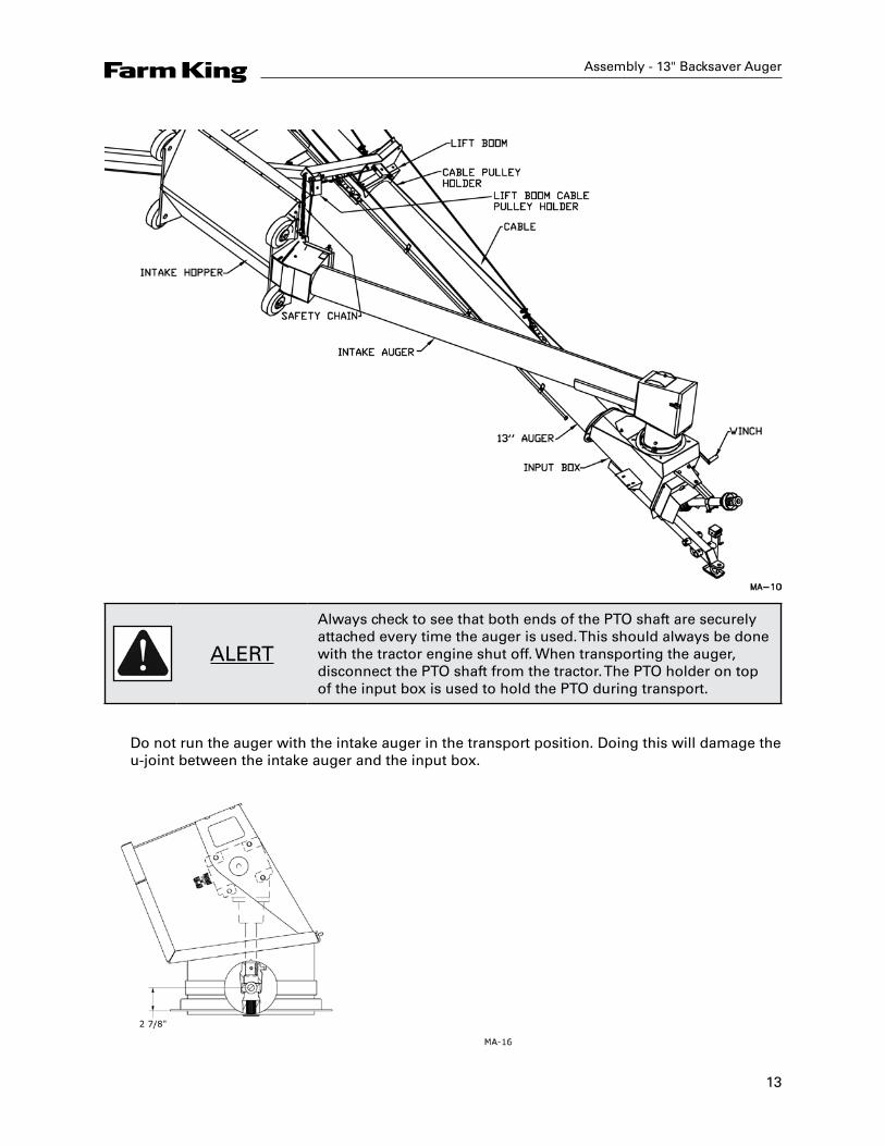
When the intake auger is raised in transport position, the lift cable is hooked into the loop at the bottom of the intake auger. The open end of the hook must be turned towards hopper. The intake auger could detach and fall if the main auger is raised with the hook turned the other way. See diagram on next page.
Assembly - 13" Backsaver Auger
13
Assembly - 13" Backsaver Auger
ALERT
Always check to see that both ends of the PTO shaft are securely attached every time the auger is used. This should always be done with the tractor engine shut off. When transporting the auger, disconnect the PTO shaft from the tractor. The PTO holder on top of the input box is used to hold the PTO during transport.
Do not run the auger with the intake auger in the transport position. Doing this will damage the u-joint between the intake auger and the input box.
14
Operation - 13" Backsaver Auger
Operation Instructions
• All augers may be elevated up to 45°; however, for the best operating efficiency, 35° should not be exceeded. At angles over 35° the capacity and life of the auger decreases. Use in some types of fertilizer may cause accelerated wear and corrosion as well as added stress on lift components due to additional load. Use in fertilizer can affect warranty.
• Run auger partially full until flighting becomes polished.• Never operate an empty auger for over one minute, as the flighting and housing will
experience excessive wear.• To position the auger, always tow or move the auger in the down position to a point as close
as possible to the bin or barn.
ALERTAlways keep the wheels level. Raise the auger to the desired height and back the auger into position. Do not support the auger on the bin. As the auger becomes full it carries alot of weight and may cause damage to the underside of the auger to the bin.
ALERT Never place blocks under the wheels to increase the elevation of auger.
• Be sure the wheels are free to move and no one is standing close to the auger when raising or lowering. Never attempt to raise or lower the auger while it is in operation.
ALERTBe sure winch brake is working properly before transporting. An arrow on the winch shows the proper direction of rotation. Improper rotation may cause winch failure. Never have less than three wraps of cable on the drum of the winch.
• The intake auger swivels freely on the top of the input box. It can be positioned anywhere between the tractor and the side of the auger.
ALERT13" augers are designed for PTO drive tractors with 540 PTO rpm only. Maximum capacity will be attained while running the main auger between 450-500 PTO rpm. Use 1000 rpm speed on these augers. Only with F1078 Retrofit Kit.
15
Operation - 13" Backsaver Auger
ALERT
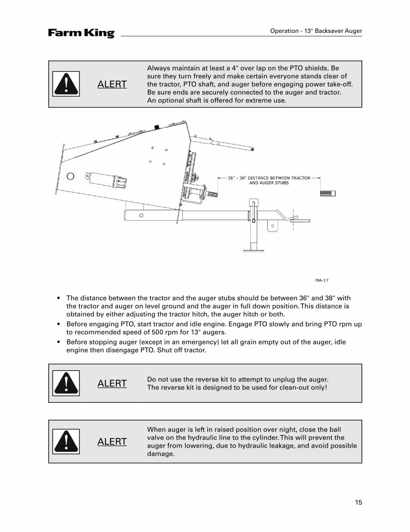
Always maintain at least a 4" over lap on the PTO shields. Be sure they turn freely and make certain everyone stands clear of the tractor, PTO shaft, and auger before engaging power take-off. Be sure ends are securely connected to the auger and tractor. An optional shaft is offered for extreme use.
• The distance between the tractor and the auger stubs should be between 36" and 38" with the tractor and auger on level ground and the auger in full down position. This distance is obtained by either adjusting the tractor hitch, the auger hitch or both.
• Before engaging PTO, start tractor and idle engine. Engage PTO slowly and bring PTO rpm up to recommended speed of 500 rpm for 13" augers.
• Before stopping auger (except in an emergency) let all grain empty out of the auger, idle engine then disengage PTO. Shut off tractor.
ALERT Do not use the reverse kit to attempt to unplug the auger. The reverse kit is designed to be used for clean-out only!
ALERTWhen auger is left in raised position over night, close the ball valve on the hydraulic line to the cylinder. This will prevent the auger from lowering, due to hydraulic leakage, and avoid possible damage.
16
• One way flow control valve can be adjusted by loosening the hex nut on the side, and turning on the screw with the machined end. Turning the screw in decreases the speed the auger lowers, while turning it out increases the speed. For the 13" x 70' auger, the approximate initial setting should be three turns out from the tight position. For the 13" x 85' auger, the approximate initial setting should be five turns out from the tight position. When set, re-tighten hex nut to set position. NOTE: Be sure that the valve is somewhat open before raising the first time or auger will not lower.
• Be sure there is always some tension on the flighting by adjusting the end thrust bearing at the upper end of the auger.
ALERTAlways lower auger before transporting and allow the weight of the auger to rest on the undercarriage and not the hydraulic cylinder.
• Be certain to turn jack sideways when towing auger.
ALERTDisconnect the PTO shaft from the tractor and pin it in place in the PTO holder when towing or maneuvering the auger. This will prevent possible damage to the PTO shaft during cornering.
ALERTIf the PTO shaft angle exceeds 50° during a tight turn, the constant velocity joints will be fractured and will likely failshortly thereafter during operation.
ALERT When towing the auger, never exceed 32 km/h (20 mph).
• Always use a flag, or at night, a signal light when towing an auger on a road. Check your local regulations for further safety devices in this regard.
Operation - 13" Backsaver Auger
17
Operation - 13" Backsaver Auger
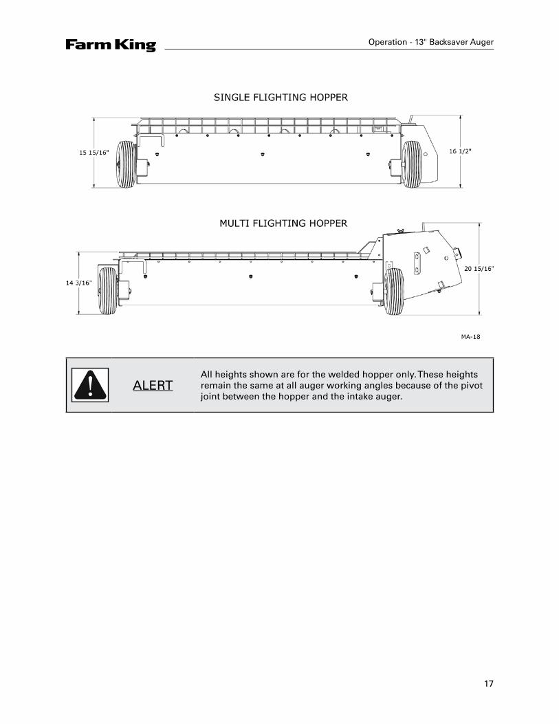
ALERTAll heights shown are for the welded hopper only. These heights remain the same at all auger working angles because of the pivot joint between the hopper and the intake auger.
18
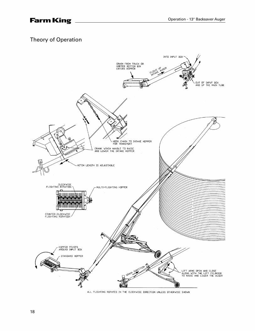
Theory of Operation
Operation - 13" Backsaver Auger

19
Maintenance - 13" Backsaver Auger
Maintenance
Maintenance and Lubrication• Check condition of winch cable occasionally. Be sure it is lubricated. Replace cable if you
notice any broken strands.• Check to see that there is no downward bow in the main tubes at the start of every augering
season. Re-tension cables if required as per step number four in the assembly instructions.This should also be checked immediately after hauling the auger for a long distance.
• Use a high temperature grease for all lubrication.• Lubricate the PTO shaft as per instruction sheet.• Check grease on end thrust bearing to be sure it is running smoothly and freely. Remove cap
and grease at the start of every season.• Check hydraulic lines frequently for leaks or damage.• Grease u-joint in intake auger after 8 hours of use.• Grease the u-joint connecting the two gearboxes about every 8 hours. Do regular checks on
the oil level in the gearboxes. Fill if necessary to the height of the side plug using SAE 90 oil. Because the gearbox runs in the grain, it is difficult to see any oil leaks so regular checks should be done.
ALERTWhen replacing bearings or tightening a loose bearing collar, always tighten collar in the direction of shaft rotation using a center punch or a similar tool.
• Recommended tire pressure is 50 psi.
Storage• The auger should be stored in a dry place if possible. If stored outside, lower auger to its
lowest position and block up the wheels so auger will not move.• Clean auger thoroughly as dirt draws moisture and causes metal to rust. If the auger has
been used to move fertilizer, clean thoroughly and apply oil or grease on entire flighting and inside the housing to stop and prevent further corrosion.
• At this time check all moving parts for wear and order replacement parts from your nearest dealer.
• When taking the auger out of storage, clean it thoroughly and check for obstructions at the inlet and outlet ends.
• Check all bolts and set screws.
20
• Regularly check the tightness of all cable clamps to avoid slipping. Inspect wire rope regularly for evidence of wear or corrosion. Such inspections should take place at progressively shorter intervals over the useful life of the rope, as wear tends to accelerate with use and/or age. Where wear is rapid, the outside of a wire rope will show flattened surfaces in a short time. A piece of cloth or rag, rubbed along the wire rope will help to reveal broken wires. The effects of corrosion are not easy to detect because the exterior wires may appear to be only slightly rusty, and the damaging effects of corrosion may be confined to the hidden inner wires where it cannot be seen. To prevent damage by corrosion, the rope should be kept well lubricated. Periodic cleaning of wire rope by using a stiff brush and kerosene or with compressed air or live steam and relubricating will help to lengthen rope life and reduce abrasion and wear on sheaves and drums.
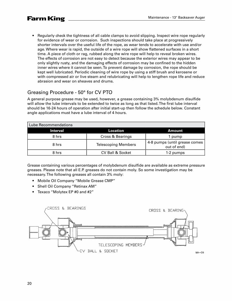
Greasing Procedure - 50° for CV PTOA general purpose grease may be used, however, a grease containing 3% molybdenum disulfide will allow the lube intervals to be extended to twice as long as that listed. The first lube interval should be 16-24 hours of operation after initial start-up then follow the schedule below. Constant angle applications must have a lube interval of 4 hours.
Lube Recommendations
Interval Location Amount
8 hrs Cross & Bearings 1 pump
8 hrs Telescoping Members4-8 pumps (until grease comes
out of end)
8 hrs CV Ball & Socket 1-2 pumps
Grease containing various percentages of molybdenum disulfide are available as extreme pressure greases. Please note that all E.P. greases do not contain moly. So some investigation may be necessary. The following greases all contain 3% moly:
• Mobile Oil Company “Mobile Grease CMP”• Shell Oil Company “Retinax AM”• Texaco “Molytex EP #0 and #2”
Maintenance - 13" Backsaver Auger
21
Bolt Torque - 13" Backsaver Auger
Bolt Torque
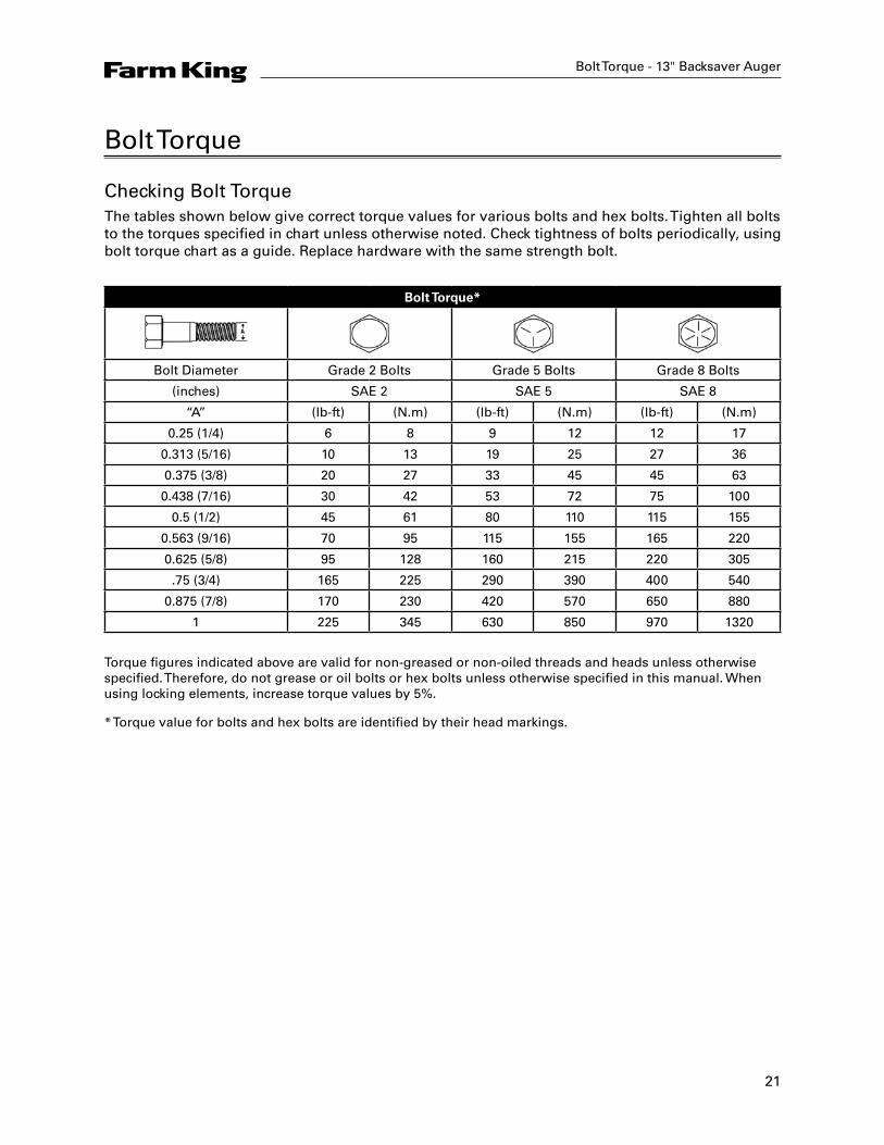
Checking Bolt TorqueThe tables shown below give correct torque values for various bolts and hex bolts. Tighten all bolts to the torques specified in chart unless otherwise noted. Check tightness of bolts periodically, using bolt torque chart as a guide. Replace hardware with the same strength bolt.
Bolt Torque*
Bolt Diameter Grade 2 Bolts Grade 5 Bolts Grade 8 Bolts
(inches) SAE 2 SAE 5 SAE 8
“A” (lb-ft) (N.m) (lb-ft) (N.m) (lb-ft) (N.m)
0.25 (1/4) 6 8 9 12 12 17
0.313 (5/16) 10 13 19 25 27 36
0.375 (3/8) 20 27 33 45 45 63
0.438 (7/16) 30 42 53 72 75 100
0.5 (1/2) 45 61 80 110 115 155
0.563 (9/16) 70 95 115 155 165 220
0.625 (5/8) 95 128 160 215 220 305
.75 (3/4) 165 225 290 390 400 540
0.875 (7/8) 170 230 420 570 650 880
1 225 345 630 850 970 1320
Torque figures indicated above are valid for non-greased or non-oiled threads and heads unless otherwise specified. Therefore, do not grease or oil bolts or hex bolts unless otherwise specified in this manual. When using locking elements, increase torque values by 5%.
* Torque value for bolts and hex bolts are identified by their head markings.

22
Parts - 13" Backsaver Auger
Auger Assembly Drawing
23
Parts - 13" Backsaver Auger
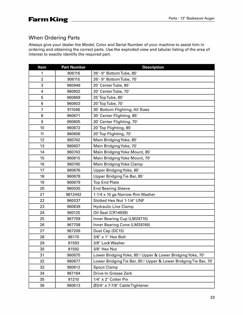
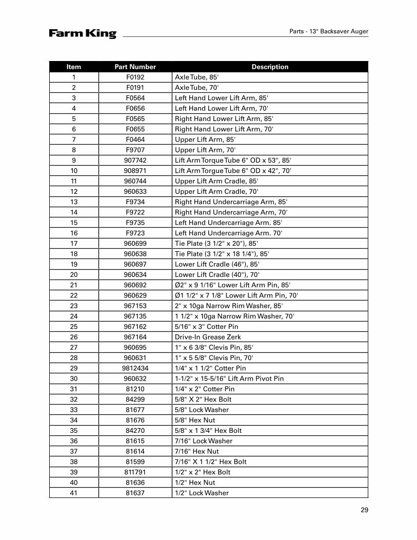
When Ordering PartsAlways give your dealer the Model, Color and Serial Number of your machine to assist him in ordering and obtaining the correct parts. Use the exploded view and tabular listing of the area of interest to exactly identify the required part.
Item Part Number Description
1 906116 26'- 9" Bottom Tube, 85'
2 906115 26'- 9" Bottom Tube, 70'
3 960949 20' Center Tube, 85'
4 960602 20' Center Tube, 70'
5 960669 25' Top Tube, 85'
6 960603 20' Top Tube, 70'
7 911048 30' Bottom Flighting, All Sizes
8 960671 30' Center Flighting, 85'
9 960605 30' Center Flighting, 70'
10 960672 20' Top Flighting, 85'
11 960606 20' Top Flighting, 70'
12 960742 Main Bridging Yoke, 85'
13 960607 Main Bridging Yoke, 70'
14 960743 Main Bridging Yoke Mount, 85'
15 960615 Main Bridging Yoke Mount, 70'
16 960745 Main Bridging Yoke Clamp
17 960676 Upper Bridging Yoke, 85'
18 960678 Upper Bridging Tie Bar, 85'
19 960679 Top End Plate
20 960035 End Bearing Sleeve
21 9812442 1-1/4 x 10 ga Narrow Rim Washer
22 960037 Slotted Hex Nut 1-1/4" UNF
23 960639 Hydraulic Line Clamp
24 960125 Oil Seal (CR14939)
25 967709 Inner Bearing Cup (LM29710)
26 967708 Inner Bearing Cone (LM29749)
27 967209 Dust Cap (DC15)
28 86170 3/8" x 1" Hex Bolt
29 81593 3/8" Lock Washer
30 81592 3/8" Hex Nut
31 960675 Lower Bridging Yoke, 85'/ Upper & Lower Bridging Yoke, 70'
32 960677 Lower Bridging Tie Bar, 85'/ Upper & Lower Bridging Tie Bar, 70'
33 960612 Spout Clamp
34 967164 Drive-In Grease Zerk
35 81210 1/4" x 2" Cotter Pin
36 960613 Ø3/4" x 7-7/8" Cable Tightener
24
Parts - 13" Backsaver Auger
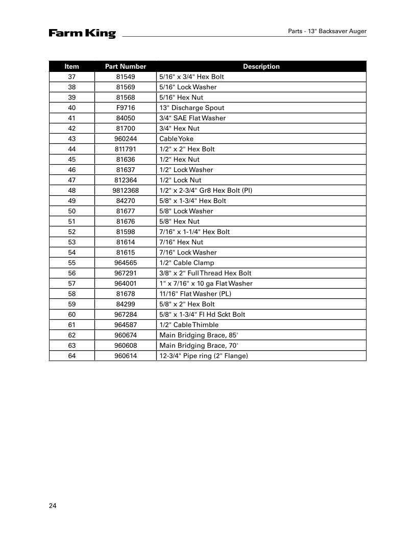
Item Part Number Description
37 81549 5/16" x 3/4" Hex Bolt
38 81569 5/16" Lock Washer
39 81568 5/16" Hex Nut
40 F9716 13" Discharge Spout
41 84050 3/4" SAE Flat Washer
42 81700 3/4" Hex Nut
43 960244 Cable Yoke
44 811791 1/2" x 2" Hex Bolt
45 81636 1/2" Hex Nut
46 81637 1/2" Lock Washer
47 812364 1/2" Lock Nut
48 9812368 1/2" x 2-3/4" Gr8 Hex Bolt (Pl)
49 84270 5/8" x 1-3/4" Hex Bolt
50 81677 5/8" Lock Washer
51 81676 5/8" Hex Nut
52 81598 7/16" x 1-1/4" Hex Bolt
53 81614 7/16" Hex Nut
54 81615 7/16" Lock Washer
55 964565 1/2" Cable Clamp
56 967291 3/8" x 2" Full Thread Hex Bolt
57 964001 1" x 7/16" x 10 ga Flat Washer
58 81678 11/16" Flat Washer (PL)
59 84299 5/8" x 2" Hex Bolt
60 967284 5/8" x 1-3/4" Fl Hd Sckt Bolt
61 964587 1/2" Cable Thimble
62 960674 Main Bridging Brace, 85'
63 960608 Main Bridging Brace, 70'
64 960614 12-3/4" Pipe ring (2" Flange)

26
Parts - 13" Backsaver Auger
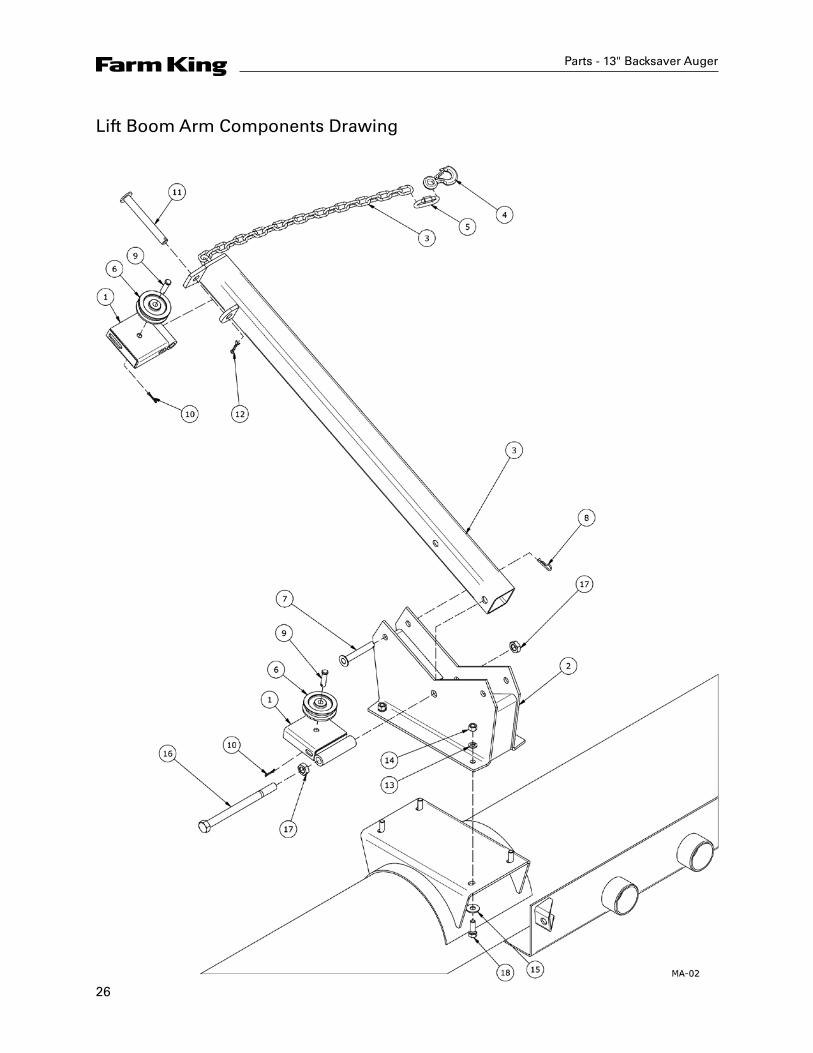
Lift Boom Arm Components Drawing
27
Parts - 13" Backsaver Auger
Item Part Number Description
1 905602 Pulley Holder
2 905601 Lift Boom
3 905604 Lift Boom Arm
4 960041 Hook w/ Latch
5 960167 5/16" Quick Link
6 961846 Cable Pulley, 1/2 Bore
7 905568 Pin 5/8" x 4-1/4"
8 961012 #16 Hair Pin Clip
9 960913 1/2" x 1-13/16" Clevis Pin
10 9812430 1/8" x 1" Cotter Pin
11 905570 3/4" x 6-3/8" Pin
12 9812433 3/16" x 1-1/2" Cotter Pin
13 81637 1/2" Lock Washer
14 81636 1/2" Hex Nut
15 81638 1/2" Flat Washer
16 811803 3/4" x 10" Hex Bolt
17 86111 3/4" Jam Hex Nut
18 84277 1/2" x 1-1/2" Hex Bolt
28
Parts - 13" Backsaver Auger
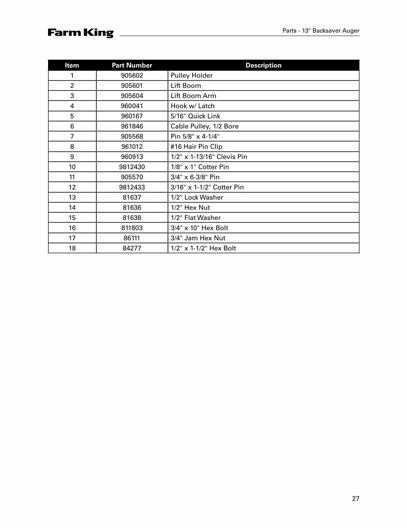
Intake Auger Drawing
29
Parts - 13" Backsaver Auger
Item Part Number Description
1 F0192 Axle Tube, 85'
2 F0191 Axle Tube, 70'
3 F0564 Left Hand Lower Lift Arm, 85'
4 F0656 Left Hand Lower Lift Arm, 70'
5 F0565 Right Hand Lower Lift Arm, 85'
6 F0655 Right Hand Lower Lift Arm, 70'
7 F0464 Upper Lift Arm, 85'
8 F9707 Upper Lift Arm, 70'
9 907742 Lift Arm Torque Tube 6" OD x 53", 85'
10 908971 Lift Arm Torgue Tube 6" OD x 42", 70'
11 960744 Upper Lift Arm Cradle, 85'
12 960633 Upper Lift Arm Cradle, 70'
13 F9734 Right Hand Undercarriage Arm, 85'
14 F9722 Right Hand Undercarriage Arm, 70'
15 F9735 Left Hand Undercarriage Arm. 85'
16 F9723 Left Hand Undercarriage Arm. 70'
17 960699 Tie Plate (3 1/2" x 20"), 85'
18 960638 Tie Plate (3 1/2" x 18 1/4"), 85'
19 960697 Lower Lift Cradle (46"), 85'
20 960634 Lower Lift Cradle (40"), 70'
21 960692 Ø2" x 9 1/16" Lower Lift Arm Pin, 85'
22 960629 Ø1 1/2" x 7 1/8" Lower Lift Arm Pin, 70'
23 967153 2" x 10ga Narrow Rim Washer, 85'
24 967135 1 1/2" x 10ga Narrow Rim Washer, 70'
25 967162 5/16" x 3" Cotter Pin
26 967164 Drive-In Grease Zerk
27 960695 1" x 6 3/8" Clevis Pin, 85'
28 960631 1" x 5 5/8" Clevis Pin, 70'
29 9812434 1/4" x 1 1/2" Cotter Pin
30 960632 1-1/2" x 15-5/16" Lift Arm Pivot Pin
31 81210 1/4" x 2" Cotter Pin
32 84299 5/8" X 2" Hex Bolt
33 81677 5/8" Lock Washer
34 81676 5/8" Hex Nut
35 84270 5/8" x 1 3/4" Hex Bolt
36 81615 7/16" Lock Washer
37 81614 7/16" Hex Nut
38 81599 7/16" X 1 1/2" Hex Bolt
39 811791 1/2" x 2" Hex Bolt
40 81636 1/2" Hex Nut
41 81637 1/2" Lock Washer
30
Parts - 13" Backsaver Auger
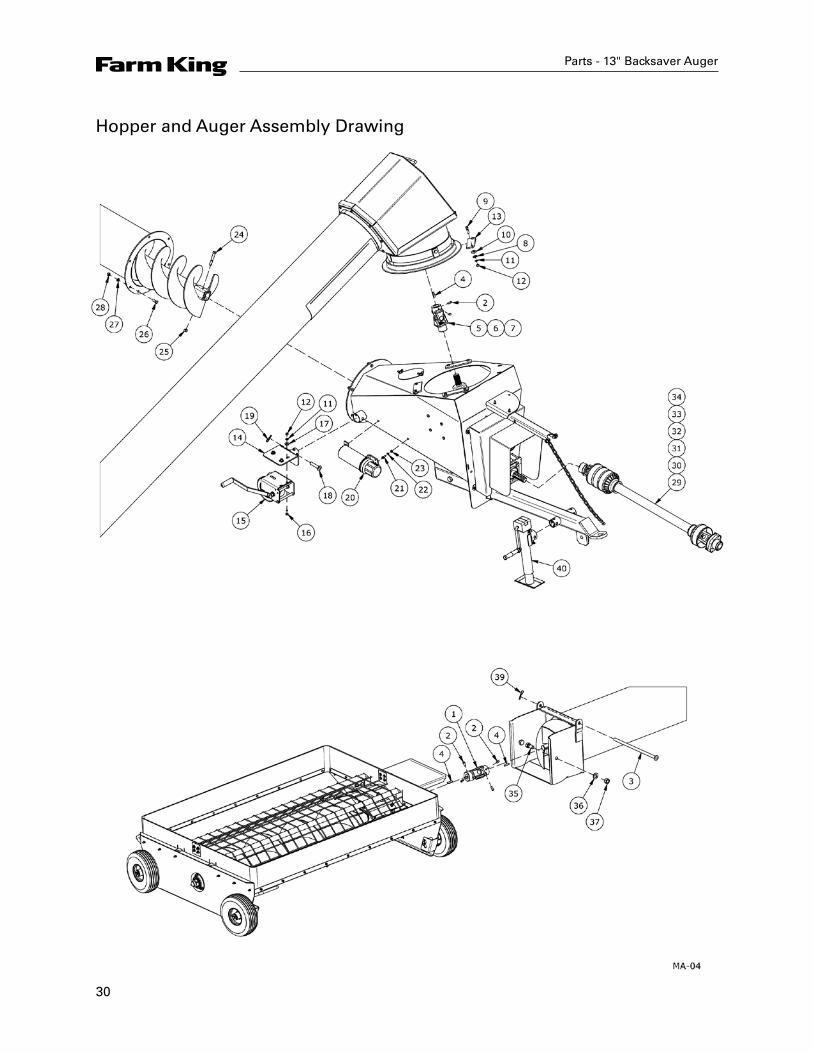
Hopper and Auger Assembly Drawing
31
Parts - 13" Backsaver Auger
Item Part Number Description
1 960547 Universal Joint (1140 Series) 1-1/4" Ends w/ 5/16" Keyway
2 9812378 3/8" x 3/4" Square Head Set Screw (Ser)
3 960356 Pivot Hopper Lid Rod
4 960180 5/16" x 1-3/8 " U-Joint & Sprocket Key
5 960784 U-Joint (Ø1 3/8"ID)
6 906547 Repair Kit Extended Life (Standard)
7 936079 Repair Kit (Optional)
8 964001 1" x 7/16" x 10 ga Flat Washer
9 811792 3/8" x 1-1/2" Hex Bolt
10 960494 13/32" x 1-1/4"OD Flat Washer
11 81593 3/8" Lock Washer
12 81592 3/8" Hex Nut
13 960653 Ring Clamp
14 911000 Winch Mount
15 961888 Winch (Fulton - K1550)
16 86170 3/8" x 1" Hex Bolt
17 84000 7/16" Flat Washer
18 902486 Skid Pin 5/8" x 3-1/8"
19 961012 #16 Hair Pin Clip
20 909277 Manual Holder
21 81549 5/16" x 3/4" Hex Bolt
22 81569 5/16" Lock Washer
23 81568 5/16" Hex Nut
24 81628 1/2" x 3-1/4" Hex Bolt (Pl)
25 812364 1/2" Lock Nut
26 81598 7/16" x 1-1/4" Hex Bolt
27 81615 7/16" Lock Washer
28 81614 7/16" Hex Nut
29 F0608 PTO Shaft CV 55R Ser (2-6 Spline), 85'
30 908721 Tractor Half PTO, CV 55R Ser (6 Spline), 85'
31 908722 Auger Half PTO, 55R Ser (6 Spline), 85'
32 F9552 PTO Shaft CV (2-6 Spline), 70'
33 936566 Tractor Half PTO, CV (6 Spline), 70'
34 908720 Auger Half PTO, (6 Spline), 70'
35 967437 3/4" x 1-5/8" Hex Bolt
36 84050 3/4" SAE Flat Washer
37 812365 3/4" Lock Nut
38 81678 11/16" Flat Washer (PL)
39 12780 #7 Hair Pin Clip
40 905066 Jack Side Crank
32
Parts - 13" Backsaver Auger
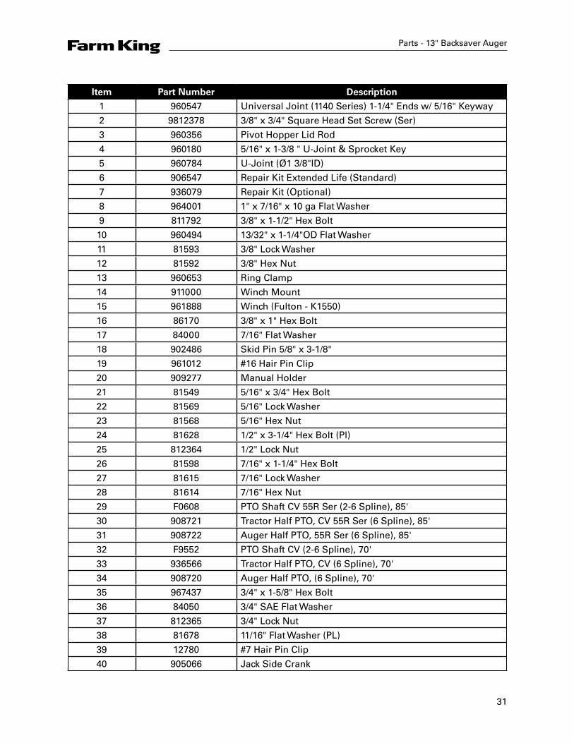
Input Box Assembly Drawing

33
Parts - 13" Backsaver Auger
Item Part Number Description
1 910985 Input Box
2 960788 4168 Gearbox
3 911396 3" Square x 51" Hitch (Option)
4 911395 3" Square x 54" Hitch Tube
5 960927 Clevis (Option - Required w/ Hitch Option)
6 911148 Guard
7 911141 Reinforcement Bracket
8 911111 PTO Holder Arm
9 909703 PTO Holder Chain Assembly
10 910892 Lid
11 911020 Clean-Out Lid
12 910991 Drive Shaft (Chain Drive)
13 910989 #80 Chain - 36 Links
14 910992 Gearbox Mounting Plate (Outside)
15 910994 Gearbox Mounting Plate (Inside)
16 910287 Safety Chain (1/4") G70
17 960041 Hook with Latch
18 960167 5/16" Quick Link
19 960719 80B15 Sprocket (1.5" Bore)
20 961041 80B15 Sprocket (1.375" Bore)
21 81620 1/2" x 1-1/4" Hex Bolt
22 81637 1/2" Lock Washer
23 81549 5/16" x 3/4" Hex Bolt
24 81569 5/16" Lock Washer
25 961675 Bearing Flange 72MS
26 965917 1-3/8" Bearing
27 86170 3/8" x 1" Hex Bolt
28 81593 3/8" Lock Washer
29 81592 3/8" Hex Nut
30 960180 5/16" x 1-3/8 " U-Joint & Sprocket Key
31 988999 3/8" x 3/8" Socket Set Screw
32 84217 3/8" Wing Nut
33 968601 5/16" Wing Nut
34 811790 3/4" x 4 /12" Grade 5 Hex Bolt
35 812365 3/4" Lock Nut
36 968627 Bearing with Collar Ø1-1/2" ID (AEL208-108)
37 902395 Bearing Flange (80mm - 4sq.)
38 81568 5/16" Hex Nut
39 81636 1/2" Hex Nut
40 812763 1/2" x 1-1/2" Hex Bolt
41 911161 Key 3/8" sq. x 58mm
34
Item Part Number Description
42 81185 5/16" x 3/4" Carriage Bolt
43 960928 Clevis Pin 1" x 4-3/4"
44 9812434 1/4" x 1-1/2" Cotter Pin
45 84346 3/4" x 2-1/2" Hex Bolt
46 911943 3/8" x 3/4" Thumb Screw
47 81570 3/8" Std Flat Washer
48 86171 3/8" x 1-1/4" Hex Bolt
49 81546 5/16" Flat Washer
50 81638 1/2" Flat Washer
Parts - 13" Backsaver Auger


36
Parts - 13" Backsaver Auger
Intake Auger Assembly Drawing
37
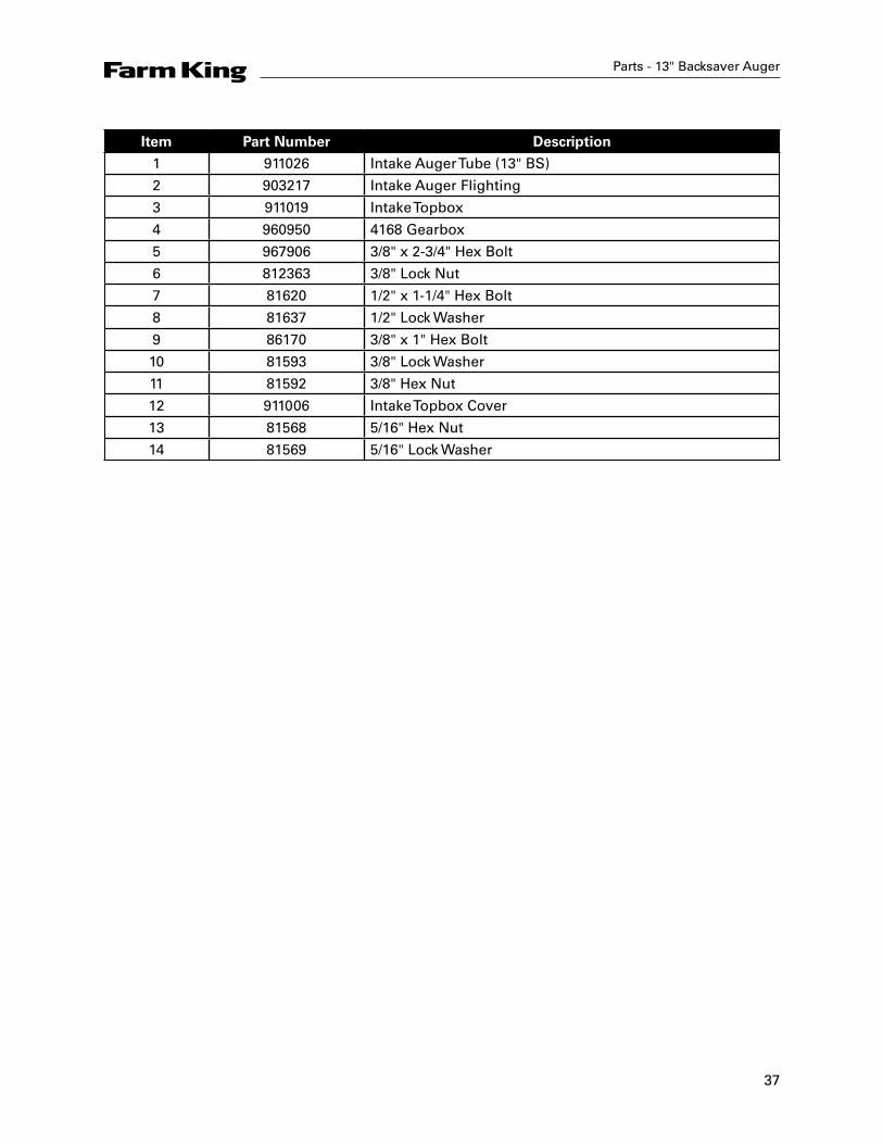
Parts - 13" Backsaver Auger
Item Part Number Description
1 911026 Intake Auger Tube (13" BS)
2 903217 Intake Auger Flighting
3 911019 Intake Topbox
4 960950 4168 Gearbox
5 967906 3/8" x 2-3/4" Hex Bolt
6 812363 3/8" Lock Nut
7 81620 1/2" x 1-1/4" Hex Bolt
8 81637 1/2" Lock Washer
9 86170 3/8" x 1" Hex Bolt
10 81593 3/8" Lock Washer
11 81592 3/8" Hex Nut
12 911006 Intake Topbox Cover
13 81568 5/16" Hex Nut
14 81569 5/16" Lock Washer
38
Parts - 13" Backsaver Auger
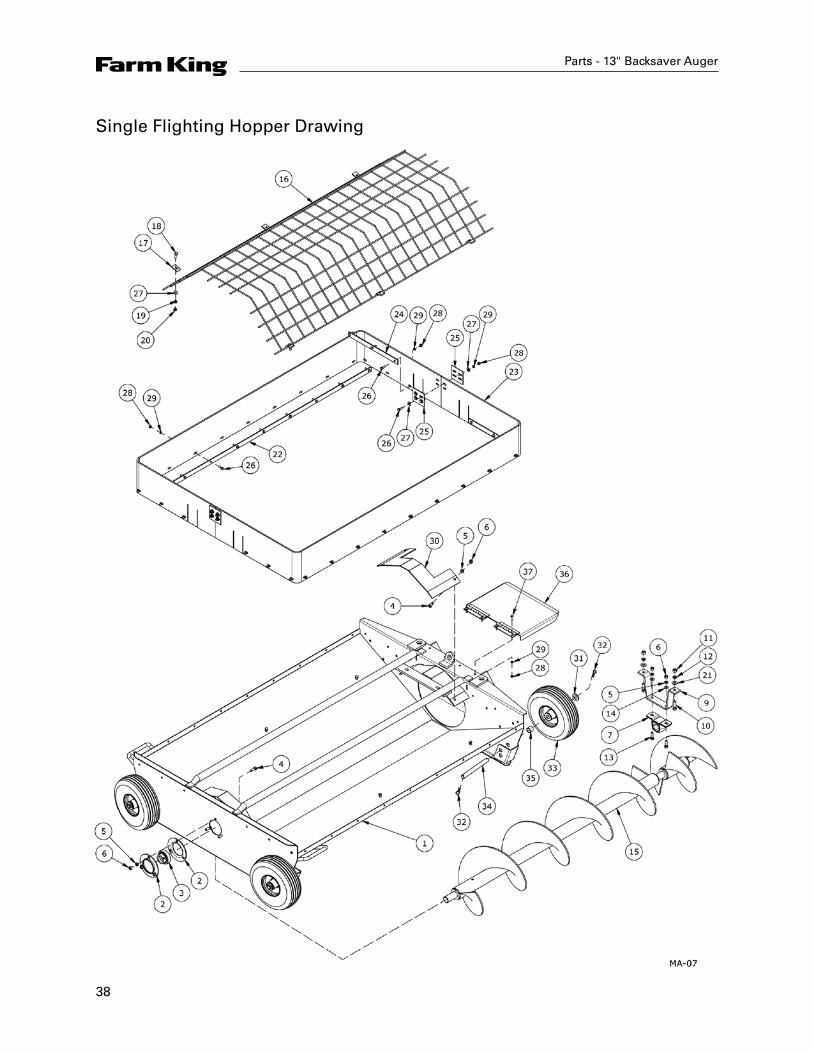
Single Flighting Hopper Drawing

39
Item Part Number Description
1 911043 Single Flighting Hopper
2 961675 Bearing Flange 72MS
3 961676 1-1/4" Bearing AEL206-104 (RHP #1230)
4 86170 3/8" x 1" Hex Bolt
5 81593 3/8" Lock Washer
6 81592 3/8" Hex Nut
7 960658 1-1/4" Wooden Bearing & Flange Set
8 960659 1-1/4" Wooden Bearing Only
9 911123 Bearing Holder
10 81599 7/16" x 1-1/2" Hex Bolt
11 81614 7/16" Hex Nut
12 81615 7/16" Lock Washer
13 86171 3/8" x 1-1/4" Hex Bolt
14 84039 3/8" Flat Washer
15 960359 Intake Hopper Flighting
16 911040 Hopper Flighting Guard
17 910898 Cage Mounting Plate
18 812026 5/16" x 1" Hex Bolt
19 81569 5/16" Lock Washer
20 81568 5/16" Hex Nut
21 84000 7/16" Flat Washer
22 960660 Rubber Reinforcement 1" x 57.25"
23 911399 Rubber Standard Hopper Edging
24 960661 Reinforcement Rubber 1" x 13"
25 903483 3" x 3" Rubber Connector Plate
26 81527 1/4" x 1" Hex Bolt
27 81546 5/16" Flat Washer
28 81544 1/4" Hex Nut
29 81545 1/4" Lock Washer
30 960929 Extension Deflector 7.5" x 16.25"
31 84050 3/4" SAE Flat Washer
32 961012 #16 Hair Pin Clip
33 960714 Wheel with Tire 4.10/3.50
34 910916 Pin Hopper Wheel 19 x 187 mm
35 910917 Spacer Wheel 25 mm OD x 19 mm
36 911039 Intake Lid
37 81525 1/4" x 3/4" Hex Bolt
Parts - 13" Backsaver Auger

40
Parts - 13" Backsaver Auger
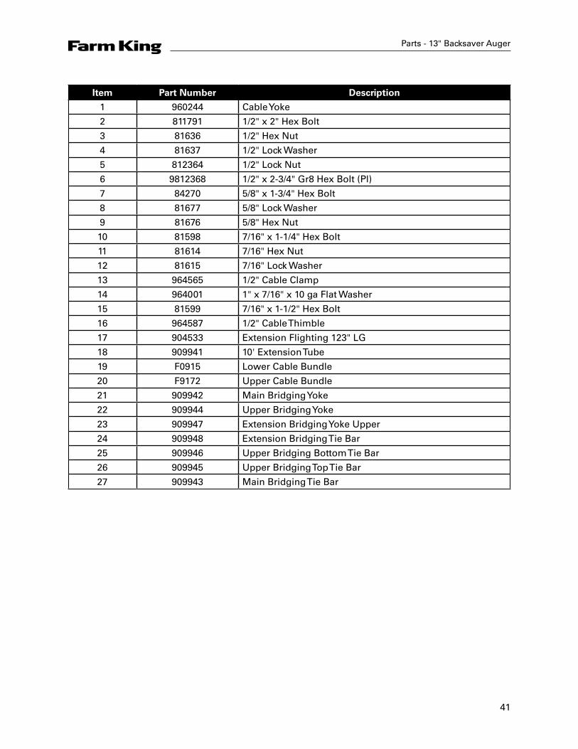
13" x 10' Extension Drawing
41
Parts - 13" Backsaver Auger
Item Part Number Description
1 960244 Cable Yoke
2 811791 1/2" x 2" Hex Bolt
3 81636 1/2" Hex Nut
4 81637 1/2" Lock Washer
5 812364 1/2" Lock Nut
6 9812368 1/2" x 2-3/4" Gr8 Hex Bolt (Pl)
7 84270 5/8" x 1-3/4" Hex Bolt
8 81677 5/8" Lock Washer
9 81676 5/8" Hex Nut
10 81598 7/16" x 1-1/4" Hex Bolt
11 81614 7/16" Hex Nut
12 81615 7/16" Lock Washer
13 964565 1/2" Cable Clamp
14 964001 1" x 7/16" x 10 ga Flat Washer
15 81599 7/16" x 1-1/2" Hex Bolt
16 964587 1/2" Cable Thimble
17 904533 Extension Flighting 123" LG
18 909941 10' Extension Tube
19 F0915 Lower Cable Bundle
20 F9172 Upper Cable Bundle
21 909942 Main Bridging Yoke
22 909944 Upper Bridging Yoke
23 909947 Extension Bridging Yoke Upper
24 909948 Extension Bridging Tie Bar
25 909946 Upper Bridging Bottom Tie Bar
26 909945 Upper Bridging Top Tie Bar
27 909943 Main Bridging Tie Bar
42
Parts - 13" Backsaver Auger
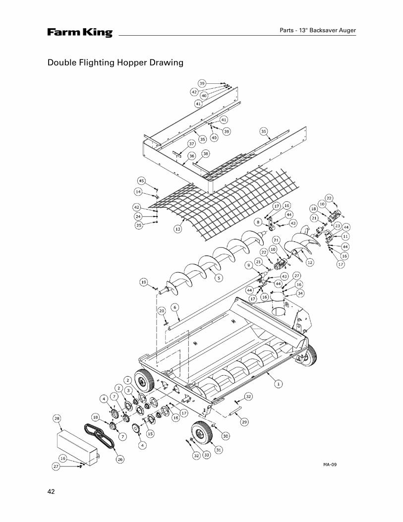
Double Flighting Hopper Drawing
43
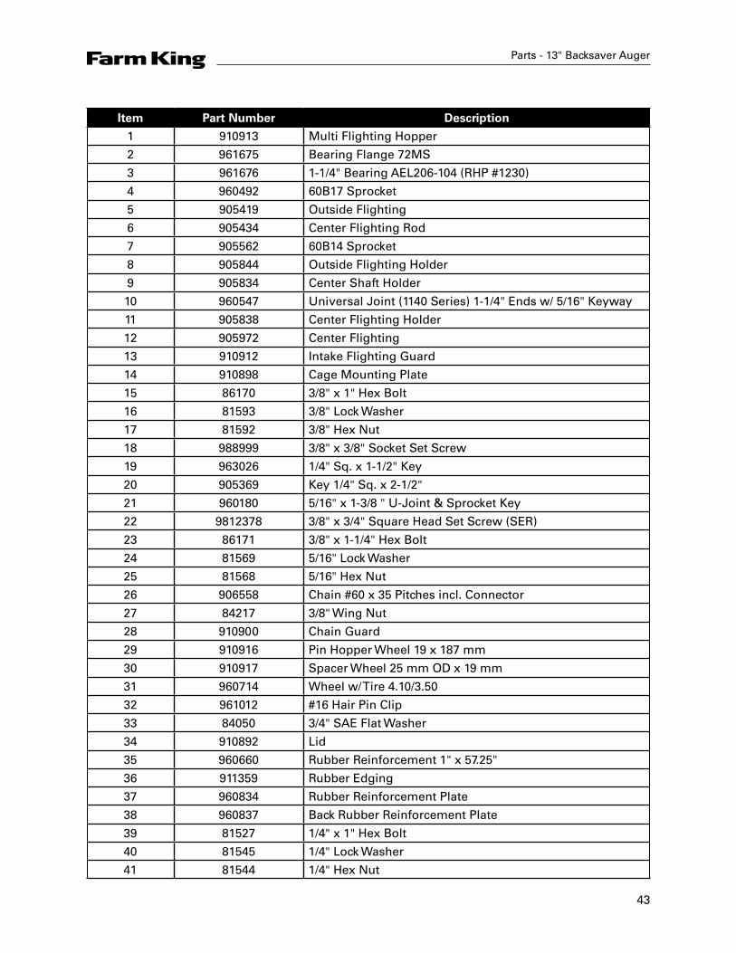
Parts - 13" Backsaver Auger
Item Part Number Description
1 910913 Multi Flighting Hopper
2 961675 Bearing Flange 72MS
3 961676 1-1/4" Bearing AEL206-104 (RHP #1230)
4 960492 60B17 Sprocket
5 905419 Outside Flighting
6 905434 Center Flighting Rod
7 905562 60B14 Sprocket
8 905844 Outside Flighting Holder
9 905834 Center Shaft Holder
10 960547 Universal Joint (1140 Series) 1-1/4" Ends w/ 5/16" Keyway
11 905838 Center Flighting Holder
12 905972 Center Flighting
13 910912 Intake Flighting Guard
14 910898 Cage Mounting Plate
15 86170 3/8" x 1" Hex Bolt
16 81593 3/8" Lock Washer
17 81592 3/8" Hex Nut
18 988999 3/8" x 3/8" Socket Set Screw
19 963026 1/4" Sq. x 1-1/2" Key
20 905369 Key 1/4" Sq. x 2-1/2"
21 960180 5/16" x 1-3/8 " U-Joint & Sprocket Key
22 9812378 3/8" x 3/4" Square Head Set Screw (SER)
23 86171 3/8" x 1-1/4" Hex Bolt
24 81569 5/16" Lock Washer
25 81568 5/16" Hex Nut
26 906558 Chain #60 x 35 Pitches incl. Connector
27 84217 3/8" Wing Nut
28 910900 Chain Guard
29 910916 Pin Hopper Wheel 19 x 187 mm
30 910917 Spacer Wheel 25 mm OD x 19 mm
31 960714 Wheel w/ Tire 4.10/3.50
32 961012 #16 Hair Pin Clip
33 84050 3/4" SAE Flat Washer
34 910892 Lid
35 960660 Rubber Reinforcement 1" x 57.25"
36 911359 Rubber Edging
37 960834 Rubber Reinforcement Plate
38 960837 Back Rubber Reinforcement Plate
39 81527 1/4" x 1" Hex Bolt
40 81545 1/4" Lock Washer
41 81544 1/4" Hex Nut
44
Parts - 13" Backsaver Auger
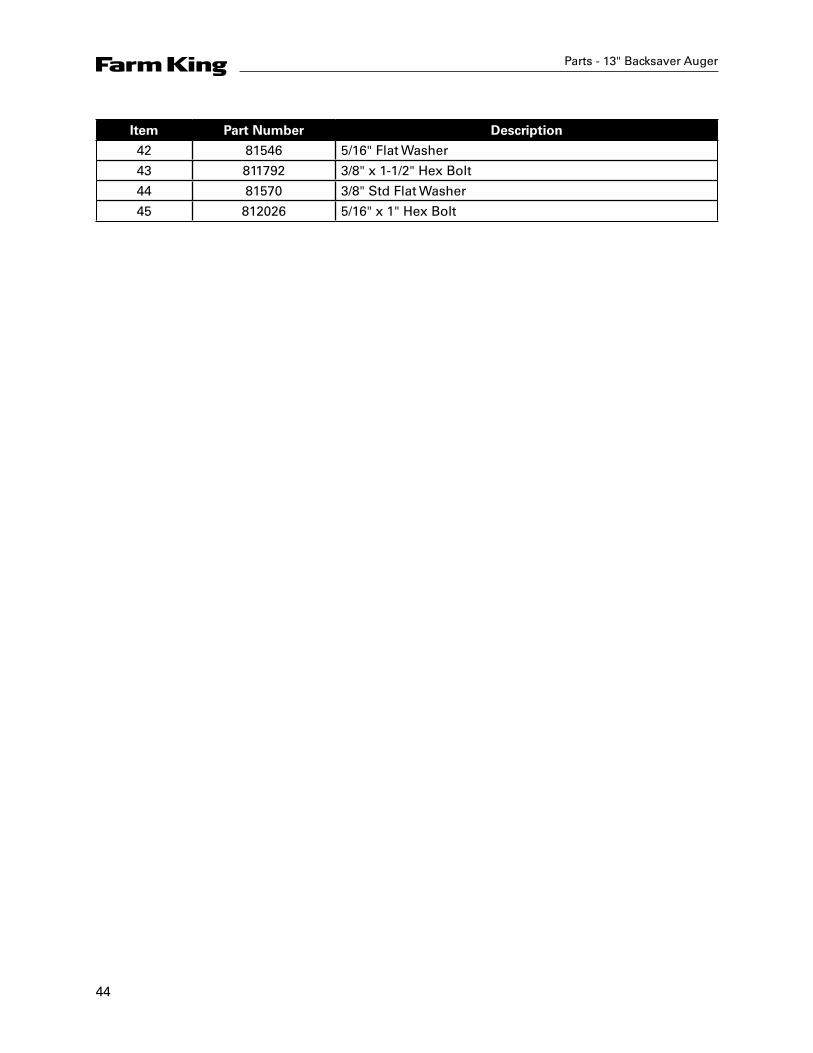
Item Part Number Description
42 81546 5/16" Flat Washer
43 811792 3/8" x 1-1/2" Hex Bolt
44 81570 3/8" Std Flat Washer
45 812026 5/16" x 1" Hex Bolt

46
Parts - 13" Backsaver Auger
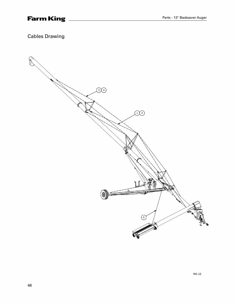
Cables Drawing
47
Parts - 13" Backsaver Auger
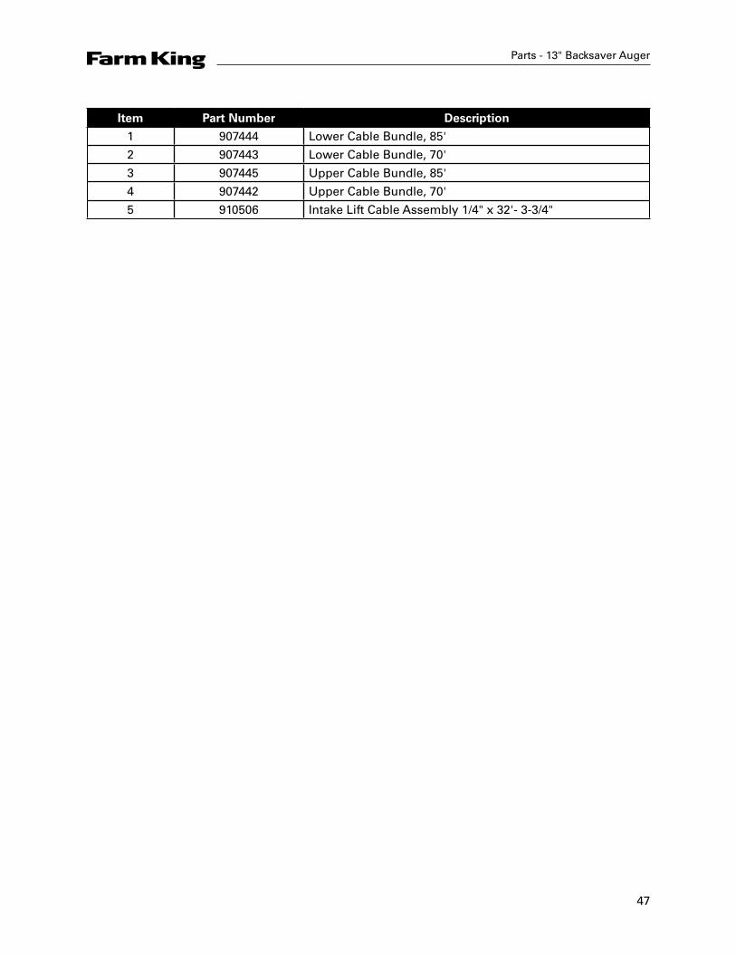
Item Part Number Description
1 907444 Lower Cable Bundle, 85'
2 907443 Lower Cable Bundle, 70'
3 907445 Upper Cable Bundle, 85'
4 907442 Upper Cable Bundle, 70'
5 910506 Intake Lift Cable Assembly 1/4" x 32'- 3-3/4"
48
Parts - 13" Backsaver Auger
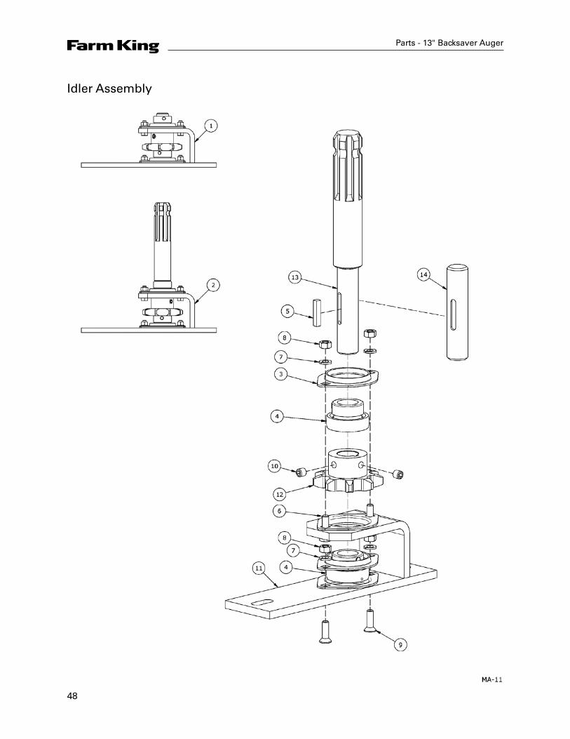
Idler Assembly
49
Parts - 13" Backsaver Auger
Item Part Number Description
1 910990 Idler Assembly
2 911142 Idler Assembly w/ Reverse
3 963009 Bearing Flange (52 MST)
4 961627 1" Bearing w/ Collar
5 960177 1/4" Sq. x 1-1/4" Key
6 812026 5/16" x 1" Hex Bolt
7 81569 5/16" Lock Washer
8 81568 5/16" Hex Nut
9 967183 5/16" x 1" Flat Head Socket Bolt
10 988999 3/8" x 3/8" Socket Set Screw
11 960531 Idler Frame
12 960717 Sprocket 9T-#80 (1" Bore)
13 911143 Reverse Idler Shaft
14 960533 Idler Shaft

50
Parts - 13" Backsaver Auger
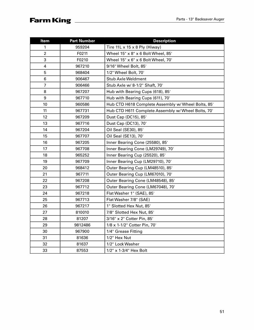
Tire Assembly Drawing
51
Parts - 13" Backsaver Auger
Item Part Number Description
1 959204 Tire 11L x 15 x 8 Ply (Hiway)
2 F0211 Wheel 15" x 8" x 6 Bolt Wheel, 85'
3 F0210 Wheel 15" x 6" x 6 Bolt Wheel, 70'
4 967210 9/16" Wheel Bolt, 85'
5 968404 1/2" Wheel Bolt, 70'
6 906467 Stub Axle Weldment
7 906466 Stub Axle w/ 8-1/2" Shaft, 70'
8 967207 Hub with Bearing Cups (618), 85'
9 967710 Hub with Bearing Cups (611), 70'
10 960586 Hub CTD H618 Complete Assembly w/ Wheel Bolts, 85'
11 967731 Hub CTD H611 Complete Assembly w/ Wheel Bolts, 70'
12 967209 Dust Cap (DC15), 85'
13 967716 Dust Cap (DC13), 70'
14 967204 Oil Seal (SE30), 85'
15 967707 Oil Seal (SE13), 70'
16 967205 Inner Bearing Cone (25580), 85'
17 967708 Inner Bearing Cone (LM29749), 70'
18 965252 Inner Bearing Cup (25520), 85'
19 967709 Inner Bearing Cup (LM29710), 70'
20 968412 Outer Bearing Cup (LM48510), 85'
21 967711 Outer Bearing Cup (LM67010), 70'
22 967208 Outer Bearing Cone (LM48548), 85'
23 967712 Outer Bearing Cone (LM67048), 70'
24 967218 Flat Washer 1" (SAE), 85'
25 967713 Flat Washer 7/8" (SAE)
26 967217 1" Slotted Hex Nut, 85'
27 810010 7/8" Slotted Hex Nut, 85'
28 81207 3/16" x 2" Cotter Pin, 85'
29 9812486 1/8 x 1-1/2" Cotter Pin, 70'
30 967900 1/4" Grease Fitting
31 81636 1/2" Hex Nut
32 81637 1/2" Lock Washer
33 87553 1/2" x 1-3/4" Hex Bolt
52
Parts - 13" Backsaver Auger
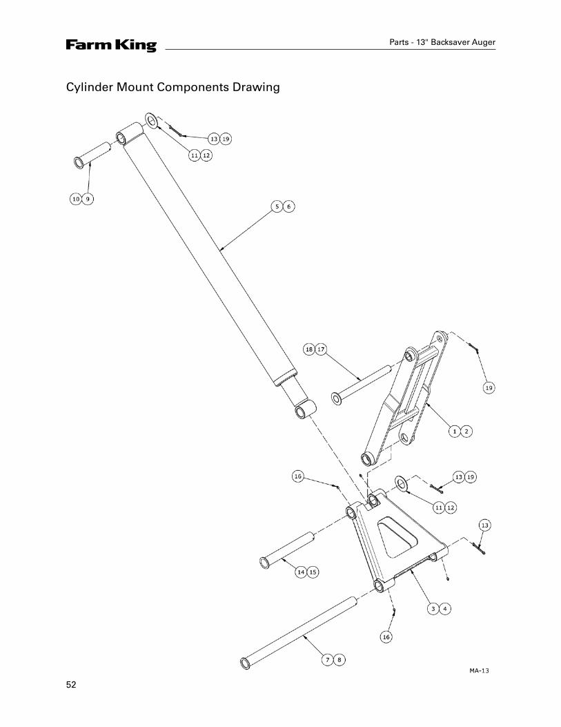
Cylinder Mount Components Drawing

53
Parts - 13" Backsaver Auger
Item Part Number Description
1 907342 Pivot Yoke, 85'
2 960624 Pivot Yoke, 70'
3 960688 Connecting Link, 85'
4 960625 Connecting Link, 70'
5 F0445 Cylinder (5" x 52-3/8"), 85'
6 F9778 Cylinder (4-1/2" x 42-1/2"), 70'
7 F0035 Ø2" x 34-3/16" Connecting Link Pin, 85'
8 F0034 Ø2" x 27-15/16" Connecting Link Pin, 70'
9 960692 Ø2" x 9" Lower Lift Arm, Top Cylinder Pin, 85'
10 960691 1-1/2" x 8-11/16" Top Cylinder Pin, 70'
11 967153 2" x 10 ga Narrow Rim Washer
12 967135 1-1/2" x 10 ga Narrow Rim Washer, 70'
13 967162 5/16" x 3" Cotter Pin
14 960690 2" x 14-13/16" Bottom Cylinder Pin, 85'
15 960628 1-1/2" x 12-3/8 Bottom Cylinder Pin, 70'
16 967164 Drive-In Grease Zerk
17 960694 1-1/2" x 16-11/16" Top Yoke Pin, 85'
18 960630 1-1/2" x 13-11/16" Top Yoke Pin, 70'
19 81210 1/4" x 2" Cotter Pin

54
Undercarriage Pivot Ring Drawing
Parts - 13" Backsaver Auger
Main Bridging Yoke Drawing

56
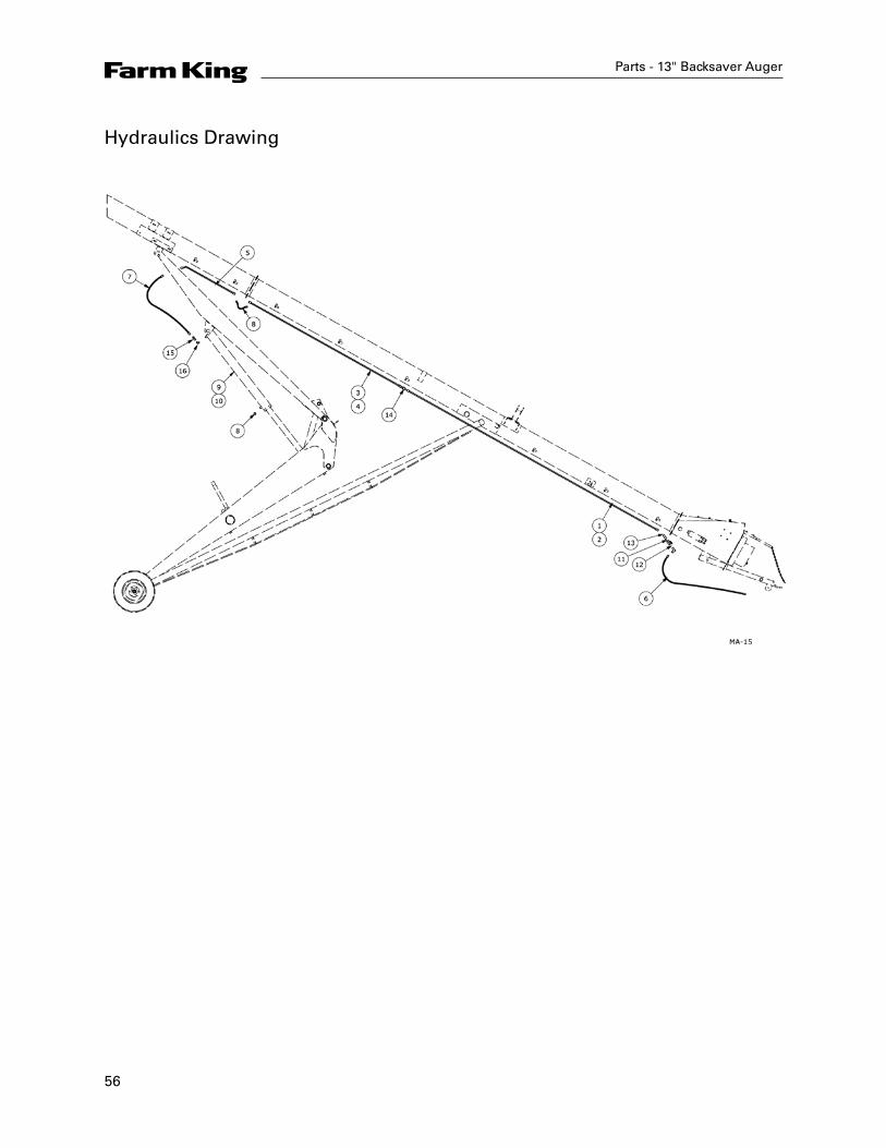
Hydraulics Drawing
Parts - 13" Backsaver Auger
57
Parts - 13" Backsaver Auger
Item Part Number Description
1 960467 5/8" OD x 15'-10" Hydraulic Line - 85'
2 960468 5/8" OD x 13'-4" Hydraulic Line - 70'
3 960200 5/8" OD x 9'-7" Hydraulic Line - 85'
4 960144 5/8" OD x 11' Hydraulic Line - 70'
5 960143 5/8" OD x 36" Hydraulic Line - 85'
6 960466 1/2" x 112" Hydraulic Hose (1/2" MNPT Both Ends)
7 960710 1/2" x 72" Hydraulic Hose (1/2" MNPT x 7/8" MJIC)
8 960162 1/2" x 18' Hydraulic Hose (7/8" MJIC Both Ends) - 85'
9 F0445 Cylinder (5" x 52-3/8") - 85'
10 F9778 Cylinder (4-1/2" x 42-1/2") - 70'
11 960057 1/2" Ball Valve
12 960585 1/2" x 90° Street Elbow (Stl.)
13 960152 Adaptor (7/8" MJIC to 1/2" NPT)
14 812711 Coupler, 7/8" MJIC Both Ends
15 960118 1/2" One Way Control Valve
16 906541 Elbow 90° (3/4" MORB x 1/2" MNPT)
58
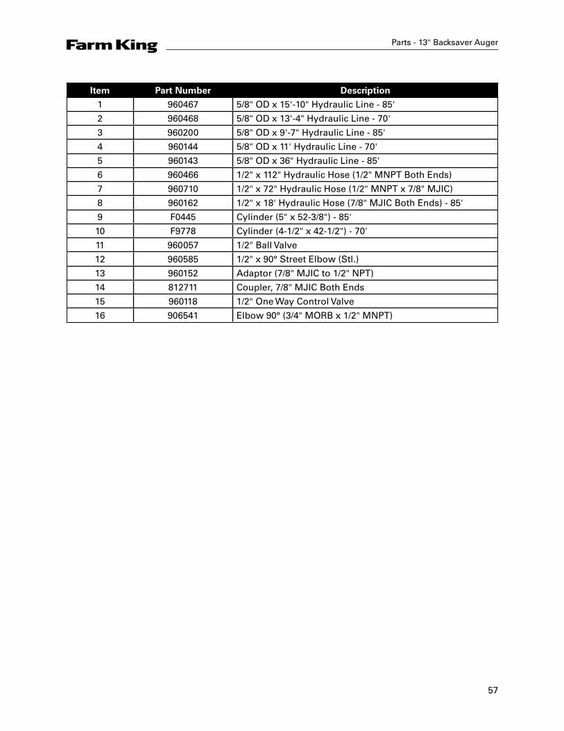
4.5 x 42.50 Cylinder Assembly Drawing
Parts - 13" Backsaver Auger
Item Part Number Description
F9778 Cylinder Complete
1 24888 4.5 Dia. Headplate
2 112564 Shaft Weldment 2.25 OD x 50.75 Lg
3 24886 4.5 Dia. Tube Weldment
4 112561 4.5 Dia. Piston
5 813407 Locknut 1.0 UNF
6 85346 O-Ring 4.125 ID x 4.50 OD Poly
7 82346 O-Ring 4.125 ID x 4.50 OD Buna
8 83346 Backup 4.125 ID x 4.50 OD x 0.06
9 812934 U-Cup 2.25 ID x 2.75 OD x 0.375
10 812979 Wiper Seal 2.25 ID x 2.75 OD x 0.25
11 812081 Plug s MORB Stl
12 82020 O-Ring 0.875 ID x 1.00 x 0.06
13 22370 Hydraulic Cylinder Decal
14 105420 Reference Plate JBI/FK Serial #

59
Parts - 13" Backsaver Auger
Item Part Number Description
F0445 Cylinder Complete
1 25123 5.0 Dia. Headplate
2 116128 Shaft Weld't 3.5 x 66
3 25122 5.0 Dia. Tube Weld't
4 111299 5.0 Dia. Piston
5 87557 Locknut 1.25 UNF
6 82425 O-Ring 4.50 ID x 5.00 OD Buna
7 83425 Backup 4.50 ID x 5.00 OD x 0.085
8 82214 O-Ring 1.00 ID x 1.25 OD Buna
9 115130 U-Cup 4.25 OD x 3.50 ID x 0.375
10 115129 Wiper Seal 3.50 ID x 4.00 OD x 0.25
11 812081 Plug 3/4 MORB Steel
12 22370 Hydraulic Cylinder Decal
13 105420 Reference Plate JBI/FK Serial #
14 116129 Stop Tube 6.00 Long
5.0 x 51.35 Cylinder Assembly Drawing
60
Parts - 13" Backsaver Auger
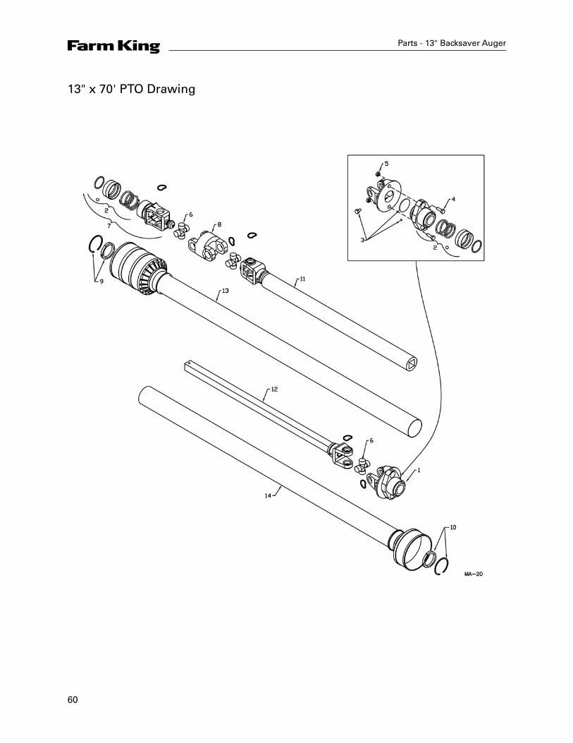
13" x 70' PTO Drawing

61
Parts - 13" Backsaver Auger
Item Part Number Description
F9552 Shaft Complete
936566 Outer Half Shaft - Tractor
908720 Inner Half Shaft - Implement
1 936277 Ball Shear Assembly
2 936433 Safety Slide Lock Repair Kit
(Collar, Spring, Retainer Ring, 2-Pawls)
3 936249 Shear Assembly Repair Kit
(3/8" x 1/2" Bolt, Lube, Blank, 31-1/4" Balls)
4 903297 Bag of 10 - Shear Bolts - 5/16" x 1" (Gr8) w/ Nuts
5 812362 5/16" Lock Nut
6 906504 Repair Kit - Extended Life (Std)
936025 Repair Kit - Optional
7 936366 Inner Splined Yoke
8 936361 CV Center Housing
9 936364 Nylon Repair Kit 21 x 26 (Bearing & Snap Ring)
10 936319 Nylon Repair Kit 20 x 26 (Bearing & Snap Ring)
11 936362 Yoke & Tube
12 936274 Yoke & Shaft
13 936363 Inner Guard
14 936273 Outer Shield
62
Parts - 13" Backsaver Auger
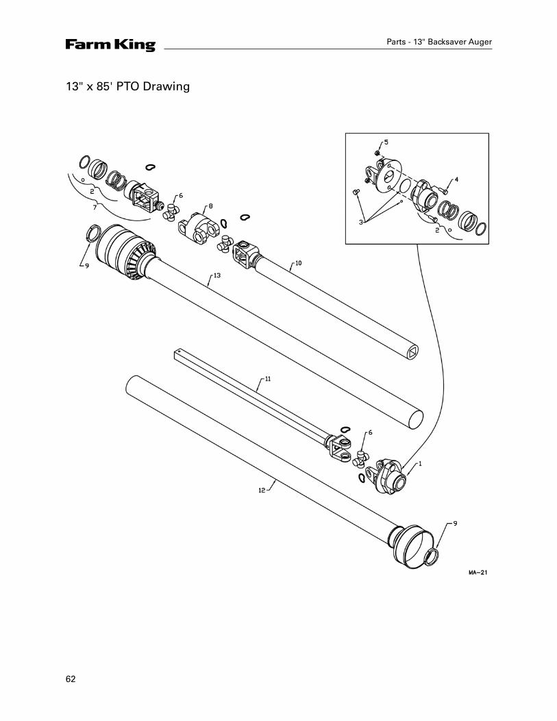
13" x 85' PTO Drawing
63
Parts - 13" Backsaver Auger
Item Part Number Description
F0608 Shaft Complete
908721 Outer Half Shaft - Tractor
908722 Inner Half Shaft - Implement
1 936432 Ball Shear Assembly
2 936199 Safety Slide Lock Repair Kit - #26-15120
(Collar, Spring, Retainer Ring, 2-Pawls)
3 936249 Shear Assembly Repair Kit
(3/8" x 1/2" Bolt, Lube, Blank 31-1/4" Balls)
4 903297 Bag of 10 - Shear Bolts - 5/16" x 1" (Gr8) w/ Nuts
5 812362 5/16" Lock Nut
6 906505 Repair Kit - Extended Life (standard)
7 936431 Inner Splined Yoke - #55241-1612
8 936436 CV Center Housing
9 908844 Nylon Repair Kit - #19-15121
10 936438 Yoke & Tube
11 936437 Yoke & Shaft
12 908843 Outer Shield - #97-21984
13 908842 Inner Guard - #96-21984
64
Parts - 13" Backsaver Auger
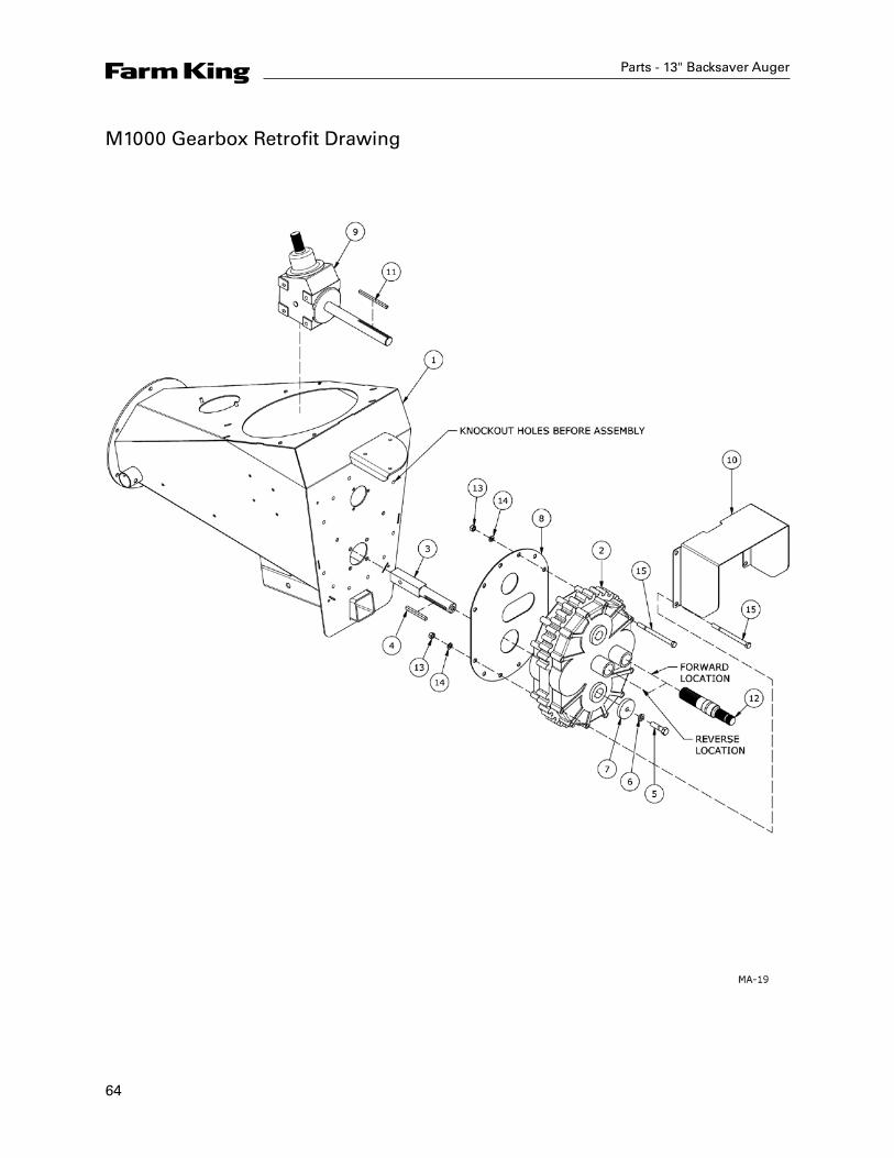
M1000 Gearbox Retrofit Drawing

65
Parts - 13" Backsaver Auger
Item Part Number Description
1 910985 Input Box
2 910927 M1000 Helical Gearbox
3 911044 M1000 Flighting Drive Shaft
4 911130 M1000 Stub Key
5 84335 5/8" x 2-1/2" Hex Bolt
6 81677 5/8" Lock Washer
7 906073 Washer Input Box 21/32" ID x 3" OD x 1/2"
8 911001 Helical Gearbox Plate
9 911131 4168 Gearbox
10 911083 M1000 Gearbox Guard
11 911163 Key 5/16" SQ x 140 mm
12 910947 M1000 Spline Stub Shaft
13 81636 1/2" Hex Nut
14 81637 1/2" Lock Washer
15 811829 1/2" 7" Hex Bolt
66
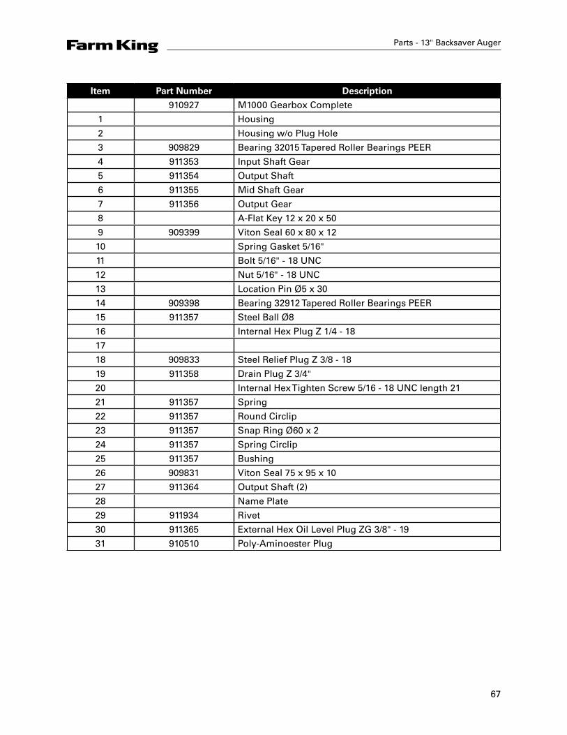
Parts - 13" Backsaver Auger
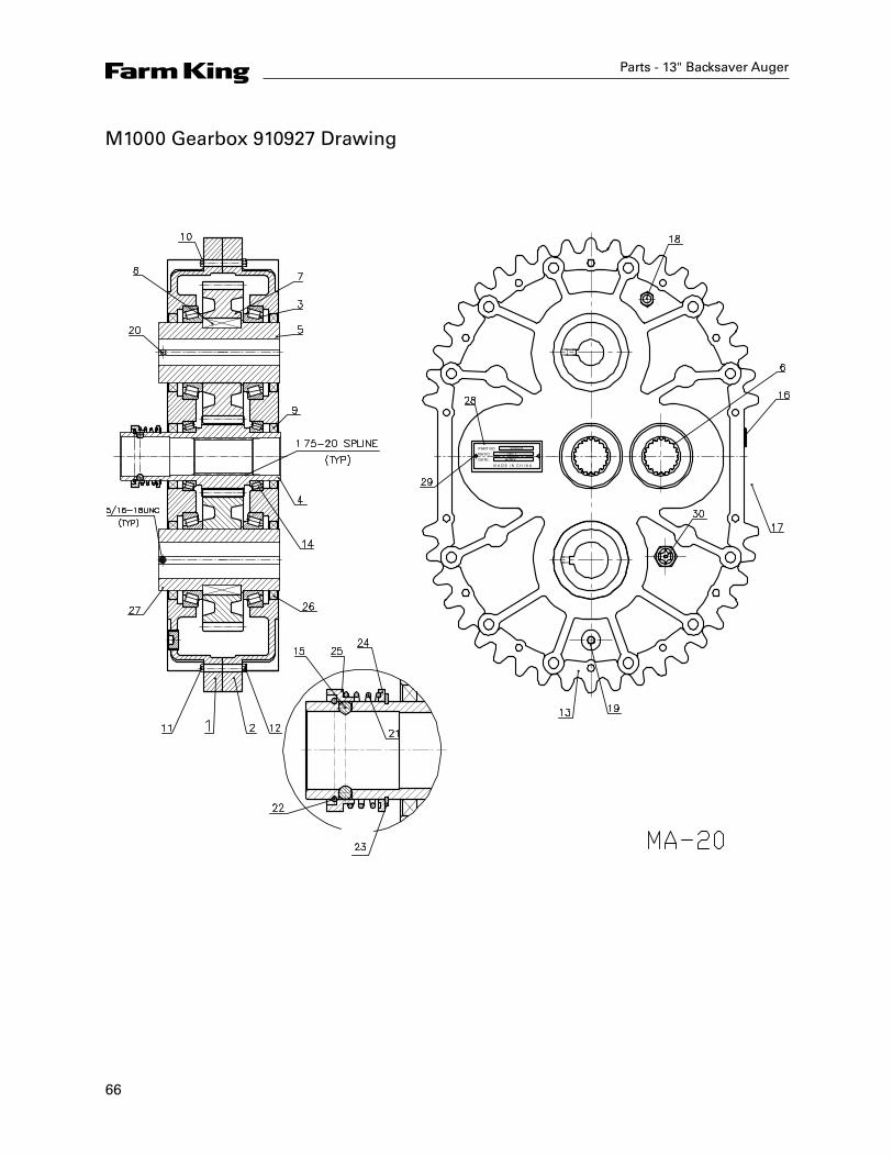
M1000 Gearbox 910927 Drawing
67
Parts - 13" Backsaver Auger
Item Part Number Description
910927 M1000 Gearbox Complete
1 Housing
2 Housing w/o Plug Hole
3 909829 Bearing 32015 Tapered Roller Bearings PEER
4 911353 Input Shaft Gear
5 911354 Output Shaft
6 911355 Mid Shaft Gear
7 911356 Output Gear
8 A-Flat Key 12 x 20 x 50
9 909399 Viton Seal 60 x 80 x 12
10 Spring Gasket 5/16"
11 Bolt 5/16" - 18 UNC
12 Nut 5/16" - 18 UNC
13 Location Pin Ø5 x 30
14 909398 Bearing 32912 Tapered Roller Bearings PEER
15 911357 Steel Ball Ø8
16 Internal Hex Plug Z 1/4 - 18
17
18 909833 Steel Relief Plug Z 3/8 - 18
19 911358 Drain Plug Z 3/4"
20 Internal Hex Tighten Screw 5/16 - 18 UNC length 21
21 911357 Spring
22 911357 Round Circlip
23 911357 Snap Ring Ø60 x 2
24 911357 Spring Circlip
25 911357 Bushing
26 909831 Viton Seal 75 x 95 x 10
27 911364 Output Shaft (2)
28 Name Plate
29 911934 Rivet
30 911365 External Hex Oil Level Plug ZG 3/8" - 19
31 910510 Poly-Aminoester Plug
68
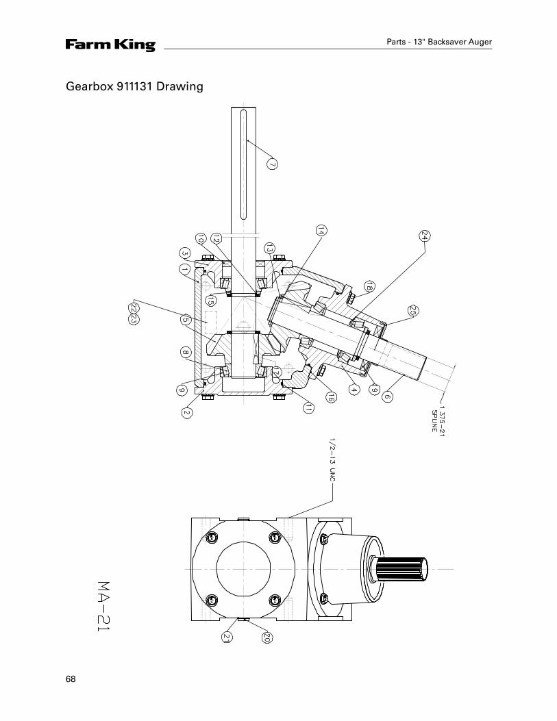
Parts - 13" Backsaver Auger
Gearbox 911131 Drawing
69
Parts - 13" Backsaver Auger
Item Part Number Description
911131 Gearbox Complete
1 960803 Housing
2 960805 End Cap
3 960810 End Cap
4 960804 Quill
5 960812 Gear, DP 4.23 Teeth 17
6 960822 Shaft, Quill
7 912026 Shaft, Cross
8 967208 Bearing Cone LM48548
9 968412 Bearing Cup LM48510
10 960817 Seal, (1.374 x 2.374 x 0.374)
11 908895 O-Ring, 105mm x 3.1mm
12 911936 Retainer Ring Ø35 x 4
13 911937 Snap Ring Ø35 x 2.5
14 911938 Spacer
15 911939 Spacer
16 960815 Gasket
17 960821 Square Key, 5/16" x 1.61"
18 960814 Capscrew, 3/8" - 16 UNC x 1.0"
19 960816 Seal, (1.374 x 2.563 x 0.374)
20 911940 Pipe Plug 3/4 - 16 UNF
21 911941 O-Ring Ø18 x 2
22 911942 Rivet
23 Label
24 960824 Grease Washer
25 960825 Shield
70
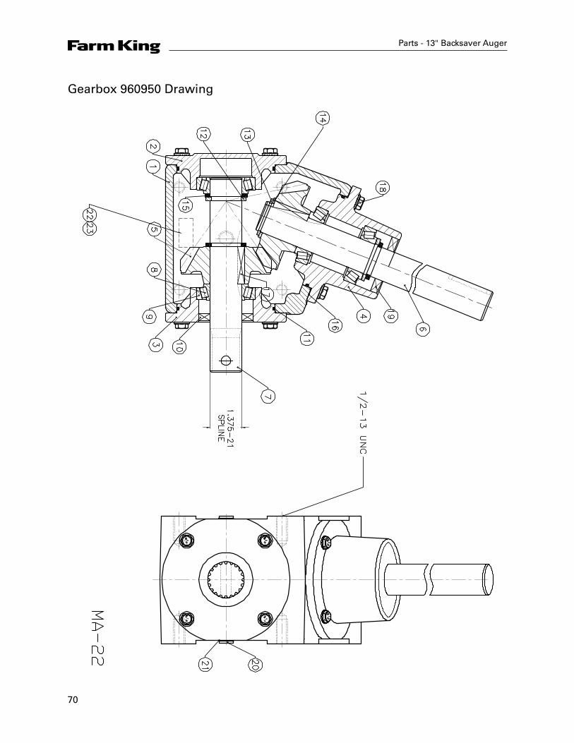
Parts - 13" Backsaver Auger
Gearbox 960950 Drawing
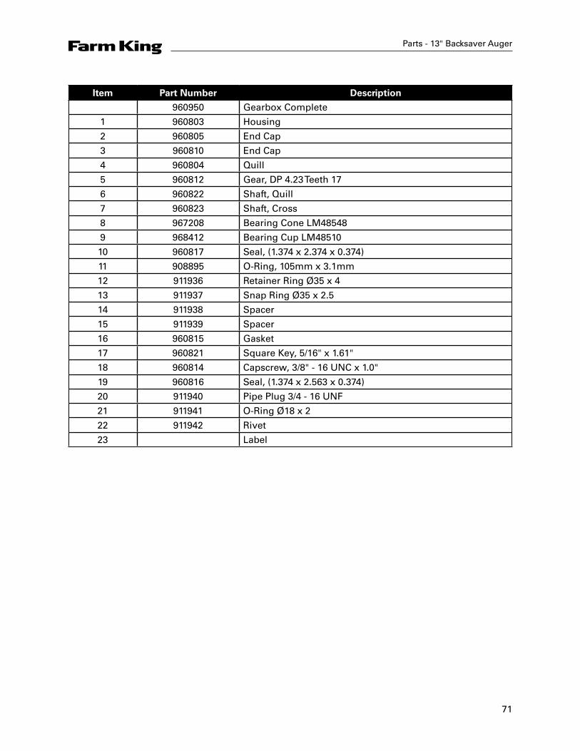
71
Parts - 13" Backsaver Auger
Item Part Number Description
960950 Gearbox Complete
1 960803 Housing
2 960805 End Cap
3 960810 End Cap
4 960804 Quill
5 960812 Gear, DP 4.23 Teeth 17
6 960822 Shaft, Quill
7 960823 Shaft, Cross
8 967208 Bearing Cone LM48548
9 968412 Bearing Cup LM48510
10 960817 Seal, (1.374 x 2.374 x 0.374)
11 908895 O-Ring, 105mm x 3.1mm
12 911936 Retainer Ring Ø35 x 4
13 911937 Snap Ring Ø35 x 2.5
14 911938 Spacer
15 911939 Spacer
16 960815 Gasket
17 960821 Square Key, 5/16" x 1.61"
18 960814 Capscrew, 3/8" - 16 UNC x 1.0"
19 960816 Seal, (1.374 x 2.563 x 0.374)
20 911940 Pipe Plug 3/4 - 16 UNF
21 911941 O-Ring Ø18 x 2
22 911942 Rivet
23 Label

72
Parts - 13" Backsaver Auger
Gearbox 960788 Drawing

73
Parts - 13" Backsaver Auger
Item Part Number Description
960788 Gearbox Complete
1 960803 Housing
2 960805 End Cap
3 960810 End Cap
4 960804 Quill
5 960812 Gear, DP 4.23 Teeth 17
6 960822 Shaft, Quill
7 960823 Shaft, Cross
8 967208 Bearing Cone LM48548
9 968412 Bearing Cup LM48510
10 960817 Seal, (1.374 x 2.374 x 0.374)
11 908895 O-Ring, 105mm x 3.1mm
12 911936 Retainer Ring Ø35 x 4
13 911937 Snap Ring Ø35 x 2.5
14 911938 Spacer
15 911939 Spacer
16 960815 Gasket
17 960821 Square Key, 5/16" x 1.61"
18 960814 Capscrew, 3/8" - 16 UNC x 1.0"
19 960816 Seal, (1.374 x 2.563 x 0.374)
20 911940 Pipe Plug 3/4 - 16 UNF
21 911941 O-Ring Ø18 x 2
22 911942 Rivet
23 Label
24 960824 Grease Washer
25 960825 Shield
74
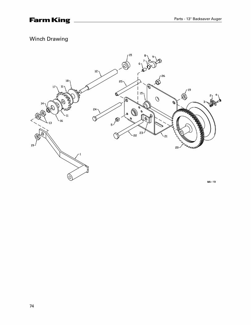
Winch Drawing
Parts - 13" Backsaver Auger
75
Parts - 13" Backsaver Auger
21Item22 Part Number Description
24125 2461S01 Handle Assembly
5621S01 Cable Keeper Kit
2 Cable Clamp
3 Lockwasher and Nut
4 Carriage Bolt
6730S00 Ratchet Kit
5 Lock Nut - 5/16
6 Ratchet Spacer
7 Ratchet Spring
8 Ratchet Pawl
9 Shoulder Bolt
11 Bushing
1563S01 Input Shaft Kit
12 Input Shaft
13 1/2" Lock Nut
14 Spacer
15 Bushing
16 Shaft Brake Disc
17 Ratchet Gear
18 Pinion & Disc Assembly
19 * 19" Lock Nut
20 * Drum Assembly
21 * Frame
22 * 1/2" x 5-3/4" Hex Bolt
23 * Drum Spacer
24 * 3/8" x 5-3/4 Hex Bolt
25 * Frame Spacer
26 * 3/8" Lock Nut
* Not available
76
Shipping Kit and Bundle Numbers
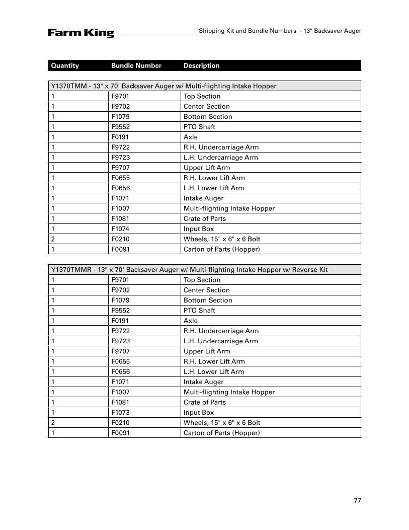
The following is a list of Kit Numbers for this product and the Bundle Numbers, Descriptions, and Quantities for each Kit.
Quantity Bundle Number Description
Y1370TM - 13" x 70' Backsaver Auger
1 F9701 Top Section
1 F9702 Center Section
1 F1079 Bottom Section
1 F9552 PTO Shaft
1 F0191 Axle
1 F9722 R.H. Undercarriage Arm
1 F9723 L.H. Undercarriage Arm
1 F9707 Upper Lift Arm
1 F0655 R.H. Lower Lift Arm
1 F0656 L.H. Lower Lift Arm
1 F1071 Intake Auger
1 F1072 Intake Hopper
1 F1081 Crate of Parts
1 F1074 Input Box
2 F0210 Wheels, 15" x 6" x 6 Bolt
1 F9180 Carton of Parts (Hopper)
Y1370TMR - 13" x 70' Backsaver Auger w/ Reverse Kit
1 F9701 Top Section
1 F9702 Center Section
1 F1079 Bottom Section
1 F9552 PTO Shaft
1 F0191 Axle
1 F9722 R.H Undercarriage Arm
1 F9723 L.H. Undercarriage Arm
1 F9707 Upper Lift Arm
1 F0655 R.H. Lower Lift Arm
1 F0656 L.H. Lower Lift Arm
1 F1071 Intake Auger
1 F1072 Intake Hopper
1 F1081 Crate of Parts
1 F1073 Input Box
2 F0210 Wheels, 15" x 6" x 6 Bolt
1 F9180 Carton of Parts (Hopper)
Shipping Kit and Bundle Numbers - 13" Backsaver Auger
77
Shipping Kit and Bundle Numbers - 13" Backsaver Auger
Quantity Bundle Number Description
Y1370TMM - 13" x 70' Backsaver Auger w/ Multi-flighting Intake Hopper
1 F9701 Top Section
1 F9702 Center Section
1 F1079 Bottom Section
1 F9552 PTO Shaft
1 F0191 Axle
1 F9722 R.H. Undercarriage Arm
1 F9723 L.H. Undercarriage Arm
1 F9707 Upper Lift Arm
1 F0655 R.H. Lower Lift Arm
1 F0656 L.H. Lower Lift Arm
1 F1071 Intake Auger
1 F1007 Multi-flighting Intake Hopper
1 F1081 Crate of Parts
1 F1074 Input Box
2 F0210 Wheels, 15" x 6" x 6 Bolt
1 F0091 Carton of Parts (Hopper)
Y1370TMMR - 13" x 70' Backsaver Auger w/ Multi-flighting Intake Hopper w/ Reverse Kit
1 F9701 Top Section
1 F9702 Center Section
1 F1079 Bottom Section
1 F9552 PTO Shaft
1 F0191 Axle
1 F9722 R.H. Undercarriage Arm
1 F9723 L.H. Undercarriage Arm
1 F9707 Upper Lift Arm
1 F0655 R.H. Lower Lift Arm
1 F0656 L.H. Lower Lift Arm
1 F1071 Intake Auger
1 F1007 Multi-flighting Intake Hopper
1 F1081 Crate of Parts
1 F1073 Input Box
2 F0210 Wheels, 15" x 6" x 6 Bolt
1 F0091 Carton of Parts (Hopper)
78
Quantity Bundle Number Description
Y1385TM - 13" x 85' Backsaver Auger
1 F9730 Top Section
1 F9731 Center Section
1 F1080 Bottom Section
1 F0608 PTO Shaft
1 F0192 Axle
1 F9734 R.H Undercarriage Arm
1 F9735 L.H. Undercarriage Arm
1 F0464 Upper Lift Arm
1 F0565 R.H. Lower Lift Arm
1 F0564 L.H. Lower Lift Arm
1 F1071 Intake Auger
1 F1072 Intake Hopper
1 F1082 Crate of Parts
1 F1074 Input Box
2 F0211 Wheels, 15" x 8" x 6 Bolt
1 F9180 Carton of Parts (Hopper)
Y1385TMR - 13" x 85' Backsaver Auger w/ Reverse Kit
1 F9730 Top Section
1 F9731 Center Section
1 F1080 Bottom Section
1 F0608 PTO Shaft
1 F0192 Axle
1 F9734 R.H Undercarriage Arm
1 F9735 L.H. Undercarriage Arm
1 F0464 Upper Lift Arm
1 F0565 R.H. Lower Lift Arm
1 F0564 L.H. Lower Lift Arm
1 F1071 Intake Auger
1 F1072 Intake Hopper
1 F1082 Crate of Parts
1 F1073 Input Box
2 F0211 Wheels, 15" x 8" x 6 Bolt
1 F9180 Carton of Parts (Hopper)
Shipping Kit and Bundle Numbers - 13" Backsaver Auger

79
Shipping Kit and Bundle Numbers - 13" Backsaver Auger
Quantity Bundle Number Description
Y1385TMM - 13" x 85' Backsaver Auger w/ Multi-flighting Intake Hopper
1 F9730 Top Section
1 F9731 Center Section
1 F1080 Bottom Section
1 F0608 PTO Shaft
1 F0192 Axle
1 F9734 R.H Undercarriage Arm
1 F9735 L.H. Undercarriage Arm
1 F0464 Upper Lift Arm
1 F0565 R.H. Lower Lift Arm
1 F0564 L.H. Lower Lift Arm
1 F1071 Intake Auger
1 F1007 Multi-flighting Intake Hopper
1 F1082 Crate of Parts
1 F1074 Input Box
2 F0211 Wheels, 15" x 8" x 6 bolt
1 F0091 Carton of Parts (Hopper)
Y1385TMMR - 13" x 85' Backsaver Auger w/ Multi-flighting Intake Hopper w/ Reverse Kit
1 F9730 Top Section
1 F9731 Center Section
1 F1080 Bottom Section
1 F0608 PTO Shaft
1 F0192 Axle
1 F9734 R.H Undercarriage Arm
1 F9735 L.H. Undercarriage Arm
1 F0464 Upper Lift Arm
1 F0565 R.H. Lower Lift Arm
1 F0564 L.H. Lower Lift Arm
1 F1071 Intake Auger
1 F1007 Multi-flighting Intake Hopper
1 F1082 Crate of Parts
1 F1073 Input Box
2 F0211 Wheels, 15" x 8" x 6 Bolt
1 F0091 Carton of Parts (Hopper)
80
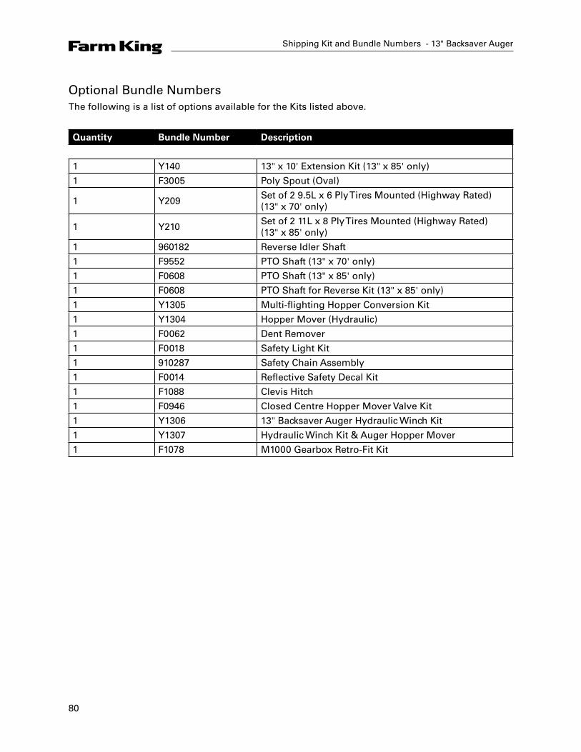
Optional Bundle NumbersThe following is a list of options available for the Kits listed above.
Quantity Bundle Number Description
1 Y140 13" x 10' Extension Kit (13" x 85' only)
1 F3005 Poly Spout (Oval)
1 Y209Set of 2 9.5L x 6 Ply Tires Mounted (Highway Rated) (13" x 70' only)
1 Y210Set of 2 11L x 8 Ply Tires Mounted (Highway Rated) (13" x 85' only)
1 960182 Reverse Idler Shaft
1 F9552 PTO Shaft (13" x 70' only)
1 F0608 PTO Shaft (13" x 85' only)
1 F0608 PTO Shaft for Reverse Kit (13" x 85' only)
1 Y1305 Multi-flighting Hopper Conversion Kit
1 Y1304 Hopper Mover (Hydraulic)
1 F0062 Dent Remover
1 F0018 Safety Light Kit
1 910287 Safety Chain Assembly
1 F0014 Reflective Safety Decal Kit
1 F1088 Clevis Hitch
1 F0946 Closed Centre Hopper Mover Valve Kit
1 Y1306 13" Backsaver Auger Hydraulic Winch Kit
1 Y1307 Hydraulic Winch Kit & Auger Hopper Mover
1 F1078 M1000 Gearbox Retro-Fit Kit
Shipping Kit and Bundle Numbers - 13" Backsaver Auger

82
Farm King Limited WarrantyThis document limits your warranty rights.
Base Limited WarrantyBuhler Industries Inc. provides this warranty only to original retail purchasers of its product. Buhler Industries Inc. warrants to such purchasers that all Buhler Industries Inc. manufactured parts and components used and serviced as provided for in the Operator’s Manual shall be free from defects in materials and workmanship for a period following delivery to the original retail purchaser of 12 months (80 days for commercial applications). This limited warranty applies only to those parts and components manufactured by Buhler Industries Inc. Parts and components manufactured by others are subject to their manufacturer’s warranties, if any.
Buhler Industries Inc. will fulfill this limited warranty by, at its option, repairing or replacing any covered part that is defective or is the result of improper workmanship, provided that the part is returned to Buhler Industries Inc. within thirty (30) days of the date that such defect or improper workmanship is, or should have been, discovered. Buhler Industries Inc. reserves the right to either inspect the product at the buyer’s location or have it returned to the factory for inspection. Parts must be returned through the selling representative and the buyer must prepay transportation charges.
Buhler Industries Inc. will not be responsible for repairs or replacements that are necessitated, in whole or part, by the use of parts not manufactured by or obtained from Buhler Industries Inc. Under no circumstances are component parts warranted against normal wear and tear. There is no warranty on product pump seals, product pump bearings, rubber product hoses, pressure gauges, or other components that require replacement as part of normal maintenance. Also: Buckets and Bucket Tines carry no warranty, Bent Spears carry no warranty, Snowblower Fan Shafts carry no warranty, Mower Blades carry no warranty, Portable Auger Parts Have Two (2) Year Warranty, Loader Parts Have Two (2) Year Warranty. The purchaser is solely responsible for determining suitability of goods sold. This warranty is expressly in lieu of all other warranties expressed or implied. Buhler Industries Inc. will in no event be liable for any incidental or consequential damages whatsoever. Nor for any sum in excess of the price received for the goods for which liability is claimed.
Repair Parts Limited WarrantyBuhler Industries Inc. warrants Farm King replacement parts purchased after the expiration of the Buhler Industries Inc. Limited Warranty, and used and serviced as provided for in the Operator’s Manual, to be free from defects in materials or workmanship for a period of thirty (30) days from the invoice date for the parts. Buhler Industries Inc. will fulfill this limited warranty by, at its option, repairing or replacing any covered part that is defective or is the result of improper workmanship, provided that the part is returned to Buhler Industries Inc. within thirty (30) days of the date that such defect or improper workmanship is, or should have been, discovered. Such parts must be shipped to Buhler Industries Inc. at the purchaser’s expense.
What is Not CoveredUnder no circumstances does this limited warranty cover any components or parts that have been subject to the following: negligence; alteration or modification not approved by Buhler Industries Inc.; misuse; improper storage; lack of reasonable and proper maintenance, service, or repair; normal wear; damage from failure to follow operating instructions; accident; and/or repairs that have been made with parts other than those manufactured, supplied, and or authorized by Buhler Industries Inc.
Warranty - 13" Backsaver Auger

83
Authorized Dealer and Labor CostsRepairs eligible for labor under this limited warranty must be made by Buhler Industries Inc. or an authorized Farm King dealer. Buhler Industries Inc. retains the exclusive discretion to determine whether it will pay labor costs for warranty repairs or replacements, and the amount of such costs that it will pay and the time in which the repairs will be made. If Buhler Industries Inc. determines that it will pay labor costs for warranty work, it will do so by issuing a credit to the dealer’s or distributor’s account. Buhler Industries Inc. will not approve or pay invoices sent for repairs that Buhler Industries Inc. has not previously approved. Warranty service does not extend the original term of this limited warranty.
Warranty RequirementsTo be covered by warranty, each Farm King new product must be registered with Buhler Industries Inc. within thirty (30) days of delivery to original retail purchaser. If the customer decides to purchase replacement components before the warranty disposition of such components is determined, Buhler Industries Inc. will bill the customer for such components and then credit the replacement invoice for those components later determined to be covered by this limited warranty. Any such replacement components that are determined not be covered by this limited warranty will be subject to the terms of the invoice and shall be paid for by the purchaser.
Warranty Claims:Warranty requests must be prepared on Buhler Industries Inc. Warranty Claim Forms with all requested information properly completed. Warranty Claims must be submitted within a thirty (30) day period from date of failure repair.
Warranty Labor: Any labor subject to warranty must be authorized by Buhler Industries Inc. The labor rate for replacing defective parts, where applicable, will be credited at 100% of the dealer’s posted shop rate.
Exclusive Effect of Warranty and Limitation of Liability
TO THE EXTENT PERMITTED BY LAW, BUHLER INDUSTRIES INC. DISCLAIMS ANY WARRANTIES, REPRESENTATIONS, OR PROMISES, EXPRESS OR IMPLIED, AS TO THE QUALITY, PERFORMANCE, OR FREEDOM FROM DEFECT OF THE COMPONENTS AND PARTS COVERED BY THIS WARRANTY AND NOT SPECIFICALLY PROVIDED FOR HEREIN.
TO THE EXTENT PERMITTED BY LAW, BUHLER INDUSTRIES INC. DISCLAIMS ANY IMPLIED WARRANTIES OF MERCHANTABILITY AND FITNESS FOR A PARTICULAR PURPOSE ON ITS PRODUCTS COVERED HEREIN, AND DISCLAIMS ANY RELIANCE BY THE PURCHASER ON BUHLER INDUSTRIES INC.’S SKILL OR JUDGMENT TO SELECT OR FURNISH GOODS FOR ANY PARTICULAR PURPOSE. THE PURCHASER’S ONLY AND EXCLUSIVE REMEDIES IN CONNECTION WITH THE BREACH OR PERFORMANCE OF ANY WARRANTY ON PRODUCTS MANUFACTURED BY BUHLER INDUSTRIES INC. ARE THOSE SET FORTH HEREIN. IN NO EVENT SHALL BUHLER INDUSTRIES INC. BE LIABLE FOR INCIDENTAL OR CONSEQUENTIAL DAMAGES (INCLUDING, BY WAY OF EXAMPLE ONLY AND NOT LIMITATION, LOSS OF CROPS, LOSS OF PROFITS OR REVENUE, OTHER COMMERCIAL LOSSES, INCONVENIENCE, OR COST OF REPLACEMENT OF RENTAL EQUIPMENT). IN NO EVENT SHALL FARM KING’S CONTRACT OR WARRANTY LIABILITY EXCEED THE PURCHASE PRICE OF THE PRODUCT.
(Note that some provinces or states do not allow limitations on how long an implied warranty
Warranty - 13" Backsaver Auger
84
lasts or the exclusion or limitation of incidental or consequential damages, so the above limitations and exclusion may not apply to you.) This warranty gives you specific legal rights and you may also have other rights, which vary from province to province or state to state.
Buhler Industries Inc. neither assumes nor authorizes any person or entity, including its selling representatives, to assume any other obligations or liability in connections with the sale of covered equipment, or to make any other warranties, representations, or promises, express or implied, as to the quality, performance, or freedom from defect of the components and parts covered herein. No one is authorized to alter, modify, or enlarge this limited warranty, or its exclusions, limitations and reservations.
Corrections of defects and improper workmanship in the manner, and for the applicable time periods, provided for herein shall constitute fulfillment of all responsibilities of Buhler Industries Inc. to the purchaser, and Buhler Industries Inc. shall not be liable in negligence, contract, or on any other basis with respect to the subject equipment.
This limited warranty is subject to any existing conditions of supply which may directly affect Buhler Industries Inc.’s ability to obtain materials or manufacture replacement parts.
Buhler Industries Inc. reserves the right to make improvements in design or changes in specifications to its products at anytime, without incurring any obligation to owners of units previously sold.
Government Legislation:Warranty terms and conditions are subject to provincial or state legislation.
Important Note: This warranty does not apply to rentals.
Warranty - 13" Backsaver Auger


www.farm-king.com
a division of Buhler Industries Inc.
301 Mountain Street SouthMorden, Manitoba Canada R6M 1X7Ph.: 204.822.4467 | Fax: 204.822.6348Toll Free: 888.524.1004E-mail: [email protected]
Equipment shown is subject to change without notice. ©2010 Buhler Trading Inc. Printed in USA. TSX:BUI