operations manual - culinaire systems · remote inputs from rtus, mua, etc. will tell the system...
TRANSCRIPT

Melink Corporation (513) 965-7300 www.melinkcorp.com
OPERATIONS MANUAL
MELINK Intelli-Hood Controls
®
®
Rev. 07/05

Melink Corporation (513) 965-7300 www.melinkcorp.com
Table of Contents
2
Step 1 Start-Up & Programming 3
Step 2 Operation 13
Step 3 Maintenance 16
Step 4 Warranty 17
Page
MELINK Intelli-Hood Controls
®
®

Melink Corporation (513) 965-7300 www.melinkcorp.com
Recommended Start-Up Procedures 1
3
A
B
C
- Check each Variable Frequency Drive (VFD) to make sure the HP and voltage rating matches the fan motor. - Check each Variable Frequency Drive for proper input and output connections. - Verify each Variable Frequency Drive has separate conduit for the input and output wiring.
- Check the I/O Processor for proper input and output connections. - Check inside the I/O Processor to verify the voltage select switch is set to the proper voltage. - Check inside the I/O Processor to verify the power switch is turned on and the LED illuminated.
- Check the cable connections for each hood to make sure they are secured to the correct receptacles. - Apply power to the Variable Frequency Drives and I/O Processor by turning on the respective breakers. - Press the Light and Fan switches on the Keypad to verify the hood lights and fans turn on.
MELINK Intelli-Hood Controls
®
®

4
Melink Corporation (513) 965-7300 www.melinkcorp.com
Keypad 1
CLEAN
FAULT
HOOD
SET-UP
Customer Service: 877-477-4190 UL NSF
Listed 33x7
%
LUZ
LIGHT
VENTILADOR
FAN
100% RESET
Intelli-Hood Controls ®
® MELINK
Bar Graph (indicates the % fan speed during normal operation and indicates a menu selection in the programming mode. Also indicates the type of fault for easy trouble-shooting)
Set-up (for programming the system at start-up. Refer to Simplissimo menu)
Light Switch (turns hood lights on and off)
Bypass Switch (operates all fans at 100% speed for a selected time interval and can also reset the system)
Fan Switch (turns fans on and off)
Clean Light (flashes red/green to indicate that Optic Sensors need cleaning)
Digital Display (indicates the hood number during normal operation and displays “E” when in 100% bypass)
Fault Light (indicates a fault condition; refer to the bar graph for the type of fault.)
MELINK Intelli-Hood Controls
®
®

CLEAN
FAULT HOOD
Customer Service: 877-477-4190 UL NSF
Listed 33x7
%
LUZ
LIGHT
VENTILADOR
FAN
100% RESET
Intelli-Hood Controls ® MELINK ®
SET-UP
CLEAN
FAULT HOOD
Customer Service: 877-477-4190 UL NSF
Listed 33x7
%
LUZ
LIGHT
VENTILADOR
FAN
100% RESET
Intelli-Hood Controls ® MELINK ®
SET-UP
5
Keypad Start-Up 1
Melink Corporation (513) 965-7300 www.melinkcorp.com
The hood fans turn on. Check the lights and displays on the Keypad: 1. Check the CLEAN light. If it flashes red and green,
then proceed to Programming to perform the “Optics Alignment” check.
2. Check the FAULT light. If it is illuminated red, then recheck all cable connections, and proceed to Pro-gramming to set up Sensors and VFDs for each hood.
Press Fan Switch
Check Fan Operation
B
C
Go to the roof and check fan operation: 1. Verify the fans are operating, because you may not
be able to hear them inside the kitchen if they are running at minimum speed.
2. At the same time, verify correct rotation for every fan being controlled. If not correct, switch two of the three motor leads at the VFD.
Press Light Switch
The hood lights turn on.
A
MELINK Intelli-Hood Controls
®
®

CLEAN
FAULT HOOD
Customer Service: 877-477-4190 UL NSF
Listed 33x7
%
LUZ
LIGHT
VENTILADOR
FAN
100% RESET
Intelli-Hood Controls ® MELINK ®
SET-UP
CLEAN
FAULT HOOD
Customer Service: 877-477-4190 UL NSF
Listed 33x7
%
LUZ
LIGHT
VENTILADOR
FAN
100% RESET
Intelli-Hood Controls ® MELINK ®
SET-UP
6
Keypad Start-Up 1
Press 100% Switch
Press the 100% / RESET Switch to operate the fans at full speed. Let the fans run at full speed for about 30 minutes to verify that the VFD does not trip out on overload.
You are now ready to program the Intelli-Hood controls using the SET-UP switches on the Keypad. Refer to the Keypad Lock-Out Feature on page 8 in order to gain access to the Simplissimo Menu shown on the next page.
Program the Controls E
Melink Corporation (513) 965-7300 www.melinkcorp.com
D
MELINK Intelli-Hood Controls
®
®
CLEAN
FAULT HOOD
Customer Service: 877-477-4190 UL NSF
Listed 33x7
%
LUZ
LIGHT
VENTILADOR
FAN
100% RESET
Intelli-Hood Controls ® MELINK ®
SET-UP
CLEAN
FAULT HOOD
Customer Service: 877-477-4190 UL NSF
Listed 33x7
%
LUZ
LIGHT
VENTILADOR
FAN
100% RESET
Intelli-Hood Controls ® MELINK ®
SET-UP
7
Programming 1
Melink Corporation (513) 965-7300 www.melinkcorp.com
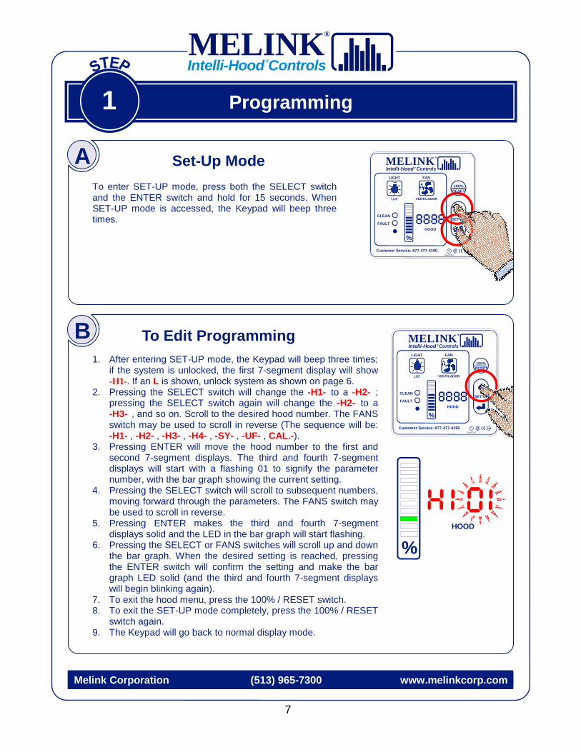
1. After entering SET-UP mode, the Keypad will beep three times; if the system is unlocked, the first 7-segment display will show -H1-. If an L is shown, unlock system as shown on page 6.
2. Pressing the SELECT switch will change the -H1- to a -H2- ; pressing the SELECT switch again will change the -H2- to a -H3- , and so on. Scroll to the desired hood number. The FANS switch may be used to scroll in reverse (The sequence will be: -H1- , -H2- , -H3- , -H4- , -SY- , -UF- , CAL.-).
3. Pressing ENTER will move the hood number to the first and second 7-segment displays. The third and fourth 7-segment displays will start with a flashing 01 to signify the parameter number, with the bar graph showing the current setting.
4. Pressing the SELECT switch will scroll to subsequent numbers, moving forward through the parameters. The FANS switch may be used to scroll in reverse.
5. Pressing ENTER makes the third and fourth 7-segment displays solid and the LED in the bar graph will start flashing.
6. Pressing the SELECT or FANS switches will scroll up and down the bar graph. When the desired setting is reached, pressing the ENTER switch will confirm the setting and make the bar graph LED solid (and the third and fourth 7-segment displays will begin blinking again).
7. To exit the hood menu, press the 100% / RESET switch. 8. To exit the SET-UP mode completely, press the 100% / RESET
switch again. 9. The Keypad will go back to normal display mode.
To enter SET-UP mode, press both the SELECT switch and the ENTER switch and hold for 15 seconds. When SET-UP mode is accessed, the Keypad will beep three times.
To Edit Programming
A Set-Up Mode
B
0
HOOD
%
MELINK Intelli-Hood Controls
®
®

CLEAN
FAULT HOOD
Customer Service: 877-477-4190 UL NSF
Listed 33x7
%
LUZ
LIGHT
VENTILADOR
FAN
100% RESET
Intelli-Hood Controls ® MELINK ®
SET-UP
CLEAN
FAULT HOOD
Customer Service: 877-477-4190 UL NSF
Listed 33x7
%
LUZ
LIGHT
VENTILADOR
FAN
100% RESET
Intelli-Hood Controls ® MELINK ®
SET-UP
8
Programming 1
Melink Corporation (513) 965-7300 www.melinkcorp.com
Press and hold the both the SELECT switch and the ENTER switch for 15 seconds. An L (non-flashing) will show on the 4-digit display and the Keypad will beep three times. Press and hold the both the SELECT switch and the ENTER switch for 15 seconds. An -H1- will show on the 4-digit display and the Keypad will beep one time. Press 100% / RESET to exit SET-UP mode.
To Lock Programming
Press and hold the both the SELECT switch and the ENTER switch for 15 seconds. An -H1- will show on the 4-digit display and the Keypad will beep three times. Press and hold the both the SELECT switch and the ENTER switch for 15 seconds. An L will show on the 4-digit display and the Keypad will beep one time. Press 100% / RESET to exit SET-UP mode.
To Unlock Programming
MELINK Intelli-Hood Controls
®
®

Future Options More options currently under development.
BAS Input Remote inputs from BAS enable the controls or tell
the system to turn on or off.
Future Options More options currently under development.
Optic Sensors Utilizing the optic sensors allows the system to operate more efficiently by watching for any traces of effluent.
Improved Fire Safety The controls can improve fire safety by
monitoring exhaust temperature and activating the fans, sounding an alarm, and/or shut down fuel to appliances.
Intelli-Hood Features & Options Standard Features
& Benefits
On/Off Options
Temperature Control Options
Optics Control Options
Auxiliary Input Options
Auxiliary Output Options
Additional Options
Improved Energy Efficiency The controls improve energy efficiency by reducing the exhaust and make-up
fan speeds during idle periods.
Improved Kitchen Comfort The controls can improve kitchen
comfort by reducing the supply of hot/humid MUA and reduce hood noise.
Improved Occupant Health The controls can improve IAQ by
monitoring CO2 levels and increasing exhaust & supply speeds if necessary.
Improved HVAC Life The controls extend HVAC life by
reducing run tie and thus wear and tear on equipment, as well as providing soft-starts for the exhaust and supply fans.
Manual On/Off On/Off via keypad fan button;
if active this will always override any other on/off method.
Auto On/Off On/Off via temperature sensors;
On temperature may be programmed.
Remote Enable Programmable setting
that requires external interlock to allow fans to start.
Remote On/Off On/Off via the dry input terminals
on the I/O board.
Scheduling On/Off via scheduled times;
may be programmed for specific days of the week.
Comfort Mode Space and supply air sensors can determine if free cooling may be
utilized and will override the temperature span to increase fan speed and act as an economizer.
Manual Temp Span Temperature span is manually set through the programmable menu.
Auto Temp Span Auto temp span will adjust to utilize
the entire temperature span and optimize energy savings.
Fire Safety If programmed, fans will activate in
case of a temperature alarm to possibly avert a fire condition.
Future Options More options currently under development.
HVAC Input Remote inputs from RTUs, MUA, etc. will tell the system either heating or cooling is taking place, and algorithms
temporarily adjust the effective temperature span to help maximize the effectiveness of the process.
IAQ Sensors Remote inputs from humidity,
CO, CO2 sensors or BAS system that may adjust fan speed.
Appliance Input Arrange for automatic fan speed adjustment
based on state of cooking equipment.
System Relay Programmable Form-C relay with
capacity of 15A @ 230VAC
System 24VAC Output 24VAC programmable output based in system menu. Can be used for alarm output, fan/equipment interlock, etc.
Hood 24VAC Output 24VAC programmable output for each hood. Can be used for alarm output,
fan/equipment interlock, etc.
Remote Access Analog or wireless feature that allows
the controls system to be remotely monitored and serviced.
Integral Datalogger System has on-board logger that will track fan operation
for up to three weeks.
Shunt-Trip Shutdown Ability to ramp EFs to full speed and shut down supply fans with simple
jumper setting during startup.
MELINK Intelli-Hood Controls
®
®
Melink Corporation (513) 965-7300 www.melinkcorp.com
9

Programming: Simplissimo 1
Melink Corporation (513) 965-7300 www.melinkcorp.com
01 02 03 04 05 06 07 08 09 10
Bar Graph
Exhaust Temp Span
Min. Fan Speed
Max. Fan Speed
Exhaust Temp. Alarm
Hood 24VAC Output
No. Hood Sensors
Auto On/Off
VFD Address
Add. VFD Address
Short-Cycle Ratio
10 70-85F Auto 100% FLASH AUD350F 24/7 No Sensors
9 70-80F 90% 95% FLASH AUD300F Fault 1O See
Scheduling in System
Menu
No Add. VFD
8 Auto TempSpan 80% 90% FLASH
AUD250F Mom Rel 4T/1O 15&16 80%
7 75-150 70% 85% FLASH AUD200F MUA Cool 3T/1O 13&14 70%
6 75-140 60% 80% FLASH AUD150F MUA Heat 2T/1O Heat-20% 11&12 60%
5 75-130 50% 75% FLASH 350F
MUA Damper 1T/1O Heat-15% No VFD 9&10 50%
4 75-120 40% 70% FLASH 300F Fans On 4T Heat-10% 4 8 40%
3 75-110 30% 65% FLASH 250F Smoke 3T Heat-5% 3 7 30%
2 75-100 20% 60% FLASH 200F
Exhaust Temp 2T Heat-0% 2 6 20%
1 75-90 10% 55% FLASH 150F No 1T No 1 5 No
11 12 13 14 15 16 17 18 19
Bar Graph
Hood Relay
Input (Dry)
Relay Inputs
to Utilize
Optic Sensor
Address* Scheduling Temp
Span Min Auto. On/Off Temp.
CFM Ratio for MUA/
AUX Output Cable
Length VFD
Software
10 T-Stat & 90% None
9 T-Stat & 80% 95F/80F 9
8 T-Stat & 75% None Sched.
1, 2, 3 90F/80F 8
7 T-Stat & 70% System 1, 2 Sched. 1, 3 85F/80F 7
6 T-Stat & 60%
Hood & System 2 Sched. 2, 3 95F/75F 6 IMO PC
5 T-Stat & 50%
Hood & System 1 Sched. 1, 2 85F 90F/75F 5 Control
Tech
4 100% on Closure System 2 Hood 4 Sched. 3
Only 80F 85F/75F 4 ABB
3 Rem Enable System 1 Hood 3 Sched. 2
Only 75F 80F/70F 3 Delta
2 Rem On/Off
Hood & System 1,2 Hood 2 Sched. 1
Only 70F 75F/70F 2 GE
1 No Hood Only Hood 1 No 65F 70F/70F 1 A-B
Enter cable length
Basic Settings
Advanced Settings
(Defaults in Red)
HOOD MENU
MELINK Intelli-Hood Controls
®
®
10
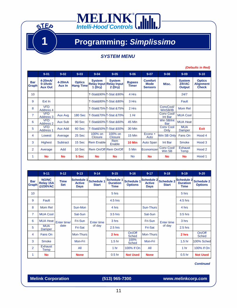
9-01 9-02 9-03 9-04 9-05 9-06 9-07 9-08 9-09 9-10
Bar Graph
4-20mA/ 0-10vdc Aux Out
4-20mA Aux In
Optics Hang Time
System Relay Input
1 (Dry)
System Relay Input
2 (Dry) Bypass Timer
Comfort Mode
Sensors Misc.
System 24VAC Output
Optics Alignment
Check
10 T-Stat&90% T-Stat &90% 4 Hrs 24/7
9 Ext In T-Stat&80% T-Stat &80% 3 Hrs Fault
8 VFD Address 4 T-Stat&75% T-Stat &75% 2 Hrs ConvCool/
WinSB/IB Mom Rel
7 VFD Address 3 Aux Avg 180 Sec T-Stat&70% T-Stat &70% 1 Hr Conv Cool/
Int Bar MUA Cool
6 VFD Address 2 Aux Sub 90 Sec T-Stat&60% T-Stat &60% 45 Min Win SB/Int
Bar MUA Heat
5 VFD Address 1 Aux Add 60 Sec T-Stat&50% T-Stat &50% 30 Min Conv Cool
Only MUA
Damper Exit
4 Lowest Average 25 Sec 100% on Closure
100% on Closure 15 Min Econo +
Auto Win SB Only Fans On Hood 4
3 Highest Subtract 15 Sec Rem Enable Rem Enable 10 Min Auto Span Int Bar Smoke Hood 3
2 Average Add 10 Sec Rem On/Off Rem On/Off 5 Min Economizer Conv Cool/Win SB
Exhaust Temp Hood 2
1 No No 5 Sec No No No No No No Hood 1
9-11 9-12 9-13 9-14 9-15 9-16 9-17 9-18 9-19 9-20
Bar Graph
NO/NC Relay 15A @230VAC
Time Set
Schedule 1 Active Days
Schedule 1 Start
Schedule 1 Duration
Time Schedule 1
Options Schedule 2
Active Days
Schedule 2 Start
Schedule 2 Duration
Time Schedule 2
Options
10
Enter time/date
Enter time of day
5 hrs 5 hrs
9 Fault 4.5 hrs 4.5 hrs
8 Mom Rel Sun-Mon 4 hrs Sun-Thurs 4 hrs
7 MUA Cool Sat-Sun 3.5 hrs Sat-Sun 3.5 hrs
6 MUA Heat Fri-Sun 3 hrs Fri-Sun 3 hrs
5 MUA Damper Fri-Sat 2.5 hrs Fri-Sat 2.5 hrs
4 Fans On Mon-Thurs 2 hrs On/Off Sched Mon-Thurs 2 hrs On/Off
Sched
3 Smoke Mon-Fri 1.5 hr 100% Sched Mon-Fri 1.5 hr 100% Sched
2 Exhaust Temp All 1 hr 100% If On All 1 hr 100% If On
1 No None 0.5 hr Not Used None 0.5 hr Not Used
Enter time of day
11
Programming: Simplissimo 1
Melink Corporation (513) 965-7300 www.melinkcorp.com
(Defaults in Red)
SYSTEM MENU
Continued
MELINK Intelli-Hood Controls
®
®

9-21 9-22 9-23 9-24 9-25 9-26 9-27 9-28 9-29 9-30
Bar Graph
Schedule 3 Active Days
Schedule 3 Start
Schedule 3 Duration
Time Schedule 3
Options Keypad
Function Disable
Cmft. Mode Space Temp
Cmft. Mode Supply Temp
MUA Heat If Kitchen <
MUA Heat If Supply <
MUA Cool If Kitchen >
10 20 hrs 77 74F 80F
9 18 hrs 76 73F 65F 79F
8 Sun-Thurs 16 hrs Byp+Lights 75 72 72F 63F 78F
7 Sat-Sun 14 hrs Fans+Byp 74 71 71F 60F 77F
6 Fri-Sun 12 hrs Fans+ Lights 73 70 70F 58F 76F
5 Fri-Sat 10 hrs Bypass 72 69 69F 55F 75F
4 Mon-Thurs 8 hrs On/Off Sched Lights 71 68 68F 53F 74F
3 Mon-Fri 6 hrs 100% Sched Fans 70 67 67F 50F 73F
2 All 4 hrs 100% If On All 69 66 66F 48F 72F
1 None 2 hrs Not Used No 68 Tk>To 65F 45F 71F
9-31 9-32 9-33 9-34 9-35 9-36 9-37 9-38 9-39 9-40
Bar Graph
Add. MUA Address
AUX VFD Software
Gain for AUX Input
Modem Options
Data Log Sample
Rate
US / SI Units
Selection
Day On/ Day Off
Monitoring Smoke Density
Fire Safety
Full Speed @ Start
10 150%
9 140%
8 130%
7 120% 5 min
6 31,32,33 IMO PC 110% 3 min 5 Min.
5 31,32 Control Tech 100% 2 min 4 Min.
4 33 ABB 90% Wireless 1 min 24H Degrees C Proportional 3 Min.
3 32 Delta 80% 9+Auto-Dial 30 sec 12H Degrees C Heavy All Hoods 2 Min.
2 31 GE 70% Auto-Dial 10 sec 24H Degrees F Active Medium Alarm Hood
Only 1 Min.
1 No A-B 60% No No 12H Degrees F Disabled Light No No
Enter time of day
12
Programming: Simplissimo 1
Melink Corporation (513) 965-7300 www.melinkcorp.com
(Defaults in Red)
SYSTEM MENU
MELINK Intelli-Hood Controls
®
®

CLEAN
FAULT HOOD
Customer Service: 877-477-4190 UL NSF
Listed 33x7
%
LUZ
LIGHT
VENTILADOR
FAN
100% RESET
Intelli-Hood Controls ® MELINK ®
SET-UP
CLEAN
FAULT HOOD
Customer Service: 877-477-4190 UL NSF
Listed 33x7
%
LUZ
LIGHT
VENTILADOR
FAN
100% RESET
Intelli-Hood Controls ® MELINK ®
SET-UP
CLEAN
FAULT HOOD
Customer Service: 877-477-4190 UL NSF
Listed 33x7
%
LUZ
LIGHT
VENTILADOR
FAN
100% RESET
Intelli-Hood Controls ® MELINK ®
SET-UP
The fans can be operated at full speed like a conventional hood system by pressing the 100% / RESET button. This should only be used if there is noticeable smoke loss and the fans are not already running at full speed. Upon pressing this button, the bar graph will flash 100% speed and the letter “E” will be displayed with each hood desig-nation. After the preset period of time, the fan speed will return to its previous operation mode.
Press 100% Switch In Case of Emergency
Melink Corporation (513) 965-7300 www.melinkcorp.com
The hood fans turn on. Fan speed automatically varies with the heat/smoke load generated by the cooking appliances. This reduces hood noise, improves kitchen comfort, and saves energy. The bar graph on the Keypad indicates the fan speed for each hood. If the CLEAN light flashes red and green, clean the lenses on the Optic Sensors.
Sequence of Operation
Press Fan Switch B
C
Press Light Switch
The hood lights turn on.
A
2
13
MELINK Intelli-Hood Controls
®
®

If the appliances are not turned on, the fan will operate at a minimum speed of 10-50%. Once the appliances are turned on, the fan speed will increase as the exhaust air temperature increases. This normally results in the fan speed increas-ing to 50-80%.
Melink Corporation (513) 965-7300 www.melinkcorp.com
Upon detection of smoke during cooking, the Optic Sensors will bypass the Temperature Sensor and increase the fan speeds to 100%. This ensures the proper removal of smoke as well as compliance with codes that require a minimum air volume and duct air velocity. Once the smoke is removed, the fan speed will decrease based on the exhaust air temperature.
The hoods will sound very quiet when the fans are operating at minimum speed. It may sound like the hood is turned off until the fan speed increases above 50% with the heat and/or smoke load. NOTE: Hoods sound
very quiet at lower fan speeds.
Quiet Hood Operation
Smoke Detection E
F
Heat Detection D
How it Works 2
14
MELINK Intelli-Hood Controls
®
®

How it Works
During normal operation, the Key-pad bar graph will indicate the per-cent fan speed of each hood. The digital display will continually scroll through each hood connected to the system every 5 seconds.
Melink Corporation (513) 965-7300 www.melinkcorp.com
%
Exhaust Rate Scrolling
Hood 1: Exhaust rate is 40%
%
%
%
2
View Current Hood Exhaust Rates
G
View Time
View Current Exhaust Temps & Average VFD
H
%
Temp. & VFD Scrolling
Hood 3: Temp. = 120º ; VFD Speed = 50% %
%
%
Hood 1: Temp. = 115º ; VFD Speed = 40%
Hood 2: Temp. = 125º ; VFD Speed = 60%
To view the exhaust temperatures and average VFD speeds for each hood, press the selection switch one time. The exhaust temperature will be shown in the digital display, and the VFD speeds will be shown in the bar graph. It will scroll through only once, then return to showing the percent fan speeds.
Hood 4: Temp. = 110º ;
VFD Speed = 30%
Hood 2: Exhaust rate is 60%
Hood 3: Exhaust rate is 50%
Hood 4: Exhaust rate is 20%
Time = 12:25
To view the time, press the Enter key. The digital display will first show the hour and then the time of day and date. It will show this only once, then it will return to the previ-
Time Time of day = afternoon (pm)
Day = Wednesday (4th day of week)
I
15
MELINK Intelli-Hood Controls
®
®
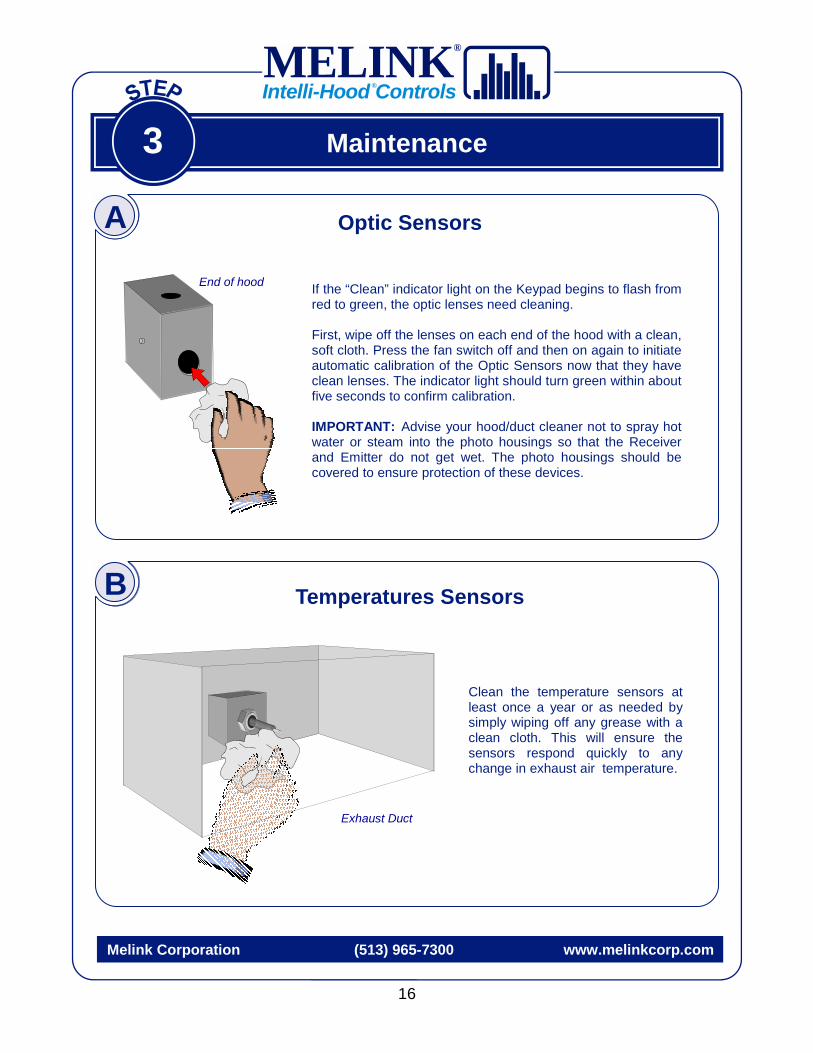
Optic Sensors
Clean the temperature sensors at least once a year or as needed by simply wiping off any grease with a clean cloth. This will ensure the sensors respond quickly to any change in exhaust air temperature.
End of hood
Melink Corporation (513) 965-7300 www.melinkcorp.com
If the “Clean” indicator light on the Keypad begins to flash from red to green, the optic lenses need cleaning. First, wipe off the lenses on each end of the hood with a clean, soft cloth. Press the fan switch off and then on again to initiate automatic calibration of the Optic Sensors now that they have clean lenses. The indicator light should turn green within about five seconds to confirm calibration. IMPORTANT: Advise your hood/duct cleaner not to spray hot water or steam into the photo housings so that the Receiver and Emitter do not get wet. The photo housings should be covered to ensure protection of these devices.
Exhaust Duct
Maintenance 3
B
A
Temperatures Sensors
16
MELINK Intelli-Hood Controls
®
®

Warranty 4
17
No returns will be accepted without prior written approval from Melink Corporation. All returned shipments must be prepaid and are subject to handling charges.
Notify the carrier in the event of damaged shipments, whether they are apparent at the time of delivery or when unpacked. File a complaint with the carrier, as the customer is responsible for the collection of damage claims.
Melink Corporation (513) 965-7300 www.melinkcorp.com
Damaged Shipments
Returns
Warranty To validate the warranty, complete and return the warranty validation form in the Owner’s Manual. Complete one form for each system installed and send to Melink Corporation at the following address within 10 days:
Melink Intelli-Hood® Attn: Warranty Validation 5140 River Valley Road
Milford, OH 45150 Melink Corporation extends this warranty to the original buyer and warrants that Melink products shall be free from original defects in workmanship and material for three years from date of shipment, provided same has been properly stored, installed, operated, maintained, and serviced. This warranty does not apply to products which have been altered or repaired without expressed written authorization from Melink Corporation, or altered or repaired in any way so as to affect its performance or its reliability, nor which have been subjected to misuse, negligence or accident. The buyer assumes responsibility for all risks and liabilities resulting from the use of these products. Melink Corporation is not responsible for the cost of removal of the defective product or part, damages due to removal, or any expenses incurred in shipping the product or part to or from the plant, or the installation of the repaired or replaced product or part.
MELINK Intelli-Hood Controls
®
®

18
Warranty 4
Melink Corporation (513) 965-7300 www.melinkcorp.com
Please complete this form and fax to Melink at (513) 527-7023, or send by mail to: Melink Corporation, 5140 River Valley Road, Milford, OH 45150.
Owner Date Company Address City State Zip Country Phone Fax Email MODEL (located inside I/O Processor) SERIAL NO. (located inside I/O Processor) Installer Address City State Zip Phone Date of Installation & Start-Up
MELINK Intelli-Hood Controls
®
®


MELINK Intelli-Hood Controls
®
®
Please let us know how we can improve our Operations Manual. We want your experience with our product to exceed all expectations.
Call Melink Customer Service at 513-965-7300 if you have any questions.