operational telecoms and security systems report
TRANSCRIPT

Exported from DOORS module ‘WI3000 - Operational Telecommunications’ Baseline 1.0
Railway Systems Contract Works
Information
Operational
Telecommunications and
Security Systems
WI3000 – Technical Specification
Security Classification: Official
Handling instructions: This document contains proprietary information. No part of
this document may be reproduced without prior written consent from the Chief
Executive Officer, HS2 Ltd.
WI 3000 Technical Specification HRS20 – Operational Telecommunications and Security Systems
Official
Contents 1 Introduction 1
1.1 Purpose 1
1.1.1 General 1
1.1.2 Application 1
1.1.3 Requirements management process 1
1.1.4 Compliance 1
1.1.5 Terminology 2
1.1.6 Standards 2
1.2 Scope 2
1.3 Works Information (WI) 3000 Structure 3
1.4 Geographical Description 5
1.4.1 HS2 Phase 1 and Phase 2a Route 5
1.4.2 Washwood Heath 7
1.4.3 Line of Route 9
1.4.4 Compounds 11
1.4.5 Use of Relocatable Equipment Buildings and Cabinets 14
1.4.6 Tunnels 14
1.4.7 Other Structures 16
1.4.8 Viaducts and Bridges 16
1.4.9 Stations 16
1.4.10 Infrastructure Maintenance Facilities 18
1.5 Principles 18
1.5.1 General Principles 18
1.5.2 System and Enterprise IT Principles 19
2 Operational Context 20
2.1 Operational Concepts 20
2.2 Operational Principles 20
2.3 Maintenance Principles 21
2.4 Users/Usability 21
2.4.1 Network Integrated Control Centre (NICC) Users 21
2.4.2 Depot Users 26
2.4.3 Station Users 26
2.4.4 Trackside Users 27
2.4.5 Train/Engineering Vehicle Users 27
2.4.6 Other Users 28
2.5 Route Capability 28
3 System Requirements 28
3.1 General Requirements 28

WI 3000 Technical Specification HRS20 – Operational Telecommunications and Security Systems
Official
3.1.1 Cable Management 29
3.2 Data Transmission Network (DTN) 30
3.2.1 DTN Safety, Integrity and Availability 35
3.2.2 DTN Connectivity 36
3.2.3 DTN Core Network Capacity 37
3.2.4 DTN Point of Presence (PoP) Locations 37
3.2.5 DTN for the HS2 CCS Lab 38
3.2.6 DTN in the System Integration Facility 39
3.2.7 DTN Reference Network 39
3.2.8 DTN Redundancy & Resilience 39
3.2.9 DTN Tertiary Route 40
3.2.10 DTN in Degraded Mode 41
3.2.11 DTN Scalability 41
3.2.12 DTN Performance 41
3.2.13 DTN Maintenance 42
3.2.14 DTN Obsolescence Management 42
3.2.15 DTN Clock Synchronisation 42
3.2.16 DTN Network Services 43
3.2.17 DTN Network and Cyber Security 44
3.2.18 DTN IP/Ethernet PoP Equipment 46
3.2.19 DTN Gateways and Firewalls 46
3.2.20 DTN Fibre Optic Network 48
3.2.21 DTN Supporting Structural Health Monitoring System (SHMS) Devices 51
3.3 Operational Telecommunications Management Platforms 51
3.3.1 DTN Network Management 53
3.3.2 Operational Telephone Management System 55
3.3.3 Fireground Remote Management System 56
3.3.4 Voice Recording Management System 56
3.3.5 Operational Telecommunications Integrated Management Terminals 57
3.4 Operational Telephone System 58
3.4.1 Operational Telephone System Safety, Integrity and Availability 59
3.4.2 Operational Telephone System Equipment 59
3.4.3 Operational Telephone System Hardware and Software Requirements 61
3.4.4 Operational Telephone System Expandability & Scalability 61
3.4.5 Operational Telephone System Degraded Modes 62
3.4.6 Operational Telephone System Functional Requirements 62
3.4.7 Operational Telephone System Additional Interface Requirements 66
3.4.8 Operational Telephone System Communications Protocols 67
3.4.9 Operational Telephone Voice Recording System 67
3.5 GSM-R 71
3.5.1 GSM-R - Background 71
WI 3000 Technical Specification HRS20 – Operational Telecommunications and Security Systems
Official
3.5.2 GSM-R - System Overview 71
3.5.3 GSM-R - General Packet Radio Service (GPRS) 72
3.5.4 GSM-R - GSM-R Reference Network 72
3.5.5 GSM-R - HS2 CCS laboratory 72
3.5.6 GSM-R - System Description 73
3.5.7 GSM-R - Functional Requirements 79
3.5.8 GSM-R - Non-Functional Requirements 86
3.5.9 GSM-R - Elements Provided by Others 91
3.5.10 GSM-R - Stations Distributed Antenna Systems (DAS) for GSM-R 91
3.6 Fireground radio system 94
3.6.1 Fireground Radio Safety, Integrity and Availability 100
3.7 Tunnel Distributed Antenna System (DAS) 100
3.7.1 Tunnel DAS - Safety, Integrity and Availability 102
3.7.2 Tunnel DAS - Interfaces & Requirements 103
3.7.3 Tunnel DAS - Radiating Cables 103
3.7.4 Tunnel DAS - Radiating Cable Mounting 104
3.7.5 Tunnel DAS - Other Antennas 106
3.7.6 Tunnel DAS - Physical Design considerations/factors 106
3.7.7 Tunnel DAS - Maintenance 106
3.7.8 Tunnel DAS - Environment and Conditions 107
3.8 Telecommunication Towers 107
3.9 Security Systems 111
3.9.1 PSIM 111
3.9.2 Video Surveillance System (VSS) 116
3.9.3 Intruder Detection System (IDS) 122
3.9.4 Perimeter Intruder Detection System (PIDS) 125
3.9.5 Electronic Access Control System (EACS) 128
3.9.6 All ESS Systems 131
3.10 Equipment Rooms and Racking 138
3.11 Radio Mast Compounds 139
3.11.1 Radio Mast Compound ESS 139
3.11.2 Radio Mast Compound Fencing 139
3.12 Rapid Deployment Sites (RDS) 140
3.13 Operational Telecommunications and Security Systems Power & UPS 141
3.13.1 Operational Telecommunications and Security Systems Power 141
3.13.2 Operational Telecommunications and Security Systems UPS 141
3.14 Operational Telecommunications and Security Systems Environmental Conditions 142
3.15 Operational Telecommunication and Security System - Spares 143
4 Interface Requirements 144
5 Quality 144
WI 3000 Technical Specification HRS20 – Operational Telecommunications and Security Systems
Official
6 RAM 144
6.1 Materials and Durability 144
6.2 Performance, Reliability and Availability 144
6.2.1 Performance 144
6.2.2 Availability 144
6.3 Maintenance and asset management 145
6.3.1 Asset Condition Monitoring 145
6.3.2 Maintenance 146
6.3.3 Obsolescence 148
6.3.4 Whole lifecycle cost 148
7 Safety 148
8 Fire Safety 151
9 Security 154
9.1 Physical Security 154
9.2 Cyber Security 155
10 Environment and Sustainability 156
11 Interoperability 158
12 Ergonomics 158
13 Sound, Noise and Vibration 165
14 Earthing and Bonding 169
14.1 Electrical Isolation 170
15 Electromagnetic Compatibility 170
16 System Integration 170
17 Assurance and Governance 170
18 Testing and Commissioning 170
19 Product Acceptance 170
20 Information management 170
21 Training 171

WI 3000 Technical Specification HRS20 – Operational Telecommunications and Security Systems
Official
Page 1
1 Introduction 1.1 Purpose
1.1.1 General
This Works Information (WI) describes the Employer’s requirements in relation to the
Contractor’s design of the works.
This Works Information describes the technical requirements of the works and the
technical constraints on how the Contractor Provides the Works.
The Employer’s process requirements related to systems integration, Contractor’s
design, Digital Engineering and transverse processes are set out in WI 0300.
The Employer’s environmental and sustainability management requirements related to
design and construction of the works are set out in WI 0285, with further technical
details described in this Works Information.
1.1.2 Application
This Works Information is applicable to HRS20.
1.1.3 Requirements management process
The Employer operates a requirements management process which captures, allocates,
verifies and validates project requirements. The details of this process are set out in
section 3.3 of WI 0300.
The requirements described in this Works Information are captured in the Employer’s
requirements management system, which uses a requirements management database
(DOORS). This Works Information is managed in DOORS and changes to this Works
Information are made in DOORS.
Any differences between this Works Information and the requirements captured in
DOORS are notified to the Project Manager.
1.1.4 Compliance
The Contractor provides compliance evidence against the items contained within the
text boxes in this Works Information, using the unique identifier as a reference in
accordance with WI 0300.
To support the management of systems integration, design management and railway
authorisation, the Employer has specified, where specifically needed, compliance
criteria (the ‘Acceptance Criteria’) in this Works Information. Where specified the
Contractor may propose alternative Acceptance Criteria to the Project Manager for
acceptance.
WI 3000 Technical Specification HRS20 – Operational Telecommunications and Security Systems
Official
Page 2
1.1.5 Terminology
This Works Information uses terms which are commonly understood in the field of
railway engineering. Further definitions are contained in WI 0020.
1.1.6 Standards
HS2 standards set out in this Works Information are listed in WI 2002.
1.2 Scope
This document forms part of the Works Information (WI) for Operational
Telecommunications and Security Systems (HRS20).
The scope of the Operational Telecommunications and Security Systems contract
includes the design, procurement, manufacture, supply, installation, supervision,
inspection, safety authorisation, testing, commissioning, and maintenance until
handover to Trial Operations of the following systems:
- Data Transmission Network (DTN, and fibre cabling);
- Operational Telephony System (OTS);
- GSM-R radio access network (BTS, antenna, FTS terminals etc...);
- Tunnel Fireground radio system;
- Tunnel Distributed Antenna System (DAS);
- Electronic Security Systems (PSIM, VSS, IDS, PIDS and Electronic Access Control); and
- Telecommunications infrastructure (telecommunications towers, REBs, trackside
cabinets, local cable management and all cabling)
Sites where Operational Telecommunications and Security Systems equipment and
services are required include the NICC, Depots, Stations, Tunnels, Viaducts, Railway
System Compounds, Radio Mast Compounds, and trackside along the HS2 route.
The Global System for Mobile Communications - Railway (GSM-R) system design, cell
planning, frequency planning and core network works required to support the
integration of the HS2 network into the national core GSM-R network will be delivered
by Network Rail. Locations for GSM-R base stations will be specified by Network Rail
and shall be supplied, installed and commissioned by the Operational
Telecommunications and Security Systems contractor (this contract) on HS2.
Elements of the Operational Telecommunications and Security Systems are specified in
National Technical Specification Notices (NTSN) and include GSM-R and communications
in tunnels. These are:
- Control, Command and Signalling National Technical Specification Notice, and
WI 3000 Technical Specification HRS20 – Operational Telecommunications and Security Systems
Official
Page 3
- Safety in Railway Tunnels National Technical Specification Notice.
A list of abbreviations relating to this WI 3000 are listed in HRS20 Operational
Telecommunications and Security Systems WI 3000 Abbreviations List [HS2-HS2-EN-LST-
000-000005].
1.3 Works Information (WI) 3000 Structure
The WI 3000 provides the requirements for the Operational Telecommunications and
Security Systems in a document form. The requirements are extracted from the DOORS
database and includes additional supporting information, and where needed, specific
acceptance criteria.
The WI 3000 is organised in to 21 Chapters.
This is Chapter 1 and provides the Introduction to the WI 3000 including a high-level
overview of the HS2 Railway, the Geographic Limits, the infrastructure and an overview
of the scope of the Operational Telecommunication and Security System to be delivered
under this contract.
Chapter 2 provides the Operational Context that provides insight into the operational
framework that the Operational Telecommunication and Security Systems will need to
perform.
Chapter 3 is the system requirements for the Operational Telecommunication and
Security Systems and has been organised by sub-system. The structure of this chapter
does not constitute a design constraint, but a basis to produce the requirements and
interfaces that need to be met by the Operational Telecommunication and Security
System.
Chapter 4 contains the Interface Requirements. The requirements are contained in the
Interface Control Document that describes the physical interface requirements for the
Operational Telecommunications and Security System. This is an extract from the
Relatic's Online Interface Management tool.
Chapter 5 to 21 are called “transversal” requirements and are a set of common railway
system requirements that the Operational Telecommunication and Security System
needs to achieve.
Chapter 5 contains Quality transversal requirements that the Operational
Telecommunications and Security System needs to demonstrate.
Chapter 6 contains the Reliability, Availability and Maintainability Requirements that the
Operational Telecommunications and Security System needs to achieve to meet the
performance targets for the HS2 Railway.
Chapter 7 contains the safety requirements for the HS2 Railway. The system
requirements in Chapter 3 have been tagged as safety requirements where the HS2
Safety assurance work has identified them as such.

WI 3000 Technical Specification HRS20 – Operational Telecommunications and Security Systems
Official
Page 4
Chapter 8 contains the fire safety requirements for the Operational
Telecommunications and Security System.
Chapter 9 contains the Security requirements. This Chapter will include both physical
and cyber security requirements.
Chapter 10 contains the Environmental and Sustainability requirements. Specific
environmental requirements for parts of the HS2 Railway will be set out in the relevant
standards.
Chapter 11 contains the Interoperability requirements for the Operational
Telecommunications and Security System.
Chapter 12 contains the Ergonomic requirements. This will need to be read in
conjunction with the WI 0300 which sets out the management process.
Chapter 13 contains the Sound, Noise and Vibration (Acoustic) requirements. This will
need to be read in conjunction with the WI 0300 which sets out the management
process.
Chapter 14 contains the Earthing and Bonding (E&B) requirements. This will need to be
read in conjunction with the WI 0300 which sets out the management process.
Chapter 15 contains the Electromagnetic Compatibility (EMC) requirements. This will
need to be read in conjunction with the WI 0300 which sets out the management
process.
Chapter 16 contains the System Integration requirements. This will need to be read in
conjunction with the WI 0300 which sets out the management process
Chapter 17 contains the Assurance and Governance requirements. This will need to be
read in conjunction with the WI 0300 which sets out the management process.
Chapter 18 contains the Testing & Commissioning requirements. This will need to be
read in conjunction with the WI 0700 which sets out the management process.
Chapter 19 contains the Product Acceptance requirements. This will need to be read in
conjunction with the WI 0300 which sets out the management process.
Chapter 20 contains the Information Management requirements. This will need to be
read in conjunction with the WI 0300 which sets out the management process.
Chapter 21 contains the Training requirements.

WI 3000 Technical Specification HRS20 – Operational Telecommunications and Security Systems
Official
Page 5
1.4 Geographical Description
1.4.1 HS2 Phase 1 and Phase 2a Route
1.4.1.1 HS2 Phase 1 Route
The overall Phase 1 route length is 230km of which ~50km is in tunnels and a third of
the route is in cuttings. Total linear length of track equates to 486km including the twin
track railway, platforms (30 in total), 6 passing / maintenance loops/sidings and 4
complex track junctions. There are over 250 bridges, including 58 viaducts, 47
underbridges and 148 overbridges. In addition, there are 115 culverts. All numbers in
this clause are indicative only and subject to final design.
HS2 Phase 1 Route
There are seven Main Works Civils packages of work spread across three geographical
areas, comprising of North, Central and South delivery areas.
Four stations exist along the Phase 1 route at Euston, Old Oak Common, Birmingham
Interchange and Birmingham Curzon Street.
The Phase 1 mainline route connects with Network Rail's Conventional Railway Network
(CRN) at Handsacre Junction. A connection with East West Rail (EWR) is provided at
Calvert Depot.
An Infrastructure Maintenance Depot (IMD) is located at Calvert.
The geographic scope of supply for HRS20 Operational Telecommunications and
Security Systems includes the whole Phase 1 line of route from Euston to Curzon Street
and connection to the West Coast Mainline at Handsacre Junction.
WI 3000 Technical Specification HRS20 – Operational Telecommunications and Security Systems
Official
Page 6
The geographic scope of supply of the Operational Telecommunications and Security
Systems includes the NICC, line of route and the railway technical interfaces with the
depots and stations. This is described in the Physical Infrastructure Diagram (see section
1.4.3) and other drawings contained in the Site Plan Pack for this contract.
The geographic scope of supply of the Operational Telecommunications and Security
Systems includes the railway technical interfaces at the boundary with the CRN at
Handsacre Junction. This connection is described in the Physical Infrastructure Diagram
(see section 1.4.3) and other drawings contained in the Site Plan Pack for this contract.
The geographic scope of supply of the Operational Telecommunications and Security
Systems includes the railway technical interfaces with the DTN external gateway at the
NICC and the external to HS2 Third Party service providers including Network Rail (and
Network Rail Telecom). This connection is described in the Physical Infrastructure
Diagram (see section 1.4.3) and other drawings contained in the Site Plan Pack for this
contract.
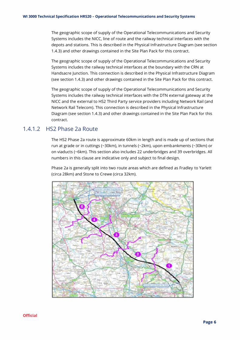
1.4.1.2 HS2 Phase 2a Route
The HS2 Phase 2a route is approximate 60km in length and is made up of sections that
run at grade or in cuttings (~30km), in tunnels (~2km), upon embankments (~30km) or
on viaducts (~6km). This section also includes 22 underbridges and 39 overbridges. All
numbers in this clause are indicative only and subject to final design.
Phase 2a is generally split into two route areas which are defined as Fradley to Yarlett
(circa 28km) and Stone to Crewe (circa 32km).

WI 3000 Technical Specification HRS20 – Operational Telecommunications and Security Systems
Official
Page 7
HS2 Phase 2a Route
The Phase 2a route connects with Network Rail's Conventional Railway Network (CRN) at
Crewe.
An Infrastructure Maintenance Depot (IMD) is located at Stone.
The geographic scope of supply for HRS20 Contract includes the whole Phase 2a line of
route from the boundary of Phase 1 to the NR connection at Crewe. This connection is
described in the Physical Infrastructure Diagram (see section 1.4.3) and other drawings
contained in the Site Plan Pack for this contract.
The geographic scope of supply of the Operational Telecommunications and Security
Systems includes the railway technical interfaces at the boundary with the CRN at
Crewe. This connection is described in the Physical Infrastructure Diagram (see section
1.4.3) and other drawings contained in the Site Plan Pack for this contract.
1.4.2 Washwood Heath
The Washwood Heath site comprises the Network Integrated Control Centre (NICC) and
the Washwood Heath Rolling Stock Depot (WWHRSD).
The layout of the Washwood Heath site is shown in drawing [1D202-EDP-UT-DPL-
NS03_NL08-200100] with general arrangement drawings of the area shown on HRS08
Washwood Heath Depot Rail Systems General Arrangement and Spatial Provisioning
sheets 1 to 3 [HRS08-WSP-ZC-DGA-NS03_NL08-000015, HRS08-WSP-ZC-DGA-
NS03_NL08-000016 and HRS08-WSP-ZC-DGA-NS03_NL08-000017].
1.4.2.1 Network Integrated Control Centre (NICC)
The NICC for the whole of the HS2 operation is located at Washwood Heath within the
boundaries of the Washwood Heath Rolling Stock Depot (WWHRSD).
The NICC acts as the command centre for all incidents and emergency situations arising
or impacting on the HS2 network, co-ordinating resources to maintain the safe
operation of the railway.
The NICC liaises with and co-ordinates staff at remote locations including infrastructure
maintenance depots and bases, train maintenance depots, train crew depots, stations
and Network Rail ROCs.
The NICC is the focal point for monitoring and managing the effect of each of the
railway systems (on their own and in aggregate) on the people experience and will be
the centre for making service-affecting decisions in the customers’ interests.
The NICC building has space allocated for Equipment Room(s). Within this space
allocation provision has been made for Operational Telecommunications and Electronic
Security Systems.

WI 3000 Technical Specification HRS20 – Operational Telecommunications and Security Systems
Official
Page 8
The NICC building contains the HS2 Operational Control Room (OCR) where all phases
of HS2's operational service will be controlled from.
The OCR follows a pod methodology, with pods covering the geographical areas of the
route and a central pod providing management oversight and the ability to take over
control of any geographical area. Additional pods are provided for Security
Management.
The current default base configuration of the geographical pods, subject to further
design and human factors work, is as follows:
- Pod 1: Phase 1: Euston – Curzon Street and Streethay / Phase 2a: Streethay Jn –
Handsacre and Crewe
- Pod 2: Phase 2b West: Streethay Jn – Manchester Piccadilly
- Pod 3: Phase 2b East: Streethay Jn – Leeds / Church Fenton
The area controlled by a pod is flexible and areas can be reallocated during incidents or
busy times.
A remote Tap-in facility is provided at Birmingham Curzon Street station to be used in
the event that the NICC OCR is not available and provides the same level of
functionality.
The Diagnostic and Technical (DAT) Room is where all maintenance workstations for all
Rail Systems will be centralised. The Operational Telecommunications and Security
Systems Contractor will need to co-ordinate with others to provide a working
environment for maintenance staff responsible for supervising and rectifying the
various Rail Systems. The Operational Telecommunications and Security Systems are
split across two workstations one for Networks and Telephony Management Systems
and one for Electronic Security Systems.
The Data Review Room is a secure room that is used by authorised people for post
incident review of VSS, voice recordings and other Data Protection Act qualifying
material away from the operating floor. The Operational Telecommunications and
Security systems will be available in the room through dedicated terminals or web-
based application to provide access to voice recordings and VSS.
The Incident Control Room (ICR) provides a dedicated, bespoke environment for
managing major service-affecting failures or incidents on the HS2 network or co-
ordinating incidents affecting HS2 services on the conventional rail network. The
Operational Telecommunications and Security Systems contractor will provide GSM-R
and Operational Telephone devices in the room.
Training facilities are provided within the NICC building to provide both one to one and
group practical scenario and classroom based training for operations controllers. NICC
Operational Control Room (OCR) systems are replicated in the Training facility to enable
all operations controllers undertake initial and ongoing training in these facilities. The

WI 3000 Technical Specification HRS20 – Operational Telecommunications and Security Systems
Official
Page 9
instructor facility enables up to four trainers to run training scenarios and role play the
external roles.
A CCS laboratory (or CCS Lab) is provided in the NICC and will be used during the design
and testing phase to demonstrate the CCS Systems are configured correctly and deliver
the required functionality.
The System Integration Facility (SIF), is a separate facility from the CCS laboratory, and is
provided in the NICC for use by all Railway Systems Contracts to demonstrate system
integration, validate interfaces and prove end to end system functionality. The
representative elements of the Operational Telecommunication Systems will be
demonstrated within the SIF to validate system design and services.
The SIF requirements for all Railway Systems Contractors, including HRS20, are captured
in a separate HS2 document (see WI 0100).
1.4.2.2 Washwood Heath Rolling Stock Depot (WWHRSD)
The WWHRSD will be the only rolling stock maintenance depot for the maintenance of
HS2's passenger trains for Phase One and 2A operations.
WWHRSD will enable the train service specification, which at its peak will see up to 18
trains per hour leaving or arriving in the depot, with a speed of 25 km/h inside the depot
and 80 km/h on the arrival and departure routes.
The WWHRSD will comprise of track and associated Overhead Catenary System (OCS),
signalling, power and telecoms. The depot will have combined stabling and servicing
sidings with associated platforms and walkways to enable cleaning and servicing of the
trains. The system architecture for the depot is shown on the Level 1 Washwood Heath
Depot system architecture diagram [HS2-HS2-IN-SAD-000-000060].
Within the depot boundaries there is space for a Radio Mast Compound with
Telecommunications Tower [see drawing HRS08-WSP-ZC-DGA-NS03_NL08-000016] to
provide radio coverage of the mainline and depot.
1.4.3 Line of Route
The line of the HS2 Phase 1 and Phase 2a route and positioning of its infrastructure
(including stations, tunnels, viaducts, bridges, track junctions and cross overs, sidings,
depots, compounds and access points) is shown on the Physical Infrastructure
Drawings.
- HS2 Phase 1 Physical Infrastructure Diagram Chainage 000+000m to Chainage
026+000m [HRS08-WSP-ZC-DSC-000-920001]
- HS2 Phase 1 Physical Infrastructure Diagram Chainage 026+000m to Chainage
048+000m [HRS08-WSP-ZC-DSC-000-920002]
- HS2 Phase 1 Physical Infrastructure Diagram Chainage 048+000m to Chainage
087+000m [HRS08-WSP-ZC-DSC-000-920003]

WI 3000 Technical Specification HRS20 – Operational Telecommunications and Security Systems
Official
Page 10
- HS2 Phase 1 Physical Infrastructure Diagram Chainage 087+000m to Chainage
127+000m [HRS08-WSP-ZC-DSC-000-920004]
- HS2 Phase 1 Physical Infrastructure Diagram Chainage 127+000m to Chainage
167+000m [HRS08-WSP-ZC-DSC-000-920005]
- HS2 Phase 1 Physical Infrastructure Diagram Chainage 167+000m to Chainage
195+000m [HRS08-WSP-ZC-DSC-000-920006]
- HS2 Phase 2a Physical Infrastructure Diagram Chainage 188+291m to Chainage
249+000m [HRS08-WSP-ZC-DSC-000-920007]
A typical arrangement for a 5km Open Route Section is shown on the Level 3 5Km
Integrated Lineside Railway Systems Architecture [HS2-HS2-IN-SAD-000-000034].
Along the line of route, in the open track sections a primary Cable Management System
(CMS) is provided by others on both sides of the track with regular interconnecting
under track crossings. The CMS route is shared with cables for CCS, Operational
Telecommunications, Security Systems and LV power. A cross-section is shown in the
following drawings HS2-HS2-CV-DSE-000-300041 and HS2-HS2-CV-DSE-000-300042.
General Arrangement Drawings (GAs) have been developed to diagrammatically
represent complex areas along the HS2 Railway.
The GA drawings depict the relationship between the various Rail Systems and the Civil
Infrastructure. The intent of these drawings is to show the arrangement of equipment
for tendering purposes and the contractors are expected to develop them as part of
their Detailed Design and interface management works.
The list of GA drawings includes:
- Chiltern South Portal (West Hyde ATS) Rail Systems General Arrangements and Spatial
Provisioning [HRS08-WSP-ZC-DGA-C001-000001];
- Maintenance Siding 1 - Stoke Mandeville Rail Systems General Arrangements and
Spatial Provisioning [HRS08-WSP-ZC-DGA-C002-000001];
- Perturbation Crossover Rail Systems General Arrangements and Spatial Provisioning
[HRS08-WSP-ZC-DGA-C002-000002];
- Calvert Rail Systems General Arrangement and Spatial Provisioning Sheet 1 to 6
[HRS08-WSP-ZC-DGA-CS06-000001 to 000006];
- Birmingham Interchange Rail Systems General Arrangements and Spatial Provisioning
Sheet 1 to 3 [HRS08-WSP-ZC-DGA-N003-000001 to 000002 and 000004];
- Washwood Heath Depot / Mainline Connection - Rail Systems General Arrangement
and Spatial Provisioning Sheet 1 to 3 [HRS08-WSP-ZC-DGA-NS03_NL08-000001 and
000003];

WI 3000 Technical Specification HRS20 – Operational Telecommunications and Security Systems
Official
Page 11
- Delta Junction Rail Systems General Arrangements and Spatial Provisioning Sheet 1 to
6 [HRS08-WSP-ZC-DGA-NS04-000001 to 000006];
- Curzon Street Approach Rail Systems General Arrangements and Spatial Provisioning
[HRS08-WSP-ZC-DGA-NS08-000001];
- Old Oak Common Station Rail Systems General Arrangements and Spatial Provisioning
Sheet 1 to 2 [HRS08-WSP-ZC-DGA-S004-000001 to 0000002];
- Euston Approach Rail Systems General Arrangements and Spatial Provisioning Sheet 1
to 3 [HRS08-WSP-ZC-DGA-SS01-000001 to 000003];
- Victoria Road Crossover Box and Access Shaft Rail Systems General Arrangement and
Spatial Provisioning [HRS08-WSP-ZC-DGA-SS04-000001]; and
- West Ruislip Siding (Gatemead Embankment) Rail Systems General Arrangements and
Spatial Provisioning [HRS08-WSP-ZC-DGA-SS05_SL07-000001].
1.4.4 Compounds
Compounds are to be used for the co-location of Railway Systems equipment along the
trackside.
The location of the compounds has been optimised to support their primary functions
whilst providing the Operational Telecommunication System space to locate trackside
equipment.
The Compounds are commonly known as Railway System Compounds and Radio Mast
Compounds (including Rapid Deployment Sites).
1.4.4.1 Railway System Compounds
Railway System Compounds (RSC) are located at strategic locations along the trace and
are there primary function is to provide intakes for the power systems both traction and
non-traction.
The typical arrangement for these sites is shown on the Level 3 Generic Railway System
Compound system architecture diagram [HS2-HS2-IN-SAD-000-000042].
Space allocation within the Railway System Compound is managed by the HV power
contractor and subject to further design development. The initial space allocation
within these compounds are shown in the following drawings:
- Burton Green [HS2-HS2-RE-DPL-000-000001];
- Ickenham [HS2-HS2-RE-DPL-000-000002];
- Quainton [HS2-HS2-RE-DPL-000-000003];
- Newlands [HS2-HS2-RE-DPL-000-000004];

WI 3000 Technical Specification HRS20 – Operational Telecommunications and Security Systems
Official
Page 12
- Bromford Bridge [HS2-HS2-RE-DPL-000-000007];
- Lyntus [HS2-HS2-RE-DPL-000-000008];
- Interchange [HS2-HS2-RE-DPL-000-000009];
- South Crewe [HS2-HS2-RE-DPL-000-000010];
- Whitmore North [HS2-HS2-RE-DPL-000-000011];
- West Hyde, Greatworth, Chipping Warden & Madeley North [HS2-HS2-RE-DPL-000-
000012];
- Gilson Road [HS2-HS2-RE-DPL-000-000013];
- Curzon Street [HS2-HS2-RE-DPL-000-000014];
- Stoney Thorpe [HS2-HS2-RE-DPL-000-000015];
- Whitfield, Drayton Lane & Mill Lane [HS2-HS2-RE-DPL-000-000017];
- Danes Moor [HS2-HS2-RE-DPL-000-000018];
- Cuttle Mill & Cappers Lane [HS2-HS2-RE-DPL-000-000019];
- Wendover [HS2-HS2-RE-DPL-000-000020];
- Leather Lane [HS2-HS2-RE-DPL-000-000022];
- Sedrup & Tibbets Farm [HS2-HS2-RE-DPL-000-000023];
- Bradnock [HS2-HS2-RE-DPL-000-000024];
- Radbourne [HS2-HS2-RE-DPL-000-000025];
- Yarnfield [HS2-HS2-RE-DPL-000-000026]; and
- Castle Bromwich [HS2-HS2-RE-DPL-000-000027].
The typical arrangement for these sites is shown on the Level 3 Generic Railway Systems
Compound system architecture diagram [HS2-HS2-IN-SAD-000-000042].
The general arrangements for Operational Telecommunication and Security Systems at
these locations are shown in the following drawings:
- Operational Telecommunications at Rail System Compound - Without a Mast [HRS08-
WSP-RC-DPL-000-000011]
- Operational Telecommunications at Rail System Compound - With a Mast [HRS08-WSP-
RC-DPL-000-000012]
For Phase 1 there are 28 RSC for Operational Telecommunications and Security Systems
use in the open route sections, 11 of which are proposed to have Telecoms Towers. For

WI 3000 Technical Specification HRS20 – Operational Telecommunications and Security Systems
Official
Page 13
Phase 2a there are 13 RSC for Operational Telecommunications and Security Systems
use in the open route sections, 6 of which are proposed to have Telecoms Towers. It
should be noted that where these compounds are adjacent to Tunnel Portals these
locations have been counted with the Portals.
1.4.4.2 Radio Mast Compounds and Rapid Deployment Sites
Radio Mast Compounds are in addition to Railway System compounds, located at
strategic locations along the trace and sited to provide optimal GSM-R coverage to
enable both voice and data communications.
For Phase 1 there are:
- 40 Radio Mast Compounds in the open route sections, and
- 2 Radio Mast Compounds in the depots (one in Calvert and one in WWHRSD).
For Phase 2a there are:
- 22 Radio Mast Compounds in the open route sections.
The typical arrangement for these sites is shown on the Level 3 Generic Radio Mast
Compound system architecture diagram [HS2-HS2-IN-SAD-000-000046].
Space in this location is managed by the Operational Telecommunications and Security
Systems contractor with allocations included for HV Power, M&E, CCS and Third Party
Telecommunications. The general arrangements are shown in the following drawings:
- Radio Mast Compound Including LV Distribution Cubicles - Option A [HRS08-WSP-RC-
DPL-000-000101]
- Radio Mast Compound Including LV Distribution Cubicles - Option B [HRS08-WSP-RC-
DPL-000-000102]
- Radio Mast Compound Including LV Distribution Cubicles - Option C [HRS08-WSP-RC-
DPL-000-000103]
- Radio Mast Compound Including LV Distribution Cubicles and HV/LV Substation -
Option A [HRS08-WSP-RC-DPL-000-000106]
- Radio Mast Compound Including LV Distribution Cubicles and HV/LV Substation -
Option B [HRS08-WSP-RC-DPL-000-000107]
- Radio Mast Compound Including LV Distribution Cubicles and HV/LV Substation -
Option C [HRS08-WSP-RC-DPL-000-000108]
Where it has been determined that Radio Mast Compound construction is not possible
at the optimal location, an alternative trackside deployment has been proposed known
as the Rapid Deployment Site (RDS) [as shown in HRS08-WSP-RC-REP-000-000005 -
HRS08 GSM-R Multi-User Rapid Deployment Solution Rationale Report].
WI 3000 Technical Specification HRS20 – Operational Telecommunications and Security Systems
Official
Page 14
There are 14 Rapid Deployment Sites with Telecoms Towers in the open route section
for phase 1.
1.4.5 Use of Relocatable Equipment Buildings and Cabinets
For Operational Telecommunications and Security Systems equipment located in the
Compounds or at a Rapid Deployment Site location then the preferred solution is for
the equipment to be located in a Relocatable Equipment Building (REB).
For Operational Telecommunications and Security Systems equipment located trackside
including the open route and in running tunnels, then the preferred solution is for the
equipment to be located in an active cabinet.
For Operational Telecommunication System fibre optic network cable joints located in
the open route trackside or in compounds the preferred solution is for the joints to be
placed in a passive cabinet.
The requirements for REBs and cabinets can be found in CCS & Comms REBs and
Cabinets Guidance document [HS2-HS2-EN-SPE-000-000004].
1.4.6 Tunnels
Tunnels make up a significant element of the total Phase 1 and 2a HS2 route (see HS2-
HS2-CV-DSC-000-000005). They are:
Phase 1
- Euston Tunnel (triple/twin bored) - 7.967km
- Old Oak Tunnel into Northolt Tunnel (twin bored) - 14.241km (combined)
- Copthall Tunnel (single bore) - 0.8km
- Chiltern Tunnel (twin bored) - 16.242km
- Wendover Tunnel (cut and cover) - 1.42km
- Greatworth Tunnel (cut and cover) - 2.101km
- Chipping Warden Tunnel (cut and cover) - 2.521km
- Long Itchington Wood Tunnel (twin bored) - 2.032km
- Burton Green Tunnel (cut and cover) - 0.761km
- Bromford Tunnel (twin bored) - 5.83km
Phase 2a
- Whitmore Heath Tunnel (cut and cover) - 1.35km
- Madley Tunnel (twin bored) - 1.025km

WI 3000 Technical Specification HRS20 – Operational Telecommunications and Security Systems
Official
Page 15
Tunnel lengths shown are provisional and subject to final design by the Main Works
Civils Contracts.
By their very nature, tunnels are space critical areas where many different systems need
to co-exist within a constrained area. Space has been provided for the Operational
Telecommunications and Security Systems and is best shown in the Tunnel Cross
Section General Arrangement Drawings:
- 9.1m Internal Diameter Tunnel Cross Section [HS2-HS2-CV-DSE-000-200123]
- 8.8m Internal Diameter Tunnel Cross Section [HS2-HS2-CV-DSE-000-200122]
- 8.1m Internal Diameter Tunnel Cross Section [HS2-HS2-CV-DSE-000-200125]
- 7.55m Internal Diameter Tunnel Cross Section [HS2-HS2-CV-DSE-000-200121]
- Cut and Cover Tunnel Cross Section [HS2-HS2-CV-DSE-000-200124]
- Precast Arch Cut and Cover Cross Section [HS2-HS2-CV-DSE-000-200115]
- HS2 Tunnel Spatial Arrangements Cross Sections General Notes Drawing [HS2-HS2-CV-
DSH-000-000002]
Tunnel Portal Buildings are typically located at either end of most tunnels along the
Phase 1 and 2a line of route for railway systems contractors to co-locate railway
systems equipment. The Portal Buildings contains an equipment room for Operational
Telecommunications and Security Systems Equipment and space adjacent to the
building for a telecommunications tower. There are 22 of Portal Buildings (18 for phase
1 and 4 for phase 2a).
Tunnel Vent & Intervention Shafts are located in long bored tunnels for the Phase 1 line
of route. Each shaft contains an Operational Telecommunications and Security Systems
Equipment room to hold comms equipment. There are 13 number of Tunnel Vent &
Intervention Shaft equipment rooms (including Park Village intervention and escape
shaft).
Tunnel Cross Passages are located at approximate intervals of 350m along the bored
tunnel length for the Phase 1 and 2a line of route by HS2 (this spacing dimension is
subject to the design for each specific tunnel) see Tunnel Cross Passage Door Schedule
[HS2-HS2-RV-SCH-000-000001].
Each cross passage contains space provision of 3.7m (width) x 2m (height) x 0.55m
(depth) adjacent to the wall on one side of the cross passage for Operational
Telecommunications and Security Systems equipment and on the opposite wall, a
smaller space for Third Party Telecommunications equipment (1.5m x 2.0m x 0.55m).
There are 106 number of cross passages with space provision for telecommunications
equipment and cabling. Cross passages are not air-conditioned, and equipment
installed must be appropriate for the environment (see D01-OPSCOM-3043) and fire
requirements (see D01-OPSCOM-112).

WI 3000 Technical Specification HRS20 – Operational Telecommunications and Security Systems
Official
Page 16
In cut and cover tunnels there are no cross passages in which to install railway systems
equipment but there are 19 cross passageways between the running tunnels providing
the evacuation route see Tunnel Cross Passage Door Schedule [HS2-HS2-RV-SCH-000-
000001].
Limited space exists for a small equipment cabinet enclosure to be positioned adjacent
to Tunnel walls. In cut and cover tunnels the preference is to install equipment mainly
in the portal buildings due to lack of space and also the need to run LV power from the
portal buildings to any cabinets and equipment installed within the tunnels.
Throughout the tunnels the primary cable containment system is provided by others
excluding the arrangements required for the Operational Telecommunications systems
radiating cables where a space provision has been made. The Operational
Telecommunications and Security Systems Contractor will be required to provide any
secondary cable containment to connect the primary cable containment to the
Operational Telecommunication and Security Systems equipment locations. The
Operational Telecommunications and Security Systems Contractor will have to co-
ordinate the design, materials and installation of the secondary cable containment with
others to ensure that the system is complete.
1.4.7 Other Structures
A special structure is provided at Sheep House Wood, across the HS2 phase 1 and
Network Rail route, to provide protection to bats at this location from the operational
railway. This structure is known as Sheep House Wood Bat Mitigation Structure
(SHWBMS) which is 0.921km long.
SHWBMS has a portal building at the North Portal with an equipment room allocated for
Operational Telecommunications and Security Systems equipment and space allocated
for Operational Telecommunications and Security Systems REB in a Compound at the
South Portal.
1.4.8 Viaducts and Bridges
There are many viaducts and bridges across the HS2 Phase 1 and 2a network including
the Colne Valley viaduct which is 3.4km long. The preference is to keep Operational
Telecommunications and Security Systems equipment off these structures as there is
limited space for anything except cables in the primary cable containment.
The general arrangement drawing for Curzon Street [HRS08-WSP-ZC-DGA-NS08-000001]
shows a special arrangement for providing Operational Telecommunications and
Security Systems equipment and services required to support HS2 operational systems
in that area.
1.4.9 Stations
Station activities are managed from the local Station Operations Room, with each HS2
station playing their part in the overall delivery of the train service.
WI 3000 Technical Specification HRS20 – Operational Telecommunications and Security Systems
Official
Page 17
All station platforms can accommodate, as a minimum, two 200m trains which may be
coupled or uncoupled.
1.4.9.1 Euston Station
Euston station is the London terminal station for HS2.
The existing design for Euston HS2 station has 11 platforms built in two stages, however
this is subject to change. It is expected that Euston HS2 station will have 10 platforms
built in a single stage. The Station Operation Room (SOR) manages all aspects of the
operational station, its station systems, the safe boarding and dispatch of trains and the
management of HS2's visitors and passengers.
Euston station has cable termination rooms and Operational Telecommunications
equipment rooms located on the platform as shown in the drawings contained in the
Site Plan Pack for this contract.
1.4.9.2 Old Oak Common Station
Old Oak Common (OOC) station is the outer London station and provides
interconnection point with services on the Great Western Mainline.
Old Oak Common station has 12 platforms that provide interconnection between HS2
and the Great Western Mainline - 6 platforms for HS2 services and 6 platforms for
services running on the Great Western Mainline. The Station Operation Room (SOR)
manages all aspects of the operational station, its station systems, the safe boarding
and dispatch of trains and the management of HS2's visitors and passengers.
Old Oak Common station has four cable termination rooms two located at either end of
the HS2 platforms and Operational Telecommunications equipment rooms located on
the platform as shown in the drawings contained in the Site Plan Pack for this contract.
1.4.9.3 Birmingham Interchange Station
Birmingham Interchange is an intermediate station which will have stopping services as
well as planned through services and provides a point of interconnection via an
Automated People Mover to Birmingham Airport, the National Exhibition Centre and
Birmingham International railway station.
Birmingham Interchange station has 4 platforms connected via a wide station
concourse which sits above the platforms and through lines. The Station Operation
Room (SOR) manages all aspects of the operational station, its station systems, the safe
boarding and dispatch of trains and the management of HS2's visitors and passengers.
Birmingham Interchange station has four cable termination rooms two located at either
end of the HS2 platforms and Operational Telecommunications equipment rooms
located on the platform as shown in the drawings contained in the Site Plan Pack for
this contract.

WI 3000 Technical Specification HRS20 – Operational Telecommunications and Security Systems
Official
Page 18
1.4.9.4 Birmingham Curzon Street Station
Curzon Street Station is the terminal station in Birmingham.
Curzon Street station has 7 platforms connected with a wide station concourse which
sits above the platforms. The Station Operation Room (SOR) manages all aspects of the
operational station, its station systems, the safe boarding and dispatch of trains and the
management of HS2's visitors and passengers.
Curzon Street station includes the remote tap in facility which is to be equipped with the
same workstations and functionality as the NICC Operation Control Room. The remote
tap-in facility is a fall-back facility that is to be used if the NICC Operation Control Room
becomes unavailable.
1.4.10 Infrastructure Maintenance Facilities
HS2 Infrastructure Maintenance activities are managed and co-ordinated from
dedicated, strategically placed facilities with the provision for stabling maintenance
plant and On-track Machines (OTM), storing materials and spares, and for providing
welfare and IT facilities for maintenance staff.
The main HS2 depot for phase 1 is the Infrastructure Maintenance Depots (IMD) at
Calvert with phase 2a supported from the Infrastructure Maintenance Base - Rail
connected (IMB-R) at Stone.
Other smaller Infrastructure Maintenance Base (IMB) are provided in strategic locations
across HS2 so that rapid response teams can quickly respond to failures.
Both Calvert IMD and Stone IMB-R have a Depot Control Room for controlling the
movement of rail mounted engineering plant and vehicles.
1.5 Principles
1.5.1 General Principles
The following general principles shall be used by the Contractor in delivering the works
and developing the systems design:
a) HS2 is planned to be a 24/7 operational railway. All designs shall adhere to ‘always up’
principles with appropriate periodic maintenance and servicing concepts to support 24-
hour operations;
b) use the built environment, technology and systems to improve security and safety;
c) flexibility to support changing technology and processes which include elements such
as energy storage, autonomy, security, biometrics and advances in telecommunications
and technology generally;

WI 3000 Technical Specification HRS20 – Operational Telecommunications and Security Systems
Official
Page 19
d) provides value for money by actively considering and monitoring of the project cost
targets in all design aspects to ensure the delivery of Security Design and Build is within
budget;
e) flexible, adaptable and scalable (without disruption to operations) for building
structure and systems as well as to support changing technology and processes;
f) ensure the design for all elements considers the testing and commissioning sequence
and strategy for future Works, to avoid any adverse impact on the commissioning
process;
1.5.2 System and Enterprise IT Principles
The following system and enterprise Information Technology Principles shall be used by
the Contractor in delivering the works and developing the design for each technology
system:
a) Innovate using proven N-1 solutions. Systems are to be based on commercially
available products (COT’s), proven technologies and ut ilising standard configurations.
Where bespoke systems or applications are the only method of servicing these
requirements, with approval from the WPO a bespoke solution may be offered in
concert with an Escrow agreement.;
b) Minimise harm to the environment and ensure sustainability outcomes are
addressed in the design;
c) Simplify the business and IT environments;
d) Ensure all solutions are secure by design;
e) Provide multi-purpose solutions where there are similar requirements for
different operational outcomes. (e.g. where VSS coverage of the same area is required
by different operational teams, duplicate streams from a single camera rather than
providing two cameras).
f) Manage information as a core corporate asset (trusted and protected).
g) Adopt a risk-based approach by designing highly available, secure, safe and
compliant solutions;
h) Adopt open standards with integration using services-based, modular solutions;
and
i) Design a systems environment that is agile, flexible, secure and open to change.
The end system incorporates flexibility, maintainability and constructability principles
that form a systematic means of ensuring a flexible, maintainable and constructible
design. These principles shall be applied throughout the project lifecycle and shall meet
the following criteria:

WI 3000 Technical Specification HRS20 – Operational Telecommunications and Security Systems
Official
Page 20
a) Flexibility – The objectives of the flexibility principles are to enable the Railway to
accommodate future modification caused by a change of use, function, technology or
regulation with minimal impact to the building fabric, operations, governmental
functions or passenger experience. These principles shall include building structure,
building systems, materials, construction methodologies or overarching design concepts
and shall be applied throughout the design at locations most likely to be impacted by
change and/or growth;
b) Maintainability – The objectives of the maintainability principles are to define
design standards that allow for safe, efficient and easy maintenance of the systems with
minimal impact to operations, or passenger experience. The principles shall address
access to cyclical replacement or cleaning of typical system devices, plant, equipment
and components. The principles shall take into consideration building systems and
services, external systems and services, materials, access and design concepts and shall
be applied throughout HS2; and
c) Constructability – The objectives of the constructability principles are to define
design standards which govern the definition of materials, methodologies, concepts and
details that allow for an efficient and simple construction process. The principles shall
take into consideration standardisation, modularity, pre-fabrication opportunities,
ability to modify materials on-site to enable them to fit where applicable, manual
handling of material to avoid safety or access issues or any other characteristics that
impact on the ease and efficiency of the construction process and future operations.
2 Operational Context 2.1 Operational Concepts
The Operational Concept is the blueprint of how the railway is to be configured,
operated and maintained in its operational phases. It informs the requirements for the
capabilities (being the people, assets, processes and systems) of the future delivery
organisations for operations and maintenance.
HS2 conforms with current UK legislation including compliance with the National
Technical Specification Notices (NTSN) and National Technical Rules (NTR).
2.2 Operational Principles
HS2 operational service is typically from 0500 to 2359 Monday to Saturday and 0800 to
2359 on Sunday.
Trains operate in the highest level of supervision available at all times.
HS2 non-passenger rolling stock operates under ETCS Level 2 and does not use ATO
functionality.
In normal circumstances, rolling stock in passenger services and empty rolling stock
operate under ETCS Level 2 and uses ATO functionality.
WI 3000 Technical Specification HRS20 – Operational Telecommunications and Security Systems
Official
Page 21
In degraded modes where ATO is unavailable, manual driving in ETCS is used.
Operational procedures for manual driving in degraded modes are based on Train
Captain competence profiles.
Lineside signage is provided in both directions to facilitate throughput of trains in
degraded modes.
ETCS national values are specifically configured for HS2, cognisant of lessons learned on
the conventional rail network.
Full bi-directional working capability is provided throughout the HS2 network and
includes all loops and platform lines.
Bi-directional movements are capable of the maximum speed profile permitted by the
infrastructure.
Bi-directional movements are subject to the same headway as those in the nominated
normal direction.
Permissive routes are available from all route setting points and are not restricted to
platform tracks.
Degraded routes are available from all route setting points.
Trains can perform Start of Mission at all locations throughout the HS2 network.
In normal circumstances, automatic driving is available from Start of Mission.
2.3 Maintenance Principles
Intrusive maintenance of systems and trackside infrastructure takes place within the
white period that is scheduled each day at the end of the HS2 operational service.
Routine maintenance of systems and trackside infrastructure takes place within the
white period or without impacting upon train running.
Rapid response teams are based at strategic and critical locations throughout the
network and hold a suite of operational and infrastructure competencies.
2.4 Users/Usability
All users of Operational Telecommunications and Security Systems will undertake
specific user and/or maintenance training and where necessary undertake competence
assessment, prior to undertaking the role. Individuals can hold multiple competencies
as necessary to undertake their duties.
2.4.1 Network Integrated Control Centre (NICC) Users
The following users in the NICC use the Operational Telecommunications and Security
Systems to carry out their operational roles and communicate with trains, maintainers,
other railway infrastructure managers and operators and businesses outside HS2.
WI 3000 Technical Specification HRS20 – Operational Telecommunications and Security Systems
Official
Page 22
2.4.1.1 Traffic Management (TM) Controller
The Traffic Management (TM) Controller is located within the geographic pods of the
NICC OCR.
The Traffic Management (TM) Controller is responsible for managing the safety and
performance of trains, including:
- Overseeing the movement of trains throughout the HS2 network to the handover point
with the Network Rail or depot signalling systems,
- Monitoring and responding to relevant train or infrastructure faults or alarms reported
to the NICC,
- Monitoring and deconflicting the plan to ensure the HS2 customer experience is
delivered,
- Monitoring the movement of trains on the conventional rail network and predicting
and planning for the impact of their arrival on the HS2 network,
- Managing the train service to comply with infrastructure restrictions,
- Managing the handover and hand back of portions of the infrastructure for
engineering works,
- Controlling train movements to and from possessions
- Manual route setting under degraded scenarios,
- Resolving train running conflicts which cannot be resolved automatically by the
system, and
- Developing and implementing contingency plans during service disruption.
The TM Controller uses GSM-R to communicate with trains and maintenance workers,
and the operational telephone system to make and receive other operational calls.
2.4.1.2 Infrastructure Management Controller (IMC)
The Infrastructure Management Controller (IMC) is located within the geographic pods
of the NICC OCR
The IMC is responsible for managing the performance, condition and control of HS2
infrastructure assets, including:
- Monitoring and responding to relevant condition monitoring data or infrastructure
faults or alarms reported to the NICC,
- Overseeing planned isolations,
- Taking emergency isolations,

WI 3000 Technical Specification HRS20 – Operational Telecommunications and Security Systems
Official
Page 23
- Overseeing works progress within possessions / worksites, and
- Operating tunnel controls.
The IMC acts on critical alarms passed from the Operational Telecommunications
System management platform to the Engineering Management System (EMS) and uses
GSM-R and the operational telephone system to communicate with maintenance and
make and receive other operational calls.
2.4.1.3 Shift Manager
The Shift Manager is located within the central pod of the NICC OCR.
The Shift Manager is responsible for the overall running and management of the OCR,
including:
- Final operational decision making across the HS2 network,
- Setting up transfer of key resources to the Incident Control Room in the event of a
major incident or disruption,
- Invoking emergency procedures and contingency plans when appropriate, and
- Line and competence management of controllers.
The Shift Manager uses GSM-R to communicate with trains and maintenance workers,
and the operational telephone system to make and receive other operational calls. The
Shift Manager has access to voice recordings to carryout investigations and staff
competence assessments.
2.4.1.4 Rolling Stock Controller
The Rolling Stock Controller for the Train Manufacturer and Maintainer (TMM) is located
within the central pod of the NICC OCR.
The Rolling Stock Controller is responsible for:
- Providing assistance to train crew in the event of onboard defects,
- Answering queries regarding rolling stock on the help line,
- Monitoring and overseeing incoming data from the HS2 train fleet, and
- Collaborating with rolling stock depots where unplanned changes to the fleet plan are
required.
The Rolling Stock Controller uses GSM-R to communicate with trains, and the
operational telephone system to make and receive other operational calls.
WI 3000 Technical Specification HRS20 – Operational Telecommunications and Security Systems
Official
Page 24
2.4.1.5 Resource Controller
The Resource Controller for the Train Operating Company (TOC) is located within the
central pod of the NICC OCR.
The Resource Controller is responsible for:
- Planning the balance of the fleet for the following days’ service,
- Collaborating with the Traffic Management Controller when units are required to be
swapped or taken out of service,
- Managing the availability status of train crew, and
- Amending rosters and allocating short term duty requirements to staff.
The Resource Controller uses the operational telephone system to make and receive
operational calls.
2.4.1.6 Security Controller
The Security Controller is located within the security pod of the NICC OCR.
The Security Controller is responsible for:
- Overseeing VSS and other security systems throughout the HS2 network. These can be
manually selected or automatically displayed upon receipt of designated trigger alarms,
- Responding to alarms and alerts which will be reported by exception with an
automated feed to the appropriate camera(s),
- Liaising with British Transport Police and other security stakeholders to co-ordinate the
response to potential and ongoing security threats,
- Central point of contact and advice for controllers in the local Station Operations
Rooms, and
- Managing staff and contractor access issues to lineside facilities and equipment
rooms.
The Security Controller uses the route wide Electronic Security Systems (VSS, Electronic
Access Control, Intruder Detection System and Perimeter Intruder Detection System) to
oversee the security of the HS2 line of route and uses the operational telephone system
to make and receive operational calls.
2.4.1.7 Customer Experience Controller
The Customer Experience Controller is located within the central pod of the NICC OCR.
The Customer Experience Controller is responsible for:

WI 3000 Technical Specification HRS20 – Operational Telecommunications and Security Systems
Official
Page 25
- Delivering the overall customer experience beyond automated information, in terms of
customer assistance, customer information and social media feeds,
- Changing information system messages on HS2 stations and trains,
- Managing passenger reallocation issues in the event of cancellations and 200m v 400m
trains,
- Managing station information in the event of a local Station Operations Room being
unavailable, and
- Delivery of safety critical announcements directly from NICC to customers on board
trains in the event of an emergency.
The Customer Experience Controller uses the operational telephone system to make
and receive operational calls.
2.4.1.8 Diagnostics and Technical Support (DATS) Technician
The DATS technician is located within the central pod of the NICC OCR.
Note: It is envisaged that two DATS Technicians will be on duty at all times, collectively
covering the full suite of DATS core competencies to enable the railway system to
achieve its PRAMS target and remain operational.
The DATS technician is responsible for:
- Acting as the first line interface between the operations controllers in the NICC and the
Infrastructure Maintenance function at Calvert IMD,
- Network health monitoring and responding to alarms raised by monitoring systems,
- Monitoring the health of asset condition monitoring systems,
- Providing technical support to on site staff during rapid response or engineering
works,
- Providing technical support to NICC or stations staff
- Trend analysis, interrogation of the ORAC system for supporting Calvert based asset
engineers and reporting on performance of railway systems, and
- Prioritisation of defects in accordance with standards
Systems administration for NICC systems, including EMS and TMS.
The DATS technician uses the Operational Telecommunications and Electronic Security
Management Platforms to operate, manage, monitor system health and diagnose faults,
and uses the operational telephone system to make and receive operational calls.

WI 3000 Technical Specification HRS20 – Operational Telecommunications and Security Systems
Official
Page 26
A DATS room in the NICC building is equipped with railway systems management
platform HMIs including those for Operational Telecommunications and Electronic
Security Systems.
2.4.2 Depot Users
2.4.2.1 Depot Controller
The Depot Controller is located in the depot control room and is responsible for
managing the safety of passenger trains/maintenance trains/On-Track Machines (OTM),
including:
- Authorising the movement of passenger trains/maintenance trains/OTMs in the depot
to the handover point with the HS2 mainline or Network Rail systems,
- Monitoring and responding to relevant train or infrastructure faults or alarms reported
in the depot, and
- Co-ordinating activities with the NICC or Network Rail control rooms.
The Depot Controller uses GSM-R to communicate with passenger trains/maintenance
trains/OTMs and the operational telephone system to make and receive other
operational calls.
2.4.3 Station Users
2.4.3.1 Station Controller
The Station Controller is located in the Station Operations Room (SOR) and is
responsible for:
- Overseeing all station issues,
- Overseeing station security systems,
- Liaison with controllers in the local SORs,
- Taking overall control of stations in the event of a local control room being unavailable,
- Managing the day to day customer experience at stations, and
- Liaison with the Network Integrated Control Centre (NICC), management of
emergencies.
The Station Controller uses the operational telephone system to make and receive
operational calls (including calls originating from station help points) and the electronic
security system to manage and monitor the station security.
WI 3000 Technical Specification HRS20 – Operational Telecommunications and Security Systems
Official
Page 27
2.4.4 Trackside Users
2.4.4.1 Protected Area Manager (PAM)
The Protected Area Manager (PAM) is responsible for setting up a safe system of work to
ensure the safety of those working on the railway.
The PAM uses a handheld smart device connected over GSM-R GPRS/Edge to the
Possession Management System (PMS) to oversee safe systems of work including the
safe movement of maintenance trains, on-track machines and plant.
2.4.4.2 Worksite Manager (WSM)
The Worksite Manager (WSM) is responsible for maintaining the safety of all individuals
and equipment working in a worksite, which includes authorising non-passenger rolling
stock movements.
The WSM will have a handheld smart device, connected over GSM-R GPRS/EDGE, to the
Possession Management System (PMS) that will allow him to manage the staff safety
protection at a worksite and the workflow management associated with the PMS. The
WSM will also authorise the movement of non-passenger rolling stock movements,
which will be conducted under ETCS shunting arrangements.
2.4.4.3 Maintenance Teams
Maintenance teams are tasked from Calvert IMD to carryout planned and un-planned
maintenance tasks and respond to faults. The maintenance teams use a handheld
GSM-R mobile to communicate with the NICC and other maintenance teams.
In tunnels, GSM-R coverage is provided throughout the tunnel including vent shafts and
cross passages to aid maintenance communication particularly in the event of an
incident. Additionally, emergency Tunnel Telephones are provided at cross passage
doors for a direct link to the NICC.
2.4.5 Train/Engineering Vehicle Users
2.4.5.1 Train Captain
The Train Captain is in charge of the train and is competent as either or both; an
Operator and Driver.
The Train Captain uses GSM-R to communicate with the Traffic Management (TM)
Controller as the primary means of communication. Whilst in the area of control of the
depot, GSM-R is used to communicate with the Depot Controller.
2.4.5.2 Maintenance Trains/OTM Users
The Maintenance Train/OTM driver uses GSM-R to communicate with the Traffic
Management (TM) Controller or Depot Controller as the primary means of
communication. Whilst in a possession GSM-R is used to communicate with the
Worksite Manager for movement authority.

WI 3000 Technical Specification HRS20 – Operational Telecommunications and Security Systems
Official
Page 28
2.4.6 Other Users
2.4.6.1 British Transport Police (BTP)
The British Transport Police (BTP) use the HS2 Video Surveillance System (VSS)
management terminals provided at the NICC and Calvert Depot as part of their day to
day operational policing and to manage the response to incidents across the HS2
network.
2.5 Route Capability
The HS2 railway supports trains passing through a given section at 360km/h where the
physical infrastructure permits.
The HS2 railway supports the 18tph required service frequency on the Phase 1 HS2
infrastructure, with the theoretical capability of facilitating 24tph in recovery mode.
The HS2 railway is based on the principle of offering the highest levels of automation
possible whilst giving consideration to Human Factors assessments and Task Analysis
identification.
3 System Requirements 3.1 General Requirements
[D01-OPSCOM-2894] - General Requirements
Operational Telecommunication and Security Systems shall use a hierarchy of systems,
using an open interface and open architecture principles, allowing multiple inputs and
outputs from different providers’ systems.
[D01-OPSCOM-2902] - General Requirements
Operational Telecommunication and Security Systems shall be designed to permit future
changes in technology or capability to be implemented without impact to operations.
Supporting Information : This may include through the provision of additional space in equipment rooms for
expansion or renewal, upgrade paths for data transmission capability, and radio system or infrastructure
capabilities.
[D01-OPSCOM-3040] - General Requirements
Lineside and tunnel mounted cables and equipment shall be installed outside the UIC GC
gauge (refer to Technical Standard - Track System Structure Gauges HS2-HS2-RT-STD-000-
000005).
[D01-OPSCOM-3266] - General Requirements
Lineside and tunnel mounted equipment shall be installed so as not to affect any signal
sighting.
WI 3000 Technical Specification HRS20 – Operational Telecommunications and Security Systems
Official
Page 29
[D01-OPSCOM-3095] - General Requirements
All Operational Telecommunications and Security Systems and assets shall be identified
and named following the HS2 Asset Identification Standard [HS2-HS2-IM-STD-000-000010]
and HS2 Asset Labelling standard [HS2-HS2-IM-STD-000-000004].
[D01-OPSCOM-1539] - General Requirements
Operational Telecommunications and Security Systems REBs and Cabinets shall comply
with HS2’s specification for the provision of REB’s and Cabinets [HS2-HS2-EN-SPE-000-
000004].
Supporting Information : REBs are used to house Operational Telecommunications and Security Systems
equipment in Railway System Compounds, Radio Mast Compounds and Rapid Deployment Sites, whereas
cabinets house Operational Telecommunications and Security Systems equipment at trackside locations and
cable joints/ terminations at trackside locations or in compounds.
[D01-OPSCOM-3192] - General Requirements
All Operational Telecommunications and Security Systems using lasers shall comply with
BS EN 60825 Laser Safety.
[D01-OPSCOM-3262] - General Requirements
All software for each Operational Telecommunications and Security Systems sub-systems,
which forms part of the HS2 Railway System, shall be subject to approved configuration
management and change control procedures that complies with ISO/IEC 15288.
[D01-OPSCOM-3263] - General Requirements
All data stored for Operational Telecommunications and Security Systems shall be stored in
a secure form, commensurate with its safety and security classification and intended use.
[D01-OPSCOM-3265] - General Requirements
Operational Telecommunications and Security Systems user interfaces shall use English as
the primary language.
[D01-OPSCOM-3330] - General Requirements
All Operational Telecommunication and Security Systems devices shall have default
passwords changed in line with HS2 policies.
Supporting Information : HS2 password policies will be provided during the design stage to inform design and
commissioning documentation.
3.1.1 Cable Management
[D01-OPSCOM-3182] - Cable Management
The spatial arrangement of primary cable management systems and cable troughs shall be
in accordance with Technical Standard – Spatial arrangement [HS2-HS2-CV-STD-000-
000001].

WI 3000 Technical Specification HRS20 – Operational Telecommunications and Security Systems
Official
Page 30
[D01-OPSCOM-3196] - Cable Management
Cable management system in the open route shall comply with Technical Standard – Cable
Management [HS2-HS2-SY-STD-000-000002].
[D01-OPSCOM-3180] - Cable Management
Cables and cable management systems in tunnels shall comply with Technical Standard –
Cable Management [HS2-HS2-SY-STD-000-000002].
Supporting Information : This standard also describes requirements for tunnel services supports. Further
information can be found in the document HRS08 Tunnel Services Fixing Report (HRS08-WSP-ME-REP-000-
000002). Cable management principles for cable routes between the tunnels and portal buildings for bored
tunnels are shown in drawing HRS08-WSP-ZC-DSC-000-000002 and for cut and cover tunnels in HRS08-
WSP-ZC-DSC-000-000003.
HS2 Technical Standard - Cable Management [HS2-HS2-SY-STD-000-000002] clauses 2.3.7, 2.3.8 and 2.3.9
provides requirements for the positioning of RF cabling within the tunnel. The contractor may propose
alternative values so long as both the functional demands of the system are met, and the spatial co-
ordination constraints are respected.
[D01-OPSCOM-3181] - Cable Management
Cable management systems in stations, tunnel shafts and Portal buildings shall be in
accordance with Technical Standard – Shaft and Portal Building MWCC Interface [HS2-HS2-
CV-STD-000-000008].
[D01-OPSCOM-3183] - Cable Management
Cable support systems in tunnels shall have a service life of not less than 40 years.
[D01-OPSCOM-3184] - Cable Management
Cable brackets/support arms in tunnels shall have a service life of not less than 120 years.
[D01-OPSCOM-3185] - Cable Management
Tunnel services shall not infringe upon the escape walkway.
3.2 Data Transmission Network (DTN)
The DTN is the comprehensive HS2 transmission system that has three main
components;
a) Fibre Optic Network (FON) which provides the physical transmission medium;
b) DTN equipment that utilises the FON to transport voice, data and video information
between locations along the HS2 alignment and also inter-site; and
c) network services offered by the DTN and other equipment connected to it.
The concept DTN system architecture is shown in the Data Transmission Network Level
2 Railway System Architecture drawing [HS2-HS2-IN-SAD-000-000035] and Network
System Level 3 Railway System Architecture drawing [HS2-HS2-IN-SAD-000-000036].
WI 3000 Technical Specification HRS20 – Operational Telecommunications and Security Systems
Official
Page 31
The HS2 Data Transmission Network (DTN) consists of the following distinct and
separate networks:
a) DTN-Critical (DTN-C) - Security Zone 1;
b) DTN-Protected (DTN-P) - Security Zone 2; and
c) De-Militarised Zone (DMZ) - Security Zone 5.
The concept and security zoning is shown in the Network Security Zones Railway
Systems Architecture drawing [HS2-HS2-IN-SAD-000-000039].
The DTN-C (Security Zone 1) is for the connection of operationally critical systems and
includes the following:
a) HV Power HV/LV SCADA;
b) EMS;
c) GSM-R;
d) CCS & TM (including Adhesion Management, Possession Management, RBC,
Interlocking, Trackside Objects,Object Controllers, Weather Monitoring and ATO);
e) M&E SCADA; and
f) Tunnel System SCADA.
The DTN-P (Security Zone 2) is for the connection of systems that are not considered
operationally critical for the safe operation and shutdown of the railway but are
considered vital for the day to day operation. The DTN-P systems include the following:
a) Physical Security Info Management (PSIM);
b) Video Surveillance System (VSS);
c) Intrusion Detection System (IDS);
d) Electronic Access Control System (EACS);
e) Infrastructure Monitoring;
f) Network Management System (NMS);
g) Security Information and Event Monitoring (SIEM);
h) Authentication Authorisation and Accounting (AAA) Services;
i) Dynamic Host Control (DHCP)/Domain Name System (DNS) Services;
j) Master Clock System;
k) Uninterruptible Power Supply (UPS); and

WI 3000 Technical Specification HRS20 – Operational Telecommunications and Security Systems
Official
Page 32
l) Operational Telephone System.
The DMZ (Security Zone 5) is a physically and logically separate subnetwork containing
HS2's exposed, outward-facing services. It acts as the exposed point to any untrusted
networks such as cloud services or the internet.
At locations along the HS2 alignment the DTN interfaces to other sub-systems and
equipment provided as part of this contract, including but not limited to:
a) GSM-R Radio System;
b) HS2 Operational Telephone and Voice Recording System;
c) Electronic Security Systems (ESS);
d) Network Services;
e) Master Clock Systems;
f) Fireground Tunnel Radio System;
g) Cyber and Network Security Systems; and
h) Network Management Systems.
At locations along the HS2 alignment the DTN interfaces to other sub-systems and
equipment provided by others, including but not limited to:
a) Command Control and Signalling System (CCS);
b) Switches & Crossings (S&C) Control Units;
c) Engineering Management System (EMS);
d) HV Power SCADA System
e) M&E SCADA System
f) Tunnel control facilities (including tunnel ventilation) (Tunnel Systems SCADA);
g) Passenger Communications System (PCS);
h) Building Management System (BMS);
i) Customer Information System;
j) Public Address / Voice Alarm System (PA/PAVA);
k) Station Data Network (SDN); and
l) Station User Applications.

WI 3000 Technical Specification HRS20 – Operational Telecommunications and Security Systems
Official
Page 33
[D01-OPSCOM-915] - Data Transmission Network (DTN)
The DTN shall support a minimum 12,500 end point devices which will be refined in line
with the DTN system design and traffic matrix.
Supporting Information : The Contractor is responsible for developing a detailed circuit matrix and network
traffic model during the design phase to model and evaluate network traffic for all connected systems and
applications. The Contractor shall liaise with other HS2 contractors and, where necessary, external
contractors to assess and collate the requirements of the individual interfaces and applications appropriate
to the DTN design.
[D01-OPSCOM-3061] - Data Transmission Network (DTN)
DTN network services shall be sized to manage IP address allocations for a minimum of
28,500 devices which will be refined in line with the DTN system design.
Supporting Information : The Contractor is responsible for developing and managing an IP address schema
during the design phase to allocate and record all IP addresses for connected equipment and devices. The
Contractor shall liaise with other HS2 contractors and, where necessary, external contractors to assess and
collate the requirements of the individual interfaces and applications appropriate to the DTN design.
[D01-OPSCOM-3063] - Data Transmission Network (DTN)
The DTN network shall as a minimum be based on four 10Gb core DTN rings.
[D01-OPSCOM-916] - Data Transmission Network (DTN)
The DTN shall be of a modular and non-blocking network architecture construction.
[D01-OPSCOM-917] - Data Transmission Network (DTN)
The DTN shall provide a transparent data bearer between Control Centres, passenger
stations, Railway Systems Compounds, Radio Mast Compounds, Depots, Tunnels, the
Systems Integration Facility (SIF) and lineside infrastructure.
[D01-OPSCOM-918] - Data Transmission Network (DTN)
The DTN shall ensure the integrity of safety critical communications is maintained for the
following systems as a minimum:
a) GSM-R for communication between trains and Network Rail / HS2 control centres;
b) Command, Control and Signalling (CCS);
c) Tunnel Telephones;
d) Tunnel Systems; and
e) HV Power SCADA.
[D01-OPSCOM-919] - Data Transmission Network (DTN)
The DTN shall provide high-availability and high-performance services required for safety
critical systems.
[D01-OPSCOM-921] - Data Transmission Network (DTN)
The DTN shall support point-to-point, point-to-multipoint and multipoint-to-multipoint
connectivity.
Supporting Information : Multi point to multi point i.e. campus wide distribution principle

WI 3000 Technical Specification HRS20 – Operational Telecommunications and Security Systems
Official
Page 34
[D01-OPSCOM-922] - Data Transmission Network (DTN)
The DTN shall not store and/or modify data in any way.
[D01-OPSCOM-923] - Data Transmission Network (DTN)
The DTN shall provide a topology that ensures that the 'hop' count from end point to
service point is the lowest possible number.
[D01-OPSCOM-926] - Data Transmission Network (DTN)
The DTN shall take into account the distinct Configuration States, Test Areas and
subsequent HS2 phases.
Supporting Information : HS2 will be implemented with distinct configuration states and test areas which
will impact the design, installation and commissioning of the DTN in order to support project roll out and
provide access to a DTN service for other railway systems contracts. Further information on is captured in
the WI 0300 4.11 and WI 0700.
[D01-OPSCOM-927] - Data Transmission Network (DTN)
All hardware and software licences, equipment approvals and interconnection agreements
required for the DTN shall be provided.
Supporting Information : All licences, approvals and interconnection agreements are migrated to HS2
ownership upon system commissioning and formal handover.
[D01-OPSCOM-930] - Data Transmission Network (DTN)
The DTN shall provide secure redundant facilities for connection to Network Rail Telecoms
Fixed Transmission Network (NRT FTN/FTNx) for Global System for Mobile Communications
– Railway (GSM-R) and other shared services.
The connection to Network Rail Telecoms Fixed Transmission Network (NRT FTN/FTNx)
is proposed to be via duplicated fibre connections to the NR FTN/FTNx Point of Presence
(PoP) adjacent to the Washwood Heath Depot and Old Oak Common Station for Phase 1
and at Crewe Station for Phase 2A; suitably protected by appropriate cyber security
measures.
In order to comply with the HS2 network security zones architecture derived from the
HS2 Cyber security risk assessment it is envisaged that physically separate fibre
connections shall be required at each of these locations. The fibre connections shall be
for:
a) GSM-R to DTN-C;
b) Signalling and Telephony to DTN-P; and
c) LINX services to DMZ.
[D01-OPSCOM-3065] - Data Transmission Network (DTN)
The DTN shall provide secure redundant facilities for connection to all external interfaces,
including but not limited to the following:
a) HS2 Business Systems;

WI 3000 Technical Specification HRS20 – Operational Telecommunications and Security Systems
Official
Page 35
b) Train Operating Company (TOC) Systems;
c) Emergency Services Network (ESN);
d) Mobile Network Operators (MNO) for delivery of the HS2 Passenger Communication
System [PCS] and Wayside Data System (WDS);
e) Internet Service Providers (ISP) for external access;
f) British Transport Police (BTP);
g) Station Data Network(s) (SDN);
h) HS2 Federated Service Bus (FSB); and
i) any additional external interfaces identified.
3.2.1 DTN Safety, Integrity and Availability
[D01-OPSCOM-932] - DTN Safety, Integrity and Availability
The DTN shall comply with the requirements of a BS EN 50159:2010+A1:2020 Category 2
network.
Supporting Information : BS EN 50159:2010+A1:2020
Pr1 - The number of pieces of connectable equipment – either safety-related or not – to the transmission
system is known and fixed.
Pr2 - The characteristics of the transmission system are known and fixed.
Pr3 - The risk of unauthorised access to the transmission system shall be negligible
[D01-OPSCOM-933] - DTN Safety, Integrity and Availability
The DTN shall fully support any appropriate Safety Integrity Level (SIL) categorisation
requirements for connected systems.
Supporting Information : The DTN itself is not required to be SIL rated, but is required to support applications
and functions of connected systems up to SIL4 rated.
[D01-OPSCOM-967] - DTN Safety, Integrity and Availability
HS2 availability targets (see D01-OPSCOM-3101) shall be met by the DTN on-route network
without reliance on the tertiary route.
[D01-OPSCOM-3205] - DTN Safety, Integrity and Availability
The functions of DTN responsible for routing Safety related data (including voice and SMS)
shall be implemented in accordance with BS EN 50159:2010+A1:2020 and UNISIG ETCS
Application Levels 1 & 2 - Safety Analysis (SUBSET-088).
[D01-OPSCOM-3206] - DTN Safety, Integrity and Availability
The DTN functions responsible for storing the IP addresses for Systems having DTN
Connectivity information shall be implemented in accordance with BS EN
50159:2010+A1:2020 and UNISIG ETCS Application Levels 1 & 2 - Safety Analysis (SUBSET-
088).
WI 3000 Technical Specification HRS20 – Operational Telecommunications and Security Systems
Official
Page 36
[D01-OPSCOM-3207] - DTN Safety, Integrity and Availability
The DTN functions responsible for allocating network access control for those systems
requiring safety critical data shall be implemented in accordance with BS EN
50159:2010+A1:2020 and UNISIG ETCS Application Levels 1 & 2 - Safety Analysis (SUBSET-
088).
[D01-OPSCOM-3208] - DTN Safety, Integrity and Availability
The DTN functions responsible for applying network access security countermeasures for
those systems requiring safety critical data shall be implemented in accordance with BS EN
50159:2010+A1:2020 and UNISIG ETCS Application Levels 1 & 2 - Safety Analysis (SUBSET-
088).
[D01-OPSCOM-3209] - DTN Safety, Integrity and Availability
The DTN functions responsible for providing a time reference for those systems requiring
safety critical data shall be implemented in accordance with BS EN 50159:2010+A1:2020
and UNISIG ETCS Application Levels 1 & 2 - Safety Analysis (SUBSET-088).
[D01-OPSCOM-3210] - DTN Safety, Integrity and Availability
The DTN functions responsible for determining the IP Address for those systems requiring
safety critical data shall be implemented in accordance with BS EN 50159:2010+A1:2020
and UNISIG ETCS Application Levels 1 & 2 - Safety Analysis (SUBSET-088).
[D01-OPSCOM-3211] - DTN Safety, Integrity and Availability
The DTN functions responsible for providing real-time DTN and ESS system status and fault
diagnostics shall be implemented in accordance with BS EN 50159:2010+A1:2020 and
UNISIG ETCS Application Levels 1 & 2 - Safety Analysis (SUBSET-088).
[D01-OPSCOM-3212] - DTN Safety, Integrity and Availability
The DTN functions responsible for performing the Authentication, Authorisation and
Accounting (AAA) shall be implemented in accordance with BS EN 50159:2010+A1:2020 and
UNISIG ETCS Application Levels 1 & 2 - Safety Analysis (SUBSET-088).
[D01-OPSCOM-3229] - DTN Safety, Integrity and Availability
In the event of a failure of the DTN, the tertiary route shall be used for routing of priority
voice and data services.
Supporting Information : A list of priority voice and data services is to be proposed and agreed with HS2.
3.2.2 DTN Connectivity
[D01-OPSCOM-935] - DTN Connectivity
DTN devices shall be directly interconnected physically or logically by fibre or copper
connections.

WI 3000 Technical Specification HRS20 – Operational Telecommunications and Security Systems
Official
Page 37
[D01-OPSCOM-936] - DTN Connectivity
DTN devices shall be able to be configured for Layer 2 switching and Layer 3 routing
protocols.
[D01-OPSCOM-937] - DTN Connectivity
The DTN shall have suitable optical and electrical patch panels at all HS2 DTN Point of
Presence (PoP) locations sized for the utilisation, connectivity requirements and 30%
contingency for scalability.
Supporting Information : The contractor shall undertake interface management with all other connected
subsystems in order to appropriately size all patch panels
[D01-OPSCOM-940] - DTN Connectivity
The DTN for Phase 1 and 2a shall include provisions to accommodate connection of the
subsequent HS2 Phase 2b telecommunication networks.
Supporting Information : The HS2 Phase 1 DTN is expected to be scalable to become a fully integrated
system when further HS2 stages are commissioned. The connection allows data to be exchanged, across the
transmission networks between railway systems deployed for phase 1/2a and phase 2b.
3.2.3 DTN Core Network Capacity
[D01-OPSCOM-947] - DTN Core Network Capacity
The capacity of each DTN Point of Presence (PoP) shall be sufficient to carry the total traffic
generated by devices connected to that PoP.
Supporting Information : The contractor shall undertake interface management with all other connected
subsystems in order to establish the number of connected devices and their traffic requirements
3.2.4 DTN Point of Presence (PoP) Locations
[D01-OPSCOM-949] - DTN Point of Presence (PoP) Locations
The DTN shall provide a Point of Presence (PoP) at the following locations (as a minimum):
a) Stations;
b) NICC/Remote Tap-In Facility;
c) Washwood Heath Depot & ATO area;
d) IMD/IMB-R;
e) Railway System Compounds (containing ATS, ATFS, MPATS);
f) HV/LV Transformer sites (HV/LV);
g) Tunnel Portal buildings;
h) Tunnel Vent & Evacuation Shafts;
i) Tunnel Cross Passages;
j) Tunnel Cross Passageways;
k) Systems Integration Facility (SIF);
l) CCS Lab;
m) Lineside cabinets;
n) Switches & Crossings and complex lineside areas;
o) Pumping Stations
p) Radio Mast Compounds, and
WI 3000 Technical Specification HRS20 – Operational Telecommunications and Security Systems
Official
Page 38
q) Rapid Deployment Sites (RDS).
Supporting Information : The number of sites and systems are listed below:
- Stations x 4;
- NICC/ Remote Tap-In Facility x 2;
- WWHRSD x 1
- IMD/IMB-R x 2;
- Railway Systems Compound (RSC) x 28;
- Auto Transformer Sites (ATS) x 49;
- Auto Transformer Feeder Site (ATFS) x 4;
- Mid-Point Auto Transformer Sites (MPATS) x 4;
- DNO/HS2 Interface x 10;
- HV/LV Sub-station (HV/LV) x 138;
- Tunnel Portal Sites x 48;
- Tunnel Portal Buildings x 22;
- Tunnel Vent & Evacuation Shaft Sites x 14;
- Tunnel Cross Passages in bored tunnels x 106;
- Tunnel Cross Passageways in cut and cover tunnels x 19;
- SIF x 1
- CCS Lab x 1
- Switches & Crossings (and complex lineside areas) x 28;
- Pumping Station (PSTN) x 5;
- Radio Mast Compounds x 40;
- Rapid Deployment Sites x 14;
The numbers are indicative and will be subject to change during the other contractors design phases.
[D01-OPSCOM-941] - DTN Point of Presence (PoP) Locations
At Washwood Heath Depot the DTN shall provide services to Washwood Heath Depot
Control Room, Equipment Room(s), HV Switching Station and the depot ATO area for
exchange of data and information between the depot and the mainline systems.
[D01-OPSCOM-942] - DTN Point of Presence (PoP) Locations
At Calvert IMD the DTN shall provide services in the Depot Equipment Room, the Depot
Control Room, the Incident Control Room and BTP office.
[D01-OPSCOM-943] - DTN Point of Presence (PoP) Locations
At Stone IMB-R the DTN shall provide services in the Depot Equipment Room and the
Depot Control Room.
3.2.5 DTN for the HS2 CCS Lab
[D01-OPSCOM-3297] - DTN for the HS2 CCS Lab
The DTN shall provide a Point of Presence (PoP) in the CCS Lab and provide services
between the CCS Lab, the NICC equipment room and the GSM-R network.
Supporting Information : See section 3.5.5 for further information.
WI 3000 Technical Specification HRS20 – Operational Telecommunications and Security Systems
Official
Page 39
3.2.6 DTN in the System Integration Facility
[D01-OPSCOM-951] - DTN in the System Integration Facility
A representative copy DTN system for HS2, shall be provided within the HS2 System
Integration Facility.
[D01-OPSCOM-952] - DTN in the System Integration Facility
The SIF DTN shall include representation of the connectivity including DTN-P, DTN-C, DTN-
DMZ.
[D01-OPSCOM-953] - DTN in the System Integration Facility
The SIF DTN shall include representation of the network services including Master Clock,
AAA, DHCP and DNS.
[D01-OPSCOM-3334] - DTN in the System Integration Facility
The SIF DTN shall include Network Management System and Security Incident Event
Management monitoring systems.
3.2.7 DTN Reference Network
[D01-OPSCOM-955] - DTN Reference Network
A reference DTN test network for HS2, shall be provided and hosted by the DTN contractor
at their premises, for proving new services, configuration changes and software patches
prior to deployment in the operational network; this facility shall be transferred to HS2
post commissioning.
Supporting Information : This is anticipated to consist of a cross section of all DTN network element
equipment
3.2.8 DTN Redundancy & Resilience
[D01-OPSCOM-957] - DTN Redundancy & Resilience
The DTN shall be fault-tolerant, load balanced and have a resilient topology that meets HS2
availability requirements (see D01-OPSCOM-3101).
[D01-OPSCOM-958] - DTN Redundancy & Resilience
The DTN shall employ software mechanisms to eliminate loops in a redundant-link network
by selectively disabling links (i.e. a self-healing network).
Supporting Information : Network loops shall be eliminated in order prohibit the possibility of broadcast
storms
[D01-OPSCOM-959] - DTN Redundancy & Resilience
The DTN design shall employ automatic software mechanisms to monitor failure of active
links.
WI 3000 Technical Specification HRS20 – Operational Telecommunications and Security Systems
Official
Page 40
[D01-OPSCOM-3320] - DTN Redundancy & Resilience
The software mechanisms shall reactivate any redundant links in order to restore the DTN
to full connectivity whilst also preserving a loop-free topology.
[D01-OPSCOM-960] - DTN Redundancy & Resilience
The DTN shall have no single points of failure (above the access layer) that can impact the
delivery of services across the network.
Supporting Information : The DTN is designed and configured so that there is no credible single point of
failure that can cause a system wide loss of DTN services. DTN failures at the access layer only impact of
services at within a single DTN PoP area.
[D01-OPSCOM-962] - DTN Redundancy & Resilience
The DTN shall be able to withstand multiple connectivity failures by routing traffic through
redundant physical/logical connections.
[D01-OPSCOM-963] - DTN Redundancy & Resilience
The DTN shall utilise a loop free logical topology using industry standard protocols or
acceptable proprietary derivations (where agreed by HS2), when using physical looped
connections.
[D01-OPSCOM-964] - DTN Redundancy & Resilience
The DTN equipment shall remain in operation, and the network shall automatically
reconverge, without the need for control by the NMS under fault conditions.
3.2.9 DTN Tertiary Route
[D01-OPSCOM-966] - DTN Tertiary Route
The DTN design shall allow for an off-route path to provide resilience for railway critical
operational data, referred to as the ‘Tertiary route’.
Supporting Information : This is to be provided under a separate agreement between HS2 and Network Rail
Telecom. The contractor is expected to liaise with this provider in order to agree physical interfaces and
services
[D01-OPSCOM-970] - DTN Tertiary Route
The DTN design for the Tertiary route shall utilise a 10Gb single ‘Wavelength’ service
provided by NRT from its DWDM Network using PoPs adjacent to Washwood Heath Depot
and Old Oak Common Station for Phase 1 and Crewe Station for Phase2A .
Supporting Information : HS2 will contract directly with Network Rail Telecom to provide this connectivity
for use in the overall HRS20 DTN system.
[D01-OPSCOM-3066] - DTN Tertiary Route
The DTN Tertiary route shall include network security protection.
Supporting Information : The Tertiary route network security protection shall follow cyber security policies
and frameworks in section 3.2.17 DTN Network and Cyber Security requirements.

WI 3000 Technical Specification HRS20 – Operational Telecommunications and Security Systems
Official
Page 41
3.2.10 DTN in Degraded Mode
[D01-OPSCOM-972] - DTN in Degraded Mode
Failures within DTN PoP shall not affect the overall service for systems that are connected
to them to such an extent that they cannot operate effectively.
[D01-OPSCOM-2945] - DTN in Degraded Mode
Time synchronisation service from the HS2 Master Clock System shall continue to be made
available to the DTN equipment and all connected systems when DTN is operating in
degraded mode.
[D01-OPSCOM-973] - DTN in Degraded Mode
Traffic intended for a failed DTN PoP shall be routed onto an existing operational PoP, or
load balanced across the remaining operational PoPs.
3.2.11 DTN Scalability
[D01-OPSCOM-976] - DTN Scalability
DTN network equipment shall be sized with 30% contingency over the modelled network
demand for the first 5 years of operation.
Supporting Information : This anticipated connected headroom is not to be constrained by integration of
successive stages of HS2
[D01-OPSCOM-977] - DTN Scalability
The DTN shall have the capability to enable capacity to be increased on a temporary or a
permanent basis without affecting network or system performance.
3.2.12 DTN Performance
[D01-OPSCOM-979] - DTN Performance
DTN traffic prioritisation and Quality of Service (QoS) shall be able to be assigned for all
types of data irrespective of network demand.
[D01-OPSCOM-980] - DTN Performance
The DTN shall guarantee the specific GSM-R QoS performance requirements to ensure that
it meets all appropriate NR and GSM-R supplier demands for the interface between the
Base Transceiver Stations (BTS) and the Base Station Controller (BSC). This shall include the
requirement for Abis over IP to transport the packetised equivalent of up to two E1 per
BTS.
[D01-OPSCOM-981] - DTN Performance
GSM-R IPv4 traffic shall be 'tunnelled' through the DTN in order to ensure that there is no
impact on availability of GSM-R network IPv4 addresses.
Supporting Information : GSM-R uses IPv4 and therefore has a specific IP range. It is important to maintain
the integrity of the GSM-R / NR IP address scheme allocations and therefore a DTN tunnel is required.

WI 3000 Technical Specification HRS20 – Operational Telecommunications and Security Systems
Official
Page 42
[D01-OPSCOM-982] - DTN Performance
The DTN shall meet the following ‘end to end’ circuit performance requirements:
a) restoration times on failure of links or equipment shall be less than 20ms;
b) one-way packet delay shall be less than 1ms; and
c) Packet Loss (over a sampling period of 1 month) shall be less than 0.01%.
[D01-OPSCOM-983] - DTN Performance
The DTN shall restore in a predetermined sequence when recovering from power failure,
such as:
a) restoration of the PoP communications;
b) restoration of network redundancy;
c) restoration of traffic connections; and
d) transmission of traffic as per configuration.
Supporting Information : The sequencing proposal to be agreed with HS2
[D01-OPSCOM-984] - DTN Performance
Potential data storms shall be prevented upon initialisation of the DTN and following
restoration of service.
[D01-OPSCOM-2946] - DTN Performance
The DTN shall detect intermittent equipment failures in the system and, if necessary, shall
provide facilities to automatically disable network equipment or elements that cause this
condition to arise, on a permanent or temporary basis.
[D01-OPSCOM-985] - DTN Performance
In order to guarantee the specific performance requirements for the Video Surveillance
System (VSS) the DTN shall ensure that the service requirements comply with British
Standard BS EN 62676-1-2 CLASS 4.
3.2.13 DTN Maintenance
[D01-OPSCOM-987] - DTN Maintenance
Hardware and software upgrades to DTN equipment shall be able to be made without
interrupting end system service.
3.2.14 DTN Obsolescence Management
[D01-OPSCOM-990] - DTN Obsolescence Management
DTN equipment shall be provided with industry standard interfaces in order to facilitate
compatible substitution at end of life.
3.2.15 DTN Clock Synchronisation
[D01-OPSCOM-992] - DTN Clock Synchronisation
An HS2 Master Clock System (HS2MCS) shall be provided to allow all DTN network attached
equipment to synchronise to the network time service synchronised to UTC.
WI 3000 Technical Specification HRS20 – Operational Telecommunications and Security Systems
Official
Page 43
[D01-OPSCOM-993] - DTN Clock Synchronisation
The HS2MCS shall provide network-wide clock synchronisation of systems and devices
using Precision Time Protocol (PTP) and Network Time Protocol (NTP).
[D01-OPSCOM-994] - DTN Clock Synchronisation
The HS2MCS shall be PTP-compliant to IEEE1588 for the HS2 GSM-R sub system and any
other sub systems that require PTP.
[D01-OPSCOM-2947] - DTN Clock Synchronisation
All DTN equipment shall refer to the HS2 Master Clock System for time reference.
[D01-OPSCOM-995] - DTN Clock Synchronisation
The HS2MCS shall provide a distributed time service on the DTN synchronised to Global
Navigation Satellite System (GNSS) as the reference clock source.
[D01-OPSCOM-997] - DTN Clock Synchronisation
The HS2MCS shall be scalable and support the total number of requests from end point
devices and system services.
[D01-OPSCOM-998] - DTN Clock Synchronisation
The HS2MCS equipment shall be capable of being distributed anywhere along the HS2
alignment.
Supporting Information : The Grandmaster clocks provided as part of the Master Clock System for PTP are
preferred to be located at manned HS2 locations
[D01-OPSCOM-3067] - DTN Clock Synchronisation
The HS2MCS shall provide clock synchronisation for normal, abnormal, degraded,
emergency and maintenance modes.
3.2.16 DTN Network Services
[D01-OPSCOM-1001] - DTN Network Services
The DTN shall employ both fixed and dynamic IP address allocation.
[D01-OPSCOM-1002] - DTN Network Services
The DTN shall have Dynamic Host Control Protocol (DHCP) servers in order to provide IP
address allocation, and related network configuration, to all DHCP enabled network hosts.
[D01-OPSCOM-1003] - DTN Network Services
The DTN shall have Domain Name Servers (DNS) in order to resolve domain names into IP
addresses.

WI 3000 Technical Specification HRS20 – Operational Telecommunications and Security Systems
Official
Page 44
[D01-OPSCOM-1004] - DTN Network Services
The DTN shall have an Authentication, Authorisation and Accounting (AAA) System for user
authentication, host authentication and security policy enforcement on behalf of all HS2
contractors.
[D01-OPSCOM-1005] - DTN Network Services
The Authentication, Authorisation and Accounting (AAA) System shall be utilised for all HS2
operational systems and coordinated with other HS2 railway systems packages so that
designated role profiles and permissions are configured by this contract.
[D01-OPSCOM-1006] - DTN Network Services
It shall be possible to create DTN access rights and privileges on a per-user/device basis.
[D01-OPSCOM-2774] - DTN Network Services
Duplicated DTN Network Services equipment shall be provided at the NICC and at Old Oak
Common in order to provide continued network services in case of loss of equipment
functionality, or communications failure, with the equipment at the NICC.
3.2.17 DTN Network and Cyber Security
[D01-OPSCOM-1008] - DTN Network and Cyber Security
The DTN shall be compliant with the following Cyber Security policies, frameworks:
a) Network and Information Security (NIS) Regs 2018;
b) ISA IEC 62443 Industrial communication networks - IT security for networks and systems;
c) NIST Special Publication 800-82 – Guide to Industrial Control Systems (ICS) Security; and
d) ISO/IEC 27000 Information security suite of standards.
Supporting Information : The Contractor shall liaise with HS2 Cyber Security team to confirm the
requirements applicable to the HS2 DTN.
[D01-OPSCOM-1009] - DTN Network and Cyber Security
The DTN shall comply with the requirements mandated in the Telecommunications
Security Bill 2020: Telecoms Security Requirements and any guidance issued by the UK
Government Department for Digital, Culture Media and Sport.
Supporting Information : The Contractor shall liaise with DfT, DfDCMS to confirm the requirements
applicable to the HS2 DTN.
[D01-OPSCOM-1010] - DTN Network and Cyber Security
The DTN shall resist network attacks and be equipped with appropriate facilities for the
security of data, and protection from external and internal network threats.
[D01-OPSCOM-1011] - DTN Network and Cyber Security
A Security Information and Engineering Management (SIEM) system shall be provided for
threat intrusion/detection and to support security incident response through the real-time
collection and historical analysis of network security events.

WI 3000 Technical Specification HRS20 – Operational Telecommunications and Security Systems
Official
Page 45
[D01-OPSCOM-1012] - DTN Network and Cyber Security
Duplicated DTN network security equipment shall be provided at the NICC and at Old Oak
Common for continued network security services in case of loss of equipment functionality,
or communications failure, with the NICC equipment.
Supporting Information : The NICC and OOC are expected to be the two locations on HS2 stage 1 where
duplicated equipment is accommodated
Data stream compatibility, encryption, and any other appropriate protection measures
will be applied by the end user of the DTN service, if required by their application safety
case, and is not the responsibility of the HRS20 Contractor.
A De-Militarised Zone (DMZ) sub-network exists to protect the DTN and DTN-connected
sub-systems that might be vulnerable to attack. These may also involve services that
extend to users outside of the DTN network, the most common examples being email
servers, web servers, proxy servers and DNS servers. Due to the increased potential for
attack, these servers are placed into the DMZ sub-network to help protect the rest of the
DTN and other DTN- connected networks and sub-systems from becoming
compromised.
The ultimate goal of the DMZ is to allow access to resources from untrusted networks
while keeping the DTN network secure.
[D01-OPSCOM-3131] - DTN Network and Cyber Security
A Demilitarised Zone (DMZ) network shall be provided as part of the DTN to function as a
sub-network containing HS2's exposed, outward-facing services and act as the exposed
point to external, 3rd party and any untrusted networks.
Supporting Information : The NICC and OOC are expected to be the two locations on HS2 Stage 1 where
duplicated DMZ equipment is to be accommodated.
[D01-OPSCOM-3132] - DTN Network and Cyber Security
The DMZ shall provide an additional layer of security to HS2's DTN and shall be structured
to protect any DTN-connected sub-system equipment or services that have connections
that face externally, while the rest of HS2's DTN resides behind firewalls.
Supporting Information : The NICC and OOC are expected to be the two locations on HS2 Stage 1 where
duplicated DMZ equipment is to be accommodated.
[D01-OPSCOM-3133] - DTN Network and Cyber Security
The DMZ shall be sized and designed to accommodate any equipment or services that are
required by DTN-connected networks or sub-systems.
Supporting Information : The NICC and OOC are expected to be the two locations on HS2 Stage 1 where
duplicated DMZ equipment is to be accommodated.
[D01-OPSCOM-3321] - DTN Network and Cyber Security
The DMZ shall manage duplex and/or unidirectional data flows to external or third party
systems without adversely affecting the continued safe and effective operation of those
DTN-connected networks and sub-systems.

WI 3000 Technical Specification HRS20 – Operational Telecommunications and Security Systems
Official
Page 46
[D01-OPSCOM-3134] - DTN Network and Cyber Security
The DMZ sub-network shall accommodate equipment that provides services extending to
users outside of the DTN and connected networks.
Supporting Information : The DMZ sub-network shall accommodate equipment that provides services that
extend to users outside of the DTN and connected networks, the most common examples being email and
web servers. Because of the increased potential for attack any of these services that are deemed to be
required are to be placed in the DMZ sub-network in order to help protect the rest of the DTN and other DTN-
connected networks and sub-systems from potentially being compromised.
3.2.18 DTN IP/Ethernet PoP Equipment
[D01-OPSCOM-1015] - DTN IP/Ethernet PoP Equipment
The DTN equipment provided shall be Commercial-Off-The-Shelf (COTS), and suitable for
the application.
[D01-OPSCOM-1016] - DTN IP/Ethernet PoP Equipment
The DTN design shall ensure that appropriate physical interfaces are provided as part of
the DTN in order to allow all end point devices to be connected to it using either electrical
or optical Ethernet interfaces.
[D01-OPSCOM-1017] - DTN IP/Ethernet PoP Equipment
The DTN shall support operation with a wide range of end user interfaces for data
applications including all of the sub-system interfaces. The DTN shall support as a
minimum the following:
a) VLANs;
b) IP routing between subnets;
c) both IPv4 and IPv6;
d) multicast;
e) QoS;
f) provision of Power Over Ethernet (POE) to IEEE 802.3af and IEEE 802.3at, where required;
g) compatibility with NTP / PTP Timing Protocols;
h) compatibility with industry standard protocols required by supported sub-systems;
i) equipped with management facilities, accessible via the NMS; and
j) facilities for software updates.
3.2.19 DTN Gateways and Firewalls
[D01-OPSCOM-1019] - DTN Gateways and Firewalls
Secure network gateways shall be provided as part of the DTN.
Supporting Information : The network security zone concept shown in the Network Security Zones Railway
Systems Architecture drawing [HS2-HS2-IN-SAD-000-000039].
[D01-OPSCOM-1022] - DTN Gateways and Firewalls
DTN Gateways shall include 30% spare capacity for future provision.
Supporting Information : Gateways should be scalable to provide flexibility for future growth.
WI 3000 Technical Specification HRS20 – Operational Telecommunications and Security Systems
Official
Page 47
[D01-OPSCOM-1023] - DTN Gateways and Firewalls
DTN Gateways shall be monitored by the NMS/SIEM system for intrusion detection,
protection, configuration and reporting.
[D01-OPSCOM-1025] - DTN Gateways and Firewalls
DTN Gateways shall provide segmentation of traffic routes.
[D01-OPSCOM-1026] - DTN Gateways and Firewalls
The DTN shall have duplicated external Gateway equipment at the NICC and at Old Oak
Common in order to provide continued connectivity to external services in case of loss of
equipment functionality, or communications failure, with the equipment at the NICC.
[D01-OPSCOM-1027] - DTN Gateways and Firewalls
The DTN De-Militarised Zone (DMZ) shall be protected by firewalls where appropriate.
[D01-OPSCOM-1028] - DTN Gateways and Firewalls
The DTN shall be provided with firewalls that can separate subsystem data within the DTN.
All data shall be passed through them for packet inspection with minimal latency so that
the performance of connected systems is not adversely affected.
[D01-OPSCOM-1029] - DTN Gateways and Firewalls
DTN Firewalls shall be provided at network edge locations in order to protect the DTN from
attack. All data shall be passed through them for packet inspection with minimal latency so
that the performance of connected systems is not adversely affected.
[D01-OPSCOM-1030] - DTN Gateways and Firewalls
The DTN Firewalls shall be capable of being updated with the latest threat profiles provided
by the firewall provider.
[D01-OPSCOM-1031] - DTN Gateways and Firewalls
The DTN Firewalls shall be capable of implementing updatable user-configurable rules
based upon the network requirements.
[D01-OPSCOM-1033] - DTN Gateways and Firewalls
The DTN firewall architecture shall include 30% spare capacity for future provision.
Supporting Information : Firewall architecture should be scalable to provide flexibility for future growth.
[D01-OPSCOM-1034] - DTN Gateways and Firewalls
DTN Firewalls shall block all unused software ports / unsecured traffic.
[D01-OPSCOM-1035] - DTN Gateways and Firewalls
DTN hardware equipment shall utilise any additional firewall protection contained within it
and this firewall protection shall be compatible with other firewalls provided.
WI 3000 Technical Specification HRS20 – Operational Telecommunications and Security Systems
Official
Page 48
Supporting Information : Some Edge device DTN equipment may have integrated firewall facilities that
should be enabled and utilised wherever possible to enhance protection
[D01-OPSCOM-1036] - DTN Gateways and Firewalls
DTN Firewalls shall detect emerging threats through learning algorithms and provide an
alert to connected network management systems.
3.2.20 DTN Fibre Optic Network
[D01-OPSCOM-1038] - DTN Fibre Optic Network
The DTN Fibre Optic Network (FON) shall, as a minimum, provide connectivity between the
the following HS2 operational sites:
a) Stations;
b) NICC/Remote Tap-In Facility;
c) Washwood Heath Depot & ATO area;
d) IMD/IMB-R;
e) Railway System Compounds (containing ATS, ATFS, MPATS);
f) HV/LV Transformer sites (HV/LV);
g) Tunnel Portal buildings;
h) Tunnel Vent & Evacuation Shafts;
i) Tunnel Cross Passages;
j) Tunnel Cross Passageways;
k) Systems Integration Facility (SIF);
l) CCS Lab;
m) Lineside cabinets;
n) Switches & Crossings;
o) Pumping Stations;
p) Radio Mast Compounds;
q) Rapid Deployment Sites (RDS);
r) Infrastructure Monitoring devices; and
s) Inter-connection points with Network Rail
[D01-OPSCOM-1039] - DTN Fibre Optic Network
The Fibre Optic Network (FON) topology shall support the requirements and capacity needs
of the DTN.
[D01-OPSCOM-1041] - DTN Fibre Optic Network
Diversely routed cable paths shall be included in the FON design in order to mitigate the
effects of any potential cable failures.
[D01-OPSCOM-1045] - DTN Fibre Optic Network
The FON shall initially be based on 12 off, 96 core fibre optic cables (split 6 on each side of
the route) throughout the HS2 alignment including open sections, cuttings, embankments,
viaducts and tunnels and will be optimised through the design to meet HS2's overall
requirement.
Supporting Information : On each side of the route:

WI 3000 Technical Specification HRS20 – Operational Telecommunications and Security Systems
Official
Page 49
- 4 of the 6 cables are for HS2 operational use (this contract Operational Communications Systems (HRS20)
and other HS2/railway systems applications described in D01-OPSCOM-1042), and
- 2 of the 6 cables for Third Party Telecommunications use (HRS21).
Space for additional fibre optic cables has been included in the CMS to accommodate DTN access network
and local fibre services as needed based on the design.
[D01-OPSCOM-1042] - DTN Fibre Optic Network
Dark fibres shall be provided within the FON to support applications requiring dark fibre
connections to the following as a minimum:
a) Operational Systems;
b) Auto Transformer Stations (ATS) and Low Voltage Distribution Points (LVDP);
c) Rail Acoustic Emissions Sensors;
d) GSM-R (in tunnels);
e) Emergency Service Network (ESN);
f) Fireground (in tunnels);
g) Network Rail;
h) Tunnel Vent SCADA (in tunnel cross passages);
i) Station Connectivity;
j) Inter-Station Data Network;
k) HS2 Business systems;
l) IT Services Network for Train Operating Company (TOC);
m) Other HS2 Maintenance Services or organisations;
n) Passenger Communications System (PCS);
o) Emergency Service Network (ESN);
p) Airwave (TETRA) Radio;
q) Non-Rail Communications (e.g. backhaul for rural broadband); and
r) Future HS2 phases (from the NICC to Phase 2b interface).
[D01-OPSCOM-1043] - DTN Fibre Optic Network
The FON shall be dimensioned to include 30% spare capacity for future provision.
[D01-OPSCOM-1044] - DTN Fibre Optic Network
The FON shall be optimised to allow for a logical and standardised fibre configuration
minimising where practicable the number fibre cables required to support the system.
[D01-OPSCOM-1046] - DTN Fibre Optic Network
The fibre cables for HRS21 Third Party Telecommunications contract are to be made
accessible for external connection at Rail Systems Compounds (RSCs), Radio Mast
Compounds, tunnel portal buildings, tunnel vent shafts and stations.
Supporting Information : Two x 96 Fibre cables are provided by HRS20 for HRS21 use. The design,
configuration and implementation of these cables needs to reflect HRS21's requirements. Connections at
Rapid Deployment Sites is for HRS21 C-RAN connectivity only.
[D01-OPSCOM-3322] - DTN Fibre Optic Network
The fibre cables for HRS21 Third Party Telecommunications contract shall be terminated in
separate cabinets containing optical termination enclosures.
WI 3000 Technical Specification HRS20 – Operational Telecommunications and Security Systems
Official
Page 50
[D01-OPSCOM-3068] - DTN Fibre Optic Network
The fibre cables for HRS21 Third Party Telecommunications contract shall reflect HRS21's
Centralised Radio Access Network (C-RAN) design providing connectivity between
centralised Digital Modules (DM) and Remote Radio Heads (RRH) in open route and tunnel
sections.
Supporting Information : The HRS20 contractor will co-ordinate the FON design and configuration with the
HRS21 contractor's C-RAN design as it is developed during their design phase.
[D01-OPSCOM-1047] - DTN Fibre Optic Network
All fibre cables supplied for the FON shall comply with the mechanical and environmental
characteristics requirements below:
a) Tensile Strength: IEC 60794-1-2 Method E1;
b) Crush Resistance: IEC 60794-1-2 Method E3;
c) Impact Resistance: IEC 60794-1-2 Method E4;
d) Torsion: IEC 60794-1-2 Method E7;
e) Cable Bend: IEC 60794-1-2 Method E11A;
f) Water Penetration: IEC 60794-1-2 Method F5B; and
g) Temperature Cycling: IEC 60794-1-2 Method F1.
[D01-OPSCOM-1048] - DTN Fibre Optic Network
All fibre cables supplied for the FON shall be Low Smoke Zero Halogen (LSZH) for sub-
surface use including through and in stations and tunnel sections.
[D01-OPSCOM-1049] - DTN Fibre Optic Network
Where FON fibre cables are metal armoured, the cables shall be sheath gapped at required
intervals and single bonded to the earthing pillar as specified in the Earthing & Bonding
Specification Module 6 – Train Control and Detection Systems and Lineside
Telecommunications Systems [HS2-HS2-SY-SPE-000-000008].
[D01-OPSCOM-1050] - DTN Fibre Optic Network
Where FON cables are metal armoured, the armouring shall be bonded to the earthing bar
at the point of entering a building.
Supporting Information : Also refer to Earthing and Bonding requirements (see D01-OPSCOM-120).
[D01-OPSCOM-1051] - DTN Fibre Optic Network
All FON cables supplied shall be labelled in accordance with HS2 Asset Labelling standard
[HS2-HS2-IM-STD-000-000004] including at the end of each cable and on either side of an
undertrack crossing or where it passes through a structure such as a wall.
[D01-OPSCOM-1052] - DTN Fibre Optic Network
The FON Optical Link Performance shall comply with ISO/IEC 11801.

WI 3000 Technical Specification HRS20 – Operational Telecommunications and Security Systems
Official
Page 51
[D01-OPSCOM-1054] - DTN Fibre Optic Network
The Optical budget of the longest end-to-end connections shall take account of potential
maintenance activities such as jointing and repair of damaged cables throughout the
lifetime of HS2.
3.2.21 DTN Supporting Structural Health Monitoring System (SHMS) Devices
HS2 has a requirement to remotely monitor a significant number of their civils assets,
which includes overbridges, underbridge and viaducts. To deliver this functionality the
Main Works Civils Contractors (MWCC) will deploy sensors at approximately 405
locations along the HS2 Phase 1 line of route.
The DTN provides LV power and fibre optic cabling from the nearest DTN PoP (located in
compounds or trackside cabinets, approximately 136 PoPs) to the 405 structure sensor
locations. This is estimated to require:
- 1655Km of armoured LV power cabling, and
- 1092Km of armoured fibre optic cabling.
The sensor distribution is such that between 1 to a maximum of 13 sensors may require
connection to a single DTN PoP. At the 405 sensor locations the MWCC will supply a
small equipment cabinet and base (assumed to be 600mm x 600mm x 300mm deep),
the sensor and local cabling between the sensor and small equipment cabinet.
[D01-OPSCOM-1583] - DTN Supporting Structural Health Monitoring System (SHMS)
Devices
The DTN shall provide connectivity to HS2 Structural Health Monitoring System (SHMS)
devices at trackside locations through the provision of fibre and LV power cabling from the
DTN PoP to the civils structures.
Supporting Information : The civils Structural Health Monitoring System (SHMS) is being developed by HS2's
Main Works Civils Contractors (MWCC) to the requirements in Technical Standard – Civil Engineering
Instrumentation and Monitoring’ [HS2-HS2-CV-STD-000-000004].
3.3 Operational Telecommunications Management Platforms
The Integrated Management Platform is a collective name for a management systems
that includes the individual management systems for the DTN (the Network
Management System), the Operation Telephone System (the Operational Telephone
System Management System), the Voice Recording System (the Voice Recording
Management System) and the Fireground Radio System (Fireground Radio Management
System).
Separate applications for the monitoring, provisioning and management of each
individual subsystem are expected to be an acceptable solution.
WI 3000 Technical Specification HRS20 – Operational Telecommunications and Security Systems
Official
Page 52
[D01-OPSCOM-1057] - Operational Telecommunications Management Platforms
An Integrated Management Platform (IMP) shall be provided for the management,
operation and health monitoring of DTN, Operational Telephone (including SIP servers) and
Fireground Radio Systems.
Supporting Information : Separate applications for the monitoring and management of each individual
subsystem are expected to be an acceptable solution.
[D01-OPSCOM-1058] - Operational Telecommunications Management Platforms
Configuration and layout of IMP GUI screens shall be formally agreed with HS2
Maintenance during detailed design.
[D01-OPSCOM-1059] - Operational Telecommunications Management Platforms
The IMP through the timely prioritisation and presentation of system alarms to the system
user shall enable HS2 to achieve and report on availability targets (see chapter 6).
[D01-OPSCOM-2775] - Operational Telecommunications Management Platforms
The IMP equipment shall be provided at the Washwood Heath NICC and Old Oak Common
Station.
Supporting Information : IMP to be provided on managed physical or virtualised equipment within HS2.
[D01-OPSCOM-1060] - Operational Telecommunications Management Platforms
The IMP shall comply with the HS2 Alarm Management Philosophy [HS2-HS2-HF-STR-000-
000003].
[D01-OPSCOM-2895] - Operational Telecommunications Management Platforms
The IMP shall monitor and log all alarms from operational telecommunication systems and
their management applications.
[D01-OPSCOM-3323] - Operational Telecommunications Management Platforms
All alarms are to be timestamped with reference to the HS2 master clock.
[D01-OPSCOM-1061] - Operational Telecommunications Management Platforms
All IMP terminals shall be provided at Washwood Heath NICC, Calvert Depot and Stone
Depot with user access secured by the AAA System.
[D01-OPSCOM-3267] - Operational Telecommunications Management Platforms
All IMP terminals shall be resistant to liquid spills, cleaning chemicals and solvents which
could be reasonably be expected to be present in the locations in which they are to be
installed.
[D01-OPSCOM-2896] - Operational Telecommunications Management Platforms
The IMP and Operational Telecommunications Management Systems shall ensure it is not
possible for users to amend, edit or delete stored data retained for evidentiary and record
management purposes.

WI 3000 Technical Specification HRS20 – Operational Telecommunications and Security Systems
Official
Page 53
Supporting Information : The ability to delete marked data is restricted to the highest user access permissions
levels only such as system administrator.
[D01-OPSCOM-1062] - Operational Telecommunications Management Platforms
The IMP shall support multiple user profiles with profile-specific security permissions for
facilities within it.
[D01-OPSCOM-1063] - Operational Telecommunications Management Platforms
The IMP shall provide web browser functionality in order to allow authorised and secure
remote read only web page access and remote status interrogation from the Engineering
Management System (EMS) provided by others.
[D01-OPSCOM-3264] - Operational Telecommunications Management Platforms
A means of playback of captured data and alarms shall be provided by the Operational
Telecommunications Systems and their associated management applications.
[D01-OPSCOM-3299] - Operational Telecommunications Management Platforms
All systems management platform software and hardware licences for the Operational
Telecommunications and Security Systems shall be provided.
Supporting Information : Where ongoing licensing arrangements need to be included within OEM/Support
agreements the contractor will advise HS2 at the earliest opportunity so that necessary arrangements can be
made.
3.3.1 DTN Network Management
[D01-OPSCOM-1065] - DTN Network Management
The status of the DTN shall be monitored and logged by a Network Management System
(NMS).
[D01-OPSCOM-1066] - DTN Network Management
The NMS shall provide alarms for all network elements of the DTN.
[D01-OPSCOM-1067] - DTN Network Management
The NMS shall provide network-wide management facilities, fault management,
configuration management, performance management and security management of the
entire DTN System including IP compatible HRS20 devices attached to it.
[D01-OPSCOM-1068] - DTN Network Management
The NMS shall provide for inclusion, removal and configuration of network PoPs.
[D01-OPSCOM-1069] - DTN Network Management
The NMS shall provide for the configuration of traffic parameters, including allocation of
QoS for data streams.
[D01-OPSCOM-1070] - DTN Network Management
The NMS shall be capable of remotely re-initialising or resetting network elements.

WI 3000 Technical Specification HRS20 – Operational Telecommunications and Security Systems
Official
Page 54
Supporting Information : On the proviso that processes are in place that ensures that the HS2 system is in a
known “safe state” before the DTN is remotely re-initialising.
[D01-OPSCOM-1071] - DTN Network Management
The NMS shall automatically discover and provide alerts for all new DTN PoPs and HRS20
end point devices but shall not be responsible for any non-HRS20 end point devices.
[D01-OPSCOM-1072] - DTN Network Management
The NMS shall support web-browser functionality.
[D01-OPSCOM-1073] - DTN Network Management
Facilities for manually and automatically archiving NMS records over a rolling 12-month
period shall be provided.
[D01-OPSCOM-1074] - DTN Network Management
The NMS shall allow the status of DTN equipment and connected systems to be
interrogated using appropriate industry standard network management protocols.
[D01-OPSCOM-1075] - DTN Network Management
The NMS shall allow DTN equipment to be reset to an initial start-up configuration agreed
with HS2.
[D01-OPSCOM-1076] - DTN Network Management
The NMS shall be capable of producing reports on network performance, availability and
health, both at individual service level and at network service level, using both 'live' and
historical data.
[D01-OPSCOM-1077] - DTN Network Management
The NMS shall allow DTN equipment self-test functions to be initiated and subsequently
reported on.
[D01-OPSCOM-1080] - DTN Network Management
An alarm shall be generated on the EMS if the NMS loses communication with the DTN.
[D01-OPSCOM-1081] - DTN Network Management
The NMS shall provide alerts to the EMS in the event of performance degradation to
thresholds agreed with HS2 during detailed design.
[D01-OPSCOM-1082] - DTN Network Management
An interface from the HS2 NMS to the EMS shall present:
a) Servicing Affecting faults (major);
b) Critical Faults; and
c) Network Security alerts.
Supporting Information : The NMS interface with the EMS provides information to support the HS2 fault
management process, workflows and service ticketing for maintenance operations.
WI 3000 Technical Specification HRS20 – Operational Telecommunications and Security Systems
Official
Page 55
[D01-OPSCOM-1083] - DTN Network Management
Alarm reporting from the NMS to the EMS shall be configurable by the NMS.
[D01-OPSCOM-1084] - DTN Network Management
The NMS shall support the export of DTN events and alarms to the HS2 Federated Data
Bus for use by the HS2 Asset Information Management System (AIMS).
[D01-OPSCOM-1085] - DTN Network Management
The NMS shall interface with the HS2 Federated Data Bus for the exchange of information
regarding serial numbers of equipment and historical performance data held by AIMS.
3.3.1.1 DTN Configuration Management
[D01-OPSCOM-1087] - DTN Configuration Management
DTN equipment configuration shall be stored in a centralised Configuration Management
Database (CMDB) within IMP.
[D01-OPSCOM-1088] - DTN Configuration Management
The IMP shall provide network configuration information and facilities for backup and
restoration of remote equipment configurations.
[D01-OPSCOM-1089] - DTN Configuration Management
It shall be possible to export and regularly backup these CMDB configurations to an
external storage system.
[D01-OPSCOM-1090] - DTN Configuration Management
All equipment configurations shall be able to be restored based upon the configurations
stored in the CMDB.
3.3.2 Operational Telephone Management System
[D01-OPSCOM-1092] - Operational Telephone Management System
An Operational Telephone Management System shall be provided, and integrated with the
IMP, to manage the HS2 Operational Telephone System (including SIP servers).
[D01-OPSCOM-1093] - Operational Telephone Management System
The Operational Telephone Management System shall support web-browser functionality.
[D01-OPSCOM-1094] - Operational Telephone Management System
The HS2 Operational Telephone Management System shall have an interface to the EMS
for critical alarms
[D01-OPSCOM-1095] - Operational Telephone Management System
The HS2 Operational Telephone Management System shall have an interface to the
Federated Data Bus for maintenance reporting in AIMS.

WI 3000 Technical Specification HRS20 – Operational Telecommunications and Security Systems
Official
Page 56
3.3.3 Fireground Remote Management System
[D01-OPSCOM-1097] - Fireground Remote Management System
A Fireground Monitoring System shall be provided and integrated with the IMP in order to
monitor the operational health and status of the Fireground System installed in tunnels.
[D01-OPSCOM-1098] - Fireground Remote Management System
An interface shall be provided between the HS2 Fireground Monitoring System and the
EMS in order to present any critical Fireground System alarms.
[D01-OPSCOM-1099] - Fireground Remote Management System
The Fireground Monitoring System shall also be able to select each tunnel individually and
remotely switch the system between analogue and digital modes of operation with an
indication on the GUI confirming the mode of operation.
3.3.4 Voice Recording Management System
[D01-OPSCOM-1101] - Voice Recording Management System
A Voice Recording Management System (VRMS) shall be provided, integrated with the IMP,
to manage the HS2 Voice Recording System.
[D01-OPSCOM-1102] - Voice Recording Management System
The VRMS shall provide remote interrogation of all individual voice recorders, via the DTN.
[D01-OPSCOM-1103] - Voice Recording Management System
The VRMS functions shall be available to individual users by logon authorisations and
permissions.
[D01-OPSCOM-1104] - Voice Recording Management System
The VRMS shall record logon access and this is time/date stamped by the system.
[D01-OPSCOM-1105] - Voice Recording Management System
The VRMS shall support web-browser functionality in addition to any applications specific
to the operation of the HS2 Voice Recording System.
[D01-OPSCOM-1106] - Voice Recording Management System
The VRMS shall store alarms in the database for future analysis for a minimum period of 24
months.
[D01-OPSCOM-1107] - Voice Recording Management System
All HS2 Voice Recording System equipment alarms and status shall be shown on the VRMS
terminal(s).

WI 3000 Technical Specification HRS20 – Operational Telecommunications and Security Systems
Official
Page 57
[D01-OPSCOM-1109] - Voice Recording Management System
An interface from the HS2 Voice Recording Management System to the EMS shall be
provided for critical alarms
[D01-OPSCOM-1110] - Voice Recording Management System
An interface from the HS2 Voice Recording Management System to the Federated Data Bus
shall be provided for maintenance reporting in AIMS.
3.3.5 Operational Telecommunications Integrated Management Terminals
[D01-OPSCOM-1112] - Operational Telecommunications Integrated Management
Terminals
Terminals shall be provided in the Diagnostics and Technical Support (DATS) room to
access the Integrated Management Platform (IMP).
[D01-OPSCOM-1113] - Operational Telecommunications Integrated Management
Terminals
The IMP terminals in the DATS room shall be configured and equipment/end user devices
laid out to comply with the HS2's Ergonomic requirements (see D01-OPSCOM-118).
For the purposes of the contract the Contractor should assume that two positions have
been space provisioned in the DATS room each with desks measuring approximately
152cm by 76cm to host all Operational Communications Systems management
terminals, screens, devices and operational telephone handset. For space allocation
purposes it has been assumed that one desk is for operational telecommunications
systems (including an NRT GSM-R terminal) and the second desk is for the electronic
security systems. Furniture in the room including desks and chairs are provided by
others.
[D01-OPSCOM-1115] - Operational Telecommunications Integrated Management
Terminals
The configuration and layout of the IMP terminals in the DATS room shall incorporate the
GSM-R Monitoring terminal to be provided by Network Rail.
[D01-OPSCOM-3326] - Operational Telecommunications Integrated Management
Terminals
The IMP terminals shall integrate with the HS2 AAA (Authentication, Authorisation and
Accounting) system to enable each operator’s details to be fully synchronised.
[D01-OPSCOM-3327] - Operational Telecommunications Integrated Management
Terminals
User access to the IMP shall be restricted using a unique username and password.

WI 3000 Technical Specification HRS20 – Operational Telecommunications and Security Systems
Official
Page 58
[D01-OPSCOM-3328] - Operational Telecommunications Integrated Management
Terminals
The IMP shall allow configuration of password requirements in line with HS2 policies.
3.4 Operational Telephone System
The HS2 Operational Telephone System provides an integrated, route wide, telephone
communications system at key infrastructure locations to support the operation and
maintenance requirements of HS2.
Telephone devices will be suitable for the environment that is likely to be encountered
at the locations they are provided and shall allow HS2 operations and maintenance staff
to communicate with each other, the NICC and externally, subject to any call-barring or
restrictions.
Designated calls made on the Operational Telephone System will be recorded on a
dedicated Voice Recording System and the system itself will be managed from an
Operational Telephone Management System application run on the Integrated
Management Platform located in the DATS Room at the NICC.
The concept Operational Telephone System is shown in the Operational Telephone
System Level 2 Railway System Architecture drawing [HS2-HS2-IN-SAD-000-000032].
[D01-OPSCOM-1117] - Operational Telephone System
A fully integrated HS2 Operational Telephone System shall be supplied in order to provide
secure operational voice communications between HS2 locations and to locations external
to the railway.
[D01-OPSCOM-1118] - Operational Telephone System
The HS2 Operational Telephone system shall be based on Voice-Over-IP (VOIP) technology.
[D01-OPSCOM-1119] - Operational Telephone System
The HS2 Operational Telephone System shall be connected to the Public Switched
Telephone Network (PSTN).
[D01-OPSCOM-1120] - Operational Telephone System
The HS2 Operational Telephone System shall be able to extend calls to and receive calls
from locations external to HS2.
[D01-OPSCOM-3198] - Operational Telephone System
The OTS shall deliver the fixed line communication requirement specified in the Safety in
Railway Tunnels NTSN.

WI 3000 Technical Specification HRS20 – Operational Telecommunications and Security Systems
Official
Page 59
3.4.1 Operational Telephone System Safety, Integrity and Availability
[D01-OPSCOM-3216] - Operational Telephone System Safety, Integrity and Availability
The fallback phones located in the NICC and the RTIF shall be available to be used in the
event of a failure of the Operational telephone System.
Supporting Information : The contractor for HRS20 provides fallback phones (see D01-OPSCOM-1190).
[D01-OPSCOM-3228] - Operational Telephone System Safety, Integrity and Availability
In the event of a failure of the Operational Telephone System (OTS) alternative methods of
communictaion shall be available.
Supporting Information : This may include use of fallback phones and/or mobile phones.
[D01-OPSCOM-3230] - Operational Telephone System Safety, Integrity and Availability
In the event of loss of the Operational Telephone System (OTS), GSM-R voice or the Public
Mobile Network shall be used.
[D01-OPSCOM-3231] - Operational Telephone System Safety, Integrity and Availability
The OTS functions responsible for initiating and routing voice calls shall have a minimum of
"Basic Integrity" in accordance with BS EN 50128.
[D01-OPSCOM-3235] - Operational Telephone System Safety, Integrity and Availability
The OTS functions responsible for providing OTS real-time system status and fault
diagnostics shall have a minimum of "Basic Integrity" in accordance with BS EN 50128.
3.4.2 Operational Telephone System Equipment
[D01-OPSCOM-1122] - Operational Telephone System Equipment
Telephone instruments shall be supplied and installed within each site and physically
connected, directly or indirectly, to the local DTN PoP using the appropriate site network
infrastructure.
[D01-OPSCOM-1123] - Operational Telephone System Equipment
The Operational Telephone system shall be sized for the following equipment and end
devices:
a) 1600 end devices across the Line-of-Route (Inc NICC, Depots, Railways Systems
Compounds, Tunnel Telephones, Radio Mast Compounds etc)
b) 430 end devices at Euston Station;
c) 605 end devices at Old Oak Common Station;
d) 185 end devices at Birmingham Interchange;
e) 400 end devices at Curzon Street Station; and
f) SIP Servers at the NICC and the four Phase 1 Stations.

WI 3000 Technical Specification HRS20 – Operational Telecommunications and Security Systems
Official
Page 60
[D01-OPSCOM-1124] - Operational Telephone System Equipment
A quantification exercise shall be performed to estimate the number of telephone
instruments required as part of the detailed design.
Supporting Information : This will require the contractor to liaise with other contractors for areas including
depots, stations, tunnels and railway systems compounds to establish the quantity of telephone instruments
required at all HS2 locations.
[D01-OPSCOM-1125] - Operational Telephone System Equipment
All hardware and software licenses, approvals and interconnection agreements required
for the installation and operation of the HS2 Operational Telephone System shall be
provided.
[D01-OPSCOM-1127] - Operational Telephone System Equipment
All telephone instruments for use within tunnel areas shall be suitable for the aerodynamic
effects for line speed of 360kph and the tunnel environment (see D01-OPSCOM-3043).
[D01-OPSCOM-1128] - Operational Telephone System Equipment
Telephone instruments for use within tunnel areas shall be provided with labelling and
signage to GI/RT7033 - Lineside Operational Safety Signs.
[D01-OPSCOM-1129] - Operational Telephone System Equipment
Handsets shall be provided within all operational areas at the NICC that require operational
telephones including in the operator training suite. This is for communication or simulation
of the Operational Railway.
[D01-OPSCOM-1130] - Operational Telephone System Equipment
Specific types of telephone instrument necessary for every location shall be identified,
these will include:
a) full feature units;
b) keypad only (office environment);
c) keypad (tunnel environment);
d) single button or lift to auto-dial (tunnel and Fire Fighters mimic panel);
e) Intercom;
f) HMI;
g) Any additional types identified.
[D01-OPSCOM-1131] - Operational Telephone System Equipment
Telephone instruments shall be provided in tunnels at locations including:
a) At cross passage doors within the running tunnel;
b) Muster points in evacuation shafts (at tunnel and ground level);
c) Tunnel portals;
d) Incident control points;
e) Vent System Status Panel; and
e) Fire Fighters Mimic panels.

WI 3000 Technical Specification HRS20 – Operational Telecommunications and Security Systems
Official
Page 61
Supporting Information : The Contractor shall liaise with the tunnel contractor and Fire services during the
detailed design stage to agree telephone instrument locations.
The telephones in running tunnels at cross passage doors provide fixed line voice communications capability
aligned with the requirements stated in the NTSN for Safety in Railway Tunnels.
[D01-OPSCOM-1132] - Operational Telephone System Equipment
Configurable HMI operator terminals shall be provided in the NICC, Stations, WWH Depot
and the Remote Tap-In Facility to facilitate call management and call handling.
[D01-OPSCOM-1133] - Operational Telephone System Equipment
The HMI operator terminal screens shall be configurable so that the design layout, icons
and colours meet the ergonomics and user requirements (see D01-OPSCOM-2495).
[D01-OPSCOM-1135] - Operational Telephone System Equipment
The capacity assessment shall detail the normal, abnormal, degraded, emergency and
maintenance mode requirements for the HS2 Operational Telephone System.
[D01-OPSCOM-1136] - Operational Telephone System Equipment
Telephones located adjacent to the fire fighters mimic panels in the tunnel evacuation
shafts shall have a probability of failure of demand not lower than that of the tunnel
ventilation system (A PFD of 0.01 for a low demand system).
3.4.3 Operational Telephone System Hardware and Software Requirements
[D01-OPSCOM-1138] - Operational Telephone System Hardware and Software
Requirements
The HS2 Operational Telephone System (including Voice Recording) software and firmware
shall be capable of being upgraded without causing a loss of service, or interrupting system
functionality/performance.
[D01-OPSCOM-1139] - Operational Telephone System Hardware and Software
Requirements
The HS2 Operational Telephone System (including Voice Recording) shall be designed so
that, upon power failure, all programming data will be retained in non-volatile memory.
3.4.4 Operational Telephone System Expandability & Scalability
[D01-OPSCOM-1141] - Operational Telephone System Expandability & Scalability
The HS2 Operational Telephone System (including Voice Recording) shall provide 30%
spare capacity provision for future requirements.
Supporting Information : The assessment of system spare capacity should consider bandwidth, traffic type,
number of users, sessions, ports and VLANs, etc, whilst maintaining throughput, Quality of Service and
security.
WI 3000 Technical Specification HRS20 – Operational Telecommunications and Security Systems
Official
Page 62
[D01-OPSCOM-1142] - Operational Telephone System Expandability & Scalability
The design, site installation and commissioning of the HS2 Operational Telephone System
(including Voice Recording) shall consider the requirements for additional phases of HS2
and include as a passive provision.
[D01-OPSCOM-1143] - Operational Telephone System Expandability & Scalability
The distinct commissioning stages of bringing HS2 into operation shall be considered
within the design of the HS2 Operational Telephone System (including Voice Recording);
including the operation and integration of this within the HMI facilities, for system
operation, monitoring and playback.
3.4.5 Operational Telephone System Degraded Modes
[D01-OPSCOM-1146] - Operational Telephone System Degraded Modes
The HS2 Operational Telephone System shall demonstrate that communication between
telephone instruments at HS2 sites shall be possible even in the event of DTN
communications failure between sites.
[D01-OPSCOM-1147] - Operational Telephone System Degraded Modes
Enhanced-feature telephone instruments for operators in Control Rooms shall be provided
for fallback operation in the event of any Voice Communications and Information
Workstation failure.
3.4.6 Operational Telephone System Functional Requirements
3.4.6.1 Operation
[D01-OPSCOM-1150] - Operation
All equipment provided as part of the HS2 Operational Telephone System shall be type-
approved for all mandatory regulatory requirements and for connection to UK PSTN.
[D01-OPSCOM-1151] - Operation
The HS2 Operational Telephone System shall support the capability of Direct/Hot lines to:
a) National Grid;
b) Direct Network Operators (DNO);
c) NR neighbouring Rail Operating Centres (ROC) and Electrical Control Rooms (ECR);
d) Emergency Response Organisations; and
e) Priority voice communications from the NICC to:-
- Station Operations Rooms (SOR),
- Infrastructure Maintenance Depots (IMD), and
- Rolling Stock Maintenance Depots.
3.4.6.2 Quality & Level of Service
[D01-OPSCOM-1153] - Quality & Level of Service
The HS2 Operational Telephone System shall be able to assign levels of service to users
WI 3000 Technical Specification HRS20 – Operational Telecommunications and Security Systems
Official
Page 63
[D01-OPSCOM-1154] - Quality & Level of Service
The Operational Telephone system shall provide facilities to implement call-type
restrictions for designated telephone instruments
[D01-OPSCOM-1155] - Quality & Level of Service
Call-barring shall be possible for individual users, class of users and locations including
incoming and outgoing calls, for national and international call and premium rate numbers.
3.4.6.3 Call Handling
[D01-OPSCOM-1157] - Call Handling
Automatic dialling facilities shall be provided for certain specific communication paths, to
be agreed with HS2 at the detailed design stage.
[D01-OPSCOM-1159] - Call Handling
Call handling facilities shall be provided that shall include, as a minimum, the following
features where required:
a) Call queuing in order of call arrival;
b) Incoming call answering;
c) Call Hold and Call Park;
d) Call Termination;
e) Call Transfer to the recipient via the external systems accessible to the HS2 Operational
Telephone System;
f) Display of Call Line Identity;
g) Call conferencing;
h) Display and scrolling through the telephone directory.
[D01-OPSCOM-1160] - Call Handling
The HS2 Operational Telephone System shall provide facilities to:
a) Make and receive incoming and outgoing calls;
b) Route calls based on the selection of a destination by entering an extension number;
and
c) Handle various forms of number dialling including short-code and preconfigured single
button dialling.
[D01-OPSCOM-1161] - Call Handling
The HS2 Operational Telephone System shall provide facilities to ensure that the routing of
calls to the HS2 TMS Controllers is configurable based on agreed fixed zones associated
with the Area of Control (AoC) allocated to each Controllers workstation.
Supporting Information : The functionality delivered to achieve correct call routing to the TMS Controller
based on AoC allocations, must be able to accommodate adding additional AoCs needed for later stages of
HS2.
The indicative areas of control for Phase 1 and 2a are as follows:
1. Euston Station area,
2. Euston Tunnel area,
3. Old Oak Common Station area,
WI 3000 Technical Specification HRS20 – Operational Telecommunications and Security Systems
Official
Page 64
4. Northholt Tunnel to Stoke Mandeville
5. Stoke Mandeville to Balsall Common Viaduct
6. Birmingham Interchange Station area,
7. Delta Junction area,
8. Birmingham Spur Line,
9. Washwood Heath Depot,
10. Curzon Street Station area,
11. Delta Junction to Handsacre Junction,
12. Streethay Junction to Stone IMB-R, and
13. Stone IMB-R to South Crewe Junction.
[D01-OPSCOM-1163] - Call Handling
Full duplex communications shall be provided by the HS2 Operational Telephone System.
[D01-OPSCOM-1164] - Call Handling
DDI facilities shall be provided between the HS2 Operational Telephone System and the
PSTN.
[D01-OPSCOM-1166] - Call Handling
Emergency calls shall have the following features:
a) No busy tone;
b) Priority override;
c) Auto conferencing;
d) Priority queuing where multiple emergency calls received.
[D01-OPSCOM-1167] - Call Handling
All keypad dial phones shall be able to dial emergency numbers directly.
[D01-OPSCOM-1168] - Call Handling
Emergency calls shall be allocated the highest priority and routed immediately to their
intended destination irrespective of the network load conditions.
[D01-OPSCOM-1169] - Call Handling
A HS2-wide incident number shall be implemented to route calls to a designated controller
(or Shift Manager), in the NICC/Remote Tap-In Facility, in the event of an incident on HS2.
The incoming calls shall be announced, queued and handled on the Voice Comms and
Information Workstations in accordance with HS2 requirements.
[D01-OPSCOM-1170] - Call Handling
Time out for calls receiving ring tone and no reply on internal and DDI calls shall be
configurable up to 20 minutes.
[D01-OPSCOM-1172] - Call Handling
It shall be possible to prioritise all types of call depending upon user-defined requirements
to be developed at the detailed design stage.

WI 3000 Technical Specification HRS20 – Operational Telecommunications and Security Systems
Official
Page 65
3.4.6.4 Operational Telephone System Supplementary Services and Facilities
[D01-OPSCOM-1174] - Operational Telephone System Supplementary Services and
Facilities
A full back-up of all Operational Telephone System voice data shall be provided for a
minimum of 31 days.
[D01-OPSCOM-2950] - Operational Telephone System Supplementary Services and
Facilities
A Phonebook Management facility shall be provided in order to manage HS2 Operational
Telephone System contacts.
[D01-OPSCOM-2951] - Operational Telephone System Supplementary Services and
Facilities
The Unified Messaging Facility shall be provided for the integration of different forms of
communication media.
Supporting Information : Different communication media to be integrated may include SMS, messaging and
voicemail.
[D01-OPSCOM-1175] - Operational Telephone System Supplementary Services and
Facilities
A Computer Telephone Integration (CTI) shall be provided as part of the Operational
Telephone System including Interactive Voice Response and Unified Messaging facilities.
The extent of CTI is to be agreed with HS2 at the detailed design stage.
[D01-OPSCOM-3141] - Operational Telephone System Supplementary Services and
Facilities
The HS2 Operational Telephone System shall provide for a softphone CTI for integration
with HS2 systems delivered by other contracts to facilitate softphone functions on the HMI.
[D01-OPSCOM-3142] - Operational Telephone System Supplementary Services and
Facilities
The HS2 Operational Telephone System shall ensure that the HMI softphone subscriptions
are configured and programmed to deliver the required functionality.
Supporting Information : HMI softphone functionality is to be developed in the design phase with HS2
Operations.

WI 3000 Technical Specification HRS20 – Operational Telecommunications and Security Systems
Official
Page 66
3.4.7 Operational Telephone System Additional Interface Requirements
3.4.7.1 Operational Telephone System Interface to Master Clock
[D01-OPSCOM-1178] - Operational Telephone System Interface to Master Clock
An interface shall be provided with the Master Clock System which shall enable date and
time stamping of events, faults and calls; and the display of date and time on any
telephone instruments screen.
3.4.7.2 Operational Telephone System Interface to Voice Recording System
[D01-OPSCOM-1180] - Operational Telephone System Interface to Voice Recording
System
An interface with the Voice Recording System shall be provided to enable the recording and
logging of all incoming and outgoing calls.
Supporting Information : See Voice Recording System requirements for additional information (section 3.4.9).
3.4.7.3 Operational Telephone System Interface to DTN
[D01-OPSCOM-1183] - Operational Telephone System Interface to DTN
The HS2 Operational Telephone System shall be compatible with the services provided by
the DTN, these shall include at a minimum:
a) DNS;
b) DHCP;
c) NTP;
d) VLAN;
e) POE; and
f) IPv4 / IPv6 numbering (in accordance with HS2 IP Schema).
3.4.7.4 Operational Telephone System Interfaces with Other Networks
[D01-OPSCOM-1190] - Operational Telephone System Interfaces with Other Networks
The NICC/Remote Tap-In facility Control Rooms shall be equipped with a connection from
dedicated telephone instruments to the PSTN for fallback in case of equipment failure.
3.4.7.5 Operational Telephone System Interface to Tunnel Public Address Voice Alarm
[D01-OPSCOM-1193] - Operational Telephone System Interface to Tunnel Public
Address Voice Alarm
The HS2 Operational Telephone System shall have an interface to the Tunnel PAVA paging
systems to facilitate remote live and recorded broadcasts to specific tunnel areas.
Supporting Information : The Contractor shall liaise with the tunnel contractor in order to define the interface
requirement of the Tunnel PAVA system.

WI 3000 Technical Specification HRS20 – Operational Telecommunications and Security Systems
Official
Page 67
3.4.8 Operational Telephone System Communications Protocols
[D01-OPSCOM-1195] - Operational Telephone System Communications Protocols
The Operational Telephone System shall support open protocols.
[D01-OPSCOM-1196] - Operational Telephone System Communications Protocols
Any software associated with the operation and control of HS2 Operational Telephone
System equipment shall have been implemented and verified in similar project
environments.
[D01-OPSCOM-1197] - Operational Telephone System Communications Protocols
All voice codecs and PSTN connections utilised shall be of a standard design and compliant
with ITU-T Recommendations.
[D01-OPSCOM-1198] - Operational Telephone System Communications Protocols
The HS2 Operational Telephone System shall be upgradable to the latest version of ITU-T
protocols by updating the software.
[D01-OPSCOM-1199] - Operational Telephone System Communications Protocols
The core software application shall not require any development to meet the
requirements.
[D01-OPSCOM-1200] - Operational Telephone System Communications Protocols
Software maintenance and software upgrades/updates/configuration shall be able to be
carried out over the DTN and shall not require the Operational Telephone System to be
taken out of operation.
3.4.9 Operational Telephone Voice Recording System
3.4.9.1 Voice Recording System General Requirements
[D01-OPSCOM-1204] - Voice Recording System General Requirements
An HS2 Voice Recording System shall be provided in order to record designated
operational and training simulation voice communications for post-event analysis.
[D01-OPSCOM-1214] - Voice Recording System General Requirements
The Voice Recording System's time shall be synchronised to the time source from the HS2
Master Clock System.
3.4.9.2 Voice Recording System Sub-System Architecture
[D01-OPSCOM-1206] - Voice Recording System Sub-System Architecture
The HS2 Voice Recording System equipment shall be capable of operating in Load-sharing
or Standby-mode.
WI 3000 Technical Specification HRS20 – Operational Telecommunications and Security Systems
Official
Page 68
[D01-OPSCOM-1207] - Voice Recording System Sub-System Architecture
The HS2 Voice Recording System architecture shall provide resilience in case of DTN
communications failure and shall maintain recording of designated voice conversations
within all zones.
3.4.9.3 Voice Recording System Performance Requirements
3.4.9.3.1 Voice Recording System Capacity
[D01-OPSCOM-1210] - Voice Recording System Capacity
The HS2 Voice Recording System shall provide call logging, audio recording and archiving
facilities for the storage of voice recordings from control room operators and other
designated telephone instruments covering the previous 31 days.
[D01-OPSCOM-1211] - Voice Recording System Capacity
The Voice Recording System shall provide 30% spare capacity provision for future
requirements.
3.4.9.3.2 Voice Recording System Response Times
[D01-OPSCOM-1213] - Voice Recording System Response Times
The recording of all selected voice calls shall be initiated by the HS2 Voice Recording
System immediately upon detection of successful call set-up and answer.
[D01-OPSCOM-3324] - Voice Recording System Response Times
All recorded voice calls shall be of UK evidential quality, time and date stamped.
3.4.9.3.3 Voice Recording System Hardware Requirement
[D01-OPSCOM-1217] - Voice Recording System Hardware Requirement
All designated voice calls shall be recorded for the full duration of the call.
[D01-OPSCOM-1218] - Voice Recording System Hardware Requirement
The HS2 Voice Recording System media shall be on hot-swappable removable drives
suitable for continual read/write operation.
[D01-OPSCOM-1219] - Voice Recording System Hardware Requirement
The HS2 Voice Recording System shall be designed to allow future advances in compatible
archiving technology to be readily incorporated.
3.4.9.3.4 Voice Recording System Security & Confidentiality
[D01-OPSCOM-1221] - Voice Recording System Security & Confidentiality
The HS2 Voice Recording System shall ensure the security of data and protection from
external network sources.

WI 3000 Technical Specification HRS20 – Operational Telecommunications and Security Systems
Official
Page 69
[D01-OPSCOM-1222] - Voice Recording System Security & Confidentiality
Locking facilities shall be provided for the HS2 Voice Recording System to prevent
unauthorised physical access to the recorders.
3.4.9.4 Voice Recording System Functional Requirements
3.4.9.4.1 Voice Recording System Operation
[D01-OPSCOM-1226] - Voice Recording System Operation
The HS2 Voice Recording System shall record and log the following as a minimum:
a) All Operator Control Room calls;
b) All Fire Fighters Mimic Panel Telephones;
c) All tunnel PAVA announcements;
d) All Incident Control Room Telephones; and
e) All Training Suite calls.
3.4.9.4.2 Voice Recording System Search, Playback and Analysis
[D01-OPSCOM-1228] - Voice Recording System Search, Playback and Analysis
A dedicated Voice Recording System HMI shall be provided within the NICC (location to be
agreed with HS2) to access all voice recorders networked via the DTN for monitoring,
search, playback and analysis of all conversations recorded by the system.
[D01-OPSCOM-1229] - Voice Recording System Search, Playback and Analysis
The HS2 Voice Recording System shall provide a playback application on the HS2
Operational Shift Manager's workstation in the NICC Control Room and Remote Tap-In
Facility for monitoring, search, playback and analysis of selected calls.
[D01-OPSCOM-1230] - Voice Recording System Search, Playback and Analysis
The HS2 Voice Recording System HMI shall be equipped with a volume control and privacy
headset for the monitoring and playback of recordings.
[D01-OPSCOM-1231] - Voice Recording System Search, Playback and Analysis
The HS2 Voice Recording System HMI operator shall be able to copy and archive all, or
selected, voice recordings to a removable high capacity media device, subject to
operational procedures.
[D01-OPSCOM-1232] - Voice Recording System Search, Playback and Analysis
Off-loaded recordings for archiving or use by HS2 shall be physically stored in a tamper-
proof arrangement, and that a digital certificate is provided for the time stamp to meet all
requirements for post-incident investigation.
[D01-OPSCOM-1233] - Voice Recording System Search, Playback and Analysis
The HS2 Voice Recording System application shall have Operator selectable functions that
provide the facility to:
a) View the call log;
b) Listen to recorded calls;

WI 3000 Technical Specification HRS20 – Operational Telecommunications and Security Systems
Official
Page 70
c) Play, pause, stop, fast forward, rewind, skip forward, skip reverse;
d) Playback single or multiple calls simultaneously;
e) Fast search based on items including, but not limited to, channel number, incoming
number, outgoing number, call type, source, date and time;
f) Replay the same recorded file on a continuous basis until stopped by the Operator;
g) Playback stored and archived recordings without affecting the normal recording process;
h) Enable playback to be listened to simultaneously by up to four additional local or remote
operators;
i) Live monitor a channel on a selective basis;
j) ’Bookmark’ a call for later searches; and
k) Select the recording mode.
3.4.9.4.3 Voice Recording System Call Logging
[D01-OPSCOM-1235] - Voice Recording System Call Logging
The HS2 Voice Recording System shall be equipped with a call logging facility with details of
the following as a minimum:
a) Call initiator (number and location);
b) Call recipient (number and location);
c) Call type;
d) Time, date and duration of the call; and
e) Field for operator insertion of notes in real-time.
[D01-OPSCOM-1236] - Voice Recording System Call Logging
A call logging system shall be provided that can provide the following at a minimum:
a) Call log reports;
b) Dynamic statistics;
c) Directory Synchronisation;
d) Web browser customisable interface;
e) Data export to industry standard formats (e.g. XML/CSV etc);
f) Archiving capability;
g) Open standard database; and
h) Redundant operation functionality.
3.4.9.5 Voice Recording System Interface to Master Clock System
[D01-OPSCOM-1242] - Voice Recording System Interface to Master Clock System
The HS2 Voice Recording System shall interface with the Master Clock system for the time
and date stamping of voice recordings, call logs and alarm logs.
3.4.9.6 Voice Recording System Interface to DTN
[D01-OPSCOM-1244] - Voice Recording System Interface to DTN
Suitable interfaces shall be provided from the HS2 Voice Recording System to the local
network equipment (where appropriate) to enable communications within sites and to the
DTN for inter-site transmission.

WI 3000 Technical Specification HRS20 – Operational Telecommunications and Security Systems
Official
Page 71
[D01-OPSCOM-1245] - Voice Recording System Interface to DTN
The HS2 Voice Recording System shall be compatible with the services provided by the
DTN, these shall include at a minimum;
a) DNS;
b) DHCP;
c) NTP;
d) VLAN; and
e) IPv4 / IPv6 numbering (in accordance with HS2 IP Schema).
3.5 GSM-R
3.5.1 GSM-R - Background
GSM-R is an international standard radio system for train-trackside operational voice
and signalling communication. It will be implemented on HS2 infrastructure as
mandated by the UK Command Control and Signalling (CCS) NTSN.
GSM-R on HS2 will support:
- Voice calls and text messaging using train cab radios and portable handsets;
- ETCS Level 2 (and above);
- ATO;
- Online Key Management;
- Possession Management System Hand Held Terminals (HHT); and
- Fixed dispatcher terminals (including Traffic Management click-to-call support, area of
control and berth triggered messaging).
Within Great Britain, a GSM-R network is already deployed across the existing mainline
railway by Network Rail. Rather than HS2 deploying its own network and in conjunction
with Network Rail, HS2 will expand the existing GB GSM-R networks to provide the
coverage, capacity and functionality needed for HS2 services and testing. This is in-line
with EU laws that mandate a single GSM-R Infrastructure Manager (IM) per member
state.
3.5.2 GSM-R - System Overview
The key GSM-R network components and interfaces are shown in the GSM-R Systems
Architecture drawing [HS2-HS2-IN-SAD-000-000022].
The GSM-R system comprises of the following:
1) The Network Switching Subsystem (NSS) performs the main call control functions and
contains subscriber’s databases. HS2 will use Network Rail's NSS rather than
implementing its own.

WI 3000 Technical Specification HRS20 – Operational Telecommunications and Security Systems
Official
Page 72
2) The Base Station Subsystem (BSS) provides the radio interface to the mobile stations.
It comprises the Base Station Controller (BSC) and the Base Transceiver Stations (BTS).
Dedicated HS2 BTS will be deployed connected back to the Network Rail BSC(s).
3) The Fixed Terminal Subsystem (FTS) supports fixed voice “GSM-R Dispatcher
Terminals” for operational control personnel. Dedicated HS2 GSM-R Dispatcher
Terminals will be deployed, connected to Network Rail's Fixed Terminal Subsystems.
4) The mobile stations provides the user or system interface and includes the GSM-R
Subscriber identity module (SIM), the Rolling Stock provided voice and data radios, the
Maintenance On-Track Machines voice and data radios, Maintenance Hand Held
mobiles and Possession Management Hand Held Terminals.
3.5.3 GSM-R - General Packet Radio Service (GPRS)
To meet the throughput requirements of CCS services such as ETCS, HS2 requires the
GSM-R network to provide a packet switched bearer using General Packet Radio System
(GPRS) with Enhanced Data rates for GSM Evolution (EDGE).
Network Rail will provide BSC capacity and resilience which is sufficient to meet the
requirements for HS2's GSM-R system.
The GPRS subsystem comprises of:
- The Serving GPRS Support Node (SGSN) and the Gateway GPRS Support Node (GGSN)
providing core functions such as call control and a gateway to the Data Networks;
- The Packet Control Unit (PCU) providing the radio related functions;
- The Domain Name System (DNS) providing the resolution of Domain Names into IP
addresses.
- The GPRS core network subsystem will be provided by Network Rail.
Network Rail's Live GSM-R network does not yet support GPRS/EDGE, but Network Rail
is upgrading the network to support it in line with a separate agreement with HS2.
3.5.4 GSM-R - GSM-R Reference Network
Network Rail has a second GSM-R “Reference Network” used for integration testing and
training work which is entirely isolated from the live railway. The Reference Network
supports GPRS/EDGE.
3.5.5 GSM-R - HS2 CCS laboratory
A CCS laboratory will be setup at the NICC to perform integration testing and for the
testing of configuration changes before deployment on the operational railway. The CCS
laboratory will have GSM-R capability and will be connected to both Network Rail
Reference and Live GSM-R Networks. The CCS laboratory is separate from the SIF, but
maybe co-located in the NICC building.

WI 3000 Technical Specification HRS20 – Operational Telecommunications and Security Systems
Official
Page 73
Network Rail has produced a high level design document, HS2 Tranche 2 - System
Integration Facility (SIF) [HS2-NRL-RC-DES-000-000002], to describe how they have
proposed that the GSM-R be integrated into the HS2 CCS Laboratory.
3.5.6 GSM-R - System Description
3.5.6.1 GSM-R - BTS and Radio subsystem
[D01-OPSCOM-1261] - GSM-R - BTS and Radio subsystem
HS2 BTSs shall provide GSM-R coverage across HS2’s entire Phase 1 and Phase 2a route
with locations based on the Network Rail GSM-R Cell Plan [HS2-NRL-RC-DES-000-000001].
Supporting Information : The BTS and radio parameters for HS2 radio sites shall be defined by the contractor
including:
BTS configuration;
Antenna configuration;
Radio optimisation parameters; and
GPRS/EDGE features parameters.
The Network Rail GSM-R Cell Plan [HS2-NRL-RC-DES-000-000001] is based on tower
mounted GSM-R antennas providing coverage along the HS2 open route, with
distributed antenna systems being used in sub-surface areas (including tunnels) and
certain stations.
[D01-OPSCOM-1262] - GSM-R - BTS and Radio subsystem
GSM-R Coverage shall include:
- HS2 open route including trackside areas within the boundary fence;
- Station platforms;
- Network Rail’s track interfaces to HS2;
- Tunnel bores;
- Tunnel cross passages and equipment rooms;
- Tunnel intervention shafts (all rooms, staircases, lifts and corridors);
- Tunnel portal buildings (all rooms, staircases, lifts and corridors);
- Tunnel access and muster points; and
- Depots.
At the boundaries between HS2 and Network Rail infrastructures, and where both lines
run in parallel, GSM-R coverage may be provided by existing Network Rail BTSs to
minimise the risk of interference and to optimise the allocation of GSM-R frequencies,
hence coverage must be shared in those cases.
Network Rail BSCs hosting HS2 BTSs may be dedicated to HS2 BTSs only or shared
between Network Rail and HS2. The exact structure of the BSC deployment will be
defined by Network Rail as part of their wider network integration works.
As HS2 utilises Network Rail GSM-R equipment and radio spectrum, Network Rail is
contracted by HS2 to provide the Cell and Frequency plans.
WI 3000 Technical Specification HRS20 – Operational Telecommunications and Security Systems
Official
Page 74
[D01-OPSCOM-1266] - GSM-R - BTS and Radio subsystem
HS2 GSM-R BTSs, radiating equipment and associated RF components shall be installed at
the locations specified in the Network Rail GSM-R Cell Plan [HS2-NRL-RC-DES-000-000001].
[D01-OPSCOM-1267] - GSM-R - BTS and Radio subsystem
The GSM-R BTS equipment shall deliver the performance required to meet the Network
Rail in the Cell Plan [HS2-NRL-RC-DES-000-000001].
Supporting Information : The Network Rail Cell Plan is based on using the Network Rail preferred product the
Kontron BTS-R.
[D01-OPSCOM-3303] - GSM-R - BTS and Radio subsystem
The GSM-R BTS equipment shall be approved for use by Network Rail and HS2.
Supporting Information : The contractor will gain necessary approvals for use of the selected BTS equipment.
[D01-OPSCOM-1268] - GSM-R - BTS and Radio subsystem
The GSM-R system shall be based on the validated Network Rail GSM-R Cell Plan [HS2-NRL-
RC-DES-000-000001].
Supporting Information : The Contractor shall validate Network Rail’s cell plan to ensure the coverage,
capacity, interference and QoS requirements are met. Any changes to the assumption is documented and fed
back to Network Rail to enable them to update the plan.
Note that the cell plan will continue to be refined and updated based on the latest additional information
from the Main Works Civils Contractor(s) about Radio Mast Compound constructability prior to HRS20
contract award.
[D01-OPSCOM-3304] - GSM-R - BTS and Radio subsystem
The GSM-R system shall be configured based on the Network Rail frequency plan.
Supporting Information : The Contractor shall validate Network Rail’s frequency plan to ensure the coverage,
capacity, interference and QoS requirements are met. The frequency plan is to be provided by Network Rail
in a later stage of their design work working with the HRS20 contractor.
The detailed design should include the dimensioning of the GSM-R cells based on the traffic model. It
includes the verification of whether the assumptions used for the frequency plan were correct. Any changes
to the assumption is documented and fed back to Network Rail to enable them to update the frequency plan.
[D01-OPSCOM-2734] - GSM-R - BTS and Radio subsystem
The GSM-R system documentation shall include a report provided to HS2 documenting the
validation of the Network Rail cell and frequency plans and equipment specifications.
[D01-OPSCOM-1269] - GSM-R - BTS and Radio subsystem
HS2 GSMR BTS to Network Rail GSMR BSC connections shall use the HS2 DTN up to an
agreed demarcation point with Network Rail transmission as defined in the interface
control document [HS2-HS2-IN-ICD-000-000027].
[D01-OPSCOM-1272] - GSM-R - BTS and Radio subsystem
The GSM-R BTS equipment quantities shall be based on the estimates in the Network Rail
GSM-R Cell Plan [HS2-NRL-RC-DES-000-000001].
WI 3000 Technical Specification HRS20 – Operational Telecommunications and Security Systems
Official
Page 75
Supporting Information : These estimates should be confirmed as part of the Detailed Design.
3.5.6.2 GSM-R - Dispatcher Terminals
[D01-OPSCOM-1274] - GSM-R - Dispatcher Terminals
HS2 GSM-R Dispatcher Terminals shall be deployed on the Operations Control Room in the
NICC at the Washwood Heath Depot site.
Supporting Information : The quantities of GSM-R Dispatcher terminals for the Operations Control Room at
the NICC will be refined during the development of the design working with HRS23 and HS2. The initial
position is that 18 (eighteen total)GSM-R Dispatcher terminals are required split:
- Four terminals in each of the geographical pods (four pods); and
- Two terminals in the central pod.
[D01-OPSCOM-3053] - GSM-R - Dispatcher Terminals
HS2 GSM-R Dispatcher Terminals shall be deployed at the Remote Tap-in facility at
Birmingham Curzon Street.
Supporting Information : The quantities of GSM-R Dispatcher terminals for the Remote Tap-in facility at the
Birmingham Curzon Street will be refined during the development of the design working with HRS23 and
HS2. The initial position is that 14 (fourteen total) GSM-R Dispatcher terminals are required split:
- Four terminals in each of the geographical pods (three pods); and
- Two terminals in the central pod.
[D01-OPSCOM-1275] - GSM-R - Dispatcher Terminals
HS2 GSM-R Dispatcher Terminals shall be provided at the phase 1 and phase 2a depots.
Supporting Information : The quantities of GSM-R Dispatcher terminals for the Washwood Heath depot,
Calvert depot and Stone depot will be refined during the development of the design working with the depot
contractor and HS2. The initial position is that 6 (six total) GSM-R Dispatcher terminals are required split:
- Two terminals in Washwood Heath Train Maintenance Depot (TMD);
- Two terminals in Calvert Infrastructure Maintenance Depot (IMD); and
- Two terminals in Stone Infrastructure Maintenance Depot (IMD).
[D01-OPSCOM-3082] - GSM-R - Dispatcher Terminals
Desk mounted GSM-R radio terminals shall be provided including a local, directly cabled,
passive antenna if necessary, for the Incident Control rooms located at the NICC and at the
Remote Tap-in facility.
Supporting Information : There will be a dedicated incident control room at the NICC, at the Remote Tap-in
facility there will be a meeting room which can be used as an Incident Control room in the event it is required.
The terminals in this room must be able to be secured against unauthorised use when the room is not being
used for incident control. Radio terminals are used as the full functionality of a fixed dispatcher terminal is
not required and the available role profiles do not match the intended use. The exact configuration of the
terminals will need to be agreed with operations.
The quantities of GSM-R radio terminals for the NICC and Remote Tap-in facility will be refined during the
development of the design working with HRS23 and HS2. The initial position is that 4 (four total) GSM-R
radio terminals are required split:
- Two terminals in the dedicated Incident Control Room at the NICC; and
- Two terminals in the shared use room at the Remote Tap-in facility at Birmingham Curzon Street.
WI 3000 Technical Specification HRS20 – Operational Telecommunications and Security Systems
Official
Page 76
[D01-OPSCOM-3177] - GSM-R - Dispatcher Terminals
Desk mounted GSM-R radio terminals shall be provided including a local, directly cabled,
passive antenna if necessary, for the DATS technicians and Security Controllers at the
Operations Control Room in the NICC and at the Remote Tap-in facility at Birmingham
Curzon Street.
Supporting Information : The GSM-R radio terminals are provided to provide voice communications between
the DATS technician/Security Controller and on-site maintenance teams without the use of full fixed
terminal.
The quantities of GSM-R radio terminals for the NICC and Remote Tap-in facility will be refined during the
development of the design working with HRS23 and HS2. The initial position is that 4 (four total) GSM-R
radio terminals are required split:
- One terminal for DATS technician at the NICC;
- One terminal for the Security Controller at the NICC;
- One terminal for the DATs technician at the remote tap in facility; and
- One terminal for the Security Controller at the remote tap in facility.
The HS2 GSM-R Dispatcher Terminals are to be connected to Network Rail FTS.
[D01-OPSCOM-1277] - GSM-R - Dispatcher Terminals
The connections between HS2 Dispatcher Terminals and Network Rail GSM-R network shall
use the DTN up to an agreed demarcation point with Network Rail transmission as defined
in the interface control document [HS2-HS2-IN-ICD-000-000027].
3.5.6.3 GSM-R - Subscriber profiles and SIM cards
SIM cards will be specified, supplied and owned by Network Rail.
[D01-OPSCOM-1280] - GSM-R - Subscriber profiles and SIM cards
The HS2 GSM-R Mobile equipment listed below which will have access to the GSM-R/GPRS
network shall be fitted with GB GSM-R SIM cards from Network Rail:
- GSM-R Cab Radio;
- ETCS EDOR;
- ATO EDOR;
- Possession Management System handhelds;
- Maintenance workers handhelds; and
- On-board handhelds.
Supporting Information : The HRS20 contractor shall manage the supply and issue of GB GSM-R SIM cards
from Network Rail for the HS2 mobile equipment.
[D01-OPSCOM-1281] - GSM-R - Subscriber profiles and SIM cards
The SIM cards used by the GSM-R system shall use the validated SIM card specifications
produced by Network Rail Telecoms.
Supporting Information : The HRS20 contractor shall validate the SIM cards specifications produced by
Network Rail Telecoms.
WI 3000 Technical Specification HRS20 – Operational Telecommunications and Security Systems
Official
Page 77
3.5.6.4 GSM-R - Handhelds
[D01-OPSCOM-1283] - GSM-R - Handhelds
280 GSM-R handhelds shall be provided.
Supporting Information : This excludes data terminals such as PMS.
The capabilities, operating approach and requirements for the GSM-R handsets (portable radios rather than
cab radios) shall be assessed and defined based on the technical solutions available from the suppliers.
[D01-OPSCOM-3173] - GSM-R - Handhelds
1041 GSM-R SIM cards shall be provided.
Supporting Information : The breakdown of SIM card is as follows:
- 60 passenger trains, each with 10 SIM cards: (600)
- 6 pairs of On-Track Machine (OTM) traction trains, each pair with 6 SIM cards: (36)
- up to 92 Possession Management Handhelds (HHT): (92)
- 280 voice-only handhelds: (280)
- 25 security handhelds: (25)
- 8 for desk mounted GSM-R radio terminals: (8)
3.5.6.5 GSM-R - GPRS/EDGE
GPRS/EDGE shall provide a data transfer bearer for the following HS2 CCS systems:
- ETCS Level 2;
- ATO;
- PMS;
- KMS; and
- TMS (as part of Possession Management).
[D01-OPSCOM-3313] - GSM-R - GPRS/EDGE
GPRS/EDGE shall be configured to meet the traffic and performance requirements of HS2
at Stations, Depots, Tunnels and on the open line of route, including consideration of
coding schemes and error correction algorithms.
Supporting Information : The contractor will derive traffic, bandwidth and other performance requirements
for stations, depots, tunnels and the open route and develop a capacity model(s) of the HS2 route. Based on
the output of the model(s), and the equipment capabilities, the contractor will work with NRT to propose and
agree the configuration of the air interface on HS2 including link adaptation algorithms and coding scheme
parameters.
[D01-OPSCOM-1286] - GSM-R - GPRS/EDGE
All HS2 BTS and radiating equipment shall support GPRS and EDGE.
Network Rail BTSs providing coverage on HS2 route will also support GPRS and EDGE
provided under a separate contract between Network Rail and HS2.

WI 3000 Technical Specification HRS20 – Operational Telecommunications and Security Systems
Official
Page 78
[D01-OPSCOM-1288] - GSM-R - GPRS/EDGE
The GSM-R network shall be configured such that GPRS/EDGE data connections are
maintained when roaming between Network Rail base stations and HS2 base stations.
3.5.6.6 GSM-R - CCS laboratory
[D01-OPSCOM-1290] - GSM-R - CCS laboratory
Two GSM-R BTSs shall be included in the CCS laboratory, with appropriate equipment (such
as fading simulators, combiners, splitters, attenuators, and cabling) to connect the BTSs
directly to the radios.
Supporting Information : The contractor is responsible for the RF solution for providing/simulating GSM-R in
the CCS Laboratory.
[D01-OPSCOM-1291] - GSM-R - CCS laboratory
The CCS Laboratory GSM-R BTSs shall be capable of being configured to connect to either
the Network Rail GSM-R Reference Network or the Network Rail Live GSM-R Network over
the DTN up to an agreed demarcation point with Network Rail transmission as defined in
the interface control document [HS2-HS2-IN-ICD-000-000027].
Supporting Information : The contractor's design for the CCS Lab shall be aligned with the high level
Network Rail design document, HS2 Tranche 2 - System Integration Facility (SIF) [HS2-NRL-RC-DES-000-
000002].
[D01-OPSCOM-1292] - GSM-R - CCS laboratory
Dummy loads shall be available for GSM-R BTS and radios that are not connected but
powered on and could transmit.
[D01-OPSCOM-1293] - GSM-R - CCS laboratory
The GSM-R fading simulators shall be controlled by simulation control equipment in the
CCS laboratory for the automation of test scenarios.
[D01-OPSCOM-1294] - GSM-R - CCS laboratory
The GSM-R BTSs installed in CCS Laboratory shall be the of the same type as that deployed
along the route.
Supporting Information : The RF equipment, including the fading simulators and controlling equipment shall
be specified, supplied and installed by the HRS20 contractor.
[D01-OPSCOM-1295] - GSM-R - CCS laboratory
The CCS Laboratory GSM-R Dispatcher Terminal shall be capable of being configured to
connect to either the Network Rail GSM-R Reference Network or the Network Rail Live
GSM-R Network over the DTN up to an agreed demarcation point with Network Rail
transmission as defined in the interface control document [HS2-HS2-IN-ICD-000-000027].
The following CCS test systems will be integrated with Network Rail Telecoms Reference
and Live Networks by the CCS contractor:
WI 3000 Technical Specification HRS20 – Operational Telecommunications and Security Systems
Official
Page 79
- ETCS Level 2;
- ATO;
- Traffic Management;
- Possession Management; and
- Key Management.
3.5.7 GSM-R - Functional Requirements
[D01-OPSCOM-1271] - GSM-R - BTS and Radio subsystem
The GSMR system supply shall be provided with all relevant licenses.
3.5.7.1 GSM-R - Generic requirements
[D01-OPSCOM-1301] - GSM-R - Generic requirements
The HS2 GSM-R equipment deployed shall fully support existing Network Rail GSM-R
functionality.
[D01-OPSCOM-1303] - GSM-R - Generic requirements
The GSM-R system shall consist of equipment, which is fully compatible with, utilises, and
interfaces to the NSS, BSC and FTS of Network Rail’s GSM-R network.
3.5.7.2 GSM-R - Dispatcher Terminals
[D01-OPSCOM-1305] - GSM-R - Dispatcher Terminals
The GSM-R System shall provide the following HS2 functions with a GSM-R Dispatcher
Terminal:-
In the geographical pods:
- Traffic Management Controller (TMC);
- Infrastructure Management Controller (IMC);
In the central pods:
- Shift Manager;
- Rolling Stock Controller;
In the depots:
- Depot Controller.
[D01-OPSCOM-1306] - GSM-R - Dispatcher Terminals
HS2 functions used on the HS2 GSM-R system shall be mapped to Network Rail FTS roles
where possible.
[D01-OPSCOM-1307] - GSM-R - Dispatcher Terminals
Default areas of control shall be aligned with the geographical pods in the NICC Operation
Control Room (OCR).
WI 3000 Technical Specification HRS20 – Operational Telecommunications and Security Systems
Official
Page 80
The geographical Pod 1 in the NICC Operation Control Room (OCR) is planned for the
control of Phases 1 and 2A areas.
An Area of Control (AoC) is the collection of zones assigned to a Traffic Management
Controller or Infrastructure Management Controller. Only one TMC or IMC can control
any zone of control at any time.
The TMS Areas of control (AoC) will be reconfigurable to optimise workload distribution
during possessions, incidents and service recovery which will also configure the GSM-R
dispatcher terminals.
[D01-OPSCOM-1310] - GSM-R - Dispatcher Terminals
The GSM-R system shall route incoming calls from trains to the correct Traffic Management
Controller based on their assigned Area of Control (AoC).
[D01-OPSCOM-1311] - GSM-R - Dispatcher Terminals
The GSM-R Dispatcher System shall be integrated with the HS2 TMS system to notify and
dynamically update Areas of Control (AoC) for the Dispatcher Terminal users over the
Computer Telephony Interface (CTI) link.
Supporting Information : The functionality delivered to achieve correct call routing to the TMS Controller
based on AoC allocations, must be able to accommodate adding additional AoCs needed for later stages of
HS2.
The indicative areas of control for Phase 1 and 2a are as follows:
1. Euston Station area,
2. Euston Tunnel area,
3. Old Oak Common Station area,
4. Northholt Tunnel to Stoke Mandeville
5. Stoke Mandeville to Balsall Common Viaduct
6. Birmingham Interchange Station area,
7. Delta Junction area,
8. Birmingham Spur Line,
9. Washwood Heath Depot,
10. Curzon Street Station area,
11. Delta Junction to Handsacre Junction,
12. Streethay Junction to Stone IMB-R, and
13. Stone IMB-R to South Crewe Junction.
[D01-OPSCOM-3094] - GSM-R - Dispatcher Terminals
The GSM-R system shall make it possible for the TMC to contact a train driver from the TMS
HMI using the “click-to-call” feature.
[D01-OPSCOM-1313] - GSM-R - Dispatcher Terminals
The GSM-R to TMS integration features shall only be available to dispatchers with Traffic
Management capable workstations.
[D01-OPSCOM-1314] - GSM-R - Dispatcher Terminals
The GSM-R system shall allow control to be transferred to the Remote Tap-in NICC in the
event of planned or unplanned shutdown of the NICC.

WI 3000 Technical Specification HRS20 – Operational Telecommunications and Security Systems
Official
Page 81
[D01-OPSCOM-1315] - GSM-R - Dispatcher Terminals
The GSM-R dispatcher systems at the Remote Tap-in NICC shall have the same functionality
as those at the NICC.
3.5.7.2.1 GSM-R - Dispatcher Terminals for Operator Training Simulator
[D01-OPSCOM-3054] - GSM-R - Dispatcher Terminals for Operator Training Simulator
Simulated GSM-R dispatcher terminals shall be provided and integrated into the CCS
Operator’s Training simulator (provided by HRS23) for training purposes.
Supporting Information : The overall development of the HS2 training simulators is within the scope of
others to deliver (including HRS23). The HRS20 contractor co-ordinates with HS2 and the other contractors
to ensure the successful delivery and integration of the simulated GSM-R dispatcher terminals.
[D01-OPSCOM-3055] - GSM-R - Dispatcher Terminals for Operator Training Simulator
The look and feel of the simulated GSM-R dispatcher terminals provided for operator
training should be identical to those of the operational system.
Supporting Information : The intention is for the training simulator to match the live operating environment
as closely as possible to facilitate effective training.
[D01-OPSCOM-3056] - GSM-R - Dispatcher Terminals for Operator Training Simulator
Instructor terminals shall be provided that allow the simulated GSM-R dispatcher terminals
to be controlled and configured to simulate dispatcher terminal functionality and the
instructors to play roles within the simulation.
Supporting Information : The instructor should be able to configure the system (using one of the two
instructors' terminals) to match operating scenarios, such as simulating train registrations and
making/receiving calls of various priorities (including REC calls)
3.5.7.3 GSM-R - GSM-R Configuration
[D01-OPSCOM-1321] - GSM-R - GSM-R Configuration
Operational data on the GSM-R system shall enable appropriate call routing on the HS2
infrastructure and depots, and on the neighbouring Network Rail infrastructure including:
- Group Call, including Railway Emergency Calls (REC) configuration;
- (enhanced) Location Dependant Addressing (eLDA); and
- Signalling data configuration (berth data).
[D01-OPSCOM-1322] - GSM-R - GSM-R Configuration
The GSM-R Operational data shall include default recipients of unrouted calls.
[D01-OPSCOM-2737] - GSM-R - GSM-R Configuration
The GSM-R Operational data shall include the use of 12XX Short Codes in specific locations.
EIRENE and E.164 number ranges will be allocated to HS2 subscribers within the overall
GB GSM-R Numbering Plan managed by Network Rail.

WI 3000 Technical Specification HRS20 – Operational Telecommunications and Security Systems
Official
Page 82
[D01-OPSCOM-1324] - GSM-R - GSM-R Configuration
The GSM-R EIRENE and E.164 numbers shall be allocated to HS2 Subscribers from the
ranges assigned by Network Rail Telecoms.
Supporting Information : The HRS20 contractor should work with Network Rail Telecoms to allocate the HS2
numbers.
The IP V4 addresses allocated dynamically to HS2 on-board units during GPRS session
establishments will be managed by Network Rail.
[D01-OPSCOM-1326] - GSM-R - GSM-R Configuration
The GSM-R system configuration shall take account of operational requirements defined by
HS2 and Network Rail Telecoms.
Supporting Information : The configuration is likely to include:
- Access/Connectivity Matrix; and
- GSM-R registration procedure.
[D01-OPSCOM-1327] - GSM-R - GSM-R Configuration
GSM-R parameters/configuration to support the HS2 GSM-R systems shall be implemented
on the core Network Rail GSM-R systems (FTS, OMC-R, NSS).
Supporting Information : Network Rail Telecoms will be responsible for the implementation of the
configuration of HS2 parameters on the GSM-R central systems. The Contractor shall lead, coordinate and
document the work, including the preparation, on behalf of HS2.
Provision of configuration, data preparation, and commissioning not normally done by
Network Rail Telecoms (normally done by manufacturer or installer) will be done by the
contractor.
3.5.7.4 GSM-R - GSM-R Phonebook
[D01-OPSCOM-1330] - GSM-R - GSM-R Phonebook
Existing GSM-R phonebooks shall be updated in conjunction, and agreed with, Network Rail
and HS2, not including the update of individual cab radio phonebooks on non-HS2 trains.
Supporting Information : The existing GSM-R phonebook requires update as part of the commissioning of
equipment specified in this package. The Contractor should ensure Network Rail completes this work and the
phonebook is integrated into all equipment provided and given to other railway stakeholders (including
TOCs) in order to upgrade their equipment.
3.5.7.5 GSM-R - Signage
[D01-OPSCOM-1332] - GSM-R - Signage
GSM-R related trackside signage shall be implemented according to RSSB GI/GN7634 or
successor standards in force at commissioning.
The need for and location of the GSM-R signage on the mainline and depots shall be based
on input from the HS2 Operations team.
WI 3000 Technical Specification HRS20 – Operational Telecommunications and Security Systems
Official
Page 83
[D01-OPSCOM-1333] - GSM-R - Signage
GSM-R signage shall be mounted on existing structures wherever possible avoiding the
need for additional posts.
Supporting Information : Any unavoidable civil works required are the responsibility of the HRS20
Contractor.
[D01-OPSCOM-1334] - GSM-R - Signage
The placement of all GSM-R signs and any necessary supporting structures shall be as
agreed with Network Rail and HS2, subject to appropriate signal sighting.
3.5.7.6 GSM-R - ETCS
In normal operation, all trains will operate on the HS2 infrastructure in ETCS Level 2.
[D01-OPSCOM-1337] - GSM-R - ETCS
The GSM-R bearer for the data transfer between the ETCS onboard and the RBC shall be
Packet Switched Data (GPRS/EDGE), with a Circuit Switched Data bearer as fallback when
GPRS/EDGE is not available.
Supporting Information : The GSM-R frequency spectrum is limited and does not provide sufficient capacity
to operate ETCS and the other CCS services in Circuit Switched mode. The multiplexing gain of GPRS and
EDGE offers additional capacity.
In degraded mode when Packet Switching is not available, Circuit Switched operation enables some ETCS
operation to take place, but at reduced capacity.
In order of priority, EDGE is the preferred bearer, followed by GPRS. If neither is
available, Circuit Switched Data shall be used.
Trains operating in ETCS will be fitted with two ETCS EDORs.
[D01-OPSCOM-1340] - GSM-R - ETCS
The interface between the GSM-R/GPRS system and the ETCS EuroRadio module shall
comply with the Radio Transmission FFFIS for EuroRadio [A11T6001]
[D01-OPSCOM-2738] - GSM-R - ETCS
The interface between the GSM-R/GPRS system and the ETCS EuroRadio module shall
comply with the European Integrated Railway Radio Enhanced Network (EIRENE) System
Requirements Specification (SRS) [EIRENE SRS].
[D01-OPSCOM-1341] - GSM-R - ETCS
The GSM-R/GPRS system shall support the ETCS features specified in the ETSI Technical
Specification (TS) 103 328 - GPRS/EGPRS requirements for ETCS.
[D01-OPSCOM-1342] - GSM-R - ETCS
Network Rail GSM-R BTSs near or on HS2 infrastructure shall have GPRS and EDGE enabled
to prevent established ETCS Packet Switched sessions dropping to Circuit Switched mode.

WI 3000 Technical Specification HRS20 – Operational Telecommunications and Security Systems
Official
Page 84
3.5.7.7 GSM-R - ATO
Automatic Train Operation (ATO) with Grade of Automation 2 (GoA2) will be in use on
the mainline HS2 infrastructure. The bearer for the data transfer between the ATO
onboard and the ATO trackside shall be either ATO over GPRS/EDGE or ATO over ETCS.
Trains operating in ATO will be fitted with one ATO EDOR.
[D01-OPSCOM-1345] - GSM-R - ATO
The GSM-R ATO-OB to ATO-TS interface shall comply with the requirements of Subset-125
ATO over ETCS SRS and Subset-126 ATO-OB / ATO-TS FFFIS.
3.5.7.8 GSM-R - Online Key Management
Online Key Management will be used for the remote management of the ETCS and ATO
authentication keys, as specified in the Online Key Management FFFIS [Ref Subset-137]
[D01-OPSCOM-1348] - GSM-R - Online Key Management
GPRS shall be used as the bearer for the transfer of the authentication keys to the on-
board equipment.
Supporting Information : The GSM-R frequency spectrum is limited and does not provide sufficient capacity
to operate Online Key Management and the other CCS services in Circuit Switched mode. The multiplexing
gain of GPRS and EDGE offers additional capacity.
In degraded mode where Packet Switching is not available, limited Circuit Switching capacity is reserved for
ETCS.
As specified in RIS-0743-CCS ERTMS Key Management [RIS-0743-CCS], the national GB
ERTMS KMC will issue the keys to HS2 KMAC entities.
3.5.7.9 GSM-R - Possession Management
The Possession Management System (PMS) will be used to manage possessions during
non-traffic hours and in emergency or degraded working scenarios.
The Possession Area Manager (PAM) and the Work Site Manager (WSM) will be issued
with Hand Held Terminals (HHT) which will be used as an extension to the TMS during
possessions.
The PMS HHT will be GSM-R and GPRS/EDGE enabled for voice and data
communications.
Before the start of the possession, Possession Plan data will be transferred to the PSM
HHT via a docking station connected to the LAN to avoid large data transfer over GSM-
R/GPRS.
During possessions, the TMS delegates an AoC to the PMS and the PMS HHT becomes
the front end of the control system.
WI 3000 Technical Specification HRS20 – Operational Telecommunications and Security Systems
Official
Page 85
[D01-OPSCOM-1352] - GSM-R - Possession Management
GSM-R shall be used as the bearer for the transfer of real-time possession data between
the PMS/TMS and the PMS HHT including:
- Transfer of control of protected area from NICC to trackside;
- Train position updates;
- Points movements; and
- Work Flow Management updates.
[D01-OPSCOM-1353] - GSM-R - Possession Management
GSM-R shall be used as the bearer for voice communications:
- Between the PMS HHT and the NICC;
- Between the PMS HHT and the engineering train Cab Radio to take the trains into or out
of the possession area; and
- Between the PMS HHT and the engineering train maintenance handheld inside the
possession area.
3.5.7.10 GSM-R - Call Recordings
[D01-OPSCOM-1355] - GSM-R - Call Recordings
All GSM-R calls originating from HS2 BTS shall be recorded on the Network Rail GSM-R
voice recording system.
Network Rail will be responsible for configuring the voice recording functionality on the
Network Rail GSM-R system in order to record the HS2 calls, with the HS2 contractor
ensuring that the HS2 requirements for the system are defined and validated.
[D01-OPSCOM-1356] - GSM-R - Call Recordings
The GSM-R system shall provide HS2 authorised personnel located in the NICC Incident
Control Room (ICR) with direct access to HS2-related call records and recordings from
Service Monitoring terminals supplied by Network Rail, whilst respecting confidentiality and
data protection laws.
[D01-OPSCOM-1357] - GSM-R - Call Recordings
GSM-R call recording data shall be configured to be available electronically to specified
authorised stakeholders.
Supporting Information : External stakeholders may include parties such as the British Transport Police or
external security services contracted by HS2.
[D01-OPSCOM-1358] - GSM-R - Call Recordings
The GSM-R system shall not permit end users to amend, edit or delete stored call recording
data.
HS2 call records and recordings retention period will be aligned with Network Rail
Telecom’s current practice for the purpose of training, competency and in case of
retrospective investigation.

WI 3000 Technical Specification HRS20 – Operational Telecommunications and Security Systems
Official
Page 86
[D01-OPSCOM-1360] - GSM-R - Call Recordings
The Network Rail delivered GSM-R Call Recording System shall be fully validated against
HS2 requirements.
3.5.7.11 GSM-R - QATS Service Monitoring
[D01-OPSCOM-1362] - GSM-R - QATS Service Monitoring
Network Rail QATS Railway and QATS Signalling systems shall be used to monitor HS2 Voice
and Data traffic.
Network Rail QATS Railway and QATS Signalling systems will be upgraded by Network
Rail with additional monitoring interfaces where required and Network Rail will provide
the QATs terminals to provide the real-time access to system performance data.
[D01-OPSCOM-1364] - GSM-R - QATS Service Monitoring
The GSM-R system shall provide real-time access to the system performance data for HS2
personnel at the NICC and Calvert IMD.
Supporting Information : Access to the data will allow HS2 staff to analyse the GSM-R network performance
and automatically identify and predict service affecting degradation or failures affecting HS2's
infrastructure.
HS2's data retention period for the GSM-R performance data will be aligned with
Network Rail Telecom’s current practice for the purpose of training, competency and in
case of retrospective investigation.
The Service Monitoring terminals used to access the QATS records will be supplied by
Network Rail.
[D01-OPSCOM-1367] - GSM-R - QATS Service Monitoring
The GSM-R QATS system provided by Network Rail shall comply with the HS2 requirements
for monitoring of the system.
Supporting Information : Although the QATS system will be provided by Network Rail, the contractor shall
define the HS2 requirements for monitoring of the system and validate that these are met by the system.
3.5.8 GSM-R - Non-Functional Requirements
3.5.8.1 GSM-R - Standards compliance
[D01-OPSCOM-1371] - GSM-R - Standards compliance
The GSM-R system shall be compliant with the CCS NTSN - Set of Specifications #3 (ETCS
Baseline 3 Release 2 and GSM-R Baseline 1) defined in the Annex A of the CCS NTSN.
Supporting Information : If the NTSN is revised prior to authorisation the system may need to comply with
the revised specifications.
[D01-OPSCOM-2954] - GSM-R - Standards compliance
The GSM-R system shall be authorised to be placed into service in accordance with Article
18 of Directive (EU) 2016/797 on the interoperability of the rail system within the European
Union (the Fourth Railway Package).
WI 3000 Technical Specification HRS20 – Operational Telecommunications and Security Systems
Official
Page 87
Supporting Information : Directive (EU) 2016/797 on the interoperability of the rail system within the
European Union
[D01-OPSCOM-1373] - GSM-R - Standards compliance
The GSM-R system shall comply with Rail Safety and Standards Board (RSSB) standard for
GSM-R in GB [RIS-0794-CCS].
[D01-OPSCOM-1377] - GSM-R - Standards compliance
The GSM-R system shall be tested using engineering rules and operational test scenarios
for the trackside parts of GSM-R in accordance with the CCS NTSN clause 6.1.2.3.
[D01-OPSCOM-1378] - GSM-R - Standards compliance
The trackside parts of the GSM-R system shall be assessed in accordance with Table 6.3 of
the CCS NTSN following module SG.
[D01-OPSCOM-1379] - GSM-R - Standards compliance
The GSM-R/GPRS system shall be dimensioned to support the capacity requirements of
HS2 voice and data applications in normal and degraded operations:
- GSM-R Voice between the NICC operational staff, train drivers, and trackside workers;
- ETCS;
- ATO;
- Traffic Management (as part of Possession Management);
- Possession Management; and
- Key Management.
[D01-OPSCOM-1381] - GSM-R - Standards compliance
The GSM-R system shall be dimensioned based on an overall GSM-R and GPRS/EDGE traffic
model developed to include GSM-R voice and CCS data requirements.
Supporting Information : The Contractor is responsible for developing a GSM-R and GPRS/EDGE network
traffic model during the design phase to model and evaluate network traffic. The Contractor shall liaise with
other HS2 contractors and Network Rail to assess and collate the requirements of the individual interfaces
and applications appropriate to the GSM-R and GPRS/EDGE design.
The Network Rail frequency plan is based on the assumption that two frequency
channels are allocated to GSM-R cells covering stations, depots and tunnels longer than
3km and one frequency channel per cell in all other locations. The contractor shall
validate this assumption against the traffic model.
[D01-OPSCOM-1383] - GSM-R - Standards compliance
The GSM-R system and supporting infrastructure shall have sufficient capacity to meet the
predicted HS2 traffic model based on the Phase 2b recovery mode target of 24 trains per
hour
Supporting Information : The Contractors GSM-R and GPRS/EDGE network traffic model includes capacity
for phase 2b recovery mode.

WI 3000 Technical Specification HRS20 – Operational Telecommunications and Security Systems
Official
Page 88
3.5.8.2 GSM-R - Coverage and performance
[D01-OPSCOM-1386] - GSM-R - Coverage and performance
The GSM-R system shall meet the target coverage and performance requirements defined
in the Network Rail GSM-R Cell Plan [HS2-NRL-RC-DES-000-000001].
[D01-OPSCOM-1387] - GSM-R - Coverage and performance
The GSM-R/GPRS system shall meet the QoS requirements defined in Subset-093 GSM-R
Interfaces Bearer Service Requirements.
[D01-OPSCOM-1388] - GSM-R - Coverage and performance
The HS2 GSM-R system shall coexist with all other HS2 equipment and systems without
causing service affecting interference to any other radio network, HS2 equipment or rolling
stock.
[D01-OPSCOM-2739] - GSM-R - Coverage and performance
The HS2 GSM-R system shall coexist with all other HS2 equipment and systems without
being adversely affected by interference from other equipment outside of the GSM-R radio
bands.
[D01-OPSCOM-1389] - GSM-R - Coverage and performance
The GSM-R cell handover and relocation locations shall not coincide with key ETCS
locations such as RBC handovers and ETCS entry points.
3.5.8.3 GSM-R - Reliability, Availability, Maintainability (RAM)
[D01-OPSCOM-1392] - GSM-R - Reliability, Availability, Maintainability (RAM)
The GSM-R network shall meet the HS2 availability targets specified in D01-OPSCOM-3097,
D01-OPSCOM-3098 and D01-OPSCOM-3099.
3.5.8.4 GSM-R - Installation requirements for the Open Route and Tunnels
[D01-OPSCOM-1394] - GSM-R - Installation requirements for the Open Route and
Tunnels
The CPRI link between the GSM-R BTS Digital Module (DM) and the Remote Radio Head
(RRH) shall use dedicated dark fibre provided by the DTN.
[D01-OPSCOM-1395] - GSM-R - Installation requirements for the Open Route and
Tunnels
GSM-R antennas shall be installed on telecoms towers, tunnel portal walls and in-tunnel
mounting bracketry.
Supporting Information : For station installation see section 3.5.10.

WI 3000 Technical Specification HRS20 – Operational Telecommunications and Security Systems
Official
Page 89
[D01-OPSCOM-1396] - GSM-R - Installation requirements for the Open Route and
Tunnels
The GSM-R system shall include all adapters, additional LAN components, cabling (in
appropriate ducting) or converters to connect the GSM-R equipment to the DTN PoPs.
[D01-OPSCOM-1397] - GSM-R - Installation requirements for the Open Route and
Tunnels
The GSM-R system shall include all necessary local installation fixings, power
conversion/conditioning/protection and cabinet environmental conditioning required for
the system installation and operation.
[D01-OPSCOM-1398] - GSM-R - Installation requirements for the Open Route and
Tunnels
All GSM-R equipment other than the cell radiating equipment (which has its locations
defined by Network Rail in Network Rail Telecoms design document HS2-NRL-RC-DES-000-
000001) shall use only designated equipment locations and buildings prepared for Comms
and CCS equipment.
Supporting Information : Whilst the cell radiating equipment locations are defined by Network Rail in
Network Rail Telecoms design document HS2-NRL-RC-DES-000-000001, for all other GSM-R equipment,
the Contractor shall liaise with HS2, other Railway Systems Contractors and MWCC in order to use only
designated equipment locations and buildings prepared for Comms and CCS equipment:
- Railway Systems Compounds;
- Radio Mast Compounds;
- Telecommunications rooms;
- Tunnel walls;
- Tunnel cross-passage equipment rooms;
- NICC;
- Depots;
- Cable ducts (for cables only); and
- Any construction/civil works for the placement of GSM-R related signage.
3.5.8.5 GSM-R - Obsolescence Management
[D01-OPSCOM-1402] - GSM-R - Obsolescence Management
GSM-R Spares, system roadmaps, patches and upgrades shall be available to HS2 for as
long as it continues to use GSM-R and as long as Network Rail GSM-R is provided to
another non-HS2 railway entity for BSS and FTS equipment.
[D01-OPSCOM-1403] - GSM-R - Obsolescence Management
The GSM-R system shall include passive provision for its upgrade to support FRMCS at a
later date.
Supporting Information : HS2 wishes to simplify the upgrade of the operational telecoms system to FRMCS
wherever possible. Consulting with a wide range of suppliers will provide information on possible upgrade
paths, which can be used to determine and agree with HS2 the passive provisions for inclusion in the design.

WI 3000 Technical Specification HRS20 – Operational Telecommunications and Security Systems
Official
Page 90
3.5.8.6 GSM-R - Product Approval
[D01-OPSCOM-1406] - GSM-R - Product Approval
The GSM-R System shall only use equipment, mobiles, fixings, designs and documentation
approved by Network Rail for use on the mainline railway and by HS2 unless HS2 has
waived the requirement for Network Rail approval.
3.5.8.7 GSM-R - Test and commissioning
[D01-OPSCOM-1410] - GSM-R - Test and commissioning
All GSM-R related equipment (including BTS, dispatcher terminals and handheld devices)
shall be fully integrated, commissioned and tested with Network Rail’s network (with
support from Network Rail).
Supporting Information : HRS23 are responsible for PMS handheld terminals and Rolling Stock Contractor
for the on-board radios.
As Network Rail has to integrate the new BTS into their GSM-R network the electronic/configuration
elements of this work will be completed by Network Rail under contract to HS2. Contractor will nevertheless
lead this work on behalf of HS2 and as part of the complete delivery.
[D01-OPSCOM-1411] - GSM-R - Test and commissioning
The GSM-R System testing shall be developed in line with ERTMS/GSM-R Quality of Service
Test Specification (O-2475) and GSM-R Interfaces Class 1 Requirements (SUBSET-93) to
include functionality, RF propagation and coverage, capacity checking, optimisation and live
train testing at full line speed.
Supporting Information : A train and driver will be provided by HS2 for up to two test runs in each direction.
Responder units connected to the GSM-R and GPRS Core networks will be provided by
Network Rail for the termination of the voice and data (CSD and PSD) test calls during
Radio Network testing.
3.5.8.8 GSM-R Safety, Integrity and Availability
[D01-OPSCOM-3219] - GSM-R Safety, Integrity and Availability
The functions of GSMR responsible for transmitting Safety critical data (including voice and
SMS) shall be implemented in accordance with BS EN 50159:2010+A1:2020 and UNISIG
ETCS Application Levels 1 & 2 - Safety Analysis (SUBSET-088).
[D01-OPSCOM-3220] - GSM-R Safety, Integrity and Availability
In the event of an emergency, GSM-R voice / data shall be able to be used by the Traffic
Management Controller to send command(s) to stop the train.
[D01-OPSCOM-3221] - GSM-R Safety, Integrity and Availability
The GSM-R Onboard Handheld shall be able to be used by the Driver / Shunter upon the
failure of the In-Cab radio.
WI 3000 Technical Specification HRS20 – Operational Telecommunications and Security Systems
Official
Page 91
[D01-OPSCOM-3223] - GSM-R Safety, Integrity and Availability
The GSM-R functions responsible for providing the health status of the GSM-R Systems
shall be implemented in accordance with BS EN 50159:2010+A1:2020 and UNISIG ETCS
Application Levels 1 & 2 - Safety Analysis (SUBSET-088).
[D01-OPSCOM-3224] - GSM-R Safety, Integrity and Availability
The GSM-R functions responsible for performing in-cab de-registration shall be
implemented in accordance with BS EN 50159:2010+A1:2020 and UNISIG ETCS Application
Levels 1 & 2 - Safety Analysis (SUBSET-088).
[D01-OPSCOM-3225] - GSM-R Safety, Integrity and Availability
The GSM-R functions responsible for performing in-cab registration shall be implemented
in accordance with BS EN 50159:2010+A1:2020 and UNISIG ETCS Application Levels 1 & 2 -
Safety Analysis (SUBSET-088).
[D01-OPSCOM-3227] - GSM-R Safety, Integrity and Availability
The GSM-R functions responsible for recording voice calls shall be implemented in
accordance with BS EN 50159:2010+A1:2020 and UNISIG ETCS Application Levels 1 & 2 -
Safety Analysis (SUBSET-088).
[D01-OPSCOM-3232] - GSM-R Safety, Integrity and Availability
In the event of a failure of the GSM-R Voice System, the Operational Telephone System
shall be used where available.
3.5.9 GSM-R - Elements Provided by Others
The following is outside the scope the Contractor’s delivery of this package and will be
procured separately:
- Deployment and upgrade of NSS, BSC and GPRS core-network equipment (to be
procured and installed by Network Rail but coordinated with this package by the
Contractor);
- All onboard equipment including cab mobiles and EDORs which will be procured as
part of the Rolling Stock package; and
- Any GSM-R handsets (procured by the West Coast Partnership Train Operating
Company (TOC) and/or HS2 operations) except those specified in this document.
3.5.10 GSM-R - Stations Distributed Antenna Systems (DAS) for GSM-R
The Birmingham Interchange Station is not deemed suitable for an indoor DAS solution
for GSM-R due to its open ceiling structure above the platforms which makes the GSM-R
coverage from the nearby macro cell site remain dominant. A DAS solution would not
be capable of achieving dominance over the macro layer.
WI 3000 Technical Specification HRS20 – Operational Telecommunications and Security Systems
Official
Page 92
[D01-OPSCOM-1418] - GSM-R - Stations Distributed Antenna Systems (DAS) for GSM-R
The GSM-R system shall provide coverage for Birmingham Interchange Station as per the
open route GSM-R cell plan defined by Network Rail in HS2-NRL-RC-DES-000-000001.
London Euston, Old Oak Common, and Birmingham Curzon Street Stations are being
provided with a DAS by the station communications contractor which will provide
coverage for station WiFi and Mobile Network Operator (MNO) networks.
[D01-OPSCOM-1420] - GSM-R - Stations Distributed Antenna Systems (DAS) for GSM-R
A dedicated GSM-R Distributed Antenna System (DAS) solution shall be provided at London
Euston, Old Oak Common, and Birmingham Curzon Street Stations to provide coverage on
all platform areas.
[D01-OPSCOM-1421] - GSM-R - Stations Distributed Antenna Systems (DAS) for GSM-R
The GSM-R station antennas shall be fed from Remote Radio Units (RRUs) controlled by
GSM-R Digital Modules (DM).
[D01-OPSCOM-1422] - GSM-R - Stations Distributed Antenna Systems (DAS) for GSM-R
The stations GSM-R DAS implementation shall be based on the high-level design proposal
provided in HRS08-WSP-RC-NOT-000-000001.
Supporting Information : The contractor shall provide the detailed design for the stations GSM-R DAS based
on the high-level design proposal provided in HRS08-WSP-RC-NOT-000-000001.
[D01-OPSCOM-1424] - GSM-R - Stations Distributed Antenna Systems (DAS) for GSM-R
Where required, at the stations, the GSM-R BTS equipment shall be housed in the Rail
System equipment rooms located on the platforms.
[D01-OPSCOM-1425] - GSM-R - Stations Distributed Antenna Systems (DAS) for GSM-R
The GSM-R stations DAS implementation shall consist of passive components with no
power amplification.
Supporting Information : This will be fed from the BTS equipment detailed in D01-OPSCOM-1424. The DAS
system will consist of passive elements (couplers, splitters etc) without any active components to reduce
power and maintenance requirements.
[D01-OPSCOM-1426] - GSM-R - Stations Distributed Antenna Systems (DAS) for GSM-R
The GSM-R Station DAS antennas shall be connected to the Radio Remote Unit (RRU)
through Low-Smoke Zero Halogen (LSZH) co-axial cable and associated passive
components.
[D01-OPSCOM-1427] - GSM-R - Stations Distributed Antenna Systems (DAS) for GSM-R
The GSM-R system cabling in the Stations shall utilise the most suitable routes as identified
by the Station Comms contractor, using the existing station cable containment where
possible.
Supporting Information : The contractor shall interface with the Station Comms contractor in order to
identify the most suitable routes and locations for cable, and component installations. The cable

WI 3000 Technical Specification HRS20 – Operational Telecommunications and Security Systems
Official
Page 93
containment (also known as the ‘boom’) located above the platforms should be used to run cables and to
install passive components where possible.
[D01-OPSCOM-1428] - GSM-R - Stations Distributed Antenna Systems (DAS) for GSM-R
GSM-R station antennas shall be securely mounted to provide directional coverage to the
tracks at the platforms.
[D01-OPSCOM-1429] - GSM-R - Stations Distributed Antenna Systems (DAS) for GSM-R
The GSM-R system component locations shall be selected to facilitate future maintenance.
Supporting Information : The contractor shall assess all antenna locations, heights, cable routes, cable
containments and radio equipment locations by a Multi-Skilled Visit and consult with the station’s contractor
and HS2 to ensure they are feasible for installation and maintenance and the risk of interference between
systems is minimised.
[D01-OPSCOM-1430] - GSM-R - Stations Distributed Antenna Systems (DAS) for GSM-R
GSM-R coverage on all HS2 rail tracks at platform level shall achieve a target coverage level
of -60dBm with a minimum of -75dBm as specified in the Network Rail GSM-R Cell Plan
[HS2-NRL-RC-DES-000-000001] for significant stations.
The High-Level Design proposal provides provisional quantities of antennas to be
procured by the contractor for Old Oak Common (24 off), London Euston (20 off) and
Birmingham Curzon Street Station (18 off). These antenna quantities are based on a
calculated approach to achieve required target levels supported by coverage
predictions. They shall be confirmed by the contractor during the detailed design.
The coverage predictions for the stations GSM-R DAS have been generated based on the
GA drawings available at the time of writing and shall be re-validated by the contractor
as part of the detailed design using the latest versions of the stations’ drawings, and
confirmed equipment locations and quantities.
[D01-OPSCOM-1433] - GSM-R - Stations Distributed Antenna Systems (DAS) for GSM-R
The GSM-R System coverage levels from the Stations DAS shall be validated if possible,
through Continuous Wave (CW) testing.
Supporting Information : The GSM-R System coverage levels from the Stations DAS shall be validated if
possible through CW (Continuous Wave) testing during the commissioning stage. The approach and
feasibility for that testing shall be agreed with the station’s contractor and HS2 and must be in-line with
industry practices for such testing to ensure the coverage levels captured through testing represent the levels
received at the train antenna above the carriage.
[D01-OPSCOM-1434] - GSM-R - Stations Distributed Antenna Systems (DAS) for GSM-R
The GSM-R system shall not exceed the International Commission on Non-Ionizing
Radiation Protection (ICNIRP) ‘General Public’ and ‘Occupational’ exposure levels.
Supporting Information : As part of the detailed design, the contractor shall carry out International
Commission on Non-Ionizing Radiation Protection (ICNIRP) calculations for both ‘General Public’ and
‘Occupational’ levels to ensure the safety levels are achieved as per the industry standards.
WI 3000 Technical Specification HRS20 – Operational Telecommunications and Security Systems
Official
Page 94
3.6 Fireground radio system
Fireground is a nationally used radio system for local fire service communication at
incident locations. On HS2, Fireground service will be provided for fire service
communications and personnel using breathing apparatus within tunnels, subsurface
areas and at sub-surface stations. This section lists the requirements for the system to
be provided in tunnels and associated subsurface areas only.
Fireground coverage is required in all HS2 tunnels longer than 1km, across both Phases
1 and 2a.
[D01-OPSCOM-1437] - Fireground radio system
Independent Fireground radio systems shall be provided in each tunnel longer than 1km.
[D01-OPSCOM-2740] - Fireground radio system
Each Fireground radio system shall be distinct from adjacent tunnel and/or sub-surface
station Fireground systems with the exception of Old Oak Common (OOC) and adjacent
tunnels.
[D01-OPSCOM-3178] - Fireground radio system
At OOC, the Fireground radio system shall perform as one seamless system covering:
- Euston Tunnel,
- OOC Station,
- OOC Tunnel,
- Victoria Road Cross Over Box, and
- Northolt Tunnel.
Supporting Information : The Fire service requires the OOC area to be managed as a single system in line with
BS9992 such that fire fighters are able to communicate with each other regardless of point of entry when
responding to an incident.
[D01-OPSCOM-2741] - Fireground radio system
Each Fireground radio system shall be non-interfering with adjacent tunnel and/or sub-
surface station Fireground systems.
[D01-OPSCOM-1438] - Fireground radio system
The Fireground radio systems shall support Analogue (PMR) and Digital (DMR Tier 2) modes
of operation.
[D01-OPSCOM-2742] - Fireground radio system
The mode of operation of the Fireground radio systems (Analogue or Digital) shall be
individually configurable from the NICC via the Fireground Monitoring System for each
tunnel.
[D01-OPSCOM-1439] - Fireground radio system
The Fireground radio systems shall meet the radio communications requirements of all
brigades covering the line of route.
WI 3000 Technical Specification HRS20 – Operational Telecommunications and Security Systems
Official
Page 95
[D01-OPSCOM-2743] - Fireground radio system
The Fireground radio systems shall meet the requirements of MPT1327 and ETSI DMR Tier
2 standards:
- ETSI TR 102 398
- ETSI TS 102 361-1
- ETSI TS 102 361-2
- ETSI TS 102 361-3
- ETSI TS 102 361-4
Individual user radios are provided by the fire service for command and control at
incidents and also as an integral part of their breathing apparatus. The mode of use for
the radios is determined by the fire authority that would normally attend the incident:
fire personnel set the appropriate mode in their breathing apparatus or have
equipment with a single mode.
[D01-OPSCOM-1441] - Fireground radio system
Coverage from the Fireground radio systems provided in equipped tunnels shall extend to
cross passages, equipment and other subterranean rooms, tunnel escape shafts, stairways
and intervention shafts linked to the tunnels.
[D01-OPSCOM-1442] - Fireground radio system
External Fireground radio system coverage (outside the tunnels and buildings) shall be
provided to 30m from access shaft head houses and tunnel portals, plus parking areas
where attendant fire service vehicles may be parked and designated fire rendezvous
points, with the exception of tunnels that end directly adjacent to a station (e.g. Old Oak
Common)
[D01-OPSCOM-3195] - Fireground radio system
The Fireground radio system shall provide a means of voice communications of sufficient
speech quality to minimise the potential for miscommunication.
[D01-OPSCOM-2744] - Fireground radio system
External Fireground radio system coverage shall not extend beyond 30m from access shaft
head houses and tunnel portals, parking areas where attendant fire service vehicles may
be parked and designated fire rendezvous points.
[D01-OPSCOM-2745] - Fireground radio system
Fireground radio system communications shall not be linked between adjacent tunnels on
the line with exception of the Old Oak Common Area.
Supporting Information : The Old Oak Common Area requirement is detailed in D01-OPSCOM-3178.
[D01-OPSCOM-1444] - Fireground radio system
The Fireground radio system shall utilise the Distributed Antenna System (DAS).
Supporting Information : Additional radiating equipment for the Fireground radio system may be suggested
where use of the DAS is unsuitable, subject to approval by HS2.
WI 3000 Technical Specification HRS20 – Operational Telecommunications and Security Systems
Official
Page 96
The Distributed Antenna System (DAS) is passive only. Any active equipment (repeaters
etc) required to provide or amplify Fireground radio signals transmitted to/from the DAS
must be provided by the fireground radio system.
[D01-OPSCOM-2747] - Fireground radio system
The Fireground radio system base station equipment shall be installed in the Tunnel Portal
buildings wherever possible.
[D01-OPSCOM-2748] - Fireground radio system
The Fireground radio system repeaters and combiner equipment shall be mounted in
housings in pre-defined tunnel cross passage equipment areas.
[D01-OPSCOM-2749] - Fireground radio system
The Fireground radio system repeaters and combiner equipment shall be protected from
potential fire or impact in the main tunnel bores.
[D01-OPSCOM-2750] - Fireground radio system
The Fireground radio system shall utilise the 220VAC supply provided at the equipment
rooms and tunnel cross passages for power.
[D01-OPSCOM-2751] - Fireground radio system
The Fireground radio system shall include all required interfacing and power connection
equipment, including connection to HS2’s DTN PoPs.
[D01-OPSCOM-2752] - Fireground radio system
The Fireground radio system shall be suitable for the installation environment (see D01-
OPSCOM-3043).
[D01-OPSCOM-2753] - Fireground radio system
The Fireground radio system shall undergo operational tests with the relevant fire
brigade(s) covering each tunnel.
[D01-OPSCOM-1445] - Fireground radio system
The Fireground radio systems shall include sufficient redundancy such that in the event
that one set of equipment is damaged by fire or other incident, another set will continue to
provide coverage along the entire length of the tunnel and other subterranean areas,
including when an incident partially or totally blocks a tunnel.
[D01-OPSCOM-1446] - Fireground radio system
The distance between redundant equipment in the tunnel bores shall be such that
Fireground radio system equipment in any 400m stretch can be destroyed without the loss
of Fireground radio coverage in that area or other areas beyond it.
Supporting Information : If fireground base stations/repeaters in a 400m stretch of tunnel are destroyed,
coverage should continue to be provided by adjacent equipment.
WI 3000 Technical Specification HRS20 – Operational Telecommunications and Security Systems
Official
Page 97
[D01-OPSCOM-2956] - Fireground radio system
In the event of a section of DAS or radiating cable being damaged or destroyed, the
Fireground radio system shall continue to provide coverage up to the last undamaged
point of the radiating elements from either side of the damaged section.
Supporting Information : If a section of the radiating cables are destroyed for any reason, the fireground
system should continue to provide coverage in cross passages, either side of the damaged section and the
other running bore for twin bore tunnels.
[D01-OPSCOM-1447] - Fireground radio system
The Fireground radio system signal coverage shall offer at least 90% probability of better
than -95dBm signal levels throughout the open tunnel, or better where mandated by any
of the fire brigades covering that tunnel.
Supporting Information : This coverage level does not have to extend inside trains within the tunnel.
[D01-OPSCOM-1448] - Fireground radio system
The Fireground radio system shall operate on Fireground Channel 5 in half-duplex mode.
[D01-OPSCOM-1449] - Fireground radio system
The Fireground radio system equipment shall be capable of transmitting and receiving on
any frequency in the 450-470MHz band with either 12.5 or 25kHz channels in order to
support any future spectrum reallocations.
[D01-OPSCOM-2754] - Fireground radio system
The frequency and channel configuration of the Fireground radio system equipment shall
be able to be remotely configured by HS2 personnel from the NICC for each individual
tunnel and all tunnels together.
[D01-OPSCOM-1450] - Fireground radio system
The Fireground radio system shall support the transparent use of CTCSS using tones listed
in MPT 1306.
[D01-OPSCOM-1451] - Fireground radio system
The Fireground radio system shall include full self-test functionality to detect any faults
down to Field Replaceable Unit level in all equipment installed, in both analogue and digital
modes regardless of the mode in use, including the radiating and connection equipment.
[D01-OPSCOM-1452] - Fireground radio system
The Fireground radio system shall conduct automatic tests at least once per hour with the
health status being automatically reported to the NICC via the Fireground Monitoring
System.
[D01-OPSCOM-2755] - Fireground radio system
The automatic testing of the Fireground radio system shall not incur a loss of service
exceeding thirty seconds maximum in each hour.

WI 3000 Technical Specification HRS20 – Operational Telecommunications and Security Systems
Official
Page 98
[D01-OPSCOM-2756] - Fireground radio system
The Fireground radio system testing and test reports shall include:
- Overall health of the system, including if service is available through one or both
(redundant) systems:
- Mains power failure (power supply),
- Power conversion and conditioning equipment failure,
- Redundant system communication link failure,
- Base station and repeater equipment,
- Connections and communication with the DAS,
- Any dedicated radiating equipment,
- Transmitter low power output,
- Radio receiver failure, and
- Permanent receive carrier/noise detected.
[D01-OPSCOM-1453] - Fireground radio system
When a transmission is made by fire or maintenance personnel the Fireground radio
system automatic self-testing shall be immediately postponed until at least fifteen minutes
after the last transmission is made.
[D01-OPSCOM-2757] - Fireground radio system
When a transmission by fire or maintenance personnel is detected, the Fireground radio
system shall stop any self-testing already in-progress.
[D01-OPSCOM-2758] - Fireground radio system
Fireground radio system self-tests interrupted by user transmission shall not result in fault
reports being generated.
[D01-OPSCOM-1454] - Fireground radio system
Fireground radio system self-testing shall also be able to be triggered manually from the
NICC.
[D01-OPSCOM-1455] - Fireground radio system
Fireground radio system self-testing shall not affect other systems using the DAS.
[D01-OPSCOM-1456] - Fireground radio system
The Fireground radio system shall use the DTN for connections from the base station
equipment to the repeater equipment wherever possible (be that dark fibre or via the
managed IP service).
[D01-OPSCOM-1457] - Fireground radio system
All Fireground radio system links or power cabling that don't use the DTN shall be routed
through cable ducting/troughs provided by HS2 wherever possible.
Supporting Information : All other links or power cabling shall be provided by the Contractor but routed
through cable ducting/troughs provided by HS2 wherever possible, in conjunction with other work package

WI 3000 Technical Specification HRS20 – Operational Telecommunications and Security Systems
Official
Page 99
suppliers also using those routes. Any additional cabling, cable routes, ducting and troughs required are the
responsibility of the Contractor but must be agreed with HS2.
[D01-OPSCOM-1458] - Fireground radio system
Six sets of handheld test radios for the Fireground radio system shall be provided for use
by HS2.
[D01-OPSCOM-2759] - Fireground radio system
The Fireground radio system handheld test radios shall be able to operate in both
analogue and digital modes configurable directly on the radios.
[D01-OPSCOM-2760] - Fireground radio system
The Fireground radio system handheld test radios shall include all cables and software
required to configure and update the radios to allow HS2 personnel to perform these tasks
without supplier support.
[D01-OPSCOM-1459] - Fireground radio system
The HS2 Fireground radio system shall coexist with all other HS2 equipment and systems
without causing service affecting interference to any other radio network, HS2 equipment
or rolling stock.
[D01-OPSCOM-2761] - Fireground radio system
The HS2 Fireground radio system shall coexist with all other HS2 equipment and systems
without being adversely affected by interference from other equipment outside of the
Fireground radio bands.
[D01-OPSCOM-1460] - Fireground radio system
The Fireground radio system shall include any necessary trackside signage.
Supporting Information : The Contractor shall work with other package contractors to install any necessary
trackside signage in line with relevant standards in force at commissioning, including those from the relevant
fire brigades.
[D01-OPSCOM-2762] - Fireground radio system
The Fireground radio system shall include any signage specified by the relevant fire
brigades.
[D01-OPSCOM-1461] - Fireground radio system
The placement of all Fireground radio system signs (and any necessary supporting
structures) shall be as agreed with HS2 and the relevant fire brigades.
[D01-OPSCOM-1462] - Fireground radio system
Construction and commissioning of the permanent Fireground radio system shall not
interfere with the operation of the temporary Fireground system which will be provided
during HS2’s construction works.

WI 3000 Technical Specification HRS20 – Operational Telecommunications and Security Systems
Official
Page 100
Supporting Information : Any testing, switch-on and switch-off required must therefore be coordinated with
the construction contractors and local fire brigades.
[D01-OPSCOM-3140] - Fireground radio system
Radiation from the Tunnel DAS system shall not exceed the International Commission on
Non-Ionizing Radiation Protection (ICNIRP) ‘General Public’ and ‘Occupational’ exposure
levels.
Supporting Information : As part of the detailed design, the contractor shall carry out International
Commission on Non-Ionizing Radiation Protection (ICNIRP) calculations for both ‘General Public’ and
‘Occupational’ levels to ensure the safety levels are achieved as per the industry standards.
3.6.1 Fireground Radio Safety, Integrity and Availability
[D01-OPSCOM-3217] - Fireground Radio Safety, Integrity and Availability
The FGR functions responsible for initiating and transmitting Safety critical voice calls shall
have minimum of "Basic Integrity" in accordance with BS EN 50128.
[D01-OPSCOM-3218] - Fireground Radio Safety, Integrity and Availability
The FGR functions responsible for providing FGR real-time system status and fault
diagnostics shall have minimum of "Basic Integrity" in accordance with BS EN 50128.
[D01-OPSCOM-3233] - Fireground Radio Safety, Integrity and Availability
Following a failure of the FGR System, operational firefighters shall be able to communicate
emergency messages in the cross passage tunnels using the IP handset (Bi-directional) and
the PAVA system (unidirectional from the NICC only).
3.7 Tunnel Distributed Antenna System (DAS)
The HS2 route includes a number of tunnels which will require coverage from various
radio systems. The tunnels are a mixture of bored and cut and cover tunnels.
[D01-OPSCOM-1465] - Tunnel Distributed Antenna System (DAS)
The distributed antenna system (tunnel DAS) shall provide radio coverage in tunnels longer
than 700m, radiating the signals from the various radio systems via radiating cables located
in the tunnels and radiating cables and/or antennas located in cross passages, ventilation
shafts and at tunnel portals.
[D01-OPSCOM-2957] - Tunnel Distributed Antenna System (DAS)
A distributed antenna system (tunnel DAS) shall be used to provide radio coverage for any
tunnels shorter than 700m if external sites or portal mounted antenna options are
insufficient to meet the coverage requirements of the supported radio systems.
The tunnel DAS will be used to provide coverage to train mounted antennas (for
onboard radios & repeaters) and handheld devices used by personnel on track. It is not
intended to provide direct coverage to handheld devices on the trains.

WI 3000 Technical Specification HRS20 – Operational Telecommunications and Security Systems
Official
Page 101
Above ground coverage along the route will be provided via tower mounted antennas.
This section specifically relates to the tunnel DAS system.
This section covers the passive components only. The active components are part of the
relevant system design.
The HS2 requirement to provide Airwave is limited at this stage to passive provision only
in the tunnel DAS (see D01-OPSCOM-2764).
[D01-OPSCOM-1469] - Tunnel Distributed Antenna System (DAS)
The tunnel DAS for Euston Tunnel, Old Oak Common (OOC) Tunnel and Northolt Tunnel
shall by integrated with the station DAS at OOC station providing seamless Fireground
coverage in the OOC area.
Supporting Information : The design of the proposed radio coverage at the tunnel and station interface of
Old Oak Common (OOC) requires special attention and agreement with HS2 and the emergency services to
provide seamless coverage between the tunnel and station radio systems for effective incident management
and operational resilience. The station DAS is designed and configured by the Third Party
Telecommunications Contractor (HRS21).
[D01-OPSCOM-1470] - Tunnel Distributed Antenna System (DAS)
The tunnel DAS shall be provided, covering the HS2 and NR tracks, at an additional above
ground bat mitigation structure at:
- Sheep House Wood - Structure over twin tracks (including Network Rail tracks) - 0.921Km
Supporting Information : The radio attenuation and propagation characteristics of the structure are not yet
known. These will affect the requirements for the final DAS design for this area as there may be coverage
from the external sites. This requirement covers the worst-case scenario and may be removed if a DAS is not
required.
[D01-OPSCOM-1471] - Tunnel Distributed Antenna System (DAS)
The tunnel DAS shall support GSM-R for Train & lineside operational communications - E-
GSM band, 880MHz to 921MHz.
[D01-OPSCOM-2763] - Tunnel Distributed Antenna System (DAS)
The tunnel DAS shall support Fireground - Fire service incident radio system - 450MHz to
470MHz.
[D01-OPSCOM-2764] - Tunnel Distributed Antenna System (DAS)
The tunnel DAS shall include passive provision for the Airwave - Emergency services legacy
radio system - 400MHz.
Supporting Information : Airwave is passive provision only at this stage.
[D01-OPSCOM-1472] - Tunnel Distributed Antenna System (DAS)
The tunnel DAS shall support Emergency Services Network (ESN) - Emergency Services
communications at 800MHz and 1800MHz.
WI 3000 Technical Specification HRS20 – Operational Telecommunications and Security Systems
Official
Page 102
[D01-OPSCOM-2765] - Tunnel Distributed Antenna System (DAS)
The tunnel DAS shall support the Passenger Communications System (PCS) - provision of
high speed voice and data based on MNO technologies - 700MHz, 800MHz, 900MHz,
1800MHz, 2100MHz, 2600MHz and 3600MHz.
[D01-OPSCOM-1473] - Tunnel Distributed Antenna System (DAS)
The tunnel DAS shall enable the GSM-R, ESN, Fireground and Airwave systems to provide
coverage in the running tunnels, the cross passages, the tunnel evacuation routes, the
portal building/equipment rooms and the muster points for firefighting locations.
Supporting Information : "Coverage" - the area within which the supported systems meet their defined
requirements for signal strength, quality, interference and functionality.
Airwave is passive only at this stage.
The Main Works Civils Contract (MWCC) may install certain elements of the radiating
infrastructure in the intervention shafts (in accordance with the HRS20 design) in order
to meet programme requirements and allow dependent tasks (such as fire-stopping) to
be completed.
[D01-OPSCOM-1474] - Tunnel Distributed Antenna System (DAS)
The tunnel DAS shall enable the PCS to provide coverage in the running tunnels, the cross
passages and intervention shafts.
Supporting Information : Incidental coverage of other areas may also be provided, but any above-ground
coverage must be agreed/co-ordinated with the MNOs (Licence holders)
"Coverage" - the area within which the supported systems meet their defined requirements for signal
strength, quality, interference and functionality.
The PCS is not required to provide sub-surface coverage outside the running tunnels,
but there is no requirement to exclude it from these areas. Incidental coverage from the
PCS via the tunnel DAS may be provided in the cross passages, the tunnel evacuation
routes and portal building/equipment rooms, but any above-ground coverage shall be
agreed with HRS21.
[D01-OPSCOM-1475] - Tunnel Distributed Antenna System (DAS)
The Tunnel DAS shall only provide above-ground coverage for the PCS if agreed by HRS21
Supporting Information : The PCS is not required to provide coverage outside the running tunnels, but there is
no requirement to exclude it from these areas. If there is a chance it could propagate above-ground (for
example from a headhouse) this must be co-ordinated with the public operators in order to avoid unwanted
interference to their networks.
3.7.1 Tunnel DAS - Safety, Integrity and Availability
[D01-OPSCOM-3204] - Tunnel DAS - Safety, Integrity and Availability
The functions of DAS responsible for transmitting Safety related data (including voice and
SMS) shall have minimum of "Basic Integrity".
WI 3000 Technical Specification HRS20 – Operational Telecommunications and Security Systems
Official
Page 103
3.7.2 Tunnel DAS - Interfaces & Requirements
[D01-OPSCOM-1482] - Tunnel DAS - Interfaces & Requirements
The tunnel DAS shall meet the detailed technical requirements of the supported systems as
defined by the relevant suppliers.
Supporting Information : The technical requirements are expected to include areas such as continuity of
coverage, redundancy/resilience, availability, handover regions, separation regions, maximum
losses/minimum signal levels, SISO/MIMO support, combining/splitting of radio signals onto the radiating
cables, radio isolation between systems, noise figures for components, interface with the above-ground
coverage, equipment vendor’s specifications, relevant national standards etc.
[D01-OPSCOM-1485] - Tunnel DAS - Interfaces & Requirements
The tunnel DAS shall support any SIL categorisation of the supported systems/services.
Supporting Information : This may also be captured through the interface management process.
3.7.3 Tunnel DAS - Radiating Cables
Radiating cables are currently seen as the optimal solution (antenna type) for tunnel
coverage.
HS2 have nominally provisioned space/mounting points for radiating cables using a
messenger wire system in each running tunnel.
[D01-OPSCOM-1491] - Tunnel DAS - Radiating Cables
The tunnel DAS shall make use of the optimal cable type for each application, making use
of smaller cables wherever possible whilst meeting the identified requirements and
considering likely future technologies.
Supporting Information : Smaller cables will offer lower cost, easier installation and management vs.
reduced radio performance. Future proofing for technologies such as 5G should also be considered.
[D01-OPSCOM-1492] - Tunnel DAS - Radiating Cables
The tunnel DAS components shall meet the fire safety, radio performance and spatial
requirements identified in the relevant HS2 specifications and specified by the supported
radio systems.
Supporting Information : Product acceptance is likely to form a large part of the acceptance evidence.
[D01-OPSCOM-1493] - Tunnel DAS - Radiating Cables
The tunnel DAS shall utilise the optimal number of radiating cables required to support the
identified radio systems and services in the allocated frequency bands as determined using
value engineering practices.
Supporting Information : Hybrid options may also be considered, for example reducing the number of cables
at pinch-points, subject to suitable analysis demonstrating that the required performance is still achieved.

WI 3000 Technical Specification HRS20 – Operational Telecommunications and Security Systems
Official
Page 104
3.7.4 Tunnel DAS - Radiating Cable Mounting
[D01-OPSCOM-1496] - Tunnel DAS - Radiating Cable Mounting
The tunnel DAS shall include the radiating cable messenger wire system (including
mountings and tension fixings).
Supporting Information : The contractor is responsible for installing the DAS (including all radiating cables,
antennas and supporting mountings and tail cables etc).
[D01-OPSCOM-3191] - Tunnel DAS - Radiating Cable Mounting
The loads for which the supports within tunnels and cable management are designed shall
include (1) the expected cyclic loads due to the pressures and airflow generated by moving
trains; (2) the static loads due to all components supported by the brackets, including the
weight of cables and water in the fire mains. The pressures and airflows shall be taken as
those provided in Technical Standard – Shaft and Portal Buildings MWCC and Rail Systems
Interfaces (HS2-HS2-CV-STD-000-000008).
[D01-OPSCOM-1495] - Tunnel DAS - Radiating Cable Mounting
Supports within the pre-cast elements of bored and cut and cover tunnels shall adopt the
cast-in sockets in the as per HS2-HS2-CV-SPE-000-014600_P02 SCEW Series 4600 Tunnel
Cast-In Sockets for Permanent Use by Railway Systems.
Supporting Information : Bored tunnels include the main lengths of Euston tunnel (North of the cavern),
Northolt tunnel, Chiltern tunnel, the longer portion of Long Itchington Wood tunnel, Bromford tunnel,
Whitmore tunnel and Madeley tunnel. Pre-cast cut and cover tunnels include Chipping Warden, Wendover
and Greatworth.
[D01-OPSCOM-3188] - Tunnel DAS - Radiating Cable Mounting
Supports within pre-cast elements of tunnels shall account for 18 sockets every 1.8m of
tunnel length for the S1/S2 the S1/S2 Tunnels; 21 sockets every 2.0m of pre-cast element
tunnel length for C1 and 19 sockets every 1.8m of tunnel pre-cast length for the N1/N2
tunnels.
[D01-OPSCOM-3189] - Tunnel DAS - Radiating Cable Mounting
Messenger wire system supports within tunnels shall be arranged to accommodate the
varying in location of the cast-in sockets.
Supporting Information : The Chiltern tunnel rings have an overlapping ring arrangement means that the
cast in sockets in alternate rings should be used.
[D01-OPSCOM-3179] - Tunnel DAS - Radiating Cable Mounting
On the escape walkway side of all tunnels the radiating cable messenger wire system shall
be connected to a primary support steel provided on the wall by the HRS02 Contractor as
an extension to their tunnel lighting support bracket.
Supporting Information : The HRS02 Contractor is expected to leave bolt holts in the web of their support
flange. General information regarding the potential nature of the tunnel supports can be found in the
document HRS08 Tunnel Services Fixing Report (HRS08-WSP-ME-REP-000-000002).

WI 3000 Technical Specification HRS20 – Operational Telecommunications and Security Systems
Official
Page 105
[D01-OPSCOM-1497] - Tunnel DAS - Radiating Cable Mounting
The radiating cables, mounting brackets and ancillary items such as connectors shall fit
within the spatial allocation as shown in:-
- 9.1m Diameter Tunnel Cross Section with and without Cant (HS2-HS2-CV-DSE-000-200123)
- 8.8m Diameter Tunnel Cross Section with and without Cant (HS2-HS2-CV-DSE-000-200122)
- 8.1m Diameter Tunnel Cross Section with and without Cant (HS2-HS2-CV-DSE-000-200125)
- 7.55m Diameter Tunnel Cross Section with and without Cant (HS2-HS2-CV-DSE-000-
200121)
- Cut & Cover Tunnel Generic Cross Section Slab Track with and without Cant (HS2-HS2-CV-
DSE-000-200124)
- Precast Arch Cut and Cover Tunnel Generic Cross Section Slab Track with and without
Cant (HS2-HS2-CV-DSE-000-200115)
Supporting Information : Cable spacing for MIMO configurations and prevention of interference between
cables must also be considered.
See also the requirements for cables to fit within space constricted areas (such as around cross passages).
[D01-OPSCOM-3190] - Tunnel DAS - Radiating Cable Mounting
The cable containment within the tunnel shall be constrained to the maximum widths
shown on the tunnel typical cross section drawing.
Supporting Information : The drawings are listed in D01-OPSCOM-1497.
[D01-OPSCOM-1498] - Tunnel DAS - Radiating Cable Mounting
The tunnel DAS radiating cables shall be fitted within any spatial restrictions around certain
locations (such as cross passage doors) in addition to those identified in D01-OPSCOM-
1497.
The spatial allocation for the radiating cables is based on a separation of 200mm for
radiating cables supporting MIMO systems, a separation of 300mm between radiating
cables serving different radio systems and 300mm clearance from the tunnel wall to
include brackets etc.
[D01-OPSCOM-1500] - Tunnel DAS - Radiating Cable Mounting
The tunnel DAS shall include all fixings, mountings and cable/component supports
required for the system.
Supporting Information : The contractor shall design and install all fixings, mountings and cable/component
supports required for the tunnel DAS outside of those provided by the main works civils contract in the main
tunnel bores.
(for example, in tunnel cross passages).
[D01-OPSCOM-1502] - Tunnel DAS - Radiating Cable Mounting
The tunnel DAS cable layout shall be optimised to minimise the number of under-track-
crossings.
Supporting Information : The use of under-track crossings should be minimised so far as possible whilst still
meeting the radio performance requirements.
WI 3000 Technical Specification HRS20 – Operational Telecommunications and Security Systems
Official
Page 106
3.7.5 Tunnel DAS - Other Antennas
[D01-OPSCOM-1504] - Tunnel DAS - Other Antennas
The tunnel DAS shall utilise antennas in order to provide coverage at specific locations
where they provide a more suitable solution than radiating cable.
Supporting Information : This may include larger tunnels where radiating cables may not provide adequate
coverage and tunnel equipment rooms, cross passages, evacuation routes or tunnel portals.
It should be noted that antennas used at portals will support the handover between open site macro
coverage and tunnel coverage.
[D01-OPSCOM-1506] - Tunnel DAS - Other Antennas
Antennas installed as part of the Tunnel DAS shall be securely mounted.
3.7.6 Tunnel DAS - Physical Design considerations/factors
[D01-OPSCOM-1508] - Tunnel DAS - Physical Design considerations/factors
The tunnel DAS equipment such as the RF combiners/couplers and supporting
components shall be installed in cross passages, equipment rooms or intervention shafts
where available.
Supporting Information : The intention is to try and locate equipment in accessible locations outside of the
running tunnels where possible without affecting the system performance.
The tunnel DAS cable routes and equipment will be spatially co-ordinated with the surrounding
infrastructure to avoid clashes.
[D01-OPSCOM-1509] - Tunnel DAS - Physical Design considerations/factors
In tunnels which do not have cross passages (such as cut and cover tunnels) any tunnel
DAS equipment which must be located in the tunnels shall be located on the outer side
walls.
Supporting Information : The justification for any equipment located in other locations shall include
consideration for aspects such as access and maintenance.
A typical cross passage layout is shown in HS2-HS2-IN-SAD-000-000031 where green
represents the space provision for this contract (Operational Telecommunications) and
yellow is the space provision for the Third Party Telecommunications Contract.
3.7.7 Tunnel DAS - Maintenance
[D01-OPSCOM-1513] - Tunnel DAS - Maintenance
The Tunnel DAS and its equipment shall be designed to enable maintenance and testing to
be undertaken with no or minimal disruption to railway operations.
Supporting Information : Requirements for generic RAMS analysis, spares and asset management
information are contained in other sections of this document.
[D01-OPSCOM-1514] - Tunnel DAS - Maintenance
The tunnel DAS shall enable the replacement of individual cables or components without
disconnection or disruption to other cables/components/services wherever possible.

WI 3000 Technical Specification HRS20 – Operational Telecommunications and Security Systems
Official
Page 107
[D01-OPSCOM-1515] - Tunnel DAS - Maintenance
The tunnel DAS components shall follow metric dimensions and standards except where
industry standards commonly used in Europe dictate otherwise
[D01-OPSCOM-1516] - Tunnel DAS - Maintenance
The tunnel DAS shall include signage and warnings on/around the tunnel DAS to comply
with all applicable standards, legislation and industry best practice.
Supporting Information : Caution warning signs for the presence of radio transmitters provided with
additional signage at the boundary points where RF levels exceed public exposure limits limiting access to
authorised persons only (where this is not in free space).
[D01-OPSCOM-1517] - Tunnel DAS - Maintenance
The tunnel DAS shall allow for simple deconstruction and removal of the component parts
at the end of its life.
Supporting Information : Details of design decisions made to facilitate removal should be included in order to
demonstrate that this has been properly considered.
3.7.8 Tunnel DAS - Environment and Conditions
[D01-OPSCOM-1519] - Tunnel DAS - Environment and Conditions
The tunnel DAS shall be suitable for the installation environment (see D01-OPSCOM-3043).
Supporting Information : Including consideration of all environmental factors such as vibration and air
pressure/wind loadings from trains, water ingress, humidity, temperature etc.
Some of the environmental aspects will be defined via interfaces with other packages (e.g. probability of
flooding).
This may be evidenced through suitable product acceptance procedures (if available).
[D01-OPSCOM-3138] - Tunnel DAS - Environment and Conditions
Radiation from the Tunnel DAS system shall not exceed the International Commission on
Non-Ionizing Radiation Protection (ICNIRP) ‘General Public’ and ‘Occupational’ exposure
levels.
Supporting Information : As part of the detailed design, the contractor shall carry out International
Commission on Non-Ionizing Radiation Protection (ICNIRP) calculations for both ‘General Public’ and
‘Occupational’ levels to ensure the safety levels are achieved as per the industry standards.
[D01-OPSCOM-3139] - Tunnel DAS - Environment and Conditions
The tunnel DAS shall minimise the risks associated with maintenance.
Supporting Information : The design shall consider factors such as safe access (e.g. minimising need for
working at height and locating components outside the OHLE zone of influence where possible), manual
handling of components and provision of space around working areas.
3.8 Telecommunication Towers
Telecommunication towers are required throughout the open sections of HS2’s route
and at depots for at-height installation of operational, emergency services and
passenger radio system antennas.
WI 3000 Technical Specification HRS20 – Operational Telecommunications and Security Systems
Official
Page 108
[D01-OPSCOM-1523] - Telecommunication Towers
A telecommunications tower (including foundations) shall be constructed at each Railway
System Compound (RSC), Radio Mast Compound, Rapid Deployment Site (RDS) and Portal
Building where a GSM-R antenna is specified in NRT’s cell plan [HS2-NRL-RC-DES-000-
000001]
For the purposes of the contract the contractor shall provide 82 Telecommunication
Towers for phase 1 (11 at Rail Systems Compounds, 2 at Depots, 40 at Radio Mast
Compounds, 14 at Rapid Deployment Sites and 15 at Portal Buildings) and 32 for Phase
2a (6 at Railway Systems Compounds/ATS Sites, 22 at Radio Mast Compounds, 4 at
Tunnel Portals).
[D01-OPSCOM-1525] - Telecommunication Towers
The telecommunications towers shall be of appropriate size to be able to mount a GSM-R
antenna as detailed in the HRS08 GSM-R Location Schedule [HRS08-WSP-RC-SCH-000-
000001]
Supporting Information : The ground level of sites requiring Telecommunication Towers may be above or
below rail height, so the actual tower height will vary by location
[D01-OPSCOM-2960] - Telecommunication Towers
The telecommunications towers including supported equipment such as antennas shall
comply with the HS2 Act including the Environmental Minimum Requirements and
Environmental Statement.
Supporting Information : It is a legal requirement that towers comply with the HS2 act and related planning
permissions.
As summarised in WI890 Appendix C – Summary of the HS2 Act Planning Regime [HRS01-HS2-PR-ITT-000-
000042].
For illustration proposes a series of telecommunications towers drawings have been
included:-
- Lattice Tower (20m) in Cutting (HRS08-WSP-RC-DGA-000-000001);
- Monopole Tower Multi-user (20m) in Cutting (HRS08-WSP-RC-DGA-000-000002);
- Monopole Tower Single User (20m) in Cutting (HRS08-WSP-RC-DGA-000-000003);
- Lattice Tower (20m) in Embankment (HRS08-WSP-RC-DGA-000-000011);
- Monopole Tower Multi-user (20m) in Embankment (HRS08-WSP-RC-DGA-000-000012);
- Monopole Tower Single User (20m) in Embankment (HRS08-WSP-RC-DGA-000-000013);
- Lattice Tower (15m) in Cutting (HRS08-WSP-RC-DGA-000-000021);
- Monopole Tower Multi-user (15m) in Cutting (HRS08-WSP-RC-DGA-000-000022);
- Monopole Tower Single User (15m) in Cutting (HRS08-WSP-RC-DGA-000-000023);

WI 3000 Technical Specification HRS20 – Operational Telecommunications and Security Systems
Official
Page 109
- Lattice Tower (15m) in Embankment (HRS08-WSP-RC-DGA-000-000031);
- Monopole Tower Multi-user (15m) in Embankment (HRS08-WSP-RC-DGA-000-000032);
- Monopole Tower Single User (15m) in Embankment (HRS08-WSP-RC-DGA-000-000033);
- Lattice Tower (20m) at Tunnel Portal (HRS08-WSP-RC-DGA-000-000101); and
- Monopole Tower Multi-user (15m) at Tunnel Portal (HRS08-WSP-RC-DGA-000-000106).
Subject to the contractor’s design, it is estimated that 85% of the towers will be of lattice
construction and 15% will be of monopole construction. The HRS08 GSM-R Location
Schedule [HRS08-WSP-RC-SCH-000-000001] is to be used to provide an indication of
required tower height based on antenna heights.
[D01-OPSCOM-1526] - Telecommunication Towers
Telecommunications Towers shall be designed to support up to three tiers of antenna and
ancillary equipment to provide the services listed below:
- GSM-R,
- Emergency Services Network,
- TETRA Airwave,
- Neutral host and/or each Mobile Network Operator to support passenger mobile
telephony/data,
- Space for other 3rd party antenna and transceiver equipment for public
telecommunications services used in the surrounding area, and
- Back-haul microwave links.
Supporting Information : Provided by Contract HRS20
- GSM-R, and
- TETRA Airwave (passive provision only).
Provided by Contract HRS21
- Emergency Services Network
- Neutral host and/or each Mobile Network Operator to support passenger mobile telephony/data,
- Space for other 3rd party antenna and transceiver equipment for public telecommunications services used
in the surrounding area, and
- Back-haul microwave links.
Note that Remote Radio Head (RRH) equipment is to be installed in adjacent REB and not on the tower itself.
[D01-OPSCOM-1527] - Telecommunication Towers
Telecommunication Towers shall include Earthing and bonding in accordance with HS2's
earthing & bonding requirements.
[D01-OPSCOM-1528] - Telecommunication Towers
Telecommunication Towers shall include access provision which does not require
equipment other than PPE to access the tower, antennas and associated equipment for
maintenance purposes.
Supporting Information : Access provision such as a tower ladder and fall arrest system.
WI 3000 Technical Specification HRS20 – Operational Telecommunications and Security Systems
Official
Page 110
[D01-OPSCOM-2768] - Telecommunication Towers
Telecommunication Towers shall include protection from falling from height in accordance
with the working at height regulations.
Supporting Information : Protection such as a fall arrest system, handrails on platforms etc.
[D01-OPSCOM-2769] - Telecommunication Towers
Telecommunication Towers shall include Anti-Climbing Devices (ACD) to prevent
unauthorised climbing, together with removable vandal protection provisions.
[D01-OPSCOM-2770] - Telecommunication Towers
Telecommunication Towers shall include lightning protection.
[D01-OPSCOM-2771] - Telecommunication Towers
Telecommunication Towers shall include an aircraft warning light system where necessary
according to local regulations.
[D01-OPSCOM-2772] - Telecommunication Towers
Telecommunication Towers shall include signage and warnings on the tower and at the site
to comply with all applicable standards, legislation and industry best practice.
Supporting Information : Signage to include caution warning signs for the presence of radio transmitters with
additional signage at the boundary points of where RF levels exceed safe exposure limits limiting access to
authorised persons only (where this is not in free space, such as on building roof top areas).
[D01-OPSCOM-2773] - Telecommunication Towers
Telecommunications Towers shall include ducting and cable routes for RF and power
cabling from the equipment cabinets to the tower which will continue to each of the
antenna mounting positions within the tower structure.
Supporting Information : Overhead cable routes from the top of the equipment cabinets are acceptable and
likely to be the best solution in terms of ease of installation & maintenance.
[D01-OPSCOM-1529] - Telecommunication Towers
The telecommunications tower and foundations shall be designed and constructed to
achieve at least a 30 year life span without the need for scheduled replacement of tower
parts.
Supporting Information : Towers should include measures such as corrosion protection to ensure they achieve
the required lifespan. Where the life of a component is unavoidably less than this, its periodic replacement
should be agreed by HS2 before fabrication or construction begins.
[D01-OPSCOM-1530] - Telecommunication Towers
The telecommunications towers and foundations shall comply with all applicable
standards, legislation and approvals.
[D01-OPSCOM-1531] - Telecommunication Towers
The telecommunication towers and foundations shall be suitable for the installation
environment.

WI 3000 Technical Specification HRS20 – Operational Telecommunications and Security Systems
Official
Page 111
Supporting Information : The towers should be able to tolerate environmental factors such as wind loadings,
snow loadings, solar radiation etc.
[D01-OPSCOM-1532] - Telecommunication Towers
All designs, fasteners, fixings and components for the telecommunication towers shall
follow metric dimensions and standards except where industry standards commonly used
in Europe dictate otherwise
[D01-OPSCOM-1533] - Telecommunication Towers
The telecommunications towers shall accommodate the antenna and cabling loads
detailed by the radio system designers with an additional 33% load capacity for future
antenna systems.
Supporting Information : The tower contractor must coordinate with the other HS2 contractors to ensure
they have all relevant antenna and cabling specifications so that the required antennas and loads can be
accommodated. Additional load capacity of at least 33% should be included in the design for future antenna
systems.
[D01-OPSCOM-1534] - Telecommunication Towers
The telecommunications towers shall permit antennas to be mounted in a manner which
does not impair performance.
Supporting Information : The design should ensure that the electrical, electromagnetic or mechanical
performance of the radio equipment or tower itself is not adversely affected by the design of the tower.
[D01-OPSCOM-1535] - Telecommunication Towers
The telecommunications towers shall allow for simple deconstruction and removal of the
tower at the end of its life without requiring the removal of surrounding structures or
cabinets, or hazardous material handling and disposal.
[D01-OPSCOM-1536] - Telecommunication Towers
Any cranes and other vehicle-borne equipment required for construction or removal of the
Telecommunications Towers shall not require access beyond the normal access routes,
parking and turning circle spaces of the RSC, radio mast compounds and tunnel portals.
Supporting Information : Fencing, adjacent only to the parking area, may be exceptionally and temporarily
removed for deconstruction but the requirement for this must be approved by HS2.
Construction method used at RDS sites will require a separate methodology taking into account access
constraints and location of other railway systems assets.
3.9 Security Systems
3.9.1 PSIM
3.9.1.1 PSIM - General Requirements
The PSIM is the comprehensive HS2 system for integrating and managing the
information from the separate electronic security applications:
a) Video Surveillance System (VSS);

WI 3000 Technical Specification HRS20 – Operational Telecommunications and Security Systems
Official
Page 112
b) Electronic Access Control System (EACS);
c) Intruder Detection System (IDS); and
d) Perimeter Intruder Detection System (PIDS);
[D01-OPSCOM-1747] - PSIM - General Requirements
The PSIM shall include all equipment, hardware, software, cabling, and ancillary services as
required to provide a complete and fully functional PSIM in all respects.
3.9.1.2 PSIM - Functionality & Performance
[D01-OPSCOM-1749] - PSIM - Functionality & Performance
The PSIM shall provide real-time (within 500 milli seconds) situational awareness of the
security status of all monitored HS2 assets and sites.
[D01-OPSCOM-1750] - PSIM - Functionality & Performance
The PSIM shall integrate the VSS systems to provide all operator functionality of the VSS
systems through its GUI. Only Engineering or Configuration activities should require direct
access through the individual systems.
[D01-OPSCOM-1751] - PSIM - Functionality & Performance
The PSIM shall integrate the EACS systems to provide all operator functionality of the EACS
systems through its GUI. Only Engineering or Configuration activities should require direct
access through the individual systems.
[D01-OPSCOM-2581] - PSIM - Functionality & Performance
The PSIM shall integrate the IDS systems to provide all operator functionality of the IDS
systems through its GUI. Only Engineering or Configuration activities should require direct
access through the individual systems.
[D01-OPSCOM-2582] - PSIM - Functionality & Performance
The PSIM shall integrate the PIDS systems to provide all operator functionality of the PIDS
systems through its GUI. Only Engineering or Configuration activities should require direct
access through the individual systems.
[D01-OPSCOM-1764] - PSIM - Functionality & Performance
The System shall allow Security Controllers to undertake Alarm / event management roles.
[D01-OPSCOM-1765] - PSIM - Functionality & Performance
The System shall allow Security Controllers to undertake Cardholder management roles.
[D01-OPSCOM-1766] - PSIM - Functionality & Performance
The System shall allow Security Controllers to undertake Access management roles.

WI 3000 Technical Specification HRS20 – Operational Telecommunications and Security Systems
Official
Page 113
[D01-OPSCOM-1767] - PSIM - Functionality & Performance
The System shall allow Security Controllers to undertake VSS Monitoring roles.
[D01-OPSCOM-1768] - PSIM - Functionality & Performance
The System shall allow Security Controllers to undertake Site Monitoring roles.
[D01-OPSCOM-1769] - PSIM - Functionality & Performance
The System shall allow Security Controllers to undertake System diagnosis roles.
[D01-OPSCOM-1799] - PSIM - Functionality & Performance
The System shall allow Security Controllers to view the status of Security System devices.
[D01-OPSCOM-1800] - PSIM - Functionality & Performance
The System shall allow Security Controllers to change / override Security System device
status (e.g. set / unset IDS device or open an access-controlled door).
[D01-OPSCOM-1802] - PSIM - Functionality & Performance
The System shall allow Security Controllers to acknowledge an alert associated with the
device.
[D01-OPSCOM-1803] - PSIM - Functionality & Performance
The System shall allow Security Controllers to view live or recorded video from a VSS
camera.
[D01-OPSCOM-1804] - PSIM - Functionality & Performance
The System shall allow Security Controllers to generate a report on the device or associated
alert activity.
3.9.1.3 PSIM - Alarm / Event Handling
[D01-OPSCOM-1808] - PSIM - Alarm / Event Handling
By default, management of alerts by Security Controllers shall be a two-stage process;
requiring acknowledgement and subsequently processing.
[D01-OPSCOM-1815] - PSIM - Alarm / Event Handling
The PSIM shall provide alarm / event handling (known as ‘cause and effect’) functionality so
that Security Controllers can effectively and efficiently assess and respond to alert
information.
[D01-OPSCOM-1839] - PSIM - Alarm / Event Handling
All alerts, Security Controller actions and changes in system status shall be reflected
immediately (within 500ms) across the whole system.
WI 3000 Technical Specification HRS20 – Operational Telecommunications and Security Systems
Official
Page 114
[D01-OPSCOM-1843] - PSIM - Alarm / Event Handling
The PSIM shall be capable of tracking the logical activation of sequential alerts to track the
path of an event.
[D01-OPSCOM-2601] - PSIM - Alarm / Event Handling
The PSIM shall support configuration so that 'tracked events' result in the system
automatically adjusting alert priorities as appropriate.
[D01-OPSCOM-1844] - PSIM - Alarm / Event Handling
The standard process for operator acknowledgement of alerts shall require no more than
two Security Controller inputs (i.e. clicks / button presses), allowing management of
information with minimal and uncomplicated input.
3.9.1.4 PSIM - Alarm Prioritisation
[D01-OPSCOM-1846] - PSIM - Alarm Prioritisation
The PSIM shall support the required number of alarm levels to accommodate all possible
combinations of site / asset criticality (based on the TVRA) and event criticality (based on
the HS2 Alarm Management Plan).
[D01-OPSCOM-1851] - PSIM - Alarm Prioritisation
The PSIM shall complete (including provision of visual confirmation through the PSIM GUI)
all basic user functionality requests within a maximum period of 500ms.
[D01-OPSCOM-1856] - PSIM - Alarm Prioritisation
The PSIM shall allow full utilisation of all system functions by all PSIM terminals [on the
route-wide ESS] concurrently with no degradation in performance.
[D01-OPSCOM-1857] - PSIM - Alarm Prioritisation
The PSIM shall be capable of receiving simultaneous alarm / event signals from remote
locations without loss or delay (of more than 1 second or that required by the relevant
standard, whichever is less) in their presentation to the operator.
[D01-OPSCOM-1753] - PSIM - Alarm Prioritisation
The PSIM shall be CPNI CAPSS approved.
3.9.1.5 PSIM - System Hardware - Workstations
[D01-OPSCOM-1859] - PSIM - System Hardware - Workstations
Workstation terminals shall be provided with the ancillaries (e.g. viewing monitors,
keyboard, joystick, mouse, speakers) recommended by the PSIM manufacturer / developer.
For the purpose of this Contract, the Contractor shall assume that each workstation
shall have 3 monitors.
WI 3000 Technical Specification HRS20 – Operational Telecommunications and Security Systems
Official
Page 115
3.9.1.6 PSIM - Redundancy & Resilience
[D01-OPSCOM-1873] - PSIM - Redundancy & Resilience
The PSIM system shall have a fault-tolerant and resilient topology to provide back-up
control with full PSIM functionality for Euston Station and Old Oak Common available at
either site.
[D01-OPSCOM-1875] - PSIM - Redundancy & Resilience
The PSIM system shall have a fault-tolerant and resilient topology to provide back-up
control with full PSIM functionality for Birmingham Interchange and Curzon Street available
at either site.
[D01-OPSCOM-1876] - PSIM - Redundancy & Resilience
The PSIM system shall have a fault-tolerant and resilient topology to provide back-up
control with full PSIM functionality for all connected sites available at the NICC and tap-in
facility Curzon Street.
[D01-OPSCOM-1877] - PSIM - Redundancy & Resilience
Upon failure of any one of the integrated ESS's, the PSIM shall continue to provide all
functionality associated with the other ESS's. (e.g. should the EACS fail, the PSIM will
continue to provide all functionality associated with the VSS, IDS and PIDS)
3.9.1.7 PSIM - Locations
[D01-OPSCOM-1889] - PSIM - Locations
The PSIM functionality shall be provided at the NICC.
[D01-OPSCOM-1890] - PSIM - Locations
The PSIM functionality shall be provided at Curzon Street.
[D01-OPSCOM-1891] - PSIM - Locations
The PSIM functionality shall be provided at the NICC Tap-In Facility at Curzon Street;
[D01-OPSCOM-1892] - PSIM - Locations
The PSIM functionality shall be provided at each Station.
[D01-OPSCOM-1893] - PSIM - Locations
The PSIM functionality shall be provided at each Depot.
[D01-OPSCOM-2962] - PSIM - Locations
The physical location of the PSIM application servers and workstations shall impose no
restriction on its capability to provide data from remote sites.
[D01-OPSCOM-2963] - PSIM - Locations
Restriction of PSIM access shall be achieved through configuration of user access rights.
WI 3000 Technical Specification HRS20 – Operational Telecommunications and Security Systems
Official
Page 116
3.9.2 Video Surveillance System (VSS)
3.9.2.1 VSS General
The VSS is the comprehensive HS2 system for visually monitoring systems, persons and
/ or events across the HS2 network. It shall support the physical security measures
including:
- Video surveillance;
- Perimeter protection; and
- Access control points.
[D01-OPSCOM-1913] - VSS General
The VSS shall include all equipment, hardware, software, cabling, and ancillary services as
required to provide a complete and fully functional VSS in all respects.
The operational requirement for each VSS camera will be defined within the asset
specific SORs.
3.9.2.2 VSS Functionality and Performance
[D01-OPSCOM-2965] - VSS Functionality and Performance
The VSS shall provide the ability to view live footage from one or multiple cameras / camera
groups to Security Controllers.
[D01-OPSCOM-2966] - VSS Functionality and Performance
The VSS shall provide all VSS camera controls for the selected camera (including Pan, Tilt,
Zoom and focus adjustment to Security Controllers.
[D01-OPSCOM-2967] - VSS Functionality and Performance
The VSS shall provide playback of recorded video from one or multiple cameras / camera
groups to Security Controllers.
[D01-OPSCOM-2968] - VSS Functionality and Performance
The VSS shall allow the export of selected footage to external media by the Security
Controllers.
[D01-OPSCOM-1916] - VSS Functionality and Performance
The VSS shall allow real time video from any VSS camera to be accessed for viewing on
demand.
[D01-OPSCOM-1923] - VSS Functionality and Performance
The VSS shall be capable of operating at the maximum required capacity (as specified in
these requirements) without degradation of performance. That shall include:
a) Recording of all video streams;
b) Live viewing of video streams;
WI 3000 Technical Specification HRS20 – Operational Telecommunications and Security Systems
Official
Page 117
c) Playback of recorded video;
d) Rules based image analysis and
e) Export of recorded video.
[D01-OPSCOM-2969] - VSS Functionality and Performance
Video streaming parameters for all VSS cameras shall be as described within HS2 Technical
Standard - Security Systems (ref: HS2-HS2-SC-STD-000-000004).
[D01-OPSCOM-1915] - VSS Functionality and Performance
The VSS and all components (as relevant) shall be compliant with ONVIF Profile G.
[D01-OPSCOM-2970] - VSS Functionality and Performance
The VSS and all components (as relevant) shall be compliant with ONVIF Profile Q.
[D01-OPSCOM-2971] - VSS Functionality and Performance
The VSS and all components (as relevant) shall be compliant with ONVIF Profile S.
[D01-OPSCOM-2972] - VSS Functionality and Performance
The VSS and all components (as relevant) shall be compliant with ONVIF Profile T.
[D01-OPSCOM-1918] - VSS Functionality and Performance
The VSS shall be compliant with the requirements set out in BS EN 62676-1-1:2014 – Video
Surveillance Systems for use in Security Applications – System Requirements – General.
[D01-OPSCOM-1919] - Functionality and Performance
The [BS EN 62676] Security Grade of the system shall be as defined by the relevant TVRA,
SOR and Technical Standard - Security Systems (ref: HS2-HS2-SC-STD-000-000004)
(whichever defines the highest requirement).
For the purposes of this Contract, the Contractor shall assume that the entire VSS shall
be BS EN 62676 Security Grade 4.
[D01-OPSCOM-1921] - VSS Functionality and Performance
The VSS shall perform as required to meet their operational requirements.
[D01-OPSCOM-1922] - VSS Functionality and Performance
All VSS system components shall be compliant with the BS EN 62676 Environmental
Classification relevant to the installation environment.
[D01-OPSCOM-1999] - VSS Functionality and Performance
The VSS as a whole, and specifically the VSS export process and exported footage shall
conform to the requirements of the HOSDB document “Digital Imaging Procedure”.
WI 3000 Technical Specification HRS20 – Operational Telecommunications and Security Systems
Official
Page 118
[D01-OPSCOM-2001] - VSS Functionality and Performance
The VSS as a whole, and specifically the VSS export process and exported footage shall
conform to the requirements of the “Home Office Retrieval of Video Evidence and
Production of Working Copies from Digital CCTV Systems”.
3.9.2.3 Video Storage
[D01-OPSCOM-1926] - Video Storage
The VSS shall record all live video streams from cameras.
[D01-OPSCOM-1928] - Video Storage
The VSS shall record all video streams including PSIM and VSS workstation spot monitor
streams.
[D01-OPSCOM-1929] - Video Storage
It shall be possible to configure recording parameters for individual or groups of video
streams.
[D01-OPSCOM-1930] - Video Storage
The VSS shall include a rule-based Video of Interest (VoI) schema, as described in HS2
Technical Standard - Security Systems (ref: HS2-HS2-SC-STD-000-000004) to allow the
system to dynamically manage video distribution and storage.
[D01-OPSCOM-1940] - Video Storage
All video storage shall be configured to provide redundancy in the event of multiple disk
failures (minimum of RAID 6 or contemporary and approved equivalent).
[D01-OPSCOM-1941] - Video Storage
The resolution of all recorded video streams shall be suitable to meet the operational
requirement as defined within the site SOR.
[D01-OPSCOM-1942] - Video Storage
All video streams shall be recorded as described in document HS2 Technical Standard -
Security Systems (ref: HS2-HS2-SC-STD-000-000004).
[D01-OPSCOM-1945] - Video Storage
All recorded video shall be time and date stamped from the VSS system clock.
3.9.2.4 VSS Workstations
[D01-OPSCOM-2004] - VSS Workstations
Workstations shall be provided with the ancillaries (e.g. viewing monitors, keyboard,
joystick, mouse, speakers) recommended by the VSS manufacturer / developer.

WI 3000 Technical Specification HRS20 – Operational Telecommunications and Security Systems
Official
Page 119
3.9.2.5 VSS Cameras
[D01-OPSCOM-2014] - VSS Cameras
VSS cameras and their associated components (lens, housing etc.) shall be designed and
selected to meet the operational requirement.
[D01-OPSCOM-2015] - VSS Cameras
VSS cameras shall be of static or PTZ nature as defined by the operational requirement.
The use of multi-megapixel / 360-degree cameras instead of standard static or PTZ
cameras is acceptable where all operational requirements can be met.
[D01-OPSCOM-2021] - VSS Cameras
Illuminators (which activate automatically based on ambient light levels) shall be provided
as required and as appropriate to the location to ensure lighting levels within camera Field
of View's are above the minimum requirements for the camera.
[D01-OPSCOM-2024] - VSS Cameras
Camera housings shall be designed and selected to meet the operational requirement
considering the installation location and environment. Consideration should be given to
the requirements for:
a) IP rating;
b) IK rating (for vandal resistance);
c) Operating temperature range;
d) Sun / Rain / Snow shield;
e) Vibration testing, and
f ) Hydrophobic coating.
Thermal cameras may be used in support of Perimeter Protection functionality where
the operational requirement is only for the detection of the presence of an
unauthorised person in the field of view.
3.9.2.6 VSS Redundancy & Resilience
[D01-OPSCOM-2030] - Redundancy & Resilience
The VSS system shall have a fault-tolerant and resilient topology in order to provide full VSS
functionality for Euston Station and Old Oak Common, available at either site for back-up
control.
[D01-OPSCOM-2031] - Redundancy & Resilience
The VSS system shall have a fault-tolerant and resilient topology in order to provide full VSS
functionality for Birmingham Interchange and Curzon Street, available at either site for
back-up control.

WI 3000 Technical Specification HRS20 – Operational Telecommunications and Security Systems
Official
Page 120
[D01-OPSCOM-2032] - Redundancy & Resilience
The VSS system shall have a fault-tolerant and resilient topology in order to provide full VSS
functionality for the NICC and Curzon Street, available at either site for back-up control.
[D01-OPSCOM-2035] - Redundancy & Resilience
The VSS shall function autonomously in the event of failure of the PSIM; allowing the
Security Controller to access the VSS application directly, bypassing the PSIM.
3.9.2.7 VSS System Management
[D01-OPSCOM-3201] - VSS System Management
The VSS shall monitor its own operation and provide notification of any issues that
significantly impact its operation.
[D01-OPSCOM-2098] - VSS System Management
The VSS shall provide alerts for camera masking.
Supporting Information : To include attempts to ‘cover up’ the camera view either by painting the lens,
covering the camera fixture with a bag, blanket or similar or the effects of inclement weather such as snow,
mist or fog.
[D01-OPSCOM-2099] - VSS System Management
The VSS shall provide alerts for blinding.
Supporting Information : To include use of a bright light source or laser aimed directly into the camera lens.
[D01-OPSCOM-2100] - VSS System Management
The VSS shall provide alerts for signal cut.
Supporting Information : To include interruption of the camera power or signal cable.
[D01-OPSCOM-2101] - VSS System Management
The VSS shall provide alerts for camera jolt.
Supporting Information : To include physically knocking the camera off axis.
[D01-OPSCOM-2037] - VSS System Management
The VSS shall provide extensive reporting functionality.
3.9.2.8 Installation of VSS Cameras
[D01-OPSCOM-2048] - Installation of VSS Cameras
VSS cameras shall be provided in locations and at the required height to meet the
operational requirement defined in the site specific SOR.
[D01-OPSCOM-2049] - Installation of VSS Cameras
VSS cameras shall be installed in positions to enable ease of maintenance without the need
to stop train movements or isolate Overhead Catenary System (OCS).

WI 3000 Technical Specification HRS20 – Operational Telecommunications and Security Systems
Official
Page 121
[D01-OPSCOM-2051] - Installation of VSS Cameras
VSS camera mounting poles and associated brackets shall provide winch-down operation
unless spacing constraints dictate this is not possible.
[D01-OPSCOM-2052] - Installation of VSS Cameras
Mounting structures shall include integrated cable containment, ensuring cabling is
mechanically protected and is not damaged through repeated use of the winch-down
function.
[D01-OPSCOM-2524] - Installation of VSS Cameras
All mounting structures shall be fitted with anti-climb measures to deter unauthorised
access to the mast, tower, bracket or pole.
3.9.2.9 VSS Testing
[D01-OPSCOM-2058] - VSS Testing
The VSS shall be tested against the operational requirement for each camera as defined by
the testing procedures in BS EN 62676-4:2015 (Video Surveillance Systems for use in
Security Applications – Part 4: Application Guidelines)
[D01-OPSCOM-2059] - VSS Testing
Testing shall be undertaken with the use of an Assured View (developed at design stage)
for each VSS camera.
3.9.2.10 VSS Locations
[D01-OPSCOM-2061] - VSS Locations
The VSS application shall be available at the NICC to provide route wide VSS monitoring.
[D01-OPSCOM-2063] - VSS Locations
All live and recorded video streams shall be available at the NICC.
[D01-OPSCOM-2065] - VSS Locations
Video management of Minor Sites shall be performed at the NICC.
3.9.2.11 VSS Interface
[D01-OPSCOM-2067] - VSS Interface
A secure gateway shall allow for sharing of video with authorised external stakeholders
including BTP, DfT, ES, LU & NR.
[D01-OPSCOM-2069] - VSS Interface
BTP shall be provided with access to the VSS through VSS terminals provided within the
dedicated BTP room at the NICC.

WI 3000 Technical Specification HRS20 – Operational Telecommunications and Security Systems
Official
Page 122
[D01-OPSCOM-2070] - VSS Interface
BTP shall be provided with access to the VSS through VSS terminals provided within the
BTP room at Calvert Depot.
[D01-OPSCOM-2071] - VSS Interface
All requests by external stakeholders to export VSS footage shall be subject to a data
subject access request.
[D01-OPSCOM-2644] - VSS Interface
The VSS shall be capable of receiving external video streams form NR VSS system.
[D01-OPSCOM-2645] - VSS Interface
The VSS shall be capable of receiving external video streams from LU VSS system.
[D01-OPSCOM-2647] - VSS Interface
The VSS shall be capable of receiving external video streams from BTP VSS system.
[D01-OPSCOM-3300] - VSS Interface
The VSS shall be capable of receiving external video streams from TOC VSS system.
[D01-OPSCOM-3301] - VSS Interface
The VSS shall be capable of receiving external video streams from Automatic People Mover
VSS system.
[D01-OPSCOM-2648] - VSS Interface
The VSS shall be capable of receiving external video streams from HS2 station tenants VSS
system.
[D01-OPSCOM-2973] - VSS Interface
The VSS shall be capable of receiving external video streams from WDS.
[D01-OPSCOM-2649] - VSS Interface
All VSS functionality shall be available to video streams from the external sources.
3.9.3 Intruder Detection System (IDS)
3.9.3.1 IDS General
The IDS is the comprehensive HS2 system for detecting unauthorised intrusions into an
area, building or room and notifying the Security Operations Team. It shall support the
physical security including access control points.
[D01-OPSCOM-2120] - IDS General
The IDS shall include all equipment, hardware, software, cabling, and ancillary services as
required to provide a complete and fully functional IDS in all respects.
WI 3000 Technical Specification HRS20 – Operational Telecommunications and Security Systems
Official
Page 123
The operational requirement for the IDS will be defined in the site specific TVRA and
asset specific SOR.
[D01-OPSCOM-2124] - IDS General
The IDS shall provide Basic, Early or Verified protection to assets as described within the
relevant SOR / TVRA.
Basic, Early and Verified IDS requirements are described below.
Basic: A single layer of IDS sensor capability is required in order that the system
generates an alert upon breach of the final barrier to intrusion (fence or enclosure) to
an asset. No technical verification is required of the alert. Verification is undertaken by
operational staff.
Early: As Basic but with an additional layer of IDS to provide early activation at the point
an attack is started. An attack must have to trigger 2 different layers of IDS sensor in
order to reach the protected asset. The activation of the second sensor validates the
first alert but full verification is still undertaken by operational staff.
Verified: As Early but with technical verification capability meeting the ACPO
requirements for immediate response.
3.9.3.2 IDS Functionality & Performance
[D01-OPSCOM-2123] - IDS Functionality & Performance
The system shall detect an attempted or actual breach of any physical security barrier
being monitored by the IDS.
[D01-OPSCOM-2144] - IDS Functionality & Performance
The IDS shall allow Security Controllers to view device and zone locations and its current
status.
[D01-OPSCOM-2145] - IDS Functionality & Performance
The IDS shall allow Security Controllers to select one or multiple devices or zones.
[D01-OPSCOM-2146] - IDS Functionality & Performance
The IDS shall allow Security Controllers to add new IDS devices to the System.
[D01-OPSCOM-2147] - IDS Functionality & Performance
The IDS shall allow Security Controllers to set / un-set one or multiple devices or zones.
[D01-OPSCOM-2148] - IDS Functionality & Performance
The IDS shall allow Security Controllers to remove existing IDS devices from the System.
[D01-OPSCOM-2149] - IDS Functionality & Performance
The IDS shall allow Security Controllers to configure existing devices on the system.

WI 3000 Technical Specification HRS20 – Operational Telecommunications and Security Systems
Official
Page 124
[D01-OPSCOM-2130] - IDS Functionality & Performance
The IDS shall be configurable to ensure nuisance alarms can be filtered out, taking into
account the effects of:
a) Wildlife (movement of animals or plant);
b) Environmental / weather effects;
c) Passing trains;
d) Road traffic or nearby machinery;
e) Rivers and streams; and
f) Overhead or underground power cables.
[D01-OPSCOM-2132] - IDS Functionality & Performance
The IDS shall not have ‘dead-zones’ (areas where detection cannot be achieved) in any area
that is defined as requiring IDS.
[D01-OPSCOM-2134] - IDS Functionality & Performance
The IDS shall have a Pd (Probability of Detection) rate high enough to meet or exceed the
operational requirement.
[D01-OPSCOM-2135] - IDS Functionality & Performance
The IDS shall have a FAR (False Alarm Rate) low enough to meet or exceed the operational
requirement. A false alarm is any alarm generated due to a fault with the IDS.
[D01-OPSCOM-2136] - IDS Functionality & Performance
The IDS shall have a NAR (Nuisance Alarm Rate) low enough to meet or exceed the
operational requirement. A nuisance alarm is any alarm generated by a positive detection
of an event that is not of interest (e.g. weather conditions causing the fence to vibrate
leading to an alert).
[D01-OPSCOM-2126] - IDS Functionality & Performance
The system shall be compliant with the requirements set out in BS EN 50131 – Alarm
Systems – Intrusion and hold up systems.
[D01-OPSCOM-2127] - IDS Functionality & Performance
The required [BS EN 50131] Security Grade of the system will be defined by the site specific
TVRA and asset specific SOR.
[D01-OPSCOM-2128] - IDS Functionality & Performance
The IDS shall conform to BS EN 50131 Security Grade 3 for the purpose of pricing.
[D01-OPSCOM-2129] - IDS Functionality & Performance
All IDS components shall be compliant with the [BS EN 50131] Environmental Classification
relevant to the installation environment.

WI 3000 Technical Specification HRS20 – Operational Telecommunications and Security Systems
Official
Page 125
3.9.3.3 IDS Redundancy & Resilience
[D01-OPSCOM-2160] - IDS Redundancy & Resilience
The IDS shall function autonomously in the event of failure of the PSIM.
3.9.3.4 IDS Interface
[D01-OPSCOM-2163] - IDS Interface
All Operator functionality of the IDS shall be available through the PSIM GUI. Only
Engineering / Configuration activities should require direct access through the IDS.
3.9.3.5 IDS Locations
[D01-OPSCOM-2174] - IDS Locations
All IDS information shall be available at the NICC.
[D01-OPSCOM-2175] - IDS Locations
The IDS application shall ensure IDS information associated with Major Sites is available at
those sites.
[D01-OPSCOM-2176] - IDS Locations
IDS management of Minor Sites shall be performed at the NICC.
3.9.3.6 IDS Installation
[D01-OPSCOM-2178] - IDS Installation
All cabling and field equipment shall be installed within the supervised premises / area, at
the maximum practical distance from the perimeter and shall be mechanically protected.
[D01-OPSCOM-2172] - IDS Installation
All Control and Indicating Equipment shall be installed within the Supervised Area /
Supervised Premises (as defined by BS EN 50131).
3.9.4 Perimeter Intruder Detection System (PIDS)
3.9.4.1 PIDS General
[D01-OPSCOM-2181] - PIDS General
The PIDS is the comprehensive HS2 system for detecting unauthorised intrusions across
the perimeter of a site. It shall support the physical security including perimeter protection.
[D01-OPSCOM-2182] - PIDS General
The PIDS shall form an extension of the IDS, utilising the same management application as
the IDS.
[D01-OPSCOM-2193] - PIDS General
The PIDS shall include all equipment, hardware, software, cabling, and ancillary services as
required to provide a complete and fully functional PIDS in all respects.

WI 3000 Technical Specification HRS20 – Operational Telecommunications and Security Systems
Official
Page 126
The operational requirement for the PIDS will be defined in the site specific TVRA and
asset specific SOR.
The PIDS shall be applied to site perimeters as defined within the site specific TVRA and
asset specific SOR including on all access gates which may ‘break’ the perimeter fence
line.
3.9.4.2 PIDS Functionality & Performance
[D01-OPSCOM-2198] - PIDS Functionality & Performance
The PIDS shall be a system that is listed on the CPNI Catalogue of Security Equipment.
[D01-OPSCOM-2196] - PIDS Functionality & Performance
The PIDS shall be capable of monitoring different styles of fencing fabric including:
a) Chain link;
b) Expanded metal;
c) Welded mesh;
d) Palisade; and
e) Other fence fabric used within HS2.
[D01-OPSCOM-2199] - PIDS Functionality & Performance
The PIDS shall detect and locate attempts to breach the relevant site perimeter including
attempts to:
a) Scale / climb the perimeter fence;
b) Cut / damage the perimeter fence to gain access through it;
c) Raise / lift the fence fabric;
d) Burrow under the perimeter fence;
e) Disturb / shake the fence; and
f) Cut / damage any PIDS sensor or equipment.
[D01-OPSCOM-2206] - PIDS Functionality & Performance
The PIDS shall pinpoint attempted breaches of the perimeter with an accuracy of +/- 5m.
[D01-OPSCOM-2207] - PIDS Functionality & Performance
The PIDS shall be capable of detecting multiple simultaneous intrusions at distances of
50m or more based upon zone granularity.
[D01-OPSCOM-2208] - PIDS Functionality & Performance
The PIDS shall be configurable to ensure nuisance alarms can be filtered out, considering
the effects of:
a) Wildlife (movement of animals or vegetation);
b) Environmental / weather effects;
c) Passing trains;
d) Road traffic or nearby machinery;
e) Rivers and streams; and
f) Overhead or underground power cables.
WI 3000 Technical Specification HRS20 – Operational Telecommunications and Security Systems
Official
Page 127
[D01-OPSCOM-2212] - PIDS Functionality & Performance
The PIDS shall not have ‘dead-zones’ (areas where detection cannot be achieved) in any
area that is defined as requiring PIDS.
[D01-OPSCOM-2214] - PIDS Functionality & Performance
The PIDS shall detect and report the location of any damage caused to the PIDS which
could result in degraded PIDS performance.
[D01-OPSCOM-2215] - PIDS Functionality & Performance
Where cable based PIDS technology is proposed, in the event of a cable cut the PIDS shall
maintain detection along the full perimeter.
[D01-OPSCOM-2216] - PIDS Functionality & Performance
The PIDS shall have a Pd (Probability of Detection) high enough to meet or exceed the
operational requirements.
[D01-OPSCOM-2217] - PIDS Functionality & Performance
The design basis threat for calculating the Pd and Cl shall be in accordance with the HS2
Design Base Threat document.
[D01-OPSCOM-2218] - PIDS Functionality & Performance
The PIDS shall have a FAR (False Alarm Rate) low enough to meet or exceed the
performance requirement.
[D01-OPSCOM-2219] - PIDS Functionality & Performance
The PIDS shall have a NAR (Nuisance Alarm Rate)low enough to meet or exceed the
performance requirement.
3.9.4.3 PIDS Redundancy & Resilience
[D01-OPSCOM-2224] - PIDS Redundancy & Resilience
The PIDS shall function autonomously in the event of failure of the PSIM.
3.9.4.4 PIDS Installation
[D01-OPSCOM-2228] - PIDS Installation
Except for fence-mounted cables (if such a technology is selected by the Contractor), all
cabling and field equipment shall be installed within the supervised premises / area.
3.9.4.5 PIDS Location
[D01-OPSCOM-2232] - PIDS Location
All PIDS information shall be available at the NICC.

WI 3000 Technical Specification HRS20 – Operational Telecommunications and Security Systems
Official
Page 128
[D01-OPSCOM-2233] - PIDS Location
The IDS application shall ensure PIDS information associated with Major Sites is available at
those sites.
[D01-OPSCOM-2234] - PIDS Location
PIDS management of Minor Sites shall be performed at the NICC.
3.9.4.6 PIDS Interfaces
[D01-OPSCOM-2245] - PIDS Interfaces
The VSS shall provide coverage of all PIDS detection zones to a minimum recognition level
of 10% Rotakin.
3.9.5 Electronic Access Control System (EACS)
3.9.5.1 EACS General
The EACS shall be the comprehensive HS2 system for managing the access control
needs of all HS2 sites. with each facility under the control of a single EACS for all areas
throughout HS2.
[D01-OPSCOM-3302] - EACS General
The EACS shall support the physical security and ensure Access Control by permitting
access to authorised individuals to secured and any other area designated by HS2 and the
SOR and TVRA requirements.
[D01-OPSCOM-2253] - EACS General
The EACS shall support the physical security and ensure Access Control by the prevention
of unauthorised access by inadvertent means or unauthorised individuals.
[D01-OPSCOM-2660] - EACS General
The EACS shall support the physical security and ensure Access Control by the detection of
unauthorised access by inadvertent means or unauthorised individuals.
[D01-OPSCOM-2254] - EACS General
The EACS shall support the physical security and ensure Access Control by assuring that an
individual is immediately denied entry to a specific area when that person’s access
authority to that area is withdrawn.
[D01-OPSCOM-2255] - EACS General
The EACS shall support the physical security and ensure Access Control by archiving all
access and alert events, providing auditability of such events.
[D01-OPSCOM-2256] - EACS General
The EACS shall support the physical security and ensure Access Control by providing timely
notification to the Security Controller of all off-normal events and alert events.

WI 3000 Technical Specification HRS20 – Operational Telecommunications and Security Systems
Official
Page 129
[D01-OPSCOM-2260] - EACS General
The EACS shall include all equipment, hardware, software, cabling, and ancillary services as
required to provide a complete and fully functional EACS in all respects including credential
capture and card production capability.
3.9.5.2 EACS Functionality & Performance
[D01-OPSCOM-2274] - EACS Functionality & Performance
The EACS shall allow operators to monitor and manage the status of all access-controlled
points across the HS2 Route. This shall include:
[D01-OPSCOM-2275] - EACS Functionality & Performance
a) Identification of a device or Access Control Point; and
[D01-OPSCOM-2276] - EACS Functionality & Performance
b) Set an Access Control Point to open / close.
[D01-OPSCOM-2262] - EACS Functionality & Performance
The EACS shall enable management of personnel and vehicle access through secure
boundaries on HS2 sites.
[D01-OPSCOM-2661] - EACS Functionality & Performance
The EACS shall enable monitoring of personnel and vehicle access through secure
boundaries on HS2 sites.
The operational requirement for the EACS will be defined in the asset specific SOR.
[D01-OPSCOM-2265] - EACS Functionality & Performance
The EACS shall function autonomously in the event of failure of the PSIM, to the lowest
level of granularity (e.g. door or portal).
[D01-OPSCOM-2291] - EACS Functionality & Performance
The EACS shall have an anti-passback function (i.e. to prevent a cardholder gaining access
and subsequently passing their card back to another user who may be unauthorised).
[D01-OPSCOM-2292] - EACS Functionality & Performance
The EACS shall have the capability of enabling a two-person rule for certain safety and
security areas. This would always require at least two authorised persons to be in an area
when the area is occupied. Entry to such areas would require a valid entry request by two
cardholders before the portal would allow entry.
[D01-OPSCOM-2293] - EACS Functionality & Performance
The EACS shall provide the capability to detect tailgating / piggybacking (where a second
person gains access through an access point by directly following an authorised user).

WI 3000 Technical Specification HRS20 – Operational Telecommunications and Security Systems
Official
Page 130
[D01-OPSCOM-2295] - EACS Functionality & Performance
There shall be a duress feature that when activated by staff, silently triggers an alert to
notify the NICC to a problem situation.
[D01-OPSCOM-2297] - EACS Functionality & Performance
The EACS shall monitor all access requests, both authorised and unauthorised.
[D01-OPSCOM-2309] - EACS Functionality & Performance
The acceptable false acceptance rate for biometric systems shall be low enough to meet or
exceed the operational requirement.
[D01-OPSCOM-2673] - EACS Functionality & Performance
The acceptable false rejection rate for biometric systems shall be low enough to meet or
exceed the operational requirement.
[D01-OPSCOM-2310] - EACS Functionality & Performance
The EACS shall meet the throughput requirements for each location without incurring
delays or waiting time.
[D01-OPSCOM-2263] - EACS Functionality & Performance
The EACS and all components (as relevant) shall be compliant with ONVIF Profile A.
[D01-OPSCOM-2662] - EACS Functionality & Performance
The EACS and all components (as relevant) shall be compliant with ONVIF Profile C.
[D01-OPSCOM-2976] - EACS Functionality & Performance
The EACS shall be compliant with BS EN 60839-11-1 grade as defined within the site specific
TVRA or SOR
[D01-OPSCOM-2977] - EACS Functionality & Performance
The EACS shall be compliant with BS EN 60839-11-2 grade as defined within the site specific
TVRA or SOR
[D01-OPSCOM-2320] - EACS Functionality & Performance
Cards shall incorporate secure encryption technology to prevent fraudulent copying of
cards and compromise of the cryptographic protections.
3.9.5.3 EACS Redundancy & Resilience
[D01-OPSCOM-2326] - EACS Redundancy & Resilience
The EACS shall function autonomously in the event of failure of the PSIM.

WI 3000 Technical Specification HRS20 – Operational Telecommunications and Security Systems
Official
Page 131
3.9.5.4 EACS Location
[D01-OPSCOM-2267] - EACS Location
All EACS information shall be available at the NICC.
[D01-OPSCOM-2268] - EACS Location
EACS application shall ensure that information associated with Major Sites shall be
available at those sites.
[D01-OPSCOM-2269] - EACS Location
EACS management of Minor Sites shall be performed at the NICC.
3.9.5.5 EACS System Management
[D01-OPSCOM-2328] - EACS System Management
The system shall be managed centrally at the NICC.
[D01-OPSCOM-2329] - EACS System Management
The system shall allow enrolment of persons onto the EACS on a permanent basis to be
undertaken at the NICC.
3.9.5.6 EACS Interfaces
[D01-OPSCOM-2343] - EACS Interfaces
The EACS shall be capable of receiving data from the Fire System to automatically update
dynamic data for system devices as required.
3.9.6 All ESS Systems
[D01-OPSCOM-3127] - All ESS Systems
Each ESS system shall comply with the requirements contained with HS2 Security Technical
Standard [HS2-HS2-SC-STD-000-000004].
3.9.6.1 ESS Safety, Integrity and Availability
[D01-OPSCOM-3214] - ESS Safety, Integrity and Availability
The functions performed by the Electronic Security System to deter, detect, delay and deny
security related threats shall have minimum of "Basic Integrity".
[D01-OPSCOM-3215] - ESS Safety, Integrity and Availability
The ESS functions providing the Electronic Security System real-time system status and
fault diagnostics shall have minimum of "Basic Integrity".
WI 3000 Technical Specification HRS20 – Operational Telecommunications and Security Systems
Official
Page 132
3.9.6.2 ESS Training System
[D01-OPSCOM-3160] - ESS Training System
The ESS Systems shall include Training equipment with functionality to simulate, record,
playback and demonstrate each operational feature of the ESS for operational training and
simulation events for full system functionality, operational training and post-event analysis.
[D01-OPSCOM-3165] - ESS Training System
The ESS Systems provided for training shall not connect to the operational live ESS
equipment.
3.9.6.3 ESS in the System Integration Facility (SIF)
[D01-OPSCOM-3336] - ESS in the System Integration Facility
The HS2 System Integration Facility shall include a representative Electronic Security
Systems to replicate the Railway electronic security system.
[D01-OPSCOM-3337] - ESS in the System Integration Facility
The SIF ESS shall include PSIM, VSS, EACS, IDS and PIDS systems.
[D01-OPSCOM-3338] - ESS in the System Integration Facility
The SIF ESS shall include representative PSIM workstations for the NICC and RITF.
3.9.6.4 ESS System Management
[D01-OPSCOM-2979] - ESS System Management
All instances of dynamic Security System data shall be updated within 1 second of the
relevant data value being changed by one of the systems.
[D01-OPSCOM-2347] - ESS System Management
The Security System shall maintain a log of all system, device and user events in a
database.
[D01-OPSCOM-2687] - ESS System Management
All system entities including devices and users shall be named in line with the HS2 Asset
Identification Standard [HS2-HS2-IM-STD-000-000010] and HS2 Asset Labelling standard
[HS2-HS2-IM-STD-000-000004].
3.9.6.5 ESS Resilience & Redundancy
[D01-OPSCOM-2355] - ESS Resilience & Redundancy
The Security System shall include automatic system monitoring and ‘heath check’ tools to
ensure that system faults are automatically identified and notification provided to
operators via the PSIM.

WI 3000 Technical Specification HRS20 – Operational Telecommunications and Security Systems
Official
Page 133
[D01-OPSCOM-2980] - ESS Resilience & Redundancy
The Security System interface with the IMP shall allow all Security System device data to be
shared between the two systems.
[D01-OPSCOM-2356] - ESS Resilience & Redundancy
The Security System shall provide the facility to back-up the complete system configuration
and subsequently restore it in the event of a system failure.
[D01-OPSCOM-2981] - ESS Resilience & Redundancy
The Security System at each major site shall function autonomously in the event it
becomes disconnected from the route-wide system.
3.9.6.6 ESS Users (Operators)
[D01-OPSCOM-2360] - ESS Users (Operators)
The Security System shall integrate with the HS2 AAA (Authentication, Authorisation and
Accounting) system to enable each operator’s details to be fully synchronised.
[D01-OPSCOM-2361] - ESS Users (Operators)
User access to the Security System shall be restricted using a unique username and
password.
[D01-OPSCOM-2690] - ESS Users (Operators)
The Security System shall allow configuration of password requirements in line with HS2
policies.
[D01-OPSCOM-2362] - ESS Users (Operators)
Changes in operator status (e.g. change to access rights) shall be reflected across the
entirety of the Security System within 1 second.
3.9.6.7 ESS System Hardware
3.9.6.7.1 ESS System Servers & Workstation Hardware
[D01-OPSCOM-2373] - ESS System Servers & Workstation Hardware
Workstation and Server hardware, operating systems and supporting software shall be of a
type / make / model compliant with manufacturers recommendations.
[D01-OPSCOM-2374] - ESS System Servers & Workstation Hardware
Workstation monitors shall be of a suitable size and technology type for their intended use
and environment. This shall include suitable:
a) Screen size;
b) Response time;
c) Brightness;
d) Contract ratio;
e) Resolution;
f) Viewing angles;
WI 3000 Technical Specification HRS20 – Operational Telecommunications and Security Systems
Official
Page 134
g) Colour Filters;
h) Anti-glare surfaces; and
i) Features for reducing eye strain.
[D01-OPSCOM-2375] - ESS System Servers & Workstation Hardware
Monitors shall be designed for 24/7 operation.
3.9.6.7.2 ESS Connectivity
[D01-OPSCOM-2377] - ESS Connectivity
All hardware shall be interconnected physically.
[D01-OPSCOM-2378] - ESS Connectivity
All WAN connectivity shall be via the DTN.
[D01-OPSCOM-2379] - ESS Connectivity
The Security System shall utilise the DTN for all IP communications.
[D01-OPSCOM-2381] - ESS Connectivity
All structured cabling which supports field device connectivity shall be interconnected to
the DTN using colour coordinated patch leads.
[D01-OPSCOM-2382] - ESS Connectivity
All equipment shall be cabled in compliance with the manufacturer’s instructions using
manufacturer approved cable and terminations.
[D01-OPSCOM-2383] - ESS Connectivity
All cabling in external or unsecure areas shall be installed in ducting or mechanically
protected within steel cable containment.
3.9.6.8 ESS Installation
[D01-OPSCOM-2385] - ESS Installation
All Security System components shall operate (including meeting their operational
requirement) without fault due to their installation environment, allowing for 100-year
storm conditions.
[D01-OPSCOM-2386] - ESS Installation
All Security System components shall be compatible with the EMC environment at the LoR
location.
[D01-OPSCOM-2387] - ESS Installation
All Security System components and cabling shall be labelled in accordance with the HS2
labelling requirements.

WI 3000 Technical Specification HRS20 – Operational Telecommunications and Security Systems
Official
Page 135
[D01-OPSCOM-2389] - ESS Installation
With the exception of cables supporting system components at the perimeter, all cables
shall not be installed within 3m of the perimeter fence.
[D01-OPSCOM-2694] - ESS Installation
With the exception of components specifically mounted at the perimeter to achieve their
operational requirement, components shall not be installed within 3m of the perimeter
fence.
[D01-OPSCOM-2390] - ESS Installation
All transmission, processing, analyser or electronic storage devices shall be installed in
protective enclosures.
[D01-OPSCOM-2391] - ESS Installation
Tamper protection shall be provided on all active equipment enclosure openings,
generating a tamper alert signal when activated.
[D01-OPSCOM-2392] - ESS Installation
All equipment shall be installed in line with the manufacturer's recommendations.
[D01-OPSCOM-2394] - ESS Installation
Workstations shall be installed within the relevant operational control room.
[D01-OPSCOM-2395] - ESS Installation
Mounts and locations for workstation monitors and input devices (mouse, keyboard and
joystick) shall be configurable to meet the ergonomic requirements of individual operators.
[D01-OPSCOM-2397] - ESS Installation
All field equipment cabling shall be mechanically protected up to the equipment housing.
[D01-OPSCOM-2695] - ESS Installation
Suitable cable entry glands shall be used to maintain the security and environmental
integrity of equipment housings.
3.9.6.9 ESS Power
[D01-OPSCOM-2399] - ESS Power
All Security System components shall be supported by a UPS for a period consistent with
the supporting infrastructure (specifically the DTN).
[D01-OPSCOM-2400] - ESS Power
All systems shall be capable of initiating a controlled shutdown upon the receipt of a power
failure alert from the UPS.

WI 3000 Technical Specification HRS20 – Operational Telecommunications and Security Systems
Official
Page 136
[D01-OPSCOM-2401] - ESS Power
Loss of mains power shall not result in loss or corruption of any data.
3.9.6.10 ESS Scalability
[D01-OPSCOM-2403] - ESS Scalability
The Security System shall be an Enterprise level system, capable of multi-site
implementation with centralised monitoring and management capability.
[D01-OPSCOM-2404] - ESS Scalability
The Security System shall be sized with 20% headroom over the initial required capacity.
[D01-OPSCOM-2405] - ESS Scalability
The Security System shall enable capacity to be increased on a temporary or permanent
basis without degrading their performance.
[D01-OPSCOM-2406] - ESS Scalability
The Security System shall have the capability to enable capacity to be increased on a
modular basis, and without requiring replacement of original system components.
Supporting Information : The system scalability is to include the hardware, software and licensing of
the ESS.
3.9.6.11 ESS Maintenance
[D01-OPSCOM-2408] - ESS Maintenance
The Security System shall allow for hardware and system upgrades to be undertaken
without degrading the system performance.
[D01-OPSCOM-2409] - ESS Maintenance
The Security System shall allow for standard regular maintenance and equipment
replacement without degrading system performance.
3.9.6.12 ESS Clock Synchronisation
[D01-OPSCOM-2411] - ESS Clock Synchronisation
All ESS’s shall interface with the HS2 master time source / master clock to maintain the
synchronised date and time from the HS2 master time source / master clock.
3.9.6.13 ESS IP Networks & Devices
[D01-OPSCOM-2415] - ESS IP Networks & Devices
All IP addressable devices shall support both IPv4 and IPv6 and shall utilise the DTN IP
Address Schema.

WI 3000 Technical Specification HRS20 – Operational Telecommunications and Security Systems
Official
Page 137
3.9.6.14 ESS Network and Cyber Security
[D01-OPSCOM-2417] - ESS Network and Cyber Security
All ESS’s shall be compliant with all HS2 Cyber Security policies, frameworks and
requirements (See D01-OPSCOM-115).
3.9.6.15 ESS Testing
[D01-OPSCOM-2419] - ESS Testing
All ESS’s shall provide equipment self-test functionality.
3.9.6.16 ESS Interfaces
The following system interfaces apply to provide the functionality described by the
requirements in this document.
[D01-OPSCOM-2701] - ESS Interfaces
The PSIM shall interface with the VSS.
[D01-OPSCOM-2702] - ESS Interfaces
The PSIM shall interface with the IDS.
[D01-OPSCOM-2703] - ESS Interfaces
The PSIM shall interface with the EACS.
[D01-OPSCOM-2704] - ESS Interfaces
The VSS shall interface with the IDS if video analytics is proposed as a PIDS solution.
[D01-OPSCOM-2705] - ESS Interfaces
The VSS shall interface with the NR VSS.
[D01-OPSCOM-2706] - ESS Interfaces
The VSS shall interface with the LU VSS.
[D01-OPSCOM-2707] - ESS Interfaces
The VSS shall interface with the BTP VSS.
[D01-OPSCOM-2708] - ESS Interfaces
The VSS shall interface with the WDS.
[D01-OPSCOM-2709] - ESS Interfaces
The EACS shall interface with the IDS.
[D01-OPSCOM-2710] - ESS Interfaces
The EACS shall interface with the Fire System.

WI 3000 Technical Specification HRS20 – Operational Telecommunications and Security Systems
Official
Page 138
[D01-OPSCOM-2712] - ESS Interfaces
The Security System shall interface with the IMP.
[D01-OPSCOM-2713] - ESS Interfaces
The Security System shall interface with the HS2 Master Clock System.
[D01-OPSCOM-2714] - ESS Interfaces
The Security System shall interface with the HS2 AAA (Authentication, Authorisation and
Accounting) system.
The requirements in this section apply to the Security System as a whole, specifically
including the PSIM, VSS, IDS, PIDS and EACS.
3.10 Equipment Rooms and Racking
Equipment rooms are provided for Operational Telecommunications and Security
Systems use at the following buildings:
- Stations,
- Depots,
- Tunnel Portal Buildings,
- Tunnel Vent & Evacuation Shafts, and
- NICC.
[D01-OPSCOM-2991] - Equipment Rooms and Racking
Enclosures (e.g. kiosks / REB's) shall be provided as required by the site specific TVRA.
[D01-OPSCOM-2992] - Equipment Rooms and Racking
All enclosure access points (doors, windows and vents) shall be protected to the same level
as the enclosure itself.
[D01-OPSCOM-2900] - Equipment Rooms and Racking
All equipment rooms and REBs shall be a suitable environment as a place of work without
the need for ear protection and with suitable lighting levels and temperature control.
[D01-OPSCOM-2897] - Equipment Rooms and Racking
The equipment room layouts shall be designed such that two racks facing each other can
be maintained simultaneously.
[D01-OPSCOM-2898] - Equipment Rooms and Racking
Operational Telecommunication and Security Systems equipment in REBs and equipment
rooms (excluding tunnel cross passages) shall be populated in standard 800mm x 800mm x
42u rack types.

WI 3000 Technical Specification HRS20 – Operational Telecommunications and Security Systems
Official
Page 139
[D01-OPSCOM-2899] - Equipment Rooms and Racking
All power switches in the racks, are to be located behind protective covers to prevent
accidental switching off of the power.
3.11 Radio Mast Compounds
[D01-OPSCOM-3105] - Radio Mast Compounds
Radio Mast Compounds shall be designed and constructed based on the outlined
principles captured in GSM-R Multi-User Compound Design Rationale Report [HRS08-WSP-
RC-REP-000-000003] and optimised during the design.
[D01-OPSCOM-3169] - Radio Mast Compounds
Radio mast compound REB alarms shall be connected to the M&E SCADA panel located
within the compound.
Supporting Information : Alarms to include as a minimum the status of the following systems fire, HVAC and
incoming power supply.
[D01-OPSCOM-3199] - Radio Mast Compounds
The primary Cable Management System (CMS) shall be provided in the Radio Mast
Compound including the connection to the trackside CMS for all contractors.
Supporting Information : The cable management system is to be designed for HV power cables, LV power
cables, earthing cables, signalling cables and telecoms cables. The design is to be developed in conjunction
with the other railway systems contractors so that the CMS has sufficient capacity for the amount of cabling
at these locations.
[D01-OPSCOM-3311] - Radio Mast Compounds
The Radio Mast Compounds shall have an earth mat, electrodes and suitable connection
points to the main site earth for the systems installed within the compound.
3.11.1 Radio Mast Compound ESS
[D01-OPSCOM-3108] - Radio Mast Compound ESS
The ESS located at Radio Mast Compounds shall comply with the requirements of the site
specific TVRA.
[D01-OPSCOM-3129] - Radio Mast Compound ESS
The ESS located at Radio Mast Compounds shall comply with the requirements of the
'Security Operational Requirements Radio Masts' [HS2-ARP-SC-SPE-000-000014].
3.11.2 Radio Mast Compound Fencing
[D01-OPSCOM-2983] - Radio Mast Compound Fencing
Fencing shall be provided as required by the site specific TVRA.

WI 3000 Technical Specification HRS20 – Operational Telecommunications and Security Systems
Official
Page 140
[D01-OPSCOM-2984] - Radio Mast Compound Fencing
Fencing shall be compliant with the requirements in document HS2 Technical Standard -
Fencing [HS2-HS2-CV-STD-000-000002].
[D01-OPSCOM-2985] - Radio Mast Compound Fencing
Fencing shall be compliant with the requirements in BS EN 1722 Chain Link and Anti-
Intruder Fences for the relevant type of fencing (as described in HS2 Technical Standard -
Fencing [HS2-HS2-CV-STD-000-000002]).
Any change in fence line direction shall be 45 degrees or less from the projected fence
direction to minimise climb points. i.e. The internal angle (from 180 degrees) at the point
where the fence changes direction shall be a minimum of 135 degrees.
[D01-OPSCOM-2986] - Radio Mast Compound Fencing
Fencing shall provide a continuous physical barrier around the perimeter of the asset.
[D01-OPSCOM-2987] - Radio Mast Compound Fencing
The only breaks in the continuous fence line shall be access points.
[D01-OPSCOM-2988] - Radio Mast Compound Fencing
Access points shall be protected with gates.
Supporting Information : For Electronic Access Control refer to section 3.9.5.
[D01-OPSCOM-2989] - Radio Mast Compound Fencing
Access point gates shall be provided to the same specification as the adjacent fencing.
3.12 Rapid Deployment Sites (RDS)
[D01-OPSCOM-3307] - Rapid Deployment Sites
Rapid Deployment Sites (RDS) shall be designed and constructed based on the outlined
principles captured in GSM-R Multi-User Rapid Deployment Solution Rationale Report
[HRS08-WSP-RC-REP-000-000005] and optimised during the design.
[D01-OPSCOM-3308] - Rapid Deployment Sites
RDS REB alarms shall be connected to the M&E SCADA panel located at the RDS.
Supporting Information : Alarms to include as a minimum the status of the following systems fire, HVAC and
incoming power supply.
[D01-OPSCOM-3309] - Rapid Deployment Sites
The primary Cable Management System (CMS) shall be provided at the RDS including the
connection to the trackside CMS for all contractors.
Supporting Information : The cable management system is to be designed for HV power cables, LV power
cables, earthing cables and telecoms cables. The design is to be developed in conjunction with the other
railway systems contractors so that the CMS has sufficient capacity for the amount of cabling at these
locations.
WI 3000 Technical Specification HRS20 – Operational Telecommunications and Security Systems
Official
Page 141
[D01-OPSCOM-3310] - Rapid Deployment Sites
The RDS shall comply with the requirements of the site specific TVRA.
[D01-OPSCOM-3312] - Rapid Deployment Sites
The RDS shall have an earth mat, electrodes and suitable connection points to the main
site earth for the systems installed within the structure.
3.13 Operational Telecommunications and Security Systems Power & UPS
3.13.1 Operational Telecommunications and Security Systems Power
[D01-OPSCOM-3086] - Operational Telecommunications and Security System Power
The design of the Operational Telecommunications and Security Systems equipment shall
not exceed the following power loads without approval of HS2:
- NICC Main Comms Equipment Room (ground floor) - 98.6KWatts
- NICC Comms Equipment Room (first floor) - 5.5KWatts
- Washwood Heath Depot Control Equipment Room - 5.5KWatts
- Calvert Depot Control Equipment Room - 5.5KWatts
- Railway System Compounds (with a mast) - 29.95KWatts
- Railway System Compounds (without a mast) - 14.25KWatts
- Radio Mast Compounds - 14.25KWatts
- Trackside Active Cabinets - 1.5KWatts
- Tunnel Portal Buildings - 21.7KWatts
- Tunnel Vent Shaft Equipment Rooms - 6.5KWatts
- Tunnel Cross Passages - 1.75KWatts
- Station Operational Comms Equipment Room - 22.95KWatts
3.13.2 Operational Telecommunications and Security Systems UPS
An Uninterruptible Power Supply (UPS) system shall be connected between incoming
mains supply within the REB and the electrical load of the HS2 Operational
Telecommunication and Security Systems equipment to provide protection from
incoming mains supply failure.
In the event of a mains supply failure, the UPS batteries provide uninterrupted power to
the equipment. In normal circumstances mains failures are relatively short in duration
and thus the power supplied by the UPS needs to be adequate to support equipment
until mains has been restored.
[D01-OPSCOM-3088] - Operational Telecommunications and Security Systems UPS
Operational Telecommunications and Security Systems equipment shall be connected to
an AC UPS backed supply.
WI 3000 Technical Specification HRS20 – Operational Telecommunications and Security Systems
Official
Page 142
Supporting Information : At the following locations an AC protected supply (UPS backed) is provided for
HRS20 use by others:-
- NICC / WWH Depot,
- Calvert Depot,
- Stone Depot,
- HS2 Stations,
- Radio Mast Compounds,
- Rapid Deployment Sites,
- Trackside Active Cabinets,
- Tunnels (cross passages/portal buildings/shafts), and
- Pumping Stations
At some locations including at Railway Systems Compounds, only an AC supply is provided for HRS20 use.
Any AC to DC conversion required to power Operational Telecommunications Systems is to be provided by
HRS20.
[D01-OPSCOM-3089] - Operational Telecommunications and Security Systems UPS
A UPS shall initially be sized to support the Operational Telecommunications and Security
Systems equipment within the REB for 90 minutes and allow 20% spare capacity.
[D01-OPSCOM-3090] - Operational Telecommunications and Security Systems UPS
The UPS shall have the following features as a minimum;
- Rack mounted 19” format,
- Bypass switch allowing maintenance/replacement without loss of supply,
- Remote alarm monitoring of mains and UPS supplies and UPS faults, and
- Self test function.
[D01-OPSCOM-3091] - Operational Telecommunications and Security Systems UPS
The UPS shall be in accordance with BS EN 62040-1 Uninterruptible power systems (UPS) -
Safety requirements.
[D01-OPSCOM-3092] - Operational Telecommunications and Security Systems UPS
The UPS shall include lightning protection devices to prevent electrical surges damaging
the UPS and Operational Telecommunications and Security Systems equipment.
[D01-OPSCOM-3093] - Operational Telecommunications and Security Systems UPS
All UPS batteries shall be sealed maintenance-free with leak proof electrolyte.
3.14 Operational Telecommunications and Security Systems Environmental Conditions
[D01-OPSCOM-907] - Operational Telecommunications and Security Systems
Environmental Conditions
All Operational Telecommunication and Security systems housings and equipment shall be
designed to withstand weather conditions to which it is predicted to be exposed.
WI 3000 Technical Specification HRS20 – Operational Telecommunications and Security Systems
Official
Page 143
Supporting Information : The contractor's environmental modelling is to be used. See section 10 for more
information and HS2's Climate Change Adaptation and Resilience Technical Standard [HS2-HS2-SU-STD-
000-000003].
[D01-OPSCOM-3042] - Operational Telecommunications and Security Systems
Environmental Conditions
The Operational Telecommunications and Security System deployed on the open line of
route shall be designed to operate in environmental condition category T1 as described in
BS EN 50125-3.
[D01-OPSCOM-3043] - Operational Telecommunications and Security Systems
Environmental Conditions
The Operational Telecommunications and Security Systems equipment installed in tunnels
and cross passages shall operate within the ranges of the following operating conditions:
- Temperature range of -10oC to +50oC,
- Humidity range of between 35% and 65%,
- The railway environment subject to contamination from both metal dust and dust
particles,
- Pressure loading (pressure and suction) due to the passing of trains is 8 KPa +/-10% for
long tunnels and 12 KPa +/- 10% for short tunnels, and
- Withstand a minimum of 400,000 pressure cycles per year due to passing trains for the
duration of the equipment service life.
[D01-OPSCOM-3167] - Operational Telecommunications and Security Systems
Environmental Conditions
Any Operational Telecommunications and Security System trackside components shall
withstand vibrations due to the passage of trains, transmitted via the rail mountings or
otherwise, in accordance with the requirements in BS EN 50125-3.
[D01-OPSCOM-3168] - Operational Telecommunications and Security Systems
Environmental Conditions
Operational Telecommunication and Security Systems' equipment shall be fitted with anti-
vibration devices wherever practical to mitigate unwanted uncoupling or loosening.
3.15 Operational Telecommunication and Security System - Spares
[D01-OPSCOM-1400] - Operational Telecommunication and Security System - Spares
The Operational Telecommunication and Security Systems shall include a set of operational
spares in accordance with HS2 maintenance requirements.
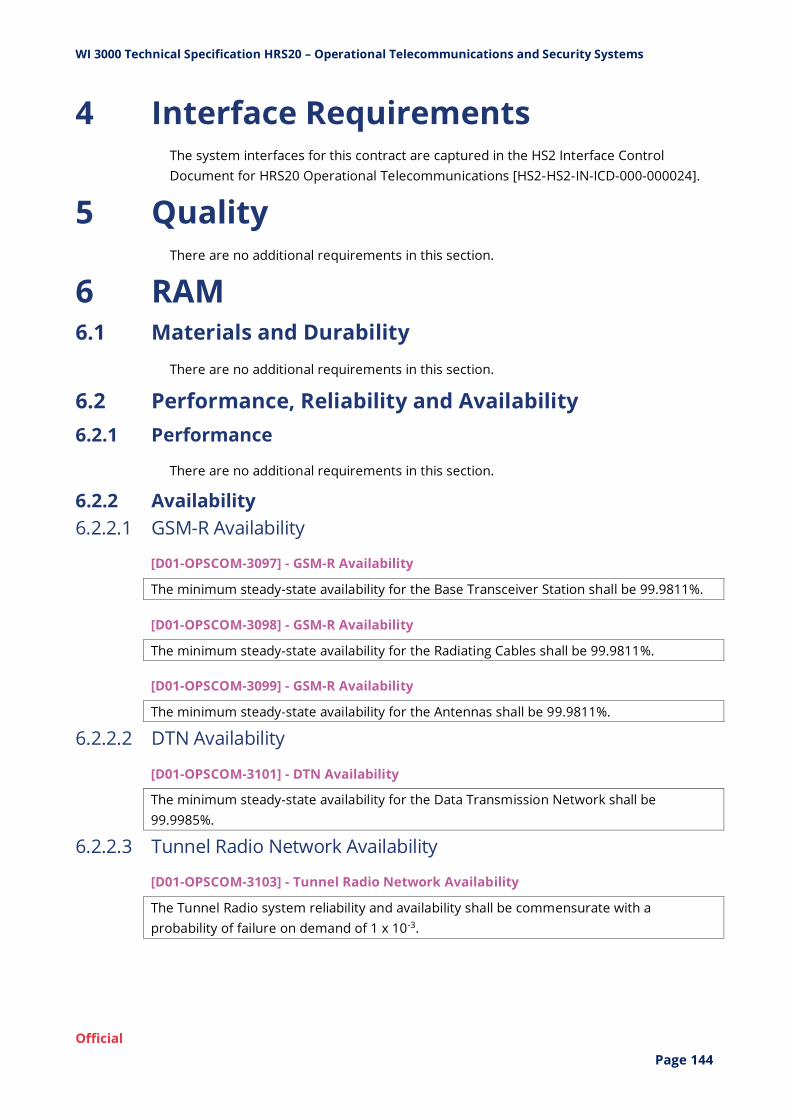
WI 3000 Technical Specification HRS20 – Operational Telecommunications and Security Systems
Official
Page 144
4 Interface Requirements The system interfaces for this contract are captured in the HS2 Interface Control
Document for HRS20 Operational Telecommunications [HS2-HS2-IN-ICD-000-000024].
5 Quality There are no additional requirements in this section.
6 RAM 6.1 Materials and Durability
There are no additional requirements in this section.
6.2 Performance, Reliability and Availability
6.2.1 Performance
There are no additional requirements in this section.
6.2.2 Availability
6.2.2.1 GSM-R Availability
[D01-OPSCOM-3097] - GSM-R Availability
The minimum steady-state availability for the Base Transceiver Station shall be 99.9811%.
[D01-OPSCOM-3098] - GSM-R Availability
The minimum steady-state availability for the Radiating Cables shall be 99.9811%.
[D01-OPSCOM-3099] - GSM-R Availability
The minimum steady-state availability for the Antennas shall be 99.9811%.
6.2.2.2 DTN Availability
[D01-OPSCOM-3101] - DTN Availability
The minimum steady-state availability for the Data Transmission Network shall be
99.9985%.
6.2.2.3 Tunnel Radio Network Availability
[D01-OPSCOM-3103] - Tunnel Radio Network Availability
The Tunnel Radio system reliability and availability shall be commensurate with a
probability of failure on demand of 1 x 10⁻³.
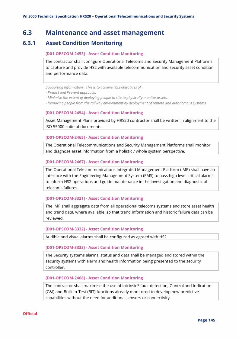
WI 3000 Technical Specification HRS20 – Operational Telecommunications and Security Systems
Official
Page 145
6.3 Maintenance and asset management
6.3.1 Asset Condition Monitoring
[D01-OPSCOM-2453] - Asset Condition Monitoring
The contractor shall configure Operational Telecoms and Security Management Platforms
to capture and provide HS2 with available telecommunication and security asset condition
and performance data.
Supporting Information : This is to achieve HS2 objectives of :
- Predict and Prevent approach.
- Minimise the extent of deploying people to site to physically monitor assets.
- Removing people from the railway environment by deployment of remote and autonomous systems.
[D01-OPSCOM-2454] - Asset Condition Monitoring
Asset Management Plans provided by HRS20 contractor shall be written in alignment to the
ISO 55000 suite of documents.
[D01-OPSCOM-2465] - Asset Condition Monitoring
The Operational Telecommunications and Security Management Platforms shall monitor
and diagnose asset information from a holistic / whole system perspective.
[D01-OPSCOM-2467] - Asset Condition Monitoring
The Operational Telecommunications Integrated Management Platform (IMP) shall have an
interface with the Engineering Management System (EMS) to pass high level critical alarms
to inform HS2 operations and guide maintenance in the investigation and diagnostic of
telecoms failures.
[D01-OPSCOM-3331] - Asset Condition Monitoring
The IMP shall aggregate data from all operational telecoms systems and store asset health
and trend data, where available, so that trend information and historic failure data can be
reviewed.
[D01-OPSCOM-3332] - Asset Condition Monitoring
Audible and visual alarms shall be configured as agreed with HS2.
[D01-OPSCOM-3333] - Asset Condition Monitoring
The Security systems alarms, status and data shall be managed and stored within the
security systems with alarm and health information being presented to the security
controller.
[D01-OPSCOM-2468] - Asset Condition Monitoring
The contractor shall maximise the use of intrinsic* fault detection, Control and Indication
(C&I) and Built-In-Test (BIT) functions already monitored to develop new predictive
capabilities without the need for additional sensors or connectivity.
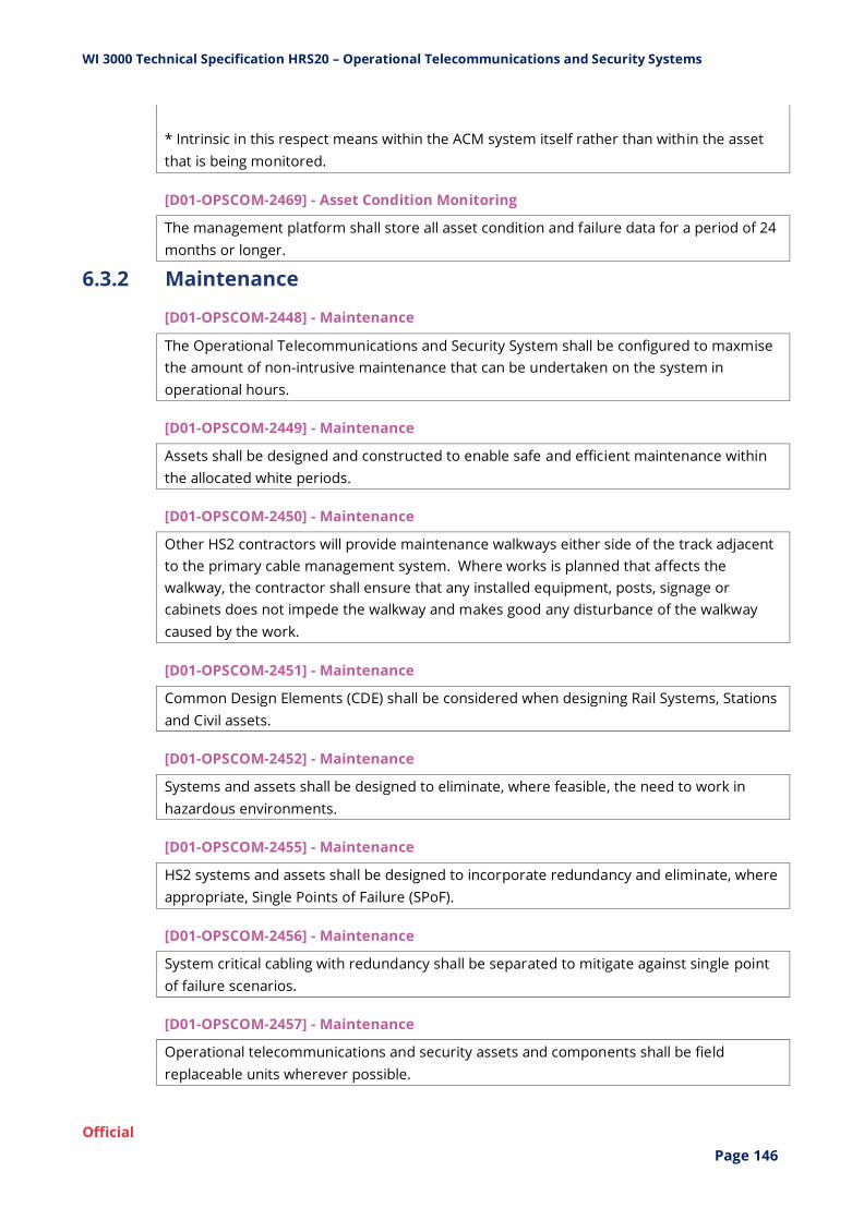
WI 3000 Technical Specification HRS20 – Operational Telecommunications and Security Systems
Official
Page 146
* Intrinsic in this respect means within the ACM system itself rather than within the asset
that is being monitored.
[D01-OPSCOM-2469] - Asset Condition Monitoring
The management platform shall store all asset condition and failure data for a period of 24
months or longer.
6.3.2 Maintenance
[D01-OPSCOM-2448] - Maintenance
The Operational Telecommunications and Security System shall be configured to maxmise
the amount of non-intrusive maintenance that can be undertaken on the system in
operational hours.
[D01-OPSCOM-2449] - Maintenance
Assets shall be designed and constructed to enable safe and efficient maintenance within
the allocated white periods.
[D01-OPSCOM-2450] - Maintenance
Other HS2 contractors will provide maintenance walkways either side of the track adjacent
to the primary cable management system. Where works is planned that affects the
walkway, the contractor shall ensure that any installed equipment, posts, signage or
cabinets does not impede the walkway and makes good any disturbance of the walkway
caused by the work.
[D01-OPSCOM-2451] - Maintenance
Common Design Elements (CDE) shall be considered when designing Rail Systems, Stations
and Civil assets.
[D01-OPSCOM-2452] - Maintenance
Systems and assets shall be designed to eliminate, where feasible, the need to work in
hazardous environments.
[D01-OPSCOM-2455] - Maintenance
HS2 systems and assets shall be designed to incorporate redundancy and eliminate, where
appropriate, Single Points of Failure (SPoF).
[D01-OPSCOM-2456] - Maintenance
System critical cabling with redundancy shall be separated to mitigate against single point
of failure scenarios.
[D01-OPSCOM-2457] - Maintenance
Operational telecommunications and security assets and components shall be field
replaceable units wherever possible.
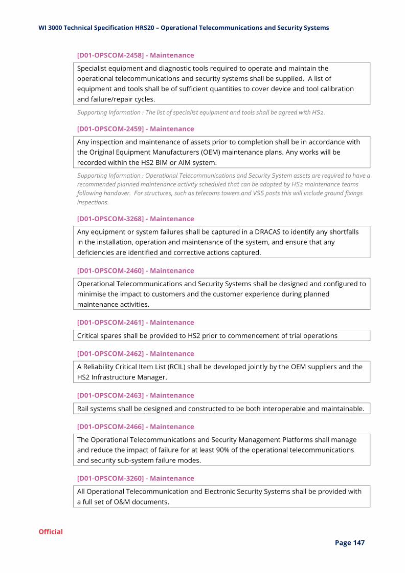
WI 3000 Technical Specification HRS20 – Operational Telecommunications and Security Systems
Official
Page 147
[D01-OPSCOM-2458] - Maintenance
Specialist equipment and diagnostic tools required to operate and maintain the
operational telecommunications and security systems shall be supplied. A list of
equipment and tools shall be of sufficient quantities to cover device and tool calibration
and failure/repair cycles.
Supporting Information : The list of specialist equipment and tools shall be agreed with HS2.
[D01-OPSCOM-2459] - Maintenance
Any inspection and maintenance of assets prior to completion shall be in accordance with
the Original Equipment Manufacturers (OEM) maintenance plans. Any works will be
recorded within the HS2 BIM or AIM system.
Supporting Information : Operational Telecommunications and Security System assets are required to have a
recommended planned maintenance activity scheduled that can be adopted by HS2 maintenance teams
following handover. For structures, such as telecoms towers and VSS posts this will include ground fixings
inspections.
[D01-OPSCOM-3268] - Maintenance
Any equipment or system failures shall be captured in a DRACAS to identify any shortfalls
in the installation, operation and maintenance of the system, and ensure that any
deficiencies are identified and corrective actions captured.
[D01-OPSCOM-2460] - Maintenance
Operational Telecommunications and Security Systems shall be designed and configured to
minimise the impact to customers and the customer experience during planned
maintenance activities.
[D01-OPSCOM-2461] - Maintenance
Critical spares shall be provided to HS2 prior to commencement of trial operations
[D01-OPSCOM-2462] - Maintenance
A Reliability Critical Item List (RCIL) shall be developed jointly by the OEM suppliers and the
HS2 Infrastructure Manager.
[D01-OPSCOM-2463] - Maintenance
Rail systems shall be designed and constructed to be both interoperable and maintainable.
[D01-OPSCOM-2466] - Maintenance
The Operational Telecommunications and Security Management Platforms shall manage
and reduce the impact of failure for at least 90% of the operational telecommunications
and security sub-system failure modes.
[D01-OPSCOM-3260] - Maintenance
All Operational Telecommunication and Electronic Security Systems shall be provided with
a full set of O&M documents.
WI 3000 Technical Specification HRS20 – Operational Telecommunications and Security Systems
Official
Page 148
Supporting Information : The O&M documentation is to include a list of safety hazards and safety
precautions that must be taken by users.
[D01-OPSCOM-3261] - Maintenance
All Operational Telecommunication and Electronic Security Systems shall be provided with
a full set of maintenance specifications for HS2 acceptance.
6.3.3 Obsolescence
[D01-OPSCOM-2464] - Obsolescence
Original Equipment Manufacturer (OEM) suppliers shall provide upgrade paths for supplied
systems in order to mitigate obsolescence risk.
6.3.4 Whole lifecycle cost
There are no additional requirements in this section.
7 Safety [D01-OPSCOM-3273] - Safety
The systems shall comply with the specified system safety targets.
[D01-OPSCOM-3274] - Safety
For all systems performing railway control and protection functions, the safety related
electronic systems for signalling principles contained within BS EN 50129 shall apply.
[D01-OPSCOM-3275] - Safety
For all systems performing railway control and protection functions, the software for
railway control and protection systems principles contained within BS EN 50128 shall apply.
[D01-OPSCOM-3276] - Safety
For all systems performing railway control and protection functions, the systems approach
to safety principles contained within BS EN 50126 Part 2 shall apply.
[D01-OPSCOM-3277] - Safety
The software development tools and process shall be suitably accurate and robust to
reflect the SIL level of the functions being performed by the system.
Supporting Information : The assessed Operational Telecommunication and Security Systems functions at
this stage determined that they shall have a minimum of "Basic Integrity" (see sections 3.2.1, 3.4.1, 3.5.8.8.,
3.6.1, 3.7.1, & 3.9.6.1).
[D01-OPSCOM-3278] - Safety
The Suppliers shall comply with CSM-RA.

WI 3000 Technical Specification HRS20 – Operational Telecommunications and Security Systems
Official
Page 149
[D01-OPSCOM-3279] - Safety
The Safety Cases / safety justifications for the Operational Telecommunication and Security
System shall detail how the the ‘safety’ and ‘non-safety’ parts of the system have been
segregated.
[D01-OPSCOM-3280] - Safety
The Safety Cases / safety justifications for the Operational Telecommunication and Security
System shall detail how the design has minimised the ‘safety’ part of the system.
[D01-OPSCOM-3281] - Safety
The Safety Cases / safety justifications for the Operational Telecommunication and Security
System shall detail how the design has avoided the need for safety-critical parts of the
system.
[D01-OPSCOM-3282] - Safety
The Safety Cases / safety justifications for the Operational Telecommunication and Security
System shall detail how the design has minimised the required safety integrity of each
safety-related part of the system.
[D01-OPSCOM-3283] - Safety
The Safety Cases / safety justifications for the Operational Telecommunication and Security
System shall detail how the design has separated the ‘control’ and ‘protection’ systems.
[D01-OPSCOM-3284] - Safety
The Safety Cases / safety justifications for the Operational Telecommunication and Security
System shall detail how the design has avoided ‘provocation’ (i.e. leaning on the safety
protection).
[D01-OPSCOM-3285] - Safety
The Safety Cases / safety justifications for the Operational Telecommunication and Security
System shall detail how the design has minimised interdependency between parts of the
system.
[D01-OPSCOM-3286] - Safety
The Safety Cases / safety justifications for the Operational Telecommunication and Security
System shall detail how the design has partitioned the system to minimise the number of
interfaces.
[D01-OPSCOM-3287] - Safety
The Safety Cases / safety justifications for the Operational Telecommunication and Security
System shall detail how the design has provided the simplest adequate solution.
WI 3000 Technical Specification HRS20 – Operational Telecommunications and Security Systems
Official
Page 150
[D01-OPSCOM-3288] - Safety
The Safety Cases / safety justifications for the Operational Telecommunication and Security
System shall detail how the design has used the simplest practicable technology.
[D01-OPSCOM-3289] - Safety
The Safety Cases / safety justifications for the Operational Telecommunication and Security
System shall detail how the design has maximised visibility of the safety principles used in
the design and implementation.
[D01-OPSCOM-3290] - Safety
The Safety Cases / safety justifications for the Operational Telecommunication and Security
System shall detail how the design has managed the complexity (e.g. hierarchical levels,
modularity, restricted options).
[D01-OPSCOM-3291] - Safety
The Safety Cases / safety justifications for the Operational Telecommunication and Security
System shall detail how the design has minimised novelty: use existing proven techniques
as far as possible.
[D01-OPSCOM-3292] - Safety
The Safety Cases / safety justifications for the Operational Telecommunication and Security
System shall detail how the design has provided correspondence between functional
entities and physical equipment.
[D01-OPSCOM-3293] - Safety
The Safety Cases / safety justifications for the Operational Telecommunication and Security
System shall detail how the design has partitioned the system to create simple, testable
interfaces.
[D01-OPSCOM-3294] - Safety
The Safety Cases / safety justifications for the Operational Telecommunication and Security
System shall detail how the design has adopted a defined ‘safe state’ under failure
conditions.
[D01-OPSCOM-3295] - Safety
Where possible, the design shall avoid placing absolute reliance for safety on any single
entity, even if claimed to be ‘Fail-Safe’ or ‘Safety Integrity Level (SIL) 4’. (Defence against
systematic failure).
[D01-OPSCOM-3296] - Safety
Diversity shall be applied at the highest practicable level in the system (e.g. separate
control and protection systems would be better than a combined system containing sub-
systems, each of which is individually protected).

WI 3000 Technical Specification HRS20 – Operational Telecommunications and Security Systems
Official
Page 151
8 Fire Safety [D01-OPSCOM-3319] - Fire Safety
Travel distances within the buildings shall be limited to the limits given in BS 9999/BS 9992
for the given Risk Profile.
Exceptions are buildings accommodating rolling stock which will need to be separately
assessed and designed in accordance with BS 9999/BS 9992 and BS 7974.
Acceptance criterion: Fire strategies articulating what will be provided; self assured by Contractor's
competent fire engineer and accepted by HS2 and not objected to by the FRS.
Fire safety reports identifying how the requirement have been met and verification by the Contractor
that those measures have been delivered on site.
[D01-OPSCOM-2430] - Fire Safety
All Operational Telecoms and Security Systems REBs shall be provided with an analogue,
addressable fire detection and alarm system designed to the requirements of BS 5839-1
for a category P1/M system.
Acceptance criterion: Fire strategies articulating what will be provided; self-assured by Contractor's
competent fire engineer and accepted by HS2 and not objected to by the FRS.
Fire safety report identifying how the requirement has been met and verification by the Contractor that
those measures have been delivered on site including testing, commissioning and handover
documentations.
Regular site audits by Contractor's competent fire engineer and ad-hoc audits by HS2.
HS2 and FRS attendance at agreed witness testing.
Handover documentation submission to HS2 in accordance with BS 5839.
[D01-OPSCOM-2431] - Fire Safety
All Operational Telecoms and Security Systems REBs shall be provided with and automatic
fire detection system and with a manual fire alarm call point.
Acceptance criterion: Fire strategies articulating what will be provided; self-assured by Contractor's
competent fire engineer and accepted by HS2 and not objected to by the FRS.
Fire safety reports identifying how the requirements have been met and verification by the Contractor
that those measures have been delivered on site.
Regular site audits by Contractor's competent fire engineer and ad-hoc audits by HS2.
[D01-OPSCOM-2432] - Fire Safety
Manual fire alarm call points shall be located at every exit to fresh air in accordance with BS
5839 Part 1.
Acceptance criterion: Fire strategies articulating what will be provided; self-assured by Contractor's
competent fire engineer and accepted by HS2 and not objected to by the FRS.
Fire safety report identifying how the requirements have been met and verification by the Contractor
that those measures have been delivered on site including testing, commissioning and handover
documentations.
Regular site audits by Contractor's competent fire engineer and ad-hoc audits by HS2. HS2 and FRS
attendance at agreed witness testing.
HS2 and FRS attendance at agreed witness testing.
Handover documentation submission to HS2 in accordance with BS 5839.

WI 3000 Technical Specification HRS20 – Operational Telecommunications and Security Systems
Official
Page 152
[D01-OPSCOM-2433] - Fire Safety
All smoke detectors shall comply with BS EN 54 Part 7, while heat detectors shall comply
with BS EN 54 Part 5.
Acceptance criterion: Fire strategies articulating what will be provided; self-assured by Contractor's
competent fire engineer and accepted by HS2 and not objected to by the FRS.
Fire safety reports identifying how the requirements have been met and verification by the Contractor
that those measures have been delivered on site.
Regular site audits by Contractor's competent fire engineer and ad-hoc audits by HS2.
[D01-OPSCOM-2434] - Fire Safety
The REB fire alarm system shall monitor fire alarm status, incoming power supply status
and system health. These alarms presented to the HS2 Infrastructure Controller at the
NICC.
Supporting Information : The alarms are connected to the HS2 Engineering Management System (EMS) via:-
- HRS03 Power SCADA system in Railway System Compounds, and
- HRS02 M&E SCADA at Radio Mast Compounds/Rapid Deployment Sites
Acceptance criterion: Fire strategies articulating what will be provided; self-assured by Contractor's
competent fire engineer and accepted by HS2 and not objected to by the FRS.
Fire safety reports identifying how the requirements have been met and verification by the Contractor
that those measures have been delivered on site including end to end integrated tests.
Regular site audits by Contractor's competent fire engineer and ad-hoc audits by HS2.
[D01-OPSCOM-2435] - Fire Safety
Fire rated cables shall comply with BS 8519, Selection and installation of fire-resistant
power and control cable systems for life safety and fire-fighting applications, Code of
practice and be rated in accordance with BS 8491, Method for assessment of fire integrity
of large diameter power cables for use as components for smoke and heat control systems
and certain other active fire safety systems or BS EN 50200, Method of test for resistance
to fire of unprotected small cables for use in emergency circuits, (depending on diameter)
categories C, W and category F2 for performance under fire conditions.
Acceptance criterion: Self certification demonstrating that the BSs have been complied with.
Regular site audits by Contractor's competent fire engineer and reviews and acceptance of designs and
ad-hoc site audits by HS2.
[D01-OPSCOM-2436] - Fire Safety
Cable fixings carrying fire rated cables shall provide adequate support in the presence of a
fire to not compromise the fire performance of any cable.
Acceptance criterion: Evidence that the materials meet this requirement including fire test reports and
fire test certificates.
Regular site audits by Contractor's competent fire engineer and reviews and acceptance of designs and
ad-hoc site audits by HS2.
[D01-OPSCOM-2437] - Fire Safety
Cable fixings and supports carrying fire rated cables shall be designed to cater for the
reduction in the tensile strength of steel when exposed to the effects of fire in accordance
with BS 8519.

WI 3000 Technical Specification HRS20 – Operational Telecommunications and Security Systems
Official
Page 153
Acceptance criterion: Self certification demonstrating that the BS has been complied with.
Regular site audits by Contractor's competent fire engineer and reviews and acceptance of designs and
ad-hoc site audits by HS2.
[D01-OPSCOM-2438] - Fire Safety
Cables within tunnels shall satisfy the characteristics of low flammability, low fire spread,
low toxicity and low smoke density in accordance with NTSN for Safety in Rail Tunnels.
These requirements shall be fulfilled when cables as a minimum have:
- A classification of B2ca-S1a, d0, a1 as per BS EN 13501-6, Classification using data from
reaction to fire tests on electric cables.
- A toxicity index (ITC) less than 10, as for exterior cables in accordance with BS EN 45545-2
Railways applications – Fire protection on railway vehicles. Part 2: Requirements for fire
behaviour of materials and components.
Acceptance criterion: Self certification demonstrating that the requirement has been met.
Regular site audits by Contractor's competent fire engineer and reviews and acceptance of designs and
ad-hoc site audits by HS2.
[D01-OPSCOM-2439] - Fire Safety
Construction materials and installations within tunnels shall have low flammability and
fulfil the reaction requirements of NTSN for Safety in Rail Tunnels.
Acceptance criterion: Evidence that the materials meet this requirement including fire test reports and
fire test certificates of the materials and installation system provided.
Regular site audits by Contractor's competent fire engineer and reviews and acceptance of designs and
ad-hoc site audits by HS2.
[D01-OPSCOM-2440] - Fire Safety
For areas not covered under the NTSN for Safety in Rail Tunnels, materials shall be as
defined in BS 9999/BS 9992.
Acceptance criterion: Self certification demonstrating that the BS has been complied with.
Evidence that the materials meet this requirement including fire test reports and fire test certificates of
the materials and installation system provided.
Regular site audits by Contractor's competent fire engineer and reviews and acceptance of designs and
ad-hoc site audits by HS2.
[D01-OPSCOM-2441] - Fire Safety
Operational Telecommunications and Security systems installed within tunnels (except
light diffusers and cables) shall comply with BS EN 45545-2 R23 classification with LOI >
28% (UL94 V0 will also be accepted for the relevant thickness of material), Ds(max) < 600
and CIT < 1.8.
Acceptance criterion: Self certification demonstrating that the BS has been complied with.
Evidence that the materials meet this requirement including fire test reports and fire test certificates of
the materials and installation system provided.
Regular site audits by Contractor's competent fire engineer and reviews and acceptance of designs and
ad-hoc site audits by HS2.
WI 3000 Technical Specification HRS20 – Operational Telecommunications and Security Systems
Official
Page 154
[D01-OPSCOM-2442] - Fire Safety
Fire stopping shall be provided for all services penetrations where required to maintain fire
compartmentation in accordance with BS 9999/BS 9992.
Acceptance criterion: Self certification demonstrating that the BS has been complied with including fire
test reports and fire test certificates of the materials and installation system used.
Regular site audits by Contractor's competent fire engineer and reviews and acceptance of designs and
ad-hoc site audits by HS2.
[D01-OPSCOM-2443] - Fire Safety
Emergency signage shall be provided in all buildings in accordance with BS 5499 Parts 4
and 10.
Acceptance criterion: Self certification demonstrating that the BS has been complied with.
Electrically powered emergency signage to be tested, commissioned and handed over in line with the
requirements for emergency lighting. Regular site audits by Contractor's competent fire engineer and
ad-hoc audits by HS2.
[D01-OPSCOM-2444] - Fire Safety
In Tunnels a fixed emergency telephone shall be provided at each cross passage door
location to allow direct communications between the Emergency Services or user and
NICC.
Acceptance criterion: Evidence that safe areas have been provided to meet this requirement. Self-
assured by Contractor's competent fire engineer and accepted by HS2.
9 Security 9.1 Physical Security
[D01-OPSCOM-2424] - Physical Security
The HS2 network shall be designed in accordance with Technical Standard - Station and
Network-Wide Security [HS2-HS2-AR-STD-000-000003].
Supporting Information : The HS2 network includes stations, rolling stock storage and maintenance areas,
Network Integrated Control Centre, the railway, trackside infrastructure and other fixed installations.
The HS2 network will be protected by perimeter fencing in accordance with HS2 Technical Standard –
Station and Network-Wide Security HS2-HS2-AR-STD-000-000003 and determined on a risk based
approach.
Acceptance criterion: Compliance successfully verified by witnessed demonstration of functioning
equipment on site accompanied with documented results.
[D01-OPSCOM-2425] - Physical Security
REBs, equipment cabinets or cages located in a Low or Medium risk area shall comply with
LPS 1175 SECURITY RATINGS SR2
Acceptance criterion: Compliance successfully verified by witnessed demonstration of functioning
equipment on site accompanied with documented results.

WI 3000 Technical Specification HRS20 – Operational Telecommunications and Security Systems
Official
Page 155
[D01-OPSCOM-2426] - Physical Security
REBs, equipment cabinets or cages located in a High risk area shall comply with LPS 1175
SECURITY RATINGS SR3.
Acceptance criterion: Compliance successfully verified by witnessed demonstration of functioning
equipment on site accompanied with documented results.
[D01-OPSCOM-2427] - Physical Security
All Operational Telecommunications and Security Systems equipment shall be installed
within the secure perimeter of the line-side security fence or within a secure compound.
Acceptance criterion: Compliance successfully verified by witnessed inspection of capability
accompanied with documented results.
[D01-OPSCOM-2428] - Physical Security
For Operational Telecommunications and Security Systems equipment to be installed
outside of a secure area, the Contractor shall undertake a Threat and Vulnerability Risk
Assessment (TVRA) as described in Technical Standard - Station and Network-Wide Security
[HS2-HS2-AR-STD-000-000003] to determine the security measures required at that
location.
Acceptance criterion: Compliance successfully verified by witnessed demonstration of functioning
equipment on site accompanied with documented results.
[D01-OPSCOM-3318] - Physical Security
Operational Telecommunications and Security System REBs and cabinets shall be designed
and constructed to prevent unauthorised access and theft and/or unlawful removal of
assets and equipment.
9.2 Cyber Security
[D01-OPSCOM-2835] - Cyber Security
The Operational Telephony, Electronic Security Systems, Fire Ground Radio and GSM-R sub-
systems of the Operational Telecommunications shall comply with IEC 62443 Part 3-3
Security Level 1 (SL1)
Supporting Information : The key drivers for Security Level 1 on the Operational Telecommunications sub-
systems (Operational Telephony, Electronic Security Systems, Fire Ground Radio and GSM-R) is the
protection provided by the DTN architecture, the threat actors being Insiders, no safety critical implication
and limited availability impact.
Acceptance criterion: Compliance statement from the Contractor that all the requirements within the
62443-3-3 Standard at Security Level 1 have been met. Also, evidence from the Contractor showing
how each requirement within the 62443-3-3 Standard at Security Level 1 has been achieved.
Identification and justification from the Contractor of any requirement that has not been met or only
partially met.
[D01-OPSCOM-2836] - Cyber Security
The Data Transmission Network sub-system of the Operational Telecommunications shall
comply with IEC 62443 Part 3-3 Security Level 2 (SL2)

WI 3000 Technical Specification HRS20 – Operational Telecommunications and Security Systems
Official
Page 156
Supporting Information : The key drivers for Security Level 2 on following Operational Telecommunications
sub-system (Data Transmission Network) is the importance of the DTN to all HS2 operational systems (both
control systems and non-control systems), the DTN cyber security architecture (zoning), no safety critical
implication and the possible impact on availability.
Acceptance criterion: Compliance statement from the Contractor that all the requirements within the
62443-3-3 Standard at Security Level 2 have been met. Also, evidence from the Contractor showing
how each requirement within the 62443-3-3 Standard at Security Level 2 has been achieved.
Identification and justification from the Contractor of any requirement that has not been met or only
partially met.
[D01-OPSCOM-2837] - Cyber Security
The System shall comply with the Cyber Security Technical Standard [HS2-HS2-EN-STD-000-
000011].
Supporting Information : The security requirements for the identified Security Level are listed within an
appendix of the Cyber Security Technical Standard (Ref : HS2-HS2-EN-STD-000-000011).
Acceptance criterion: Compliance statement from the Contractor that all the requirements within the
Cyber Security Technical Standard have been met. Also evidence from the Contractor showing how
each requirement within the Technical Standard has been achieved. Identification and justification
from the Contractor of any requirement that has not been met or only partially met.
10 Environment and Sustainability [D01-OPSCOM-2471] - Environment and Sustainability
Operational Telecommunication and Security Systems shall be designed, supplied and
installed to be resilient to the effects of climate change over the life of the asset.
Supporting Information : Where appropriate, climate change adaptation and resilience requirements are
embedded into relevant engineering and other Technical Standards and this Works Information. The HS2 Ltd
Climate Change Adaptation and Resilience Technical Standard [HS2-HS2-SU-STD-000-000003], sets out a
process for managing climate change adaptation and resilience. The Climate Change Adaptation and
Resilience Technical Standard is underpinned by two key assessments:
. The Climate Change Design Impact Assessment (CCDIA) [HS2-HS2-EV-REP-000-000023], provides an
assessment of the resilience of HS2 to future climate change.
. The Climate Change Resilience and Interdependencies Assessment (CCRIA) [HS2‐ HS2‐EV‐REP‐000‐
000010] is an assessment of interdependencies of HS2 that may be affected by climate change.
Acceptance criterion: The CCDIA shall be reviewed at every Contract Stage (see WI300) by the
Contractor in order to consider the impacts of climate change related to their Works. The Contractor
shall also review the CCRIA at every Contract Stage (see WI300), in order to consider the impacts of
climate change on interdependencies related to the Works. The designer shall evidence each review of
the CCDIA and CCRIA through a Climate Change Adaptation and Resilience Report (CCARR).
[D01-OPSCOM-2472] - Environment and Sustainability
Unless essential for safety purposes, there shall be no artificial lighting provision on the
green bridge, and also no artificial lighting provision where light could spill onto the flight
path of bats, either on the bridge or on the approaches to the bridge.

WI 3000 Technical Specification HRS20 – Operational Telecommunications and Security Systems
Official
Page 157
[D01-OPSCOM-2939] - Environment and Sustainability
Where a culvert is intended to maintain a bat commuting route and where there is a risk of
light spillage from the railway onto the culvert entrance of flight approaches, close boarded
fencing shall be used.
Supporting Information : Requirement applies to contracts having scope of work delivered in proximity of
wildlife culverts used as a suitable route for passage of target species such as bats. The location of such
culverts is determined in the design submitted by the Main Work Civils contractors.
This information on culverts location is to be provided by HS2 to the contractor through Building Information
Models when available.
[D01-OPSCOM-2940] - Environment and Sustainability
Culverts shall be unlit and there shall be a designated dark area (maximum 0.5 lux) within
50 m of the entrance to the culverts.
Supporting Information : Requirement applies to contracts having scope of work delivered in proximity of
wildlife culverts used as a suitable route for passage of target species such as bats. The location of such
culverts is determined in the design submitted by the Main Work Civils contractors.
This information on culverts location is to be provided by HS2 to the contractor through Building Information
Models when available.
[D01-OPSCOM-2941] - Environment and Sustainability
Where artificial lighting is required within 50m of the entrance to the culverts for health
and safety reasons, it shall only operate on a motion triggered basis.
Supporting Information : Requirement applies to contracts having scope of work delivered in proximity of
wildlife culverts used as a suitable route for passage of target species such as bats. The location of such
culverts is determined in the design submitted by the Main Work Civils contractors.
This information on culverts location is to be provided by HS2 to the contractor through Building Information
Models when available.
[D01-OPSCOM-2942] - Environment and Sustainability
The motion triggers for artificial lighting within 50m of the entrance to the culverts shall be
designed to ensure they are not triggered by the species utilising the culvert.
Supporting Information : Requirement applies to contracts having scope of work delivered in proximity of
wildlife culverts used as a suitable route for passage of target species such as bats. The location of such
culverts is determined in the design submitted by the Main Work Civils contractors.
This information on culverts location is to be provided by HS2 to the contractor through Building Information
Models when available.
[D01-OPSCOM-2943] - Environment and Sustainability
Light levels in areas where close-boarded fencing has been used to provide mitigation for
bats, post construction shall not exceed 0.5 lux compared to pre-construction levels.
Supporting Information : Requirement applies to contracts having scope of work delivered in proximity of
wildlife culverts used as a suitable route for passage of target species such as bats. The location of such
culverts is determined in the design submitted by the Main Work Civils contractors.
This information on culverts location is to be provided by HS2 to the contractor through Building Information
Models when available.
WI 3000 Technical Specification HRS20 – Operational Telecommunications and Security Systems
Official
Page 158
11 Interoperability There are no additional requirements in this section.
12 Ergonomics [D01-OPSCOM-2480] - Ergonomics
The system shall be designed and constructed so that the users maintain situational
awareness of the status of the system during normal, abnormal, degraded and emergency
conditions.
Supporting Information : Scheme Design - Approved Design Documentation
Detailed Design - Approved Design Documentation / Testing (with representative Users) of the systems to
demonstrate that the design has been implemented as designed.
Construction & Handover - Testing (User)
Acceptance criterion: Evidence that the system is has been developed to optimise the allocation of
functions between the users and the system in order to optimise user situational awareness and
reduce the opportunity for Human / Use Error to ALARP whilst maintaining the required level of
system performance.
To be submitted to and accepted by the HS2 EAM.
Submissions required at Scheme Design, Detailed Design, Construction & Handover.
[D01-OPSCOM-2481] - Ergonomics
The system shall be designed and constructed to remove or reduce to ALARP the risk of
Human / Use Error.
Supporting Information : The term 'Use Error' has been explicitly utilised as it infers that accidents / incident
should be attributed to the circumstances and the design of the system / equipment being utilised, rather
than apportioning blame to the human beings interacting with the system. As such the design of the system
is critical.
Scheme Design - Approved Design Documentation
Detailed Design - Approved Design Documentation / Testing (User)
Construction & Handover - Testing (User)
Acceptance criterion: Ergonomics Plan (or separate referenced paper) defining the approach to be
applied to model and address Human / User Error and reduce identified issues to ALARP.
Evidence that the system is designed and built to eliminate or reduce to ALARP the risk of Human /
User Error during maintenance including mis-assembly / re-assembly tasks.
To be submitted to and accepted by the HS2 EAM.
Submissions required at Scheme Design, Detailed Design, Construction & Handover.

WI 3000 Technical Specification HRS20 – Operational Telecommunications and Security Systems
Official
Page 159
[D01-OPSCOM-2482] - Ergonomics
The system shall be designed to be error tolerant
Supporting Information : Error tolerant systems are designed such a way that should the user commit an
error when using the system it will not lead to an unsafe event. Typically error tolerant systems remove
opportunities for error to occur. E.g. a system is designed so that it can only be assembled one way and items
cannot be installed back-to-front or upside down.
Acceptance criterion: Ergonomics Plan (or separate referenced paper) defining the approach to be
applied to model and address Human . User Error and reduce identified issues to ALARP.
Evidence of testing that the system is error tolerant eliminates or reduces to ALARP the risk of Human /
User Error during maintenance including mis-assembly / re-assembly task.
To be submitted to and accepted by the HS2 EAM.
Submissions required at Scheme Design, Detailed Design, Construction & Handover.
[D01-OPSCOM-2483] - Ergonomics
The system shall be designed and constructed so that the users cognitive and physical
workload is acceptable.
Supporting Information : Scheme Design - Approved Design Documentation
Detailed Design - Approved Design Documentation / Testing (with representative Users) of the systems to
demonstrate that the design has been implemented as designed.
Construction & Handover - Testing (User)
Typically, this would be achieved through:
1. Physical Workload assessment of relevant tasks associated with system and identification of issues.
2. Cognitive Workload Assessment of system / subsystems and identification of issues.
Acceptance criterion: 1. The methodology to assess users cognitive / physical workload for the system
is defined by the contractor and approved by HS2.
2. The criteria for acceptable workload is defined by the contractor and agreed by HS2 (this will depend
on the model used by the contractor). Historically Task Occupancy has been used as a measure of
workload and typically levels below 60% are deemed acceptable with sufficient spare capability to deal
with and address abnormal, emergency and degraded events.
3. Workload Assessment of system / subsystems during normal modes of operation and identification
of issues.
4. Workload Assessment of typical (and agreed) abnormal, degraded and emergency conditions
events.
5. Evidence that output from workload assessment is embedded in design of system. 3. Evidence that
the system is has been developed to optimise the level of cognitive & physical workload. Initially
through design this will be through a predictive assessment that will feed into the design. This will then
be modelled and tested on a prototype before being tested and demonstrated on the installed system
prior to commissioning.

WI 3000 Technical Specification HRS20 – Operational Telecommunications and Security Systems
Official
Page 160
[D01-OPSCOM-2484] - Ergonomics
The system shall be designed and constructed so that the user has sufficient cognitive
spare capacity during normal scenarios to safely manage and address unplanned events
(abnormal, degraded and emergency conditions).
Supporting Information : This requirement is based on ensuring that the system is designed for normal modes
of operations (and thus is cost effective) but takes into account that a user cannot operate at 100% workload
capacity. As such the system should be designed so that during normal modes of operation the user will
have adequate spare cognitive and physical workload capacity to address unplanned or abnormal events for
short periods of time.
Acceptance criterion: 1. Definition of acceptable workload spare capacity in line with railway good
practice (typically based on task occupancy - however contractor to define).
2. Workload Assessment of system / subsystems during normal modes of operation and identification
of issues.
3. Workload Assessment of typical (and agreed) abnormal, degraded and emergency conditions events.
4. Evidence that output from workload assessment is embedded in design of system.
[D01-OPSCOM-2485] - Ergonomics
The system shall be designed and constructed so that it can be maintained and operated
safely by a 5th percentile female to a 95th percentile male user.
Supporting Information : Contractors output should demonstrate progressively that the system can be
operated / maintained by all identified users as defined by contractor using the HS2 User Profile proformas.
<Peoplesize2008> is used as the baseline anthropometric dataset.
<Adultdata> is the baseline human strength dataset.
The requirement should take into account any special Personal Protective Equipment of clothing used by the
operator.
Scheme Design - Approved Design Documentation
Detailed Design - Approved Design Documentation / Testing (User)
Construction & Handover - Testing (User).
Acceptance criterion: Evidence that the system is designed and constructed to support 5th percentile
female through to 95th percentile male users for all relevant anthropometric and strength
characteristics including secular growth using:
<Peoplesize2008> for anthropometric dataset.
<Adultdata> for human strength dataset.
User Profiles - identification of the users
Key Anthropometric parameters and dimensions identified for each user.
Evidence that key anthropometric data has been embedded into the design or selection of the system
/ sub-system / equipment.
WI 3000 Technical Specification HRS20 – Operational Telecommunications and Security Systems
Official
Page 161
To be submitted to and accepted by the HS2 EAM.
Submission at Scheme Design, Detailed Design, Construction & Handover.
[D01-OPSCOM-2486] - Ergonomics
The system will be designed to take into account user secular growth of users throughout
its design life.
Supporting Information : <Peoplesize2008> is used as the baseline anthropometric dataset.
If secular growth is not taken into account the system design will become redundant throughout its life.
Acceptance criterion: Evidence that anthropodermic data has been scaled appropriately to take into
account service life of the system / sub-systems / equipment.
[D01-OPSCOM-2487] - Ergonomics
The contractor will identify and document the critical anthropometric characteristics for
each user that they have identified for each system and associated sub-systems /
equipment.
[D01-OPSCOM-2488] - Ergonomics
The contractor will utilise <Peoplesize 2008> for all anthropometric data associated with
the maintenance and operation of the system.
Where <Peoplesize 2008> does not contain the relevant data the contractor shall propose
an alternative data source and present this for acceptance by the HS2 Ergonomic
Assurance Manager (EAM).
[D01-OPSCOM-2489] - Ergonomics
The system shall be designed and constructed to minimise the risk of musculoskeletal
disorders to ALARP for all users ranging from a 5th percentile female through to a 95th
percentile male user.
Supporting Information : Contractors output should demonstrate progressively that the system can be
operated / maintained by all identified users as defined by contractor using the HS2 User Profile proformas.
The requirement should take into account any special Personal Protective Equipment of clothing used by the
operator.
Scheme Design - Approved Design Documentation
Detailed Design - Approved Design Documentation / Testing (User)
Construction & Handover - Testing (User).
Acceptance criterion:
Evidence that the system is designed and constructed to minimise the risk of muscular skeletal
disorders to ALARP for all users ranging from a 5th percentile female through to a 95th percentile
male user.
WI 3000 Technical Specification HRS20 – Operational Telecommunications and Security Systems
Official
Page 162
Provide definition of assessment methodology to be applied to assess postures for all tasks and ensure
and evidence that the approach aligns with HSE recommended practices. E.g. Rapid Upper Limb
Assessment (RULA) Tool.
To be submitted to and accepted by the HS2 EAM.
Submission at Scheme Design, Detailed Design, Construction & Handover.
[D01-OPSCOM-2490] - Ergonomics
The contractor will identify and document the strength characteristics for each user and
the tasks that they perform for each system and associated sub-systems / equipment.
[D01-OPSCOM-2491] - Ergonomics
The contractor will utilise <AdultData> for all strength data associated with the tasks and
systems / equipment for the maintenance of the system.
Where <AdultData> does not contain the relevant strength data the contractor shall
propose a suitable data source for review and acceptance by the HS2 EAM.
[D01-OPSCOM-2492] - Ergonomics
The contractor will identify the viable environmental conditions in which the users will
operate / maintain the system and the associated constraints such as personal protective
equipment that will impact their ability to perform the various tasks.
This shall include but not be limited to the following environmental parameters.
illumination; climate; noise, and; motion.
[D01-OPSCOM-2493] - Ergonomics
On a progressive basis the contractor will identify all supporting equipment required to
maintain the system and ensure that the user can safely transport the equipment to the
maintenance location and that appropriate measures are in place to support transfer - for
example safe walking routes.
This shall include but not be limited to the following environmental parameters.
illumination; climate; noise, and; motion, limiting level changes and making the quickest
method the safest method
[D01-OPSCOM-2494] - Ergonomics
The system shall be developed and designed to remove or reduce to ALARP the need for
working at height.
Acceptance criterion: Evidence that the design has been developed and assessed to remove the need
to work at height for all required maintenance (and operational) tasks in accordance with the UK
Legislation: Working at Height Regulations (WAHR).
Where it is not possible to remove the need for working at height, evidence shall be provided that the
system has been designed with control measures that reduce the risk to the user to ALARP for working
at height activities.
WI 3000 Technical Specification HRS20 – Operational Telecommunications and Security Systems
Official
Page 163
To be submitted to and accepted by the HS2 EAM.
Submission at Scheme Design, Detailed Design, Construction & Handover.
[D01-OPSCOM-2495] - Ergonomics
The contractor shall support the lead contractors in their Human Factors activities to
design and develop consistent and intuitive Human System Interfaces (HSI) at depots, NICC,
Remote Tap-In Facility and stations by providing design, configuration and documentation
for Operational Telecommunications system end devices.
Supporting Information : The Human System Interface (HSI) is any element of a system, equipment or
product that a user interacts with in order to operate or use the of a system, equipment or product.
The interface consists of hardware and software that allow user inputs to be translated as signals for
machines that, in turn, provide the required result to the user.
Human System Interface are also known as Human Machine Interface (HMI) or Man-Machine interface
(MMI), or Human Computer Interface (HCI).
This requirement is applicable for all HSI's including fixed (for example TMS workstations) and portable
assets (mobile diagnostic device).
Acceptance criterion: 1. Evidence that:
- the HSI for each system has been identified.
- a methodology / approach for the design and development of consistent and intuitive HSI has been
developed
- the HSI for each system has been designed support the needs of the users using the defined
methodology.
- the systems HSIs have been developed in accordance with the <HS2 HSI Style Guide>.
- the design has been tested and evaluated using end user representatives.
- issues raised have been addressed and embedded in the design.
Submission at Scheme Design, Detailed Design, Construction & Handover.
To be submitted to and accepted by the HS2 EAM.
[D01-OPSCOM-2496] - Ergonomics
The contractor shall design and develop the Integrated Management Platform and Security
Management Systems to provide consistent and intuitive Human System Interfaces (HSI)
within the scope of commercially available systems telecoms and security systems.
Supporting Information : The Human System Interface (HSI) is any element of a system, equipment or
product that a user interacts with in order to operate or use the of a system, equipment or product.
The interface consists of hardware and software that allow user inputs to be translated as signals for
machines that, in turn, provide the required result to the user.
Human System Interface are also known as Human Machine Interface (HMI) or Man-Machine interface
(MMI), or Human Computer Interface (HCI).

WI 3000 Technical Specification HRS20 – Operational Telecommunications and Security Systems
Official
Page 164
This requirement is applicable for all HSI's including fixed (for example TMS workstations) and portable
assets (mobile diagnostic device).
Acceptance criterion: 1. Evidence that:
- the HSI for each system has been identified.
- a methodology / approach for the design and development of consistent and intuitive HSI has been
developed
- the HSI for each system has been designed support the needs of the users using the defined
methodology.
- the systems HSIs have been developed in accordance with the <HS2 HSI Style Guide>.
- the design has been tested and evaluated using end user representatives.
- issues raised have been addressed and embedded in the design.
Submission at Scheme Design, Detailed Design, Construction & Handover.
To be submitted to and accepted by the HS2 EAM.
[D01-OPSCOM-2497] - Ergonomics
The usability of the system shall be acceptable to the user(s) as represented by HS2.
Supporting Information : The usability of the system and devices used to support the operation /
maintenance of the system shall be acceptable for the users based on the user goals to be achieved and the
environment in which they are performed.
The HS2 Usability parameters are defined as:
- Effectiveness: The completeness and accuracy with which users achieve specified goals and objectives.
- Error tolerance: The system prevent errors caused by the user's interaction, and to help the user in
recovering from any errors that do occur
- Efficiency: The speed (with accuracy) with which users can complete the tasks
- Satisfaction: The Human System Interface is engaging, if it is pleasant and satisfying to use.
- Ease of Learning - A Human System Interface which is easy to learn allows users to build on their
knowledge without deliberate effort
Acceptance criterion: 1. Evidence of an agreed methodology for conducting usability assessment of the
system and that the usability of the system has been tested and demonstrated as acceptable for
representative users, using but not limited to the following parameters:
- Effectiveness
- Error tolerance
- Efficiency
- Satisfaction
- Ease of Learning
Submission at Scheme Design, Detailed Design, Construction & Handover.
To be submitted to and accepted by the HS2 EAM.
[D01-OPSCOM-2498] - Ergonomics
The system shall be designed and developed to provide consistent, applicable and non-
conflicting alarms and alerts.

WI 3000 Technical Specification HRS20 – Operational Telecommunications and Security Systems
Official
Page 165
Supporting Information : The methodology / approach to address these requirements shall be defined within
the contractors Ergonomics Plan.
Contractors response should demonstrate progressively throughout the lifecycle that the alerts and alarm
presentation for system user interfaces are consistent, reduce Human / Use Error and align with the approach
defined within the <HS2 Alarms Philosophy> and the contractor developed Alarms Strategy to ensure
consistency of user interface and minimise the training impact.
Testing and evaluation will utilise end user representatives.
Where the system is a COTS or third part product the contractor will evaluate the third party products
against the <HS2 Alarm Management Philosophy> to identify and resolve shortfalls and any associated
issues and risks.
Acceptance criterion: 1. Evidence of a work package specific Alerts and Alarms Strategy.
2. Evidence that systems alarms and alerts have been developed in accordance with the <HS2 Alarm
Management Philosophy> and the work package specific Alarms Strategy including:
3. Rationalisation of alert / alarms based on users goals.
4. Consistent alert/alarm presentation across sub-systems / equipment to remove conflicting alerts /
alarms.
To be submitted to and accepted by the HS2 EAM.
Submission at Scheme Design, Detailed Design, Construction & Handover.
13 Sound, Noise and Vibration Early design assumptions concerning the operational sound generated by stationary
systems are provided in the Stationary Systems Sound and Noise Assessment
Assumptions Technical Note (HRS08-WSP-EV-NOT-000-000005). The responsibility for
the risk of any differences between these assumptions and the actual operational
sound generated by stationary systems is transferred to the Contractor.
[D01-OPSCOM-3073] - Sound, Noise and Vibration
The Operational Telecommunications and Security System emissions of airborne sound
shall comply with the stationary systems acoustic design objectives set out in HS2 Phase 1
Information Paper E22 Control of noise from the operation of stationary systems [LWM-
HS2-HY-PPR-000-000056] or HS2 Phase 2a Information Paper E11 Control of noise from the
operation of stationary systems [P2A-HS2-HY-PPR-000-000122] as applicable.
Supporting Information : Relevant HS2 guidance and standards include (but may not be limited to):
- HS2-HS2-EN-STD-000-000003 (design and specification of civil engineering mitigation for noise)
- HS2-HS2-EN-STD-000-000004 (baseline sound survey analysis, stationary systems airborne sound
prediction, assessment, mitigation design and demonstration that sound has been reduced AFARP)
- HS2-HS2-EN-STD-000-000006 (the approach to acoustic design of depots, as applicable)
- HS2-HS2-EN-STD-000-000009 (baseline sound survey monitoring equipment and techniques)
- Planning Forum Note 10 (indicative mitigation)
- Planning Forum Note 12 (engagement with statutory consultees)
- HRS08-WSP-EV-NOT-000-000005 (record of technical assumptions made during the design development)
WI 3000 Technical Specification HRS20 – Operational Telecommunications and Security Systems
Official
Page 166
Acceptance criterion: Evidence that the stationary systems have been designed, built and tested in
compliance with the objectives of HS2 Ph1 IP E22 or Ph2a IP E11 (as applicable) in accordance with the
Environmental Minimum Requirements:
- Acoustic Design of Stationary Systems Reports demonstrating compliance of the design with the
EMRs to be submitted in accordance with the Contractor's accepted Design Management Plan
- Noise and Vibration Demonstration Reports demonstrating the design fulfils the relevant provisions
of Schedule 17 of the High Speed Rail (London - West Midlands) Act 2017 or Schedule TBC of the High
Speed Rail (West Midlands - Crewe) Act TBC (as applicable) to be submitted in conjunction with the
associated applications
- Acoustic Commissioning Testing Reports that demonstrate the compliance of the built systems with
the EMRs to be submitted in accordance with the Contractor’s accepted Commissioning Testing Plan
[D01-OPSCOM-3074] - Sound, Noise and Vibration
Depots and the Network Integrated Control Centre shall comply with HS2 Technical
Standard – Acoustic design of stations and depots [HS2-HS2-EN-STD-000-000006].
Acceptance criterion: Evidence within reporting that the Depots and Network Integrated Control Centre
have been designed, built and tested in accordance with all relevant aspects of HS2-HS2-EN-STD-000-
000006.
[D01-OPSCOM-3075] - Sound, Noise and Vibration
Where the Operational Telecommunications and Security System includes noise mitigation
measures to which HS2 Technical Standard – Acoustic design of civil engineering assets
[HS2-HS2-EN-STD-000-000003] applies, these elements of the system shall be designed in
accordance with HS2-HS2-EN-STD-000-000003.
Supporting Information : Technical Standard HS2-HS2-EN-STD-000-000004 sets out the methodology
which is used for the design of stationary systems. HS2-HS2-EN-STD-000-000004 requires that certain types
of noise mitigation measures for stationary sources acting on the propagation path, e.g. noise barriers or
bunds, need to be specified and designed in accordance with HS2-HS2-EN-STD-000-000003.
Acceptance criterion: Evidence within the reporting that the design processes and specifications set out
in Technical Standard HS2-HS2-EN-STD-000-000003 for the noise mitigation associated with the works
have been applied for all system elements to which the standard is applicable.
[D01-OPSCOM-3076] - Sound, Noise and Vibration
Stationary systems sound, noise and vibration performance shall be designed, mitigated
and demonstrated in accordance with HS2 Technical Standard – Acoustic Design of
Stationary Systems [HS2-HS2-EN-STD-000-000004].
Acceptance criterion: Evidence within reporting that sound-generating stationary systems plant has
been designed, built and tested in accordance with HS2-HS2-EN-STD-000-000004 and the Contractor's
accepted Acoustic Commissioning Test Plan.
[D01-OPSCOM-3077] - Sound, Noise and Vibration
The Operational Telecommunications and Security System shall meet applicable noise
limits derived using the baseline data in the following reports, unless otherwise agreed
with the Project Manager (e.g. if alternative data are required and available):
a. 1D008 HS2 Baseline Sound Monitoring Stationary Systems – Chiltern District Monitoring
Report [1D008-EDP-EV-REP-C001-000001];
b. 1D008 HS2 Baseline Sound Monitoring Stationary Systems – Cherwell District Monitoring
Report [1D008-EDP-EV-REP-C002-000001];

WI 3000 Technical Specification HRS20 – Operational Telecommunications and Security Systems
Official
Page 167
c. 1D008 HS2 Baseline Sound Monitoring Stationary Systems – Aylesbury Vale District
Monitoring Report [1D008-EDP-EV-REP-C002-000002];
d. 1D008 HS2 Baseline Sound Monitoring Stationary Systems – Stratford on Avon District
Monitoring Report [1D008-EDP-EV-REP-C003-000001];
e. 1D008 HS2 Baseline Sound Monitoring Stationary Systems – South Northamptonshire
District Monitoring Report [1D008-EDP-EV-REP-CS07-000001];
f. 1D008 HS2 Baseline Sound Monitoring Stationary Systems – Warwick District Monitoring
Report [1D008-EDP-EV-REP-NS01-000001];
g. 1D008 HS2 Baseline Sound Monitoring Stationary Systems – Solihull Metropolitan
Borough Monitoring Report [1D008-EDP-EV-REP-NS01-000002];
h. 1D008 HS2 Baseline Sound Monitoring Stationary Systems – Birmingham City Monitoring
Report [1D008-EDP-EV-REP-NS03-000001];
i. 1D008 HS2 Baseline Sound Monitoring Stationary Systems – North Warwickshire District
Monitoring Report [1D008-EDP-EV-REP-NS05-000001];
j. 1D008 HS2 Baseline Sound Monitoring Stationary Systems – Lichfield District Monitoring
Report [1D008-EDP-EV-REP-NS06-000001];
k. 1D008 HS2 Baseline Sound Monitoring Stationary Systems – London Borough of
Hillingdon Monitoring Report [1D008-EDP-EV-REP-S002-000001];
l. 1D008 HS2 Baseline Sound Monitoring Stationary Systems – London Borough of Camden
Monitoring Report [1D008-EDP-EV-REP-S003-000001];
m. 1D008 HS2 Baseline Sound Monitoring Stationary Systems – London Borough of Ealing
Monitoring Report [1D008-EDP-EV-REP-S004-000001];
n. 1D008 HS2 Baseline Sound Monitoring Stationary Systems – London Borough of Brent
Monitoring Report [1D008-EDP-EV-REP-SS02_SL01-000001] and
o. HRS08 Baseline Sound Monitoring Stationary Systems Bromford Monitoring Report
[HRS08-WSP-EV-REP-NS02-000001]
Supporting Information : The noise limits applicable to sound-generating stationary systems plant and
activities are determined at the location of noise-sensitive receptors on the basis of the design objectives
defined in HS2 Ph1 Information Paper E22 and Ph2a Information Paper E11 using representative background
sound levels.
Acceptance criterion: Evidence within reporting that applicable noise limits have been derived using
representative background sound levels in accordance with HS2 Technical Standard Acoustics Design
of Stationary System (HS2-HS2-EN-STD-000-000004) based on robust baseline data acquired in
accordance with HS2-HS2-EN-STD-000-000004 and HS2 Technical Standard Sound, Noise and Vibration
Instrumentation and Monitoring (HS2-HS2-EN-STD-000-000009).
[D01-OPSCOM-3078] - Sound, Noise and Vibration
The Operational Telecommunications and Security System shall meet the applicable
stationary systems noise limits derived from alternative or additional baseline sound
monitoring data, if acquired by the Contractor and accepted by the Project Manager.
Supporting Information : The noise limits applicable to sound-generating stationary systems plant and
activities are determined at the location of noise-sensitive receptors on the basis of the design objectives
defined in HS2 Ph1 Information Paper E22 and Ph2a Information Paper E11 using representative background
sound levels.
Acceptance criterion: Evidence within reporting that applicable noise limits have been derived using
representative background sound levels in accordance with HS2 Technical Standard Acoustics Design
of Stationary System (HS2-HS2-EN-STD-000-000004) based on robust baseline data acquired in

WI 3000 Technical Specification HRS20 – Operational Telecommunications and Security Systems
Official
Page 168
accordance with HS2-HS2-EN-STD-000-000004 and HS2 Technical Standard Sound, Noise and Vibration
Instrumentation and Monitoring (HS2-HS2-EN-STD-000-000009).
[D01-OPSCOM-3079] - Sound, Noise and Vibration
All Operational Telecommunication and Security System sound-generating or sound-
attenuating system elements shall have acoustic performance demonstrated by certifiable
testing prior to incorporation into the design, with demonstrated performance to include
the applicable margin for test uncertainty (at 95% confidence), where the uncertainty
margin represents potential degradation of the actual performance compared with the
declared measurement value.
Supporting Information : Sound generating system elements includes elements that are likely to generate
noise passively due to airflow mechanisms. Examples of such elements include components that introduce
transitions, obstructions or constrictions into an airflow path, such as dampers, attenuators, diffusers and
grilles.
Relevant and appropriate acoustic testing standards include (but may not be limited to):
BS EN ISO 7235
BS EN ISO 3740
BS EN ISO 3744
BS EN ISO 3746
BS EN ISO 5136
BS EN ISO 13347
BS EN ISO 13350
Acceptance criterion: Evidence of test results from certified test facility and evidence according to the
appropriate test standard within reporting at all required stages of the Project lifecycle that certified
test data have been incorporated into relevant sound predictions and noise impact assessments in
accordance with HS2-HS2-EN-STD-000-000004.
[D01-OPSCOM-3197] - Sound, Noise and Vibration
The Relocatable Equipment Building (REB) and associated plant emissions of airborne
sound shall not exceed an A-weighted sound power level limit of 62 dB(A) re 1e-12 W.
Supporting Information : Relevant and appropriate sound testing standards that may be applicable include
(but may not be limited to):
BS EN ISO 3740
BS EN ISO 3744
BS EN ISO 3746
Note that in 4.1.146 of the REB and Cabinet [HS2-HS2-EN-SPE-000-000004] it currently states 64dB which
will be amended at next update to 62dB.
Acceptance criterion: Evidence of results from tests carried out in accordance with the applicable
sound testing standard by a certified testing facility to demonstrate compliance with the specified
performance requirements.
[D01-OPSCOM-3202] - Sound, Noise and Vibration
System sound characteristics shall be accounted for in assessments of noise impact at
sensitive receptors in accordance with BS 4142:2014+A1:2019 clauses 9.1, 9.2 , 9.3.2, Annex
D and Annex E, while not using the 'objective' method for determining tonality described in
clause 9.3.1 and Annex C, unless otherwise agreed with the Project Manager.

WI 3000 Technical Specification HRS20 – Operational Telecommunications and Security Systems
Official
Page 169
Supporting Information : The third-octave band 'objective' method for determining tonality described in
clause 9.3.1 and Annex C of BS 4142:2014+A1:2019 has been shown to be technically unreliable (e.g. refer to
the Association of Noise Consultants Technical Note 'BS 4142:2014+A1:2019' dated March 2020 for more
information).
Acceptance criterion: Evidence that the stipulated methods have been adopted where applicable,
including justification for the accepted approaches.
[D01-OPSCOM-3203] - Sound, Noise and Vibration
The trackside cabinet emissions of airborne sound shall not exceed an A-weighted sound
power level limit of 62 dB(A) re 1e-12 W.
Supporting Information : Relevant and appropriate sound testing standards that may be applicable include
(but may not be limited to):
BS EN ISO 3740
BS EN ISO 3744
BS EN ISO 3746
Note that in 4.2.92 of the REB and Cabinet [HS2-HS2-EN-SPE-000-000004] it currently states 64dB which
will be amended at next update to 62dB.
Acceptance criterion: Evidence of results from tests carried out in accordance with the applicable
sound testing standard by a certified testing facility to demonstrate compliance with the specified
performance requirements.
14 Earthing and Bonding [D01-OPSCOM-2474] - Earthing and Bonding
The systems shall be connected to a common earth system as described in document
Earthing and Bonding Specification Module 1 Common Principles [HS2-HS2-SY-SPE-000-
000003].
Supporting Information : Assets and systems are bonded in a structured manner to a common earth to
reduce traction return touch voltages and control the flow of traction current within assets and systems that
do not form part of the traction return system.
[D01-OPSCOM-2475] - Earthing and Bonding
The systems shall be earthed and bonded in accordance with the Earthing and Bonding
Strategy document [HS2-HS2-SY-STR-000-000003].
[D01-OPSCOM-2476] - Earthing and Bonding
The earthing and bonding system shall be provided in accordance with the Earthing and
Bonding Execution Plan [HS2-HS2-SY-PLN-000-000010].
[D01-OPSCOM-2477] - Earthing and Bonding
The earthing and bonding system shall provide the following in accordance with Earthing
and Bonding Specification Module 2 Traction Return Current Bonding [HS2-HS2-SY-SPE-
000-000004]:
a. earthing and bonding connections of systems and assets in open routes and sub surface
routes;
b. cable identification for every bonding cable;
WI 3000 Technical Specification HRS20 – Operational Telecommunications and Security Systems
Official
Page 170
c. bonding cable fixings and mechanical protection; and
d. the correct bonding cable types, cable terminations and cable attachments.
Supporting Information : The Traction Earth Conductor , Supplementary Earth Conductor, rail bond cable,
equipotential bonding cable and their terminations are described in document HS2-HS2-SY-SPE-000-
000004 (Earthing and Bonding Specification Module 2 Traction Return Current Bonding).
[D01-OPSCOM-2478] - Earthing and Bonding
The system shall provide the earthing and bonding in accordance with the Earthing &
Bonding Specification Module 6 – Train Control and Detection Systems and Lineside
Telecommunications Systems [HS2-HS2-SY-SPE-000-000008].
14.1 Electrical Isolation
There are no additional requirements in this section.
15 Electromagnetic Compatibility [D01-OPSCOM-2446] - Electromagnetic Compatibility
All equipment and systems shall be designed, manufactured and installed to be suitable for
operation in their intended electromagnetic environment to be determined in line with the
Employer’s EMC Strategy [HS2-HS2-SY-STR-000-000002].
Supporting Information : Characteristics of the intended electromagnetic environment will be identified as an
output of the Employer’s EMC process as per the Strategy document HS2-HS2-SY-STR-000-000002
16 System Integration There are no additional requirements in this section.
17 Assurance and Governance There are no additional requirements in this section.
18 Testing and Commissioning There are no additional requirements in this section.
19 Product Acceptance [D01-OPSCOM-3072] - Product Acceptance
Product acceptance shall be managed via the safety authorisation process and individual
system safety cases.
20 Information management There are no additional requirements in this section.

WI 3000 Technical Specification HRS20 – Operational Telecommunications and Security Systems
Official
Page 171
21 Training [D01-OPSCOM-3069] - Training
User training shall be developed for HS2 all Operational Telecommunications and Security
systems.
Supporting Information : User training shall be developed and be appropriate to the range of users to be
trained. Training may take the form of briefing notes, online interactive modules or classroom delivered
training and should be agreed with HS2 for each type of system user.
Acceptance criterion: Availability of a range of user training covering all Operational
Telecommunications systems.
[D01-OPSCOM-3070] - Training
First and second line maintenance training shall be provided to HS2 for all Operational
Telecommunications and Security systems.
Supporting Information : Maintenance training shall be developed and be appropriate to the required
maintenance tasks. Training may take the form of briefing notes, online interactive modules or classroom
delivered training and should be agreed with HS2.
Acceptance criterion: Availability of first and second line maintenance training covering all Operational
Telecommunications systems.
[D01-OPSCOM-3071] - Training
Management platform training shall be provided to HS2 for all Operational
Telecommunications and Security systems.
Supporting Information : Maintenance and system operations training shall be developed and be appropriate
to the required maintenance and operations tasks (including server maintenance and admin). Training may
take the form of briefing notes, online interactive modules or classroom delivered training and should be
agreed with HS2.
Acceptance criterion: Availability of management platform and server maintenance training covering all
Operational Telecommunications systems.