operation manual model no.: mbb-119 mbb... · 10 3 resetting the black box the black box contains a...
TRANSCRIPT

Effected from 25 / November / 2011
This product is sold and serviced exclusively by Prospec Electronics Inc. and must be returnedto Prospec for in and out of warranty repairs. It can not be serviced under warranty by otherJBL service centers. All products sold and serviced exclusively by Prospec Electronics Inc.For service contact us : 3325 South Morgans Point Road Mt Pleasant SC 29466
Tel 843-849-9037 Fax 843-849-9054
Or visit: prospecelectronics.com
Operation ManualModel No.: MBB-119
MARINE

1
Cut follow the doted line
MC-19 Mounting Template

112
Contents
MC-19 Mounting Template ---------------------------------------------------- 1
Contents -------------------------------------------------------------------------- 2
Mounting the Black Box ------------------------------------------------------ 3
Important Notes ----------------------------------------------------------------- 4
Identification of Controls and Functions ------------------------------------ 5
Controls ( In Detail ) ---------------------------------------------------------- 6-8
Station Tuning ------------------------------------------------------------------- 9
Resetting the Black Box ------------------------------------------------------ 10
Trouble Shooting Guide ------------------------------------------------------ 11
Specifications ----------------------------------------------------------------- 11
Poor atmospheric conditions - Try again later in the day
Antenna / lead broken or damaged
INTERFERENCE ON RADIO
P :
Power Supply :
Speaker Impedance:
ower Output 4 x 45 watts
DC + 12V
Negative Ground
4 ohm
T :
Sensitivity :
uning Range 530 ~ 1710KHz(USA)
522 ~ 1620KHz(EUR)
35dB / uV
T :
Sensitivity :
Separation :
uning Range 87.5 ~ 107.9MHz(USA)
87.5 ~ 108MHz(EUR)
10dB / uV
30dB
FM TUNER AM TUNER (OPTION)
AUDIO AMP & GENERAL
DISTORTED AUDIO
Trouble shooting Guide
Specifications
Check loudspeaker wiring
This product contains a biamp. It is important not to connect the front
loudspeaker ground to the rear speaker ground.
Faulty loudspeaker
Distortion at highest volume levels may be normal, as amplifier has reached
maximum power output. Otherwise the power and ground wire might be too
small of a gauge. Use 10amp cable or more.
Reduce the bass effect or switch off the loudness mode
Boat battery and or charging circuit may be faulty
10 3
Resetting the Black Box
The Black box contains a microprocessor which is responsible for controlling the unit’sunique features. In the unlikely event of a microprocessor malfunction, a reset featurehas been provided. A microprocessor reset is facilitated in one of the two followingways:
1. Hold the MODE and BD.FN buttons simultaneously until the unit powersdown. Upon powering the unit back on, the malfunction should be corrected.
2. Locate the reset button recessed inside the units heat sink as shown below. Usea small wire like devise such as a paper clip and insert it into the reset hole until aclick is heard or the unit powers off.
Note
Note
All user preferences including area selection and station presets will be erased.
This reset method will not normally erase any user preferences, however, not allmicroprocessor malfunctions will be corrected in this manner.
( AUX-IN )
CONNECTOR
(ANT. socket)
(Remote Control)
RESET BUTTON
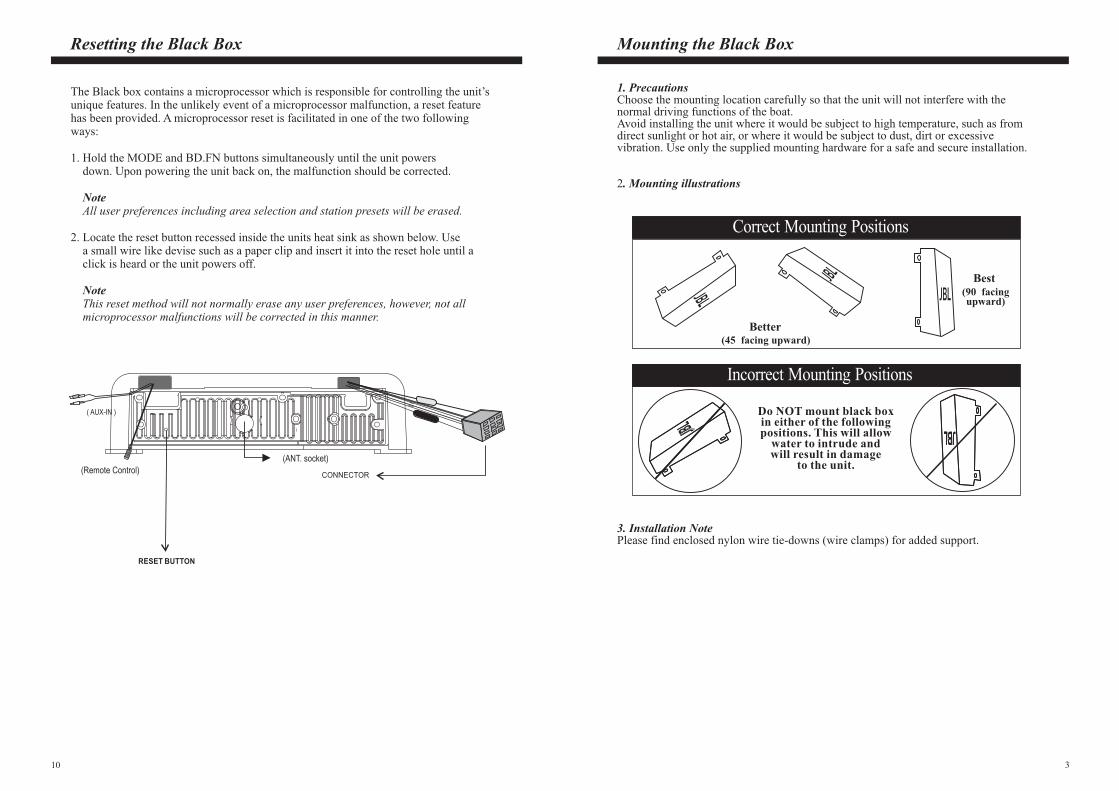
Mounting the Black Box
1. PrecautionsChoose the mounting location carefully so that the unit will not interfere with thenormal driving functions of the boat.Avoid installing the unit where it would be subject to high temperature, such as fromdirect sunlight or hot air, or where it would be subject to dust, dirt or excessivevibration. Use only the supplied mounting hardware for a safe and secure installation.
2. Mounting illustrations
JBL JBL JBL JBL
Do NOT mount black boxin either of the followingpositions. This will allow
water to intrude andwill result in damage
to the unit.
Better(45 facing upward)
Best(90 facingupward)JBL
JBL
JBL
Correct Mounting Positions
Mounting ExamplesIncorrect Mounting Positions
3. Installation NotePlease find enclosed nylon wire tie-downs (wire clamps) for added support.

4 9
Important notes
Connecting the Speakers and Power Cables
Before you wire your system, disconnect your boat battery's positive (+) cable.
This helps prevent damage in case of a short. When you complete the wiring,
reconnect the battery cable and test your marine stereo. When connecting your
marine stereo's black ground wire, be sure to connect the wire to a metal part of
your boat or preferably to the negative (-) terminal of the boat battery.
POSITIVECHASSIS
NEGATIVECHASSIS
Prior to the final installation, perform a sound check. If high distortion or intermittent
sound is experienced, it is possible that the wiring from the receiver to the boat's
electrical system is poor or that the battery needs recharging.
If the battery and its charging circuit are OK, then rewire the yellow fused wire of the receiver directly to the positive terminal (+) of the boat battery.
Marine accessory shops stock the connector blocks and the 10 Amp cable that may
be necessary for extending the fuse wire connection.
Make sure that the black wire on the wiring harness is connected to a good ground
point on the boat. If the chassis of the boat is used as a grounding point, make sure
that the surface is scraped clean of paint before attaching the wire to it.
It is preferable to connect the black ground wire directly to negative terminal (-) of
the boat battery.
This model is only suitable for use in boats which have a Negative ground system,
e. g. : the negative terminal of the boat battery is connected to the chassis.
Grounding
Warning: polarity...
Station Tuning
1 5 7 9 11 13 3
2 6 8 10 12 14 4
1615
1. Radio Operation
2. To Select Band
3. Manual / Seek tuning button (15)
4. Manual Station store
5. A.PS - Auto Store function (13)
6. Scan function (11)
7. Program Memory Scan
Press MOD button (3) to select Radio mode. Station frequency is indicated on display.
Press BD/FN button (4) to toggle through radio modes as follows:FM1 --> FM2 --> FM3 --> AM1 --> AM2 --> FM1.
Press this button quickly to activate the Seek mode. The Seek mode will automaticallyseek up or down the wave band and stop at the next station of sufficient signal strength.Press and hold tuning button for 2 seconds to enter manual tuning mode. The unit willrevert back to Seek mode after 10 seconds without use.
Select the desired band and tune to a radio station to be memorized. Choose the presetbutton memory location span 1-6 into which the station is to be stored and press andhold that preset button for 2 seconds.The station will now be entered into the preset memory. 6 stations can be memorizedon each of the FM1, FM2, FM3, AM1, AM2 bands.
Press and hold A.PS button for approximately 2 seconds until you hear a beep whichconfirms the memory function is engaged. The unit will SEARCH for six strong stationsand automatically store them on buttons 1 - 6. (FM/AM only)You can override the preset station on any button by manually setting a new frequency.
In Radio mode, press the SCAN button to scan strong stations. At the desired station pressthe SCAN button again to stop scanning.
Momentarily press A.PS and the unit will scan for stored stations.Momentarily press it again to stop scanning.

58
Identification of controls and functions
1. Power ON / OFF button
2. SELECT button
3. MODE button < Radio --> AUX-IN >
4. BAND button
5. Radio preset 1 button
6. Radio preset 2 button
7. Radio preset 3 button
8. Radio preset 4 button
9. Radio preset 5 button
10. Radio preset 6 button
11. SCAN button
12. DISP (display) button
13. A.PS - Auto Preset Scan button
14. LOUD (loudness) button
15. TUNE UP/DOWN button
16. VOLUME UP/DOWN button
1 5 7 9 11 13 3
2 6 8 10 12 14 4
1615
3. VOLUME Control (16)
4. MODE Selection (3)
5. CLOCK/TIME Adjustment
6. LOUD Control
Press volume up or down button (16) to increase or decrease volume. Current volume
setting is briefly indicated on the display panel form 00 to 45.
Press MODE button (3) to cycle through available program sources as follows:
Radio --> AUX.
In Radio mode, press DIS button (12) once to display the time.
A. Press and hold the DIS (12) button until time flashes on the display.
B. Press VOL up (16) to set hour.
C. Press VOL down (16) to set minute.
D. Press the DIS (12) button again quickly to accept the adjusted time.
If no button is pressed within 5 seconds, then the unit would automatically accepts
the adjusted time without further intervention from the user.
When listening to music at low volume levels, this feature will boost the bass and treble
response. This action will compensate for the reduction in bass and treble performance
experienced at low volume. To select the loudness feature, press the 0.LD button (14)
once, LOUD icon would appear on the display panel. Press the 0.LD button (14) once
again to turn off loud feature, and LOUD icon would disappear from display panel.
Controls (In Detail) Continued

6
Controls (In Detail) Continued
To adjust the front-rear speaker balance, first select the fader mode by pressing button (2)
until FADER appears on the display panel. Press VOL +/- (16) within 5 seconds to
adjust the front-rear speaker level as desired. The fader position will be shown by the bars
on the display panel from FADER F15 (full front) to FADER R15 (full rear).
d. FADER Control
.
AREA
DSP
2-2. Beep 2nd, I-VOL, Area, DSP Selection
BEEP 2ND --> I-VOL --> AREA --> DSP
a. BEEP Control
b. I-VOL Control
c. AREA Control
d. DSP Control
When the SEL button (2) is held over 2 seconds, the unit will be operated as below:
To adjust the beep mode, first select the beep mode by pressing button (2) until BEEP
appears on the display panel. Press VOL +/- (16) within 5 seconds to select between
BEEP 2ND and BEEP ON. Select BEEP 2ND when you wish to hear BEEP sound
whenever any button is pressed for more than 2 seconds. Select BEEP ON when you
wish to hear BEEP sound whenever any button is pressed.
I-VOL is the volume level the unit will play at when next turned on. To adjust the I-VOL
level, first select the I-VOL mode by pressing button (2) until I-VOL appears on the
display panel. Press VOL +/- (16) within 5 seconds to adjust the I-VOL level from a
minimum of I-VOL 00 to a maximum of I-VOL 45 This feature controls the max
volume level desired when powering the unit on. If the volume level is higher than the
initial volume setting when audio unit is turned off, once the unit is switched back on
again, the unit will keep the volume adjusted to the preset level. If the volume level is
lower than the initial volume setting when unit is turned off, it will remember the lower
level and resume volume at that level when unit is turned on again.
To adjust the area selection, first select the area mode by pressing button (2) until
appears on the display panel. Press VOL +/- (16) within 5 seconds to select between EUR
and USA. Press and hold BD/FN (4) for more than 2 seconds to confirm selection.
To adjust the DSP selection, first select the DSP mode by pressing button (2) until
appears on the display panel. Press VOL +/- (16) within 5 seconds to select an equalizer
curve from 4 music types (FLAT, CLASSIC, POP, ROCK).
DSP OFF : Cancel the sound feature.
FLAT : Normal operation mode.
CLASSIC : For the dramatic depth of classical music in an auditorium.
POP : For the electric excitement of stadium pop.
ROCK : For the subtle extension of the musics dimensions.
7
1. POWER ON/OFF button (1)
2. SELECT button (2)
Push the Power button (1) to turn on the unit. Push the button again to turn off the unit.
2-1 Audio control ( VOLUME / BASS / TREBLE / BALANCE / FADER )
Press SEL button (2) repeatedly to select the desired mode in the following order:
VOL --> BAS --> TRE --> BAL --> FAD.
At each feature, press VOL UP/DOWN button to adjust to the desired level. If the key
or one of the keys is not pressed within 5 seconds, the radio automatically switches into
volume control mode.
Controls (In Detail)
1 5 7 9 11 13 3
2 6 8 10 12 14 4
1615
To adjust the bass tone level, first select the bass mode by pressing button (2) until
BASS appears on the display panel. Press VOL +/- (16) within 5 seconds to adjust
the bass level as desired. The bass level will be shown on the display panel from a
minimum of BASS -7 to a maximum of BASS +7
To adjust the treble tone level, first select the treble mode by pressing button (2) until
TREBLE appears on the display panel. Press VOL +/- (16) within 5 seconds to adjust
the treble level as desired. The treble level will be shown on the display panel from a
minimum of TREBLE -7 to a maximum of TREBLE +7
To adjust the left-right speaker balance, first select the balance mode by pressing button
(2) until BALANCE appears on the display panel. Press VOL +/- (16) within 5 seconds
to adjust the left-rear speaker level as desired. The balance position will be shown by the
bars on the display panel from BALANCE L15 (full left) to BALANCE R15 (full right).
a. BASS Control
b. TREBLE Control
c. BALANCE Control
.
.