operation manual - lambda
TRANSCRIPT
DOSER & HI-DOSER Powder Dosing / Feeding Instrument
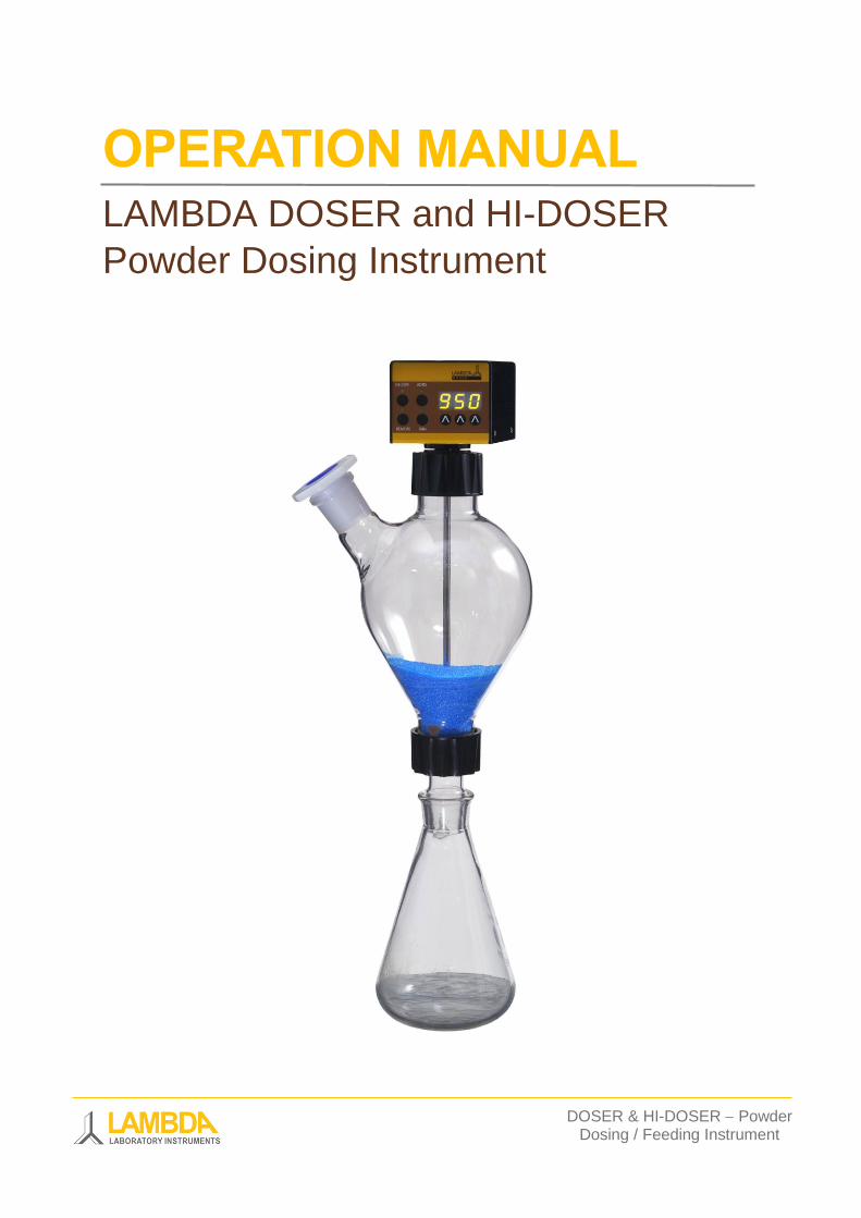
OPERATION MANUAL LAMBDA DOSER and HI-DOSER
Powder Dosing Instrument
DOSER & HI-DOSER Powder Dosing Instrument Operation MANUAL
www.powderdosing.info 1
LAMBDA DOSER & HI-DOSER Powder Dosing Instrument
LAMBDA DOSER and HI-DOSER, unique programmable pump for free-flowing solid
substances.
LAMBDA powder dosing instrument offers safe, controlled and reproducible dosing or
feeding of crystalline or powdery substances at laboratory scale. It allows the automatic or
continuous addition of powders, powdery and crystalline substances without a spoon.
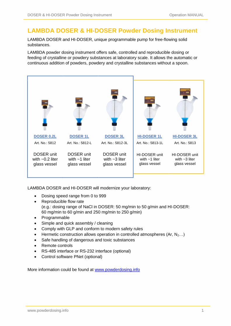
DOSER 0.2L DOSER 1L DOSER 3L HI-DOSER 1L HI-DOSER 3L
Art. No.: 5812 Art. No.: 5812-L Art. No.: 5812-3L Art. No.: 5813-1L Art. No.: 5813
DOSER unit with ~0.2 liter glass vessel
DOSER unit with ~1 liter glass vessel
DOSER unit with ~3 liter glass vessel
HI-DOSER unit with ~1 liter glass vessel
HI-DOSER unit with ~3 liter glass vessel
LAMBDA DOSER and HI-DOSER will modernize your laboratory:
Dosing speed range from 0 to 999
Reproducible flow rate
(e.g.: dosing range of NaCl in DOSER: 50 mg/min to 50 g/min and HI-DOSER:
60 mg/min to 60 g/min and 250 mg/min to 250 g/min)
Programmable
Simple and quick assembly / cleaning
Comply with GLP and conform to modern safety rules
Hermetic construction allows operation in controlled atmospheres (Ar, N2…)
Safe handling of dangerous and toxic substances
Remote controls
RS-485 interface or RS-232 interface (optional)
Control software PNet (optional)
More information could be found at www.powderdosing.info
DOSER & HI-DOSER Powder Dosing Instrument Operation MANUAL
www.powderdosing.info 2
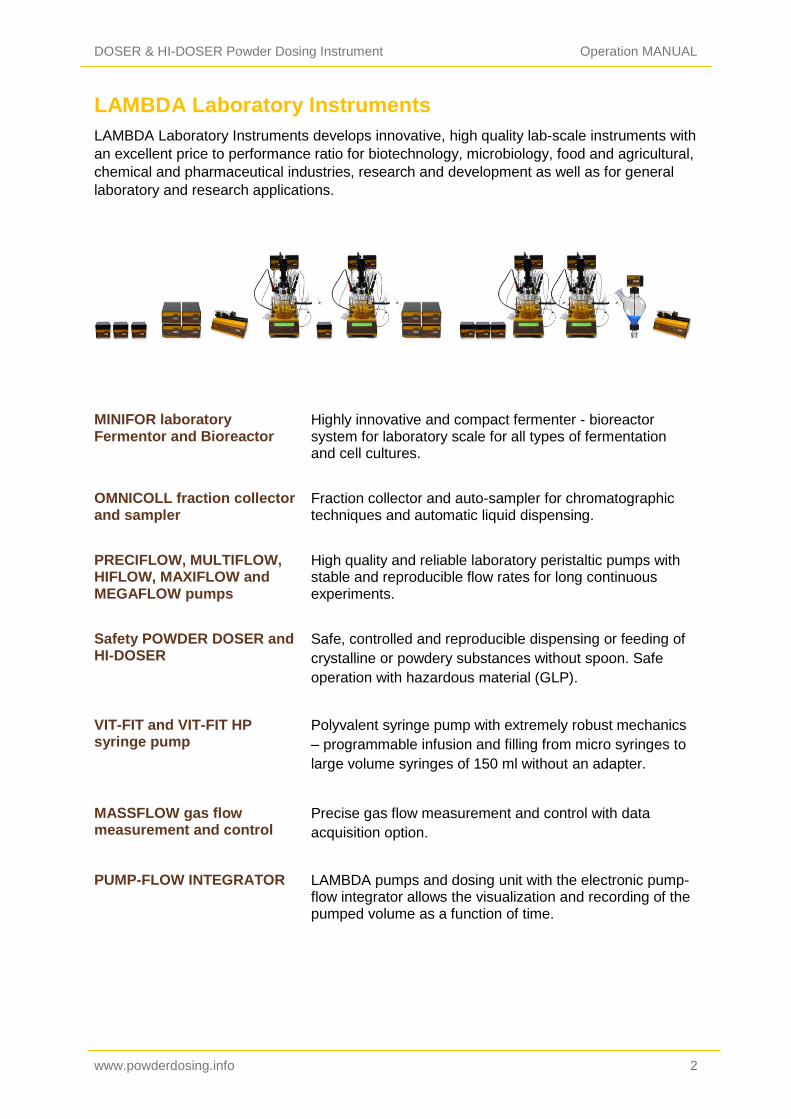
LAMBDA Laboratory Instruments
LAMBDA Laboratory Instruments develops innovative, high quality lab-scale instruments with
an excellent price to performance ratio for biotechnology, microbiology, food and agricultural,
chemical and pharmaceutical industries, research and development as well as for general
laboratory and research applications.
MINIFOR laboratory Fermentor and Bioreactor
Highly innovative and compact fermenter - bioreactor system for laboratory scale for all types of fermentation and cell cultures.
OMNICOLL fraction collector and sampler
Fraction collector and auto-sampler for chromatographic techniques and automatic liquid dispensing.
PRECIFLOW, MULTIFLOW, HIFLOW, MAXIFLOW and MEGAFLOW pumps
High quality and reliable laboratory peristaltic pumps with stable and reproducible flow rates for long continuous experiments.
Safety POWDER DOSER and HI-DOSER
Safe, controlled and reproducible dispensing or feeding of
crystalline or powdery substances without spoon. Safe
operation with hazardous material (GLP).
VIT-FIT and VIT-FIT HP syringe pump
Polyvalent syringe pump with extremely robust mechanics
– programmable infusion and filling from micro syringes to
large volume syringes of 150 ml without an adapter.
MASSFLOW gas flow measurement and control
Precise gas flow measurement and control with data
acquisition option.
PUMP-FLOW INTEGRATOR LAMBDA pumps and dosing unit with the electronic pump-flow integrator allows the visualization and recording of the pumped volume as a function of time.
DOSER & HI-DOSER Powder Dosing Instrument Operation MANUAL
www.powderdosing.info 3
Table of contents
1 Setting up the Powder Doser and HI-DOSER .................................................. 4
1.1 Pre-treatment of the dosing powder ........................................................................ 4 1.2 Assembly of the LAMBDA DOSER and HI-DOSER................................................. 4 1.3 ON/OFF button ........................................................................................................ 7 1.4 Setting of the dosing speed ..................................................................................... 8 1.5 Fast filling function................................................................................................... 8 1.6 Use of the DOSER and HI-DOSER during reflux or under controlled atmosphere ... 9 1.7 FAS / SLO mode of HI-DOSER ............................................................................... 9
2 Programming of the powder DOSER / HI-DOSER ......................................... 10
3 Remote controls ............................................................................................... 14
3.1 ON/OFF remote control ..........................................................................................14 3.2 Remote control of the dosing pump ........................................................................14 3.3 PC control ..............................................................................................................14
4 Cleaning the powder DOSER and HI-DOSER ................................................ 15
5 For your safety ................................................................................................. 15
6 Technical specifications .................................................................................. 16
6.1 General specification ..............................................................................................16 6.2 Remote control (Inputs/outputs) .............................................................................17 6.3 Input (12 V DC) ......................................................................................................18
7 ACCESSORIES AND SPARE PARTS .............................................................. 18
7.1 Pump flow integrator (Art. No. 4803) ......................................................................18 7.2 PNet control software for peristaltic and syringe pumps, HI-DOSER, DOSER or
MASSFLOW (Art. No. 6600) .............................................................................................18 7.3 List of accessories and spare parts ........................................................................19
8 Guarantee ......................................................................................................... 20
9 Appendix ........................................................................................................... 21
9.1 RS communication protocol for DOSER & HI-DOSER, VIT-FIT (HP) syringe pumps,
PRECIFLOW, MULTIFLOW, HIFLOW, MAXIFLOW and MEGALOW peristaltic pumps ...21 9.2 Examples ...............................................................................................................22 9.3 How to set the DOSER or HI-DOSER address? .....................................................22 9.4 RS-connection scheme ..........................................................................................22 9.5 RS communication protocol for the on-board INTEGRATOR (optional) ..................23
DOSER & HI-DOSER Powder Dosing Instrument Operation MANUAL
www.powderdosing.info 4
1 SETTING UP THE POWDER DOSER AND HI-DOSER
1.1 Pre-treatment of the dosing powder
The dosing sample (powders, crystals, solids, etc.) has to be homogenous and free flowing.
If this is not the case, they should be recrystallized, dried and sieved to remove the fines.
The free flow of difficult solids can be achieved by the addition of AEROSIL 200 or 974 at a
concentration of 0.1 to 2 %.
AEROSIL is super finely dispersed pure SiO2. Its particles cover the surface of the crystals
and make it free flowing. AEROSIL is non-toxic, chemically inert and can be removed by
filtration. It can be obtained at a low price from us.
1.2 Assembly of the LAMBDA DOSER and HI-DOSER
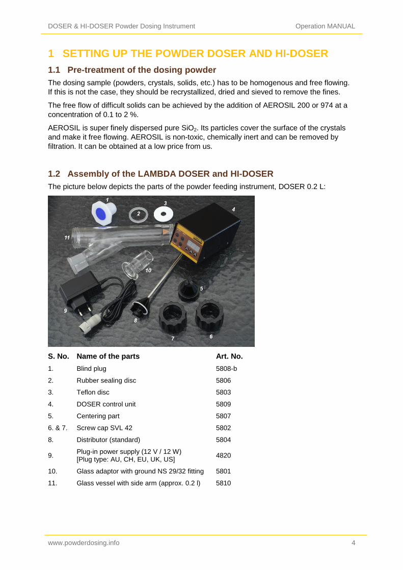
The picture below depicts the parts of the powder feeding instrument, DOSER 0.2 L:
S. No. Name of the parts Art. No.
1. Blind plug 5808-b
2. Rubber sealing disc 5806
3. Teflon disc 5803
4. DOSER control unit 5809
5. Centering part 5807
6. & 7. Screw cap SVL 42 5802
8. Distributor (standard) 5804
9. Plug-in power supply (12 V / 12 W) [Plug type: AU, CH, EU, UK, US]
4820
10. Glass adaptor with ground NS 29/32 fitting 5801
11. Glass vessel with side arm (approx. 0.2 l) 5810
DOSER & HI-DOSER Powder Dosing Instrument Operation MANUAL
www.powderdosing.info 5
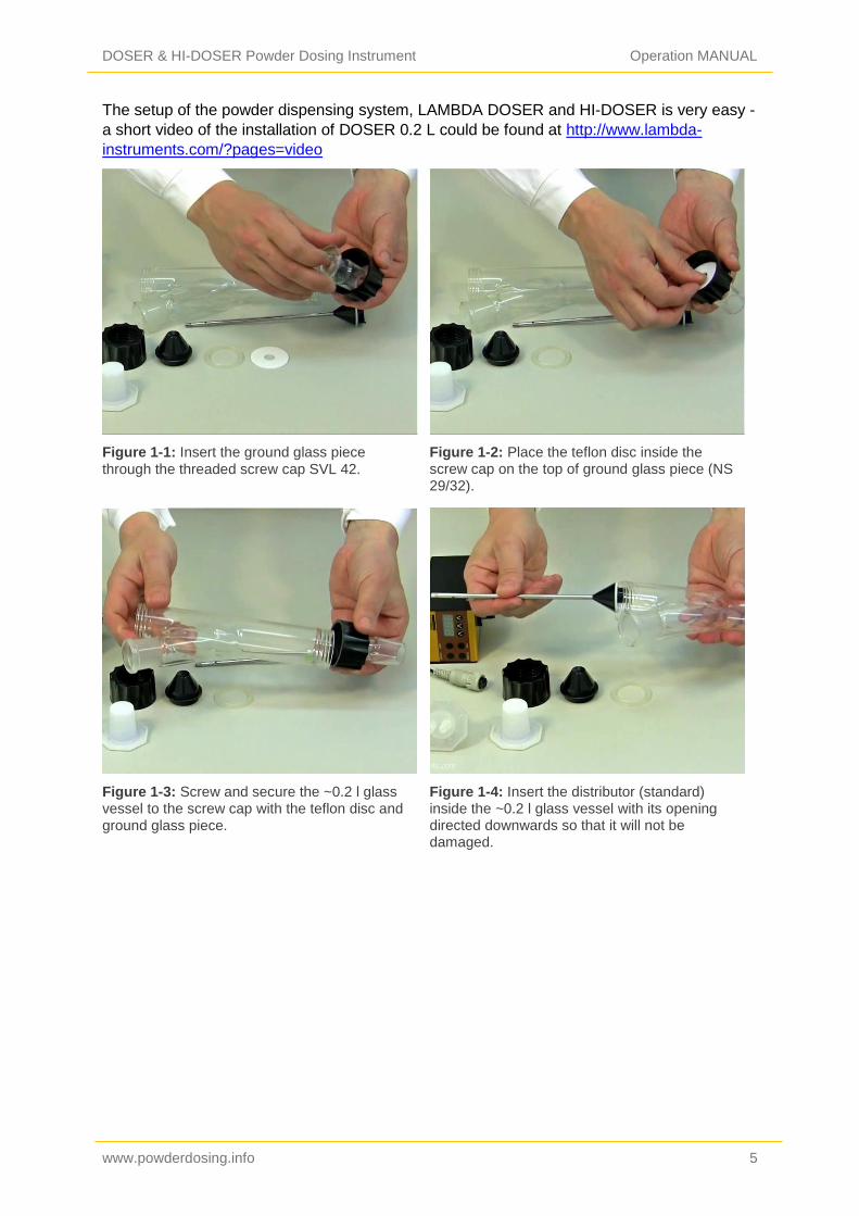
The setup of the powder dispensing system, LAMBDA DOSER and HI-DOSER is very easy -
a short video of the installation of DOSER 0.2 L could be found at http://www.lambda-
instruments.com/?pages=video
Figure 1-1: Insert the ground glass piece
through the threaded screw cap SVL 42.
Figure 1-2: Place the teflon disc inside the screw cap on the top of ground glass piece (NS 29/32).
Figure 1-3: Screw and secure the ~0.2 l glass vessel to the screw cap with the teflon disc and ground glass piece.
Figure 1-4: Insert the distributor (standard) inside the ~0.2 l glass vessel with its opening directed downwards so that it will not be damaged.

DOSER & HI-DOSER Powder Dosing Instrument Operation MANUAL
www.powderdosing.info 6
Figure 1-5: A silicon baffle/scrapper can be found on the lowest part of the glass vessel. The distributor must be turned with its opening towards the baffle/scrapper.
Figure 1-6: Place the teflon treated rubber seal on the centering part with the teflon layer facing outside (towards the glass vessel).
Figure 1-7: Place the centering part with the
rubber seal on the axis of the distributor.
Figure 1-8: Secure the centering part with the rubber seal through the axis of the distributor with the screw cap to the glass vessel.
DOSER & HI-DOSER Powder Dosing Instrument Operation MANUAL
www.powderdosing.info 7
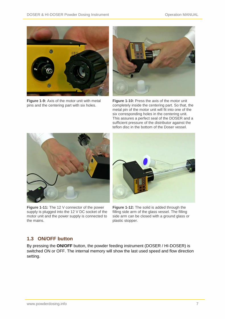
Figure 1-9: Axis of the motor unit with metal
pins and the centering part with six holes.
Figure 1-10: Press the axis of the motor unit completely inside the centering part. So that, the metal pin of the motor unit will fit into one of the six corresponding holes in the centering unit. This assures a perfect seal of the DOSER and a sufficient pressure of the distributor against the teflon disc in the bottom of the Doser vessel.
Figure 1-11: The 12 V connector of the power supply is plugged into the 12 V DC socket of the motor unit and the power supply is connected to the mains.
Figure 1-12: The solid is added through the filling side arm of the glass vessel. The filling side arm can be closed with a ground glass or plastic stopper.
1.3 ON/OFF button
By pressing the ON/OFF button, the powder feeding instrument (DOSER / HI-DOSER) is
switched ON or OFF. The internal memory will show the last used speed and flow direction
setting.

DOSER & HI-DOSER Powder Dosing Instrument Operation MANUAL
www.powderdosing.info 8
1.4 Setting of the dosing speed
The powder dosing rates depend on the powder properties and the DOSER or HI-DOSER
motor rotation speed.
The speed of powder addition is selected by the control buttons Λ Λ Λ under the LED
display. The digital selection allows good reproducibility of the selected dosing rate.
Figure 1-13: Choosing the speed of powder addition with the help of control buttons Λ Λ Λ.
Figure 1-14: Pressing ON/OFF button on the DOSER motor unit after choosing the dosing speed.
Since specific densities of solid substances vary considerably, it is important to calibrate the
DOSER or HI-DOSER before starting the powder dosing.
For this, the amount of substance delivered during a certain time period is measured (e.g. for
1 minute with speed setting 500). The speed of rotation of the distributor increases
progressively with the speed setting value. Using this information, the speed setting
corresponding to the desired flow rate of the solid substance can be calculated easily (rule of
three).
The dosing of the powdery substance is started by pressing the ON/OFF button. The
corresponding LED indicates that powder dosing is in progress.
1.5 Fast filling function
If the ADRS button is pressed continuously for about 2 seconds, the distributor will rotate at
its maximum speed.
After releasing the ADRS button, the powder dispensing is stopped. This function is useful
for fast filling of a recipient or emptying of the glass vessel of the LAMBDA DOSER or HI-
DOSER at the end of powder dosing operation.
The ADRS (“HOLD=MAX”) function can also be used, even if the ON/OFF button has not
been pressed.
DOSER & HI-DOSER Powder Dosing Instrument Operation MANUAL
www.powderdosing.info 9
1.6 Use of the DOSER and HI-DOSER during reflux or under controlled
atmosphere
Vapours of boiling solvents can penetrate into the lower part of the DOSER or HI-DOSER
and condense. The condensation disturbs the flow of the solid, which can be prevented by
purging a light stream of air or other convenient gas through the glass vessel of DOSER or
HI-DOSER. The vapours are displaced and cannot disturb the dosing.
The gas can be introduced into the vessel by a special stopper fitted with tubing. We deliver
a polyethylene stopper for this purpose. However, any fitting, compatible with NS 29/32
ground fittings (e.g. SVL threaded fittings which can be adapted to several tubing diameters
are excellent).
The slight gas stream passes through the hollow axis of the distributor and the lower part of
the DOSER or HI-DOSER vessel. The stream and pressure of the gas must be carefully
controlled to prevent compression of the solid substance during the dosing process.
Since the DOSER and HI-DOSER are airtight, it can also be used to work under controlled
atmosphere (N2, Ar, etc.). The DOSER and HI-DOSER withstands a pressure of ± 0.05 MPa.
The airtight dosing unit is particularly useful while working with oxygen sensitive or
hygroscopic substances. In this case, manual dosing is very difficult.
1.7 FAS / SLO mode of HI-DOSER
The HI-DOSER powder dosing instrument allows to dose the powders at two speed settings:
SLO. = slow and FAS = fast.
In the standard mode (FAS), the flow rate of the speed setting 0 to 999 ranges from approx.
250 mg/min to 250 g/min for NaCl.
In the slow mode (SLO.), the flow rate of the speed setting 0 to 999 ranges from approx. 60
mg/min to 60 g/min for NaCl. The slow mode is indicated by the dot in the last position on the
digital display.
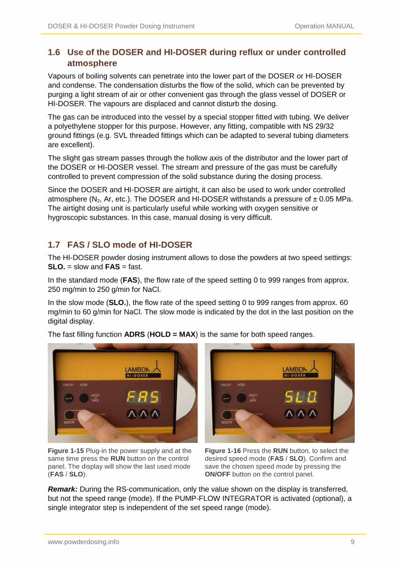
The fast filling function ADRS (HOLD = MAX) is the same for both speed ranges.
Figure 1-15 Plug-in the power supply and at the same time press the RUN button on the control panel. The display will show the last used mode (FAS / SLO).
Figure 1-16 Press the RUN button, to select the desired speed mode (FAS / SLO). Confirm and save the chosen speed mode by pressing the ON/OFF button on the control panel.
Remark: During the RS-communication, only the value shown on the display is transferred,
but not the speed range (mode). If the PUMP-FLOW INTEGRATOR is activated (optional), a
single integrator step is independent of the set speed range (mode).

DOSER & HI-DOSER Powder Dosing Instrument Operation MANUAL
www.powderdosing.info 10
2 PROGRAMMING OF THE POWDER DOSER / HI-DOSER
Up to 27 pairs of speed and time settings (flow rates) can be programmed in DOSER and up
to 99 steps of speed and time can be programmed in HI-DOSER.
The programming mode is accessed by simultaneously pressing the buttons REMOTE and
RUN until the indication “PGM” appears on display and the REMOTE and RUN LEDs are
switched on.
Figure 2-1: Pressing Remote and Run buttons simultaneously and the "PGM" indication appears.
Figure 2-2: Continuous pressing of Remote and Run button even after the indication of "PGM" ends up with the "cLE" indication.
Remark: If you repeat this simultaneous pressing of the REMOTE and RUN buttons, the
memory will be cleared and the indication “cLE” will appear on the display. To enter the
programming mode again, press the REMOTE and RUN buttons again until “PGM” appears.
Figure 2-3: Press the ON/OFF button. The indication “F01” will appear for a short time on the display indicating that you can select the first flow rate (speed setting) value.
Figure 2-4: Set the desired flow rate value for the first program step by pressing the buttons ΛΛΛ below the display (from 0 to 999, corresponding to 0 to 100% of the motor rotation speed).
DOSER & HI-DOSER Powder Dosing Instrument Operation MANUAL
www.powderdosing.info 11
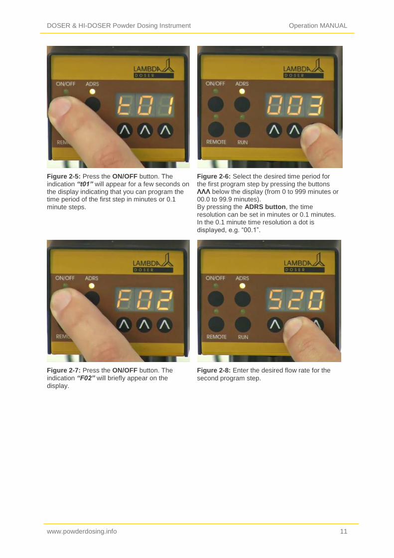
Figure 2-5: Press the ON/OFF button. The indication “t01” will appear for a few seconds on the display indicating that you can program the time period of the first step in minutes or 0.1 minute steps.
Figure 2-6: Select the desired time period for the first program step by pressing the buttons ΛΛΛ below the display (from 0 to 999 minutes or 00.0 to 99.9 minutes). By pressing the ADRS button, the time resolution can be set in minutes or 0.1 minutes. In the 0.1 minute time resolution a dot is displayed, e.g. “00.1”.
Figure 2-7: Press the ON/OFF button. The indication “F02” will briefly appear on the display.
Figure 2-8: Enter the desired flow rate for the
second program step.
DOSER & HI-DOSER Powder Dosing Instrument Operation MANUAL
www.powderdosing.info 12
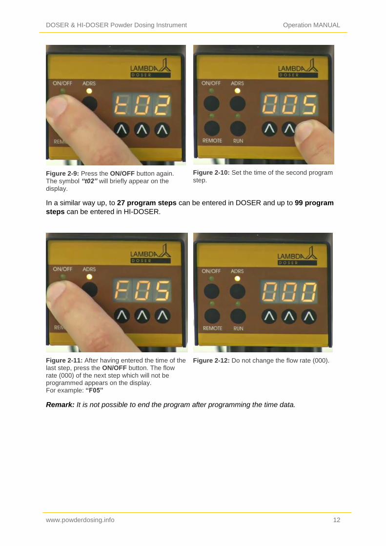
Figure 2-9: Press the ON/OFF button again. The symbol “t02” will briefly appear on the display.
Figure 2-10: Set the time of the second program
step.
In a similar way up, to 27 program steps can be entered in DOSER and up to 99 program
steps can be entered in HI-DOSER.
Figure 2-11: After having entered the time of the last step, press the ON/OFF button. The flow rate (000) of the next step which will not be programmed appears on the display. For example: “F05”
Figure 2-12: Do not change the flow rate (000).
Remark: It is not possible to end the program after programming the time data.
DOSER & HI-DOSER Powder Dosing Instrument Operation MANUAL
www.powderdosing.info 13
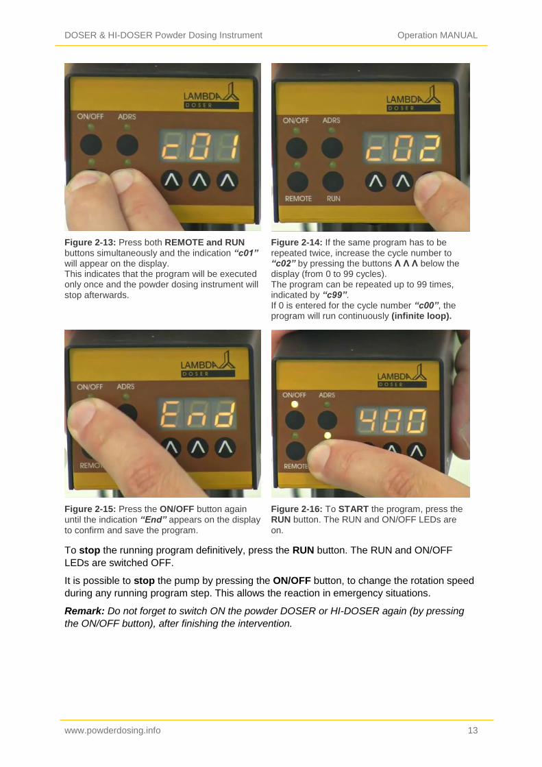
Figure 2-13: Press both REMOTE and RUN buttons simultaneously and the indication “c01” will appear on the display. This indicates that the program will be executed only once and the powder dosing instrument will stop afterwards.
Figure 2-14: If the same program has to be repeated twice, increase the cycle number to “c02” by pressing the buttons Λ Λ Λ below the display (from 0 to 99 cycles). The program can be repeated up to 99 times, indicated by “c99”. If 0 is entered for the cycle number “c00”, the program will run continuously (infinite loop).
Figure 2-15: Press the ON/OFF button again until the indication “End” appears on the display to confirm and save the program.
Figure 2-16: To START the program, press the RUN button. The RUN and ON/OFF LEDs are
on.
To stop the running program definitively, press the RUN button. The RUN and ON/OFF
LEDs are switched OFF.
It is possible to stop the pump by pressing the ON/OFF button, to change the rotation speed
during any running program step. This allows the reaction in emergency situations.
Remark: Do not forget to switch ON the powder DOSER or HI-DOSER again (by pressing
the ON/OFF button), after finishing the intervention.

DOSER & HI-DOSER Powder Dosing Instrument Operation MANUAL
www.powderdosing.info 14
3 REMOTE CONTROLS
3.1 ON/OFF remote control
By interlinking the contacts no. 4 and 5 of the socket at the rear of the pump (see figure 61
and section 6.2), the powder dosing instrument will be blocked and the ON/OFF LED is
switched OFF.
The same effect will be obtained by applying a voltage of 3 to 12 V DC to the contact no. 5 (0
line must be connected to contact no. 3). The remote control cable (Art. no. 4810) is used for
the transmission of the remote control signals.
Remark: In some cases, a reversed logic for the remote control might be desired. In such
cases, please contact us ([email protected]).
3.2 Remote control of the dosing pump
The LAMBDA DOSER and HI-DOSER can be controlled over the whole speed range by an
external signal (0 - 10 V DC, option 0-20 or 4-20 mA). The plus pole of the signal is
connected to the contact no.1, 0 line to the contact no.3.
Press the button REMOTE on the front panel. The corresponding LED diode will go ON and
the display will indicate the approximate voltage of the external signal. This indication may
become unstable when no external connection is made and indicates the high sensitivity of
the electronics.
For safety reasons the voltage of the external signal must not exceed 48 V to earth!
3.3 PC control
If the instrument has been equipped with the optional RS-232 or RS-485 interface, it can be
controlled digitally, e.g. from a PC by PNet control software.
To look up/modify the instrument address; disconnect the DOSER or HI-DOSER from mains.
Press the ADRS button continuously and at the same time connect the DOSER or HI-
DOSER to the mains again.
The message “A” and two numbers will appear on the display. This number from 00 to 99 is
the current address of the powder dosing instrument.
To change the address, press the buttons Λ Λ Λ under the display until the desired number is
obtained.
To confirm and save the address, press the ON/OFF button.

DOSER & HI-DOSER Powder Dosing Instrument Operation MANUAL
www.powderdosing.info 15
4 CLEANING THE POWDER DOSER AND HI-DOSER
After use, the motor unit has to be pulled out of the centering part of DOSER or HI-DOSER
glass vessel, until both separate. Do not be afraid to pull hard, as the blocking mechanism
requires it and at the same time care should be taken to remove it axially and not at any
other angle.
Loosen both threaded caps and separate all components inside the glass vessel. Care
should be taken not to damage the distributor while dismantling the unit (pull it out axially).
The parts can now be washed by common laboratory methods (for example, with ethanol,
acetone, diluted acids or bases). It is however not recommended to expose parts to these
reagents for long periods of time.
The motor and control unit can be cleaned only with a piece of cloth soaked in water
containing a mild detergent, diluted ethanol or with more care iso-propanol. Use of other
solvents could damage the surface of the control unit.
5 FOR YOUR SAFETY
Thanks to the use of a plug-in power supply giving only a low voltage of 12 V DC. The
danger of electrical shock during the use of the DOSER or HI-DOSER powder feeding
system has been virtually eliminated, even when an electro conductive solution penetrates
the DOSER or HI-DOSER.
If the powder dispensing pump is not used for an extended period of time, disconnect it from
the mains.
A modern miniaturized switching power supply is used, which has only a negligible
consumption of electric current when the powder DOSER or HI-DOSER is not in use.
DOSER & HI-DOSER Powder Dosing Instrument Operation MANUAL
www.powderdosing.info 16
6 TECHNICAL SPECIFICATIONS
6.1 General specification
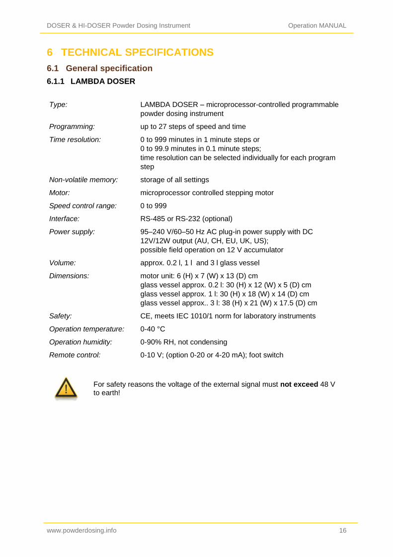
6.1.1 LAMBDA DOSER
Type: LAMBDA DOSER – microprocessor-controlled programmable
powder dosing instrument
Programming: up to 27 steps of speed and time
Time resolution: 0 to 999 minutes in 1 minute steps or
0 to 99.9 minutes in 0.1 minute steps;
time resolution can be selected individually for each program
step
Non-volatile memory: storage of all settings
Motor: microprocessor controlled stepping motor
Speed control range: 0 to 999
Interface: RS-485 or RS-232 (optional)
Power supply: 95–240 V/60–50 Hz AC plug-in power supply with DC
12V/12W output (AU, CH, EU, UK, US);
possible field operation on 12 V accumulator
Volume: approx. 0.2 l, 1 l and 3 l glass vessel
Dimensions: motor unit: 6 (H) x 7 (W) x 13 (D) cm
glass vessel approx. 0.2 l: 30 (H) x 12 (W) x 5 (D) cm
glass vessel approx. 1 l: 30 (H) x 18 (W) x 14 (D) cm
glass vessel approx.. 3 l: 38 (H) x 21 (W) x 17.5 (D) cm
Safety: CE, meets IEC 1010/1 norm for laboratory instruments
Operation temperature: 0-40 °C
Operation humidity: 0-90% RH, not condensing
Remote control: 0-10 V; (option 0-20 or 4-20 mA); foot switch
For safety reasons the voltage of the external signal must not exceed 48 V to earth!
DOSER & HI-DOSER Powder Dosing Instrument Operation MANUAL
www.powderdosing.info 17
6.1.2 LAMBDA HI-DOSER
Type: LAMBDA HI-DOSER – microprocessor-controlled
programmable powder dosing instrument
Programming: up to 99 steps of speed and time
Time resolution: 0 to 999 minutes in 1 minute steps or
0 to 99.9 minutes in 0.1 minute steps;
time resolution can be selected individually for each program
step
Non-volatile memory: storage of all settings
Motor: microprocessor controlled brushless long life BLDC motor
with neodymium magnets
Speed control range: 0 to 999
Interface: RS-485 or RS-232 (optional)
Power supply: 95–240 V/60–50 Hz AC plug-in power supply with DC
12V/50W output (AU, CH, EU, UK, US);
possible field operation on 12 V accumulator
Volume: approx. 1 l and 3 l glass vessel
Dimensions: motor unit: 6 (H) x 7 (W) x 13 (D) cm
glass vessel approx. 1 l: 30 (H) x 18 (W) x 14 (D) cm
glass vessel approx.. 3 l: 38 (H) x 21 (W) x 17.5 (D) cm
Safety: CE, meets IEC 1010/1 norm for laboratory instruments
Operation temperature: 0-40 °C
Operation humidity: 0-90% RH, not condensing
Remote control: 0-10 V; (option 0-20 or 4-20 mA); foot switch
For safety reasons the voltage of the external signal must not exceed 48 V to earth!
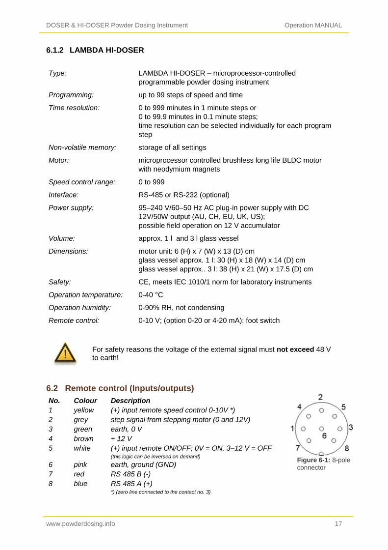
6.2 Remote control (Inputs/outputs)
No. Colour Description
1 yellow (+) input remote speed control 0-10V *)
2 grey step signal from stepping motor (0 and 12V)
3 green earth, 0 V
4 brown + 12 V
5 white (+) input remote ON/OFF; 0V = ON, 3–12 V = OFF (this logic can be inversed on demand)
6 pink earth, ground (GND)
7 red RS 485 B (-)
8 blue RS 485 A (+) *) (zero line connected to the contact no. 3)
Figure 6-1: 8-pole connector

DOSER & HI-DOSER Powder Dosing Instrument Operation MANUAL
www.powderdosing.info 18
Figure 6-2: 3-pole connector
6.3 Input (12 V DC)
Contact No. Description
1 + 12 V DC
2 0 V
3 not connected
7 ACCESSORIES AND SPARE PARTS
7.1 Pump flow integrator (Art. No. 4803)
The DOSER and HI-DOSER powder feeding pump and the other LAMBDA pumps are the
only pumps on the market, which allow a simple and precise integration of the amount of
liquid, solid or gas that has been delivered by the pump.
The electrical impulses, which move the pump motor, are registered and transformed into a
direct voltage. This voltage can be measured or recorded by common recorders or
voltmeters.
In processes where the pump is controlled e.g. by a pH-stat during a fermentation or cell
culture to keep the pH of the medium constant, it is often important to know when and how
much acid or base were added. This data yields important information about the
process, its kinetics and time of completion, etc.
Another use of the INTEGRATOR is for the measurement of enzyme activities (e.g.
amidases, esterases, lactamases, lipases, proteases and other enzymes).
The pump-flow INTEGRATOR can now be electronically implemented inside the DOSER
powder dosing instrument and therefore, does not require any additional valuable laboratory
bench space.
The activated INTEGRATOR within the LAMBDA pumps allows new and unusual pump
applications (e.g. gradient making, counter flow elution, liquid chromatography, electronic
burette, etc.).
7.2 PNet control software for peristaltic and syringe pumps, HI-DOSER,
DOSER or MASSFLOW (Art. No. 6600)
PNet is PC control software for the remote control of LAMBDA laboratory instruments:
peristaltic pumps PRECIFLOW, MULTIFLOW, HIFLOW, MAXIFLOW and MEGAFLOW;
syringe pumps VIT-FIT and VIT-FIT HP; powder dosing instruments DOSER and HI-DOSER;
gas flow controller and measurement unit MASSFLOW.
The pumps are connected to the computer through a RS-232 or RS-485 interface.
Up to 6 instruments of LAMBDA and 12 PUMP-FLOW INTEGRATORs can be connected
and controlled simultaneously.

DOSER & HI-DOSER Powder Dosing Instrument Operation MANUAL
www.powderdosing.info 19
7.3 List of accessories and spare parts
Art. No. Accessories
4803 PUMP-FLOW INTEGRATOR (for LAMBDA pumps, DOSER, HI-
DOSER and MASSFLOW)
4810 Pump remote control (analog and digital) cable, 8 poles (open ends)
4802 Pump ON/OFF remote control cable, 2 poles (open ends)
4823 Foot switch for ON/OFF control, 8 poles
4824 Cable for inverted analog ON/OFF control, 8 poles
Interface and Control software
4822 RS232 interface (for connection of the instruments to the serial port)
4816 RS485 interface (for connection of the instruments to the serial port)
4817 RS232/485 converter
4818 Power supply for RS232/485 converter (5V/1W)
4819 RS-line connection cable (serial)
6600 PNet control software for peristaltic and syringe pumps, DOSER, HI-
DOSER or MASSFLOW
800202 Quadruple plug box (Power and RS-connection for up to 4 LAMBDA
laboratory instruments)
Spare parts
4820 Plug-in power supply (12V/12W) for DOSER, PRECIFLOW,
MULTIFLOW
4821 Plug-in power supply (12V/50W) for HI-DOSER, HIFLOW,
MAXIFLOW, VIT-FIT, MASSFLOW
5801 Glass adaptor with ground NS 29/32 fitting
5802 Screw cap SVL 42
5803 Teflon disc
5804 Distributor (normal)
5805 Distributor for very fluid powders
5806 Rubber/Teflon sealing disc
5807 Centering part
5808-b Blind plug
5808-g Gassing plug
5809 DOSER control unit
5809-L Control unit HI-DOSER
5810 Glass vessel with side arm (approx. 0.2 l)
5811 Glass vessel with side arm (approx. 1 l)
5811-L Glass vessel with side arm (approx. 3 l)
5810-s Silicone coated glass vessel with side arm (approx.. 0.2 l)
5811-s Silicone coated glass vessel with side arm (approx. 1 l)
5811-L-s Silicone coated glass vessel with side arm (approx. 3 l)

DOSER & HI-DOSER Powder Dosing Instrument Operation MANUAL
www.powderdosing.info 20
8 GUARANTEE
LAMBDA provides a two-year guarantee on material and manufacturing defects, if the
instrument was used according to the operation manual.
Conditions of guarantee:
The instrument must be returned with a complete description of the defect or problem.
In order to send back the equipment for repair, you will need a returns authorization
number from LAMBDA.
The customer will send the instrument to our service office.
Damage or loss of items during transport will not be compensated for by LAMBDA.
Failure to fulfil these requirements will disqualify the customer from compensation.
Serial Number: _____________________________
Guarantee from: ____________________________
DOSER & HI-DOSER Powder Dosing Instrument Operation MANUAL
www.powderdosing.info 21
9 APPENDIX
9.1 RS communication protocol for DOSER & HI-DOSER, VIT-FIT (HP)
syringe pumps, PRECIFLOW, MULTIFLOW, HIFLOW, MAXIFLOW
and MEGALOW peristaltic pumps
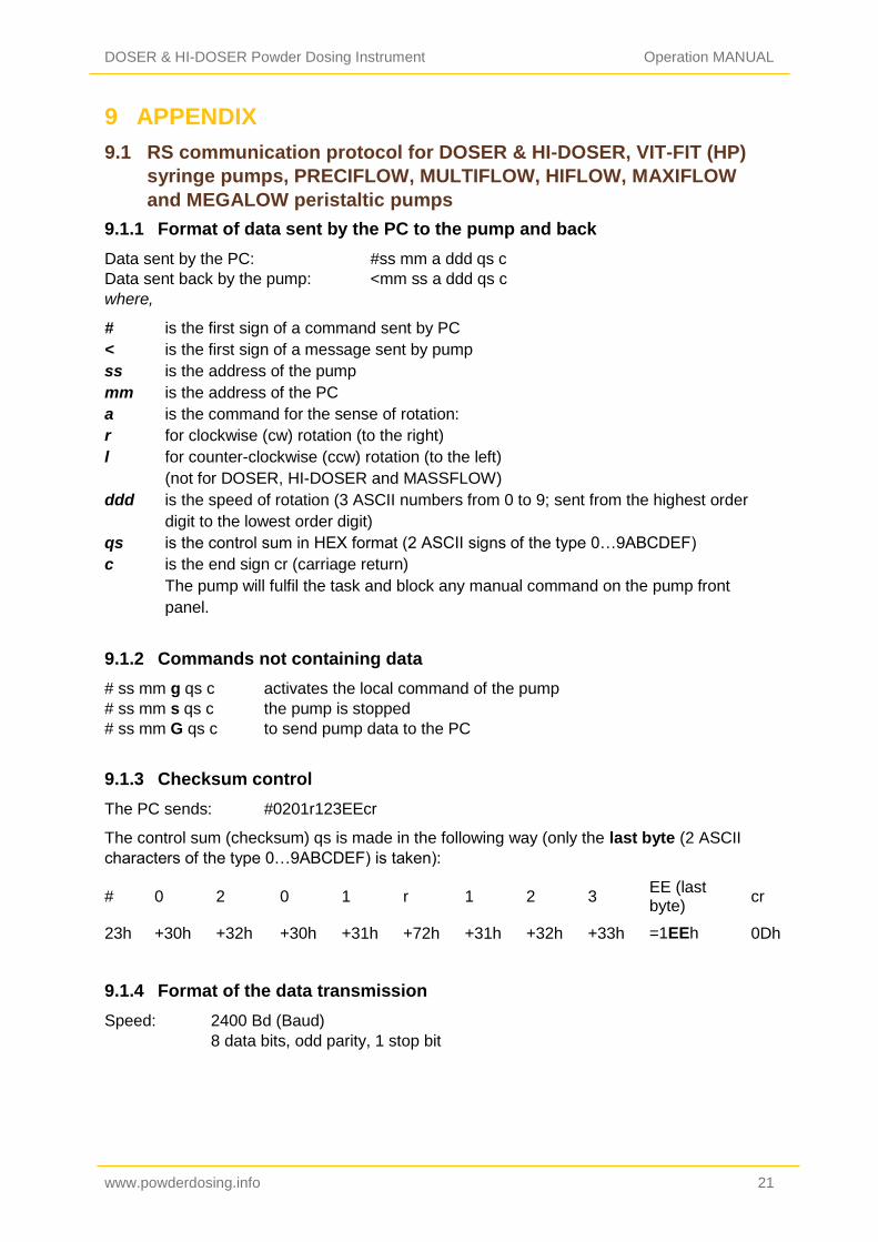
9.1.1 Format of data sent by the PC to the pump and back
Data sent by the PC: #ss mm a ddd qs c
Data sent back by the pump: <mm ss a ddd qs c
where,
# is the first sign of a command sent by PC
< is the first sign of a message sent by pump
ss is the address of the pump
mm is the address of the PC
a is the command for the sense of rotation:
r for clockwise (cw) rotation (to the right)
l for counter-clockwise (ccw) rotation (to the left)
(not for DOSER, HI-DOSER and MASSFLOW)
ddd is the speed of rotation (3 ASCII numbers from 0 to 9; sent from the highest order
digit to the lowest order digit)
qs is the control sum in HEX format (2 ASCII signs of the type 0…9ABCDEF)
c is the end sign cr (carriage return)
The pump will fulfil the task and block any manual command on the pump front
panel.
9.1.2 Commands not containing data
# ss mm g qs c activates the local command of the pump
# ss mm s qs c the pump is stopped
# ss mm G qs c to send pump data to the PC
9.1.3 Checksum control
The PC sends: #0201r123EEcr
The control sum (checksum) qs is made in the following way (only the last byte (2 ASCII
characters of the type 0…9ABCDEF) is taken):
# 0 2 0 1 r 1 2 3 EE (last byte)
cr
23h +30h +32h +30h +31h +72h +31h +32h +33h =1EEh 0Dh
9.1.4 Format of the data transmission
Speed: 2400 Bd (Baud)
8 data bits, odd parity, 1 stop bit
DOSER & HI-DOSER Powder Dosing Instrument Operation MANUAL
www.powderdosing.info 22
Figure 9-1: 8 pole connector
9.2 Examples
Address of the PC: 01
Address of the pump: 02
The PC sends: #0201r123EEcr
The pump will rotate cw at the speed of 123
The PC sends: #0201G2Dcr
The answer of the pump: <0102r12307cr
The PC sends: #0201l123E8cr
The pump will rotate ccw at the speed of 123. (not for DOSER, HI-DOSER and MASSFLOW)
The PC sends: #0201s59cr
The pump stops.
The PC sends: #0201g4Dcr
The pump will go to the local command (pump front panel is activated).
9.3 How to set the DOSER or HI-DOSER address?
To look up/modify the instrument address; disconnect the DOSER or HI-DOSER from mains.
Press the ADRS button continuously and at the same time connect the DOSER or HI-
DOSER to the mains again.
The message “A” and two numbers will appear on the display. This number from 00 to 99 is
the current address of the powder dosing instrument.
To change the address press the buttons Λ Λ Λ under the display until the desired number is
obtained.
To confirm and save the address, press the ON/OFF button.
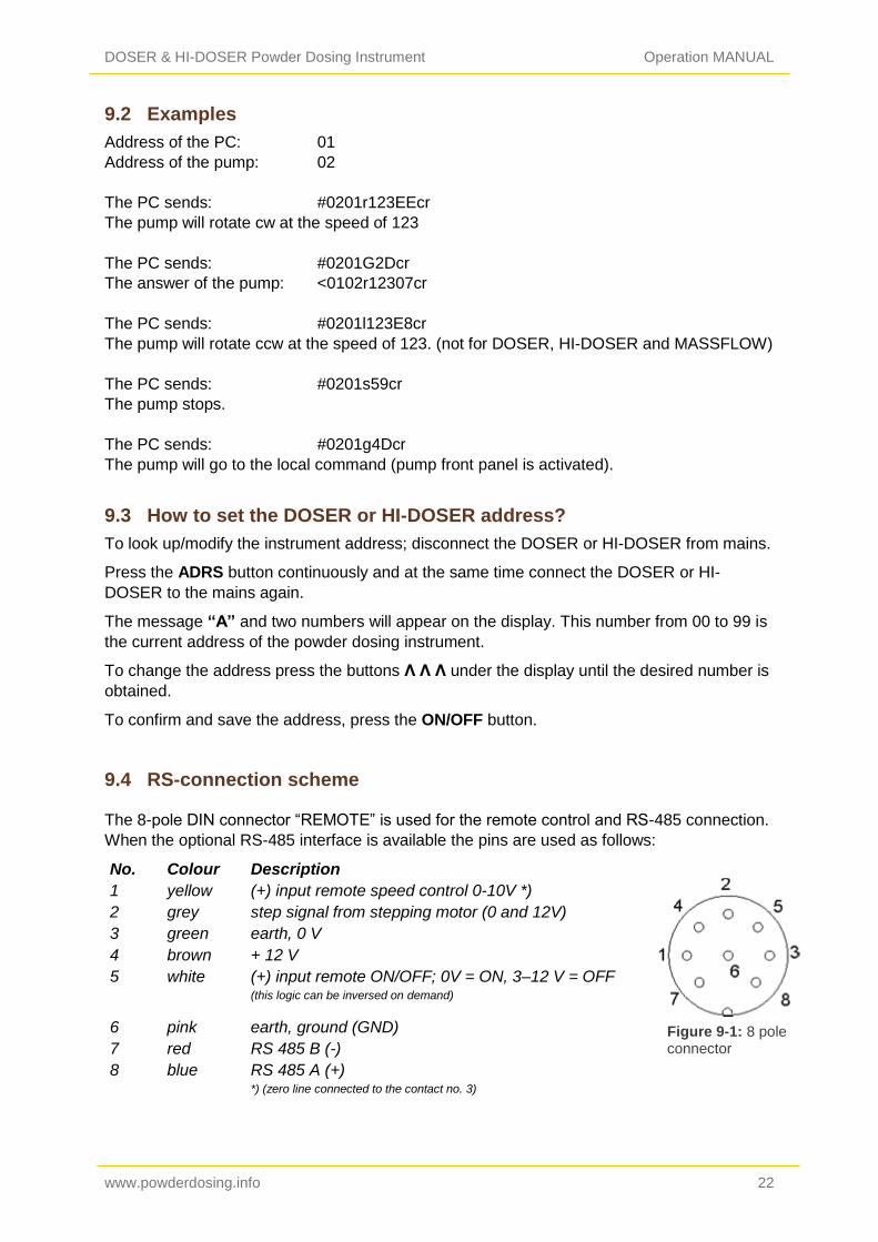
9.4 RS-connection scheme
The 8-pole DIN connector “REMOTE” is used for the remote control and RS-485 connection.
When the optional RS-485 interface is available the pins are used as follows:
No. Colour Description
1 yellow (+) input remote speed control 0-10V *)
2 grey step signal from stepping motor (0 and 12V)
3 green earth, 0 V
4 brown + 12 V
5 white (+) input remote ON/OFF; 0V = ON, 3–12 V = OFF (this logic can be inversed on demand)
6 pink earth, ground (GND)
7 red RS 485 B (-)
8 blue RS 485 A (+) *) (zero line connected to the contact no. 3)

DOSER & HI-DOSER Powder Dosing Instrument Operation MANUAL
www.powderdosing.info 23
9.5 RS communication protocol for the on-board INTEGRATOR
(optional)
9.5.1 Communication between the PC and INTEGRATOR of the LAMBDA
instrument
From the PC to the INTEGRATOR:
#ss mm z qs c
From the INTEGRATOR to the PC:
<mm ss = qs c confirmation of the reception of a command
<mm ss dddd qs c sending of the requested data
where,
# is the first sign of a command sent by the MASTER (PC)
< is the first sign of a message sent by the SLAVE (INTEGRATOR)
ss is the address of the subordinate station (address of the instrument with integrated
INTEGRATOR)
mm is the address of the commanding station (PC)
z is a command (see below): small letters indicate a command, capital letters request
data transfer from the subordinate station
= confirmation of reception
aa new address of the subordinate station (ss) (two numbers and possibly other ASCII
characters A B C D E F)
dddd transferred data (values are two bytes in hexadecimal form. Single bytes are
transformed into two ASCII characters 0,..,9,A,B,C,D,E,F)
qs is the control sum (obtained by the addition modulo 256 of binary values of all
preceding characters including the leading sign) in HEX format (2 ASCII signs of the
type 0…9ABCDEF)
c is the end sign cr (carriage return)
9.5.2 Commands for the INTEGRATOR
n reset (sets the INTEGRATOR to zero)
i start of integration
e stop of integration
I sends the integrated value
N sends the integrated value and sets the integrator to zero
L sends the integrated value ccw rotation (to the left) (not for DOSER
and HI-DOSER)
R sends the integrated value of cw rotation (to the right)
DOSER & HI-DOSER Powder Dosing Instrument Operation MANUAL
www.powderdosing.info 24
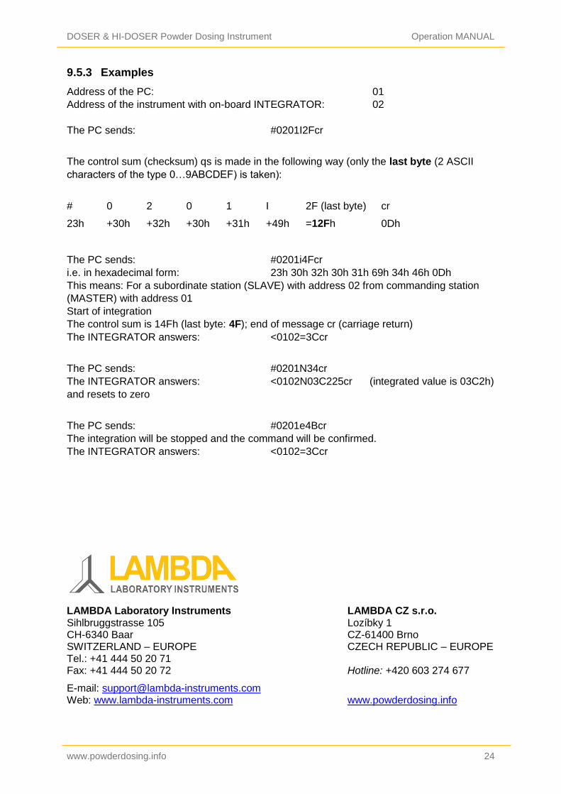
9.5.3 Examples
Address of the PC: 01
Address of the instrument with on-board INTEGRATOR: 02
The PC sends: #0201I2Fcr
The control sum (checksum) qs is made in the following way (only the last byte (2 ASCII
characters of the type 0…9ABCDEF) is taken):
# 0 2 0 1 I 2F (last byte) cr
23h +30h +32h +30h +31h +49h =12Fh 0Dh
The PC sends: #0201i4Fcr
i.e. in hexadecimal form: 23h 30h 32h 30h 31h 69h 34h 46h 0Dh
This means: For a subordinate station (SLAVE) with address 02 from commanding station
(MASTER) with address 01
Start of integration
The control sum is 14Fh (last byte: 4F); end of message cr (carriage return)
The INTEGRATOR answers: <0102=3Ccr
The PC sends: #0201N34cr
The INTEGRATOR answers: <0102N03C225cr (integrated value is 03C2h)
and resets to zero
The PC sends: #0201e4Bcr
The integration will be stopped and the command will be confirmed.
The INTEGRATOR answers: <0102=3Ccr
LAMBDA Laboratory Instruments Sihlbruggstrasse 105 CH-6340 Baar SWITZERLAND – EUROPE Tel.: +41 444 50 20 71 Fax: +41 444 50 20 72
LAMBDA CZ s.r.o. Lozíbky 1 CZ-61400 Brno CZECH REPUBLIC – EUROPE Hotline: +420 603 274 677
E-mail: [email protected] Web: www.lambda-instruments.com
www.powderdosing.info