operation manual (communication edition)
TRANSCRIPT

- 1 -
TOHO ELECTRONICS INC.
Operation Manual (Communication Edition)
(TOHO Protocol, MODBUS)
Model: TTM-000W Series
Name: Digital Controller

- 2 -
Thank you very much for purchasing the TTM-000W Series (with a communication function).
Kindly read this operation manual for proper usage.
Table of Contents
1. Before Using the Product . . . . . Page 4
1.1 About the Operation Manual
1.2 Requirements for Communication
1.3 Things the Communication Function Can Do
1.4 Position (Priority) of Communication
1.5 Settings to Be Made Prior to the Communication
2. Setting about TOHO Communication. .. Page 5
2.1 Outline
2.2 Setting of Data Length
2.3 Setting of Stop Bit
2.4 Setting of Parity
2.5 Setting of BCC Checking
2.6 Setting of Communication Speed
2.7 Setting of Communication Address
2.8 Setting of Response Delay Time
2.9 Switching of Communication Mode
3. TOHO Communication Control. . . .. Page 8
3.1 Communication Procedures
3.2 Kinds of Message
3.3 Structure of Request Message (Data transmission from upper computer to this product)
3.4 Structure of Response Message (Data transmission from this product to upper computer)
3.5 Explanation about Codes (e.g., List of Errors)
3.6 Things to Be Noted during the Communication
4. Sample TOHO Communication. . . . .Page 14
4.1 Sample Communication for Reading
4.2 Sample Communication for Writing
5. Setting about MODBUS Communication. .Page 16
5.1 Outline
5.2 Setting of Data Length
5.3 Setting of Stop Bit
5.4 Setting of Parity
5.5 Setting of BCC Checking
5.6 Setting of Communication Speed
5.7 Setting of Communication Address
5.8 Setting of Response Delay Time
5.9 Switching of Communication Mode

- 3 -
6. MODBUS Communication Control. . . Page 19
6.1 Communication Procedures 6.2 Kinds of Message 6.3 Structure of RTU Request Message (Data transmission from upper computer to this product) 6.4 Structure of RTU Response Message (Data transmission from this product to upper computer) 6.5 Explanation about RTU Codes (e.g., List of Errors) 6.6 Things to Be Noted during RTU Communication 6.7 Sample Computation of CRC-16 6.8 Structure of ASCII Request Message (Data transmission from upper computer to this
product) 6.9 Structure of ASCII Response Message (Data transmission from this product to upper
computer) 6.10 Explanation about ASCII Codes (e.g., List of Errors) 6.11 Things to Be Noted during ASCII Communication 6.12 Sample Computation of LRC 7. Specifications . . . . . . . Page 32 7.1 Type of Communication Standard 7.2 Communication Specifications 8. Wiring . . . . . . . . . . Page 33 9. List of Identifiers (Codes) . . . Page 34 10. List of ASCII Codes . . . . . . Page 38
- 4 -
1. Before Using the Product 1.1 About the Operation Manual This manual explains the communication function of TTM-000W (hereinafter referred to as "Product"). 1.2 Requirements for Communication The communication function of the product is optional. Therefore, you need to specify the communication
option (RS-485) upon purchase. 1.3 Things the Communication Function Can Do This function allows the user to write and read the items of this product that are described in "9.
List of Identifiers,"
such as "To change, start, or stop items that can be operated through front keys" and "To read the
information that can be displayed on the display section." However, since the RAM of this product is used during the reading/writing of data through
ordinary command, data that was written will be replaced by the previous data (data that is saved
in the EEPROM) if the power is turned OFF and then turned ON.
To save the written data into the EEPROM of this product, execute the save request message.
(See 3.6, 6.6, and 6.11, “Things to Be Noted during the Communication.”) Furthermore, unnecessary setting items, such as items that are related to the unattached option, will
not be read and written. 1.4 Position (Priority) of Communication This product allows the user to change data and parameters through the key even during the operation
under communication mode. Change of settings of data and parameters via communication will be disabled while the product is operated
under RO (Read Only) (provided, however, that the switching of communication mode is possible). 1.5 Settings to Be Made Prior to the Communication Several settings need to be made to this product in order for it to perform a communication function.
See "2. Setting about TOHO Communication" or "5. Setting about MODBUS Communication."

- 5 -
2. Setting about TOHO Communication 2.1 Outline Initial settings need to be made to the product in order for it to perform a communication function.
The setting shall be done by keys at the front side. Follow the procedure shown below to navigate between setting screens. See the User's Manual of this
product for details.
Power ON
↓
Initial Screen (4 seconds)
↓
Operation Mode
↓MODE Key More than 2 seconds
Setting Mode Selection Screen
↓ ▲▼ Key
Communication Setting Mode
↓MODE Key
Setting of Communication Protocol : TOHO Communication Protocol (Initial (alue: )
↓MODE Key
Setting of Communication Parameters
↓MODE Key
Setting of Communication Speed
↓MODE Key
Communication Address Setting
↓MODE Key
Setting of Response Delay Time
↓MODE Key
Setting of the Switching of Communication Mode
↓MODE Key Back to Communication Setting Mode
When the setting is done, press the MODE key for more than 2 seconds to return to the operation
mode. Each parameter shown above is the initial value.

- 6 -
2.2 Setting of Data Length 2.3 Setting of Stop Bit 2.4 Setting of Parity 2.5 Setting of BCC Checking Set the value by pressing the ▲▼ keys on the "Setting of Communication Parameters" screen in a previous
page. The initial value is .
****
Stop Bit 1 Stop Bit 2
Without Parity Odd Parity Even Parity
Data Length 7 Bits Data Length 8 Bits
Without BCC Checking With BCC Checking
2.6 Setting of Communication Speed Set the value by pressing the ▲▼ keys on the "Setting of Communication Speed" screen in a previous
page. The initial value is .
****
1200 BPS 2400 BPS 4800 BPS 9600 BPS 19200 BPS
2.7 Setting of Communication Address Set the value by pressing the ▲▼ keys on the "Setting of Communication Address" screen in a previous
page. The initial value is .
Setting Range: 1-99 stations (Setting of 0 is not allowed)
2.8 Setting of Response Delay Time Set the time to take for the upper computer to complete the receiving of "request message," open the
line, and get ready for the next input. Set the value by pressing the ▲▼ keys on the "Setting of Response Delay Time" screen in a previous
page. The initial value is .
Setting Range: 0-250mSEC
*Communication may not be performed properly if the response delay time is too short. *In actual operation, the processing time of the product will be added to the response delay time.

- 7 -
2.9 Switching of Communication Mode Set the value by pressing the ▲▼ keys on the "Setting of the Switching of Communication Mode" screen
in a previous page. The initial value is .
Read/Write
Read Only 3. TOHO Communication Control 3.1 Communication Procedures This product returns the "response message" as a reply to the "request message" that will be sent
by the upper computer. Therefore, the transmission will never be initiated by this product.
3.2 Kinds of Message
■ Kinds of message can be briefly classified into the following:
■ All codes up to ETX, such as STX and data (except for BCC), will be expressed in ASCII code. ■ To code the program for the upper computer, see "9. List of Identifiers" and "10. List of ASCII
Codes" at the end of this document.

- 8 -
3.3 Structure of Request Message (Data transmission from upper computer to this product) ■ See "3.5 Explanation about Codes" for codes from ① to ⑩. ■ See "4.1 Sample Communication for Reading" and "4.2 Sample Communication for Writing" for concrete
samples of the request message. 3.3.1 Structure of Read Request Message
3.3.2 Structure of Write Request Message
3.3.3 Structure of Save Request Message

- 9 -
3.4 Structure of Response Message (Data transmission from this product to upper computer) ■ See "3.5 Explanation about Codes" for codes from ① to ⑩. ■ See "4.1 Sample Communication for Reading" and "4.2 Sample Communication for Writing" for concrete
samples of the request message. 3.4.1 Response Message for Read Request Message
3.4.2 Response Message for Write/Save Request Message
3.4.3 Response Message for the Error

- 10 -
3.5 Explanation about Codes ■ The following codes from ① STX, ② Address, up to ⑩ Error Type will be expressed in ASCII code: ■ See "10. List of ASCII Codes" for the details about ASCII codes. ■ To convert into ASCII code, see "4. Sample TOHO Communications."
① STX It is a code that is necessary for the receiving side to detect the start of the message.
It shall be attached to the start of the character string to be sent.
② Address It is an address of the device that will be communicated by the upper computer (this product).
The address in the response message from this product indicates the source of the response
message.
③ Contents of Request Set the symbol R, W, L, or B. R: If the data is to be read from the product W: If the data is to be written or saved into the product L: If the blind setting is to be read from the product B: If the blind setting is to be written into the product
④ Identifier It is a classification symbol (identifier) of the data to be read or written that will be
expressed by the 3-digit alphanumeric characters. See "9. List of Identifiers (Codes)."
⑤ Numerical Data It is a data for reading or writing which will be expressed in 5-digit characters regardless
of the data type. Negative data: The symbol "-" is considered one digit to be displayed at the largest digit. Position of decimal point: Decimal point will not be included in the 5-digit data. Example: 5-digit numerical data "-1999" means the following:
Settings Meaning of Numerical
Value
Data of which the posi-tion of decimal point can be changed (PV/SV), etc.
If the position of decimal point [_ dP] is 0
-1999
If the position of decimal point [_ dP] is 0.0
-199. 9
If the position of decimal point [_ dP] is 0.00
-19. 99
If the position of decimal point [_ dP] is 0.000
-1. 999

- 11 -
⑥ ETX It is a code that is necessary for the receiving side to detect the end of the message.
It shall be attached to the end of the character string to be sent (except for BCC).
⑦ BCC Get the Ex-OR of all characters from STX to ETX with the check code for the detection of error. This code shall not be included in the response message if BCC Check is turned OFF at the
communication setting of this product. See "2. Setting about TOHO Communication." ⑧ ACK It is an acknowledge code that will be included in the "response message" to be replied by
this product if no error is found in the received message. ⑨ NAK It is a reject code that will be included in the "response message" to be replied by this
product if error is found in the received message. If there is an error in the received "request message," content of error (⑪ Type of ERR)
will also be attached (next to NAK) to the "response message" that will be returned by this
product. ⑩ Type of ERR If there is an error in the "request message" that was received by this product, the
description of the said error (number in the table shown below) will be attached (next to
"⑨ NAK") to the "response message" that will be returned by this product. Since error number "0" indicates the breakdown of measuring equipment (memory error or A/D
conversion error), it will be included in the "response message" whether or not there is an
error in the "request message." Since error number "9" indicates AT error, it will be included in the "response message" whether
or not there is an error in the "request message." Remove the cause of the error immediately
and restart the AT. For multiple errors, the largest error number will be included. Contents and classification of error are the following:
Error Number Description of errors in the "request message" that was received by this product
0 Malfunction of measuring equipment (memory error or A/D conversion error)
1 Numerical value data is out of the "setting range that is specified individually by the
setting item"
2 Changing of the requested item is prohibited or no item to read
3 ASCII code that is other than the numeric value has been set to the portion for the
numeric value.
ASCII code that is other than "0" or "-" has been set to the position for the symbol.
4 Format Error
5 BCC Error
6 Overrun Error
7 Framing Error
8 Parity Error
9 P( abnormality has occurred during AT or AT does not end although 3 hours have lapsed

- 12 -
3.6 Things to Be Noted during the Communication
3.6.1 Timing of Transmission Upon using RS-485, set enough response delay time to ensure the communication (sending/receiving)
with the host computer. See Figure of "3.1 Communication Procedures" and "2.8 Setting of Response Delay Time." 3.6.2 Request Interval If the "request message" is to be sent continuously by the upper computer, wait for at least
2msecs. from the arrival of the "response message" from this product before sending the next
request message. 3.6.3 Conditions for Response This product will not return the "response message" if STX and ETX (BCC) are not included in
the "request message." Therefore, although there is an error in the "request message," the "response message" with NAK
And ERR will not be returned unless the above condition is met. Therefore, the upper computer should resend the necessary "request message" if the "response
message" is not returned within the reasonable time. Once STX is received, this product clears all codes that were received prior to the said STX. 3.6.4 Address Specification Error This product will not respond to any "request message" that specifies the address that is other
than the one that has been set to itself. Therefore, if there is an error in the address section of the "request message," none of the slave
stations will return the "response message." Therefore, the upper computer should resend the necessary "request message" if the "response
message" is not returned within the reasonable time. Once STX is received, this product clears all codes that were received prior to the said STX. 3.6.5 Number of Digits of Data and Position of Decimal Point See "3.5 Explanation about Codes ⑤ Numerical Data." 3.6.6 Operation After the Receiving of Save Request Message This product starts the saving of data once it receives the save request message correctly from
the upper computer. Only the data that is different from the one stored in the EEPROM (changed data) shall be saved.
Time that is required to save the data (TW) is within 6 seconds. The product sends a response (ACK) when the saving of data is completed. Some data may be lost if the product is turned OFF while the saving process is in progress. Do not
turn the power of this product OFF for at least 6 seconds after the sending of the save request message. 3.6.7 Upon Turning the Power ON This product will not perform any communication for approximately 4 seconds after turning its power
ON (no response). Set the delay from power ON to start communication. 3.6.8 Saving the Data Other than Save Request Message This product saves the parameter into the EEPROM even without receiving the save request message
In case of the following:
1) If the parameter is changed through key operation, it writes only changed parameters and
other related parameters.
2) If the auto tuning is activated and ended normally, only the PID constant will be written. 3.6.9 Change of Setting (alue (S( or S(2) by the Communication during Auto Tuning
If the value for control (S( or S(2) is changed via communication while the auto tuning is performed,
the said value (S( or S(2) will not be changed until auto tuning ends.

- 13 -
4. Example of TOHO Communication 4.1 Sample Communication for Reading Example:
Request Message: Request this product, which address is set as "27," to read the measured value
(P(). (Upper computer) For the above request, Response Message: Returns the data (00777) of the measured value (P(). (This product)
Read Request Message (to be sent by the upper computer)
STX27R
BCC
PV1ETX
①②③|④|⑥⑦
STX27
ACK
BCC
PV1ETX
①②⑧|④| ⑥⑦
00777
||⑤||
Code Symbol・Data ASCII Code Note 2)
① Start Code STX 02H
② Address 27 32H 37H
③ Contents of Request R (Read) 52H
④ Identifier Note 1 P(1 50H 56H 31H
⑤ Numerical Data 00777 30H 30H 37H 37H 37H
⑥ End Code ETX 03H
⑦ BCC Data Request Re-sponse
61H
02H
⑧ Acknowledgment Code ACK 06H
Note 1: See "9. List of Identifiers (Codes)." Note 2: See "10. List of ASCII Codes" for the details about ASCII codes.

- 14 -
4.2 Sample Communication for Writing Example:
Request Message: Request this product, which address is set as "03," to "set 011" (write 011)
to E1F (upper computer). (Set the function of Event 1 to Minimum Deviation + Retain) For the above request, Response Message: Return the message to tell that the request message has been received. (This product) ☆ Read the data separately to check if the data is written correctly. Write Request Message (to be sent by the upper computer)
STX03
ACK
BCC
ETX
①②⑥⑦⑧
STX03W
BCC
E1FETX
①②③|④| ⑥⑦
00011
||⑤||
Code Symbol・Data ASCII Code Note 2)
① Start Code STX 02H
② Address 03 30H 33H
③ Contents of Request W (Write) 57H
④ Identifier Note 1 EIF 45H 31H 46H
⑤ Numerical Data 00011 30H 30H 30H 31H 31H
⑥ End Code ETX 03H
⑦ BCC Data Request Re-sponse
57H
04H
⑧ Acknowledgment Code ACK 06H
Note 1: See "9. List of Identifiers (Codes)." Note 2: See "10. List of ASCII Codes" for the details about ASCII codes.

- 15 -
5. Setting about MODBUS Communication 5.1 Outline Initial settings need to be made to the product in order for it to perform a communication function.
The setting shall be done by keys at the front side. Follow the procedure shown below to navigate between setting screens. See the User's Manual of the
product for details. If MODBUS (RTU) If MODBUS (ASCII)
Power ON Power ON
↓ ↓
Initial Screen (4 seconds)
Initial Screen (4 seconds)
↓ ↓
Operation Mode
Operation Mode
↓MODE Key More than 2 seconds ↓MODE Key More than 2 seconds
Setting Mode Selection Screen
Setting Mode Selection Screen
↓ ▲▼ Key ↓ ▲▼ Key
Communication Setting Mode
Communication Setting Mode
↓MODE Key ↓MODE Key
Setting of Communication Protocol :MODBUS(RTU) (Initial (alue: )
Setting of Communication Protocol : MODBUS(ASCII) (Initial
↓MODE Key ↓MODE Key
Setting of Communication Parameters
Setting of Communication Param-eters
↓MODE Key ↓MODE Key
Setting of Communication Speed
Setting of Communication Speed
↓MODE Key ↓MODE Key
Communication Address Setting
Communication Address Setting
↓MODE Key ↓MODE Key
Setting of Response Delay Time
Setting of Response Delay Time
↓MODE Key ↓MODE Key
Setting of the Switching of Communication Mode ※ Disabled at MODBUS communication
Setting of the Switching of
Communication Mode ↓MODE Key ↓MODE Key Back to Communication Setting Mode Back to Communication Setting Mode When the setting is done, press the MODE key for more than 2 seconds to return to the operation
mode.

- 16 -
5.2 Setting of Data Length 5.3 Setting of Stop Bit 5.4 Setting of Parity 5.5 Setting of BCC Checking BCC checking will be disabled. Initial (alue of MODBUS (RTU): Initial (alue of MODBUS (ASCII):
***
Stop Bit 1 Stop Bit 2
Without Parity Odd Parity Even Parity
Data Length 7 Bits Data Length 8 Bits
※ The setting of RTU is only three types, namely, 、 , and . The setting of ASCII is only three types, namely, 、 , and .
5.6 Setting of Communication Speed Set the value by pressing the ▲▼ keys on the "Setting of Communication Speed" screen in a previous
page. The initial value is .
****
1200 BPS 2400 BPS 4800 BPS 9600 BPS 19200 BPS
5.7 Setting of Address Set the value by pressing the ▲▼ keys on the "Setting of Communication Address" screen in a previous
page. The initial value is .
Setting Range: 1-247 stations (Setting of 0 is not allowed)
5.8 Setting of Response Delay Time Set the time to take for the upper computer to complete the receiving of "request message," open the
line, and get ready for the next input. Set the value by pressing the ▲▼ keys on the "Setting of
Response Delay Time" screen in a previous page. The initial value is .
Setting Range: 0-250mSEC
*Communication may not be performed properly if the response delay time is too short. *In actual operation, the processing time of the product will be added to the response delay time. 5.9 Switching of Communication Mode Switching of communication mode is disabled in MODBUS communication. (Read/Write is allowed at all
times.) The setting can be changed by operating the ▲▼ keys on the "Setting of the Switching of
Communication Mode" screen in a previous page. The initial value is .
Read/Write
Read Only

- 17 -
6. MODBUS Communication Control 6.1 Communication Procedures This product returns the "response message" as a reply to the "request message" that will be sent
by the upper computer. Therefore, the transmission will never be initiated by this product.
6.2 Kinds of Message ■ Kinds of message can be briefly classified into the following:
■ Data is in binary during RTU mode.
■ In case of ASCII mode, all codes will be expressed in ASCII code. ■ To code the program for the upper computer, see "9. List of Identifiers" and "10. List of ASCII
Codes" at the end of this document.

- 18 -
6.3 Structure of RTU Request Message (Data transmission from upper computer to this product)
■ See "6.5 Explanation about RTU Codes" for codes from (a) to (i).
6.3.1 Structure of Read Request Message
6.3.2 Structure of Write Request Message
6.3.3 Structure of Save Request Message

- 19 -
6.4 Structure of RTU Response Message (Data transmission from this product to upper computer)
■ See "6.5 Explanation about RTU Codes" for codes from (a) to (h).
6.4.1 Response Message for Read Request Message
6.4.2 Response Message for Write/Save Request Message
6.4.3 Response Message for the Error

- 20 -
6.5 Explanation about RTU Codes
■ The following codes from (a) Slave Address, (b) Function Code, up to (h) Error Code will be expressed
in 8-bit
binary:
a) Slave Address
It is an address of the device that will be communicated by the upper computer (this product).
The address in the response message from this product indicates the source of the response message.
b) Function Code
Enter the code 03H or 10H.
03H: If the data is to be read from this product
10H: If the data is to be written or saved into this product
c) Register Address
It specifies the position of data to be read or written with two bytes.
See "9. List of Identifiers (Codes)" for the address of each command.
Data will be retained in the holding register.
d) Number of Registers
It specifies the number of registers that write. Since the number of registers of this product
is fixed to 2, set it to "0002H."
e) CRC-16
It is an error checking code for the detection of the possible error in the message. It sends CRC-16
(Cyclic Redundancy Code).
Generating polynomial of CRC-16 that is used in this product is X16 + X15 + X2 + 1.
See "6.7 Sample Computation of CRC-16" for the computation method of CRC-16.
If it is to be attached at the end of the message as an error code, attach the lower byte of CRC
before the upper byte.
f) Number of Bytes
It specifies the number of registers that read and write x 2. Since the number of registers of
this product is 2 (fixed), set "04H."
g) Data Section
It specifies the data to be written into the register. Data is 4 bytes (fixed).
Data without decimal point will be written.
Example: In case of numerical data
Contents of Communication HEX Data
Proportional Band (P) = 1. 0% 0000000AH
P( = 200.0℃ 000007D0H
S( = -10.00℃ FFFFFC18H
Example: ASCII code will be written in case of the character data (□ means space)
Contents of Communication HEX Data
Priority Screen 0-1 = □INP 20494E50H
Priority Screen 0-2 = □M(1 204D5631H
Priority Screen 0-3 = □□P1 20205031H

- 21 -
h) Type of ERR If there is an error in the message that was sent by the upper computer, the error number will be
included in the "response message" of this product for the reply. Since error number "04" indicates the breakdown of measuring equipment (memory error, A/D
conversion error, or AT error), it will be included in the "response message" whether or not there is an error in the "request message."
For multiple errors, the largest error number will be included. Contents and classification of error are the following:
Error Number Description of errors in the "request message" that was received by this product 01 Received an unsupported function code
02 Specified register address has no data
03 Numerical value data is out of the "setting range that is specified individually by the setting item"
04 Malfunction of measuring equipment (memory error or A/D conversion error, AT er-ror)

- 22 -
6.6 Things to be Noted during RTU Communication
6.6.1 Timing of Transmission
Upon using RS-485, set enough response delay time to ensure the communication (sending/receiving) with
the host computer.
See Figure of "6.1 Communication Procedures" and "5.8 Setting of Response Delay Time."
6.6.2 Request Interval
If the "request message" is to be sent continuously by the upper computer, wait for at least 2msecs. from
the arrival of the "response message" from this product before sending the next request message.
6.6.3 Conditions for Response
This product will not return the "response message" if there is a time interval of more than 3.5 characters
between data that consist the "request message" since it cannot identify these data as one whole "request
message."
Therefore, although there is an error in the "request message," the "response message" with ERR will not
be returned unless the above condition is met.
Therefore, the upper computer should resend the necessary "request message" if the "response message" is
not returned within the reasonable time.
At a time interval of more than 3.5 characters, this product clears all characters that were received prior
to the said interval.
6.6.4 Address Specification Error
This product will not respond to any "request message" that specifies the address that is other than the
one that has been set to itself.
Therefore, if there is an error in the address section of the "request message," none of the slave stations
will return the "response message."
Therefore, the upper computer should resend the necessary "request message" if the "response message" is
not returned within the reasonable time.
6.6.5 Number of Digits of Data and Position of Decimal Point
See "6.5 Explanation about Codes (g) Numerical Data."
6.6.6 Operation After the Receiving of Save Request Message
This product starts the saving of data once it receives the save request message correctly from the upper
computer.
Only the data that is different from the one stored in the EEPROM (changed data) shall be saved.
Time that is required to save the data (TW) is within 6 seconds.
The product sends a message when the saving of data is completed.
Some data may be lost if the product is turned OFF while the saving process is in progress. Do not turn
the power of this product OFF for at least 6 seconds after the sending of save request message.
6.6.7 Upon Turning the Power ON
This product will not perform any communication for approximately 4 seconds after turning its power ON
(no response). Set the delay from power ON to start communication.
6.6.8 Saving the Data Other than Save Request Message
This product saves the parameter into the EEPROM even without receiving the save request message in case
of the following:
1) If the parameter is changed through key operation, it writes only changed parameters and
other related parameters.
2) If the auto tuning is activated and ended normally, only the PID constant will be written.
6.6.9 Change of Setting (alue (S( or S(2) by the Communication during Auto Tuning
If the value for control (S( or S(2) is changed via communication while the auto tuning is performed,
the said value (S( or S(2) will not be changed until auto tuning ends.
- 23 -
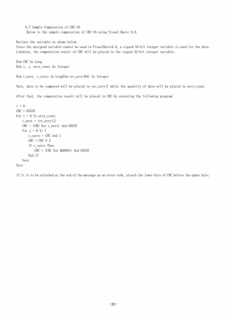
6.7 Sample Computation of CRC-16
Below is the sample computation of CRC-16 using (isual Basic 6.0.
Declare the variable as shown below.
Since the unsigned variable cannot be used in (isualBasic6.0, a signed 16-bit integer variable is used for the data.
Likewise, the computation result of CRC will be placed in the signed 32-bit integer variable.
Dim CRC As Long
Dim i, j, arry_count As Integer
Dim c_next, c_carry As LongDim crc_arry(64) As Integer
Next, data to be computed will be placed in crc_arry() while the quantity of data will be placed in arry_count.
After that, the computation result will be placed in CRC by executing the following program:
i = 0
CRC = 65535
For i = 0 To arry_count
c_next = crc_arry(i)
CRC = (CRC Xor c_next) And 65535
For j = 0 To 7
c_carry = CRC And 1
CRC = CRC \ 2
If c_carry Then
CRC = (CRC Xor &HA001) And 65535
End If
Next
Next
If it is to be attached at the end of the message as an error code, attach the lower byte of CRC before the upper byte.

- 24 -
6.8 Structure of ASCII Request Message (Data transmission from upper computer to this product)
■ See "6.1 Explanation about ASCII Codes" for codes from (a) to (g).
6.8.1 Structure of Read Request Message
6.8.2 Structure of Write Request Message
6.8.3 Structure of Save Request Message

- 25 -
6.9 Structure of ASCII Response Message (Data transmission from this product to upper computer)
■ See "6.1 Explanation about ASCII Codes" for codes from (a) to (g).
6.9.1 Response Message for Read Request Message
6.9.2 Response Message for Write/Save Request Message
6.9.3 Response Message for the Error

- 26 -
6.10 Explanation about ASCII Codes
■ The following codes from (a) Start Code, (b) Slave Address, up to (j) Error Type will be expressed in
ASCII code:
■ See "10. List of ASCII Codes" for the details about ASCII codes.
■ To convert into ASCII code, see the message structure in 6.8 and 6.9.
a) Start Code
It is a code that is necessary for the receiving side to detect the start of the message. It shall
be attached to the start of the character string to be sent.
b) Slave Address
It is an address of the device that will be communicated by the upper computer (this product).
The address in the response message from this product indicates the source of the response message.
c) Function Code
Enter the code 03H or 10H.
03H: If the data is to be read from this product
10H: If the data is to be written or saved into this product
d) Number of Registers
It specifies the number of registers that write. Since the number of registers of this product
is fixed to 2, set it to "0002H."
e) Register Address
It specifies the position of data to be read or written with two bytes.
See "10. List of Identifiers (Codes)" for the address of each command.
f) LRC
It is an error checking code for the detection of the possible error in the message. It sends LRC.
LRC that is used in this product is a value where all data in the message, except for start code
and end code, are summed up without performing a carryover and treat the sum total as the complement
of 2.
Any portion that is expressed as "1" and "B" shall be considered as "1BH."
See "6.12 Sample Computation of LRC" for the computation method of LRC.
If 12H was computed as an error code, attach "1" and "2" at the end of the message.
g) End Code
It is a code that is necessary for the receiving side to detect the end of the message. CR(0DH)
and LF(0AH) shall be attached at the end of the character string to be sent.
h) Number of Bytes
It specifies the number of registers that read and write x 2. Since the number of registers of
this product is 2 (fixed), set "04H."

- 27 -
i) Data Section
It specifies the data to be written into the register. Data is 4 bytes (fixed).
Data without decimal point will be written.
Example: In case of numerical data
Contents of Communication HEX Data Proportional Band (P) = 1. 0% 0000000AH
PV = 200.0P 000007D0H
SV = -10.00P FFFFFC18H
Example: ASCII code will be written in case of the character data (□ means space)
Contents of Communication HEX Data Priority Screen 0-1 = □INP 20494E50H
Priority Screen 0-2 = □MV1 204D5631H
Priority Screen 0-3 = □□P1 20205031H
j) Type of ERR
If there is an error in the message that was sent by the upper computer, the error number will
be included in the "response message" of this product for the reply.
Since error number "04" indicates the breakdown of measuring equipment (memory error, A/D
conversion error, or AT error), it will be included in the "response message" whether or not
there is an error in the "request message."
For multiple errors, the largest error number will be included.
Contents and classification of error are the following:
Error Number Description of errors in the "request message" that was received by this product 01 Received an unsupported function code
02 Specified register address has no data
03 Numerical value data is out of the "setting range that is specified individually
by the setting item" 04 Malfunction of measuring equipment (Memory error or A/D conversion error, AT error)

- 28 -
6.11 Things to Be Noted during ASCII Communication
6.11.1 Timing of Transmission
Upon using RS-485, set enough response delay time to ensure the communication (sending/receiving) with
the host computer.
See Figure of "6.1 Communication Procedures" and "5.8 Setting of Response Delay Time."
6.11.2 Request Interval
If the "request message" is to be sent continuously by the upper computer, wait for at least 2msecs. from
the arrival of the "response message" from this product before sending the next request message.
6.11.3 Conditions for Response
This product will not return the "response message" if start code and end code are not included in the
"request message."
Therefore, although there is an error in the "request message," the "response message" with NAK and error
code will not be returned unless the above condition is met.
Therefore, the upper computer should resend the necessary "request message" if the "response message" is
not returned within the reasonable time.
Once the start code is received, this product clears all codes that were received prior to the said start
code.
6.11.4 Address Specification Error
This product will not respond to any "request message" that specifies the address that is other than the
one that has been set to itself.
Therefore, if there is an error in the address section of the "request message," none of the slave stations
will return the "response message."
Therefore, the upper computer should resend the necessary "request message" if the "response message" is
not returned within the reasonable time.
6.11.5 Number of Digits of Data and Position of Decimal Point
See "6.10 Explanation about Codes (h) Numerical Data."
6.11.6 Operation After the Receiving of Save Request Message
This product starts the saving of data once it receives the save request message correctly from the upper
computer.
Only the data that is different from the one stored in the EEPROM (changed data) shall be saved.
Time that is required to save the data (TW) is within 6 seconds.
The product sends a message when the saving of data is completed.
Some data may be lost if the product is turned OFF while the saving process is in progress. Do not turn
the power of this product OFF for at least 6 seconds after the sending of save request message.
6.11.7 Upon Turning the Power ON
This product will not perform any communication for approximately 4 seconds after turning its power ON
(no response). Set the delay from power ON to start communication.
6.11.8 Saving the Data Other than Save Request Message
This product saves the parameter into the EEPROM even without receiving the save request message in case
of the following:
1) If the parameter is changed through key operation, it writes only changed parameters and
other related parameters. 2) If the auto tuning is activated and ended normally, only the PID constant will be written.
6.11.9 Change of Setting (alue (S( or S(2) by the Communication during Auto Tuning
If the value for control (S( or S(2) is changed via communication while the auto tuning is performed,
the said value (S( or S(2) will not be changed until auto tuning ends.

- 29 -
6.12 Sample Computation of LRC
Below is the sample computation of LRC using (isualBasic6.0.
Declare the variable as shown below.
Since the unsigned variable cannot be used in (isualBasic6.0, a signed 16-bit integer variable is used for the data.
Likewise, the computation result of LRC will be placed in the signed 16-bit integer variable.
Dim LRC As Integer
Dim i, arry_count As Integer
Dim lrc_arry(128) As Integer
Next, data to be computed will be placed in lrc_arry() while the quantity of data will be placed in arry_count.
After that, the computation result will be placed in LRC by executing the following program:
For i = 0 To arry_count
LRC = (LRC + lrc_arry(i)) And &HFF
Next
LRC = ((Not LRC) + 1) And &HFF
For example, if 12H was computed as an error code, attach "1" and "2" at the end of the message.

- 30 -
7. Specifications 7.1 Type of Communication Standard: EIA Standard Based on RS-485 7.2 Communication Specifications 7.2.1 Communication Method : Network・・・・・Multidrop System (1 to 31 stations) : Direction of Information・・・・・・・Half-Duplex : Synchronization System・・・・・・・Start-Stop Synchronization : Transmission Code・・・・・・・ASCII 7-bit Code (except for BCC data) (For 8-bit code, top bit = 0) 7.2.2 Interface System : Signal Wire・・・・・・・・・・・Two wires for sending and receiving : Communication Speed・・・・・・・・・1200, 2400, 4800, 9600, 19200BPS Select and set the above. : Communication Distance・・・・・・・・・Up to 500m However, the distance may vary depending on the surrounding
environment, such as cable. 7.2.3 Character
1) TOHO Communication Protocol : Start Bit Length・・・・・・・1 bit fixed : Stop Bit Length: Select and set from 1 bit and 2 bits : Data Length: Select and set from 7 bits and 8 bits : Parity・・・・・・・・・・・・・・・Select and set from none, odd, and even : BCC Checking・・・・・・・・・Select and set from Yes (with) and No (without) : Communication Address・・・・・・・・・・・1-99
2) MODBUS (RTU) Communication Protocol : Start Bit Length・・・・・・・1 bit fixed : Stop Bit Length: Select and set from 1 bit and 2 bits (With parity: 1 bit fixed) : Data Length・・・・・・・・・・・・・・・8 bits fixed : Parity・・・・・・・・・・・・・・・Select and set from none, odd, and even : CRC-16 Check・・・ON fixed : Communication Address・・・・・・・・・・・1-247
3) MODBUS (ASCII) Communication Protocol : Start Bit Length・・・・・・・1 bit fixed : Stop Bit Length: Select and set from 1 bit and 2 bits (With parity: 1 bit fixed) : Data Length・・・・・・・・・・・・・・・7 bits fixed : Parity・・・・・・・・・・・・・・・Select and set from none, odd, and even : LRC Check・・・・・・・・・ ON fixed : Communication Address・・・・・・・・・・・1-247 4) MODBUS (RTU/ASCII) Communication Function Code
: 03H (Read the content of the holding register) : 10H (Write the content of multiple holding registers)

- 31 -
8. Wiring
○ The figure below shows the example of the case where secondary stations 1–3 (3 stations) will be connected to the primary station. ◇ For cables ①-③, use the cable with the same characteristic impedance.
・Connect secondary stations 1-3 as slave, as shown in the figure.
Use the cable with the same characteristic impedance for the connection between secondary stations as
well.
◇ Attach the terminator to both the primary station ① and the farthest secondary station ② (secondary
station 3).
◇ Choose the terminator of which [Characteristic impedance of cables ①-③] = [Resistance of ①] =
[Resistance of ②].
・Also, use the cable with characteristic impedance where [Resistance of ①]//[Resistance of ②] (parallel
combined resistance) is 75Ω or higher.

- 32 -
9. List of Identifiers (Codes) ■ See the User's Manual of this product for setting range, selection items, initial value,
and other related information. a) Identifier: Symbol that expresses the item. Place this symbol in the identifier within the
message. Furthermore, "□" inside the frame indicates SP (ASCII code: 20H). b) Character: Character to be displayed on the display of the product c) Name: Name of the item d) R/W: Describe whether read or write is possible. Or describe if both read and write are possible. e) Explanation: Caution: "NAK2" will be responded for the R/W to the character that does not satisfy the display
condition. Example: If E(2 option is not selected, R/W to the character of E(2 will be "NAK2."
Iden-tifier
Relative Address
Absolute Address
Charac-ter
Name R/W Description
P(1 0000h 40001 Measuring (alue (P() R To be used as a monitor of measuring value (P() If Over Scale: HHHHH
S(1 0002h 40003 Set (alue (S() R/W R/W of Set (alue (S()
PR1 0004h 40005 Priority Screen Func-
tion Setting 1 R/W R/W of Priority Screen Function Setting
1 PR2 0006h 40007 Priority Screen Func-
tion Setting 2 R/W R/W of Priority Screen Function Setting
2 PR3 0008h 40009 Priority Screen Func-
tion Setting 3 R/W R/W of Priority Screen Function Setting
3 PR4 000Ah 40011 Priority Screen Func-
tion Setting 4 R/W R/W of Priority Screen Function Setting
4 PR5 000Ch 40013 Priority Screen Func-
tion Setting 5 R/W R/W of Priority Screen Function Setting
5 PR6 000Eh 40015 Priority Screen Func-
tion Setting 6 R/W R/W of Priority Screen Function Setting
6 PR7 0010h 40017 Priority Screen Func-
tion Setting 7 R/W R/W of Priority Screen Function Setting
7 PR8 0012h 40019 Priority Screen Func-
tion Setting 8 R/W R/W of Priority Screen Function Setting
8 PR9 0014h 40021 Priority Screen Func-
tion Setting 9 R/W R/W of Priority Screen Function Setting
9 INP 0016h 40023 Setting of Input Type R/W R/W of the Setting of Input Type P(G 0018h 40025 Setting of Gain of P( R/W R/W of the Setting of Gain of P(
P(S 001Ah 40027 Setting of Zero Point of R/W R/W of the Setting of Zero Point of P( PDF 001Ch 40029 Setting of Input Filter R/W R/W of the Setting of Input Filter □DP 001Eh 40031 Setting of Decimal Point R/W R/W of the Setting of Decimal Point
Without Decimal Point: 00000 With Decimal Point: 00001
□FU 0020h 40033 Function Key Function Settings
R/W R/W of the Setting of Function Key Function
LOC 0022h 40035 Key Lock Settings R/W R/W of the Key Lock Settings SLH 0024h 40037 Setting of the Maximum R/W RW/ of the Setting of the Maximum Limit SLL 0026h 40039 Setting of the Minimum R/W R/W of the Setting of the Minimum Limit □MD 0028h 40041 Setting of Control Mode R/W R/W of the Setting of Control Mode
Execution of Control: 00000 Manual Control: 00001 Stop the Control: 00002 Auto Tuning Is in Progress: 00003

- 33 -
Iden-tifier
Relative Address
Absolute Address
Charac-ter
Name R/W Description
CNT 002Ah 40043 Setting of Control Type R/W R/W of the Setting of Control Type DIR 002Ch 40045 Switching of Direct R/W R/W of the Switching of Direct Ac- M(1 002Eh 40047 Manipulated (ariable of R/W R/W of the Manipulated (ariable of
TUN 0030h 40049 Setting of Tuning Type R/W R/W of the Setting of Tuning Type ATG 0032h 40051 9. AT Coefficient R/W R/W of AT Coefficient ATC 0034h 40053 AT Sensitivity R/W R/W of AT Sensitivity □P1 0036h 40055 Setting of the Propor- R/W R/W of the Setting of the Proportional □I1 0038h 40057 Setting of Reset Time R/W R/W of the Setting of Reset Time □D1 003Ah 40059 Setting of Derivative R/W R/W of the Setting of Derivative Time □T1 003Ch 40061 Setting of the Propor- R/W R/W of the Setting of the Proportional ARW 003Eh 40063 Anti-Reset Windup R/W R/W of Anti-Reset Windup
MH1 0040h 40065 Maximum Limit of M(
Limiter R/W R/W of the Maximum Limit of M( Limiter
ML1 0042h 40067 Minimum Limit of M(
Limiter R/W R/W of the Minimum Limit of M( Limiter
□C1 0044h 40069 Setting of the Control R/W R/W of the Setting of the Control
CP1 0046h 40071 Setting of the OFF Point of Output 1
R/W R/W of the Setting of the OFF Point of Output 1
M(2 0048h 40073 Manipulated (ariable of R/W R/W of the Manipulated (ariable of
□P2 004Ah 40075 Setting of the Propor- R/W R/W of the Setting of the Proportional □T2 004Ch 40077 Setting of the Propor- R/W R/W of the Setting of the Proportional MH2 004Eh 40079 Maximum Limit of M(
Limiter R/W R/W of the Maximum Limit of M( Limiter
ML2 0050h 40081 Minimum Limit of M(
Limiter R/W R/W of the Minimum Limit of M( Limiter
□C2 0052h 40083 Setting of the Control R/W R/W of the Setting of the Control
CP2 0054h 40085 OFF Point of Output 2 Settings
R/W R/W of the OFF Point of Output 2
PBB 0056h 40087 Manual Reset R/W R/W of the Manual Reset □DB 0058h 40089 Setting of Dead Band R/W R/W of the Setting of Dead Band RP1 005Ah 40091 Setting of S( Ramp Time R/W R/W of the Setting of S( Ramp Time
RP2 005Ch 40093 Setting of S(2 Ramp Time R/W R/W of the Setting of S(2 Ramp Time
EIF 005Eh 40095 P( Event Output 1
Function R/W R/W of the P( Event Output 1 Function
E1H 0060h 40097 Maximum Limit of Event Output 1
R/W R/W of the Maximum Limit of Event Output 1
E1L 0062h 40099 Minimum Limit of Event Output 1
R/W R/W of the Minimum Limit of Event Output 1
E1C 0064h 40101 Event Output 1 Sensi-
tivity R/W R/W of the Setting of Event Output 1
Sensitivity E1T 0066h 40103 Event Output 1 Delay
Timer Setting R/W R/W of the Setting of Event Output 1
Delay Timer E1B 0068h 40105 Special Event Output 1
Function
R/W R/W of the Setting of Special Event Output 1 Function
E1P 006Ah 40107 Event Output 1 Polarity Settings
R/W R/W of the Setting of Event Output 1 Polarity
CM1 006Ch 40109 CT Input Monitor R R of CT Input Monitor CT1 006Eh 40111 Event Output 1 Current
Abnormality
R/W R/W of the Setting of Event Output 1 Current Abnormality

- 34 -
Iden-tifier
Relative Address
Absolute Address
Charac-ter
Name R/W Description
E2F 0070h 40113 P( Event Output 2 Function
R/W R/W of the Setting of P( Event Output 2 Function
E2H 0072h 40115 Maximum Limit of Event Output 2
R/W R/W of the Maximum Limit of Event Output 2
E2L 0074h 40117 Event Output 2 Minimum R/W R/W of the Minimum Limit of Event Output E2C 0076h 40119 Event Output 2 Sensi-
tivity R/W R/W of the Setting of Event Output 2
Sensitivity E2T 0078h 40121 Event Output 2 Delay
Timer Setting R/W R/W of the Setting of Event Output 2
Delay Timer E2B 007Ah 40123 Special Event Output 2
Function
R/W R/W of the Setting of Special Event Output 2 Function
E2P 007Ch 40125 Event Output 2 Polarity R/W R/W of the Setting of Event Output 2 CM2 007Eh 40127 CT Input Monitor R R of CT Input Monitor CT2 0080h 40129 Event Output 2 Current
Abnormality
R/W R/W of the Setting of Event Output 2 Current Abnormality
DIF 0082h 40131 Setting of DI Input R/W R/W of the Setting of DI Input Function DIP 0084h 40133 Setting of DI Polarity R/W R/W of the Setting of DI Polarity S(2 0086h 40135 Control Setting 2 R/W R/W of the Setting of Control Setting PRT 0088h 40137 Setting of Communica-
tion Protocol R/W R/W of the Setting of Communication
Protocol Dedicated Protocol: 00000 MODBUS (RTU): 00001
COM 008Ah 40139 Setting of Communica-
tion Parameters R/W R/W of the Setting of Communication
Parameters BPS 008Ch 40141 Setting of Communica-
tion Speed R/W R/W of the Setting of Communication
Speed ADR 008Eh 40143 Communication Address R/W R/W of Communication Address Setting AWT 0090h 40145 Setting of Response R/W R/W of the Setting of Response Delay MOD 0092h 40147 Switching of Communi-
cation Mode Settings
R/W R/W of the Setting of the Switching of Communication Mode RO: 00000
TMO 0094h 40149 Setting of Timer Output R/W R/W of the Setting of Timer Output TMF 0096h 40151 Setting of Timer Func- R/W R/W of the Setting of Timer Function H/M 0098h 40153 Switching of Timer Unit R/W R/W of the Switching of Timer Unit TS( 009Ah 40155 Timer S( Start Permis-
sion R/W R/W of the Setting of Timer S( Start
Permission Range TIM 009Ch 40157 Timer Time Setting R/W R/W of Timer Time Setting TIA 009Eh 40159 Timer Remaining Time R R of Timer Remaining Time Monitor TRF 00A0h 40161 Setting of Transmission R/W R/W of the Setting of Transmission
TRP 00A2h 40163 Direct Action/Reverse
Action of Transmission
R/W R/W of the Setting of Direct Ac-
tion/Reverse Action of Transmission
TRH 00A4h 40165 Setting of Transmission R/W R/W of the Setting of Transmission Output TRL 00A6h 40167 Setting of Transmission R/W R/W of the Setting of Transmission Output TST 00A8h 40169 Timer Start
/Stop R/W W of Timer Start/Stop
Start: 00001 Stop: 00000
OM1 00AAh 40171 Output Status Monitor R R of Output Monitor ①②③④⑤ ⑤ : OUT1 (1: ON 0: OFF) ④ : OUT2 (1: ON 0: OFF) ③ : E(1 (1: ON 0: OFF) ② : E(2 (1: ON 0: OFF)
EM1 00ACh 40173 DI Status Monitor R R of DI Monitor ON: 00001 OFF:00000

- 35 -
Identi-
fier Relative Address
Absolute Address
Charac-ter
Name R/W Description
□AT 00AEh 40175 AT Start/Cancel R/W R/W of AT Start/Cancel Start: 00001 Cancel: 00000
STR 00B0h 40177 Save Data W Save Data
Identifier that will be used only at the blind setting
Iden-tifier
Relative Address
Absolute Address
Charac-ter
Name L/B Description
000 SET0 L/B Blind: 00000 Do not blind: 00001
001 SET1 L/B Blind: 00000 Do not blind: 00001
002 SET2 L/B Blind: 00000 Do not blind: 00001
003 SET3 L/B Blind: 00000 Do not blind: 00001
004 SET4 L/B Blind: 00000 Do not blind: 00001
005 SET5 L/B Blind: 00000 Do not blind: 00001
006 SET6 L/B Blind: 00000 Do not blind: 00001
007 SET7 L/B Blind: 00000 Do not blind: 00001
008 SET8 L/B Blind: 00000 Do not blind: 00001

- 36 -
10. List of ASCII Codes
Up-
per
Lower 00h 10h 20h 30h 40h 50h 60h 70h
00h NUL DLE Space 0 @ P ` p
01h SOH DC1 ! 1 A Q a q
02h STX DC2 " 2 B R b r
03h ETX DC3 # 3 C S c s
04h EOT DC4 $ 4 D T d t
05h ENQ NAK % 5 E U e u
06h ACK SYN & 6 F V f v
07h BEL ETB ' 7 G W g w
08h BS CAN ( 8 H X h x
09h HT EM ) 9 I Y i y
0Ah LF SUB * : J Z j z
0Bh VT ESC + ; K [ k {
0Ch FF FS , < L \ l |
0Dh CR GS - = M ] m }
0Eh SO RS . > N ^ n ~
0Fh SI US / ? O _ o DEL
※How to Use the ASCII Code Table: (ASCII Code) = (Upper) + (Lower) Example 1: If "A": (41h) = (40h) + (01h)
Example 2: If "m": (6Dh) = (60h) + (0Dh)

- 37 -
TOHO ELECTRONICS INC. Main Office: 2-4-3 Nishi-Hashimoto, Midori-Ku, Sagamihara-Shi, Kanagawa-Ken 252-0131 Japan TEL: (042) 700-2100 (Representative Line) FAX: (042) 700-2112 Tokyo Office: 401 Palace Yoyogi Uehara, 3-1-8 Nishihara, Shibuya-Ku, Tokyo 151-0066 Japan TEL: (03) 5452-4010 (Representative Line) FAX: (03) 5452-4017 Osaka Office: 7F East Hall, Yachiyo Bldg., 2-1-21 Tenjinbashi, Kita-Ku, Osaka-Shi, Osaka 530-0041 Japan TEL: (06) 6353-9205 (Representative Line) FAX: (06) 6353-9273 Kumamoto Office: 2-10-23 Higashino, Higashi-Ku, Kumamoto-Shi, Kumamoto-Ken 861-2106 Japan
TEL: (096) 214-6507 (Representative Line) FAX: (096) 214-6510 4D-0148