operation manual - arcade-museum.com
TRANSCRIPT

•
•
a
TM
TEKKEN3 OPERATION MANUAL
LtCAUTION • Be sure to read this manual and the instruction manual for
cabinet to be used before installing and operating this game machine to ensure the safety and to operate correctly,
• Keep this manual with care so as to read in case of need in daily operation.

'. •

.
•
•
Table of Contents
Introduction
Table of Contents
1. Precautions on safety (for Safety Operation) ................................................................................ 1 1-1 Explanation for a symbol.1-. for calling attention: .......................................................... . 1 I -2 Explanation for signal words (.1-. WARNING, .1-. CAUTION) .................................... I
1-3 Precaution on Safety for operators in charge of Installation
(It should be handled by an engineer.) ..................................... .......................................... 2
1-4 Precaution on Safety for Operator in charge of Maintenance
(It should be handled by an engineer.)............................................................................... 3
1-5 Precautions on Safety with regard to Discard.................................................................... 3
2. Packing Substance Check .... .................. ............................... .......... ............................................... 4
3. Specifications ............................................................................................................................. 5
3-I Control Panel ..................................................................................................................... 5
3-2 Monitor ............................................................................................ .................................. 5
3-3 PC Board............................................................................................................................ 6 4. Installation .... ............................................................................... ................................ ....... ... 7'
5.
4-1 Connection to a Cabinet corresponding to JAMMA standard........................................... 7 4-1-1 Connection of Control Panel ............................................................... ................ 7 4-1-2 Connection of PC Board...................................................................................... 8 4-1-3 Connection of Spcaker ............. ........................................................................... 8
4-2 Connection to a Cabinet corresponding to JAMMA VIDEO standard (JVS) ................... 9 4-2-1 Connection of Control Panel ............................................................................... 9 4-2-2 Connection of PC Board ............... ......................................................... .............. 9
Adjustment ........................................... ................................................................ ............... ... 12 5-I Adjusting Switch ...................... ...... ..................................................................... .............. 12 5-2 TEST Mode ........................................................................................ ............................... 13
5-2- I DISPLAY TEST ....................................................................... ........................... 14
5-2-2 SWITCH TEST ................................................................................................... 18
5-2-3 SOUND TEST .......................................................... ........................... ................ 18
5-2-4 JVS CABINET OPTIONS ........................................... ............................ ........... 19
5-2-5 GAME OPTIONS ............................................................................................... 20 5-2-6 COIN OPTIONS ...................................................... ........................................... 22 5-2-7 A. D.S . .................................................................................................................. 23 5-2-8 DATA CLEAR ............................................................................................. ... .... 24
5-2-9 EXIT & SAVE (Exit of TEST mode) ...................................... ....................... .... 24 6. Maintenance (It must b.e handled by an engineer) ........................................................................ 25
7. Transportation .. ........................................................................................................................... 25
8. PC Board Edge Connector List ................................................................. ................. ............... .... 26
�WARNING
[Note]
Do NOT remodel this game machine without our agreement;
otherwise, an unexpected danger may happen.
• The contents on this operation manual are subject to change without notice for improvement.
I

Introduction
Thank you for purchasing OUf TEKKEN 3 (hereinafter mentioned as the game machine).
This manual shows you how to operate, install, transport, remove, maintain and discard this game machine in safety.
Be sure to read this manual and the instruction manual for cabinet to be used before installing and operating this game machine to ensure the safety and to operate correctly.
This manual applies to a staff of a game center. However, an article indicated as "It must be handled by an
engineer." applies to engineers, so the operation must be done by engineers only. Never someone else besides the engineer should operate it.
Engineer means the following personnel:
Personnel who had taken credits of mechanical or electrical engineering in university. college or highschool, or who have knowledge as same as one who had taken the above credits and also who maintains,
takes care and repairs amusement machines as a daily work. .
When an owner of this game machine leaves operation, installation, transportation, removal, maintenance and • discard to the other person� instruct himlher to read the articles in point and to follow the regulations.
Keep this manual with care so as to read in case of need in daily operation.
In case of resell of the game machine, be sure to attach this manual to the PC board.
For inquiries about the game machine and servicing: As for inquiries about the game machine and servicing for the machine. contact your distributor .
•
"

•
•
1. Precautions on safety (for Safety Operation)
1-1 Explanation for a symbol Lh for calling attention:
The meaning of the symbol .& for calling attention on this manual is as follows:
The symbol Lh for calling attention shows a potential danger and means not only an unspecified but general notice for dangers, warnings and cautions, All of notices indicated by this mark are concerned with safety.
1-2 Explanation for signal words (Lh WARNING, Lh CAUTION)
On this manual, these signal words ( &. WARNING, &. CAUTION) show a danger level for person and a damage level for property which have a possibility to occur.
.&:WARNING
�CAUTION
,
In the case that an operator would be killed or seriously wounded
if he/she makes a mistake in the operation.
In the case that an operator would be slightly wounded or that
only the property will be damaged if he/she makes a mistake in the
operation.
These levels mentioned above are as follows:
*. Classification for the damage
•
A serious wound: Loss of eyesight, an injury. a bum (by high or low temperature), an electrical shock, It a fracture of a bone or poisoning which �eaves an aftereffect and needs admission to a hospital or going to hospital for a long term for treatment.
Slight wound: A wound which does not need admission to a hospital or going to hospital for a long term for treatment. (A wound except for mentioned above.)
Property damage: Large scale damage relating to the building. property. livestock or pets .
•
- 1 -

1-3 Precaution on Safety for operators in charge of Installation
(It should be handled by an engineer.)
[Notice]
• This game machine corresponds to both of JAMMA standard and JAMMA VIDEO standard (JVS). The notice on safety differs with regard to installation because that the connecting procedures and others
differ depending on a standard. Be Sure to read the article corresponding to the standard after conftrming the standard for the cabinet by reading the manual for cabinet to be used.
<For a cabinet corresponding to JAMMA standard>
�WARNING
• Be sure to turn OFF the power of cabinet to be used before
installation and removal of PC board; otherwise, an operator
may be struck by electricity.
• Be sure to connect +5V (2.5A or more) and + 12V (2.0A or more correctly for power of PC board; otherwise, a wrong connection
may cause an accident, such as a fire, and trouble.
• The voltage should be used within the range of ± 5 % j otherwise,
an accident, such as a fire, and trouble may happen.
<For a cabinet corresponding to JAMMA VIDEO standard (JVS»
�WARNING
• Be sure to turn OFF the power of cabinet to be used before
installation and removal of PC board; otherwise, you may be
struck by electricity.
• Be sure to connect +5V (2.5A or more) correctly for power of
PC board; otherwise, a wrong connection may cause an accldeJil.. ;
such as a fire, and trouble. • • The voltage should be used within the range of±5%; otherwise,
an accident, such as a fire, and trouble may happen.
-2-

•
•
1-4 Precaution on Safety for Operator in charge of Mmntenance
�WARNING
(It should be handled by an engineer.)
• Do NOT remodel this game machine without our agreement;
otherwise, an unexpected danger may happen.
• Be sure to turn OFF the power switch of the cabinet before ·
maintenance work; otherwise, an operator or another one may
be injured or struck by electricity.
1-5 Precautions on Safety with regard to Discard
�CAUTION
• If this game machine is discarded, perform gathering,
transportation and disposal works in the procedure based on a
law.
• If an owner of this game machine leaves gathering,
transportation and disposal works for discard" to the other
person, entrust a professional with each operation •
! ,
- 3 -
•
•

•
2. Packing Substance Check
This game machine consists of the followings.
[Notice]
• Make sure that the following substances are complete.
Name Description Qt'y
Game PC board, "TEKKEN 3" System 12 PC board I
Operation manual This manual I
Title board Logo "TEKKEN 3" is described. 1
A sticker (.1) Oblong sticker for move list I
B sticker (.1) Oblong sticker for explanation of controls 1 Button seal (.1) 1 sheet printed for two players 1
Kick harness ("2) Wired 48P extension edge connector 1
*1) On the adhesive side of A sticker, B sticker and button seal, a "release type" bonding agent, which is hard to leave a mark after peeling it off, is used.
*2) This game machine corresponds to both of JAMMA standard and JAMMA VIDEO standard (JVS). The kick harness is not necessary if the PC board is connected to a cabinet corresponding to J AMMA VIDEO standard (JVS). (Refer to "3-3 PC Board" for connection terminal of each standard.)
. .
- 4-
•

•
•
3. 3-1
Specifications
Control Panel
2-P specifications • 8-direction lever: I x 2 • Button switch: 4x2 • Start switch : Ix2
PI-START switch
PI: 8-direction
lever
PI: Bulton
switch
•
P2-START switch
P2: Button
switch
3-2 Monitor
Direction of monitor: . Horizontal
Scanning retrace line format: I�terlace/non-iIlterlace: selectable
Synchronizing signal: Composite/separate : selectable ('() Horizontal synchronizing frequency: 15.75 kHz Vertical synchronizing frequency: 60.0 Hz
*1) Only for connection of cabinet corresponding to JAMMA VIDEO standard (JVS)
- 5 -
•
•
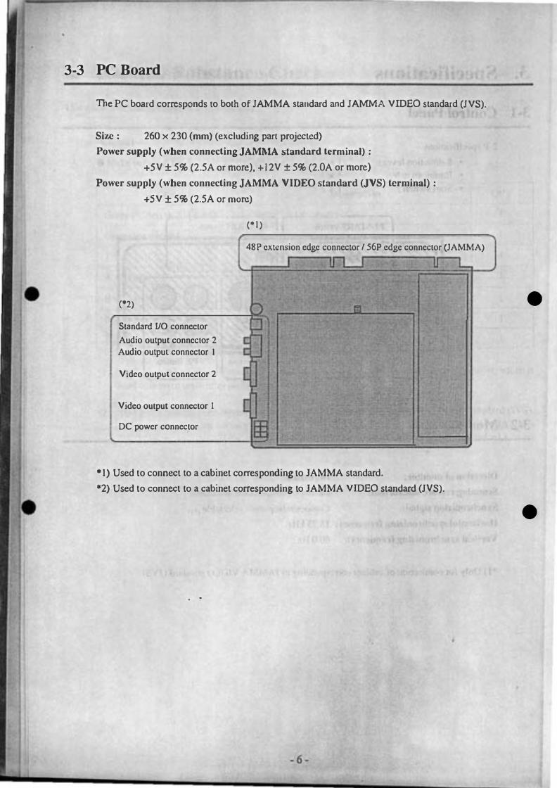
3-3 PC Board
The PC board corresponds to both of JAMMA standard and JAMMA VIDEO standard (JVS).
Size: 260 x 230 (mm) (excluding part projected)
Power supply (when connecting JAMMA standard terminal) :
+5V ± 5% (2.5A Or more), +12V ± 5% (2.0A or more)
Power supply (when connecting JAMMA VIDEO standard (JVS) terminal) :
+5V ± 5% (2.5A or more)
('1)
48P extension edge connector 156P edge connector (JAMMA)
U l .J u
('2) � m Standard UO connector
�o Audio output connector 2 Audio outpul connector I
Video outpUI connector 2 [ Video output connector I [ " I,· DC power connector I . . '
'1) Used to connect to a cabinet corresponding to JAMMA standard.
'2) Used to connect to a cabinet corresponding to JAMMA VIDEO standard (JVS).
. .
- 6 -
L
j
•
•

•
•
4. Installation
[Notice)
• This game machine corresponds to both of JAMMA standard and JAMMA VIDEO standard (JVS). Be sure to read the article corresponding to the standard afler confinning the standard for the cabinet by reading the manual for cabinet to be used.
• The m mark is indicated on the anicle for cabinet corresponding to JAMMA standard, and the !m mark is indicated on the mic1e for cabinet corresponding to JAMMA VIDEO standard (JVS).
4-1 Connection to a Cabinet corresponding to JAMMA standard m
[Notice)
Use + 12V or less for line voltage of coin counter .
4-1-1 Connection of Control Panel m • Connect the JAMMA edge connector and kick harness (wired 4SP extension edge connector) packed together to each appropriate switch of control panel with reference to "S. PC Board Edge Connector List".
[Notice)
• Be sure to use a JAMMA standard conformable one and a specified one for the JAMMA edge connector. • Be sure to use a NAMCO specified one (OOK-made: 2250-IOO24C2-2312) for the 4SP extension edge
connector. • Do not connect anything to the blank column on "S. PC Board Edge Connector List" • Connect each switch and lever input of edge connector to N. O. tenninal, such as micro switch and etc. • Be sure to connect the COM tenninal to GND of edge connector for the micro switch wired .
- 7 -
, .
•

•
•
4-1-2 Connection of PC Board m
&.WARNING
• Be sure to turn OFF the power of cabinet to be used before
installation and removal of PC board; otherwise, an operator may be struck by electricity.
• Be sure to connect +SV (2.5A or more) and +UV (2.0A or more)
correctly for power of PC board; otherwise, a wrong connection
may cause an accident, such as a fire, and trouble.
• The voltage should be used within the range of±S%; otherwise,
nn accident, such as a fire, and trouble may happen.
After selling the PC board in the cabinet. connect the JAMMA edge connector and 48P extension edge connector correctly .
4-1-3 Connection of Speaker m
Connect the speaker tennina] of the JAMMA edge connector to the (L) side speaker, and connect the speaker (R) lennin.l of the kick harness (wired 48P extension edge connector) to the (R) side speaker with reference to "S. PC Board Edge Connector List"
[Notice)
• If the monaural cabinet is used in stereo mode, the sound of only left side is output. The sound of the game machine is the stereo specification on delivery. Select "MONAURAL" in TEST mode (Refer to "5-2 TEST mode".) if the cabinet to be used is monaural one .
• Be sure to use a NAMCO pecified one (DDK·made: 225D·IOO24C2·23l 2) for the 4SP extension edge connector .
•
•
. .
- 8 -
•

•
•
4-2 Connection to a Cabinet corresponding to JAMMA VIDEO
standard (JVS) �
4-2-1 Connection of Control Panel �
After being sure to read the manual for cabinet to be used, connect the suitable contro.l panel for this game machine (Refer to "3·1 Control Paner·.) to the cabinet.
4-2-2 Connection of PC Board �
�WARNING
• Be sure to turn OFF the power of cabinet to be used before installation and removal of PC board; otherwise, you may be
struck by electricity.
• Be sure 10 connecl +5V (2.5A or more) correclly for power of
PC board; othenvise, a wrong connection may cause an accident., such as a fire, and trouble.
• The voltage should be used within the range of±5%i otbcrwisc, an accident, such as a fire, and trouble may happen.
After being sure to. read the manual for cabinet to be used. connect the PC board according to. the following procedures. Referto "S·I·3 Replacement of game PC board" on the instruction manual for "CYBERLEAD" if the "CYBERLEAD" made by NAMCO is used as a cabinet.
(I) Open the PC board loading section of cabinet. If another PC board has been already connected, remove it.
(2) Install the PC board for this game machine in the PC board loading section correeLly so Llmlthe cable becomes easy to be connected. (The following figure shows the case that the cabinet "CYBERLEAD"
made by NAMCO is used.)
- 9 -
•
•

(3) Connect the cable at cabinet side to the concerned connector on the PC board correctly. (Refer to figure below.)
Cable at cabinet side
• Cable: Sectional terminal is I!!!!!! (Standard 110)
• Cable: Sectional terminal is 0 (Audio)
• RED or "R": to one of red terminals • WIDTE or "L": to one of while tenninals
• Cable: Sectional tenninal is (:-:.:.:-:) (Video)
• Possible to connect to both of them.
• Cable: Sectional tenninal is i:I:M (power)
(4) Close the PC board loading section of cabinet.
[Notice]
I '"IllKKEN 3" game PC board (Side)
o o
[JJJ RED WH1TE
•
• It is allowed to display the original messages and graphics, which are linked with the game conteAlI the game machine, on the LED dot-matrix display only if the game machine is used with the cabinet "CYBERLEAD" made by NAMCO. For that purpose, it is necessary to transmit the graphic data to Ul. cabinet in advance. If the original graphic data of the game machine is not transmitted, the following screen is displayed before displaying the game screen when turning ON the power of cabinet. (If the data has been already transmitted, it is not displayed. The mode is shifted to the game mode immediately.)
- JO-

Transfer LED data?
YES NO
$CklClirlg"YES" or "NO" by moving Ihe PI :S-direclion lever up and down, seule il wilh PI-B UrrON ;1!lIOlnalicaJJy seuled after 10 seconds approximalely even if the PI-BUTTON I is nOI pressed. In
item displayed in red is supposed to be selected. • selecte� the transmission is not pcrfonned, and thcn lhe screen above is displayed again when
ON the power at the next time.
is selected, the following screen is displayed, and then the data transmission is performed:
Finish
BUTTON 1 & START
Display of the progress oftr.lnsmilting operation
(Finish at the right cnd.)
Display how to interrupt the d:ll., tr.lnsmission.
•
mode is shifted after finishing the data transmission. The original display of the game on the LED dot-matrix display. After that, it is not necessary to transmit the dala again
[.EJD display dala in cabinel is initialized (Refer to "6-1-3 Explanalion of display contenls and it" on the instruclion manual "CYBERLEAD".), or unless the data transmission of another
perfomed. lf the PI-BUTION I and PI-START swilches are pressed al the same lime the data transmission, the operation is inlcmJpted, and then the usual game mode is shifted.
is necessary to transmit the data again whcn turning ON the power at the next time in order ;dIc: ol,;ginal display of Ihe game mach in on the LED dOl-matrix display.
- 1 1 -

•
5. Adjustment
5-1 Adjusting Switch
The adjusting switch on the PC board is as follows:
(I) Optional switch This switch is a pair of two units. If the # I is "ON", the mode is in TEST mode. If the #2 is "ON", the screen is in STOP. All of switches is usually "OFF".
[Notice]
• The nonnal game is not allowed to be perfonned if the optional switch #2 is in "ON" state .
(2) Speaker volume Turning it clockwise, the volume of spenker becomes large. Turning it counterclockwise, the volume of speaker becomes small.
[Notice]
• The spenker volume can not work for volume adjustment, if the cabinet corresponding to JAMMA VIDEO standard (JVS) is used. After being sure to read the manual for cabinet to be used, perform volume setling at cabinet side.
Speaker volume Optional switch
•
•
- 12 -

5-2 TEST Mode
- - - - � � -- - - --
I.fthe TEST switch is turned "ON" while displaying Ihe game screen, the mode is in TEST mode, and then the tcst menu screen is displayed. Use the rest switch on the cabinet (Refer to "S. PC Board Edge Connector List" to perform connection.) or the optional switch on the PC board. (Refer to "5-1 Adjusting switch".) Afler selecting an item (displayed in red) on the lest screen by moving the PI :8-direction lever up and down, press the PI-BUTl'ON I to display the selected test screen.
[Notice]
• The "JVS CABrNET OPTIONS" is not allowed to be selected if the PC board is connected from the JAMMA edge connector. It is allowed to be selected only if the PC board is connected from the connector corresponding to JAMMA VIDEO standard (JVS).
When exiting the TEST mode, be sure to select "EXIT & SAVE" from the test menu screcn as below before pressing PI-BUTTON I to end it.
DISPLAY TEST
SWITCH TEST
SOUND TEST
JVS CABINET OPTIONS
GAME OPTIONS
COIN OPTIONS
A.D.S.
DATA CLEAR
EXIT & SAVE
DISPLAY TEST ..................... � .. (5-2-t)
SIVITCH TEST .......................... (5-2-2)
SOUND TEST .. ................. � ... � ... (5-2-3)
IVS CABINET OPTIONS .� ....... (5-2-4)
GAME OPTIONS ...................... (5-2-5)
COIN OPTIONS ..... � ... � .............. (5-2-6)
A.D.S� .. �� ..................................... (5·2-7)
DATA CLEAR .......................... (5-2-8)
EXIT & SAVE (Exit oiTEST mode)
....................................... � ... � ........ (5-2�9)
•
• [Notice]
• If the procedure above is nollised for exiting of TEST mode, a changed setting may not be reflected correctly. Be sure to select "EXIT & SAVE·' from the test menu screen before pressing PI-BUTTON I to end it.
.In both cases that the test ;witch on the cabinet is the slide type and that the optional switch #1 on the PC board is used, take note of the followings .
• The mode enters the TEST mode when switching the test switch on the cabinet or thCroptionai switch # I on the PC board to ON from OFF. [f t.he switch has been turned ON before the mode enters TEST mode, tum it O N again after turning it OFF once .
• The test mode is not exited even if the test switch is turned OFF. Be sure to select "EXIT & SAVE" from the test menu screcn before pressing PI-BUTTON I to end it.
- 13 -

•
•
5-2-1 DISPLAY TEST
This mode perfonns test and setting on the screen display.
The DISPLAY TEST provides I kind of common display and 3 kinds of test pattern.
(I) COLOR EDIT This screen performs balance adjustment for brightness and color tone of display signal output from the PC board.
(2) DIAGONAL
This scrcen is used for display check in interlace mode.
(3) COLOR BAR This screen is used for balance check and adjustment for brightness and color tone.
(4) CONVERGENCE This screen is used for check and adjustment for display size, display position, ratio length to breadth and distortion.
The screen (I), which is the common display, is displayed so as to overlap on the screens (2) to (4). Press
PI-BUTTON 3 to select if screen (I) is displayed or not.
The screens (2) to (4) are the test display. The screen (2) is displayed immediately after entering DlSPLA Y • TEST mode. Press PI-BUTTON I to select the screen in order of (2), (3), (4) and (2) repemcdly. Pressing PI-START switch, the DISPLAY TEST mode exits and then the test menu screen appears.
(I) COLOR EDIT
This screen performs balance adjustment for brightness and color tone of display signal output from the PC board.
Non Interlace
Contrast:
Bright R:
Bright G: Bright B:
PREVIOUS VALUE, Pi-BUTTON 4 EXIT COLOR EDIT, Pi-BUTTON 3
NEXT COLOR TEST, Pi-BUTTON 1
EXIT, Pi-START
Scanning retrace line rormal on monitor
Whole contrast
Brightness (RED) Brightness (GREEN)
Brightness (BLUE)
Display how to return a vulue to the initia.l value.
Display how to exillhc COLOR EDIT mode.
Display how to advance to the next test pattern.
Display how to return to the tcst menu screen.
The above screen appears while overlapping on the test pattern.
•
After selecting an item to be changed by moving the PI :S-direction)ever up and down, move it right and
left to change the setting.
Pressing PI-BUTTON 4, all of contents changed on the COLOR EDIT screen are canceled.
Pressing PI-BUTTON 3, the COLOR EDIT screen is suspended, and then the display of setting items disappear.
Pressing PI-BUTTON 3 once again, the setti.ng items are displayed again, and th,'ll the COLOR edit screen becomes available.
Pressing PI-START switch, whole DISPLAY TEST exits, and then the test menu screen appears.
- 14 -

•
•
(2) DIAGONAL This screen is used for display check in interlace mode. _I
DIAGONAL
ENTER COLOR EDIT: Pl-BUTTON 3
NEXT COLOR TEST: Pl-BUTTON 1 EXIT: Pl-START
The diagonal pattern is displayed on the screen.
Display how '0 cn.er .hc COLOR EDIT mode. Display how to advance to the next test patlcrn. Display how to rcturn to the test menu screen.
Press PI -BUTTON 2 '0 selcc •• he color of diagonal pallem in order of WHITE, BLUE, RED, VIOLET. GREEN, LIGHT BLUE, YELLOW, BLACK and WHlTE repealedly.
Press PI-BUTTON I 10 swi.ch .he mode .o .he nex' 'eSl pallem (COLOR BAR).
Press I' I-B UTTON 3 '0 select if .he COLOR EDIT screen is displayed or nOlo (Referlo "( I) COLOR EDIT" on .his anicle.) Pressing PI-START swi.ch, the D ISPLAY TEST exilS. and then 'eSlmenu screen "ppears.
[Notice]
• T his test pattern is mainly used to check the screen display in interlace mode (_(). TIle interlace mode allows '0 display more preeise than .he non-interlace mode t'2)' However, .he screen may no' be displayed correctly depending on the moni.or .o be used due.o its properly. If the errors, such as dispersion of diagonaJ. severe nickering on the whole screen and etc .. appear on the screen above in interlace mode,
•
use it after switch the mode to "Non-interlace" from "Interlace" in the COLOR EDIT screen. (Refer to. "(I) COLOR EDIT" on this anicle.)
·1) Interlace mode This display mode allows to do double vertical resolution without change of horizonmllvertical frequencies if the display position of only half line is shifted in vertical direction intentionally once of twice screen displays, TIlis mode allows to display more precise and more smooth curved and straight lines than the noninterlace mode. (111e "CYBERLEAD" made by NAMCO provides the interlace mode as standard setting.)
·2) Non-interlace mode This display mode shows the routine screen display at the fixed position against "Interlace modc",
- 15 -

(3) COLOR BAR This screen is used for balance check and adjustment for brightness and color lone.
COLOR BAR
ENTER COLOR EDIT, Pl-BUTTON 3 NEXT COLOR TEST, Pl-BUTTON 1 EXIT, Pl-START
The color bar with brightness gradation is displayed.
COLOR BAR (WHITE)
COLOR BAR (RED)
COLOR BAR (GREEN)
COLOR BAR (BLUE)
Display how to enter lhe COLOR EDIT mode.
Display how to advance to the next test pattern.
Display how to return to the tcst menu screen.
Press P I-BUrrON 2 to select the phase of gradation in order of32, 16, 8, 4, 2 and 32 repeatedly.
Press PI·BUITON I to switch the mode to Ihe next tesl pattern (CONVERGENCE).
Press PI ·BUITON 3 to select if the COLOR EDIT screen is displayed or nol. (Refer to "(I) COLOR EDIT" on this article.)
Pressing PI·START switch,the DISPLAY TEST exits, and then lesl menu screen appears.
•
•
, '
. 16·
., ,

•
•
(4) CONVERGENCE
This screen is used for check and adjustment for display size. dispJay position, ratio length to breadth and distortion.
CONVERGENCE
I 1 1 -11 ENTER COLOR EDIT:- Pi-BUTTON 3 NEXT COLOR TEST: Pi-BUTTON 1 EXIT: Pi-START
CROSS HATCH PATTERN
Display how to enter the COLOR EDIT mode.
Display how to advance to the next test pattern.
Display how to return to the test menu screen.
The cross pattern called as "Cross hatch pattern" is displayed on the screen.
Press PI-BUTION 2 to select the color of cross hatch pattern in order of WHITE, BLUE, RED, VIOLET, GREEN, LIGHT BLUE, YELLOW, BLACK and WHITE repeatedly.
Press PI-BUTION I to switch the mode to the next test pattern (DIAGONAL).
Press PI-BUTION 3 to select if the COLOR EDIT screen is displayed or not. (Refer to "(I) COLOR
EDIT" on this article.)
Pressing PI-START switch, the DISPLAY TEST exits, and then test menu screen appears .
. .
- 17 -
•
•

•
•
5-2-2 SWITCH T�T
11tis mode performs test for switches connected to PC board, such as buttons on the conlrol panel. Pressing PI-BUTTON 3 and 4 allhe same lime. the lCSl menu screen appears.
S'IITCH TEST
•
••• •••
SERVICE:OFF
TEST S\1,OFF
DIP SWLOFF
DIP S\'l2:0FF
EXIT, P1-BUTTON 3 & 4
5-2-3 SOUND TEST
•
• • • ••
COIN 1, a COIN 2, a
-
-= (The display is changed according to input.)
Display how to return to the ICSt menu screen.
This mode performs sound oulPUllCSl and speaker selling (MONAURAUSTEREO).
Move PI :8-direction lever righl and lefllo change lhe number of sound.
Press PI-BUTTON I 10 play back lhe sound numbered on lhe display.
P ress PI-BUTTON 210 selecllhe mode STEREO/MONAURAL.
Play back lhe sound number 001 for the stereo OUlpUl leSI.
Pressing PI-START SWilCh, lhe lesl menu screen appears.
SOUND TEST
SONG,
STATUS:
[000 J 0000
SPEAKER OUT, STEREO
Sound number
The status of sound output
Presenl mode (STEREOIMONAURAL) selling
status
SET -MONAURAL", P1-BUTTON 2
Display h OW.lO changc the mode (,STEREO/
MONAURAL).
EXIT P1-START Display how to return to the test menu screen.
- 18-
•
•

•
•
5-2-4 JVS CABINET OPTIONS
This mode perfonns selling for cabinet corresponding to JAMMA VIDEO standard (JVS).
JVS CABINET OPTIONS
<DEFAULTS IN GREEN>
VIDEO SYNC: Composite
Main
1/0 1
I/O 2
JAl·ll·1A VIDEO STANDARD
[STEP 1)
EXIT: P1-START
[Notice]
- (a)
1-
1-
Display with regard to Ihe
JAMMA VJDEO standard
(NS)
• This article is not available if the cabinet is connected from the JAMMA edge connector on the PC board.
Press PI·BUTTON I to change the setting.
Pressing PI-START switch. the selting screen exits, and liten test menu screen appears .
(a) VIDEO SYNC (Synchronizing signal output fonnat of video output)
Composite (Composi\(: s)'flchroniz.:uion) Scpmuc (Vcrtic:illborizont.31 synchroni:t3.lion) i Thick frnme: initiru value
[Notice]
• If the VIDEO SYNC is set·at "Separate". the picture becomes more clear than "Composite". • As for use of cabinet "CYBERLEAD" made by NAMCO. set the VIDEO SYNC at "Composite" if an
apparatus is connected to the line output display terminal at rear side. (Refer to "4-4 Explanation of external VO tennin.l" on the instruction manual "CYBERLEAD".) .
. 19·
•
•

•
•
5-2-5 GAME OPTIONS
This mode perfonns setting with regard to the contents of game. such as difficulty level of game and eiC.
GAME OPTIONS <DEFAULTS IN GREEN>
(a) DIFFICULTY LEVEL, MEDIUM (b) FIGHT COUNT <lP GMIE> , 2 (c) FIGHT COUNT <VS GMIE>, 2 (d) LIFE BAR <lP GMIE>, 110 (e) LIFE BAR <VS GMIE>, 140 (I) GUARD DAMAGE, OFF (g) NEUTRAL GUARD, ON (h) ROUND TIME, 40 SEC.
(i) CHARACTER CHANGE AT COUNTINUE, YES
(j) CHARACTER CHANGE AT VS GMIE, NO
�) MUSIC IN ATTRACT, YES (I) EVENT MODE, OFF
(m) HIT COLOR, RED
EXIT, Pl-START
After selecling an ilem 10 be changed by moving Ihe PI :S·direclion lever up and down, press Ihe PIBUTION I 10 change Ihe seuing.
Pressing PI -START switch, the setting screen exits, and then test menu screen appears.
(a) DlFFlCUL TY LEVEL (Difficully level of game)
EASY MEDIUM HARD VERY HARD ULTRA HARD
t Thick frame: initial value (The rest is the same) (b) FIGHT COUNT <IP GAME> (Round number required for viclory al I-player game)
2 3 4
(c) FIGHT COUNT <VS GAME> (Round number required for viclory al vs game)
2 3 (d) LIFE BAR <I P GAME> (Life gauge al I-player game)
·2 . ·'1 NORMAL
(e) LIFE BAR <VS GAME> (Life gauge al vs game)
·2 ·1 NORMAL
(I) GUARD DAMAGE (Damage al guard)
ON (a little) OFF (non.)
4
+1
+1 "
(g) NEUTRAL GUARD (Guard io the condition Ihal lhe lever is 001 be lilled.)
ON (exist) OFF (none)
- 20-
5
5
+2
+2 , I
•
•

•
•
(h) ROUND TIME (Time per I round [second])
20 SEC. 30 SEC. 40 SEC. 50 SEC. 60 SEC.
(i) CHARACTER CHANGE AT CONTINUE (Change of character at continue)
NO (impossible)
(j) CHARACTER CHANGE AT VS GAME (Change of character on the player who is being challenged at vs game)
(k) MUSIC IN A TIRACT (Sound in altract)
YES (possible)
(I) EVENT MODE (process after vs game)
NO (impossible)
NO (impossible)
ON (Both or them: game over) OFF (Winner: continue t·player game)
(m) HIT COLOR (Red display effect at hit) �I --------�---r------------� .
RED (exist) GREEN (changed to another color) •
•
,
- 21 -

5-2-6 COIN OPTIONS
(a)
(b)
(c)
(d)
(e)
• (I)
(g)
•
This mode perfonns setting with regard 10 the game fees. such as Ihe credil number required for I play.
COIN OPTIONS <DEFAULTS IN GREEN>
START COST : 1 COIN TO START I ' CONTINUE COST : 1 COIN TO CONTINUE
COIN CHUTEl MECHANICAL VALUE : 1 COIN COUNT AS 1 COIN
COIN CHUTE2 MECHANICAL VALUE : 1 COIN COUNT AS 1 COIN
CREDIT MODE :
COMMON COIN COUNTER :
1 COUNTER FREE PLAY :
NO
EXIT: Pl-START
After selecting an ilem to be changed by lIloving the P I : 8-direction lever up and down. preSs Ihe PIBUTION I to change the selting.
Pressing PI -START SWilCh, the seuing screen exits. and Ihen test menu screen appears.
[Notice)
• It is impossible to change ilems (a) 10 (I) if "YES" has been sel in (g) FREE PLAY . • If the cabinet corresponding to tl,e JAMMA VIDEO slandard (JVS) is used for the game machine. items
(e) and (I) are set automatically as an initial value so as 10 be suitable for Ihe connection fonnal on Ihe cabinet. In this case, items (e) and (I) are not allowed to be changed.
(a) START COST (Number of coins required for I new play)
I I I 2 I 3 I 4 I 5 I 6 I 7 I 8 I 9 I COIN (S)TO START i Thick frame: initial value (The rest is the same)
. .
(b) CONTINUE COST (Number of coins required for I conlinue)
I I I 2 I 3 I 4 I 5 I 6 I 7 I 8 I 9 I COIN (S) TO CONTINUE
[Notice)
-.
• It is impossible to set (b) CONTINUE COST at the larger value Ihan (a) START COST.
,
(c) COIN CHUTE I MECHANICAL VALUE (Number of coins added when the coin swilch I works once)
I COIN COUNT AS I I I 2 I 3 I 4 I 5 I 6 I 7 I 8 I 9 I COIN
- 22 ·

•
•
(d) COIN CHUTE 2 MECHANICAL VALUE (Number of coins added when the coin switch 2 works once)
t COtN COUNT AS I t I 2 I 3 I 4 I 5 I 6 I 7 I 8 I 9 I COIN
(e) CREDIT MODE (Memory of credit)
COMMON (Inc calculation is performed from one
common credit in the both cases eyen if every coin switch works. and if every start switch is pressed.)
[Notice]
EACH ONE (PI nJld P2 have. credits sepamtcly.
Tllc coin switch I corresponds 10 PI side, and the coin switch 2 corresponds to P2 side respecth·cly.)
• Check if Ihe coin switch 2 is connected correctly when setting (e) CREDIT MODE to "EACH ONE";
otherwise. a coin may not be accepted at P2 side and the play may nOt be aV:1ilable.
(I) COIN COU TER (Assignment of coin counter)
t COUNTER (Used I coin counter common 10 two
coin switches)
[Special article]
2 COUNTERS (Used each coin COUnicr (or two coin
switches rcspeclhcly)
• 1" the case that a cabinet, which provides each I pair or coin switch and coin counter for P I side and P2 side respectively. is used:
Setting (e) CREDIT MODE above to " EACH ONE", (I) COIN COUNTER to "2 COUNTERS" after
checking each one is connected correctly. each coin counting at PI side and P2 side is allowed to be
logged scparately,
(g) FREE PLAY (Free play setting)
YES (free charge) NO (chnrge)
5-2-7 A.D.S .
This mode allows to read the data with regard to the past play results, such as total play time by this time
and etc,
Press P I -BUTrON I to sclect th. display screen,
Pressing PI-START switch, the test menu screen appears.
- 23 -
•
•

•
•
5-2-8 DATA CLEAR
This mode performs clear for the data which is stored even if the power is turned OFF.
BACKUP DATA CLEAR
CANCEL ADS DATA CLEAR RllNKING CLEAR SET DEFAULTS ALL OPTIONS ALL CLEAR
EXIT , Pl- START
Return to the test menu screen.
Clear A.D.S data only.
Initialization of ranking dut.a.
Initializmion of all options.
Clear all of data logged.
Display how to return to the test menu
screen.
After selecting an item by moving the P I oS-direction lever up and down, press the PI -BUTrON I to
perform the selected item.
Pressing P I-START switch, the t st menu screen appears.
( I) CANCEL Return to the lest menu screen.
(2) ADS DATA CLEAR Clear A.D.S data only. (Refer to "5-2-7 A.D.S ... . )
( 3 ) RANKING CLEAR (Initialization of ranking data)
Initialize aU of ranking data, such as straight victories records and etc .• at the value on delivery at
factory.
(4) SET DEFAULTS ALL OPTIONS (Initialization of all options)
Initialize all options set in TEST mode. (Refer to "5-2 TEST mode".)
(5) ALL CLEAR Perform the items (2) and (3) above at the same time.
5-2-9 EXIT & SAVE (Exit of TEST mode)
This mode returns to the game screen after exiting test mode.
[Notice]
e lf the exit of TEST mode is not performed in the correct procedur.es. a cbanged selling may not be
renccted correctly. Be sure to selcct "EXIT & SA YE" from the test menu screen before pressing P I
BUTrON I to end it.
- 24 -
•
•

6. Maintenance (It must be handled by an engineer)
7.
,&WARNING
[Notice]
o Do not remodel this game machine without our agreement;
otherwise, an unexpected danger may happen.
(;) Be sure to turn OFF the power switch of the cabinet before
maintenance work; otherwise, an operator or another one may
be injured or struck by electricity.
o Be sure to use a JAMMA standard confonnable one and a specified one for the JAMMA edge connector. o Be sure to use a NAMCO specified one (OOK-made: 2250-10024C2-2312) for 48P extension edge
connector (*1)
The tests for switch. sound and display should be performed periodically to use t.his game machine in the correct condition. (Refer to "5-2 TEST mode".)
The running in the condition that the PC board is in loose fixing and connecting may cause a trouble or malfunction. Check the PC board periodically because that it is loosened due to vibration during play.
An alien factor and dust on the PC board may cause a trouble or malfunction. Clean the PC board periodically to keep it neat.
[Notice]
o Be sure to turn OFF the power of cabinet before cleaning. Be sure to use an anti-static electricity cleaning tools, such as anti-static electricity brush for OA apparatus and etc.
If this game machine does not work correctly, check again that this game machine is installed and set correctly after reading the instruction manual for cabinet and this manual.
If the game machine does not work correctly after all efforts, contact your distributor after turning off the power of cabinet and removing the power plug from the outlet.
[Notice]
o Do NOT perfonn continuity test through tester: otherwise, the internal voltage of tester may destroy the Ie.
*1) The JAMMA edge connector and 48P extension edge connector are used for only cabinet corresponding to the JAMMA standard.
Transportation
When sending PC boards due to transfer, resale and repair, wrap them with sponge or bubble wrap, and pack them
in a card board boxes to protect against any shock from the outside.
- 25 -

8. PC Board Edge Connector List
[Notice]
• Refer to the following list when connecting this game machine to the cabinet corresponding to the JAMMA standard. It is not necessary for cabinet corresponding to the JAMMA VID EO standard (JVS) .
• Be sure to read the concerned item on "4. Installation" when connecting it.
JAMMA edge connector (561' 3.96mm pitch) Extension edge connector (481' 2.54mm pitch)
Soldering side Terminal No. Component side Soldering side Terminal No. Component side
GND A I GND Speaker R (.) AI B I Speaker R (+)
GND B 2 GND (Yellow( rOrange(
+5V C 3 +5V A2 B1
+5V D 4 +5V A3 83
E 5 A4 B4
.12V F 6 +12V Mis-insertion A5 B5 Mis-insertion prolection key protection key
Mis-insertion H 7 Mis-insertion A6 B6 protecLion key protcclion key
Coin counter 2 J 8 Coin counter 1 A7 B7
K 9 P2·BUTTON 3 AS B8 P2·BUTTON 4 [White. blue) [White, violet]
Speaker (-) L 10 Speaker(+) A9 B9 GND [Black)
Audio (GND) M I I Audio (+) AIO 8 1 0 GND (Black]
Video (GREEN) N 12 Video (RED) Al l B I I
Video (SYNC) P 13 Video (BLUE) AI2 8 1 2
Service switch R 14 Video (GND) AI3 B I 3
S IS Test switch AI4 BI4
Coin switch 2 T 16 Coin switch 1 AIS BI5
P2·START U 17 P I-START switch AI6 8 1 6
'witch
P2 lever (UP) V 1 8 P I lever (UP) AI7 BI7 ,
P2 lcver (DOWN) W 19 PI lever (DOWN) AI8 BI8
20 P I lever (LEF"I) AI9 BI9 PI·BU1TON 4
P2 lever (LEF"I) . X (Viole')
P2 lever (RJGH1) y 2 1 PI lever (RIGHT) P I·BUTTON 3 A20 B20
P2·BUITON I Z 22 PI·BUTrON I (Bluc)
P2·BUITON 2 a 23 PI ·BUTrON 2 A21 B21
b 24 A22 B22 , . .
c 25 A23 B23 • •
d 26 A24 B24
GND e 27 GND
GND r 28 GND
- 26 -
•
•

•
•

•
•
, DISTRIBUTED BY: NAMCO LIMITED
2·8·5 TAMAGAWA. OTA·KU. TOKYO 146 JAPAN