operation manual aquarius - anacortes yacht … ops 2013.pdf2 . welcome aboard! we are happy you...
TRANSCRIPT
1
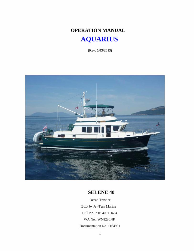
OPERATION MANUAL
AQUARIUS (Rev. 6/03/2013)
SELENE 40 Ocean Trawler
Built by Jet-Tern Marine
Hull No. XJE 40011I404
WA No.: WN8230NP
Documentation No. 1164981

2
Welcome aboard!
We are happy you have chosen Aquarius for your vacation. We are sure you will enjoy cruising the lovely islands of the Pacific Northwest.
We hope this manual will help you become familiar with Aquarius. If you have questions about the
boat or about places to visit, please do not hesitate to ask the Fleet Captain for Aquarius or the AYC staff.
PRINCIPAL DIMENSIONS L.O.A.: 45’-2” Fuel Capacity: 600 USG L.O.H.: 40’-7” Water Capacity: 180 USG L.O.D.: 40’-0” Holding Tank Capacity: 60 USG L.W.L.: 38’-5” Top Speed: 11 Kts Beam : 14’-6” Cruising Speed: 8.5 Kts
Max Draft: 4’-8” Bridge clearance mast up: 21’-2” Displacement: 41,000 lbs. Bridge clearance mast down: 13’-1”
AQUARIUIS IS A NO SMOKING VESSEL Thank you for respecting this policy.

3

4
TABLE OF CONTENTS
SAFETY EQUIPMENT 7
BOAT OPERATION
Introduction 7
Engine Inspection 8
Start Up 8
Filters 9
Things to Watch For 9
Shutdown 10
Getting Underway 10
Cruising 10
Docking 11
Fueling 11
Fuel Polishing System 12
Trolling Valve 12
BOAT ELECTRICAL
110-Volt AC System 12
Inverter Power 13
Generator 13
House (12 Volt) System 13
House Battery Bank and Switch 14
SANITATION SYSTEMS
Marine Toilet 14

5
Holding Tank 15
INSTRUCTIONS FOR USING PUMP OUT ADAPTORS 16
Y-Valve 17
WATER SYSTEM
Fresh Water Tanks 17
Fresh Water Pressure Pump 17
Hot Water Tank 18
Shower 18
Fresh and Salt Water External Faucets 18
Water Maker 18
GALLEY
Stove/Oven 18
Refrigerator 19
Salon Table 19
Freezer 19
Microwave/Toaster 19
Coffee Pot 19
Cards, Games & Puzzles 19
Storage 19
Cooking Crabs 20
HEATING SYSTEM 20
ELECTRONICS
VHF Radio 20

6
Depth Sounder 20
Radar 21
Global Positioning System 21
Loud Hailer 21
Laptop Connection 21
ENTERTAINMENT SYSTEMS
Sirius XM Radio & CD Player 21
TV/DVD 21
Sony AM/FM/CD Player 22
ANCHORING 22
Mooring Cans 23
BARBECUE 23
DINGHY AND OUTBOARD MOTOR 23
CRABBING AND FISHING 24
OTHER: BILGE PUMPS, TOOLS & SPARES, REGISTRATION,
DOCUMENTATION, AND FCC RADIO LICENSE 25
CRUISING GUIDES 26
AQUARIUS CHARTS 27
BOOK 1 MANUALS 28
BOOK 2 MANUALS 28
OTHER MANUALS 29
7
SAFETY EQUIPMENT Safety should be paramount in your daily cruising. A MAN OVERBOARD DRILL should be discussed and perhaps even practiced. Take time to inspect the life jacket sand adjust the fit for each member of your party. Always wear life preservers in the dingy and make sure that young children always wear a life jacket when out of the cabin. The dingy operator should wear on his wrist the red lanyard that is connected to the automatic engine shut off. Remember to take the portable VHF radio with you.
LIFE PRESERVERS are located in the white dock box on the boat deck. There are 8 Type II, 1 each youth and child life jackets, 2 suspender type and 2 belt type.
LIFE SLING is suspended on the rear railing of the fly bridge
FLARES are located in the starboard cupboard in the stairway to the aft stateroom
EMERGENCY SPOTIGHT is located in the starboard cupboard in the stairway to the aft stateroom
FIRST AID KIT is located in the starboard cupboard in the stairway to the aft stateroom
WOODEN THROUGH HULL PLUGS are located in the starboard cupboard in the stairway to the aft stateroom
FIRE EXTINGUISHERS are located in multiple locations: under salon table, in the aft cabin hanging locker, in the forward cabin hanging lock and two in the engine room. One of the engine room extinguishers is automatic. To manually activate, pull the pin and knob located below the aft seat in the salon.
AIR HORNS are located in the dinghy bag and in the cubby on starboard side of aft stairway
PORTABLE WATERPROOF VHF RADIO is located in its dock on starboard side of aft stateroom
BOAT OPERATION
Introduction Please familiarize yourself with the instruction manuals for all the equipment on the boat. All manuals are stored in the roll out locker beneath the lower helm seat. Most of the manuals are in two three ring binders on the lower shelf. An index to these manuals is located in a blue folder at the top of the roll out locker and also at the end of this Manual. Larger manuals, i.e., engine, transmission, waterrmaker, electronic navigation equipment, etc., are stored separately in the top shelf of the roll out locker.
Paper navigation charts covering the San Juan Islands, Puget Sound and British Columbia are stored in the forward cabin in the racks above the beds and are in numerical order. After using a chart please replace it in the correct order in the rack. A list of these charts is in front of the filed charts and also at the end of this manual. Please review this list prior to departure to ensure that your intended cruising area is covered. In addition, a waterproof chart of the San Juan Islands (number 43 which includes a number of the most popular charts for the area) is stored in the ceiling rail in the salon. Alaskan charts are located in the cupboard on the port side of the master berth. There is a parallel ruler navigation kit in the drawer under the helm seat and a second on in the cupboard on the port side of the master berth with the Alaska Charts.

8
The boat’s USCG Documentation and Washington Registration papers are in the pull out drawer beneath the microwave.
Engine Inspection Remember your “WOBBS” every morning: Water (Coolant), Oil, Bilges (Inspect and Pump-out), Belts and Sea Strainer.
• Check the level of COOLANT in the expansion tank located above the forward part of the engine. Fill to Cool Level Mark on expansion tank if necessary. Coolant must be 50/50 mix (coolant & water). Coolant is stored in the engine room in the cubby opposite the door.
• Check the level of OIL in the engine by checking the dipstick located on the port side of the engine. Check the transmission oil using the white dipstick behind the transmission front housing. Look at the etch marks on each dipstick that indicate the proper oil level.
• DO NOT OVERFILL OIL!
Only fill if oil levels are below the ½ way mark. Please use a paper towel or oil rag, not the dishtowels! Note the engine and the generator take Delo 400 15-40 wt and the transmission takes Delo 400 30 wt. Extra oil is stored in the lazzarette. DO NOT USE MULTI-VISCOSITY OIL THE TRANSMISSION OR 30 WIEGHT IN THE ENGINE OR THE GENERATOR.
• Inspect all bilges and pump-out if necessary
• Check the general condition of the BELTS, HOSES, and FUEL LINES.
• Ensure the valve on each RAW WATER THRU-HULL is in the ‘open’ position (lever in- line with valve). Periodically check the raw water strainers: close the seacock, open the strainer cover, clean the strainer, and reassemble. Remember to reopen the seacock. Check your generator fluids as well.
Start-Up
• Before starting the engine, do your inspection. The engine should be started from the lower helm station. A full set of engine alarm indicators is located above the lower helm and on the flybridge panel.
• Ensure GEARSHIFT is in ‘neutral’. BE ADVISED THAT THE ENGINE WILL START IN FORWARD OR REVERSE GEAR. PLEASE AVOID DOING THIS AS IT IS HARMFUL TO THE ENGINE!! THROTTLE should be run up and down and then brought almost back to the idle position. Insert the key into the IGNITION SWITCH.
• Turn the key fully CLOCKWISE and the ENGINE DIAL PANEL above the helm will activate. Press the BLACK STARTBUTON and release when you hear the engine start.

9
• A prolonged engine warm-up is not necessary. Even when the engine is cold, a period 0f 2-3 minutes at 1200 RPM before engaging the engine is adequate. You can stow lines and cords during this time.
• Observe the readings of the engine gauges. At normal operating RPM, the oil pressure will register approximately 40-50 PSI. The engine temperature should rise slowly. Normal operating temperature is approximately 175 degrees Fahrenheit. At idle, engine should register ~700 RPM.
Filters
1) John Deere Main Engine Oil- RE541420
Racor Fuel – 900 2 micron
Water separator – RE 515368 30 mic
Water separator – RE62425 150 mic
2) Generator Oil – Lugger/N.L. 24-08001
Fuel – Racor 2010 10 micron
Fuel (on engine) – 24-52020
3) Espar Heater
Racor R12-T
Things to Watch: for • If the engine cranks slowly or fails to turn over, check the condition of the start battery using
the voltmeter on the engine-monitoring panel above the lower helm (the engine ignition switch must be in the ON position). If the engine fails to start and the battery voltage is low, move the toggle switch on the Xantrex Pathfinder battery combiner (located to the left of the auto pilot) to manual. With the manual light on, the Pathfinder combines battery banks so you can start the engine from the house bank if the starting battery goes south. You can also run the generator to charge the batteries.
Note: It is unlikely that you will experience problems with the Aquarius batteries if you
are reasonably conservative with your power consumption. All Aquarius batteries are new (2010) Lifeline AGM sealed batteries.
10
• If the oil pressure is low, shut the engine down and inspect engine compartment looking for possible cause (e.g., loss of oil).
• If the engine is overheating or there is a lack of raw water expelled in the engine exhaust, stop the engine immediately. Recheck the raw water-cooling system to ensure the seacock is OPEN (handle in-line with valve). Next, check the raw water strainer for debris. Close the seacock, remove the strainer, clean, re-assemble, and reopen the seacock. Restart the engine and recheck water flow from the exhaust. If water is not flowing properly, the raw water pump may need to be serviced. Seek help. There is an audible alarm that will sound if inadequate raw water is flowing. Normal engine coolant operating temperature is 180 – 202 F.
Shift only when in idle!
Shut-Down Before shutting down, allow the engine to ‘idle’ for about 5 minutes to cool it gradually and uniformly. The time engaged in preparing to dock the boat is usually sufficient. Ensure the GEARSHIFT is in the ‘neutral’ position and the THROTTLE is in the ‘idle’ position. Turn off engine by pressing the RED OFF BUTTON at either helm until you hear the engine stop. Turn key fully COUNTERCLOCKWISE to the off position and remove key.
Getting Underway
DISCONNECT the shore power cord. Close the PORTHOLES and WINDOWS tightly, and lower and secure the FORWARD HATCH. Turn on your VHF and electronics. Test the BOW THRUSTER switch to make sure it is working. ASSIGN crew members their various positions. Once outside the marina, idle the engines while the crew brings in fenders and lines.
Cruising
All close quarters maneuvering should always take place at the flybridge helm for maximum visibility around boat.
Engage the GEARSHIFT. Ensure the THROTTLE is in the ‘idle’ position before engaging the gearshift to avoid transmission damage. We ask you not to run the engine at more than 1900 RPM. The best compromise between cruising speed and fuel economy is between 1400-1800 RPM. At 1800 RPM we have achieved a comfortable cruising speed of 8 knots using 4.0 gallons of diesel per hour. Higher RPMs will marginally increase cruise speed with a significantly higher fuel burn rate. Your speed will vary depending upon the weight and load, weather conditions and, especially, current.
Note—Avoid higher engine speeds as it causes higher engine temperature, possible damage, and higher fuel consumption

11
Check Engine Room every two hours. Check the engine room every two hours or so to ensure that everything is working and nothing is amiss.
Docking (you can never go too slow in a marina or when docking) During docking, use the FLYBRIDGE HELM for greater visibility to the stern. Have your crew make ready the lines and fenders and give clear instructions on how you will be docking. Occasionally during s starboard side docking your crew will need to step off from the swim step with the stern line. Another crewmember will need to be at the bow or mid-ships to hand over the next lines.
Aquarius is equipped with a BOW THRUSTER that can be a tremendous aid to docking and close quarter maneuvering. Make sure the Thruster breaker on the electrical panel is on. To ACTIVATE thruster both ON BUTTONS must be pressed simultaneously at either helm. A light will indicate that they are activated. If not used, the thruster will deactivate after a couple of minutes and must be REACTIVATED by pressing the ON buttons. The bow will move in the direction the joystick is toggled.
The Bow Thruster draws huge currents and generates significant heat. An internal thermal cutoff switch prevents the motor from burning out but you should avoid ever getting near that point. Use the thruster in short bursts of a few seconds with longer off periods in between. Primary control comes from the transmission, throttle and rudder. The thruster is not a substitute for the use of these tools.
Fueling Up Aquarius is equipped with two 300 gallon fuel tanks located port and starboard amidships. The fuel cap for the port tank is located forward of the port salon door; the fuel cap for the starboard is located astern of the starboard helm door.
The engine operates on MARINE DIESEL. CHECK and RECHECK that the correct fluid is going into the correct tank.
Before pumping, have an oil/fuel sorbs handy to soak up spilled fuel. You should have a rough idea of the number of gallons you will need by the viewing the tank monitor behind the lower helm wheel and/or the fuel sight gauges in the engine room. The tank monitor is on the starboard side of the lower helm to the left of the throttle. It monitors both water and fuel. The tank monitor is set up to monitor each fuel tank (port or starboard) but the tanks are linked so the level shown should be the same regardless. To monitor fuel, turn the right hand dial to 3.5 or 4.5. There are also 2 fuel site tubes in the engine room. (To check the water level, dial 5.5. A full water tank will show as ½ on the gauge.)
Place the DIESEL nozzle into the tank opening, pump slowly and evenly, and note the sound of the fuel flow. Pumping too fast may not allow enough time for air to escape, which may result in spouting from the tank opening. As the tank fills, the sound will rise in pitch or gurgle. Pay attention to the TANK
12
OVERFLOW VENT on the outside of the hull near the tank opening. The sound may indicate that the tank is nearly full. Top off carefully, and be prepared to catch spilled fuel. Spillage may result in a nasty fine from law enforcement.
Replace each tank cap; do not over tighten. Turn on blower before starting engines.
Caution—Clean up splatter and spillage immediately for environmental and health reasons. Wash hands with soap and water thoroughly.
Fuel Polishing System There is an ESI fuel polishing system in the engine room. After adding fuel, run the fuel polisher. Turn on switch at DC panel. Set timer at fuel polisher in Engine Room. You must be on the generator or, preferably, shore power. Polish one tank of fuel at a time by adjusting the Parker Ball Valves above the unit so that fuel is only coming from one tank at a time. Turn the timer to 2 hours. When done, repeat the process with the other tank. The system will turn off automatically when finished. Turn off switch at DC panel. This is desirable but not mandatory unless you feel you’ve picked up some dirty fuel.
Trolling Valve Aquarius is equipped with a trolling valve located at the lower helm to the right of the wheel. It is a “pull out” type. It should not be necessary to use this valve unless you are trolling for salmon.
To activate the valve, slow the boat to idle, put the gearshift in neutral, and gently pull out the valve. The further the valve is extended, the slower the speed. DO NOT EXCEED 1100 RPM WHILE THE TROLLING VALVE IS EXTENDED. Serious damage to the transmission could occur.
BOAT ELECTRICAL The electrical system is divided into two distribution systems: 110-volt AC and 12-volt DC.
The systems are controlled from the AC ELECTRICAL PANEL, the DC ELECTRICAL PANEL, and the BATTERY SWITCHES which are all found in the GLASS DOOR CABINET on the side of the lower helm.
A Wiring and Plumbing System Schematics is located in the pull out drawer under the microwave.
AC power is delivered by shore power, the generator or the inverter. DC power comes either from the batteries or the AC system via the chargers. A Xantrex remote inverter monitoring panel located at the lower helm provides additional information on the electrical status of the boat. Monitor the use of onboard electricity carefully and turn off electrical devices that are not needed. Electrical breakers have been accurately labeled. The Red light indicates that they are on.
110-Volt AC System
SHORE POWER supports all AC equipment and receptacles on board, as well as the battery chargers.
There are two 50’ 30A shore power cords aboard – one in the long locker in the cockpit and one in the middle seat locker, port side flybridge.
13
To connect to shore power, plug the 30 amp cord into the dock receptacle. Check the power rating/plug size of the nearest dock receptacle (that is 30 amps, 20 amps, or 15 amps). If necessary, add a CORD ADAPTER located in the small outside fold down locker forward of the freezer. Turn the dock power on. At the ELECTRICAL PANEL, flip the SHORE CIRCUIT BREAKER on. Check for reverse polarity. Then turn on appropriate breakers for battery charger, refrigeration, water heater, and microwave, etc. Watch your volt meter for load. If the load exceeds voltage, you will pop your breaker. If this occurs, wait to turn on one of your systems (i.e. water heater) until your use of volts drop.
If your outlets fail to work, check your GFIs to make sure that they have not been tripped.
When disconnecting from shore power, turn off the dock receptacle before disengaging the power cord. Leave the power cord connected to the boat at 30 Amp receptacles.
Inverter Power The INVERTER provides AC power to the 110-volt receptacle plugs (i.e. the microwave oven) when the boat is disconnected from shore power. The inverter does not provide power to the water heater or the battery charger. Your inverter panel is located at the helm station with an on/off switch. Make certain that it is on. The actual inverter is located in the engine room.
The inverter’s power source is the DC house or inverter batteries located in the engine room. The quantity of DC power is limited to the capacity of these batteries. Therefore, running hair dryers, toaster, coffeepots, space heater, etc. and will quickly discharge the house/inverter batteries. It is best if you need to run the big appliance that you turn on the generator.
When connected to shore power, the inverter automatically becomes a battery charger for the 12-volt HOUSE BATTERIES. Should you detect the inverter failing to charge the house batteries, check the circuit breaker in the AC Panel. And the inverter control panel. Also, there is a circuit breaker located on top of the inverter box.
Generator To start the GENERATOR, first check that your generator’s fluids are topped off and the raw water intake is open. The generator controls are located at the lower helm. First pre-heat the generator by pushing the top switch down for about 20 seconds. Then while still pre-heating lift the start switch. Hold both switches in that position while the generator catches (about 5-10 seconds). Make sure water and exhaust is exiting the port side stern.
After generator is running, change your AC distribution switch to generator. Then turn on AC systems as you would on shore power one system at a time.
To turn the generator off, first take off the load by turning off AC breakers. Then turn off main AC distribution switch. Let the generator run without a load for about 2-3 minutes to cool down. Lastly kill the generator by switching generator switch to “off” until it dies.
House (12-volt) System

14
Four battery banks support 12-volt DC power: 1) Main engine battery (1 8D); 2) Generator start battery (1 4D); 3 ) house battery bank (2 8D); and 4) Bow thruster (1 8D).
Your 12 volt panel shows all the systems supported by your batteries. Primarily you will be turning on the breakers for your lights, water pressure, electronics, etc. The one exception is the DC switch for the Fresh Water Wash Down. This switch is located at the lower right of the AC panel. Bilge pumps should always be left on (Auto) and are on a separate panel under the main 12 volt panel.
House Battery Bank & Switch The HOUSE BATTERY BANK provides power for all DC systems, except the engines and automatic bilge pumps. When disconnected from shore power, all 12-volt devices drain the house battery. Use devices as needed.
The Xantrex PathMaker is a battery combiner that automatically connects 2 or three battery banks for simultaneously charging and isolates them during discharge.
When a battery bank is being charged, the voltage will read from about 13.1 volts to 14.4 volts depending upon state-of-charge of the battery bank. When the battery bank is at rest, (that is, not being charged), the voltmeter can give a rough indication of the state-of-charge of the battery bank.
All batteries are charged by the engine ALTERNATOR while underway. The engine/house batteries are charged by the BATTERY CHARGER when connected to shore power. Ensure the Battery Charger and Inverter circuit breakers at the electrical panel are ON. The GENERATOR will also charge the batteries as long as the Battery charger and inverter breakers are on.
Battery turn off switches are locate below and to the right of the lower wheel behind a teak and glass door.
SANITATION SYSTEM
Marine Toilet The sanitation HOLDING TANK holds 60 gallons. There is a Tank Watch warning panel located below the engine controls at the lower helm on the right but do not rely solely on it. Sixty to eighty flushes means you’re getting close to needing a pump-out.
The vessel is equipped with two fresh water electric marine Tecma toilets. Each toilet has an adjacent control panel with two buttons. The button on the left is labeled “BEFORE USE”; the button on the right is labeled “AFTER USE”. To conserve water, the following procedures are highly recommended. For urination, simply use the toilet and then press the “AFTER USE” button. For solid human waste, first press the “BEFORE USE” button to pre-fill the bowl. When you are done, press the “AFTER USE” button. A few seconds after the flush a macerator pump will move the effluent to the holding tank.

15
To recap:
• For #1, “AFTER USE” button ONLY.
• For #2, “BEFORE USE” button first; “AFTER USE” button when mission accomplished.
It is important that every member of the crew be informed on the proper use of the MARINE TOILET. The valves, openings, and pumps are small and may clog easily. If the toilet clogs, it is YOUR RESONSIBILITY!
Always pump the head for children, so you can make sure nothing foreign is being flushed.
Caution – Never put paper towels, tampons, Kleenex, sanitary napkins, household toilet paper, or food into the marine toilet. Use only the special dissolving marine toilet tissue provided by AYC.
The TOILET THRU-HULL is located under the forward cabin’s sole. The valves are set up so that the toilets discharge ONLY INTO THE HOLDING TANK. Do not change any of the Y-valves.
Holding Tank The sanitation HOLDING TANK holds approximately 60 gallons. Be aware of the rate of waste production (about 1 gallon per flush). With an overfilled tank, it is possible to break a hose, clog a vent, or burst the tank. The result will be indescribable catastrophe and an EXPENSIVE FIX to you. Empty the tank EVERY OTHER DAY to avoid this problem. Please check on the local regulations for where discharging is allowed (this is your responsibility). No discharge is allowed in US waters and only in certain areas in Canada. Manage the holding tank capacity by using shore facilities whenever possible and by monitoring the level of the tank.
The HOLDING TANK is located under the sole in the forward stateroom. There is a Tank Watch holding tank indicator with four indicator lights (“Empty”, “Low”, “Mid”, and “Full”) located at the main lower helm station, but do not rely totally upon these as they often get clogged. When the “Mid” indicator light comes on, you should pump out as soon as possible. You should never see the “Full” indicator light! If you do, the tank is truly full. Do NOT flush even once.
The holding tank is emptied in one of two ways:
#1 At the Marine Pump-Out Station, remove the WASTE CAP located Starboard side, forward of sliding door. Insert the pump-out nozzle into the waste opening. Double-check your deck fitting! You may need an ADAPTER for some pump out setups. There are two ADAPTERS and a screw on extension in a clear plastic box located in the engine room by the large toolbox. READ THE “INSTRUCTIONS FOR USING PUMP OUT ADAPTERS” below and located in the box with the adapters. Turn on pump and open valve located on handle. When pumping is finished, close lever on handle and turn off pump. Remove from deck fitting.
Thoroughly clean, dry and restore adapter(s).
16
If there is a fresh water hose on the dock, rinse the tank by adding 2 minutes of water into tank. Then re-pump to leave the tank rinsed for the next charter. This also eliminates head odors.
NOTE: THE PUMP OUT NOZZLE IN SOME MARINAS MAY NOT BE COMPATIBLE WITH THE SELENE PUMP OUT FITTING (e.g., ROCHE HARBOR FUEL AND PUMP OUT DOCK). THEREFORE, IT IS ADVISIBLE TO PUMP OUT THE HOLDING TANK WHENEVER YOU ARE AT A MARINA WITH A PUMP OUT NOZZLE THAT FITS, IRRESPECTIVE OF THE TANK LEVEL.
IF ALL ELSE FAILS YOU CAN CONTACT PUMPMEOUT.COM, A MOBILE PUMP OUT SESRVICE SERVING AROUND SEATTLE, PUGET SOUND AND THE SAN JUANS. 877-766-7631 OR 425-903-3137.
#2 The tank’s contents can be discharged with the MACERATOR only in Canadian waters and only in approved discharge zones.
To operate the macerator, turn on the Macerator breaker (bottom left breaker on DC panel). Listen to the macerator’s sound. When the pitch becomes higher, the tank is empty. Discharge may be observed on the starboard side. It should only take a few minutes to empty the tank. Be careful to not run the pump dry as it will burn out .
There is a spare macerator stored in the top step leading to the aft cabin.
INSTRUCTIONS FOR USING PUMP OUT ADAPTORS Various marinas will have different types of pump out nozzles on the pump out hose. As an example, there are tapered rubber nozzles, cam-operated couplings, or rubber flange. While some may work on a Selene without an adaptor (i.e., tapered rubber nozzle) many will not, specifically the rubber flange type found at the Roche Harbor pump out dock.
We have provided adaptors that will, hopefully, accommodate all nozzles you may find on your trip. When getting ready to pump out, proceed as follows:
1. Unscrew the WASTE cap on the starboard side of the boat, forward of the sliding door.
2. Determine the type of nozzle on the pump out hose. If it is the tapered rubber type, it may fit without an adaptor (Remember YOU NEED a GOOD TIGHT SEAL for the vacuum to work.
3. If the nozzle won’t work, screw the NozAll adaptor (labeled “Adaptor #1) into the deck fitting. Insert pump out nozzle into NozAll adaptor and begin pumping.

17
4. If the marina has a flange type pump out nozzle, or the NozAll adapter itself won’t work, screw the NozAll adaptor into the fitting, and fit the rubber end of Adaptor #2 over the NozAll adaptor and push the rubber end down until there is a tight, secure fit. It may be necessary to coat the top of the NozAll adaptor with a small amount of lubricant to get it to fit. There is a screw on extension for Adaptor # 2 that may b e required. Insert the pump out station nozzle over the white PVC, holding it down to secure a tight seal, and begin pumping. There is also a third adaptor, consisting of a 1 ½” hose barb, plastic pipe and standard deck fitting. Screw in Hose barb to deck fitting, place plastic hose over barb, tighten hose clamps.
5. If none of these adaptors work, talk to marina staff to see if they can change or modify their nozzle.
6. When finished, screw in deck fitting, disengage Adaptor #2, unscrew Adaptor #1, WASH AND DRY THEM BOTH THOROUGHLY, and then store in plastic box.
IF ALL ELSE FAILS YOU CAN CALL PUMPMEOUT.COM, A MOBILE PUMP OUT SERVICE, AT 877-786-7631 OR 425-903-3137. THEY SERVE AROUND SEATTLE, PUGET SOUND AND THE SAN JUANS. SEE REVERSE SIDE FOR INFO.
Y-Valves
The Y-VALVES direct waste effluent into the sanitation-holding tank or flushes the effluent ‘directly overboard’. There are two Y-Valves; one in each head. They are set to direct effluent to the holding tank. Y-valves are usually wire-tied to the holding tank position in respect to Coast Guard regulations. Please leave it “as is” unless there is an emergency. Be familiar with the applicable laws concerning dumping sewage directly overboard.
WATER SYSTEM
Fresh Water Tank(s) The FRESH WATER TANK holds 180 gallons. Observe the water level by checking monitor at lower helm station (DIAL TO NUMBER 5.5). When the gauge reads slightly over ½ full, the water tank is full. (Be sure that the “nautical instrument breaker is on). Waste water from the sinks and showers drains overboard through various thru-hulls usually located under the sinks.
To refill the tank, remove the WATER cap located Starboard side aft in the cockpit area. Avoid flushing debris from the deck into the tank opening. DO NOT fill water and diesel at the same time!
There is a portable carbon filter located in the stern deck locker. If you wish to filter dock water when filling the boat water tank, attach the filter between 2 hoses.
18
Fresh Water Pressure Pump The pump is activated at the DC panel by turning on the breaker. If the water pump continues to run, you are either out of water or might have an air lock and need to bleed the system by opening up a faucet. If you run out of water SHUT OFF YOUR HOT WATER HEATER on the AC panel. Serious damage can occur! The pump is located beneath the forward edge of the master bed.
Hot Water Tank The HOT WATER HEATER has a 12 gallon capacity tank and is available when connected to shore power or via a heat exchanger when underway. To use on shore power, flip on the water heater circuit breaker on the AC electrical panel. Do not use the water heater if the water tank level is very low. The water heater is located in the engine room port side.
Shower
Before taking a SHOWER, make sure the fresh water pressure breaker is on. Take only very short “boat” showers (turning off water between soaping up and rinsing). To keep shower tidy wipe down the shower stall and floor. Check for accumulation of hair in the shower and sink drains. Ensure that the faucets and nozzle are completely off after use.
Fresh and Salt Water External Faucets There is a fresh water faucet located in the port anchor locker. Use this faucet to wash down windows and anchor. There is a saltwater faucet and a fresh water faucet located in the long storage locker in the cockpit. The DC breaker for the fresh water wash down pump is located at the bottom right of the AC breaker panel. Use the fresh water faucets sparingly and always make sure the faucets are completely closed. The pumps for these faucets are in the engine room outboard of the water heater.
Water Maker There is a 15 gph water maker in the engine room. It is currently in the “pickled” condition, i.e., not available for making water. If you plan to be cruising for an extended period of time where you will not have readily available marina water, please ask your Anacortes Yacht Charter representative to “unpickle” the water maker, install a new filter and instruct you in the use of the water maker before you commence your trip. Extra filters are in the lazarette.
GALLEY
Stove/Oven The stove and oven are propane.
The unit is activated as follows:

19
#1 Turn open the propane tank located in the port locker on the flybridge and check the tank pressure. There are two propane tanks. Switch to the second tank if the first runs out.
#2 Turn on the solenoid pressure switch which is the left button on the Propane Control System located above the stove.
#3 Turn on the gas at the stove (Press in knob). You might need to hold knob in for a few seconds while the thermo coupler warms up. The same applies to lighting the oven.
When finished cooking turn off the left button on the Propane Control System.
Refrigerator The REFRIGERATOR is dual voltage (12-volt and 110-volt power). It will automatically use 110- volt power when the shore power is connected; otherwise, it will operate on 12-volt power. Monitor the use of the refrigerator when the engines are not charging the 12-volt battery system.
Salon Table The salon table can be extended. Have two people pull from each end and the table will separate and an insert will automatically pop up. Please use place mats and coasters when using the table. Please do not place glasses or mugs on the bare wood.
Freezer There is an 8.8 cf FREEZER mounted on the mid-deck. It is plugged into an external 110 volt source. If both the freezer and the refrigerator are run overnight when you are not on shore power, it is likely the house batteries will be low in the morning (indicated by the “yellow ” or “red” lights on the remote inverter panel located above the lower helm wheel next to the John Deere instrument panel). In this case it will be necessary to run the generator until the inverter lights return to the “green” position. Since you will likely be running the coffee maker and/or the microwave/toaster in the morning, you should run the generator if you are not on shore power. In order to conserve battery power, you can turn the freezer off overnight by either unplugging it or turning off 110 volt the breaker labeled flybridge outlets (FB Outlets)
Microwave Toaster Combination
The microwave /toaster is by the port door. The instructions are in the drawer beneath the unit. Coffee Pot The Aquarius is equipped with an electric coffee maker. If this should fail, there is a backup melita coffee cone and filters under the top step of the aft stairway. Cards, Games & Puzzles There are some playing cards, games and picture puzzles in the cupboard on the starboard aft wall of the salon. Storage

20
In addition to three cupboards above the galley counter and the cupboard on the starboard aft wall of the salon, additional less obvious storage options are:
1) Under the bowl behind the settee, salon aft 2) Under the first and third step going into the forward cabin 3) Under the third step going into aft cabin 4) Under the helm seat (excellent for wine bottles) 5) Under the settee behind the helm seat. This is inconvenient but very large.
Cooking Crabs There is a large pot for cooking crabs that is located under the fly bridge. Please do not cook crabs in the cabin. Use the BBQ on the stern. It is important to lock the galley drawers. They open very easily and will do so if the boat rolls.
HEATING SYSTEM The ESPAR DIESEL FORCED-AIR FURNACE located in the engine room provides heat in the same way as a household furnace. The thermostat and on-off switches are located in the salon area, next to the slide out locker under the front helm seat.
Check The furnace EXHAUST PORT located port side below door for any obstruction such as fenders or lines. Do not block this opening when operating the furnace. Heat will damage fiberglass or rubber. Once it is on, allow it to run for at least 15 minutes before turning it off. Turn ‘off’ the furnace heater by turning switch back off.
ELECTRONICS All electronics manuals are located in the slide out locker under the lower helm seat. “Quick Reference” cards are in the insert at the end of the “Boat Copy” of the Aquarius Operating Manual. The Raymarine chartplotter is loaded with two C-Map chart chips that should cover Puget Sound, the Gulf Islands and most of British Columbia. Additional chart chips (Victoria to Cape St. James and Southeast Alaska) are located at the top front of the slide out locker beneath the lower helm seat.
The chartplotter on the flybridge is the master for the radar, i.e., turn it on first, and then turn on the lower helm chartplotter and GPS.
VHF Radio There are 3 VHF RADIOS. The first is located at the main helm, below the GPS, and the second on the flybridge. Make sure the VHF breaker is on located at the 12 volt panel. Always monitor channel 16 while underway. The VHF radio call sign is WDC 4095. The third VHF radio is a portable handheld waterproof model for use in the dingy. It is stored in its charging dock in the Master Stateroom.
21
Depth Sounder Each chartplotter also acts a depth sounder. Additionally, there is a back up Raymarine depth sounder at the flybridge just forward of the instrument panel and on the lower helm below the radio. When under way it is a good idea to set your shallow depth alarm to 20’ so an alarm will go off if you unexpectantly encounter water less than 20’.
Remember to ALWAYS consult your charts for depth!
Radar The radar must be turned on at the upper (master) Raymarine chart plotter at the flybridge. The radar can be run in full screen or split screen mode on both the upper and lower displays.
Global Positioning System (GPS) A fixed mount GPS is located at the lower helm station. This is connected to the Raymarine chart plotters and must be turned on to run the navigation systems.
Note: GPS is considered a navigation aid. Do not rely on it. Compasses, charts and dividers are the tools to plot position, course and speed.
Loud Hailer
There is a dedicated loud hailer located at the lower helm on the overhead panel. This can be used as a loudspeaker or for automatic foghorn signals. This is especially useful when travelling in fog.
Lap Top Connection
There is a power outlet located above the chart table and a connector cable to GPS stored in the box on the chart table. This enables you to run a navigation program on your laptop.
ENTERTAINMENT SYSTEMS
Sirius XM Radio & CD player
The Jensen Sirius XM radio is located just above the chart table at the lower helm. It will accommodate an iPod through Aux In. There is a remote control mounted next to the ESPAR thermostat. There are 4 external speakers.
TV/DVD A TV is stored in the entertainment cabinet under the chart table. To lower the panel, use the releases on the each side of the panel. The DVD player is behind the left side of the TV along with the DVD

22
remote. The TV remote is on the right side of the TV. Make sure the TV/VCR AC breaker is turned on. Turn on the TV and VCR using the remotes and set the TV to channel 3. This TV can only be used for playing DVDs.
Sony AM/FM/CD Player This radio is on the bridge instrument console. It has 2 remote speakers. There are a number of CDs located in the storage shelf above the dish cabinet in the salon.
ANCHORING The primary WORKING ANCHOR is a 55 lb Delta and is attached to 300 ft chain passed through the deck from the starboard ANCHOR LOCKER. The locker can be accessed through the foredeck. There is an anchor keeper. Release it first and then you can lower the anchor from any of the three stations. We would prefer that you raise the anchor from the foredeck to keep an eye on it when it breaks water so that it does not swing back into the boat’s bow.
The WINDLASS POWER SWITCH is located at the lower helm station to the right and below the wheel.
There is an Electronic Windlass Controller and Counter for chain rodes (Auto Anchor 500C) at both stations. This can be used to lower or raise the anchor. (The digital display of the number of feet of rode out is currently not working.) Additionally, there is a switch at both stations that can be used to lower or raise the anchor. Finally, there are 2 foot controls beneath the windlass.
At the bow, tap gently on the ‘down’ foot control to lower the anchor. If necessary, guide the anchor over the anchor roller to prevent binding on the pulpit.
Let out sufficient ANCHOR RODE before setting the anchor. Colored markers (cable ties) are placed at 100 feet and every 20 feet thereafter on the chain, indicating amount of rode. (The digital readout is not working). Put down at least a 4 to 1 scope (80 feet for 20 feet of water); back the anchor in with a short burst from the engine. Then let out additional scope dependent upon conditions.
There is a spring line in the port anchor locker. If you wish to use it, after you have set the anchor, hook the stainless “S” clip to the chain and let out about 20’ additional feet of chain, securing the end of the spring line to the Sampson post. The chain should be slack and the tension is transferred to the spring line. Make sure that the anchor roller lock is engaged.
Before raising the anchor, ALWAYS start the engine as it uses large amounts of power. Turn ‘on’ the WINDLASS SWITCH and as the boat moves toward the anchor, press the ‘up’ control to take up slack line. Give the windlass short rests as you are pulling it up. Place yourself in position to guide the anchor onto the roller. As the anchor rises, be careful not to allow it to swing against the hull.
Using the hose and fresh water faucet in the port anchor locker, wash down the anchor and chain if they are coming in muddy.
Reconnect the keeper between the windlass and chain. Close the plastic covers on the FOOT PEDAL CONTROLS. Turn “off” the WINDLASS POWER SWITCH.

23
A spare Fortress anchor and 200 feet of 5/8” nylon line are stowed in the port anchor locker. Attach the rode securely to the chain shackle.
Mooring Cans The State Park Sticker on your vessel allows you to pick up the MOORING CANS in the parks for free. You only need to register at the kiosk usually located at the heads of the docks. Mooring cans have a metal triangle at the top upon which is a metal ring. The metal ring is attached to the chain that secures your boat. IT IS VERY HEAVY. The strongest member of your crew should be picked for this job.
Come up to the CAN into the wind as you would for anchoring. Have crew members on the bow, one with a boat hook and one with a mooring line secured like a bow line. As you are coming slowly into the can have the crew holding the boat hook point at the can with the hook so the skipper always knows where it is. Hook the can and bring the ring up to the boat to allow the second crew to thread the ring with the line. Release the hold with the boat hook. If your mooring line is led out the starboard chock bring the end of the line back through the port side. You will essentially create a bridle with about 10 feet of slack from the chalk to the can.
BARBECUE The barbecue is mounted on the aft rail. Attach a PROPANE BOTTLE to the REGULATOR. Carefully light the unit, preferably with a long-stem butane lighter. The barbecue generates a lot of heat and cooks hot and fast. Please clean grill with a wire BBQ brush.
Note: Propane bottles are not stocked by AYC. You will need to purchase one if extras are not found on board. Caution—For safety reasons, do not store an opened propane bottle within the salon or engine compartment. Chances are these will leak slightly once opened and propane gas could settle into low spaces. Store these bottles in the cabinet on the port side of flybridge. Ensure gasoline and flammable materials are not near the barbecue.
DINGHY & OUTBOARD MOTOR The 11 ft Brig dinghy with a 15 hp Honda engine is mounted on a Sea Wise hydraulic davit system on the swim step
The keys to the davit system and the dinghy ignition are in a teak box labeled Selene on the dash in the salon.
To deploy the dinghy, unlock and disengage the slide through latch, and remove the SS cylindrical pin (on port side of control box) the Sea Wise davit. Lower the dinghy by depressing the switch on the starboard side of the davit. The engine will automatically lower and come to rest on the SS saddle on the dinghy transom. If the engine does not rest completely on the saddle, it may be necessary to raise the engine and “jiggle” it until it comes to rest on the saddle. Tighten the right side motor bolt to the saddle. Disengage the davit and raise it to an upright position.
24
The dinghy gas container is in the lazzarette. Connect it to the engine and squeeze the in-line bulb a number of times to get gas into the engine.
Lower the engine all the way using the up-down controls on the dinghy shift lever.
Insert the dinghy key into the ignition and turn clockwise to start. On the initial start you may need to use the choke lever. Let the engine warm up for a few minutes before disengaging from the boat. Make sure you see a stream of water exiting from the rear starboard of the engine. If there is no stream of water, shut down the engine and try to clean out the exit port using a toothpick or a piece of wire. If this doesn’t work, seek professional help before trying to use the dinghy.
Once the engine is started, disengage the small lock pins at the mounting brackets, then disengage the mounting brackets (dinghy to swim step) and move slowly away from the boat.
On return, approach the boat slowly and line up the dinghy with the swim step mounting brackets. In order to engage the brackets you may have to shift some weight to the port side to lower the dinghy attaching locks enough to engage those on the swim step. Insert the locking pins.
Raise the engine sufficient to clear the dinghy tube. Lower the Sea Wise attaching cable and hook the eye over the hook on the engine. Raise the dinghy by pushing up on the switch until it engages the davit. Insert the SS cylindrical pin and the slide through locking latch. Lock the latch.
Flush the engine with fresh water using the “rabbit ears” attachment in the cockpit locker. Place the suction cups over the engine intake slots (lower end of engine shaft), turn on fresh water and start engine. Run for a few minutes, making sure there is a stream of water coming from the engine.
There is a bag stored in the lazarette which goes under the dinghy back seat and contains flares, a horn, a patch kit, extra line, a flashlight, a foot operated air pump, a grappling hook and line, and an anchor. There are also air pumps in the lazarette locker.
Be very careful. The dinghy and its davit and controls are not toys; make sure that only adults launch, operate and retrieve the dinghy.
Note: Wear a life jacket and take a portable VHF radio with you whenever using the dinghy
CRABBING AND FISHING
Always check the fishing and crabbing regulations before you leave on your cruise. You will need a license. Many areas are CLOSED to crabbing and fishing on certain months.

25
There is a crab pot, float and line in the lazzarette. There are three prawn traps under the forward port seat of the fly bridge and floats and lines in the starboard side flybridge locker. There is an Ace electric pot puller in the under the forward port seat of the fly bridge that mounts on the Scotty downrigger rail mounted pads and plugs into the corresponding outlet
There is a green fish-cleaning table in the lazarette. It fits into the pole holders on the rail.
CRAB AWAY FROM THE BOAT. Lines can get wrapped around props.
OTHER: Bilge Pumps, Tools & Spares, Ship’s Papers
Aquarius is equipped with AUTOMATIC BILGE PUMPS. The master switches are located on the electrical pane below the DC switches. Normally, the switches will be left in the AUTO position. You may occasionally hear a pump operate due to condensation and water from the shaft log accumulating in the bilge.
An AUXILIARY HAND OPERATED BILGE PUMP is operated using the handle provided for that purpose. The pump and handle are located beneath the forward cabin hanging locker. This is used only in emergency situations.
Engine spares and filters are stored in the lazarette.
Generator filters and belts are stored in front of the engine in a blue plastic box
Tools are stored in the toolbox just inside the door of the engine room on the starboard side.
Specialty items (hose clamps, filter tools, caulking, large sockets, duct tape, 3/8th socket set) are stored in the large toolbox forward of the engine.
Small spares (batteries, fuses, screws, fasteners, light bulbs, bungee cords, zip ties, twine etc.) are in the starboard cubby by the shower in the master stateroom.
Electric Drills, extension cords, trouble light, and small air compressor for the hynautic system are under the second step to the master stateroom.
Coolant (50-50 antifreeze water) is stored in the engine room in the locker above the engine fuel site tubes on the starboard side.
Engine and Generator oil (Delo 400 15-40 weight) 3 gallons are located in plastic box forward of the engine.
Transmission oil (Delo 400 30 weight) 2 quarts are located in the cupboard directly in front of you as you enter the engine room.
There is an emergency tiller located in the lazarette.
Registration, Documentation and FCC Radio License are located in the drawer beneath the microwave.

26
We hope you enjoy your trip! If there are any questions, do not hesitate to call Anacortes Yacht Charters. If you have any suggestions as to how this Operation Manual might be improved, please let AYC know.

27
CRUISING GUIDES
The owners of Aquarius have done a lot of cruising from the San Juan Islands to Alaska and in the process have collected many cruising guides. Those that apply to the southern waters are behind the helm seat and those that apply further north are in the aft cabin port side. We hope you enjoy them and that they inspire you to extend your cruising range in a future cruise.
Puget Sound and the San Juan Islands: Olympia to Port Angeles (Migael Scherer)
Gunkholing in the San Juans (Al Cummings and Jo Bailey-Cummings)
Exploring the Inside Passage to Alaska – San Juans to Glacier Bay (Don Douglass)
San Juan Islands: A Boaters Guidebook (Shawn Breeding and Heather Bansmer)
Gulf Islands & Vancouver Island From Sooke to Courtenay: Cruising Guide to British Columbia Vol. 1 (Bill Wolferstan)
Desolation Sound & Discovery Islands: Cruising Guide to British Columbia Vol. 2 (Bill Wolferstan)
Sunshine Coast – Fraser Estuary and Vancouver: Cruising Guide to British Columbia Vol. 3 (Bill Wolferstan)
Vancouver Island’s West Coast (Don Douglass)
Best Anchorages of the Inside Passage: British Columbia South Coast Gulf Islands to Cape Caution
North of Desolation Sound: The Broughton Islands (Peter Vassilopoulos)
The Broughtons and Vancouver Island: Dreamspeaker Cruising Guide Vol. 5 (Yeadon-Jones)
The Broughtons Archipelago Map
Alaska and Canada’s Inside Passage: Cruise Tour Guide
28
AQUARIUS CHARTS
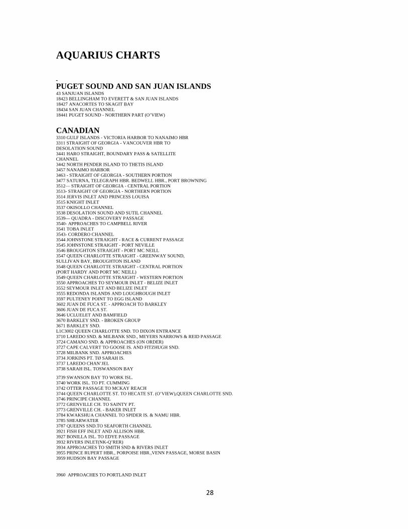
PUGET SOUND AND SAN JUAN ISLANDS 43 SANJUAN ISLANDS 18423 BELLINGHAM TO EVERETT & SAN JUAN ISLANDS 18427 ANACORTES TO SKAGIT BAY 18434 SAN JUAN CHANNEL 18441 PUGET SOUND - NORTHERN PART (O’VIEW)
CANADIAN 3310 GULF ISLANDS - VICTORIA HARBOR TO NANAIMO HBR 3311 STRAIGHT OF GEORGIA - VANCOUVER HBR TO DESOLATION SOUND 3441 HARO STRAIGHT, BOUNDARY PASS & SATELLITE CHANNEL 3442 NORTH PENDER ISLAND TO THETIS ISLAND 3457 NANAIMO HARBOR 3463 - STRAIGHT OF GEORGIA - SOUTHERN PORTION 3477 SATURNA, TELEGRAPH HBR. BEDWELL HBR., PORT BROWNING 3512— STRAIGHT OF GEORGIA - CENTRAL PORTION 3513- STRAIGHT OF GEORGIA - NORTHERN PORTION 3514 JERVIS INLET AND PRINCESS LOUISA 3515 KNIGHT INLET 3537 OKISOLLO CHANNEL 3538 DESOLATION SOUND AND SUTIL CHANNEL 3539— QUADRA - DISCOVERY PASSAGE 3540- APPROACHES TO CAMPBELL RIVER 3541 TOBA INLET 3543- CORDERO CHANNEL 3544 JOHNSTONE STRAIGHT - RACE & CURRENT PASSAGE 3545 JOHNSTONE STRAIGHT - PORT NEVILLE 3546 BROUGHTON STRAIGHT - PORT MC NEILL 3547 QUEEN CHARLOTTE STRAIGHT - GREENWAY SOUND, SULLIVAN BAY, BROUGHTON ISLAND 3548 QUEEN CHARLOTTE STRAIGHT - CENTRAL PORTION (PORT HARDY AND PORT MC NEILL) 3549 QUEEN CHARLOTTE STRAIGHT - WESTERN PORTION 3550 APPROACHES TO SEYMOUR INLET - BELIZE INLET 3552 SEYMOUR INLET AND BELIZE INLET 3555 REDONDA ISLANDS AND LOUGHROUGH INLET 3597 PULTENEY POINT TO EGG ISLAND 3602 JUAN DE FUCA ST. - APPROACH TO BARKLEY 3606 JUAN DE FUCA ST. 3646 UCLUELET AND BAMFIELD 3670 BARKLEY SND. - BROKEN GROUP 3671 BARKLEY SND. L1C3002 QUEEN CHARLOTTE SND. TO DIXON ENTRANCE 3710 LAREDO SND. & MILBANK SND., MEYERS NARROWS & REID PASSAGE 3724 CAMANO SND. & APPROACHES (ON ORDER) 3727 CAPE CALVERT TO GOOSE IS. AND FITZHUGH SND. 3728 MILBANK SND. APPROACHES 3734 JORKINS PT. TØ SARAH IS. 3737 LAREDO CHAN’JEL 3738 SARAH ISL. TOSWANSON BAY
3739 SWANSON BAY TO WORK ISL. 3740 WORK ISL. TO PT. CUMMING 3742 OTTER PASSAGE TO MCKAY REACH 3744 QUEEN CHARLOTTE ST. TO HECATE ST. (O’VIEW),QUEEN CHARLOTTE SND. 3746 PRINCIPE CHANNEL 3772 GRENVILLE CH. TO SAINTY PT. 3773 GRENVILLE CH. - BAKER INLET 3784 KWAKSHUA CHANNEL TO SPIDER IS. & NAMU HBR. 3785 SHEARWATER 3787 QUEENS SND.TO SEAFORTH CHANNEL 3921 FISH EFF INLET AND ALLISON HBR. 3927 BONILLA ISL. TO EDYE PASSAGE 3932 RIVERS INLET(NK-Q’RER) 3934 APPROACHES TO SMITH SND & RIVERS INLET 3955 PRINCE RUPERT HBR., PORPOISE HBR.,VENN PASSAGE, MORSE BASIN 3959 HUDSON BAY PASSAGE
3960 APPROACHES TO PORTLAND INLET

29
BOOK 1 MANUALS
(Book 1 and Book 2 Manuals are in 3 ring binders in the lower portion of the slide out locker beneath the helm seat. An Index to Manuals is in a blue folder at the top of this locker)
1. ICOM VHF RADIO
2. REVERSO OIL CHANGE SYSTEM
3. SIDE POWER BOW THRUSTER
4. N. LIGHTS OPS MANUAL
5. N. LIGHTS DERALER DIRECTORY
6. N. LIGHTS WARRANTY
7. N. LIGHTS PARTS CATALOG
8. N. LIGHTS INSTALLATION MANUAL
9. LOFRANS INSTALLATION MANUAL
10. FORCE 10 STOVE
11. HYNAUTICS STEERING SYSTEM
12. RACOR FUEL FILTER
13. TUNDRA REFRIGERATOR
14. L. P. GAS SYSTEM
15. RARITAN WATER HEATER
16. FLOJET WATER SYSTEM
17. RITCHIE COMPASS
18. ESI FUEL MANAGEMENT SYSTEM
19. FORCE 10 BARBECUE
20. HONDA OUTBOARD
BOOK 2 MANUALS
1. AUTO ANCHOR
2. RAYMARINE AUTO PILOT

30
3. SIRIUS RADIO TUNER AND GALAXY ANTENNA
4. JENSEN/SIRIUS XM RADIO
5. SCOTTY DOWNRIGGER
6. RAYMARINE HYDRAULIC PUMP
7. SONY RADIO/STEREO
8. STANDARD HORIZON LOUD HAILER
9. XANTREX INVERTER
10. TWIN DISC OPS MANUAL
11. SHAKESPEARE VHF ANTENNA
12. GUEST SPOTLIGHT
13. CEASE FIRE EXTINGUISHER REMOTE CONTROL
14. CEASE FIRE EXTINGUISHER SYSTEM
15. ESPAR HEATER
16. SEA WISE DAVIT
17. TV INSTALLATION PANEL
18. TIGRESS WINDLASS
19. TECMA TOILET
20. ACE LINE HAULER
21. RAYMARINE FISH FINDER
22. SUSPENDER PFD
23. DINGHY DSEPTHSOUNDER
24. WATER MAKER MANUAL (IN DRAWER)
25. JABSCO FRESH WATER WASH DOWN PUMP[
26. FIRST ALERT CO ALARM
OTHER MANUALS
The following manuals are located in the top of the slide out locker beneath the helm seat:
1. Smart Pilot Operating Guide

31
2. Raymarine Chart Plotter
3. Raymarine Digital Sounder
4. Raymarine Transducer
5. Pathfinder Radar Scanner
6. Raynav GPS Owner Handbook
7. Raymarine Auto Pilot Owner’s Handbook
8. John Deere Engine Manual
9. Twin Disc Transmission Manual
10. Village Marine Tec Water Maker