operation manual...advanced operations enlarge or reduce an object .....3-2 enlarge or reduce an...
TRANSCRIPT

MIMAKI ENGINEERING CO., LTD.TKB Gotenyama Building, 5-9-41, Kitashinagawa, Shinagawa-ku,
Tokyo 141-0001, JapanPhone: +81-3-5420-8671 Fax: +81-3-5420-8687
URL: http: // www.mimaki. co. jp/ D201583-17
OPERATION MANUAL
ii
Foreword ......................................................................... viNote .................................................................................vi
New Functions of FineCut7 .............................................viiSystem Requirement ......................................................viii
System and software .............................................. 1-viiiPlotter setting ...........................................................1-ix
How to Read This Manual ................................................ x
CHAPTER 1Installation
Installation of FineCut ............................................. 1-2For Windows .............................................................1-2For Macintosh ...........................................................1-4
USB Serial Adapter for Macintosh .......................... 1-6
CHAPTER 2Basic Operations
Let’s Cut! ................................................................ 2-2
CHAPTER 3Advanced operations
Enlarge or Reduce an Object ................................. 3-2Enlarge or reduce an object with a fixed aspect ratio 3-2Enlarge or reduce only width or length of an object ..3-3
Put a Positioning Mark ............................................ 3-4Center Mark ..............................................................3-5Corner Mark ..............................................................3-5
Cut an Object Multiple Times (Copy) ...................... 3-6Divide and Cut an Object (Tiling) ............................ 3-8Create Shadow/Edge ........................................... 3-10Extract the Outline ................................................ 3-12Edit the Line ......................................................... 3-14Make a Precut Line around Object ....................... 3-16Cut an Object on Each Color ................................ 3-18Cut an Object on Each Layer ............................... 3-20Set the Output Order/Tool on Each Color/Layer .. 3-22Set Output Condition ............................................ 3-24Set Output Condition on Each Color /Layer ......... 3-26
TABLE OF CONTENTS
iii
Set Head Position and Origin after Plot ............... 3-29Check the Cutting Process by Preview ................ 3-31Make Stickers or Sign-panels .............................. 3-34
Work Flow ............................................................... 3-341. Attach a Frame (Cutting line) .............................. 3-362-1. Make a Register Mark (CG/CJV30/TPC series) .. 3-382-2. Make a Register Mark (CF2/DC/CF3 series) .. 3-403-1. Detect and Cut Register Mark (CG-EX series) 3-423-2. Detect Register Mark and Cut One Image Continuously(CG-FX/ CG-75ML/ CG-60SR/ CG-SRII/ CJV30/ TPC series) .......................................................................................... 3-443-3. Cut Multiple Images Continuously (CG-75ML) 3-503-4. Cut Outline and Make Cutline for the Base Sheet at a Time (CG-75ML/ CG-60SR/ CG-SRII/ CJV30 / TPC series) ......................................................................................... 3-543-5. Cut Images (CF2/DC/CF3 (Except M-Head) series) . 3-563-6. Cutting with End Mill ........................................ 3-583-7. Various Cutting ................................................ 3-62
Make Effective Use of Sheet ................................ 3-66Trapping ............................................................... 3-68Recognize Stroke Weight and Overlap ................ 3-69Import / Output Plot File ....................................... 3-70
Import Plot File ....................................................... 3-70Output Plot File ....................................................... 3-71
Output to RasterLink ............................................ 3-72Join paths ............................................................. 3-75
CHAPTER 4Description of Functions
Fill and Stroke of an Object .................................... 4-2FineCut Menu ........................................................ 4-3
How to Display FineCut Menu .................................. 4-3Menu ......................................................................... 4-4
Plotter/User Setup .................................................. 4-5Plotter ....................................................................... 4-5Output Condition Setup ............................................ 4-6Communication ....................................................... 4-12Plot Dialog .............................................................. 4-13Alert Display ........................................................... 4-14
Plot Screen .......................................................... 4-15

iv
Plot Out Screen .................................................... 4-24Outline Extraction Screen ..................................... 4-27Output to RasterLink Screen ................................ 4-29Line Edit Tool Screen ........................................... 4-32
CHAPTER 5Troubleshooting
Troubleshooting ...................................................... 5-2Sheet size cannot be changed ..................................5-2Memory runs out .......................................................5-2Communication port error or Error No.1 occurs ........5-2Improperly plotted on the wrap-around text ..............5-3Invalid path created in the object when creating edge ...5-3Shadow or edge cannot be deleted ..........................5-3The inside path is not cut when cutting the path that is applied “Effect” of Illustrator with CF3 (Milling) .........5-3An error occurs during outputting to RasterLink ........5-3

v

vi
ForewordThank you very much for purchasing a product of MIMAKI.FineCut, a plug-in software for Adobe®Illustrator®, offers simple operation and stable cutting environmentwhich has never been realized by other cutting software.
Note• Do not copy this manual in whole or parts in any form without prior approval from MIMAKI.• Do not copy this software to any other disk for the purpose of other than making a backup disk or load
it in memory for the purpose of other than execution.• Except for the damages prescribed in Warranty Notes of MIMAKI Engineering Co., Ltd. assumes no
responsibility for effects (including loss of income, indirect damages, special damages, or otherfinancial damages) resulting from the use or non-use of the product. This also applies to the casewhen MIMAKI Engineering is notified of the possibility of damages.For example, MIMAKI Engineering Co., Ltd. assumes no responsibility for damages of media (work)caused by using this product and indirect damages caused by a product created using the media.
FineCut is registered trademarks of MIMAKI ENGINEERING CO., LTD.Adobe Illustrator is a trademark of Adobe Systems Incorporated.
Microsoft and Windows are registered trademarks of Microsoft Corporation of the U.S.A.Apple and Macintosh are registered trademarks of Apple Inc. of the U.S.A. and each country.
Each of the company and product names is a trademark or a registered trademark of each individual company.
Reproduction of this manual is strictly prohibited.All Rights Reserved.Copyright
© 2009 MIMAKI ENGINEERING Co., Ltd.

vii
New Functions of FineCut7Cutting order specification for each color/layer ( P.3-22)You can specify the cutting order by color or layer.Setting tools by color or layer allows you to operate several tools efficiently.
Preview of cutting procedure ( P.3-31)This function previews cutting procedure of objects. You can check cutting position, direction, andorder before cutting with plotter.
Cutting by end mill ( P.3-58)Thick media or others can be cut by end mill. In FineCut, set how to cut by end mill.
Import of plot file ( P.3-70)This function loads plot files created with cutting software. You can edit plot files in Illustrator andplot them from FineCut.
Output to RasterLink ( P.3-72)When using CJV30 series or TPC, you can easily print&cut working FineCut with RasterLink.
Spline approximated output ( P.4-5)By using the spline approximation output for the Bezier curve of the object, the head moves at aregular speed even at joints, and the cutting line is smoothed.(MIMAKI CF/CF2/DC/CF3 series only)
Import/export of cutting condition ( P.4-6)You can save the condition that was set during cutting as a file.Loading the saved file enables you to cut with the previous conditions. You can also use as abackup of cutting condition.
Number of cutting specification ( P.4-8)Specifying number of cutting enables you to cut multiple times on the same cutting line, changingthe speed and pressure. Set this for cutting hard media or double weight sheets.(MIMAKI CF/CF2/DC/CF3 series only)
Arc theta correction ( P.4-8)Set the correction amount of arc theta in FineCut. (MIMAKI CF/CF2/DC/CF3 series only)

viii
System RequirementSystem and software
The following conditions are required to use FineCut7.
Item Windows MacintoshComputer IBM PC or compatible mounting Pentium processor or
compatible CPU (Except 64bit CPU)Macintosh mounting PowerPC or Intel CPU
OS Microsoft® Windows®2000, Windows®XP, Windows VistaTM
(When connected to a plotter by USB, Windows 2000Service-Pack3 or later, Windows XP Service-Pack1 or lateris required.)
Mac OS OS 9.2.2Mac OS OS X 10.2.6 or later
Monitor 800 x 600 pixels, or higher resolution is requiredSoftware Adobe®Illustrator® 8.0.1, 9, 10, CS, CS2, CS3, CS4 (English Version)Plotter MIMAKI CG series (CG-45 or later), MIMAKI CF-09/12 series, MIMAKI CF2 series,
MIMAKI DC series, MIMAKI CF3 series, MIMAKI CJV30 series, MIMAKI TPCOthers Compliant with the operation environment of Adobe®Illustrator® used

System Requirement
ix
Plotter settingBefore using FineCut7, set the plotter used.
Plotter Item SettingCG-EX Series ORIGIN SELECT LOW RIGHTCG-FX Series,CG-75ML,CG-60SR,CG-SRII Series
ORIGIN SELECT LOW RIGHT
Register M
ark Setting
MARK DETECT 1PtDIST REVI AFTERoffset A 0.0mmoffset B 0.0mmCOPIES A (↑ ) 1 (sheet)
COPIES B ( ←) 1 (sheet)
ROTATION OFFPRIORITY HOST
CJV30 Series,TPC• Set all for each tool.
Register M
ark Setting
MARK DETECT 1PtOFFSET Y (← ) 0.0mmOFFSET X (↑ ) 0.0mmCOPIES Y (←) 1 (sheet)
COPIES X (↑) 1 (sheet)
CF-09/12 Series CMD SW EnableORIGIN LOW-LEFTCIRCLE θ CORRECTION Enter an angle of positive number
CF2 Series,DC Series,CF3 Series
CMD SW Enable
ORIGIN LOW-LEFT(LOW-RIGHT for CF3)
CIRCLE θ CORRECTION Enter an angle of positive numberEXPAND OFFMARK DETECT• Register Mark detection cannot be set unless the
expand is set to OFF.1pt
<MULTI-PASS>-CUT START OFF
x
How to Read This ManualNotations
Menu items and buttons displayed in each screen are enclosed in square brackets like [File] menu.
Symbols
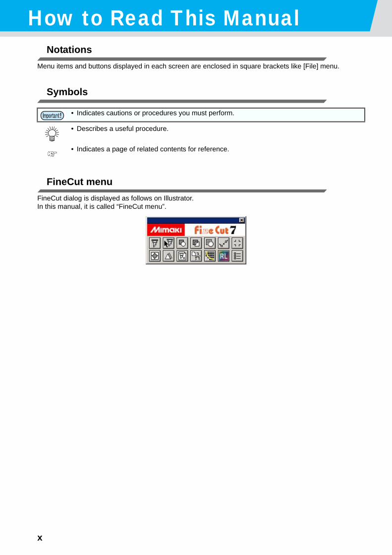
FineCut menuFineCut dialog is displayed as follows on Illustrator.In this manual, it is called “FineCut menu”.
• Indicates cautions or procedures you must perform.
• Describes a useful procedure.
• Indicates a page of related contents for reference.

This chapter describes how to install FineCut.
Installation of FineCut.............................................. 1-2For Windows .............................................................. 1-2For Macintosh ............................................................ 1-4
USB Serial Adapter for Macintosh........................... 1-6
CHAPTER 1Installation

1-2
Installation of FineCutFor Windows
1 Start the computer.
2 Set the CD-ROM of FineCut into the CD drive.
3 Click [FineCut7 for Illustrator Setup].
4 Click [Next].
5 The Software License Agreement screen appears.
Read through the agreement, and click [Yes] toconsent the agreement.

1-3
Installation of FineCut
1
Installation
6 Click [Browse].
7 Select plug-in folder of the Illustrator used.
Double-click plug-in folder, and then click [OK].
8 Click [Next]. Installation starts.
9 When the screen on the right appears, click [Close].
Installation is complete.

1-4
For Macintosh
1 Start the computer.
2 Set the CD-ROM of FineCut into the CD drive.
3 Double-click the FineCut CD icon.
4 Double-click the installer icon.
5 The software license agreement screen appears.
Read through the agreement, and click [Accept]to consent the agreement.
6 Select the type of installation, and then click [Install].
• Select [Standard Install] for the type of installa-tion.
• To change the install location, click [SwitchDisk] and select the disk.
Installation of FineCut
1-5
1
Installation
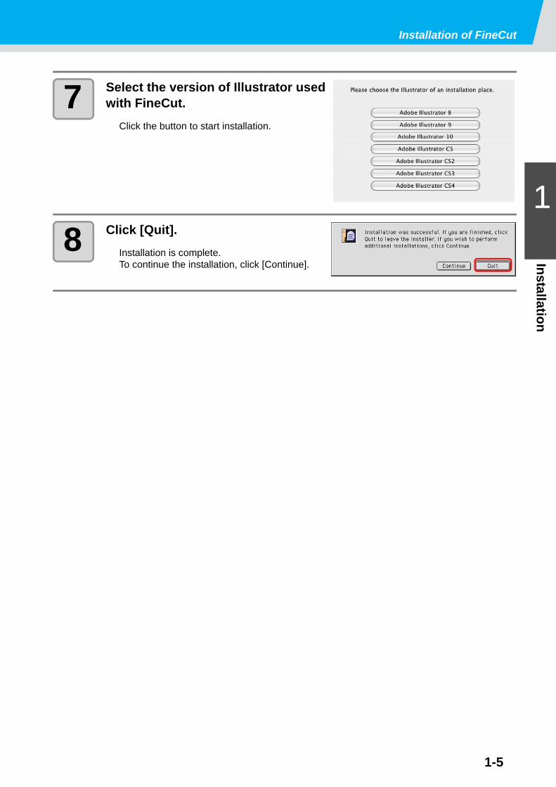
7 Select the version of Illustrator used with FineCut.
Click the button to start installation.
8 Click [Quit].Installation is complete.To continue the installation, click [Continue].

1-6
USB Serial Adapter for MacintoshTo output to a serial port of the plotter from Macintosh USB port, USB-serial adapter is required.Mimaki recommends the optional USB-serial adapter (Model number: OPTSS036).
Some USB-serial adapter may not operate normally because of a problem between the adapter and the operating system of the computer. Before using other manufacturer’s adapter, contact the manufacturer for problems between the adapter and OS in use.

This section describes basic operations, as an example of theprocedures for cutting ABC in the lower right of A3 size sheetusing MIMAKI CG cutting plotter series.
Let’s Cut! ................................................................. 2-2
CHAPTER 2Basic Operations

2-2
Let’s Cut!The following steps show how to cut ABC in the lower right of A3 size sheet using MIMAKI CG cutting plotter series.Additionally shows how to cut a frame away from surroundings of ABC by 5mm.
1 Load a A3 size sheet into the plotter so that it is wider than it is tall.
2 Set the plotter to REMOTE mode.
3 Start Illustrator and create new document.You do not need to set A3 for the paper size.
• For the sheet loading or the plotter operation, refer to the Operation Manual attached to the plotter.
• Be sure to set to REMOTE mode. In case of LOCAL mode, FineCut cannot load the length of sheet on the plotter.
A3 size sheet
Frame
2-3
Let’s Cut!
2
Basic O
perations
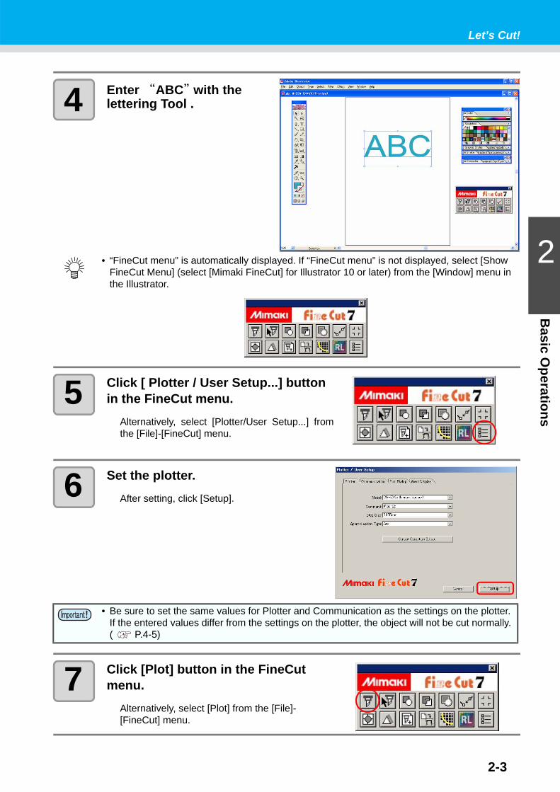
4 Enter “ABC” with the lettering Tool .
5 Click [ Plotter / User Setup...] button in the FineCut menu.
Alternatively, select [Plotter/User Setup...] fromthe [File]-[FineCut] menu.
6 Set the plotter.After setting, click [Setup].
7 Click [Plot] button in the FineCut menu.
Alternatively, select [Plot] from the [File]-[FineCut] menu.
• “FineCut menu” is automatically displayed. If “FineCut menu” is not displayed, select [Show FineCut Menu] (select [Mimaki FineCut] for Illustrator 10 or later) from the [Window] menu in the Illustrator.
• Be sure to set the same values for Plotter and Communication as the settings on the plotter. If the entered values differ from the settings on the plotter, the object will not be cut normally. ( P.4-5)
2-4
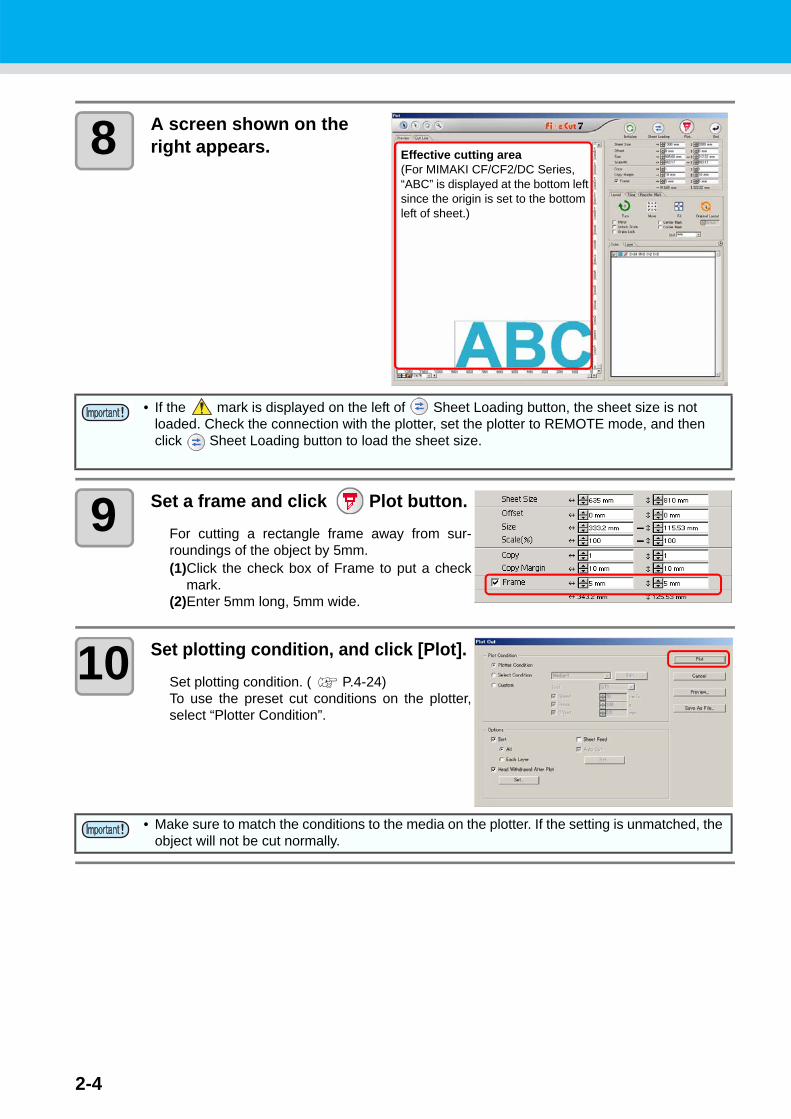
8 A screen shown on the right appears.
9 Set a frame and click Plot button.For cutting a rectangle frame away from sur-roundings of the object by 5mm.(1)Click the check box of Frame to put a check
mark.(2)Enter 5mm long, 5mm wide.
10 Set plotting condition, and click [Plot].Set plotting condition. ( P.4-24)To use the preset cut conditions on the plotter,select “Plotter Condition”.
• If the mark is displayed on the left of Sheet Loading button, the sheet size is not loaded. Check the connection with the plotter, set the plotter to REMOTE mode, and then click Sheet Loading button to load the sheet size.
• Make sure to match the conditions to the media on the plotter. If the setting is unmatched, the object will not be cut normally.
Effective cutting area(For MIMAKI CF/CF2/DC Series, “ABC” is displayed at the bottom left since the origin is set to the bottom left of sheet.)

Let’s Cut!
2-5
2
Basic O
perations
11 It starts cutting the object.The object is cut on the sheet origin - the bottomright (the bottom left for MIMAKI CF/CF2/DCseries) of the sheet.
12 Click End button.“Plot” screen is closed.

2-6

This section describes the convenient usage or settings of Fine-Cut.
Enlarge or Reduce an Object....... 3-2Put a Positioning Mark ................. 3-4Cut an Object Multiple Times (Copy) . 3-6Divide and Cut an Object (Tiling) . 3-8Create Shadow/Edge................. 3-10Extract the Outline ..................... 3-12Edit the Line ............................... 3-14Make a Precut Line around Object... 3-16Cut an Object on Each Color ..... 3-18Cut an Object on Each Layer..... 3-20Set the Output Order/Tool on Each Color/Layer ................................ 3-22Set Output Condition.................. 3-24Set Output Condition on Each Color /Layer ............................... 3-26Set Head Position and Origin after Plot............................................. 3-29Check the Cutting Process by Preview................................................... 3-31
Make Stickers or Sign-panels ... 3-34Make Effective Use of Sheet..... 3-66Trapping .................................... 3-68Recognize Stroke Weight and Overlap...................................... 3-69Import / Output Plot File ............ 3-70Output to RasterLink ................. 3-72Join paths.................................. 3-75
CHAPTER 3Advanced operations

3-2
Enlarge or Reduce an ObjectEnlarge or reduce an object on Plot screen. Click [Plot] button in the FineCut menu.
Enlarge or reduce an object with a fixed aspect ratioClick and uncheck [Unlock Scale] on the Layout tab.Enlarge or reduce an object as dragging a corner of the object.
It indicates the aspect ratio is fixed.

Enlarge or Reduce an Object
3-3
3
Advanced O
perations
Enlarge or reduce only width or length of an objectClick and check [Unlock Scale] on the Layout tab.Enlarge or reduce an object as dragging the left or right corner or the top or bottom corner of the object.
To enlarge or reduce an object more precisely, enter the values on the [Size] and the [Scale].
• To enlarge or reduce an object with the aspect ratio retained, check [Unlock Scale], and then drag an object as holding down the Shift key of the keyboard.
• To enlarge or reduce an object with the changed aspect ratio retained, change the width and length separately, and then uncheck [Unlock Scale].

3-4
Put a Positioning MarkTo affix cut stickers to the expected position, mark an object frame.
Set the marks on Plot screen. Click [Plot] button in the FineCut menu.
• When [CF3 (Milling)] is selected on Plotter / User Setup screen, this function cannot be used.
(1) Determine the center of thesticker and draw ruled lines.
(2) Align the center marks withthe ruled lines;Enables the sticker to affix tothe expected position.
(1) Draw ruled lines.(2) Align the corner marks with
the ruled lines;Enables the stickers to affixhorizontally.
Center Mark Corner Mark
Put a Positioning Mark
3-5
3
Advanced O
perations
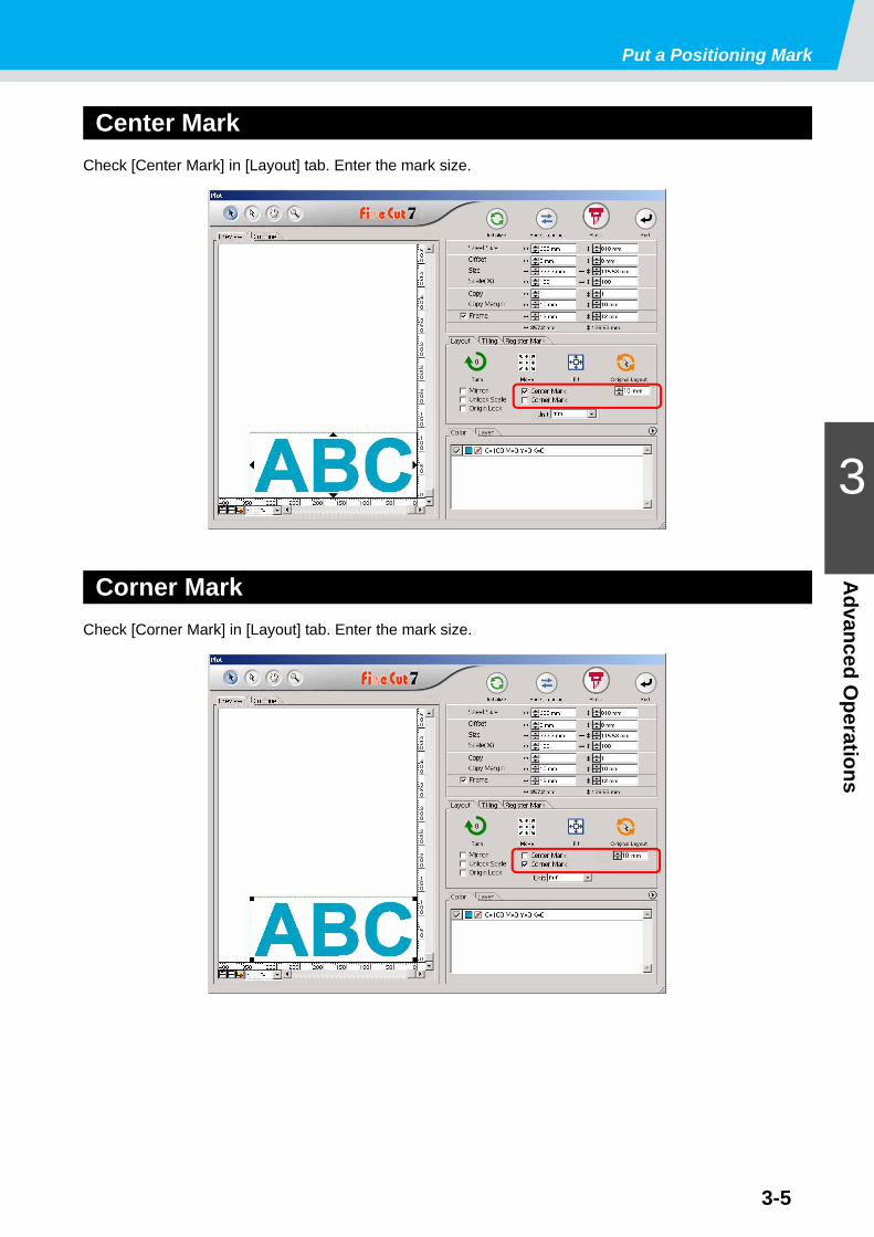
Center MarkCheck [Center Mark] in [Layout] tab. Enter the mark size.
Corner MarkCheck [Corner Mark] in [Layout] tab. Enter the mark size.

3-6
Cut an Object Multiple Times (Copy)To cut an object multiple times vertically and horizontally, use Copy.The following example shows how to cut ABC on A3 sized sheet.
1 Click [Plot] button in the FineCut menu.
2 Set [Copy] and [Copy Margin].• [Copy]
Enter value 3 for horizontal and value 4 forvertical.
• [Copy Margin]Set the margin between objects (horizontallyand vertically) to 10 mm.
3 Check [Frame] and enter 10 mm for both width and length.
The frame is put on 10 mm outside of the object.
• When Frame is set, the frame is created for each object. You cannot enclose all the copied objects with a single frame.
• When [CF3 (Milling)] is selected on Plotter / User Setup screen, note the followings.Set [Copy Margin] to 10 mm or more.Frame cannot be created.
This includes all margins of the object.
This includes the frame size.
Cut an Object Multiple Times (Copy)
3-7
3
Advanced O
perations
4 Click Plot button.The objects are plotted.

3-8
Divide and Cut an Object (Tiling)To create an object larger than the sheet width (signboard, etc.), divide and cut the object with Tiling.
In this section, each divided object is called “Tile”.
1 Click [Plot] button in the FineCut menu.
2 Click [Tiling] tab.
3 Set how to separate, and click [Separation].
( P.4-20 for details)
4 Divided objects are displayed.Set the tile position or others.
( P.4-21 for details)
Set how to separate

Divide and Cut an Object (Tiling)
3-9
3
Advanced O
perations
5 Select tiles to cut from the tile list.
6 Click Plot button.The objects are plotted.
Select

3-10
Create Shadow/EdgeCreate shadow/edge of an object.
1 Select an object on Illustrator.
2 Click [Create Shadow/ Edge] button in the FineCut menu.
Alternatively, select [Create Shadow/ Edge] fromthe [File]-[FineCut] menu.
3 Select and set shadow or edge, and click [OK].
Item Description1 Shape Select shadow type (4types) or edge.2
Options
Set the offset distance between the object and shadow/edge.For “Perspective”, set the perspective by %.For “Edge”, set the shape of the corner and the ratio.( P.3-36 "1. Attach a Frame (Cutting line)" for reference.)
3
Color
Set the color of shadow.Click the color to display the following screen.Select color or input the number, and click [OK].
• Specify RGB colors for the shadow/edge. If the object color mode is CMYK, it may not be able to display by the specified RGB colors.In this case, it is converted to the representable colors of the nearest CMYK.
Drag the path to move the object or to change the shape
1 2 3

Create Shadow/Edge
3-11
3
Advanced O
perations
4 A shadow or an edge is created.The example shown on the right is set as follows;Shape: DropOffset: 4mm eachColor: Black
• If the shadow or edge has a lot of anchor points, execute Illustrator-[Object]-[Path]-[Simplify...].
• To remove the created shadow or edge, select [Remove Shadow / Edge] from the [File]-[FineCut] menu.
• If you edit the created shadow or edge on Illustrator, you may not be able to delete it.

3-12
Extract the OutlineCreate the outline to cut the bitmap image. And you can specify a color for creation of the outline only in the same color area.
1 Select an object on Illustrator.
2 Click [Outline Extraction] button in the FineCut menu.
Alternatively, select [Outline Extraction] from the[File]-[FineCut] menu.
3 Set the selection method of the area to be extracted.
( P.4-27)
4 Adjust the extraction area while previewing the image.
5 Set [Trace Setting].
( P.4-28)

Extract the Outline
3-13
3
Advanced O
perations
6 Click [Trace execute] button.
7 Outline is created on the [FC Trace Layer] of Illustrator.
• Clicking [Trace Execute], a new layer is created as [FC Trace layer 1], [FC Trace layer 2...]. Use this function to set cutting condition for each layer. ( P.3-26, P.3-64)
• The data in this layer is set to non-printing, since it is used as cutting data.To print this data, enable “Print” on Illustrator “Layer option”.

3-14
Edit the LineThe outline created by Outline Extraction can be modified or changed.
1 Open an image created by Outline Extraction on Illustrator.
If necessary, enlarge the line to be edited withthe zoom tool of Illustrator.
2 Click [Line Edit Tool] button on Illustrator Tool Palette.
The line edit tool appears. ( P.4-32)
3 Specify [Start Point] and [End Point].
Start Point Move the cursor close to the anchor point to show “S”. Click the anchor point to set the start point.
End PointAfter setting the start point, move the cursor close to the anchor point toshow “E”.Click the anchor point to set the end point.

Edit the Line
3-15
3
Advanced O
perations
4 Select the operation.This is an example of [Change curve].
5 Drag the line to curve.The line is fixed when the mouse button is up.
• Check [Use shortcut key] to edit with keys shown on the right of each operation. Use Alt key for Windows and Option key for Macintosh respectively.

3-16
Make a Precut Line around ObjectWhen creating stickers, precut line (called “Weed line”) around the object enables to tear off the sticker with ease.This section describes how to make weed line and frame.
1 Select an object on Illustrator.
2 Click [Create Weed Line] button in the FineCut menu.
Alternatively, select [Create Weed Line] from the[File]-[FineCut] menu.
3 Set the Weed Line.After setting, click [OK] .
• Do not set the weed line on a thick sheet. The line may damage the object.
• The unit used in “Make Weed Line” screen refers to the setting of Illustrator. If changing the unit, set in the Illustrator-[File]-[Preferences]-[Units & Undo].
Item Description1 Preview Check the position and the number of the weed line.2 Frame Offset Set the distance between the object and the frame.3
Interval
[Free]Make the line on the needed position with the needed numbers.Select the direction of the line in [Direction], and click on the previewto make the line.[Divide]Set the divide number to both horizontal and vertical directions.[Distance]Set the distance in between the objects to both horizontal andvertical directions.
4 Clear Delete all weed lines except frames5 Direction Select the direction of weed line to be created. It is used when
[Free] is selected on [Interval].
1
2 3
45
Make a Precut Line around Object
3-17
3
Advanced O
perations
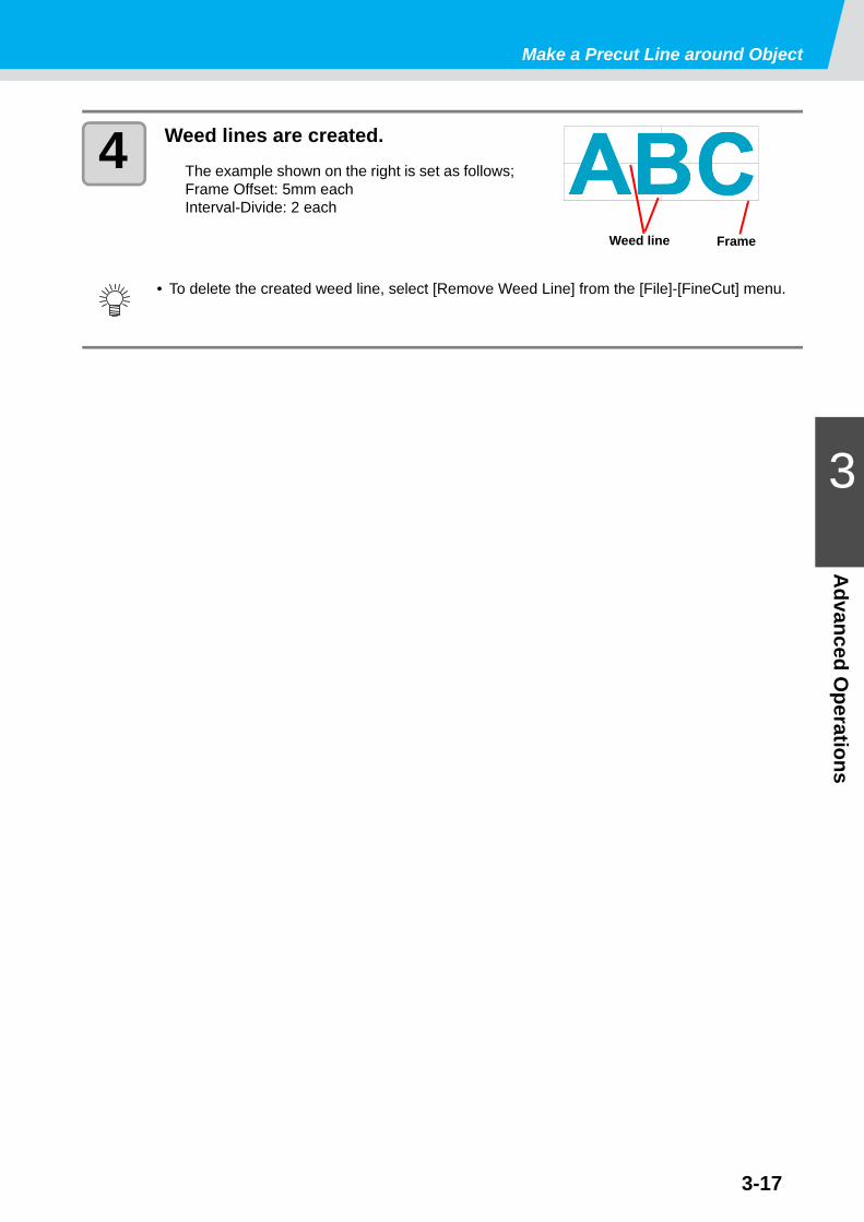
4 Weed lines are created.The example shown on the right is set as follows;Frame Offset: 5mm eachInterval-Divide: 2 each
• To delete the created weed line, select [Remove Weed Line] from the [File]-[FineCut] menu.
Weed line Frame

3-18
Cut an Object on Each ColorIf an object consists of multiple colors on Illustrator, you can cut out the specified color object.
This describes how to cut out the Cyan (C=100%) colored object “ABC” with the following example.
1 Select an object on Illustrator.
2 Click [Plot] button in the FineCut menu.
3 Uncheck the color set (DIC 80p) of “DEF” on the example above.
Object “DEF” disappears from the cutting area.
• Color ListThe color list displays all colors (including PANTONE and other special colors) used for the object. It also displays the colors of fill and strokes of the object.To specify the output condition, click the button on the upper right of the list.
C=100%
DIC=80p
Click to display the stroke color information.
Click to display the fill color information.
Cut an Object on Each Color
3-19
3
Advanced O
perations
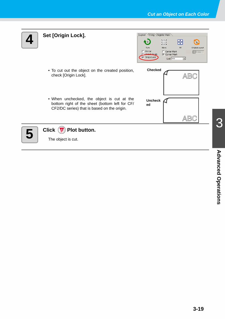
4 Set [Origin Lock].
• To cut out the object on the created position,check [Origin Lock].
• When unchecked, the object is cut at thebottom right of the sheet (bottom left for CF/CF2/DC series) that is based on the origin.
5 Click Plot button.The object is cut.
Checked
Unchecked

3-20
Cut an Object on Each LayerIf an object consists of multiple layers on Illustrator, you can cut out the object on the specified layer.
This describes how to cut out “ABC” on the layer 1 of the following example.
1 Select an object on Illustrator.
2 Click [Plot] button in the FineCut menu.
3 Click [Layer] and uncheck the layer of “DEF” on the example above.
Object “DEF” on the layer disappears fromthe cutting area.
Layer 1
Layer 2

Cut an Object on Each Layer
3-21
3
Advanced O
perations
4 Set [Origin Lock].
• To cut out the object on the created position,check [Origin Lock].
• When unchecked, the object is cut at thebottom right of the sheet (bottom left for CF/CF2/DC series) that is based on the origin.
5 Click Plot button.The object is cut.
Checked
Unchecked

3-22
Set the Output Order/Tool on Each Color/LayerOutput order can be specified by color or layer.The order of the several tools’ operation can also be set by color or layer.
Normally, objects are output in order, from the bottom to the top of the color/ layer list.
This describes how to cut the red frame first with the tool [HLF] of the following example.
1 Select an object on Illustrator.
2 Click [Plot] button in the FineCut menu.
3 Drag the red in the color list to the bottom.
4 Click the upper right button of the list and select [Specify The Tool On Each Color (or Layer)].

Set the Output Order/Tool on Each Color/Layer
3-23
3
Advanced O
perations
5 Select [HLF] for tool.
6 Click Plot button.
7 Check [Sort] on Plot Out screen, and select [Each Color (or Each Layer)].
8 Click [Plot] button.
The object is output in the specified order.

3-24
Set Output ConditionOutput condition can be set by the media used.
1 Click [Plotter/User Setup...] button in the FineCut menu.
2 Click [Output Condition Setup...].Alternatively, click [Edit] button in the Plot Outscreen. ( P.4-24)
3 Set conditions on Output Condition Setup screen.Setting items differ depending on the model selected on [Model] of Plotter / User Setupscreen (See step 2). Set items and click [Setup]. ( P.4-6.)
4 Click [Plot] button in the FineCut menu.
5 Click Plot button on Plot screen.
• This function is effective only for the MGL-IIc commands.• In case any setting value exceeds the limit value of the plotter, the object is plotted with the
limit value of the plotter. For the limit values, refer to the Operation Manual of the plotter.
• Once output conditions are set for each media with the following steps, the conditions can be changed by media on Plot Out screen. ( next page).
Set Output Condition
3-25
3
Advanced O
perations
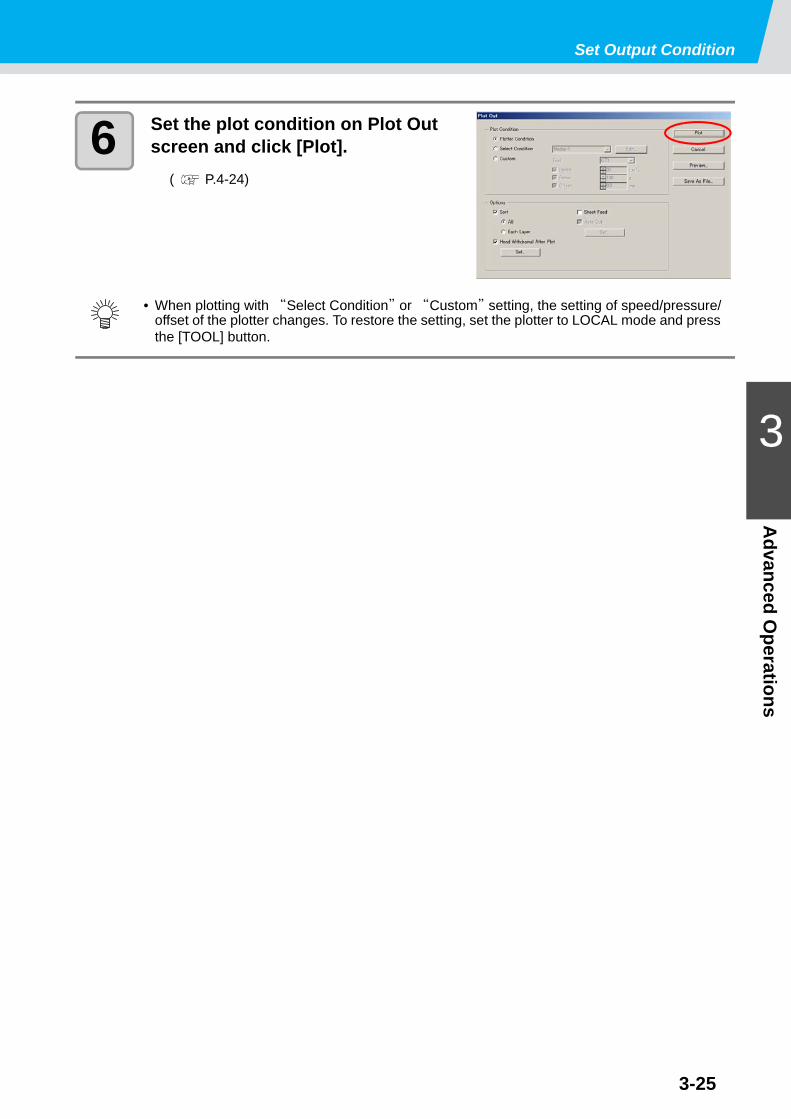
6 Set the plot condition on Plot Out screen and click [Plot].
( P.4-24)
• When plotting with “Select Condition” or “Custom” setting, the setting of speed/pressure/offset of the plotter changes. To restore the setting, set the plotter to LOCAL mode and press the [TOOL] button.

3-26
Set Output Condition on Each Color /LayerOutput condition can be set on each color or layer. For a fine object or small characters, create an object on each color or layer, and set the appropriate output condition (lowering cutting speed, etc.) for each. The objects can be cut finely.In CF/CF2/DC/CF3 series, you can cut and make ruled line at one time by specifying tools on each color or layer.
1 Click the button on the upper right of the color list (or layer list).
2 Select [Specify The Plot Condition (Tool) On Each Color (Layer)].
3 If the following screen appears, click [OK] .
When [Specify The Plot Condition On Each Layer (Color)] is selected:
When [Specify The Tool On Each Layer (Color)] is selected:
When CF3/CJV30/TPC series is used
3-27
Set Output Condition on Each Color /Layer
3
Advanced O
perations
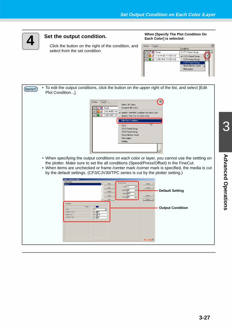
4 Set the output condition.Click the button on the right of the condition, andselect from the set condition.
• To edit the output conditions, click the button on the upper right of the list, and select [Edit Plot Condition...].
• When specifying the output conditions on each color or layer, you cannot use the settting on the plotter. Make sure to set the all conditions (Speed/Press/Offset) in the FineCut.
• When items are unchecked or frame /center mark /corner mark is specified, the media is cut by the default settings. (CF3/CJV30/TPC series is cut by the plotter setting.)
When [Specify The Plot Condition On Each Color] is selected:
Default Setting
Output Condition

Set Output Condition on Each Color /Layer
3-28
5 Click Plot button.
6 Click [Plot].

3-29
3
Advanced O
perationsSet Head Position and Origin after Plot
You can set the head position after plot.
1 Select an object on Illustrator.
2 Click [Plot] button in the FineCut menu.
3 Click Plot button on Plot screen.
4 Check [Head Withdrawal After Plot].To change the head withdrawal position or to setthe origin to the withdrawal position, click [Set]and go to the next step.

Set Head Position and Origin after Plot
3-30
5 Change the setting on Head With-drawal Position screen.
After setting, click [Setup].
6 Click [Plot] on Plot Out screen.Plot starts. The plotter head moves to the specified position after plotting.
Item Description1 Set the head withdrawal position for the horizontal direction from
the reference position (Select [Current Origin] or [Max Cut Width]).2 Set the head withdrawal position for the length direction from the
reference position (Select [Current Origin] or [Max Cut Length]).3
Sheet Feed Origin Renewal
Set the head withdrawal position as the origin position.(Effective only for the MGL-IIc commands on CG/ CJV30 seriesand TPC.)Check this to prevent from cutting on the same position with theprevious cut when plotting continuously with the same sheet.
• When using [No. COPIES] or [DIVISION CUT] of the plotter, uncheck the [Sheet Feed Origin Renewal].If it is checked, [No. COPIES] or [DIVISION CUT] will not perform normally.
1
2
3

3-31
3
Advanced O
perationsCheck the Cutting Process by Preview
Before cutting objects, you can check the plot process with your plot setting by Preview.
1 Select an object on Illustrator.
2 Click [Plotter/User Setup...] button in the FineCut menu.
3 Click [Output Condition Setup...] and set the output condition.
( P.4-6)
4 Click [Plot] button in the FineCut menu.
5 Click Plot button on Plot screen.
6 Set the plot condition in Plot Out screen, and click [Preview].
( P.4-24 for details of the setting)

3-32
7 Check the cutting line by the pre-view.
8 Click in [Simulation] and check the moves of cutting.To return to the state before cutting, click . To go to the state after cutting, click .Slide bar shows the simulation from random position.To set the speed of the simulation, set [Playback Speed].
9 If needed, go back to Step 1 to Step 6 and adjust the plot condition.
• To change the color of [Display Setting], click the color on the right of each setting.• When copy /mark separation is set, the preview displays the object without copy /mark
separation.
Item DescriptionCutting Direction Shows black line for cutting in anticlockwise, and red line
for cutting in clockwise.Checking [Arrows], cutting direction shows with arrows.• In case of open path, both directions display in black.
Start Position Shows blue for starting point of cutting.Move Shows yellow for moving line raising the tool.
Cutting Order Shows numbers for cutting order.Tool Position Shows green for a tool (head) position. Displaying simula-
tion, you can check the moving of the tool.Show Original Shows the Illustrator object that is ready by FineCut and
processed on Plot screen in the state before cutting.
• For CF series, you can check the Cut start position on the preview.To adjust it, go to [Optimize Cutting Start Position] of Plot Out screen. ( P.4-26)
• For CF3 (Milling), you can check the following settings on the preview.Cut start position:To adjust it, go to [Optimize Cutting Start Position] of Plot Out screen. ( P.4-26)Offset / Cutting direction:To adjust it, go to [Options] of Plot Out screen. ( P.4-25)Position of cutting line:To adjust it, go to [End Mill Diameter] of Output Condition Setup screen. ( P.4-10)

Check the Cutting Process by Preview
3-33
3
Advanced O
perations
10 Check the preview again, and click [Close].
11 Click [Plot] in Plot Out screen to start cutting.
3-34
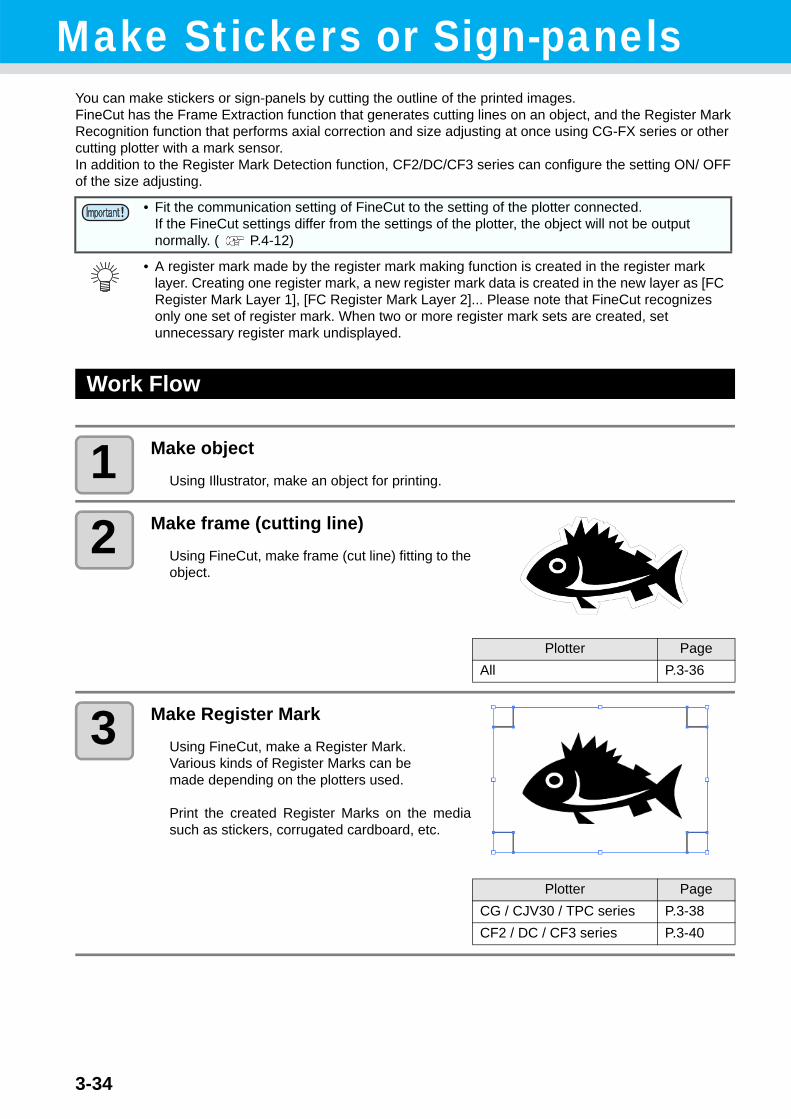
Make Stickers or Sign-panelsYou can make stickers or sign-panels by cutting the outline of the printed images.FineCut has the Frame Extraction function that generates cutting lines on an object, and the Register Mark Recognition function that performs axial correction and size adjusting at once using CG-FX series or other cutting plotter with a mark sensor.In addition to the Register Mark Detection function, CF2/DC/CF3 series can configure the setting ON/ OFF of the size adjusting.
Work Flow
1 Make object
Using Illustrator, make an object for printing.
2 Make frame (cutting line)Using FineCut, make frame (cut line) fitting to theobject.
3 Make Register MarkUsing FineCut, make a Register Mark.Various kinds of Register Marks can bemade depending on the plotters used.
Print the created Register Marks on the mediasuch as stickers, corrugated cardboard, etc.
• Fit the communication setting of FineCut to the setting of the plotter connected. If the FineCut settings differ from the settings of the plotter, the object will not be output normally. ( P.4-12)
• A register mark made by the register mark making function is created in the register mark layer. Creating one register mark, a new register mark data is created in the new layer as [FC Register Mark Layer 1], [FC Register Mark Layer 2]... Please note that FineCut recognizes only one set of register mark. When two or more register mark sets are created, set unnecessary register mark undisplayed.
Plotter PageAll P.3-36
Plotter PageCG / CJV30 / TPC series P.3-38CF2 / DC / CF3 series P.3-40

3-35
Make Stickers or Sign-panels
3
Advanced O
perations
4 Cut the objectSet the printed media on the plotter used, and cut it.You can cut the various media such as stickers, corrugated cardboard, etc.
Function Plotter PageRecognize and cut Register Mark CG-EX P.3-42
Cut continuously CG-FX / 75ML / 60SR /SRII,CJV30 / TPC series P.3-44
Cut with ID certification mode CG-75ML P.3-50
Cut the outline and base sheet at a time CG-75ML / 60SR /SRII, CJV30 / TPC series P.3-54
Cut with CF2 / DC / CF3 series CF2 / DC / CF3 series P.3-56Cut with end mill -- P.3-58
3-36
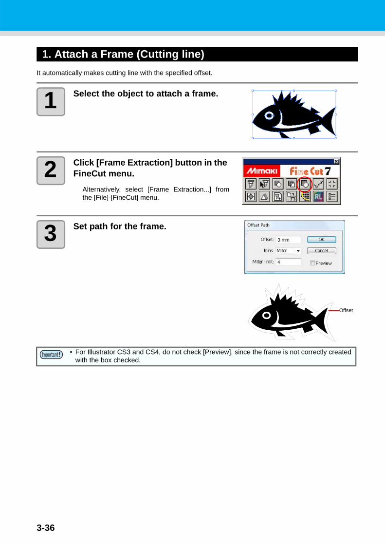
1. Attach a Frame (Cutting line)It automatically makes cutting line with the specified offset.
1 Select the object to attach a frame.
2 Click [Frame Extraction] button in the FineCut menu.
Alternatively, select [Frame Extraction...] fromthe [File]-[FineCut] menu.
3 Set path for the frame.
• For Illustrator CS3 and CS4, do not check [Preview], since the frame is not correctly created with the box checked.
Offset

3-37
Make Stickers or Sign-panels
3
Advanced O
perations
4 Click [OK].The frame is extracted, and a path is created in [FC Frame Layer].
Item DescriptionOffset Set the distance from the object to the frame.
For bleed, enter a negative value.Joins Set the shape of frame corners.
• If the frame shape is not natural, change the Joins to improve it. Generally, the more acute corner and the larger offset, the less accuracy.
Miter limit Set the ratio up to the two line ends crossed position.(Effective only for the Miter shape.)A larger value makes the corner more acute.
• Every time executing [Frame Extraction], a new layer is created as “FC Frame Layer 1”, “FC Frame Layer 2”.Use it when setting print or cutting condition for each layer. ( P.3-26, P.3-72)
• The data in this layer is set as non-printed, since it is used as cutting data.To print this data, enable “Print” on Illustrator “Layer option”.
Miter BevelRound
Example: 10mm1mm

3-38
2-1. Make a Register Mark (CG/CJV30/TPC series)
1 Enclose an object with rectangle on the position for making a register mark.
Select the layer of the object to be printed, andthen make a rectangle for register mark with therectangle tool.
2 Click [Register Mark Creation] button in the FineCut menu.
Alternatively, select [Register Mark Creation]from the [File]-[FineCut] menu.
3 Set the shape or others for the regis-ter mark.
Click [OK] after setting.
Item DescriptionMark Shape Select the shape of the register mark.Mark Size Set the size of the register mark.Line Width Set the line width of the register mark.
Leave a rectangle as the cutting line Cuts the rectangle created in step 1.
Fill around the register mark
Fills around the register mark with red spot color.When register mark is not recognized on the media ofother than white, the mark can be recognized with thisfunction.
• Recommend color to fill around is red (default) or white. To print with white, refer to the printer manual. Generally allocate red spot color to white and print.

3-39
Make Stickers or Sign-panels
3
Advanced O
perations
4 A register mark is created. Output this data to the printer.
The register mark is created in the layer of theobject.
• When register mark is not recognized filling around the mark with red or white, it will not improve with the other colors. Furthermore, some types of media or inks may not recognize the register mark even if the color around the mark is changed.
• When cutting continuously ( P.3-44, P.3-50) with this function, do not gap between register marks.
Item DescriptionAdd the pattern information
(Only for CG-75ML)Adds a bar-code shaped pattern information with registermark.With the pattern information and the register mark readingfunction, you can cut the outline of multiple different stickerat one time.
When register shape is When register shape is
No gap between the register marks

3-40
2-2. Make a Register Mark (CF2/DC/CF3 series)
1 Enclose an object with rectangle on the position for making a register mark.
Select the layer of the object to be printed, andthen make a rectangle for register mark with therectangle tool.
2 Click [Register Mark Creation] button in the FineCut menu.
Alternatively, select [Register Mark Creation] from the [File]-[FineCut] menu.

3-41
Make Stickers or Sign-panels
3
Advanced O
perations
3 Set the size of register mark.Click [OK] after setting.
4 A register mark is created. Output this data to the printer.
The register mark is created in the layer of theobject.
Item DescriptionMark Size Set the size of the register mark.
Mark Separation Cuts each separated area.Use it when an object is too large to fit in the cut area.
• For the figure below, it is cut in 3 times of 1 to 3. ( P.3-63)
• The position of the separated mark can be moved by selecting with [Direct selection tool] of Illustrator.To change the position of the marks, align them on the same line in the separated direction (Vertical for the figure above).Marks of left and right (or above and below) make a pair. To change a mark position, move them together.
Separation Mark
3
2
1
3-42
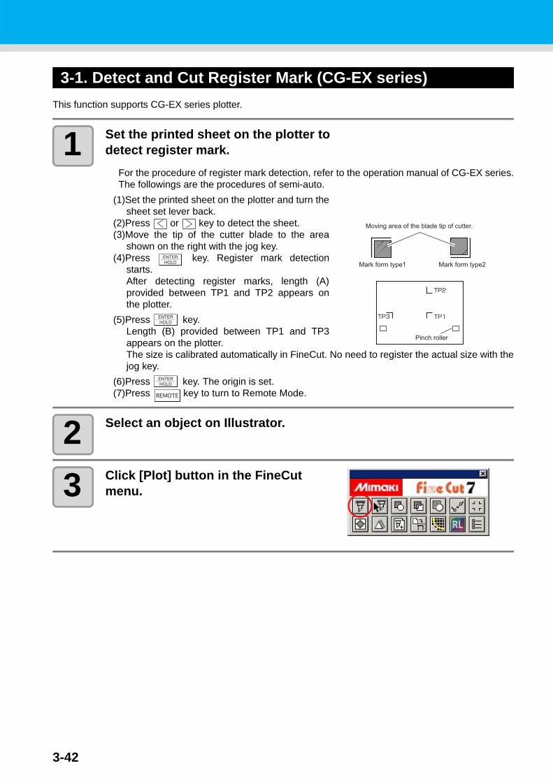
3-1. Detect and Cut Register Mark (CG-EX series)This function supports CG-EX series plotter.
1 Set the printed sheet on the plotter to detect register mark.
For the procedure of register mark detection, refer to the operation manual of CG-EX series.The followings are the procedures of semi-auto.
(1)Set the printed sheet on the plotter and turn thesheet set lever back.
(2)Press or key to detect the sheet.(3)Move the tip of the cutter blade to the area
shown on the right with the jog key.(4)Press key. Register mark detection
starts.After detecting register marks, length (A)provided between TP1 and TP2 appears onthe plotter.
(5)Press key.Length (B) provided between TP1 and TP3appears on the plotter.The size is calibrated automatically in FineCut. No need to register the actual size with thejog key.
(6)Press key. The origin is set.(7)Press key to turn to Remote Mode.
2 Select an object on Illustrator.
3 Click [Plot] button in the FineCut menu.
3-43
Make Stickers or Sign-panels
3
Advanced O
perations
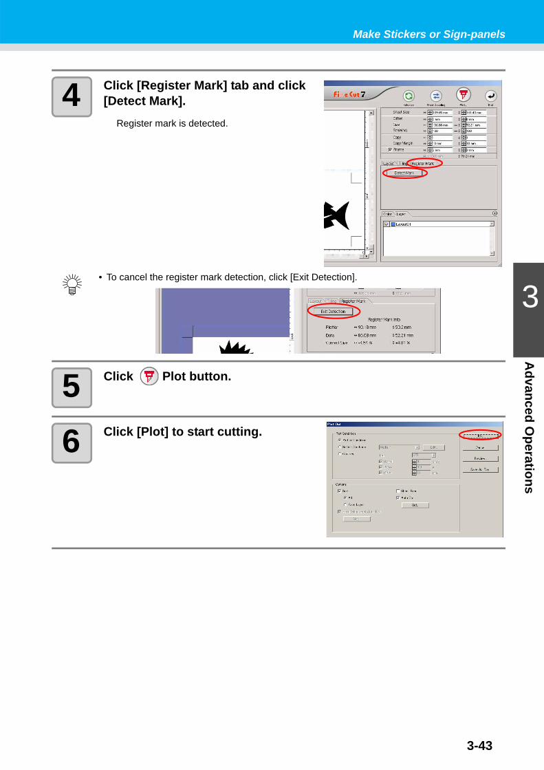
4 Click [Register Mark] tab and click [Detect Mark].
Register mark is detected.
5 Click Plot button.
6 Click [Plot] to start cutting.
• To cancel the register mark detection, click [Exit Detection].
3-44
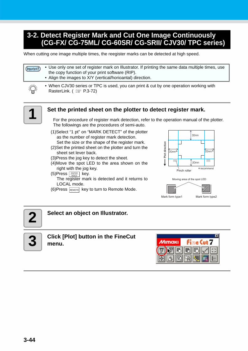
3-2. Detect Register Mark and Cut One Image Continuously(CG-FX/ CG-75ML/ CG-60SR/ CG-SRII/ CJV30/ TPC series)
When cutting one image multiple times, the reegister marks can be detected at high speed.
1 Set the printed sheet on the plotter to detect register mark.For the procedure of register mark detection, refer to the operation manual of the plotter.The followings are the procedures of semi-auto.
(1)Select “1 pt” on “MARK DETECT” of the plotteras the number of register mark detection.Set the size or the shape of the register mark.
(2)Set the printed sheet on the plotter and turn thesheet set lever back.
(3)Press the jog key to detect the sheet.(4)Move the spot LED to the area shown on the
right with the jog key.(5)Press key.
The register mark is detected and it returns toLOCAL mode.
(6)Press key to turn to Remote Mode.
2 Select an object on Illustrator.
3 Click [Plot] button in the FineCut menu.
• Use only one set of register mark on Illustrator. If printing the same data multiple times, use the copy function of your print software (RIP).
• Align the images to X/Y (vertical/horioantal) direction.
• When CJV30 series or TPC is used, you can print & cut by one operation working with RasterLink. ( P.3-72)

3-45
Make Stickers or Sign-panels
3
Advanced O
perations
4 Click [Register Mark] tab and click [Detect Mark].
Register mark is detected.
5 Set the register mark to detect con-tinuously.
To cancel the register mark detection, click [ExitDetection].
6 Click Plot button.
Item DescriptionRoll Sheet/Leaf Sheet Select the sheet to cut.
Repeat
• Roll SheetSet the data numbers to vertical and horizontal direction.
• Leaf SheetSet the sheet numbers to replace.
In case the number is indefinite, input the maximum numbers“9999”.
Search Position
• First TimeSelect the first detection points of the register mark.
• ContinueSelect the second and the subsequent detection points of the register mark.
• When detecting a large data, increase the mark detection points to cut more precisely.When detecting a small data, decrease the detection points of “Continue” to reduce the detecting time.
Leaf SheetRoll Sheet

3-46
7 Click [Plot] to start cutting.
In case of Auto Cut• Checking on [Auto Cut] in Plot Out screen enables sheet to cut automatically after each
cutting.To execute auto cut, make sure to check [Auto Cut] in this screen.Even if ON is set on the plotter, auto cut is invalid unless [Auto Cut] is checked on Plot Out screen. Even if OFF is set on the plotter, auto cut is valid with [Auto Cut] checked on Plot Out screen.
• Click [Set...] below [Auto Cut] on the screen, and set in detail as follows.
Set the length from the last line to the cutting point. (See the figure A below).
Check to cut the data at every line. (See blue line below)
<Cut
<Cut
<Cut
A
3-47
Make Stickers or Sign-panels
3
Advanced O
perations
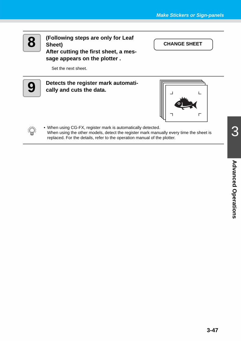
8 (Following steps are only for Leaf Sheet)After cutting the first sheet, a mes-sage appears on the plotter .
Set the next sheet.
9 Detects the register mark automati-cally and cuts the data.
• When using CG-FX, register mark is automatically detected.When using the other models, detect the register mark manually every time the sheet is replaced. For the details, refer to the operation manual of the plotter.
CHANGE SHEET

3-48
When the sheet printed by the printer with take-up function (JV series etc.) is rolled on a paper tube
Setting the 180-degree rotation in the FineCut, you can set the paper tube on the plotter without rewinding the roll sheet, and cut it.
1 Set the rotate button to 180-degree.
2 Click [Register Mark] tab and click [Detect Mark].
Register mark is detected.
3 When plot is started, the object is rotated as the figure on the right and cut.
Printer
Out
put D
irect
ion
Confirm the margin on the sheet.( P.3-44)
Plotter
Plot
Dire
ctio
n

3-49
Make Stickers or Sign-panels
3
Advanced O
perations
When the continuously printed data does not fill a part of the linesCut the data in twice to cut all the data.
Printer PlotterO
utpu
t Dire
ctio
n
Plot
Dire
ctio
n
Second cutting data
First cutting data
3-50
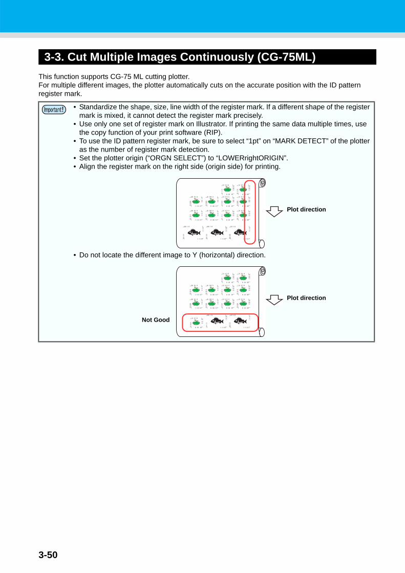
3-3. Cut Multiple Images Continuously (CG-75ML)This function supports CG-75 ML cutting plotter.For multiple different images, the plotter automatically cuts on the accurate position with the ID pattern register mark.
• Standardize the shape, size, line width of the register mark. If a different shape of the register mark is mixed, it cannot detect the register mark precisely.
• Use only one set of register mark on Illustrator. If printing the same data multiple times, use the copy function of your print software (RIP).
• To use the ID pattern register mark, be sure to select “1pt” on “MARK DETECT” of the plotter as the number of register mark detection.
• Set the plotter origin (“ORGN SELECT”) to “LOWERrightORIGIN”.• Align the register mark on the right side (origin side) for printing.
• Do not locate the different image to Y (horizontal) direction.
Plot direction
Plot direction
Not Good

3-51
Make Stickers or Sign-panels
3
Advanced O
perations
1 Set the printed sheet on the plotter to detect register mark.For the procedure of register mark detection, refer to the operation manual of the plotter.The followings are the procedures of semi-auto.
(1)Select “1 pt” on “MARK DETECT” of the plotteras the number of register mark detection.Set the size or the shape of the register mark.
(2)Set the printed sheet on the plotter and turn thesheet set lever back.
(3)Press the jog key to detect the sheet.(4)Move the spot LED to the area shown on the
right with the jog key.(5)Press key.
The register mark is detected and it returns toLOCAL mode.
(6)Press key to turn to Remote Mode.
2 Select an object on Illustrator.
3 Click [Plot] button in the FineCut menu.
• When loading the media in a direction opposite to the print, be sure to detect the register mark at the lower left.
Plot direction
Opposite direction Same direction

3-52
4 Click [Register Mark] tab and click [Detect Mark].
Register mark is detected.
5 Confirm that [ID Certification Mode] is checked.
6 Click Plot button.
7 Click [Plot].Data is sent and the plotter enters Local mode.
8 Repeat the step 2 to 6 for the other data to be cut continuously at a time.
• In case of cutting with ID certification mode, rotating direction is recognized automatically.
• Sending order of data is not necessary to be same as the order of printing.

3-53
Make Stickers or Sign-panels
3
Advanced O
perations
9 Press [REMOTE] button on the plotter.Cutting starts.

3-54
3-4. Cut Outline and Make Cutline for the Base Sheet at a Time (CG-75ML/ CG-60SR/ CG-SRII/ CJV30 / TPC series)
Outline of sticker and dotted line to separate base sheet (called HALF cut) can be cut at a time.
1 Create data with the multiple layers on the Illustrator.
Example:FC frame layer --> Outline of stickerLayer1 --> Cutline to separate the base sheet
2 Click [Plot] button in the FineCut menu.
3 Set the cutting condition for each layer.
Example:(1) Select [Specify the tool on each layer](2) For FC frame layer --> Select [CT1]
For Layer 1 --> Select [HLF]
See the following page for details. P.3-26 "Set Output Condition on Each
Color /Layer"
Outline of sticker Cutline for base sheet
1
2
3-55
Make Stickers or Sign-panels
3
Advanced O
perations
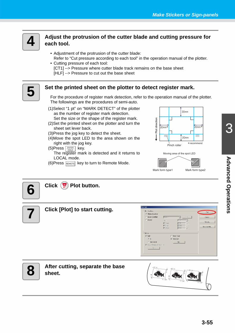
4 Adjust the protrusion of the cutter blade and cutting pressure for each tool.
• Adjustment of the protrusion of the cutter blade:Refer to “Cut pressure according to each tool” in the operation manual of the plotter.
• Cutting pressure of each tool:[CT1] --> Pressure where cutter blade track remains on the base sheet[HLF] --> Pressure to cut out the base sheet
5 Set the printed sheet on the plotter to detect register mark.For the procedure of register mark detection, refer to the operation manual of the plotter.The followings are the procedures of semi-auto.
(1)Select “1 pt” on “MARK DETECT” of the plotteras the number of register mark detection.Set the size or the shape of the register mark.
(2)Set the printed sheet on the plotter and turn thesheet set lever back.
(3)Press the jog key to detect the sheet.(4)Move the spot LED to the area shown on the
right with the jog key.(5)Press key.
The register mark is detected and it returns toLOCAL mode.
(6)Press key to turn to Remote Mode.
6 Click Plot button.
7 Click [Plot] to start cutting.
8 After cutting, separate the base sheet.

3-56
3-5. Cut Images (CF2/DC/CF3 (Except M-Head) series)
1 Set the printed sheet on the plotter to detect register mark.For the procedure of register mark detection, refer to the operation manual of the plotter.The followings are the procedures of semi-auto.
(1)Select “1 pt” on “MARK DETECT” of the plotteras the number of register mark detection.Set the size of the register mark.(Set the same size as step 3 of P.3-40)
(2)Set the printed sheet on the plotter.(3)Press key to detect the register mark.(4)Move the spot LED to the area shown on the
right with the jog key.(5)Press key.
The register mark is detected and it returns toLOCAL mode.
(6)Press key to turn to Remote Mode.
2 Select the object of step 1 on Illustrator.
3 Click [Plot] button in the FineCut menu.
4 Click Rotation button to adjust the direction of the image on the plot-ter with the display of FineCut.
5 Click [Register Mark] tab and click [Detect Mark].
Register mark is detected.
Make space nearly the size of the register mark
Moving area of spot LED
Register Mark
Spot LED

3-57
Make Stickers or Sign-panels
3
Advanced O
perations
6 Select the cutting type.• Recognize mark and cut.( P.3-62)• Cut continuously under [Multi Mode].
( P.3-62)• Cut continuously under [Single Mode].
( P.3-62)• Adjust the size. ( P.3-63)• Separate mark and cut. ( P.3-63)• Cut from the reverse. ( P.3-64)
7 Check [FC Frame Layer] only, then click Plot button.
8 Click [Plot] to start cutting.

3-58
3-6. Cutting with End Mill
1 Set Z axis origin to a plotter.Refer to the operation manual of the plotter for the detail.
2 Set the printed sheet on the plotter to detect register mark.For the procedure of register mark detection, refer to the operation manual of the plotter.The followings are the procedures of semi-auto.
(1)Select “1 pt” on “MARK DETECT” of the plotteras the number of register mark detection.Set the size of the register mark.(Set the same size as step 3 of P.3-40)
(2)Set the printed sheet on the plotter.(3)Press key to detect the register mark.(4)Move the spot LED to the area shown on the
right with the jog key.(5)Press key.
The register mark is detected and it returns toLOCAL mode.
(6)Press key to turn to Remote Mode.
3 Select the object of step 2 on Illustrator.
4 Click [Plot] button in the FineCut menu.
5 Click Rotation button to adjust the direction of the image on the plot-ter with the display of FineCut.
Make space nearly the size of the register mark
Moving area of spot LED
Register Mark
Spot LED

3-59
Make Stickers or Sign-panels
3
Advanced O
perations
6 Click [Register Mark] tab and click [Detect Mark].
Register mark is detected.
7 Select the cutting type.• Recognize mark and cut.( P.3-62)• Cut continuously under [Multi Mode].
( P.3-62)• Cut continuously under [Single Mode].
( P.3-62)• Adjust the size. ( P.3-63)• Separate mark and cut. ( P.3-63)(Reverse Cut cannot be used)
8 Check [FC Frame Layer] only, then click Plot button.
9 Select [Plot Condition] on Plot Out screen.
Select the plot condition set in FineCut. Click [Edit...] to add a media or to set cuttingcondition by each media. ( P.4-6)
• To set the plot condition on each color /layer, select [Specify The Plot Condition On Each Color / Layer] on Plot screen and set them. ( P.3-26)
• If the plot condition is set on each color / layer, [Plot Condition] on this screen is invalid.

3-60
10 Set [Options].For items except discriptions in the table below,see the following page.
P.4-24
Item Description
Optimize Cutting Start Position
Optimizes the start position of cutting to finish finely. If unchecked, cutting starts from the position that the data startedto draw.• After setting, be sure to check the start position of cutting by preview.• With optimizing, the start position might be placed out of the object. If the
cutting line goes over the next object, space among objects on Illustrator.
Joint Setting
Leaves a part of the cutting line, and cuts it last. It prevents the work from misaligning and makes the cutting surface fine.• Joint: Set the number of joint (places to leave).
It places the parts to leave for joint on the cutting line evenly. As the places of the parts to leave varies from the joint length, check it with the preview.
• Length: Set the media length to leave.• Height: Set the media thickness to leave.• Pause: Leaves the ending point and withdraws the head temporarily.
Small or heavy media tends to misalign while cutting. To cut it finely, withdraw the head, fix the media with tape, and cut the ending point.
Joint Setting• After setting [Joint Setting], test the cutting.• If multiple cutting and [Cutting Depth] is set on Output Condition Setup screen ( P.4-6), and
when the cutting depth is deeper than [Height] in Plot Out screen, Joint Setting is invalid.• If the number of cutting is set to multiple on Output Condition Setup screen, the jointed part is
cut the times controlled by Joint Setting.• Setting plural numbers on [Joint], you can cut a large shape, deflected media or the like with-
out misaligning.• With the deflection of media, some part of the media could be lifted. To cut such a media finely,
put an extra height on [Height].
Joint Height Joint Length (Shadow area is the part to leave)

3-61
Make Stickers or Sign-panels
3
Advanced O
perations
11 Click [Preview] on Plot Out screen and check the cutting line.
After checking, click [Close].( P.3-31)
12 Click [Plot] to start cutting.
Item Description
Use the Outside
Cuts out inside of the object to use the outside. If checked, the partto leave is set and the offset direction is determined. Furthermore,cutting direction is optimized to finish cutting surface finely.
• It offsets the cutline by half of [End Mill Diameter] set on Output Condition Setup screen or set from [Edit] of Step 8 ( P.4-6). Checking the cutline on Preview, adjust the end mill diameter on Ouput Condition screen.
• When [Pause] is selected on [Joint Setting] of Plot Out screen, it stops cutting and the head is withdrawn.Put tapes on the media to fix, and press [REMOTE] button of the plotter. It cuts the joint part.
A AUse inside (Unchecked) Use outside (Checked)

3-62
3-7. Various CuttingThis is various cutting method that can be set from [Register Mark] tab on Plot screen of the FineCut.
Recognize register mark and cut
(1) Make sure that Repeat is set as [1].(2) Go to P.3-57 Step 6 /P.3-59 Step 7.
Cut continuously under [Multi Mode]Cut the images printed continuously on one sheet of media (roll media).
(1) Select [Multi Mode].(2) Set the repeated number of images to vertical/horizontal
direction of the media.(3) Select [Search Position] of the register marks
(1 / 2 / 4 points).(4) Go to P.3-57 Step 6 /P.3-59 Step 7.
Cut continuously under [Single Mode]Cut continuously the media on which only 1 set of register mark is arranged (leaf media).
(1) Select [Single Mode].(2) On [Repeat], set the number of sheets to be cut continu-
ously.(3) Select [Search Position] of the register marks
(1 / 2 / 4 points).(4) Go to P.3-57 Step 6 /P.3-59 Step 7 and plot the first
media.(5) When the plot is completed, set the next sheet to the
plotter.(6) Press key of the plotter and select [Resume].
When CE key is pressed, the continuous cut is stopped.(7) Referring to P.3-56/ P.3-58, detect the register mark.(8) Repeat (5) to (7) for the number of sheets.
• Use only one set of register mark on Illustrator. If printing the same data multiple times, use the copy function of your print software (RIP).
• Align the images to X/Y (vertical/horioantal) direction.
• Use only 1 set of register mark. If there are several sets of register marks in the media, it can-not be cut continuously.
1 2 3
1 2 3

3-63
Make Stickers or Sign-panels
3
Advanced O
perations
Size AdjustWhen the size of the actual data and the printed media are different due to the media type or printing environment, the frame can be cut aligning with the printed media.
Mark SeparationThe large data that cannot be cut in one time can be cut in several times.
(1) On the Illustrator, select the data separated by [Mark Separation], and click [Plot] button of [FineCut]Menu.
(2) Click [Register Mark] tab and then click [Detect Mark].(3) Make sure that the [Cut Area No.] is [1].(4) Select [Search Position] (1 / 2 / 4 points).(5) Go to P.3-57 Step 7 /P.3-59 Step 8 and cut.(6) When cutting is completed, move the media.
( See below)(7) Referring to P.3-57/ P.3-59, detect the register mark of
Cut Area [2].(8) Change the cut area to [2].
(9) Select [Search Position] (1/ 2 / 4 points).(10) Go to P.3-57 Step 7 /P.3-59 Step 8 and cut.(11) Repeat (6) to (10) for the each divided register mark.
• When cutting fixed-shape items like paper packs, uncheck [Size Adjust]. If checked, the size could be misaligned.
• When making the register mark, select [Mark Separation]. ( P.3-41)If [Mark Separation] is not selected, the data cannot be cut separately.
• When moving the media, place the all register marks in the cutting area in the effective cutting area of the plotter.
• When Mark Separation Cut is performed, the plotter displays [***OFF SCALE***], but it does not pose any problem to the operation.
3 4
8 9
3-64
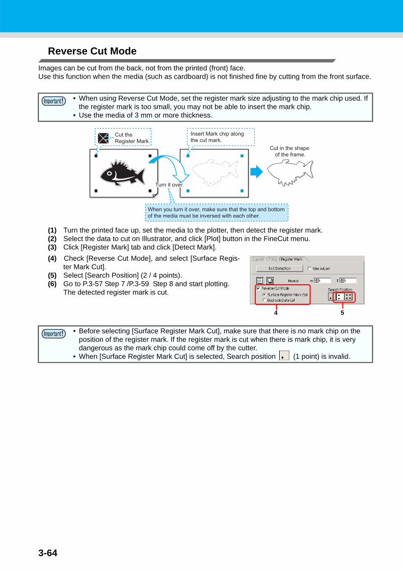
Reverse Cut ModeImages can be cut from the back, not from the printed (front) face.Use this function when the media (such as cardboard) is not finished fine by cutting from the front surface.
(1) Turn the printed face up, set the media to the plotter, then detect the register mark.(2) Select the data to cut on Illustrator, and click [Plot] button in the FineCut menu.(3) Click [Register Mark] tab and click [Detect Mark].(4) Check [Reverse Cut Mode], and select [Surface Regis-
ter Mark Cut].(5) Select [Search Position] (2 / 4 points).(6) Go to P.3-57 Step 7 /P.3-59 Step 8 and start plotting.
The detected register mark is cut.
• When using Reverse Cut Mode, set the register mark size adjusting to the mark chip used. If the register mark is too small, you may not be able to insert the mark chip.
• Use the media of 3 mm or more thickness.
• Before selecting [Surface Register Mark Cut], make sure that there is no mark chip on the position of the register mark. If the register mark is cut when there is mark chip, it is very dangerous as the mark chip could come off by the cutter.
• When [Surface Register Mark Cut] is selected, Search position (1 point) is invalid.
4 5

Make Stickers or Sign-panels
3-65
3
Advanced O
perations
(7) Turn back the media, and set it to the plotter.(8) Insert the mark chip using the cut mark.
Use the mark chip in place of the register mark.(9) Detect register mark with the plotter.
(10) Select [Backside Data Cut].The read data is displayed upside down.
(11) Select [Search Position] (1 / 2 / 4 points).(12) Go to P.3-57 Step 7 /P.3-59 Step 8 and start plotting.
10 11

3-66
Make Effective Use of SheetFor example, when cutting ABC with different colors each by color, if A and C are cut, the space of B becomes blank as B has different color. Move the cutting object to the blank part to cut without wasting blank.
1 Select an object on Illustrator.
2 Click [Plot] button in the FineCut menu.
3 Select an object to move using the Direct selection tool.
Select “A” for the example shown on the right.

Make Effective Use of Sheet
3-67
3
Advanced O
perations
4 Drag the selected object to the desired position.
To replace the object to the original position, click Original Layout button.
Drag
3-68
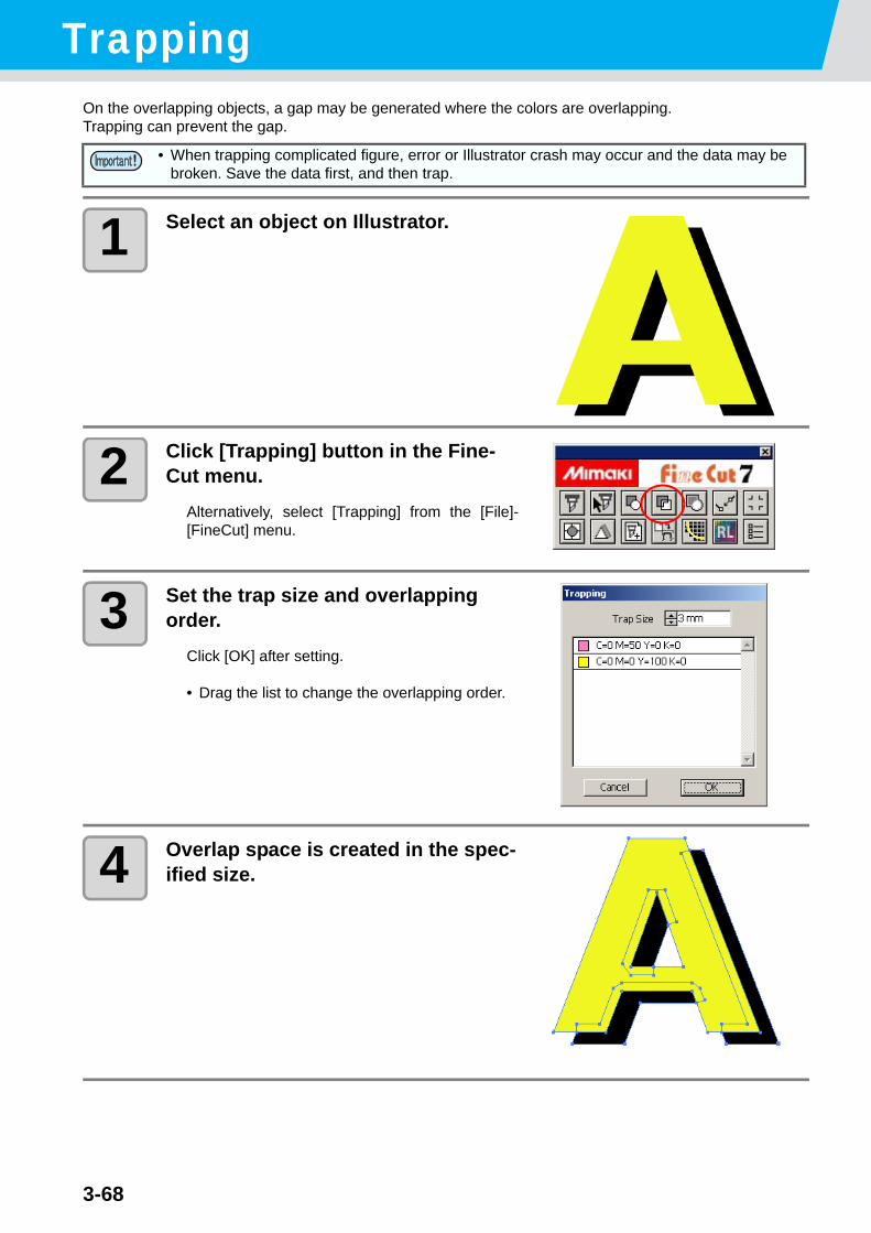
TrappingOn the overlapping objects, a gap may be generated where the colors are overlapping.Trapping can prevent the gap.
1 Select an object on Illustrator.
2 Click [Trapping] button in the Fine-Cut menu.
Alternatively, select [Trapping] from the [File]-[FineCut] menu.
3 Set the trap size and overlapping order.
Click [OK] after setting.
• Drag the list to change the overlapping order.
4 Overlap space is created in the spec-ified size.
• When trapping complicated figure, error or Illustrator crash may occur and the data may be broken. Save the data first, and then trap.
3-69
3
Advanced O
perationsRecognize Stroke Weight and Overlap
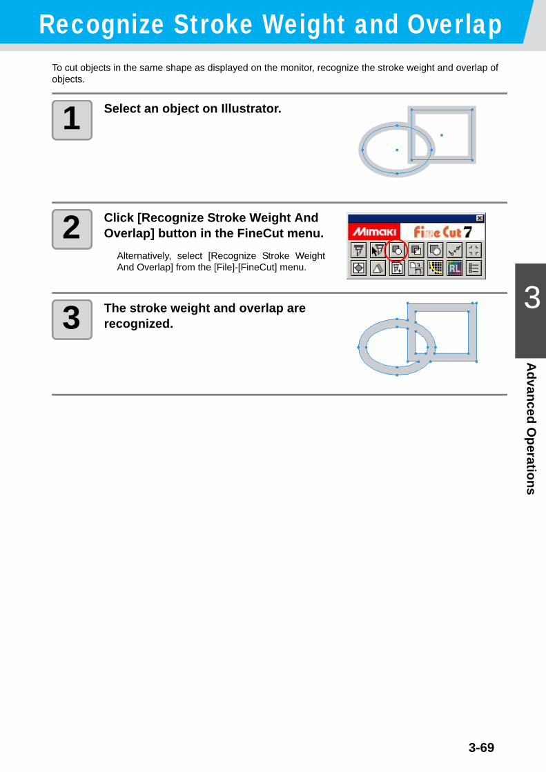
To cut objects in the same shape as displayed on the monitor, recognize the stroke weight and overlap of objects.
1 Select an object on Illustrator.
2 Click [Recognize Stroke Weight And Overlap] button in the FineCut menu.
Alternatively, select [Recognize Stroke WeightAnd Overlap] from the [File]-[FineCut] menu.
3 The stroke weight and overlap are recognized.

3-70
Import / Output Plot FileImport Plot File
Plot files created with cutting software can be imported to Illustrator.You can edit the imported plot files on Illustrator and plot them from FineCut.
1 Click [Import Plot File...] button in the FineCut menu.
Alternatively, select [Import Plot File...] from the[File]-[FineCut] menu.
2 Select a file to import, and click [Open].
3 Select the step size for the file to import.
Click [OK] after selecting.
4 The imported file is dis-played.
• The plot commands that can be imported are MGL-IC, MGL-IIC, and HP-GL.
• The image may be rotated and displayed depending on the application that the plot file is cre-ated.

Import / Output Plot File
3-71
3
Advanced O
perations
Output Plot FilePlot files created with cutting software can be output to the plotter.
1 Click [Output Plot File] button in the FineCut menu.
Alternatively, select [Output Plot File] from the[File]-[FineCut] menu.
2 Select a file to plot, and click [Open].
3-72
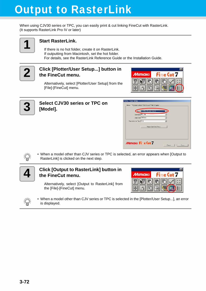
Output to RasterLinkWhen using CJV30 series or TPC, you can easily print & cut linking FineCut with RasterLink. (It supports RasterLink Pro IV or later)
1 Start RasterLink.If there is no hot folder, create it on RasterLink.If outputting from Macintosh, set the hot folder.For details, see the RasterLink Reference Guide or the Installation Guide.
2 Click [Plotter/User Setup...] button in the FineCut menu.
Alternatively, select [Plotter/User Setup] from the[File]-[FineCut] menu.
3 Select CJV30 series or TPC on [Model].
4 Click [Output to RasterLink] button in the FineCut menu.
Alternatively, select [Output to RasterLink] fromthe [File]-[FineCut] menu.
• When a model other than CJV series or TPC is selected, an error appears when [Output to RasterLink] is clicked on the next step.
• When a model other than CJV series or TPC is selected in the [Plotter/User Setup...], an error is displayed.

3-73
Output to RasterLink
3
Advanced O
perations
5 On Output to RasterLink screen, click [Select Hot Folder...].
Select the hot folder of RasterLink.If there is no hot folder, create it onRasterLink.
6 Select and set the layers to print or cut.
• The folder created from the [Create a new folder] button of the folder reference screen does not work as hot folder. Create hot folder on RasterLink.
Item Descriptiona Printer icon Click to put a mark on the printing layer.b Cutting icon Click to put a mark on the cutting layer.c Setting by layer Click button and select [Specify the Cut Condition on Each
Layer] or [Specify The Tool On Each Layer].Then, select the cutting condition or tools on the right column ofthe layer names.
• When both the print and the cut are marked on the Layer screen shown above, the plotter prints, and then cuts the object. If the printing layer has a register mark created with the register mark creation of FineCut, it reads the register mark position after printing, and cuts on the more accurate position.
• When only cutting is marked on the layer screen, include the register mark in the cutting layer to cut with the register mark loaded.
• If not setting [Specify the Cut Condition on Each Layer] or [Specify The Tool On Each Layer], it plots with the setting of the plotter.
• Data is placed with the margin of 0.5mm around.
• When cutting with the register mark loaded, set [1Pt] on [MARK DETECT] of CJV30 or TPC as the number of register mark detection. ( P.3-44 )
• When creating the register mark on the register mark creation of FineCut, uncheck [Leave a rectangle as the cutting line]. If checked, the plotter cuts with a part of the rectangle missed.( P.3-38 )
• When printing type2 register mark ( ), space between copies for at least register mark size. ( P.3-38 )
• Create only one set of register mark on Illustrator. Creating plural marks causes error.• When different settings are made for each layer, RasterLinkProIV Ver.1.1 or before cuts with
the condition shown on the top of the set layer list.RasterLinkProV or later will cut with each layer setting.
a b c

Output to RasterLink
3-74
7 Set the other items. ( P.4-29 )
8 Click [Output], then set EPS.Click [OK] to send the data to RasterLink.
EPS setting varies from the Illustrator version used.The display shown on the right is for Illustrator 10.
9 Execute printing & cutting on RasterLink.For details, see the RasterLink Reference Guide.
• For the Format of the Preview, select [None]. If the item other than [None] is selected, an error may occur.
• For Illustrator CS, a message below appears after clicking [OK] button.Since it is no problem, select [Yes].

3-75
3
Advanced O
perationsJoin paths
Joins corner points of an open path (the start and the end point is not connected).When reading DXF data into Illustrator, some paths that look connected are separated into several lines. If cutting this, pen-up occurs on every line. With CF3 (milling), it cannot cut considering the endmill diameter.Joining paths solves these problems.
1 Select the all paths to be joined on Illustrator.
2 Click [Join Path] button in the FineCut menu.
Alternatively, select [Join Path] from the [File]-[FineCut] menu.
3 Set the distance between corner points to be joined.
Click [OK] after setting.
4 The paths are joined.
• When the distance between corner points is longer than the set value, it is not joined.Checking the paths on Illustrator, set the value to join the paths.

3-76

This section describes the functions of FineCut.
Fill and Stroke of an Object .............. 4-2FineCut Menu ................................... 4-3
How to Display FineCut Menu ............4-3Menu ..................................................4-4
Plotter/User Setup ............................ 4-5Plotter .................................................4-5Output Condition Setup ......................4-6Communication ................................4-12Plot Dialog ........................................4-13Alert Display .....................................4-14
Plot Screen ..................................... 4-15
Plot Out Screen .............................. 4-24Outline Extraction Screen............... 4-27Output to RasterLink Screen .......... 4-29Line Edit Tool Screen ..................... 4-32
CHAPTER 4Description of Functions
4-2
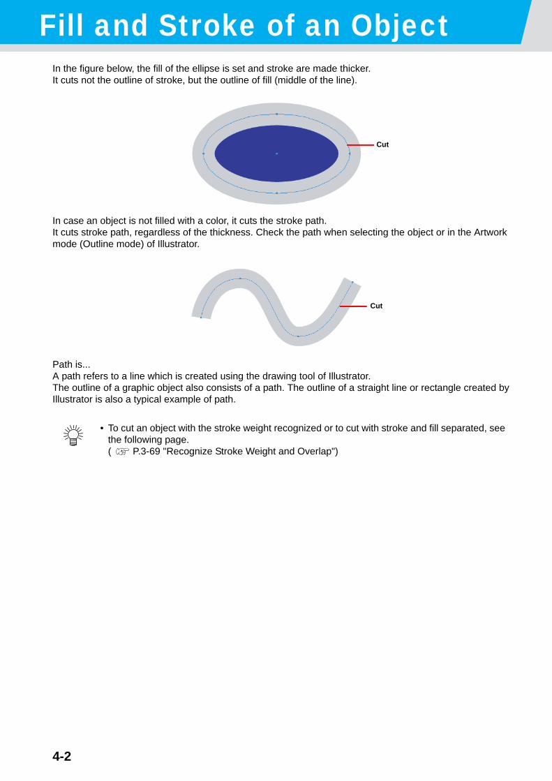
Fill and Stroke of an ObjectIn the figure below, the fill of the ellipse is set and stroke are made thicker.It cuts not the outline of stroke, but the outline of fill (middle of the line).
In case an object is not filled with a color, it cuts the stroke path.It cuts stroke path, regardless of the thickness. Check the path when selecting the object or in the Artwork mode (Outline mode) of Illustrator.
Path is...A path refers to a line which is created using the drawing tool of Illustrator.The outline of a graphic object also consists of a path. The outline of a straight line or rectangle created by Illustrator is also a typical example of path.
• To cut an object with the stroke weight recognized or to cut with stroke and fill separated, see the following page.( P.3-69 "Recognize Stroke Weight and Overlap")
Cut
Cut

4-3
4
Description of Functions
FineCut MenuHow to Display FineCut Menu
Display and select the FineCut menu from the following menus on Illustrator.
From [Window] menu of IllustratorClick [Show FineCut menu] to display the screen below.Click the button on the screen to start each menu.
From [File] menu of IllustratorClick [FineCut] and click each menu.

FineCut Menu
4-4
Menu
Button Menu Description
Plot Sets the layout or options of object to plot. ( P.4-15)
Plot Selected Path Plots only the selected object.
Recognize Stroke Weight and Overlap
Recognizes the stroke weight and overlap of the selected object. ( P.3-69)
Trapping Traps the selected object. ( P.3-68)
Frame Extraction Creates a frame for the selected object. ( P.3-36)
Join Path Joins corner points of open path (the start and the end point is notconnected). ( P.3-75)
Register Mark Cre-ation
Creates a register mark. ( P.3-38 for CG/CJV30/TPC series,P.3-40 for CF2/DC/CF3 series)
Create Weed Line Creates a precut line (weed line) around the object to tear off thesticker with ease. ( P.3-16)
Remove Weed Line(in the File menu only) Removes the created weed line.
Create Shadow/Edge Creates a shadow /edge on the object. ( P.3-10)
Remove Shadow/Edge(in the File menu only)
Removes the created shadow /edge on the object.
Output Plot File... Outputs created plot file to the plotter. ( P.3-71)
Import Plot File... Imports saved plot file. ( P.3-70)
Outline Tool Creates the outline to cut a bitmap image. ( P.3-12)
Output to RasterLink Sends the set file to RasterLink when using CJV30/ TPC series. ( P.3-72)
Plotter/User Setup Sets the plotter used, communication condition to the plotter orothers. ( P.4-5)

4-5
4
Description of Functions
Plotter/User SetupSet the model or communication conditions to enable communication between FineCut and the plotter.Click [Plotter/User Setup] button in the FineCut menu.
PlotterSet the plotter connected. Refer to the operation manual of the plotter for details.
• If the settings set in this screen differs from the settings on the plotter, it cannot output objects normally. Be sure to set the same values as the plotter settings.
Item DescriptionModel Select the plotter model connected.
Command Select the command set on the plotter.Step Size Select the step size set on the plotter.
Approximation Type Select the approximation type when cutting bezier curve of theobject.
Output Condition Setup... Set media or tools. ( next page)
• If you changed [Approximation Type], adjust the cut conditions again.An excessive pressure by some media could damage the cutter.
• When [CF3 (Milling)] is selected on [Model], you can select [Spline] only on [Approximation Type].

4-6
Output Condition Setup
Common to all models
• When CF3/CJV30/TPC series is selected, [Default Setup] is not displayed.
Item Description1 Media Name Displays created media names (output condition).2 Add Add the media name.3 Edit Change the media name. Select media from [Media Name], and
click [Edit].4 Delete Delete the media name. Select media from [Media Name], and
click [Delete].5 Copy Copy the media name. Select media from [Media Name], and click
[Copy].6 Sort Sort the media name in ascending order.7 Import Import saved media name (output condition) files.
To plot with the same condition in different environment, click[Import] and load the saved file.
8 Export Save the all media names (output condition) to a file.9 Default Setup When output condition is set by color/layer ( P.3-26), set output
conditions (Tool/ Speed/ Press/ Offset) for frame or mark thatcannot be set by color/ layer.
10 Condition Display /change the output condition. Select media from [MediaName] to display the output condition. Displayed items variesdepending on the selected model. ( next page)
23456
78
9
10
1
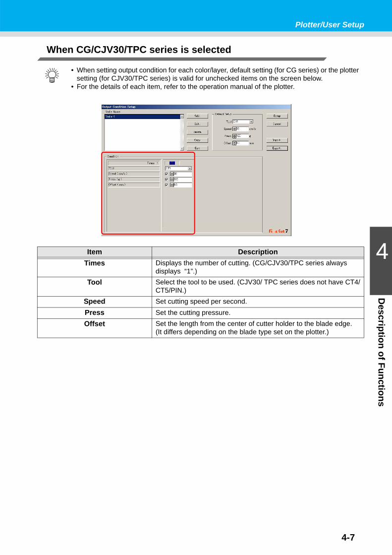
4-7
Plotter/User Setup
4
Description of Functions
When CG/CJV30/TPC series is selected
• When setting output condition for each color/layer, default setting (for CG series) or the plotter setting (for CJV30/TPC series) is valid for unchecked items on the screen below.
• For the details of each item, refer to the operation manual of the plotter.
Item DescriptionTimes Displays the number of cutting. (CG/CJV30/TPC series always
displays “1”.)Tool Select the tool to be used. (CJV30/ TPC series does not have CT4/
CT5/PIN.)Speed Set cutting speed per second.Press Set the cutting pressure.Offset Set the length from the center of cutter holder to the blade edge.
(It differs depending on the blade type set on the plotter.)

4-8
When CF/CF2/DC/CF3 (except milling) is selected
• When setting output condition for each color/layer, default setting (for CF/CF2/DC series) or the plotter setting (for CF3 (except milling) series) is valid for unchecked items on the screen below.
• For the details of each item, refer to the operation manual of the plotter.
Item DescriptionTimes Display or set the number of cutting.
To cut hard or thick media, set cutting times/speed/pressure multi-ple times for a single cut line.Click to increase the number of cutting. Set the output conditionfor each cutting. Click to decrease the number of cutting.
Tool Select the tool to be used. Select the tool number or the tool nameset on the plotter.
• If the unset tool is selected, an error displays on the plotter. Select the correct tool.
Speed Set cutting speed per second.Press Set the pressure to cut.Offset Set the length from the center of cutter holder to the blade edge.
Arc Theta Correct Adjust the misalignment of origin /end point of the cutting arc.
Move to previous / next page. It displays when the number ofcutting is more than 4 times.
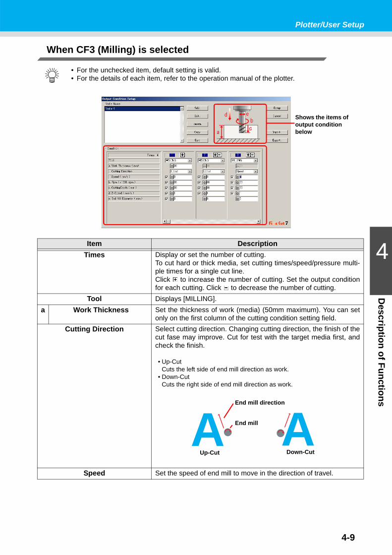
4-9
Plotter/User Setup
4
Description of Functions
When CF3 (Milling) is selected
• For the unchecked item, default setting is valid.• For the details of each item, refer to the operation manual of the plotter.
Item DescriptionTimes Display or set the number of cutting.
To cut hard or thick media, set cutting times/speed/pressure multi-ple times for a single cut line.Click to increase the number of cutting. Set the output conditionfor each cutting. Click to decrease the number of cutting.
Tool Displays [MILLING].a Work Thickness Set the thickness of work (media) (50mm maximum). You can set
only on the first column of the cutting condition setting field.Cutting Direction Select cutting direction. Changing cutting direction, the finish of the
cut fase may improve. Cut for test with the target media first, andcheck the finish.
• Up-CutCuts the left side of end mill direction as work.
• Down-CutCuts the right side of end mill direction as work.
Speed Set the speed of end mill to move in the direction of travel.
Shows the items of output condition below
A AAEnd mill direction
End mill
Up-Cut Down-Cut
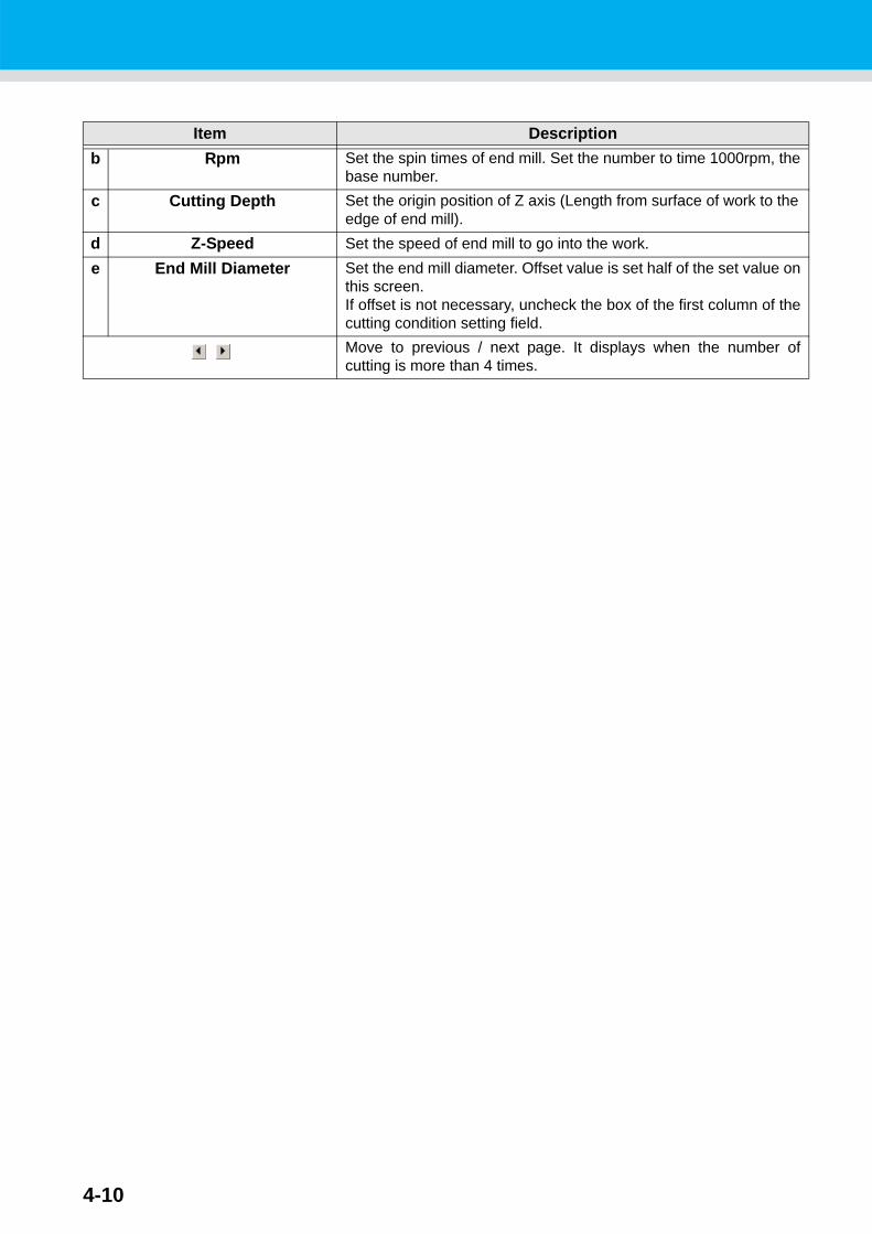
4-10
Item Descriptionb Rpm Set the spin times of end mill. Set the number to time 1000rpm, the
base number.c Cutting Depth Set the origin position of Z axis (Length from surface of work to the
edge of end mill).d Z-Speed Set the speed of end mill to go into the work.e End Mill Diameter Set the end mill diameter. Offset value is set half of the set value on
this screen.If offset is not necessary, uncheck the box of the first column of thecutting condition setting field.
Move to previous / next page. It displays when the number ofcutting is more than 4 times.

4-11
Plotter/User Setup
4
Description of Functions
OffsetWhen CF3 (Milling) is selected and [End Mill Diameter] is set , the object is offset and cut as follows depending on the object on Illustrator and the setting of FineCut.
• If paths are crossed, periphery is offset.• The path in the crossed path is not cut.
• If offset objects are touched each other, the objects are united.
• If copy function is used, set [Copy Margin] wide (more than 10mm), not to go one object over the nextobject.
• If one part goes over the other part when offsetting inward, the part over the other part is not cut.
• Open path is not offset.
• If output condition is set on each color /layer, each color /layer is offset.
ABC ABC ABC ABC

4-12
CommunicationSet communication conditions for the plotter connected.
Item DescriptionPort Select a port connected to the plotter.
When using CG-FX / CG-75ML / CG-60SR / CG-SRII / CJV30 /TPC / CF3 series, you can select USB connection.Connect computer to the plotter and turn the power ON.Then select [USB] on this screen, and select the name ofconnected device.
Baud Rate (When [Serial] is selected on [Port])Select the transfer rate.
Data Length (When [Serial] is selected on [Port])Select the number of data bits.
Parity (When [Serial] is selected on [Port])Select the parity check method.
Handshake (When [Serial] is selected on [Port])Select the handshake method.

4-13
Plotter/User Setup
4
Description of Functions
Plot DialogSet the display of Plot screen and Output to RasterLink screen.
Item DescriptionDefault Sheet Size If the sheet is not loaded properly, or [Loading Sheet When Dialog
Displays] is unchecked, the preview screen is displayed with thesize set here.
Display Type Select the display type of Plot screen or Output to RasterLinkscreen.
Loading Sheet When Dialog Dis-plays
The sheet size is automatically loaded and previewed on Plotscreen.
Plot Only Viewable Paths Plots only displayed paths. Undisplayed paths are not plotted.
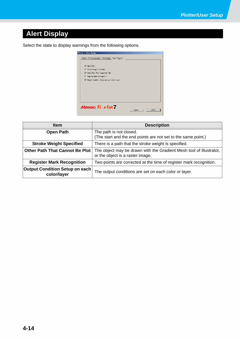
Plotter/User Setup
4-14
Alert DisplaySelect the state to display warnings from the following options.
Item DescriptionOpen Path The path is not closed.
(The start and the end points are not set to the same point.)Stroke Weight Specified There is a path that the stroke weight is specified.
Other Path That Cannot Be Plot The object may be drawn with the Gradient Mesh tool of Illustrator,or the object is a raster image.
Register Mark Recognition Two-points are corrected at the time of register mark recognition.Output Condition Setup on each
color/layer The output conditions are set on each color or layer.

4-15
4
Description of Functions
Plot ScreenSet for plotting.To display this screen, click [Plot] button in the FineCut menu.
1 Tool BoxMove or enlarge/reduce the object.
2 Screen Display ModeClick the tab to switch the display mode.
Button Item DescriptionSelection Tool Move a whole object displayed.
Or move the division line of tiling.
Direct Selection Tool
Select and move the part of an object. Moving the object to a blank position of the sheet, you can usesheet without waste. ( P.3-66)
Move Preview Area Tool Change the object display area.
Zoom Tool Enlarge or reduce the layout area.Click on the cutting area (white area) to enlarge the view. Toreduce the view, click on the layout area as pressing down the [Alt]key (Windows) or [Option] key (Macintosh).
Item DescriptionPreview Mode Displays the object with colors.Cutline Mode Displays the object with paths (outline).
It is effective to confirm a white object or cutting-line.
1
2
3
4
5
6
10
7 8 9
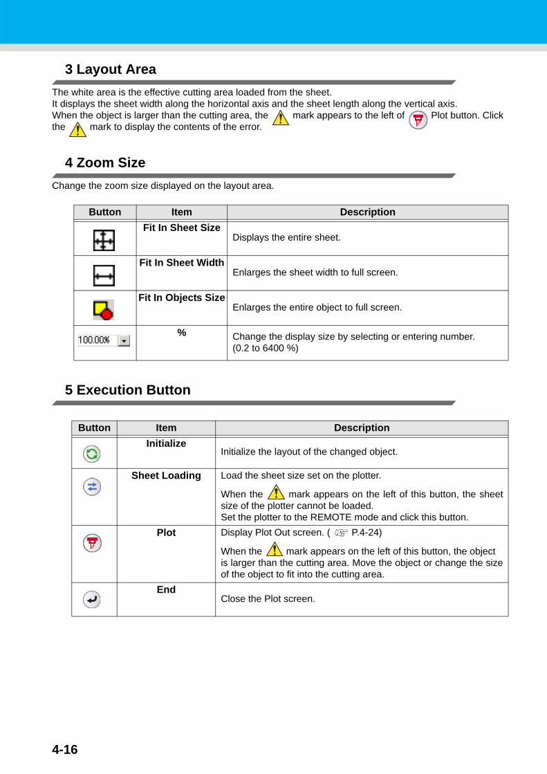
4-16
3 Layout AreaThe white area is the effective cutting area loaded from the sheet. It displays the sheet width along the horizontal axis and the sheet length along the vertical axis.When the object is larger than the cutting area, the mark appears to the left of Plot button. Click the mark to display the contents of the error.
4 Zoom SizeChange the zoom size displayed on the layout area.
5 Execution Button
Button Item DescriptionFit In Sheet Size
Displays the entire sheet.
Fit In Sheet WidthEnlarges the sheet width to full screen.
Fit In Objects SizeEnlarges the entire object to full screen.
% Change the display size by selecting or entering number.(0.2 to 6400 %)
Button Item DescriptionInitialize
Initialize the layout of the changed object.
Sheet Loading Load the sheet size set on the plotter.
When the mark appears on the left of this button, the sheetsize of the plotter cannot be loaded.Set the plotter to the REMOTE mode and click this button.
Plot Display Plot Out screen. ( P.4-24)
When the mark appears on the left of this button, the objectis larger than the cutting area. Move the object or change the sizeof the object to fit into the cutting area.
EndClose the Plot screen.

4-17
Plot Screen
4
Description of Functions
6 Size input area
Item DescriptionSheet Size
Click Sheet loading button to display the loaded sheet size.Alternatively, enter the sheet size (width and length of the cuttingarea).
• When [CF3 (Milling)] is selected on [Model] in Plotter/User Setup screen ( P.4-5), Fine-Cut reduces the width and length to cut 5 mm smaller than the cutting origin of the plotter, considering the end mill diameter of the milling. Therefore, the width and length displayed on [Sheet size] are 10 mm smaller than the plotter setting.
Total Length
5mm
5mm
5mm
5mm Effective area of plotter
Sheet area of FineCut
Origin of FineCut
Cutting origin of plotter
End mill track

4-18
Item DescriptionOffset Change the origin position.
The origin is set at the bottom right corner (CG/CJV30/TPC/CF3series) or the bottom left corner (CF/CF2/DC series) of the layoutarea. The default origin is at 0 mm (both vertically and horizontally)of the layout area.
Size Change the vertical and horizontal lengths of an object.When the “ - “ mark is shown between [vertical] and [horizontal]length column, the aspect ratio is retained after changing eitherlength.To change the vertical and horizontal lengths separately, check the[Unlock Scale] on the [Layout] screen below.
Scale ( P.3-2) Set the magnification of the vertical and horizontal lengths.When the “ - “ mark is shown between [vertical] and [horizontal]column, the aspect ratio is retained after changing either value. To change the vertical and horizontal magnification separately,check the [Unlock Scale].
Copy ( P.3-6) Enter the number of copies along the vertical and horizontal direc-tions.
Copy Margin ( P.3-6) Set the margin between objects along the vertical and horizontaldirections.
Frame Make and cut a frame around the target object. In addition, set thedistance between the object and the frame. It enables to peel theunnecessary part of the sticker easily.• With the center mark and corner mark ( P.3-5), you can easily align
and affix a cut sticker.
Total Length Displays the width and the height of an object.When multiple numbers are entered on [Copy], it displays with the length of all copies. If margin or frame is set, those lengthsare also included.
CG/CJV30/TPC/CF3 series CF/CF2/DC series

4-19
Plot Screen
4
Description of Functions
7 Layout
Button Item DescriptionTurn Rotate the object clockwise in unit of 90 degrees. Degrees (0, 90,
180, 270) are displayed in the arrow mark.
MoveClick the desired direction of arrow to move the object.
FitFit the object to the sheet size.
Original Layout Reset to the original layout that is changed by Direct selectiontool.
Mirror Reverse the object in mirror image and cut it.
Unlock Scale ( P.3-2) When changing the size of the object, change the aspect ratio.
Origin Lock ( P.3-18) Fix the object position on the object created place.If unlocked, it cuts on the bottom right or the bottom left of thesheet. When cutting specified color or layer only, you can usesheet without waste.
Center Mark ( P.3-5) When setting [frame] on the size input area, put marks in the cen-ter of the frame in every direction.You can affix a cut sticker on the desired position with the marks.
Corner Mark ( P.3-5) When setting [frame] on the size input area, put marks on all cor-ners of the frame.You can affix a cut sticker in a horizontal position with the marks.
Unit Set the display unit in the Plot screen.Select from cm, mm, inch, or pt.
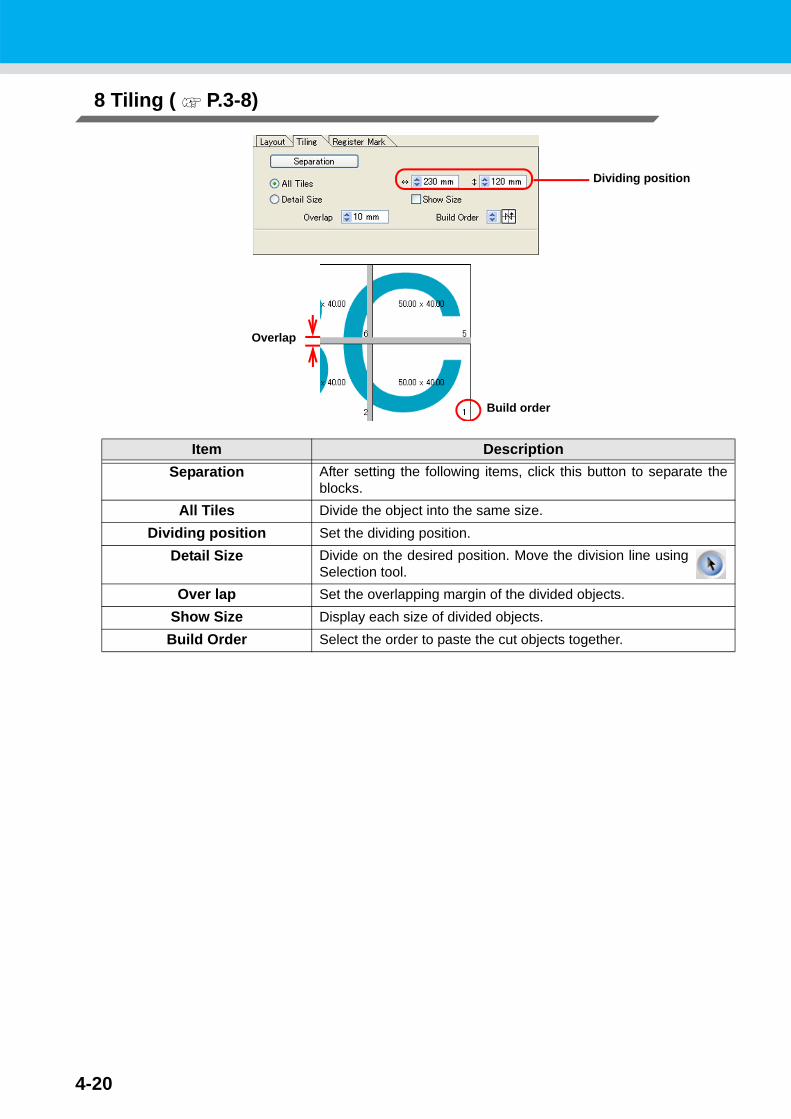
4-20
8 Tiling ( P.3-8)
Item DescriptionSeparation After setting the following items, click this button to separate the
blocks.All Tiles Divide the object into the same size.
Dividing position Set the dividing position.Detail Size Divide on the desired position. Move the division line using
Selection tool.Over lap Set the overlapping margin of the divided objects.
Show Size Display each size of divided objects.Build Order Select the order to paste the cut objects together.
Dividing position
Build order
Overlap

4-21
Plot Screen
4
Description of Functions
Layout of divided tilesClick [Separation] to display the setting screen.
Item DescriptionCancel Cancel the division.
Turn Rotate the divided objects.Move Move divided objects within the sheet.Mark
(Except CF3 (Milling))Mark the divided objects.Select or input the mark size on the size column.Paste the divided objects together on the marks.
Tiles Space When cutting continuously, set the space between divided objects.
Mark
Tile space

4-22
Register MarkThis function is effective only when [“model name” (with mark sensor)] is selected in the [Model] of [Plotter/User Setup] screen.
CG-EX / FX / 75ML / 60SR / SRII, CJV30 / TPCseries
CF2 / DC / CF3 series
Item Descriptiona [Detect Mark]/[Exit Detection]
buttonCorrect the angle and the size of the detected register mark.Click [Exit Detection] to cancel the detection.
b Setting of continuous cutting Select the roll sheet (multi-mode) or the leaf sheet (single mode),and set the number of continuous cutting. ( P.3-62)
c Search Position Select the search position of the register mark. For CG/CJV30series or TPC, select the first detecting position on upper boxes,and select the second or subsequent detecting position on lowerboxes.
d ID Certification Mode Check this when cutting with ID certification mode by CG-75ML.( P.3-50)
e Reverse Cut Mode (except CF3 (Milling)) Cut from the back, not from the printed face . ( P.3-64)
f Size Adjust When the size of the actual data and the printed media aredifferent, cut the frame aligning with the printed media.( P.3-63)
Mark Separation( P.3-63)
When [mark separation] is executed, the following screen appears.Select cut area No. and search the position to cut.
ad
b
c
a
f
b
c
e
Select Cut Area No.
Select Search Position
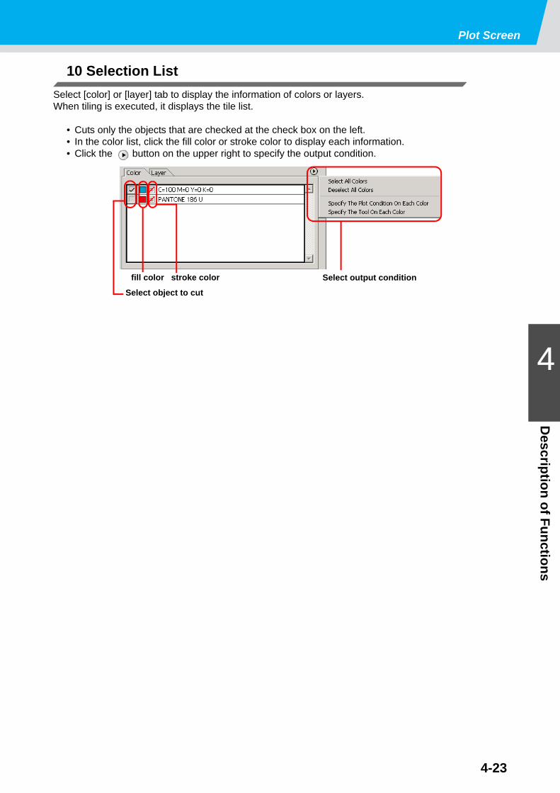
Plot Screen
4-23
4
Description of Functions
10 Selection List Select [color] or [layer] tab to display the information of colors or layers.When tiling is executed, it displays the tile list.
• Cuts only the objects that are checked at the check box on the left.• In the color list, click the fill color or stroke color to display each information.• Click the button on the upper right to specify the output condition.
Select output conditionfill color stroke color
Select object to cut

4-24
Plot Out ScreenSet for outputTo display this screen, click Plot button in the Plot screen.
1 Plot ConditionSelect the output condition.
• In the case of specifying output conditions or tools on each color or layer, you cannot edit on this screen. Instead, click button on the right of color/layer tab in Plot screen and select [Edit Plot Condition...].
Item DescriptionPlotter Condition
(except CF3 (Milling)) Plot with the output condition set on the plotter.
Select Condition Select the plot condition set on FineCut.Click [Edit] button to add media, or to set cutting conditions bymedia types. ( P.4-6)
Custom(except CF3 (Milling))
Set plot condition on this screen.Refer to the following page for details. ( P.4-6 "Output Condition Setup")
1
2
3
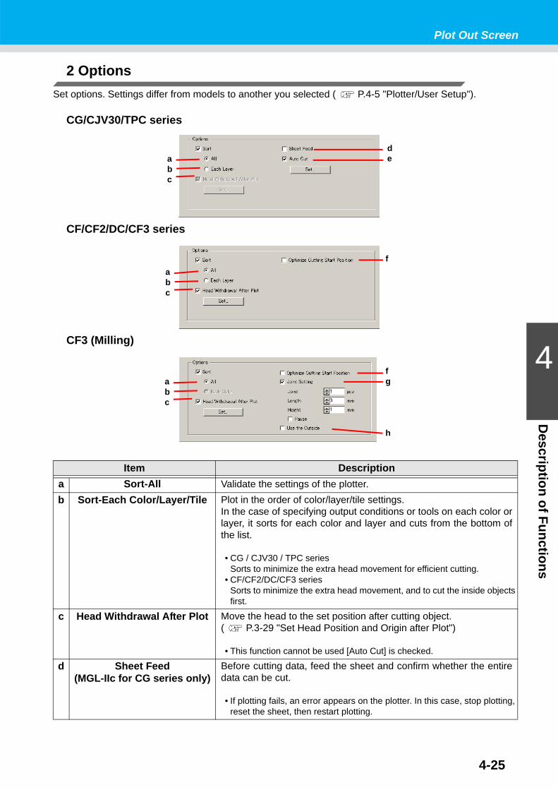
4-25
Plot Out Screen
4
Description of Functions
2 OptionsSet options. Settings differ from models to another you selected ( P.4-5 "Plotter/User Setup").
CG/CJV30/TPC series
CF/CF2/DC/CF3 series
CF3 (Milling)
Item Descriptiona Sort-All Validate the settings of the plotter.b Sort-Each Color/Layer/Tile Plot in the order of color/layer/tile settings.
In the case of specifying output conditions or tools on each color orlayer, it sorts for each color and layer and cuts from the bottom ofthe list.
• CG / CJV30 / TPC seriesSorts to minimize the extra head movement for efficient cutting.
• CF/CF2/DC/CF3 seriesSorts to minimize the extra head movement, and to cut the inside objects first.
c Head Withdrawal After Plot Move the head to the set position after cutting object.( P.3-29 "Set Head Position and Origin after Plot")
• This function cannot be used [Auto Cut] is checked.
d Sheet Feed (MGL-IIc for CG series only)
Before cutting data, feed the sheet and confirm whether the entiredata can be cut.
• If plotting fails, an error appears on the plotter. In this case, stop plotting, reset the sheet, then restart plotting.
dea
bc
fabc
fg
h
abc

Plot Out Screen
4-26
3 Buttons
Item Descriptione Auto Cut
(CG-FX series / CG-75ML / CJV30 series / TPC only)
When cutting roll sheet continuously, it cuts off the sheet automatically after cutting.( P.3-46 "In case of Auto Cut").
f Optimize Cutting Start Posi-tion
Optimizes the start position of cutting to finish finely.If unchecked, cutting starts from the position that the data started todraw.• When CF3 (milling) is used, be sure to check the start position of cutting
by preview after setting.• With optimizing, the start position might be placed out of the object. If the
cutting line goes over the next object, space among objects on Illustrator.
g Joint Setting Leaves a part of the cutting line, and cuts it last. It prevents thework from misaligning and makes the cutting surface fine.[Joint]: Set the number of joint (places to leave).[Length/ Height]: Set the length and height to leave.[Pause]: Select to withdraw the head and to fix the media with tape.
h Use the Outside Cuts out inside of the object to use the outside. If checked, offsetdirection and cutting direction are optimized.
Item DescriptionPlot Starts plotting as the set conditions.
Cancel Cancels plotting.Preview Previews the plotting with the set condition.
Confirm the plotting by preview and adjust the settings.( P.3-31 "Check the Cutting Process by Preview" )
• Before starting plotting, be sure to check the cutline by preview.
Save as file Save the plot data in a plot file.Select the folder and click [Save].
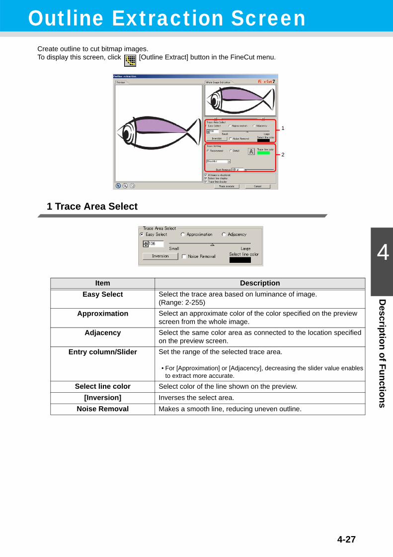
4-27
4
Description of Functions
Outline Extraction ScreenCreate outline to cut bitmap images.To display this screen, click [Outline Extract] button in the FineCut menu.
1 Trace Area Select
Item DescriptionEasy Select Select the trace area based on luminance of image.
(Range: 2-255)Approximation Select an approximate color of the color specified on the preview
screen from the whole image.Adjacency Select the same color area as connected to the location specified
on the preview screen.Entry column/Slider Set the range of the selected trace area.
• For [Approximation] or [Adjacency], decreasing the slider value enables to extract more accurate.
Select line color Select color of the line shown on the preview.[Inversion] Inverses the select area.
Noise Removal Makes a smooth line, reducing uneven outline.
1
2

Outline Extraction Screen
4-28
2 Trace Setting
Recommended setting
Detail setting
Common setting
Item DescriptionBeautiful Creates detail outlines.Fast Extracting time is fast but the details of the outline is rough.
Item DescriptionLine length Specify a length for one line. The shorter the line becomes, the
more elaborate in detail.Angle Specify an angle for the top shape of line. The angle increases
by angle becoming small, and the curvilinear increases by anglebecoming large.
Item Description
Extracts only the outline.
Trace line color Select trace line color displaying on the preview.Dust Removal Delete the line that is shorter part than the specified length.
Remove the extra lines created by scanning.Image display Displays the image to be traced. You can confirm the outlines to
be extracted or compare the image and the traced image.Select line display Displays the selected line area to be traced.Trace line display Displays the traced line.
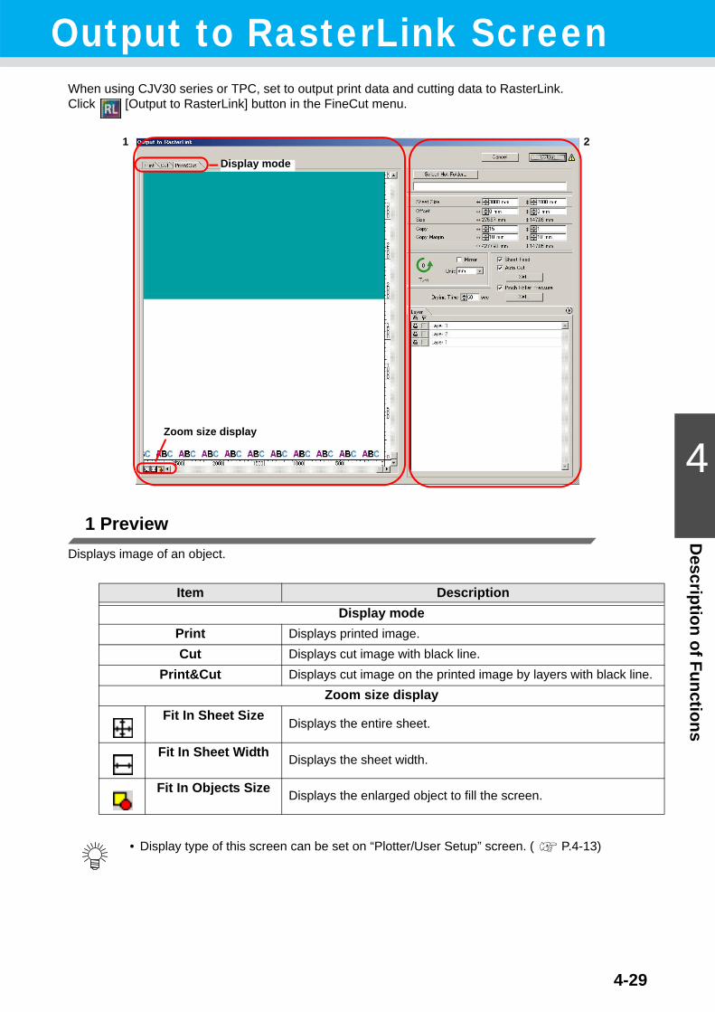
4-29
4
Description of Functions
Output to RasterLink ScreenWhen using CJV30 series or TPC, set to output print data and cutting data to RasterLink.Click [Output to RasterLink] button in the FineCut menu.
1 PreviewDisplays image of an object.
Item DescriptionDisplay mode
Print Displays printed image.Cut Displays cut image with black line.
Print&Cut Displays cut image on the printed image by layers with black line.Zoom size display
Fit In Sheet Size Displays the entire sheet.
Fit In Sheet Width Displays the sheet width.
Fit In Objects Size Displays the enlarged object to fill the screen.
• Display type of this screen can be set on “Plotter/User Setup” screen. ( P.4-13)
1
Display mode
Zoom size display
2

4-30
2 Setting
Item DescriptionCancel Cancel the setting.Output Set EPS and output a data to RasterLink.
markAppears if an image gets out of the sheet by the object size or thecopy setting.
Select Hot Folder... Select the hot folder of RasterLink.
• The folder created from the [Create a new folder] button of the folder reference screen does not work as hot folder. Create hot folder from RasterLink.
Sheet Size Enter an effective sheet size (width and length) set on the plotter.Effective size can be checked on RasterLink.
Offset Set an offset (horizontal/ vertical direction) from the origin on thelower right of the sheet.
Size Displays the object width.Copy Enter the number of copies of one object along the horizontal/ ver-
tical direction.Copy Margin Enter the margin between the copied objects along the horizontal/
vertical direction.Turn Click to turn the object by 90 degrees anticlockwise.
Mirror Reverses the right and left of the object image and cut it.Unit Set the display unit in this screen.
Sheet Feed Before plotting, feed the sheet to check whether the entire datacan be plotted.
Auto Cut When cutting a roll sheet continuously, cut off a sheet automati-cally after completing the plotting. [Set...] button becomes effectivewith this item checked.On the screen below, set the margin length from maximum datalength (the length from the final line to the cutting position) andcutting a data at every line.( P.3-46 "In case of Auto Cut")
Pinch Roller Pressure Set the pinch roller pressure. [Set...] button becomes effective withthis item checked.On the screen below, set the pinch roller pressure when printing orcutting (ends or inner position).

Output to RasterLink Screen
4-31
4
Description of Functions
Item DescriptionDrying Time Set a drying time of media after printing.
Layer Select/Set the layer to print or plot.
a Printer iconClick to put a mark on the printing layer.
b Cutting iconClick to put a mark on the cutting layer.
c Setting by layerClick button and select [Specify the Cut Condition on Each Layer] or [Specify The Tool On Each Layer].Then, select the cutting condition or tools on the right column of the layer names.
• When both the print and the cut are marked on the Layer screen shown above, the plotter prints, and then cuts the object. If the printing layer has a register mark created with the register mark creation of FineCut, it reads the register mark position after printing, and cuts on the more accurate position.
• When only cutting is marked on the layer screen, include the register mark in the cutting layer to cut with the register mark loaded.
• If not setting [Specify the Cut Condition on Each Layer] or [Specify The Tool On Each Layer], it plots with the setting of the plotter.
• Data is placed with the margin of 0.5mm around.
• When cutting with the register mark loaded, set [1Pt] on [MARK DETECT] of CJV30 or TPC as the number of register mark detection. ( P.3-44 )
• When creating the register mark on the register mark creation of FineCut, uncheck [Leave a rectangle as the cutting line]. If checked, the plotter cuts with a part of the rectangle missed.( P.3-38 )
• When printing type2 register mark ( ), space between copies for at least register mark size.
• Create only one set of register mark on Illustrator. Creating plural marks causes error.• When different settings are made for each layer, RasterLinkProIV Ver.1.1 or before cuts with
the condition shown on the top of the set layer list in the layer screen.RasterLinkProV or later will cut with each layer setting.
a b c
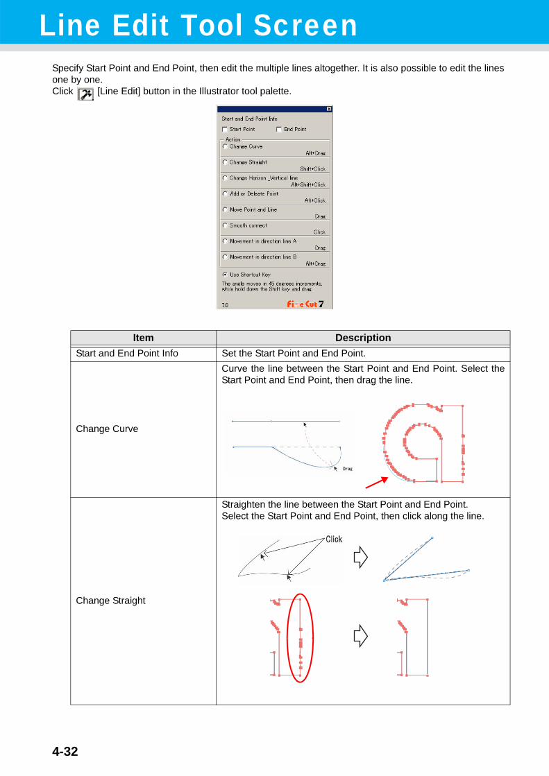
4-32
Line Edit Tool ScreenSpecify Start Point and End Point, then edit the multiple lines altogether. It is also possible to edit the lines one by one.Click [Line Edit] button in the Illustrator tool palette.
Item DescriptionStart and End Point Info Set the Start Point and End Point.
Change Curve
Curve the line between the Start Point and End Point. Select theStart Point and End Point, then drag the line.
Change Straight
Straighten the line between the Start Point and End Point.Select the Start Point and End Point, then click along the line.

4-33
Line Edit Tool Screen
4
Description of Functions
Item Description
Change Horizon_Vertical line
Click along the line to make it horizontal or vertical. The line canbe measured as horizontal or vertical by an angle of the clickedline.
Add or Delete Point To add an anchor point, click the position to add on the line. Todelete the anchor point, click the anchor point.
Move Point and Line Move the line while holding the shape between Start Point andEnd Point.
Smooth connect
Set the control point at identical tilt and smooth the joint of the line.

Line Edit Tool Screen
4-34
Item Description
Movement in direction line A
Move the control point to change the curvilinear shape. At a time,move the control point in opposite side to smooth the joint of theline.
Movement in direction line B
Move only the selected control point to change the curvilinearshape.

This section describes the troubles and the solutions.
Troubleshooting....................................................... 5-2Sheet size cannot be changed .......................................... 5-2Memory runs out................................................................ 5-2Communication port error or Error No.1 occurs................. 5-2Improperly plotted on the wrap-around text ....................... 5-3Invalid path created in the object when creating edge....... 5-3Shadow or edge cannot be deleted ................................... 5-3The inside path is not cut when cutting the path that is applied “Effect” of Illustrator with CF3 (Milling)............................... 5-3An error occurs during outputting to RasterLink ................ 5-3
CHAPTER 5Troubleshooting

5-2
TroubleshootingSheet size cannot be changed
When the MGL-IIc commands are usedThe sheet size does not change even if shifting the origin on the plotter and click Sheet Loading button.FineCut always display the sheet size set on the plotter. In this case, the data may be cut overflowed even if the data fits into the cutting area in the layout area.
When the MGL-Ic commands are usedFineCut displays the effective cutting area. Therefore, even if shifting the origin on the plotter, it can cut normally when the data fits into the cutting area.
Memory runs outStroke weight and overlap recognition/ Frame extraction/ Trapping/ Outline extraction requires large amount of memory for complicated objects. Depending on the specifications of the machine, the target object may not be processed for an insufficient memory.In this case, divide the object into several objects, and execute the process for each divided object, instead of selecting the entire object and executing the process at one time. Some types of object can avoid the insufficient memory error in this way.For Outline extraction, lowering the resolution to avoid insufficient memory error.
Example 1To recognize the stroke weight and overlap for a complicated object with the title and the object sepa-rated, select each component and execute the processing separately, instead of selecting the entire object. If some parts are overlaid, select only overlaid parts and execute the process.
Example 2To extract a complicated object with an outer frame, select only outer frame and execute the frame extraction. It enables to process rapidly without wasting memory.
Communication port error or Error No.1 occurs
When the following error messages appear as clicking Plot button, follow the direction below.
• For Windows, communication port error or Error No.1 may occur if using a driver software for thetablet, printer diver, or other peripheral devices which uses the serial port.In this case, change the setting to use the other port.
• For Macintosh, the plotter-connected port may have already been used by AppleTalk.In this case, disable AppleTalk from the selector, or select a plotter-unconnected port from theAppleTalk control panel document. When the plotter is connected to the printer port, select the modemport or Ethernet.
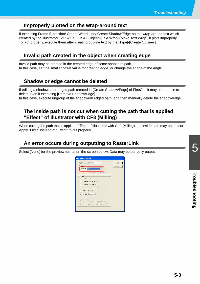
Troubleshooting
5-3
5
Troubleshooting
Improperly plotted on the wrap-around textIf executing Frame Extraction/ Create Weed Line/ Create Shadow/Edge on the wrap-around text which created by the IllustratorCS/CS2/CS3/CS4 -[Object]-[Text Wrap]-[Make Text Wrap], it plots improperly.To plot properly, execute them after creating out-line text by the [Type]-[Create Outlines].
Invalid path created in the object when creating edgeInvalid path may be created in the created edge of some shapes of path.In this case, set the smaller offset value for creating edge, or change the shape of the angle.
Shadow or edge cannot be deletedIf editing a shadowed or edged path created in [Create Shadow/Edge] of FineCut, it may not be able to delete even if executing [Remove Shadow/Edge].In this case, execute ungroup of the shadowed/ edged path, and then manually delete the shadow/edge.
The inside path is not cut when cutting the path that is applied “Effect” of Illustrator with CF3 (Milling)
When cutting the path that is applied “Effect” of Illustrator with CF3 (Milling), the inside path may not be cut. Apply “Filter” instead of “Effect” to cut properly.
An error occurs during outputting to RasterLinkSelect [None] for the preview format on the screen below. Data may be correctly output.

5-4

D201583-17-09012009

EMSW : 7.6
Printed in Japan© MIMAKI ENGINEERING CO., LTD.2009