operation and safety manual - arentis...3121644 – jlg lift – a foreword this manual is a very...
TRANSCRIPT

ANSI ®
Operation and Safety ManualOriginal Instructions - Keep this manual with the machine at all times.
Boom Lift ModelsE400A NarrowE400AJPE400AJP NarrowM400AJPM400AJP NarrowS/N 0300189901 to Present
3121644January 5, 2015


FOREWORD
a
s.
rs, and lessees with the precautions and operatingtended purpose.
the right to make specification changes without
3121644 – JLG Lift –
FOREWORD
This manual is a very important tool! Keep it with the machine at all time
The purpose of this manual is to provide owners, users, operators, lessoprocedures essential for the safe and proper machine operation for its in
Due to continuous product improvements, JLG Industries, Inc. reservesprior notification. Contact JLG Industries, Inc. for updated information.

FOREWORD
b 3121644
SIGNAL WORDS
INDIRESUGROU
INDIRESUGROU
TIALLY HAZARDOUS SITUATION. IF NOT AVOIDED, MAY RESULTRATE INJURY. IT MAY ALSO ALERT AGAINST UNSAFE PRACTICES.
AVE A YELLOW BACKGROUND.
ATION OR A COMPANY POLICY THAT RELATES DIRECTLY OR INDI-ETY OF PERSONNEL OR PROTECTION OF PROPERTY.
potential personal injury avoid possible injury or
– JLG Lift –
SAFETY ALERT SYMBOLS AND SAFETY
CATES AN IMMINENTLY HAZARDOUS SITUATION. IF NOT AVOIDED, WILLLT IN SERIOUS INJURY OR DEATH. THIS DECAL WILL HAVE A RED BACK-ND.
CATES A POTENTIALLY HAZARDOUS SITUATION. IF NOT AVOIDED, COULDLT IN SERIOUS INJURY OR DEATH. THIS DECAL WILL HAVE AN ORANGE BACK-ND.
INDICATES A POTENIN MINOR OR MODETHIS DECAL WILL H
INDICATES INFORMRECTLY TO THE SAF
This is the Safety Alert Symbol. It is used to alert you to the hazards. Obey all safety messages that follow this symbol todeath

FOREWORD
c
ct:uct Safety and Reliability Department
Industries, Inc.4 Fountainhead Plaza
erstown, MD 21742
ur Local JLG Office addresses on inside of manual cover)
A:
Free: 877-JLG-SAFE (877-554-7233)
de USA:e: 240-420-2661
301-745-3713il: [email protected]
ent Reporting
ct Safety Publica-
nt Owner Updates
ions Regarding ct Safety
• Standards and Regulations Compliance Information
• Questions Regarding Special Product Applications
• Questions Regarding Prod-uct Modifications
3121644 – JLG Lift –
THIS PRODUCT MUST COMPLY WITH ALL SAFETY RELATED BULLETINS. CONTACT JLGINDUSTRIES, INC. OR THE LOCAL AUTHORIZED JLG REPRESENTATIVE FOR INFORMA-TION REGARDING SAFETY-RELATED BULLETINS WHICH MAY HAVE BEEN ISSUED FORTHIS PRODUCT.
JLG INDUSTRIES, INC. SENDS SAFETY RELATED BULLETINS TO THE OWNER OFRECORD OF THIS MACHINE. CONTACT JLG INDUSTRIES, INC. TO ENSURE THAT THECURRENT OWNER RECORDS ARE UPDATED AND ACCURATE.
JLG INDUSTRIES, INC. MUST BE NOTIFIED IMMEDIATELY IN ALL INSTANCES WHEREJLG PRODUCTS HAVE BEEN INVOLVED IN AN ACCIDENT INVOLVING BODILY INJURYOR DEATH OF PERSONNEL OR WHEN SUBSTANTIAL DAMAGE HAS OCCURRED TO PER-SONAL PROPERTY OR THE JLG PRODUCT.
ContaProdJLG 1322HagUSA
or Yo(See
In US
Toll
OutsiPhonFax: E-ma
For:• Accid
• Produtions
• Curre
• QuestProdu

FOREWORD
d 3121644
O
Re
– JLG Lift –
REVISION LOG
riginal Issue - June 3, 2014
vised - January 5, 2015

312 i
SEC PARAGRAPH, SUBJECT PAGE
TABLE OF CONTENTS
SEC
SECA
SkyGuard Function Test. . . . . . . . . . . . . . . . . . . . . . . . . . . . 2-6General . . . . . . . . . . . . . . . . . . . . . . . . . . . . . . . . . . . . . . . . . . . 2-9
- MACHINE CONTROLS AND INDICATORS
GENERAL . . . . . . . . . . . . . . . . . . . . . . . . . . . . . . . . . . . . . . . . . . . . 3-1CONTROLS AND INDICATORS . . . . . . . . . . . . . . . . . . . . . . . . 3-1
Ground Control Station . . . . . . . . . . . . . . . . . . . . . . . . . . . . 3-2Platform Station . . . . . . . . . . . . . . . . . . . . . . . . . . . . . . . . . . . 3-7Platform Control Indicator Panel . . . . . . . . . . . . . . . . . 3-14
- MACHINE OPERATION
DESCRIPTION . . . . . . . . . . . . . . . . . . . . . . . . . . . . . . . . . . . . . . . . 4-1OPERATING CHARACTERISTICS AND LIMITATIONS . . . . 4-1
Capacities . . . . . . . . . . . . . . . . . . . . . . . . . . . . . . . . . . . . . . . . . 4-1Stability . . . . . . . . . . . . . . . . . . . . . . . . . . . . . . . . . . . . . . . . . . . 4-2
MOTOR OPERATION. . . . . . . . . . . . . . . . . . . . . . . . . . . . . . . . . . 4-2Power/Emergency Stop. . . . . . . . . . . . . . . . . . . . . . . . . . . . 4-2Platform/Ground Select Switch . . . . . . . . . . . . . . . . . . . . 4-5Motor Activation . . . . . . . . . . . . . . . . . . . . . . . . . . . . . . . . . . 4-5
TRAVELING (DRIVING) . . . . . . . . . . . . . . . . . . . . . . . . . . . . . . . . 4-5Traveling Forward and Reverse . . . . . . . . . . . . . . . . . . . . 4-6
STEERING . . . . . . . . . . . . . . . . . . . . . . . . . . . . . . . . . . . . . . . . . . . . 4-8PLATFORM . . . . . . . . . . . . . . . . . . . . . . . . . . . . . . . . . . . . . . . . . . 4-8
Loading From Ground Level . . . . . . . . . . . . . . . . . . . . . . . 4-8Loading From Positions Above Ground Level . . . . . . . 4-8Platform Level Adjustment. . . . . . . . . . . . . . . . . . . . . . . . . 4-9
1644 – JLG Lift –
TION - PARAGRAPH, SUBJECT PAGE SECTION -TION - 1 - SAFETY PRECAUTIONS
1.1 GENERAL . . . . . . . . . . . . . . . . . . . . . . . . . . . . . . . . . . . . . . . . . . . . 1-11.2 PRE-OPERATION . . . . . . . . . . . . . . . . . . . . . . . . . . . . . . . . . . . . . 1-1
Operator Training and Knowledge . . . . . . . . . . . . . . . . . 1-1Workplace Inspection. . . . . . . . . . . . . . . . . . . . . . . . . . . . . . 1-2Machine Inspection. . . . . . . . . . . . . . . . . . . . . . . . . . . . . . . . 1-3
1.3 OPERATION . . . . . . . . . . . . . . . . . . . . . . . . . . . . . . . . . . . . . . . . . . 1-3General . . . . . . . . . . . . . . . . . . . . . . . . . . . . . . . . . . . . . . . . . . . 1-3Trip and Fall Hazards. . . . . . . . . . . . . . . . . . . . . . . . . . . . . . . 1-4Electrocution Hazards . . . . . . . . . . . . . . . . . . . . . . . . . . . . . 1-5Tipping Hazards . . . . . . . . . . . . . . . . . . . . . . . . . . . . . . . . . . . 1-7Crushing and Collision Hazards . . . . . . . . . . . . . . . . . . 1-10
1.4 TOWING, LIFTING, AND HAULING . . . . . . . . . . . . . . . . . . . . 1-111.5 MAINTENANCE. . . . . . . . . . . . . . . . . . . . . . . . . . . . . . . . . . . . . . 1-11
Maintenance Hazards . . . . . . . . . . . . . . . . . . . . . . . . . . . . 1-11Battery Hazards. . . . . . . . . . . . . . . . . . . . . . . . . . . . . . . . . . 1-13
TION - 2 - USER RESPONSIBILITIES, MACHINE PREPARATION, ND INSPECTION
2.1 PERSONNEL TRAINING . . . . . . . . . . . . . . . . . . . . . . . . . . . . . . . 2-1Operator Training . . . . . . . . . . . . . . . . . . . . . . . . . . . . . . . . . 2-1Training Supervision . . . . . . . . . . . . . . . . . . . . . . . . . . . . . . . 2-1Operator Responsibility . . . . . . . . . . . . . . . . . . . . . . . . . . . . 2-1
2.2 PREPARATION, INSPECTION, AND MAINTENANCE . . . . . 2-2Pre-Start Inspection. . . . . . . . . . . . . . . . . . . . . . . . . . . . . . . . 2-4Function Check. . . . . . . . . . . . . . . . . . . . . . . . . . . . . . . . . . . . 2-5
SECTION - 3
3.13.2
SECTION - 4
4.14.2
4.3
4.4
4.54.6
ii 3121644
TABLE OF CONTENTS
SECTIO AGRAPH, SUBJECT PAGE
4.7
4.8
4.94.14.1
4.14.14.14.1
ERGENCY PROCEDURES
ERAL . . . . . . . . . . . . . . . . . . . . . . . . . . . . . . . . . . . . . . . . . . . . 5-1DENT NOTIFICATION. . . . . . . . . . . . . . . . . . . . . . . . . . . . . 5-1RGENCY OPERATION . . . . . . . . . . . . . . . . . . . . . . . . . . . . 5-1perator Unable to Control Machine. . . . . . . . . . . . . . . 5-1atform or Boom Caught Overhead . . . . . . . . . . . . . . . 5-2RGENCY TOWING PROCEDURES. . . . . . . . . . . . . . . . . . 5-2UAL DESCENT SYSTEM . . . . . . . . . . . . . . . . . . . . . . . . . . 5-2UAL SWING OVERRIDE . . . . . . . . . . . . . . . . . . . . . . . . . . 5-2HINE SAFETY SYSTEM OVERRIDE (MSSO)ONLY). . . . . . . . . . . . . . . . . . . . . . . . . . . . . . . . . . . . . . . . . . . 5-3
– JLG Lift –
N - PARAGRAPH, SUBJECT PAGE SECTION - PARPlatform Rotation . . . . . . . . . . . . . . . . . . . . . . . . . . . . . . . . . 4-9Jib Swing. . . . . . . . . . . . . . . . . . . . . . . . . . . . . . . . . . . . . . . . . . 4-9
BOOM . . . . . . . . . . . . . . . . . . . . . . . . . . . . . . . . . . . . . . . . . . . . . . 4-10Swinging the Boom . . . . . . . . . . . . . . . . . . . . . . . . . . . . . . 4-10Raising and Lowering the Lower and Mid Boom . . . 4-10Raising and Lowering the Upper Boom. . . . . . . . . . . . 4-10
GENERATOR . . . . . . . . . . . . . . . . . . . . . . . . . . . . . . . . . . . . . . . . 4-11Automatic Operating Mode. . . . . . . . . . . . . . . . . . . . . . . 4-11Battery Only Operating Mode. . . . . . . . . . . . . . . . . . . . . 4-11Manual (Charge) Operating Mode. . . . . . . . . . . . . . . . . 4-12
INVERTER . . . . . . . . . . . . . . . . . . . . . . . . . . . . . . . . . . . . . . . . . . . 4-120 MACHINE FUNCTION SPEEDS. . . . . . . . . . . . . . . . . . . . . . . . 4-121 MACHINE SAFETY SYSTEM OVERRIDE (MSSO)
(CE ONLY). . . . . . . . . . . . . . . . . . . . . . . . . . . . . . . . . . . . . . . . . . 4-132 SKYGUARD OPERATION . . . . . . . . . . . . . . . . . . . . . . . . . . . . . 4-133 BOOM SYNCHRONIZING PROCEDURE . . . . . . . . . . . . . . . 4-144 SHUT DOWN AND PARK. . . . . . . . . . . . . . . . . . . . . . . . . . . . . 4-145 MACHINE LIFTING AND TIE DOWN. . . . . . . . . . . . . . . . . . . 4-15
Lifting. . . . . . . . . . . . . . . . . . . . . . . . . . . . . . . . . . . . . . . . . . . . 4-15Tie Down. . . . . . . . . . . . . . . . . . . . . . . . . . . . . . . . . . . . . . . . . 4-15
SECTION - 5 - EM
5.1 GEN5.2 INCI5.3 EME
OPl
5.4 EME5.5 MAN5.6 MAN5.7 MAC
(CE
312 iii
SEC PARAGRAPH, SUBJECT PAGE
TABLE OF CONTENTS
SECM
SEC
1644 – JLG Lift –
TION - PARAGRAPH, SUBJECT PAGE SECTION -TION - 6 - GENERAL SPECIFICATIONS & OPERATOR AINTENANCE
6.1 INTRODUCTION . . . . . . . . . . . . . . . . . . . . . . . . . . . . . . . . . . . . . . 6-16.2 OPERATING SPECIFICATIONS . . . . . . . . . . . . . . . . . . . . . . . . . 6-1
Capacities . . . . . . . . . . . . . . . . . . . . . . . . . . . . . . . . . . . . . . . . . 6-3Tires. . . . . . . . . . . . . . . . . . . . . . . . . . . . . . . . . . . . . . . . . . . . . . . 6-3Dimensional Data . . . . . . . . . . . . . . . . . . . . . . . . . . . . . . . . . 6-4Torque Specifications . . . . . . . . . . . . . . . . . . . . . . . . . . . . . . 6-4Hydraulic Oil . . . . . . . . . . . . . . . . . . . . . . . . . . . . . . . . . . . . . . 6-5Critical Stability Weights . . . . . . . . . . . . . . . . . . . . . . . . . . . 6-6Serial Number Locations . . . . . . . . . . . . . . . . . . . . . . . . . . . 6-7
6.3 MAINTENANCE AND LUBRICATION . . . . . . . . . . . . . . . . . . 6-106.4 BATTERY MAINTENANCE AND CHARGING. . . . . . . . . . . . 6-16
Battery Maintenance, Quarterly . . . . . . . . . . . . . . . . . . 6-16Optional On Board Generator . . . . . . . . . . . . . . . . . . . . 6-17Battery Charging (On Board Charger). . . . . . . . . . . . . 6-17
6.5 TIRES & WHEELS. . . . . . . . . . . . . . . . . . . . . . . . . . . . . . . . . . . . . 6-18Tire Inflation. . . . . . . . . . . . . . . . . . . . . . . . . . . . . . . . . . . . . 6-18Tire Damage. . . . . . . . . . . . . . . . . . . . . . . . . . . . . . . . . . . . . 6-18Tire Replacement . . . . . . . . . . . . . . . . . . . . . . . . . . . . . . . . 6-18Wheel Replacement . . . . . . . . . . . . . . . . . . . . . . . . . . . . . 6-19Wheel Installation . . . . . . . . . . . . . . . . . . . . . . . . . . . . . . . 6-19
6.6 SUPPLEMENTAL INFORMATION . . . . . . . . . . . . . . . . . . . . . 6-20
TION - 7 - INSPECTION AND REPAIR LOG

iv 3121644
TABLE OF CONTENTS
SECTIO AGRAPH, SUBJECT PAGE
lly.
– JLG Lift –
N - PARAGRAPH, SUBJECT PAGE SECTION - PAR
This Page Left Blank Intentiona

312 v
LIST OF FIGURES
FIG MBER - TITLE PAGE
1644 – JLG Lift –
URE NUMBER - TITLE PAGE FIGURE NU2-1. Basic Nomenclature. . . . . . . . . . . . . . . . . . . . . . . . . . . . . . . . . . 2-72-2. Daily Walk-Around Inspection - Sheet 1 of 3 . . . . . . . . . . 2-82-3. Daily Walk-Around Inspection - Sheet 2 of 3 . . . . . . . . . . 2-92-4. Daily Walk-Around Inspection - Sheet 3 of 3 . . . . . . . . . 2-103-1. Ground Control Station . . . . . . . . . . . . . . . . . . . . . . . . . . . . . . 3-33-2. Ground Control Station with Machine Safety System
Override (MSSO) (CE Only). . . . . . . . . . . . . . . . . . . . . . . . . . 3-43-3. Platform Station . . . . . . . . . . . . . . . . . . . . . . . . . . . . . . . . . . . . . 3-83-4. Platform Control Indicator Panel w/Drive Orientation 3-154-1. Position of Least Forward Stability . . . . . . . . . . . . . . . . . . . . 4-34-2. Position of Least Backward Stability . . . . . . . . . . . . . . . . . . 4-44-3. Grade and Side Slopes . . . . . . . . . . . . . . . . . . . . . . . . . . . . . . . 4-74-4. Lifting Chart . . . . . . . . . . . . . . . . . . . . . . . . . . . . . . . . . . . . . . . . 4-164-5. Decal Installation - Sheet 1 of 3 . . . . . . . . . . . . . . . . . . . . . . 4-174-6. Decal Installation - Sheet 2 of 3 . . . . . . . . . . . . . . . . . . . . . . 4-184-7. Decal Installation - Sheet 3 of 3 . . . . . . . . . . . . . . . . . . . . . . 4-196-1. Serial Number Locations . . . . . . . . . . . . . . . . . . . . . . . . . . . . . 6-76-2. E400 Maintenance & Lubrication Diagram . . . . . . . . . . . . 6-86-3. M400 Maintenance & Lubrication Diagram. . . . . . . . . . . . 6-9

vi 3121644
LIST O
FIGURE ER - TITLE PAGE
lly.
– JLG Lift –
F FIGURES
NUMBER - TITLE PAGE FIGURE NUMB
This Page Left Blank Intentiona

312 vii
LIST OF TABLES
TAB MBER - TITLE PAGE
1644 – JLG Lift –
LE NUMBER - TITLE PAGE TABLE NU1-1 Minimum Approach Distances (M.A.D.) . . . . . . . . . . . . . . . 1-61-2 Beaufort Scale (For Reference Only). . . . . . . . . . . . . . . . . . . 1-92-1 Inspection and Maintenance Table . . . . . . . . . . . . . . . . . . . 2-33-1 Simultaneous Functions. . . . . . . . . . . . . . . . . . . . . . . . . . . . .3-134-1 Skyguard Function Table . . . . . . . . . . . . . . . . . . . . . . . . . . . .4-134-2 E400A/E400AJP Decal Legend . . . . . . . . . . . . . . . . . . . . . . .4-204-3 M400AJP Decal Legend . . . . . . . . . . . . . . . . . . . . . . . . . . . . .4-266-1 Operating Specifications . . . . . . . . . . . . . . . . . . . . . . . . . . . . . 6-16-2 Capacities . . . . . . . . . . . . . . . . . . . . . . . . . . . . . . . . . . . . . . . . . . . 6-36-3 Tire Specifications. . . . . . . . . . . . . . . . . . . . . . . . . . . . . . . . . . . . 6-36-4 Dimensional Data . . . . . . . . . . . . . . . . . . . . . . . . . . . . . . . . . . . . 6-46-5 Torque Requirements . . . . . . . . . . . . . . . . . . . . . . . . . . . . . . . . 6-46-6 Hydraulic Oil . . . . . . . . . . . . . . . . . . . . . . . . . . . . . . . . . . . . . . . . . 6-56-7 Mobil DTE 11M Specs . . . . . . . . . . . . . . . . . . . . . . . . . . . . . . . . 6-56-8 Mobil EAL H Series Specs . . . . . . . . . . . . . . . . . . . . . . . . . . . . . 6-66-9 Critical Stability Weights. . . . . . . . . . . . . . . . . . . . . . . . . . . . . . 6-66-10 Lubrication Specifications.. . . . . . . . . . . . . . . . . . . . . . . . . . .6-106-11 Wheel Torque Chart . . . . . . . . . . . . . . . . . . . . . . . . . . . . . . . . .6-207-1 Inspection and Repair Log. . . . . . . . . . . . . . . . . . . . . . . . . . . . 7-1

viii 3121644
LIST O
TABLE N R - TITLE PAGE
lly.
– JLG Lift –
F TABLES
UMBER - TITLE PAGE TABLE NUMBE
This Page Left Blank Intentiona

SECTION 1 - SAFETY PRECAUTIONS
1-1
UTIONS
MPLY WITH THE SAFETY PRECAUTIONS LISTED IN THIS MANUAL IN MACHINE DAMAGE, PROPERTY DAMAGE, PERSONAL INJURY OR
-OPERATION
raining and Knowledge Operation and Safety Manual must be read and under-d in its entirety before operating the machine. For clarifi-
on, questions, or additional information regarding anytions of this manual, contact JLG Industries, Inc.
3121644 – JLG Lift –
SECTION 1. SAFETY PRECA
1.1 GENERALThis section outlines the necessary precautions for proper andsafe machine usage and maintenance. It is mandatory that a dailyroutine is established based on the content of this manual to pro-mote proper machine usage. A maintenance program, using theinformation provided in this manual and the Service and Mainte-nance Manual, must also be established by a qualified person andmust be followed to ensure that the machine is safe to operate.
The owner/user/operator/lessor/lessee of the machine must notaccept operating responsibility until this manual has been read,training is accomplished, and operation of the machine has beencompleted under the supervision of an experienced and quali-fied operator.
This section contains the responsibilities of the owner, user, oper-ator, lessor, and lessee concerning safety, training, inspection,maintenance, application, and operation. If there are any ques-tions with regard to safety, training, inspection, maintenance,application, and operation, please contact JLG Industries, Inc.(“JLG”).
FAILURE TO COCOULD RESULTDEATH.
1.2 PRE
Operator T• The
stoocatipor

SECTION 1 - SAFETY PRECAUTIONS
1-2 3121644
pectionns to avoid all hazards in the work area must be
the user before and during operation of the machine.
perate or raise the platform from a position on trucks,ailway cars, floating vessels, scaffolds or other equip-less the application is approved in writing by JLG.
peration, check work area for overhead hazards suchic lines, bridge cranes, and other potential overheadions.
erating surfaces for holes, bumps, drop-offs, obstruc-bris, concealed holes, and other potential hazards.
e work area for hazardous locations. Do not operateine in hazardous environments unless approved forose by JLG.
hat the ground conditions are adequate to supportimum tire load indicated on the tire load decalsn the chassis adjacent to each wheel. Do not travelported surfaces.
– JLG Lift –
• An operator must not accept operating responsibilities untiladequate training has been given by competent and autho-rized persons.
• Allow only those authorized and qualified personnel to oper-ate the machine who have demonstrated that they under-stand the safe and proper operation and maintenance of theunit.
• Read, understand, and obey all DANGERS, WARNINGS, CAU-TIONS, and operating instructions on the machine and in thismanual.
• Ensure that the machine is to be used in a manner which iswithin the scope of its intended application as determined byJLG.
• All operating personnel must be familiar with the emergencycontrols and emergency operation of the machine as specifiedin this manual.
• Read, understand, and obey all applicable employer, local, andgovernmental regulations as they pertain to your utilizationand application of the machine.
Workplace Ins• Precautio
taken by
• Do not otrailers, rment un
• Before oas electrobstruct
• Check options, de
• Check ththe machthat purp
• Ensure tthe maxlocated oon unsup

SECTION 1 - SAFETY PRECAUTIONS
1-3
RATION
hine operation requires your full attention. Bring thehine to a full stop before using any device, i.e. cell phones,-way radios, etc. that will distract your attention fromly operating the machine.
not use the machine for any purpose other than position-personnel, their tools, and equipment.
re operation, the user must be familiar with the machineabilities and operating characteristics of all functions.
er operate a malfunctioning machine. If a malfunctionrs, shut down the machine. Remove the unit from service
notify the proper authorities.
ot remove, modify, or disable any safety devices.
er slam a control switch or lever through neutral to anosite direction. Always return switch to neutral and stopre moving the switch to the next function. Operate con- with slow and even pressure.
not allow personnel to tamper with or operate thehine from the ground with personnel in the platform,pt in an emergency.
3121644 – JLG Lift –
Machine Inspection • Do not operate this machine until the inspections and func-
tional checks as specified in Section 2 of this manual havebeen performed.
• Do not operate this machine until it has been serviced andmaintained according to the maintenance and inspectionrequirements as specified in the machine’s Service and Main-tenance Manual.
• Ensure all safety devices are operating properly. Modificationof these devices is a safety violation.
MODIFICATION OR ALTERATION OF AN AERIAL WORK PLATFORM SHALL BE MADEONLY WITH PRIOR WRITTEN PERMISSION FROM THE MANUFACTURER.
• Do not operate any machine on which the safety or instructionplacards or decals are missing or illegible.
• Check the machine for modifications to original components.Ensure that any modifications have been approved by JLG.
• Avoid accumulation of debris on platform floor. Keep mud, oil,grease, and other slippery substances from footwear and plat-form floor.
1.3 OPE
General • Mac
mactwosafe
• Do ing
• Befocap
• Nevoccuand
• Do n
• Nevoppbefotrols
• Do macexce

SECTION 1 - SAFETY PRECAUTIONS
1-4 3121644
c cylinders are subject to thermal expansion and con-This may result in changes to the boom and/or plat-sition while the machine is stationary. Factors thermal movement can include the length of timeine will remain stationary, hydraulic oil temperature,
air temperature, and boom and platform position.
azards peration, occupants in the platform must wear a fullness with a lanyard attached to an authorized lanyarde point. Attach only one (1) lanyard per lanyarde point..
d exit only through gate area. Use extreme cautiontering or leaving platform. Ensure that the platform is fully lowered. Face the machine when entering orhe platform. Always maintain “three point contact” machine, using two hands and one foot or two feethand at all times during entry and exit.
– JLG Lift –
• Do not carry materials directly on platform railing unlessapproved by JLG.
• When two or more persons are in the platform, the operatorshall be responsible for all machine operations.
• Always ensure that power tools are properly stowed and neverleft hanging by their cord from the platform work area.
• When driving, always position boom over rear axle in line withthe direction of travel. Remember, if boom is over the frontaxle, steer and drive functions will be reversed.
• Do not assist a stuck or disabled machine by pushing or pull-ing except by pulling at the chassis tie-down lugs.
• Fully lower platform and shut off all power before leavingmachine.
• Remove all rings, watches, and jewelry when operatingmachine. Do not wear loose fitting clothing or long hair unre-strained which may become caught or entangled in equip-ment.
• Persons under the influence of drugs or alcohol or who aresubject to seizures, dizziness or loss of physical control mustnot operate this machine.
• Hydraulitraction. form poaffectingthe machambient
Trip and Fall H• During o
body haranchoraganchorag
• Enter anwhen enassemblyleaving twith theand one

SECTION 1 - SAFETY PRECAUTIONS
1-5
ion Hazards machine is not insulated and does not provide protection contact or proximity to electrical current.
3121644 – JLG Lift –
• Before operating the machine, make sure all gates are closedand fastened in their proper position.
• Keep both feet firmly positioned on the platform floor at alltimes. Never position ladders, boxes, steps, planks, or similaritems on unit to provide additional reach for any purpose.
• Keep oil, mud, and slippery substances cleaned from footwearand the platform floor.
Electrocut• This
from
SECTION 1 - SAFETY PRECAUTIONS
1-6 3121644
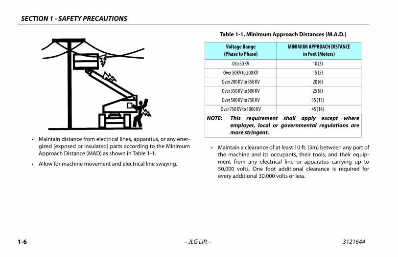
a clearance of at least 10 ft. (3m) between any part ofhine and its occupants, their tools, and their equip-m any electrical line or apparatus carrying up toolts. One foot additional clearance is required forditional 30,000 volts or less.
-1. Minimum Approach Distances (M.A.D.)
e Rangeto Phase)
MINIMUM APPROACH DISTANCEin Feet (Meters)
50 KV 10 (3)
V to 200 KV 15 (5)
V to 350 KV 20 (6)
V to 500 KV 25 (8)
V to 750 KV 35 (11)
V to 1000 KV 45 (14)
requirement shall apply except whereloyer, local or governmental regulations are
re stringent.
– JLG Lift –
• Maintain distance from electrical lines, apparatus, or any ener-gized (exposed or insulated) parts according to the MinimumApproach Distance (MAD) as shown in Table 1-1.
• Allow for machine movement and electrical line swaying.
• Maintainthe macment fro50,000 vevery ad
Table 1
Voltag(Phase
0 to
Over 50K
Over 200 K
Over 350 K
Over 500 K
Over 750 K
NOTE: Thisempmo
SECTION 1 - SAFETY PRECAUTIONS
1-7
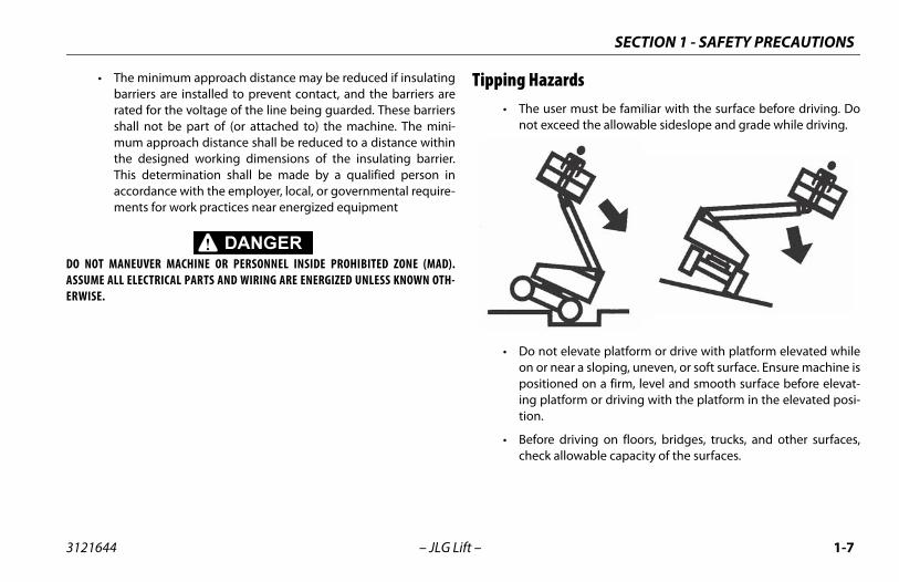
azards user must be familiar with the surface before driving. Doexceed the allowable sideslope and grade while driving.
not elevate platform or drive with platform elevated whiler near a sloping, uneven, or soft surface. Ensure machine is
itioned on a firm, level and smooth surface before elevat-platform or driving with the platform in the elevated posi-.
re driving on floors, bridges, trucks, and other surfaces,ck allowable capacity of the surfaces.
3121644 – JLG Lift –
• The minimum approach distance may be reduced if insulatingbarriers are installed to prevent contact, and the barriers arerated for the voltage of the line being guarded. These barriersshall not be part of (or attached to) the machine. The mini-mum approach distance shall be reduced to a distance withinthe designed working dimensions of the insulating barrier.This determination shall be made by a qualified person inaccordance with the employer, local, or governmental require-ments for work practices near energized equipment
DO NOT MANEUVER MACHINE OR PERSONNEL INSIDE PROHIBITED ZONE (MAD).ASSUME ALL ELECTRICAL PARTS AND WIRING ARE ENERGIZED UNLESS KNOWN OTH-ERWISE.
Tipping H• The
not
• Do on oposing tion
• Befoche

SECTION 1 - SAFETY PRECAUTIONS
1-8 3121644
perate the machine when wind conditions exceed 28.5 m/s). Refer to Table 1-2, Beaufort Scale (For Refer-y).
ncrease the surface area of the platform or the load.of the area exposed to the wind will decrease stabil-
increase the platform size with unauthorized deckns or attachments.
assembly or platform is in a position that one or morere off the ground, all persons must be removed beforeng to stabilize the machine. Use cranes, forklift trucks,appropriate equipment to stabilize machine.
– JLG Lift –
• Never exceed the maximum work load as specified on theplatform. Keep all loads within the confines of the platform,unless authorized by JLG.
• Keep the chassis of the machine a minimum of 2 ft. (0.6m)from holes, bumps, drop-offs, obstructions, debris, concealedholes, and other potential hazards at the ground level.
• Do not push or pull any object with the boom.
• Never attempt to use the machine as a crane. Do not tie-offmachine to any adjacent structure. Never attach wire, cable, orany similar items to platform.
• Do not omph (12ence Onl
• Do not iIncrease ity.
• Do not extensio
• If boom wheels aattemptior other

SECTION 1 - SAFETY PRECAUTIONS
1-9
nce Only)
Land Conditions
vertically
le in smoke
ed skin. Leaves rustle
twigs in constant motion
er raised. Small branches begin to move.
.
otion. Flags waving near horizontal. Umbrella use
ion. Effort needed to walk against the wind.
trees. Cars veer on road.
age.
3121644 – JLG Lift –
DO NOT OPERATE THE MACHINE WHEN WIND CONDITIONS EXCEED 28 MPH (12.5 M/S).
Table 1-2. Beaufort Scale (For Refere
Beaufort Number
Wind SpeedDescription
mph m/s
0 0 0-0.2 Calm Calm. Smoke rises
1 1-3 0.3-1.5 Light air Wind motion visib
2 4-7 1.6-3.3 Light breeze Wind felt on expos
3 8-12 3.4-5.4 Gentle breeze Leaves and smaller
4 13-18 5.5-7.9 Moderate breeze Dust and loose pap
5 19-24 8.0-10.7 Fresh breeze Smaller trees sway
6 25-31 10.8-13.8 Strong breeze Large branches in mbecomes difficult.
7 32-38 13.9-17.1 Near Gale/Moderate Gale Whole trees in mot
8 39-46 17.2-20.7 Fresh Gale Twigs broken from
9 47-54 20.8-24.4 Strong Gale Light structure dam

SECTION 1 - SAFETY PRECAUTIONS
1-1 3121644
Cru n-operating personnel at least 6 ft. (1.8m) away from during all driving and swing operations.
ll travel conditions, the operator must limit travelcording to conditions of ground surface, congestion, slope, location of personnel, and other factors whichse collision or injury to personnel.
of stopping distances in all drive speeds. When driv-h speed, switch to low speed before stopping. Travel low speed only.
se high speed drive in restricted or close quarters orving in reverse.
extreme caution at all times to prevent obstacles fromr interfering with operating controls and persons in
orm.
that operators of other overhead and floor levels are aware of the aerial work platform’s presence. Dis-power to overhead cranes.
rsonnel not to work, stand, or walk under a raised platform. Position barricades on floor if necessary.
0 – JLG Lift –
shing and Collision Hazards• Approved head gear must be worn by all operating and
ground personnel.
• Check work area for clearances overhead, on sides, and bot-tom of platform when lifting or lowering platform, and driving.
• During operation, keep all body parts inside platform railing.
• Use the boom functions, not the drive function, to position theplatform close to obstacles.
• Always post a lookout when driving in areas where vision isobstructed.
• Keep nomachine
• Under aspeed acvisibility,may cau
• Be awareing in higgrades in
• Do not uwhen dri
• Exercise striking othe platf
• Be sure machineconnect
• Warn peboom or
SECTION 1 - SAFETY PRECAUTIONS
1-11
INTENANCEb-section contains general safety precautions which musterved during maintenance of this machine. Additional pre-ns to be observed during machine maintenance ared at the appropriate points in this manual and in the Ser-d Maintenance Manual. It is of utmost importance thatnance personnel pay strict attention to these precautionsd possible injury to personnel or damage to the machineerty. A maintenance program must be established by a
ied person and must be followed to ensure that thee is safe.
nce Hazardst off power to all controls and ensure that all moving partssecured from inadvertent motion prior to performing anystments or repairs.
er work under an elevated platform until it has been fullyered to the full down position, if possible, or otherwiseported and restrained from movement with appropriatety props, blocking, or overhead supports.
NOT attempt to repair or tighten any hydraulic hoses or fit-s while the machine is powered on or when the hydraulicem is under pressure.
ays relieve hydraulic pressure from all hydraulic circuitsre loosening or removing hydraulic components.
3121644 – JLG Lift –
1.4 TOWING, LIFTING, AND HAULING• Never allow personnel in platform while towing, lifting, or
hauling.
• This machine should not be towed, except in the event ofemergency, malfunction, power failure, or loading/unloading.Refer to the Emergency Procedures section of this manual foremergency towing procedures.
• Ensure boom is in the stowed position and the turntablelocked prior to towing, lifting or hauling. The platform must becompletely empty of tools.
• When lifting machine, lift only at designated areas of themachine. Lift the unit with equipment of adequate capacity.
• Refer to the Machine Operation section of this manual for lift-ing information.
1.5 MAThis sube obscautioinsertevice anmainteto avoior propqualifmachin
Maintena• Shu
are adju
• Nevlowsupsafe
• DO tingsyst
• Alwbefo
SECTION 1 - SAFETY PRECAUTIONS
1-1 3121644
se machine as a ground for welding.
rforming welding or metal cutting operations, pre- must be taken to protect the chassis from direct to weld and metal cutting spatter.
fuel the machine with the engine running.
approved non-flammable cleaning solvents.
eplace items critical to stability, such as batteries ors, with items of different weight or specification. Doify unit in any way to affect stability.
the Service and Maintenance Manual for the weightsl stability items.
LTERATION OF AN AERIAL WORK PLATFORM SHALL BE MADERITTEN PERMISSION FROM THE MANUFACTURER.
2 – JLG Lift –
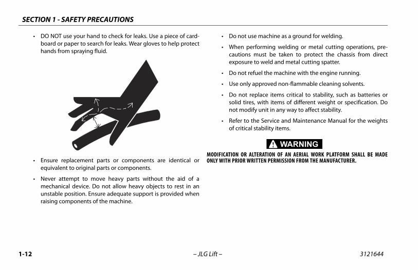
• DO NOT use your hand to check for leaks. Use a piece of card-board or paper to search for leaks. Wear gloves to help protecthands from spraying fluid.
• Ensure replacement parts or components are identical orequivalent to original parts or components.
• Never attempt to move heavy parts without the aid of amechanical device. Do not allow heavy objects to rest in anunstable position. Ensure adequate support is provided whenraising components of the machine.
• Do not u
• When pecautionsexposure
• Do not re
• Use only
• Do not rsolid tirenot mod
• Refer to of critica
MODIFICATION OR AONLY WITH PRIOR W

SECTION 1 - SAFETY PRECAUTIONS
1-13
ID IS HIGHLY CORROSIVE. AVOID CONTACT WITH SKIN AND ALL TIMES. IMMEDIATELY RINSE ANY CONTACTED AREA WITH AND SEEK MEDICAL ATTENTION.
rge batteries only in a well ventilated area.
id overfilling the battery fluid level. Add distilled water toeries only after the batteries are fully charged.
3121644 – JLG Lift –
Battery Hazards• Always disconnect batteries when servicing electrical compo-
nents or when performing welding on the machine.
• Do not allow smoking, open flame, or sparks near battery dur-ing charging or servicing.
• Do not contact tools or other metal objects across the batteryterminals.
• Always wear hand, eye, and face protection when servicingbatteries. Ensure that battery acid does not come in contactwith skin or clothing.
BATTERY FLUCLOTHING ATCLEAN WATER
• Cha
• Avobatt
SECTION 1 - SAFETY PRECAUTIONS
1-1 3121644
4 – JLG Lift –NOTES:
S, MACHINE PREPARATION, AND INSPECTION
2-1
REPARATION, AND INSPECTION
e safest means to operate the machine where overheadstructions, other moving equipment, and obstacles,pressions, holes, drop-offs.
eans to avoid the hazards of unprotected electrical con-ctors.
ecific job requirements or machine application.
upervisiong must be done under the supervision of a qualified per- an open area free of obstructions until the trainee hasped the ability to safely control and operate the machine.
esponsibilityerator must be instructed that he/she has the responsibil- authority to shut down the machine in case of a malfunc- other unsafe condition of either the machine or the job
SECTION 2 - USER RESPONSIBILITIE
3121644 – JLG Lift –
SECTION 2. USER RESPONSIBILITIES, MACHINE P
2.1 PERSONNEL TRAININGThe aerial platform is a personnel handling device; so it is neces-sary that it be operated and maintained only by trained person-nel.
Persons under the influence of drugs or alcohol or who are sub-ject to seizures, dizziness or loss of physical control must notoperate this machine.
Operator TrainingOperator training must cover:
1. Use and limitations of the controls in the platform and at theground, emergency controls and safety systems.
2. Control labels, instructions, and warnings on the machine.
3. Rules of the employer and government regulations.
4. Use of approved fall protection device.
5. Enough knowledge of the mechanical operation of themachine to recognize a malfunction or potential malfunc-tion.
6. Thobde
7. Mdu
8. Sp
Training STraininson indevelo
Operator RThe opity andtion orsite.

SECTION 2 - USER RESPONSIBILITIES, MACHINE PREPARATION, AND INSPECTION
2-2 3121644
2.2. RECOGNIZES A FACTORY TRAINED SERVICE TECHNICIAN AS A
UCCESSFULLY COMPLETED THE JLG SERVICE TRAINING SCHOOL PRODUCT MODEL.
– JLG Lift –
PREPARATION, INSPECTION, AND MAINTENANCEThe following table covers the periodic machine inspections andmaintenance recommended by JLG Industries, Inc. Consult localregulations for further requirements for aerial work platforms.The frequency of inspections and maintenance must beincreased as necessary when the machine is used in a harsh orhostile environment, if the machine is used with increased fre-quency, or if the machine is used in a severe manner.
JLG INDUSTRIES, INCPERSON WHO HAS SFOR THE SPECIFIC JLG

S, MACHINE PREPARATION, AND INSPECTION
2-3
nce Table
ryility
Service Qualification
Reference
User or Operator Operator and Safety Manual
User Qualified JLG Mechanic Service and Maintenance Manual and applicable JLG inspection form
User Qualified JLG Mechanic Service and Maintenance Manual and applicable JLG inspection form
User Factory Trained Service Technician (Recommended)
Service and Maintenance Manual and applicable JLG inspection form
User Qualified JLG Mechanic Service and Maintenance Manual
ual to perform inspections.
SECTION 2 - USER RESPONSIBILITIE
3121644 – JLG Lift –
Table 2-1.Inspection and Maintena
Type FrequencyPrima
Responsib
Pre-Start Inspection Before using each day; or whenever there’s an Operator change.
User or Operator
Pre-Delivery Inspection (See Note) Before each sale, lease, or rental delivery. Owner, Dealer, or
Frequent Inspection In service for 3 months or 150 hours, whichever comes first; orOut of service for a period of more than 3 months; orPurchased used.
Owner, Dealer, or
Annual Machine Inspection Annually, no later than 13 months from the date of prior inspection.
Owner, Dealer, or
Preventative Maintenance At intervals as specified in the Service and Maintenance Manual.
Owner, Dealer, or
NOTE: Inspection forms are available from JLG. Use the Service and Maintenance Man

SECTION 2 - USER RESPONSIBILITIES, MACHINE PREPARATION, AND INSPECTION
2-4 3121644
Pre Around” Inspection – Refer to Figure 2-2. thru Fig-.
y – Charge as required.
ombustion Engine Powered Machines) – Add the fuel as necessary.
ulic Oil – Check the hydraulic oil level. Ensure hydrau- added as required.
on Check – Once the “Walk-Around” Inspection iste, perform a functional check of all systems in ane of overhead and ground level obstructions. Refer to 4 for more specific instructions.
ES NOT OPERATE PROPERLY, TURN OFF THE MACHINE IMMEDI-PROBLEM TO THE PROPER MAINTENANCE PERSONNEL. DO NOTNE UNTIL IT IS DECLARED SAFE FOR OPERATION.
– JLG Lift –
-Start InspectionThe Pre-Start Inspection should include each of the following:
1. Cleanliness – Check all surfaces for leakage (oil, fuel, or bat-tery fluid) or foreign objects. Report any leakage to theproper maintenance personnel.
2. Structure - Inspect the machine structure for dents, dam-age, weld or parent metal cracks or other discrepancies.
3. Decals and Placards – Check all for cleanliness and legibil-ity. Make sure none of the decals and placards are missing.Make sure all illegible decals and placards are cleaned orreplaced.
4. Operators and Safety Manuals – Make sure a copy of theOperator and Safety Manual, AEM Safety Manual (Domesticonly), and ANSI Manual of Responsibilities (Domestic only) isenclosed in the weather resistant storage container.
5. “Walk-ure 2-4
6. Batter
7. Fuel (Cproper
8. Hydralic oil is
9. Functicomplearea freSection
IF THE MACHINE DOATELY! REPORT THE OPERATE THE MACHI
Parent Metal Crack Weld Crack

S, MACHINE PREPARATION, AND INSPECTION
2-5
tower boom does not rest on stop with machine in theowed position, this indicates upright is out of plumb.
lescope boom IN and OUT several cycles at variousgrees of elevation lengths. Check for smooth telescopeeration.
ing turntable to LEFT and RIGHT a minimum of 45grees. Check for smooth motion.
eck the chassis tilt indicator located on the platform con-l console by driving, with the machine in stowed position, a suitable ramp of at least 6° slope. Check the tilt alarm,
ith the machine on the ramp, raise the upper boom until itparallel with the chassis. DO NOT RAISE ABOVE THE PARAL-L POSITION. If the light does not illuminate, return theachine to a level surface, shut down the machine, and con-ct a qualified technician before resuming operation.
r units equipped with optional tilt cutout, verify that theive function is cutout when the boom is elevated and tiltarm is activated.
E ON GRADES WHICH EXCEED THE RATED GRADEABILITY OF THEDICATED ON THE SERIAL NUMBER PLATE. DO NOT DRIVE ON SIDES-XCEED 5 DEGREES.
SECTION 2 - USER RESPONSIBILITIE
3121644 – JLG Lift –
Function CheckA functional check of all systems should be performed, once thewalk-around inspection is complete, in an area free of overheadand ground level obstructions. First, using the ground controls,check all functions controlled by the ground controls. Next, usingthe platform controls, check all functions controlled by the plat-form controls.
TO AVOID SERIOUS INJURY, DO NOT OPERATE MACHINE IF ANY CONTROL LEVERS ORTOGGLE SWITCHES CONTROLLING PLATFORM MOVEMENTS DO NOT RETURN TO THEOFF POSITION WHEN RELEASED.
TO AVOID A COLLISION AND INJURY IF PLATFORM DOES NOT STOP WHEN A CONTROLSWITCH OR LEVER IS RELEASED, REMOVE FOOT FROM FOOTSWITCH OR USE EMER-GENCY STOP TO STOP MACHINE.
1. Check boom limit switches. Raise and lower the LowerBoom. Check for smooth operation.
NOTE: Perform checks from ground controls first, then from platformcontrols.
2. Raise, extend, retract, and lower the Upper Boom. Check forsmooth operation.
3. If st
4. Tedeop
5. Swde
6. Chtroupwis LEmta
Fodral
DO NOT DRIVMACHINE AS INLOPES WHICH E

SECTION 2 - USER RESPONSIBILITIES, MACHINE PREPARATION, AND INSPECTION
2-6 3121644
FOOTIS AP4" (6
FOOTOTHE
he GROUND/PLATFORM SELECT switch to GROUND.m controls should not operate.
ROUND/PLATFORM SELECT switch to OFF. Platform/ controls should not operate.
– JLG Lift –
7. Check that platform self-leveling system functions properlyduring raising and lowering of boom.
8. Check rotator for smooth operation and assure platform willrotate 75 degrees in both directions from centerline ofboom.
9. Drive forward and reverse; check for proper operation.
10. Steer left and right; check for proper operation.
11. Footswitch.
SWITCH MUST BE ADJUSTED SO THAT FUNCTIONS WILL OPERATE WHEN PEDALPROXIMATELY AT ITS CENTER OF TRAVEL. IF SWITCH OPERATES WITHIN LAST 1/ MM) OF TRAVEL, TOP OR BOTTOM, IT SHOULD BE ADJUSTED.
SWITCH MUST BE DEPRESSED PRIOR TO ACTIVATING ANY FUNCTION CONTROL,RWISE THE FUNCTION WILL NOT WORK.
With footswitch depressed, operate LIFT and hold control.Remove foot from footswitch, motion should stop. If it doesnot, shut down machine and contact a qualified service techni-cian.
12. Place tPlatfor
13. Place GGround
S, MACHINE PREPARATION, AND INSPECTION
2-7
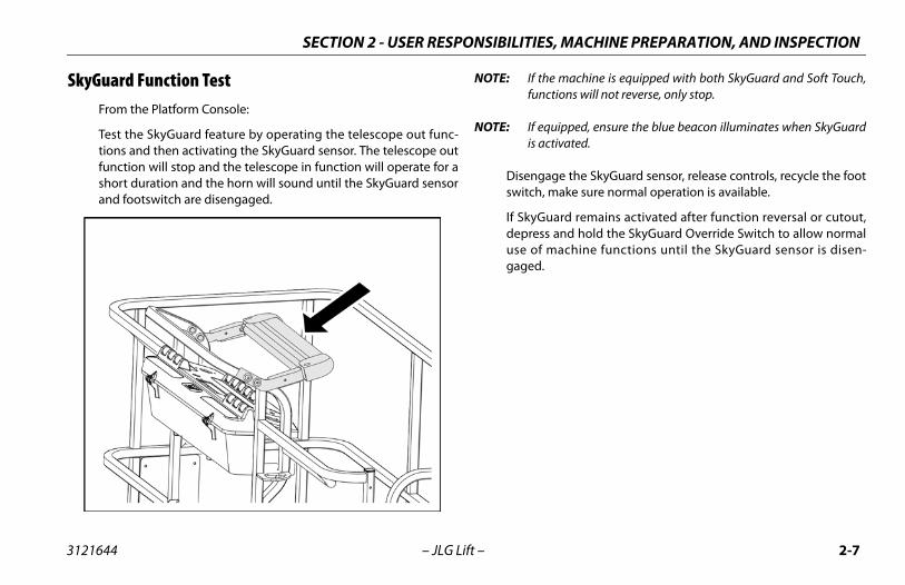
he machine is equipped with both SkyGuard and Soft Touch,ctions will not reverse, only stop.
quipped, ensure the blue beacon illuminates when SkyGuardctivated.
age the SkyGuard sensor, release controls, recycle the foot, make sure normal operation is available.
uard remains activated after function reversal or cutout,s and hold the SkyGuard Override Switch to allow normal machine functions until the SkyGuard sensor is disen-
SECTION 2 - USER RESPONSIBILITIE
3121644 – JLG Lift –
SkyGuard Function Test From the Platform Console:
Test the SkyGuard feature by operating the telescope out func-tions and then activating the SkyGuard sensor. The telescope outfunction will stop and the telescope in function will operate for ashort duration and the horn will sound until the SkyGuard sensorand footswitch are disengaged.
NOTE: If tfun
NOTE: If eis a
Disengswitch
If SkyGdepresuse ofgaged.

SECTION 2 - USER RESPONSIBILITIES, MACHINE PREPARATION, AND INSPECTION
2-8 3121644
1. Platform Control Console2. Platform3. Upper Boom4. Telescope Cylinder (inside)5. Master Cylinder6. Upper Upright7. Upper Lift Cylinder8. Mid Lift Cylinder9. Lower Boom10. Turntable11. Frame12. Steer Wheels13. Drive Wheels14. Battery Box15. Lower Lift Cylinder16. Lower Link17. Lower Upright18. Upper Link19. Mid Boom20. Slave Cylinder21. Footswitch22. SkyGuard (If Equipped)
– JLG Lift –
Figure 2-1. Basic Nomenclature

S, MACHINE PREPARATION, AND INSPECTION
2-9
n - Sheet 1 of 3
SECTION 2 - USER RESPONSIBILITIE
3121644 – JLG Lift –
Figure 2-2. Daily Walk-Around Inspectio

SECTION 2 - USER RESPONSIBILITIES, MACHINE PREPARATION, AND INSPECTION
2-1 3121644
Ge
TO AARO
DO AREMAC
NO
rm and Gate Assembly - Platform mounting pins. Footswitch in good working order; not modified,
ed or blocked; Bar slides freely.
rm & Ground Control Console - Switches and levers to neutral and are properly secured, decals/placards and legible, control marking legible.
r - See Note.
ee Note.
tator - See Note.
Sections - See Note.
draulic Cylinders - No visible damage; pivot pins andulic hoses undamaged, not leaking.
witches - See Note.
eet 2 of 3
0 – JLG Lift –
neralBegin the “Walk-Around Inspection” at Item 1, as noted on thediagram. Continue to the right (counterclockwise viewed fromtop) checking each item in sequence for the conditions listed inthe “Walk-Around Inspection Checklist”.
VOID POSSIBLE INJURY BE SURE MACHINE POWER IS OFF DURING "WALK-UND INSPECTION".
NOT OVERLOOK VISUAL INSPECTION OF CHASSIS UNDERSIDE. CHECKING THISA MAY RESULT IN DISCOVERY OF CONDITIONS WHICH COULD CAUSE EXTENSIVEHINE DAMAGE.
TE: On each item, make sure there are no loose or missing parts,that they are securely fastened and that no visible damageexists in addition to any other criteria mentioned.
1. Platfosecuredisabl
2. Platforeturnsecure
3. Rotato
4. Jib - S
5. Jib Ro
6. Boom
7. All Hyhydra
8. Limit S
Figure 2-3. Daily Walk-Around Inspection - Sh

S, MACHINE PREPARATION, AND INSPECTION
2-11
attery Charger - See Note.
rake/Steer Valve - See Note.
oom/Upright - No visible damage; All pins properlyecured. Upright in vertical position. If Upright does notest on stop with machine in the stowed position, this indi-ates upright is out of plumb.
ounterweight - See Note.
ie Rod Ends and Steering Spindles - See Note. Tie rod endtubs locked.
anual Descent Valve - See Note.
ontrol Valve - See Note.
rame - See Note.
latform Pivot Pins - Properly secured.
kyGuard - See Inspection Note.
- Sheet 3 of 3
SECTION 2 - USER RESPONSIBILITIE
3121644 – JLG Lift –
9. Drive Axle and Motor - See Note.
10. Wheel/Tire Assembly - No loose or missing lug nuts.Inspect for worn tread, cuts, tears or other discrepancies.Inspect wheels for damage and corrosion.
11. Swing Motor and Worm Gear - See Note.
12. Hydraulic Pump and Reservoir - Properly secured; no visi-ble damage or hydraulic leaks. Recommended hydraulicfluid level on dipstick (system shut down, boom in stowedposition). Breather cap/dipstick secure and working.
13. Turntable Bearing - No loose or missing hardware; no visi-ble damage; evidence of proper lubrication. No loose boltsor looseness between bearing and structure.
14. Battery Compartment Right Side - Batteries have properelectrolyte level; cables tight; no visible damage or corro-sion.
15. Cowling and Latches - See Note.
16. B
17. B
18. Bsrc
19. C
20. Ts
21. M
22. C
23. F
24. P
25. S
Figure 2-4. Daily Walk-Around Inspection

SECTION 2 - USER RESPONSIBILITIES, MACHINE PREPARATION, AND INSPECTION
2-1 3121644
2 – JLG Lift –NOTES:

N 3 - MACHINE CONTROLS AND INDICATORS
3-1
ND INDICATORS indicator panels use different shaped symbols to alert therator to different types of operational situations that could
se. The meaning of those symbols are explained below.Indicates a potentially hazardous situation, which ifnot corrected, could result in serious injury or death.This indicator will be red.
Indicates an abnormal operating condition, which ifnot corrected, may result in machine interruption ordamage. This indicator will be yellow.
Indicates important information regarding the oper-ating condition, i.e. procedures essential for safe oper-ation. This indicator will be green with the exception ofthe capacity indicator which will be green or yellowdepending upon platform position.
SECTIO
3121644 – JLG Lift –
SECTION 3. MACHINE CONTROLS A
3.1 GENERAL
THE MANUFACTURER HAS NO DIRECT CONTROL OVER MACHINE APPLICATION ANDOPERATION. THE USER AND OPERATOR ARE RESPONSIBLE FOR CONFORMING WITHGOOD SAFETY PRACTICES.
This section provides the necessary information needed tounderstand control functions.
3.2 CONTROLS AND INDICATORS
NOTE: This machines is equipped with control panels that use symbolsto indicate control functions. On ANSI machines, refer to decallocated on the control box guard in front of the control box or bythe ground controls for these symbols and the correspondingfunctions.
NOTE: Theopeari

SECTION 3 - MACHINE CONTROLS AND INDICATORS
3-2 3121644
Gro
(S
NOT
NOT
NOT
m Overload (If equipped)
es the platform has been overloaded.
tor/Engine Start Button
enerator/engine start push-button allows the generator to be startedlly to top-off the battery charge. Thetor will start automatically when thees reach a low-charge state and the Generator Enable on the platform console is in the on position.
ine will not start if the batteries are fully charged or if theor Enable switch on the platform console is not in the on.
Indicator and Hourmeter
urmeter, installed in the upper por- the Ground Control Box, registers thet of machine operating time. Theeter registers up to 9,999.9 hours and be reset.
– JLG Lift –
und Control Station
ee Figure 3-1. and Figure 3-2.)
E: When machine is shut down the Platform/Ground Select switchand Emergency Stop must be positioned to Off.
E: The Function Enable switch must be held down in order to oper-ate Telescope, Lower Lift, Swing, Main Lift, Jib Lift, Platform LevelOverride, and Platform Rotate functions.
1. System Distress Indicator (If Equipped)
The system distress indicator lights to sig-nify an abnormal condition for the genera-tor engine (high oil temperature or low oilpressure) or, on electric machines, an elec-trical system fault.
E: The engine will automatically shut down under the followingconditions:
High Oil TemperatureLow Oil PressureEngine OverspeedOvervoltage
2. Platfor
Indicat
3. Genera
The gswitchmanuagenerabatteriswitch
NOTE: The engGeneratposition
4. Battery
An hotion ofamounhourmcannot

N 3 - MACHINE CONTROLS AND INDICATORS
3-3
tion
1. System Distress Indicator2. Platform Overload Indicator3. Engine/Generator Start Button4. Battery Condition Indicator & Hourmeter5. Telescope6. Swing7. Function Enable8. Circuit Breakers9. Emergency Stop10. Platform/Ground Select11. Lower/Mid Lift12. Upper Boom Lift13. Jib14. Platform Leveling15. Rotate
SECTIO
3121644 – JLG Lift –
Figure 3-1. Ground Control Sta

SECTION 3 - MACHINE CONTROLS AND INDICATORS
3-4 3121644
Override (MSSO) (CE Only)
1. System Distress Indicator2. Platform Overload Indicator3. Engine/Generator Start Button4. Not Used5. Telescope6. Swing7. Function Enable8. Circuit Breakers9. Emergency Stop10. Platform/Ground Select11. Lower/Mid Lift12. Upper Boom Lift13. Jib14. Platform Leveling15. Rotate16. Indicator Gauge17. Charger Status18. Machine Safety System Override (MSSO)
– JLG Lift –
Figure 3-2. Ground Control Station with Machine Safety System
N 3 - MACHINE CONTROLS AND INDICATORS
3-5
wer/Emergency Stop Switch
two-position red mushroom shaped switchrnishes power to Platform/Ground Selectitch when pulled out (on). When pushed in
ff ), power is shut off to the Platform/Ground Select switch.
atform/Ground Select Switch
three position, key operated switchpplies power to the platform controlnsole when positioned to Platform.ith the switch key in the Ground posi-n, power is shut off to platform andly ground controls are operable.
h Platform/Ground Select switch in the center position,er is shut off to controls at both operating stations.
SECTIO
3121644 – JLG Lift –
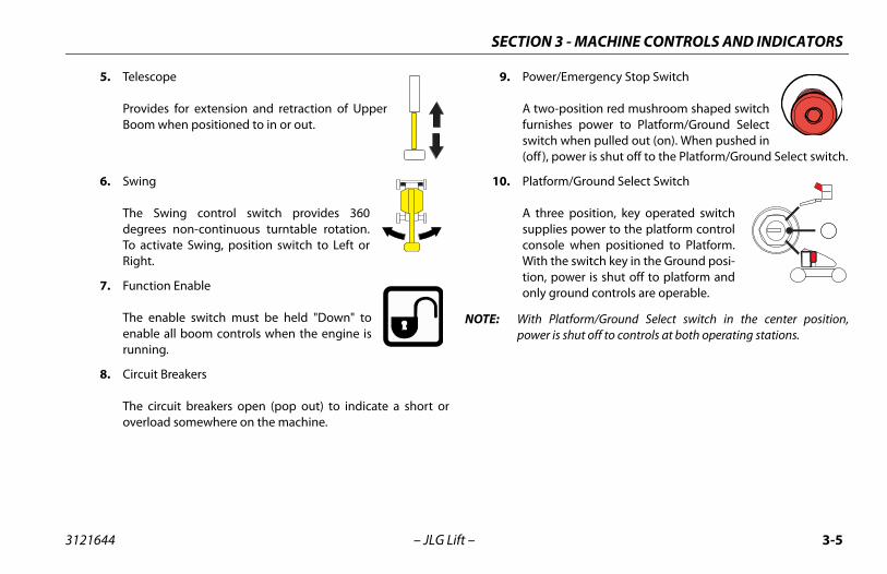
5. Telescope
Provides for extension and retraction of UpperBoom when positioned to in or out.
6. Swing
The Swing control switch provides 360degrees non-continuous turntable rotation.To activate Swing, position switch to Left orRight.
7. Function Enable
The enable switch must be held "Down" toenable all boom controls when the engine isrunning.
8. Circuit Breakers
The circuit breakers open (pop out) to indicate a short oroverload somewhere on the machine.
9. Po
A fusw(o
10. Pl
A sucoWtioon
NOTE: Witpow

SECTION 3 - MACHINE CONTROLS AND INDICATORS
3-6 3121644
ORM LEVELING OVERRIDE FUNCTION FOR SLIGHT LEVELING OFORRECT USE COULD CAUSE THE LOAD/OCCUPANT TO SHIFT OR SO COULD RESULT IN DEATH OR SERIOUS INJURY.
m Leveling Override
position switch allows the operator tothe automatic self leveling system. This is used to adjust platform level in situa-
ch as ascending/descending a grade.
position Rotate control switch permitsn of the platform when positioned to leftt.
– JLG Lift –
11. Lower/Mid Boom Lift
Provides for raising and lowering ofLower Boom when positioned to Up orDown.
12. Upper Boom Lift
Provides for raising and lowering of UpperBoom when positioned to Up or Down.
13. Jib (If equipped)
The Jib control switch provides raising andlowering of the jib when positioned up ordown.
ONLY USE THE PLATFTHE PLATFORM. INCFALL. FAILURE TO DO
14. Platfor
A threeadjust switchtions su
15. Rotate
A threerotatioor righ
N 3 - MACHINE CONTROLS AND INDICATORS
3-7
tation
3-4.)
si-Track Control
tivating the Posi-Track switch allowse operator to engage positive trac-n for the time period pre-set in thentroller. Posi-traction occurs by changing the drive motorsm a series to parallel arrangement, causing availablewer to be distributed evenly between the two drive
heels. The control system may also engage the posi-tracknction automatically.
PLATFORM LEVELING OVERRIDE FUNCTION FOR SLIGHT LEVELING OF. INCORRECT USE COULD CAUSE THE LOAD/OCCUPANT TO SHIFT OR
TO DO SO COULD RESULT IN DEATH OR SERIOUS INJURY.
atform Leveling Override
three position switch allows the operator tojust the automatic self leveling system. Thisitch is used to adjust platform level in situa-ns such as ascending/descending a grade.
SECTIO
3121644 – JLG Lift –
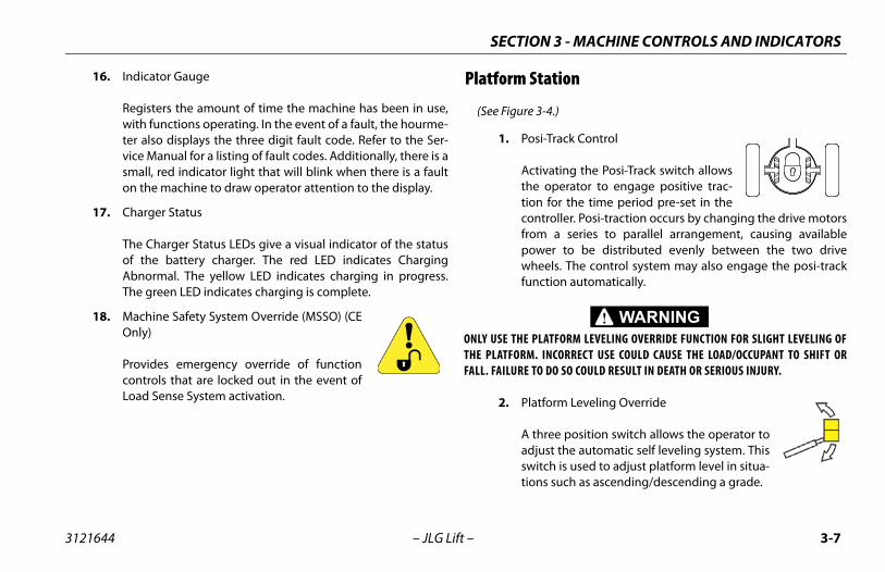
16. Indicator Gauge
Registers the amount of time the machine has been in use,with functions operating. In the event of a fault, the hourme-ter also displays the three digit fault code. Refer to the Ser-vice Manual for a listing of fault codes. Additionally, there is asmall, red indicator light that will blink when there is a faulton the machine to draw operator attention to the display.
17. Charger Status
The Charger Status LEDs give a visual indicator of the statusof the battery charger. The red LED indicates ChargingAbnormal. The yellow LED indicates charging in progress.The green LED indicates charging is complete.
18. Machine Safety System Override (MSSO) (CEOnly)
Provides emergency override of functioncontrols that are locked out in the event ofLoad Sense System activation.
Platform S
(See Figure
1. Po
Acthtiocofropowfu
ONLY USE THE THE PLATFORMFALL. FAILURE
2. Pl
A adswtio
SECTION 3 - MACHINE CONTROLS AND INDICATORS
3-8 3121644
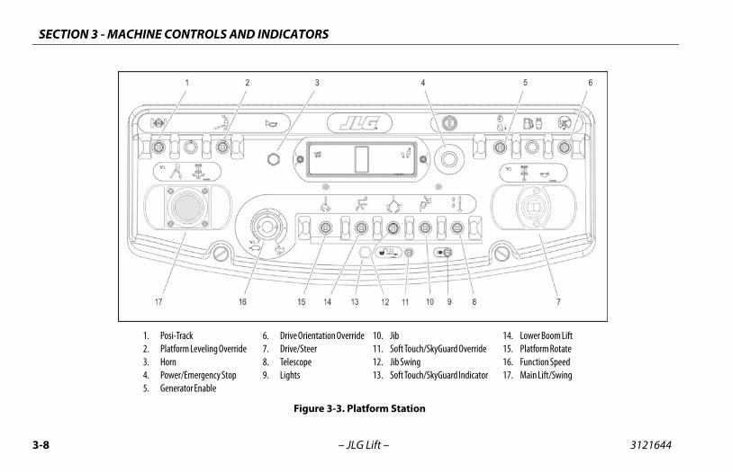
uard Override
uard Indicator
14. Lower Boom Lift15. Platform Rotate16. Function Speed17. Main Lift/Swing
– JLG Lift –
1. Posi-Track2. Platform Leveling Override3. Horn4. Power/Emergency Stop5. Generator Enable
6. Drive Orientation Override7. Drive/Steer8. Telescope9. Lights
10. Jib11. Soft Touch/SkyG12. Jib Swing13. Soft Touch/SkyG
Figure 3-3. Platform Station

N 3 - MACHINE CONTROLS AND INDICATORS
3-9
ive Orientation Override
hen the boom is swung over the rear tires further in either direction, the Drive Orien-tion indicator will illuminate when the drivenction is selected. Push and release theitch, and within 3 seconds move the Drive/Steer control
activate drive or steer. Before driving, locate the black/hite orientation arrows on both the chassis and the plat-rm controls and match the control direction arrow to thetended direction of travel.
SECTIO
3121644 – JLG Lift –
3. Horn
A push-type Horn switch supplies electricalpower to an audible warning device when pressed.
4. Power/Emergency Stop
A two-position red mushroom shaped switchfurnishes power to Platform Controls whenpulled out (on). When pushed in (off ), power isshut off to the platform functions.
Within about 2 seconds of pulling the switch out, themachine will perform a diagnostic check of the various elec-trical circuits, and if everything is OK, the platform alarm willbeep once. During this time the lights on the indicator panelwill also blink once as a bulb check.
5. Generator Enable Control
The Generator Enable control switch, when inthe off position, allows the operator to preventthe generator engine from starting whenusing the machine indoors. When in the onposition (and the ground Emergency StopSwitch on [pulled out]), the generator is enabled to automat-ically start when the batteries need charged.
6. Dr
Wortafuswtowfoin

SECTION 3 - MACHINE CONTROLS AND INDICATORS
3-1 3121644
NOT
NOT
NOT
NJURY, DO NOT OPERATE MACHINE IF ANY CONTROL LEVERS ORONTROLLING PLATFORM MOVEMENT DO NOT RETURN TO THE
SITION WHEN RELEASED.
pe Control
LESCOPE control switch affords extensiontraction of the main boom when posi- to IN or OUT.
(If Equipped)
itch operates control console paneland head lights if the machine is soed.
quipped)
rward to lift up, pull back to lift down.e lift speed is using the FunctionControl.
0 – JLG Lift –
E: To operate the Drive joystick, pull up on the lock-ing ring below the handle.
E: The Drive joystick is spring loaded and will auto-matically return to neutral (off) position whenreleased.
7. Drive/Steer
The Drive controller provides fordriving either forward or back-ward when positioned to For-ward or Reverse. The controller is‘ramped’ to allow infinitely vari-able drive speed between fastand slow.
Positioning the steer control thumb operated switch Rightor Left enables steering the machine to the right or leftrespectively.
E: When lower boom is raised above horizontal, or the upper boomis raised approximately 16 inches (40.64 cm) above boom rest,the high drive function will automatically switch to low drive.This also occurs when Function Speed Control is clicked on creep.
TO AVOID SERIOUS ITOGGLE SWITCHES COFF OR NEUTRAL PO
8. Telesco
The TEand retioned
9. Lights
This swlights equipp
10. Jib (If E
Push foVariablSpeed

N 3 - MACHINE CONTROLS AND INDICATORS
3-11
Swing
sh toggle switch right to swing right, pushft to swing left.
ft Touch/SkyGuard Indicator (If Equipped)
dicates the Soft Touch bumper is against an object or theyGuard sensor has been activated. All controls are cut outtil the override button is pushed. For Soft Touch, controls
e then active in the Creep Mode or for SkyGuard, controlsill work normally.
wer Boom Lift
ovides for raising and lowering of Lowerd Mid Boom when positioned to UP orWN. Upper lift will not function when
erating lower lift.
SECTIO
3121644 – JLG Lift –
11. Soft Touch/SkyGuard Override Switch (If equipped)
The machine can be equipped with one of three options. Itmay have Soft Touch, SkyGuard, or both Soft Touch and Sky-Guard.
If equipped with Soft Touch, the switchenables the functions that were cut outby the Soft Touch system to operateagain at creep speed, allowing theoperator to move the platform away from the obstacle thatcaused the shutdown situation.
If equipped with SkyGuard, the switchenables functions cut out by the Sky-guard system to be operated again,allowing the operator to resume use ofmachine functions.
If equipped with both Soft Touch andSkyGuard, the switch operates likedescribed above and allows the opera-tor to override the system that hasexperienced a cutout situation.
12. Jib
Pule
13. So
InSkunarw
14. Lo
PranDOop

SECTION 3 - MACHINE CONTROLS AND INDICATORS
3-1 3121644
NOT
in Boom Lift/Swing joystick is spring loaded and willtically return to neutral (off ) position when released.
ift/Swing Controller
s main lift and swing. Push for-o lift up, pull backward to boomMove right to swing right, move
swing left. Moving the joystickes switches to provide the func-lected.
t will not function when operating main lift.
2 – JLG Lift –
15. Platform Rotate
The PLATFORM ROTATE control switch allowsthe operator to rotate the basket to the left orright when positioned to the desired direction.
16. Function Speed Control
Adjusts speed of Boom and Swing Func-tions. Rotate counterclockwise for slowerspeed and clockwise for faster speed. Toadjust Drive, Swing, and Main Lift to creep,turn knob fully counterclockwise until itclicks.
E: To operate the Main Boom Lift/Swing joystick,pull up on the locking ring below the handle.
NOTE: The Maautoma
17. Main L
Provideward tdown. left toactivattions se
NOTE: Lower lif

N 3 - MACHINE CONTROLS AND INDICATORS
3-13
ions
ill Also Work at the Same Time:
Lower Lift** Upper Lift** Telescope
Lower Lift** Upper Lift** Telescope
No Telescope*
No Telescope
Lower Lift** Upper Lift**
Lower Lift** Upper Lift** Telescope
No No No
e to sharing of oil.
perated at full speed, due to sharing of oil.
SECTIO
3121644 – JLG Lift –
Table 3-1. Simultaneous Funct
If This Function is Selected: These Functions W
Drive and Steer Swing
Swing Drive and Steer
Lower Lift Drive and Steer Swing*
Upper Lift Drive and Steer Swing
Telescope Drive and Steer Swing*
Jib Drive and Steer Swing*
Platform Rotate Drive and Steer No
Note: Boom functions may be slower when selected with another function than when operated individually, du
* These functions may move very slowly (or not at all) if the first function selected (Lower Lift or Swing) is being o
** Lower Lift and Upper Lift will not function simultaneously. Upper Lift always prevails.

SECTION 3 - MACHINE CONTROLS AND INDICATORS
3-1 3121644
Pla
(S
IF TIRETRIT IS
m Overload (If equipped)
es the platform has been overloaded.
4 – JLG Lift –
tform Control Indicator Panel
ee Figure 3-4., Platform Control Indicator Panel w/Drive Orientation)
1. Tilt Alarm Warning Light and Alarm
This illuminator indicates that the chassis ison a slope. An alarm will also sound when thechassis is on a slope and the boom is abovehorizontal. If lit when boom is raised orextended, retract and lower to below horizontal then reposi-tion machine so that it is level before continuing operation.If the boom is above horizontal and the machine is on aslope, the tilt alarm warning light will illuminate and analarm will sound and Creep is automatically activated.
LT WARNING LIGHT IS ILLUMINATED WHEN BOOM IS RAISED OR EXTENDED,ACT AND LOWER TO BELOW HORIZONTAL THEN REPOSITION MACHINE SO THATLEVEL BEFORE EXTENDING BOOM OR RAISING BOOM ABOVE HORIZONTAL.
2. Platfor
Indicat

N 3 - MACHINE CONTROLS AND INDICATORS
3-15
Orientation Overrideouch Indicator
/Drive Orientation
SECTIO
3121644 – JLG Lift –
1. Tilt2. Platform Overload3. System Distress
4. Posi-Track5. Enable6. Low Battery
7. Creep8. Drive9. Soft T
Figure 3-4. Platform Control Indicator Panel w
SECTION 3 - MACHINE CONTROLS AND INDICATORS
3-1 3121644
ere is some other fault in one of the circuits. If sotermine the cause by counting the flash code, a num-r of flashes followed by a pause followed by anothermber of flashes, and refer to the service manual.
ine will automatically shut down under the followingns:
gine Oil Temperatureine Oil Pressureverspeed
or Overvoltage
rientation Indicator
the boom is swung beyond therive tires or further in either direc-e Drive Orientation indicator will
ate when the drive function isd. This is a signal for the operator to verify that
ive control is being operated in the proper direc-e. controls reversed situations).
6 – JLG Lift –
3. System Distress Indicator
The system distress indicator lights to signifyan abnormal condition for the generatorengine (high oil temperature or low oil pres-sure) or, on all electric machines, an electricalsystem fault.
The four likely causes of a system fault are:
a. The seven second enable time has been allowed tolapse or a function was selected before depressing thefootswitch. The system reads this condition as a fault,just as it would if the footswitch were jammed in thedepressed position or a function switch were stuck inthe on position. Re-depress the footswitch to power thecontrols and extinguish the light.
b. The maximum power limit has been reached and themachine is not moving. This could happen when themachine is stuck or when attempting to travel overrough terrain or on steep grades which exceed therated gradeability of the machine. This condition iscomparable to stalling the engine by asking it to pro-vide more power than it was designed to do.
c. The batteries are nearly depleted, and should becharged very soon to prevent having the machine stopat an inconvenient place.
d. Thdebenu
NOTE: The engconditio
High EnLow EngEngine OGenerat
4. Drive O
When rear dtion, thilluminselectethe drtion (i.

N 3 - MACHINE CONTROLS AND INDICATORS
3-17
OUS INJURY, DO NOT REMOVE, MODIFY OR DISABLE THE FOOTSWITCHR ANY OTHER MEANS.
UST BE ADJUSTED IF FUNCTIONS ACTIVATE WHEN SWITCH ONLYHIN LAST 1/4" OF TRAVEL, TOP OR BOTTOM.
w Battery Indicator
dicates the batteries are low and need to charged.
SECTIO
3121644 – JLG Lift –
5. Posi-Track Indicator
This indicator lights to show that posi-traction is operating.
6. Enable Indicator/Footswitch
To operate any function, the footswitchmust be depressed and the functionselected within seven seconds. The enableindicator shows that the controls areenabled. If a function is not selected within seven seconds,or if a seven second lapse between ending one function andbeginning the next function, the enable light will go out andthe footswitch must be released and depressed again toenable the controls.
Releasing the footswitch removes power from all controlsand applies the drive brakes.
TO AVOID SERIBY BLOCKING O
FOOTSWITCH MOPERATES WIT
7. Lo
Inbe

SECTION 3 - MACHINE CONTROLS AND INDICATORS
3-1 3121644
Speed Indicator
the Function Speed Control is to the creep position, the indicator a reminder that all functions are setslowest speed.
8 – JLG Lift –
8. Soft Touch Indicator (If Equipped)
When illuminated (Yellow) the Soft Touchbumper is against an object. All controlsare disabled until the override button ispushed, at which time controls are active inthe Creep mode.
9. Creep
When turnedacts asto the
SECTION 4 - MACHINE OPERATION
4-1
RATION
RATING CHARACTERISTICS AND LIMITATIONS
om can be raised above horizontal with or without any platform, if:
achine is positioned on a smooth, firm and level surface.
ad is within manufacturers rated design capacity.
l machine systems are functioning properly.
oper tire pressure.
achine is as originally equipped from JLG.
3121644 – JLG Lift –
SECTION 4. MACHINE OPE
4.1 DESCRIPTIONThis machine is a self-propelled hydraulic personnel lift equippedwith a work platform on the end of an elevating and rotatingboom.
The primary operator control station is in the platform. From thiscontrol station, the operator can drive and steer the machine inboth forward and reverse directions. The operator can raise orlower the upper or lower boom or swing the boom to the left orright. Standard boom swing is 360 degree non-continuous leftand right of the stowed position. The machine has a Ground Con-trol Station which will override the Platform Control Station.Ground Controls operate Upper and Lower Boom Lift and Swing,and are to be used in an emergency to lower the platform to theground should the operator in the platform be unable to do so.
4.2 OPE
CapacitiesThe boload in
1. M
2. Lo
3. Al
4. Pr
5. M
SECTION 4 - MACHINE OPERATION
4-2 3121644
Sta
TO AVATE T
OPERATION
ency StopEmergency Stop switch, when pulledovides battery power for all machinehe switch should be pushed in (off )
arging the batteries or parking theernight.
ped with the optional on-board generator, the Emer-op switch must be left on (pulled out) to allow for auto-arging of the batteries.
ut 2 seconds of pulling the switch out, the machine a diagnostic check of the various electrical circuits,
thing is OK, the platform alarm will beep once. Duringe lights on the indicator panel will also blink once as a
– JLG Lift –
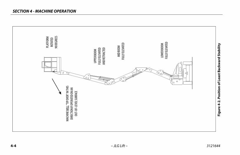
bilityMachine stability is based on two positions which are called For-ward and Backward stability. The machines position of least For-ward stability is shown in Figure 4-1., Position of Least ForwardStability, and its position of least Backward stability is shown inFigure 4-2., Position of Least Backward Stability.
OID FORWARD OR BACKWARD TIPPING, DO NOT OVERLOAD MACHINE OR OPER-HE MACHINE ON AN OUT-OF-LEVEL SURFACE.
4.3 MOTOR
Power/EmergThe Power/out (on), prfunctions. Twhen rechmachine ov
NOTE: If equipgency Stmatic ch
Within abowill performand if everythis time thbulb check.

SECTION 4 - MACHINE OPERATION
4-3
rd Stability
MACHINE WILL "TIP OVER" IN THISDIRECTION IF OPERATED ON AN
OUT-OF-LEVEL SURFACE
BOOM EXTENDED
3121644 – JLG Lift –
Figure 4-1. Position of Least Forwa
FLYFULLY
UPPER BOOMHORIZONTAL
TOWER AND MIDBOOM AT
33 DEGREES
SECTION 4 - MACHINE OPERATION
4-4 3121644
Figu
re 4
-2. P
osit
ion
of L
east
Bac
kwar
d St
abili
ty
LOW
ER BO
OMFU
LLY E
LEVA
TED
– JLG Lift –
MID
BOOM
FULL
Y ELE
VATE
D
UPPE
R BOO
MFU
LLY E
LEVA
TED
AND R
ETRA
CTED
PLAT
FORM
ROTA
TED
90 DE
GREE
S
MAC
HINE
WILL
"TIP
OVER
" IN T
HIS
DIRE
CTIO
N IF O
PERA
TED O
N AN
OUT-
OF-L
EVEL
SURF
ACE
SECTION 4 - MACHINE OPERATION
4-5
VELING (DRIVING)
units equipped with optional tilt cutout, verify that the drivection is cut out when the boom is elevated and tilt alarm isivated.
en lower boom is raised above horizontal, or the upper boomaised approximately 16 inches (40.6 cm) above boom rest, theh drive function will automatically be in low drive.
E IS OPERATED AT A VERY SLOW SPEED OR STALLED WHEN CLIMBING A OR GREATER, DRIVE FUNCTION WILL STOP. REMOVE FOOT FROM
AND DEPRESS FOOTSWITCH TO RESET.
WITH BOOM ABOVE HORIZONTAL EXCEPT ON A SMOOTH, FIRM AND.
OF TRAVEL CONTROL OR “TIP OVER” ON GRADES AND SIDE SLOPES, MACHINE ON GRADES EXCEEDING THOSE SPECIFIED ON THE SERIAL.
ON SIDESLOPES WHICH EXCEED 5 DEGREES.RAIN FEATURES WHICH COULD CAUSE THE MACHINE TO TIP OVER.
3121644 – JLG Lift –
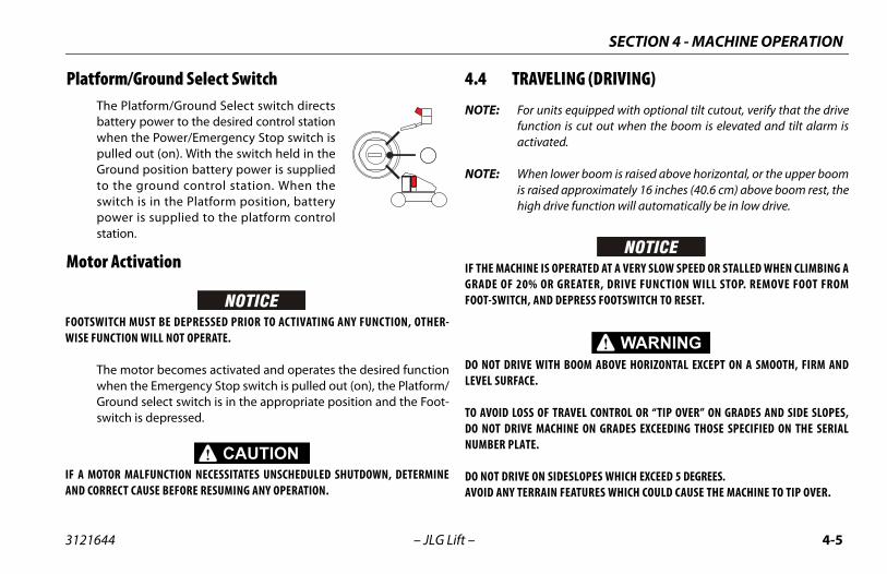
Platform/Ground Select SwitchThe Platform/Ground Select switch directsbattery power to the desired control stationwhen the Power/Emergency Stop switch ispulled out (on). With the switch held in theGround position battery power is suppliedto the ground control station. When theswitch is in the Platform position, batterypower is supplied to the platform controlstation.
Motor Activation
FOOTSWITCH MUST BE DEPRESSED PRIOR TO ACTIVATING ANY FUNCTION, OTHER-WISE FUNCTION WILL NOT OPERATE.
The motor becomes activated and operates the desired functionwhen the Emergency Stop switch is pulled out (on), the Platform/Ground select switch is in the appropriate position and the Foot-switch is depressed.
IF A MOTOR MALFUNCTION NECESSITATES UNSCHEDULED SHUTDOWN, DETERMINEAND CORRECT CAUSE BEFORE RESUMING ANY OPERATION.
4.4 TRA
NOTE: Forfunact
NOTE: Whis rhig
IF THE MACHINGRADE OF 20%FOOT-SWITCH,
DO NOT DRIVELEVEL SURFACE
TO AVOID LOSSDO NOT DRIVENUMBER PLATE
DO NOT DRIVE AVOID ANY TER
SECTION 4 - MACHINE OPERATION
4-6 3121644
USE ING WWITH
BEFOCHASTIONTRAV
ard and Reverse
BE DEPRESSED PRIOR TO ACTIVATING ANY FUNCTION, OTHER-L NOT OPERATE.
tform Controls, pull out Emergencyitch and activate footswitch.
n Drive controller to Forward or Reverse as. Angle of controller will determine travel
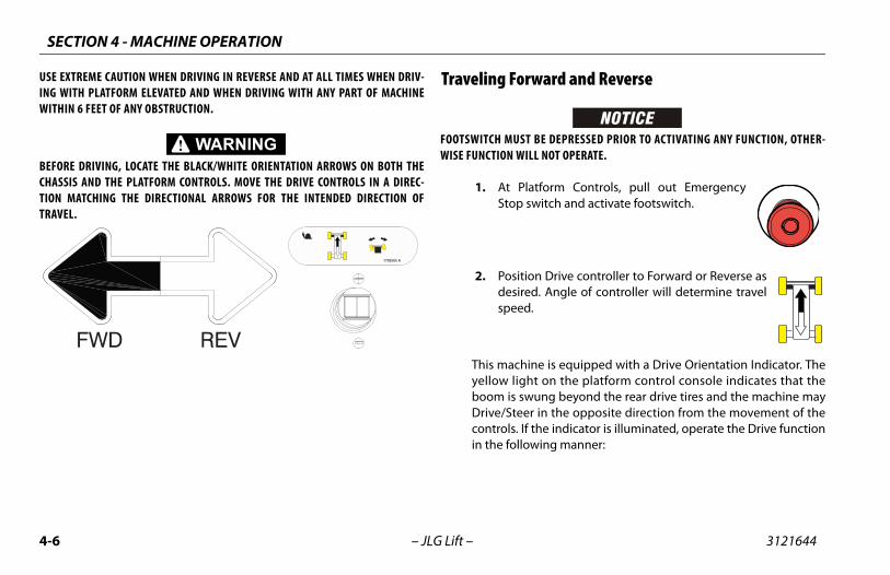
e is equipped with a Drive Orientation Indicator. Thet on the platform control console indicates that theung beyond the rear drive tires and the machine may in the opposite direction from the movement of thehe indicator is illuminated, operate the Drive functioning manner:
– JLG Lift –
EXTREME CAUTION WHEN DRIVING IN REVERSE AND AT ALL TIMES WHEN DRIV-ITH PLATFORM ELEVATED AND WHEN DRIVING WITH ANY PART OF MACHINE
IN 6 FEET OF ANY OBSTRUCTION.
RE DRIVING, LOCATE THE BLACK/WHITE ORIENTATION ARROWS ON BOTH THESIS AND THE PLATFORM CONTROLS. MOVE THE DRIVE CONTROLS IN A DIREC- MATCHING THE DIRECTIONAL ARROWS FOR THE INTENDED DIRECTION OFEL.
Traveling Forw
FOOTSWITCH MUST WISE FUNCTION WIL
1. At PlaStop sw
2. Positiodesiredspeed.
This machinyellow lighboom is swDrive/Steercontrols. If tin the follow

SECTION 4 - MACHINE OPERATION
4-7
pes
3121644 – JLG Lift –
Figure 4-3. Grade and Side Slo

SECTION 4 - MACHINE OPERATION
4-8 3121644
4.5
RM
Ground Leveln chassis on a smooth, firm and level surface.
load (personnel, tools and supplies) is 500 LB. (227 kgI markets and 230 kg for CE and Australia markets) or
stribute load uniformly on platform floor and proceedk position.
Positions Above Ground Leveling weight to platform above ground level:
ine what the total weight will be after additional is loaded (personnel, tools and supplies).
weight in platform will be 500 LBS. (227 kg for ANSIs and 230 kg for CE and Australia markets) or less,d with adding weight.
– JLG Lift –
1. Match the black and white direction arrows on both platform con-trol panel and the chas-sis to determine the direction the machine will travel.
2. Push and release the Drive Orientation Over-ride switch. Within 3 seconds, slowly move the Drive control toward the arrow matching the intended direction of machine travel. The indicator light will flash during the 3 second interval until the drive function is selected.
STEERINGDepress footswitch, position thumb switch onDrive/Steer controller to Right for steering right, orto Left for steering left.
4.6 PLATFO
Loading From1. Positio
2. If totalfor ANSless, dito wor
Loading FromBefore load
1. Determweight
2. If totalmarketprocee
SECTION 4 - MACHINE OPERATION
4-9
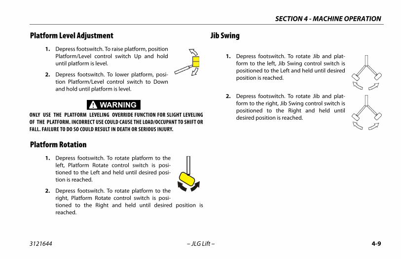
press footswitch. To rotate Jib and plat-rm to the left, Jib Swing control switch issitioned to the Left and held until desiredsition is reached.
press footswitch. To rotate Jib and plat-rm to the right, Jib Swing control switch issitioned to the Right and held untilsired position is reached.
3121644 – JLG Lift –
Platform Level Adjustment1. Depress footswitch. To raise platform, position
Platform/Level control switch Up and holduntil platform is level.
2. Depress footswitch. To lower platform, posi-tion Platform/Level control switch to Downand hold until platform is level.
ONLY USE THE PLATFORM LEVELING OVERRIDE FUNCTION FOR SLIGHT LEVELINGOF THE PLATFORM. INCORRECT USE COULD CAUSE THE LOAD/OCCUPANT TO SHIFT ORFALL. FAILURE TO DO SO COULD RESULT IN DEATH OR SERIOUS INJURY.
Platform Rotation1. Depress footswitch. To rotate platform to the
left, Platform Rotate control switch is posi-tioned to the Left and held until desired posi-tion is reached.
2. Depress footswitch. To rotate platform to theright, Platform Rotate control switch is posi-tioned to the Right and held until desired position isreached.
Jib Swing
1. Defopopo
2. Defopode

SECTION 4 - MACHINE OPERATION
4-1 3121644
4.7
A REDWHICSLOPLIGH
DO NCHASGREAHORI
TO AABOVMACH
TRAVEXCE
TO AVTOGG‘OFF’
TO ASWITGENC
Boomoom, with footswitch activated, posi-control switch to Right or Left for direc-.
E BOOM MAKE SURE THERE IS AMPLE ROOM FOR THE BOOM TOG WALLS, PARTITIONS AND EQUIPMENT.
wering the Lower and Mid Boomlower the Lower and Mid Boom,
itch activated, position Loweritch to Up or Down as desired.
wering the Upper Boomwer the Upper Boom, with footswitch
osition Upper Boom Lift switch to Uptil desired height is reached.
0 – JLG Lift –
BOOM
TILT WARNING LIGHT IS LOCATED ON THE CONTROL CONSOLEH LIGHTS WHEN THE CHASSIS IS ON A 5 DEGREE OR GREATERE. DO NOT SWING OR RAISE BOOM ABOVE HORIZONTAL WHENT IS LIT OR AUDIBLE ALARM SOUNDS.
OT DEPEND ON TILT ALARM AS A LEVEL INDICATOR FOR THESIS. TILT ALARM INDICATES CHASSIS IS ON A SEVERE SLOPE (5 DEGREE ORTER). CHASSIS MUST BE LEVEL BEFORE SWINGING, OR RAISING BOOM ABOVEZONTAL.
VOID TIP OVER IF RED TILT WARNING LIGHT LIGHTS WHEN BOOM IS RAISEDE HORIZONTAL, LOWER PLATFORM TO GROUND LEVEL. THEN REPOSITIONINE SO THAT CHASSIS IS LEVEL BEFORE RAISING BOOM.
ELING WITH BOOM BELOW HORIZONTAL IS PERMITTED ON GRADES NOTEDING THOSE SPECIFIED ON THE SERIAL NUMBER PLATE.
OID SERIOUS INJURY, DO NOT OPERATE MACHINERY IF ANY CONTROL LEVER ORLE SWITCH CONTROLLING PLATFORM MOVEMENT DOES NOT RETURN TO THE OR NEUTRAL POSITION WHEN RELEASED.
VOID A COLLISION AND INJURY IF PLATFORM DOES NOT STOP WHEN A CONTROLCH OR LEVER IS RELEASED, REMOVE FOOT FROM FOOTSWITCH OR USE EMER-Y STOP SWITCH TO STOP THE MACHINE.
Swinging the To swing btion Swing tion desired
WHEN SWINGING THCLEAR SURROUNDIN
Raising and LoTo raise or with footswBoom Lift sw
Raising and LoTo raise or loactivated, por Down un

SECTION 4 - MACHINE OPERATION
4-11
nly Operating Modechine will operate in the battery only mode when the fol-
two conditions apply:
ound Control Emergency Stop Switch islled out (on), and:
e switch on the platform control console is the Off or Disable position.
mode the machine will operate as a conventional batteryed unit. The batteries can be used until they are fully dis-d.
3121644 – JLG Lift –
4.8 GENERATOR
The machine is equipped with an engine powered DC generatorconnected in parallel to the 48V DC battery bank.
Automatic Operating ModeThe generator will operate in automatic mode always when thefollowing two conditions apply.
1. Ground Control Emergency Stop Switch ispulled out (on), and:
2. The Generator Enable switch on the platformcontrol console is in the On or Enable position.
When the above conditions apply, the generator’scontroller will monitor status of the batteries, will turn on auto-matically when the battery voltage drops as a result of dischargeand will turn off when batteries are fully charged.
Battery OThe malowing
1. Grpu
2. Thin
In this operatcharge

SECTION 4 - MACHINE OPERATION
4-1 3121644
Ma ERr converts 48 VDC to 110 VAC to allow operation of from the machine’s batteries.
rter is operational when the emergency stop switch ist.
hine and inverter can be operated at the same time.
rter will shut off at approximately 42 VDC and stay off emergency stop switch is recycled. It will operatetil voltage drops to 42 VDC.
hine will operate down to 36 VDC.
rter will shut down if the high temperature light indi-erheating. It will automatically turn back on when
load light indicates an output wiring short circuit or a is too large for the rating of the inverter.
E FUNCTION SPEEDSn Speed Control affects the speed of boom functionsTelescope, and Rotate. Turn the control clockwise tonction speed or counterclockwise to decrease func-When in the counterclockwise maximum position, alle placed in creep speed.
2 – JLG Lift –
nual (Charge) Operating ModeThe generator will operate in manual mode always when the fol-lowing three conditions apply.
1. Ground Control Emergency Stop Switch ispulled out (on), and:
2. The switch on the platform control console isin the On or Enable position and:
3. The Manual Charge push button is activated.
Activation of the Manual Charge button will start the engine andinitiate the charging cycle even if the batteries are charged abovethe level of automatic start. The operator can initiate the chargecycle to charge the batteries to the maximum level. The chargingcycle will include finishing phase similar to conventional char-gers.
4.9 INVERTThe invertepower tools
• The invepulled ou
• The mac
• The inveuntil theagain un
• The mac
• The invecated ovcooled.
• The overload that
4.10 MACHINThe FunctioLower Lift, increase fution speed. functions ar

SECTION 4 - MACHINE OPERATION
4-13
GUARD OPERATIONrd is used to provide enhanced control panel protection.
the SkyGuard sensor is activated, functions that were in the time of actuation will reverse or cutout. The tableoutlines these functions.
Table 4-1. Skyguard Function Table
SwingDrive
ForwardDrive
ReversePlatform
LevelPlatform
RotateJibLift
JibRotate
JibTele
R R I R R C C C C C
rsal is Activated
ut is Activated
d
uch is enabled with SkyGuard all functions are cut out only.
plies to Main Tele Out. Main Tele In would be cut out
3121644 – JLG Lift –
4.11 MACHINE SAFETY SYSTEM OVERRIDE (MSSO)(CE ONLY)
The Machine Safety System Override (MSSO) isused to override function controls for EmergencyPlatform Retrieval only. Refer to Section 5.7,Machine Safety System Override (MSSO)(CEOnly)for operating procedures.
4.12 SKYSkyguaWhen use atbelow
MainLift
MainTele
R C/R*
R = Indicates Reve
C = Indicates Cuto
I = Input is Ignore
Note: When Soft To
* Reversal only ap

SECTION 4 - MACHINE OPERATION
4-1 3121644
4.1
NOT
OWN AND PARK
rking battery powered units overnight, batteries shouldged in accordance with instructions in Section 2 toeadiness for following workday.
machines are equipped with a static strap due to staticty build-ups. Strap is located under rear of machine chas-
n and park the machine, the procedures are as fol-
achine to a reasonably well protected area.
boom is lowered over rear drive axle.
own Emergency Stop at Platform Controls.
own Emergency Stop at Ground Controls. Positionm/Ground Select switch to center OFF.
ssary, cover Platform Controls to protect instructions, warning decals and operating controls from hostilement.
4 – JLG Lift –
3 BOOM SYNCHRONIZING PROCEDURE
E: If the Lower Boom assembly does not fully lower:
1. Remove all personnel from the platform.
2. Pull the red knob located beside the main control valve.
3. From Ground Control, activate the lift control switch, raiseLower Boom 1.8 m (6 feet).
4. After raising Lower Boom, release the red knob.
5. Activate Lower Boom Down, fully lower boom.
6. Repeat step 1 thru 5 if necessary.
4.14 SHUT D
NOTE: When pabe charensure r
NOTE: Electric electricisis.
To shut dowlows:
1. Drive m
2. Ensure
3. Shut d
4. Shut dPlatfor
5. If neceplacardenviron

SECTION 4 - MACHINE OPERATION
4-15
ace the boom in the stowed position.
move all loose items from the machine.
cure the chassis and the platform using straps or chains ofequate strength.
3121644 – JLG Lift –
4.15 MACHINE LIFTING AND TIE DOWNSee Figure 4-4.
Lifting1. Refer to the Serial Number Plate, refer to the Specifica-
tions section of this manual, or weigh the individual unitto find out the Gross Vehicle Weight.
2. Place the boom in the stowed position.
3. Remove all loose items from the machine.
4. Attach lifting device and equipment only to the desig-nated lifting points.
5. Properly adjust the rigging to prevent damage to themachine and so the machine remains level.
Tie Down1. Pl
2. Re
3. Sead
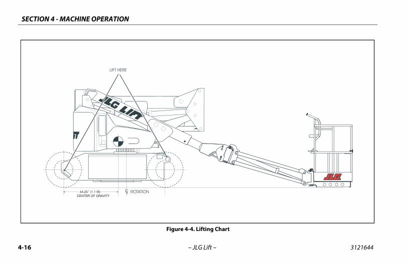
SECTION 4 - MACHINE OPERATION
4-1 3121644
6 – JLG Lift –Figure 4-4. Lifting Chart

SECTION 4 - MACHINE OPERATION
4-17
of 3
3121644 – JLG Lift –
Figure 4-5. Decal Installation - Sheet 1

SECTION 4 - MACHINE OPERATION
4-1 3121644
8 – JLG Lift –Figure 4-6. Decal Installation - Sheet 2 of 3

SECTION 4 - MACHINE OPERATION
4-19
of 3
3121644 – JLG Lift –
Figure 4-7. Decal Installation - Sheet 3

SECTION 4 - MACHINE OPERATION
4-2 3121644
nd
Eng/CSA French
0259495-17
Chinese/Eng
0259540-14
Spa/Portuguese0259499-16
- - - - - -
1703936 1703937 1703940
- - - - - -
1703930 1703931 1703934
1705514 - - - -
- - - - - -
1706948 1706948 1706948
- - - - - -
1701504 1701504 1701504
1701642 1701642 1701642
1703924 1703925 1703928
- - - - - -
1701644 1701644 1701644
- - - - - -
0 – JLG Lift –
Table 4-2. E400A/E400AJP Decal Lege
Item # ANSI0259301-B
CE/AusI0275070-7
Japanese0259536-B
Korean0259538-14
Eng/Lat. Spanish0259497-17
1 - - - - - - - - - -
2 1703805 - - 1703938 1703939 1703935
3 - - - - - - - - - -
4 1703798 1705822 1703932 1703933 1703929
5 - - - - - - - - - -
6 1001131269 - - - - - - - -
7 1706948 - - 1706948 1706948 1706948
8 - - - - - - - - - -
9 1701504 1701504 1701504 1701504 1701504
10 1701642 1701642 1701642 1701642 1701642
11 1703797 1705921 1703926 1703927 1703923
12 - - - - - - - - - -
13 1701644 1701644 1701644 1701644 1001104864
14 - - - - - - - - - -

SECTION 4 - MACHINE OPERATION
4-21
83 1703984 1703982 1703985
77 1704277 1704277 1704277
1704006 - - 1704008
- - - - - -
- - - - - -
43 3251243 - - 3251243
- - - - - -
91 1701691 1701691 1701691
864 1001104864 1001104864 1001104864
01 1704000 - - 1704002
54 1704254 1704254 1704254
53 1704253 - - 1704253
54 1704452 1704419 1704453
31 1704431 1704431 1704431
egend
/nish7-17
Eng/CSA French
0259495-17
Chinese/Eng
0259540-14
Spa/Portuguese0259499-16
3121644 – JLG Lift –
15 - - 1705828 1703980 1703981 17039
16 1704277 1704277 1704277 1704277 17042
17 - - - - - - - - - -
18 - - - - - - - - - -
19 - - - - - - - - - -
20 - - - - - - - - 32512
21 - - - - - - - - - -
22 1701691 1701691 1701691 1701691 17016
23 1001104864 1001104864 1001104864 1001104864 1001104
24 1702868 - - - - - - 17040
25 1704254 1704254 1704254 1704254 17042
26 1704253 - - 1704253 - - 17042
27 1704446 1706378 1704417 1704418 17044
28 1704431 1704431 1704431 1704431 17044
Table 4-2. E400A/E400AJP Decal L
Item # ANSI0259301-B
CE/AusI0275070-7
Japanese0259536-B
Korean0259538-14
EngLat. Spa025949

SECTION 4 - MACHINE OPERATION
4-2 3121644
- - - - - -
- - - - - -
- - - - - -
- - - - - -
- - - - - -
- - - - - -
- - - - - -
- - - - - -
1701500 1701500 1701500
1701509 1701509 1701509
1704340 1704344 1704341
- - - - - -
1703948 1703949 1703952
- - - - - -
nd
Eng/CSA French
0259495-17
Chinese/Eng
0259540-14
Spa/Portuguese0259499-16
2 – JLG Lift –
29 - - - - - - - - - -
30 - - - - - - - - - -
31 - - - - - - - - - -
32 - - - - - - - - - -
33 - - - - - - - - - -
34 - - - - - - - - - -
35 - - - - - - - - - -
36 - - - - - - - - - -
37 1701500 1703811 1701500 1701500 1701500
38 1701509 1701509 1701509 1701509 1701509
39 1703813 1705670 1704342 1704343 1704339
40 3252347 - - - - - - - -
41 1703804 1701518 1703950 1703951 1703947
42 - - - - - - - - - -
Table 4-2. E400A/E400AJP Decal Lege
Item # ANSI0259301-B
CE/AusI0275070-7
Japanese0259536-B
Korean0259538-14
Eng/Lat. Spanish0259497-17

SECTION 4 - MACHINE OPERATION
4-23
- - - - - -
- - - - - -
- - - - - -
- - - - - -
65 1702265 1703988 1703991
- - - - - -
- - - - - -
00 1702300 1702300 1702300
- - - - - -
- - 1702631 1702631
818 1001121816 1001121823 1001121923
- - - - - -
- - - - - -
- - - - - -
egend
/nish7-17
Eng/CSA French
0259495-17
Chinese/Eng
0259540-14
Spa/Portuguese0259499-16
3121644 – JLG Lift –
43 - - - - - - - - - -
44 - - - - - - - - - -
45 - - - - - - - - - -
46 - - - - - - - - - -
47 1702265 1705977 1702271 1703987 17022
48 - - - - - - - - - -
49 - - - - - - - - - -
50 1702300 1703814 1702300 1702300 17023
51 - - - - - - - - - -
52 - - - - 1702631 1702631 - -
53 1001121814 1705978 1001121821 1001121921 1001121
54 - - - - - - - - - -
55 - - - - - - - - - -
56 - - - - - - - - - -
Table 4-2. E400A/E400AJP Decal L
Item # ANSI0259301-B
CE/AusI0275070-7
Japanese0259536-B
Korean0259538-14
EngLat. Spa025949

SECTION 4 - MACHINE OPERATION
4-2 3121644
- - - - - -
- - - - - -
- - - - - -
- - - - - -
- - - - - -
- - - - - -
- - - - - -
1704252 - - 1706950
1001121803 1001121810 1001121920
1701502 1701502 1701502
1701503 1701503 1701503
- - - - - -
- - - - - -
- - - - - -
nd
Eng/CSA French
0259495-17
Chinese/Eng
0259540-14
Spa/Portuguese0259499-16
4 – JLG Lift –
57 - - - - - - - - - -
58 - - - - - - - - - -
59 - - - - - - - - - -
60 - - - - - - - - - -
61 - - - - - - - - - -
62 - - - - - - - - - -
63 - - - - - - - - - -
64 1706950 - - - - - - 1706950
65 1001121801 1705978 1001121808 1001121918 1001121805
66 1701502 1701502 1701502 1701502 1701502
67 1701503 1701503 1701503 1701503 1701503
68 - - - - - - - - - -
69 - - - - - - - - - -
70 - - - - - - - - - -
Table 4-2. E400A/E400AJP Decal Lege
Item # ANSI0259301-B
CE/AusI0275070-7
Japanese0259536-B
Korean0259538-14
Eng/Lat. Spanish0259497-17

SECTION 4 - MACHINE OPERATION
4-25
- - - - - -
- - - - - -
- - - - - -
- - - - - -
- - - - - -
- - - - - -
12 1704412 1704412 1704412
- - - - - -
85 1704885 1704885 1704885
- - - - - -
10 1705429 1705430 1001113680
egend
/nish7-17
Eng/CSA French
0259495-17
Chinese/Eng
0259540-14
Spa/Portuguese0259499-16
3121644 – JLG Lift –
71 - - - - - - - - - -
72 - - - - - - - - - -
73 - - - - - - - - - -
74 - - - - - - - - - -
75 - - - - - - - - - -
76 - - - - - - - - - -
77 1704412 1704412 1704412 1704412 17044
78 1704830 - - - - - - - -
79 1704885 1704885 1704885 1704885 17048
80 - - - - - - - - - -
81 1705351 - - 1705426 1705427 17059
Table 4-2. E400A/E400AJP Decal L
Item # ANSI0259301-B
CE/AusI0275070-7
Japanese0259536-B
Korean0259538-14
EngLat. Spa025949

SECTION 4 - MACHINE OPERATION
4-2 3121644
Eng/French
0259494-21
Chinese0259539-17
Spa/Portuguese0259498-19
- - - - - -
1703936 1703937 1703940
- - - - - -
1703930 1703931 1703934
1705514 - - - -
- - - - - -
1706948 1706948 1706948
- - - - - -
1701504 1701504 1701504
1701642 1701642 1701642
1703924 1703925 1703928
- - - - - -
1701644 1701644 1701644
- - - - - -
1703984 1703982 1703985
1704277 1704277 1704277
1704006 - - 1704008
6 – JLG Lift –
Table 4-3. M400AJP Decal Legend
Item # ANSI0258973-B
CE/AusI0275069-8
Japanese0259535-17
Korean0259537-B
Eng/Spanish
0259496-21
1 - - - - - - - - - -
2 1703805 - - 1703938 1703939 1703935
3 - - - - - - - - - -
4 1703798 1705822 1703932 1703933 1703929
5 - - - - - - - - - -
6 1700584 - - - - - - - -
7 1706948 - - 1706948 1706948 1706948
8 - - - - - - - - - -
9 1701504 1701504 1701504 1701504 1701504
10 1701642 1701642 1701642 1701642 1701642
11 1703797 1705921 1703926 1703927 1703923
12 - - - - - - - - - -
13 1701644 1701644 1701644 1701644 1701644
14 - - - - - - - - - -
15 - - 1705828 1703980 1703981 1703983
16 1704277 1704277 1704277 1704277 1704277
17 - - - - - - - - - -
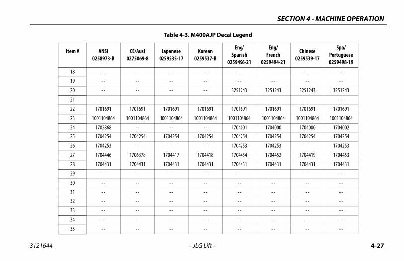
SECTION 4 - MACHINE OPERATION
4-27
- - - - - -
- - - - - -
43 3251243 3251243 3251243
- - - - - -
91 1701691 1701691 1701691
864 1001104864 1001104864 1001104864
01 1704000 1704000 1704002
54 1704254 1704254 1704254
53 1704253 - - 1704253
54 1704452 1704419 1704453
31 1704431 1704431 1704431
- - - - - -
- - - - - -
- - - - - -
- - - - - -
- - - - - -
- - - - - -
- - - - - -
end
/sh6-21
Eng/French
0259494-21
Chinese0259539-17
Spa/Portuguese0259498-19
3121644 – JLG Lift –
18 - - - - - - - - - -
19 - - - - - - - - - -
20 - - - - - - - - 32512
21 - - - - - - - - - -
22 1701691 1701691 1701691 1701691 17016
23 1001104864 1001104864 1001104864 1001104864 1001104
24 1702868 - - - - - - 17040
25 1704254 1704254 1704254 1704254 17042
26 1704253 - - - - - - 17042
27 1704446 1706378 1704417 1704418 17044
28 1704431 1704431 1704431 1704431 17044
29 - - - - - - - - - -
30 - - - - - - - - - -
31 - - - - - - - - - -
32 - - - - - - - - - -
33 - - - - - - - - - -
34 - - - - - - - - - -
35 - - - - - - - - - -
Table 4-3. M400AJP Decal Leg
Item # ANSI0258973-B
CE/AusI0275069-8
Japanese0259535-17
Korean0259537-B
EngSpani
025949

SECTION 4 - MACHINE OPERATION
4-2 3121644
- - - - - -
1701500 1701500 1701500
1701509 1701509 1701509
1704340 1704344 1704341
- - - - - -
1703948 1703949 1703952
- - - - - -
- - - - - -
- - - - - -
- - - - - -
- - - - - -
1702265 1703988 1703991
- - - - - -
- - - - - -
1702300 1702300 1702300
- - - - - -
- - - - - -
1707047 1001121823 1001121923
Eng/French
0259494-21
Chinese0259539-17
Spa/Portuguese0259498-19
8 – JLG Lift –
36 - - - - - - - - - -
37 1701500 1703811 1701500 1701500 1701500
38 1701509 1701509 1701509 1701509 1701509
39 1703813 1705670 1704342 1704343 1704339
40 3252347 - - - - - - - -
41 1703804 1701518 1703950 1703951 1703947
42 - - - - - - - - - -
43 - - - - - - - - - -
44 - - - - - - - - - -
45 - - - - - - - - - -
46 - - - - - - - - - -
47 1702265 1705977 1702271 1703987 1702265
48 - - - - - - - - - -
49 - - - - - - - - - -
50 1702300 1703814 1702300 1702300 1702300
51 - - - - - - - - - -
52 1702631 - - - - - - - -
53 1001121814 1705978 1001121854 1001121921 1001121818
Table 4-3. M400AJP Decal Legend
Item # ANSI0258973-B
CE/AusI0275069-8
Japanese0259535-17
Korean0259537-B
Eng/Spanish
0259496-21

SECTION 4 - MACHINE OPERATION
4-29
- - - - - -
- - - - - -
- - - - - -
- - - - - -
- - - - - -
- - - - - -
- - - - - -
- - - - - -
- - - - - -
- - - - - -
50 1706950 - - 1706950
805 1707055 1001121810 1001121920
02 1701502 1701502 1701502
03 1701503 1701503 1701503
- - - - - -
- - - - - -
71 1001093687 1001093687 1001093687
- - - - - -
end
/sh6-21
Eng/French
0259494-21
Chinese0259539-17
Spa/Portuguese0259498-19
3121644 – JLG Lift –
54 - - - - - - - - - -
55 - - - - - - - - - -
56 - - - - - - - - - -
57 - - - - - - - - - -
58 - - - - - - - - - -
59 - - - - - - - - - -
60 - - - - - - - - - -
61 - - - - - - - - - -
62 - - - - - - - - - -
63 - - - - - - - - - -
64 1706950 - - - - - - 17069
65 1001121801 1705978 1001121808 1707058 1001121
66 1701502 1701502 1701502 1701502 17015
67 1701503 1701503 1701503 1701503 17015
68 - - - - - - - - - -
69 - - - - - - - - - -
70 1704286 - - 1001093687 1001093687 17043
71 - - - - - - - - - -
Table 4-3. M400AJP Decal Leg
Item # ANSI0258973-B
CE/AusI0275069-8
Japanese0259535-17
Korean0259537-B
EngSpani
025949
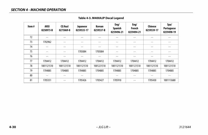
SECTION 4 - MACHINE OPERATION
4-3 3121644
- - - - - -
- - - - - -
- - - - - -
- - - - - -
- - - - - -
1704412 1704412 1704412
1001121510 1001121510 1001121510
1704885 1704885 1704885
- - - - - -
- - 1705430 1001113680
Eng/French
0259494-21
Chinese0259539-17
Spa/Portuguese0259498-19
0 – JLG Lift –
72 - - - - - - - - - -
73 1702962 - - - - - - - -
74 - - - - - - - - - -
75 - - - - 1705084 1705084 - -
76 - - - - - - - - - -
77 1704412 1704412 1704412 1704412 1704412
78 1001121510 1001121510 1001121510 1001221510 1001121510
79 1704885 1704885 1704885 1704885 1704885
80 - - - - - - - -
81 1705351 - - 1705426 1705427 1705910
Table 4-3. M400AJP Decal Legend
Item # ANSI0258973-B
CE/AusI0275069-8
Japanese0259535-17
Korean0259537-B
Eng/Spanish
0259496-21

SECTION 5 - EMERGENCY PROCEDURES
5-1
OCEDURES
NY ACCIDENT, THOROUGHLY INSPECT THE MACHINE AND TEST ALLST FROM THE GROUND CONTROLS, THEN FROM THE PLATFORM CON-
LIFT ABOVE 3 M (10 FT.) UNTIL YOU ARE SURE THAT ALL DAMAGE HASD, IF REQUIRED, AND THAT ALL CONTROLS ARE OPERATING COR-
ERGENCY OPERATION
nable to Control MachinePLATFORM OPERATOR IS PINNED, TRAPPED OR UNABLE TOTE OR CONTROL MACHINE:
ther personnel should operate the machine from groundntrols only as required.
ther qualified personnel on the platform may use the plat-rm controls. DO NOT CONTINUE OPERATION IF CONTROLS
NOT FUNCTION PROPERLY.
anes, forklift trucks or other equipment can be used tomove platform occupants and stabilize motion of theachine.
3121644 – JLG Lift –
SECTION 5. EMERGENC Y PR
5.1 GENERALThis section explains the steps to be taken in case of an emer-gency situation while operating.
5.2 INCIDENT NOTIFICATIONJLG Industries, Inc. must be notified immediately of any incidentinvolving a JLG product. Even if no injury or property damage isevident, the factory should be contacted by telephone and pro-vided with all necessary details.
In USA:JLG Phone: 877-JLG-SAFE (554-7233) (8am till 4:45pm EST)
Outside USA: 240-420-2661
E-mail:
Failure to notify the manufacturer of an incident involving a JLGIndustries product within 48 hours of such an occurrence mayvoid any warranty consideration on that particular machine.
FOLLOWING AFUNCTIONS FIRTROLS. DO NOTBEEN REPAIRERECTLY.
5.3 EM
Operator UIF THE OPERA
1. Oco
2. OfoDO
3. Crrem

SECTION 5 - EMERGENCY PROCEDURES
5-2 3121644
Pla
5.4
L DESCENT SYSTEM
scent system is used, in the event of total power fail-e upper and lower booms using gravity. To operatecent system, proceed as follows:
manual descent knob on main valve and turn clock-nstall handle into manual descent pump and lower
and Lower Booms by pumping the handle until theypletely lowered.
anual descent knob counterclockwise and lower the(or main) Boom by pumping the handle until it istely lowered. Return manual descent knob to center
n and stow handle in bracket provided.
L SWING OVERRIDE
ing override is used to manually swing boom andbly in the event of a total power failure when the
itioned over a structure or obstacle. To operate theverride, proceed as follows:
a 7/8 inch socket and ratchet wrench, locate nut onworm gear on left side of machine.
wrench on nut and ratchet in the direction desired.
– JLG Lift –
tform or Boom Caught OverheadIf the platform or boom becomes jammed or snagged in over-head structures or equipment, rescue platform occupants prior tofreeing the machine.
EMERGENCY TOWING PROCEDURESTowing this machine is prohibited, unless properly equipped.However, provisions for moving the machine, in case of a mal-function or power failure, have been incorporated. The followingprocedures are to be used ONLY for emergency movement to asuitable maintenance area.
1. Chock wheels securely.
2. Disengage drive hubs by reversing disconnect caps.
3. Connect suitable equipment, remove chocks, and movemachine.
After moving machine, complete the following procedures:
1. Position machine on a firm and level surface.
2. Chock wheels securely.
3. Engage drive hubs by reversing disconnect caps on hubs.
4. Remove chocks from wheels as needed.
5.5 MANUA
The manual deure, to lower ththe manual des
1. Locatewise. Ithe Midare com
2. Turn mUpper complepositio
5.6 MANUA
The manual swturntable assemplatform is posmanual swing o
1. Using swing
2. Install

SECTION 5 - EMERGENCY PROCEDURES
5-3
3121644 – JLG Lift –5.7 MACHINE SAFETY SYSTEM OVERRIDE (MSSO)(CE ONLY)
The Machine Safety System Override (MSSO) isonly to be used to retrieve an operator that ispinned, trapped, or unable to operate themachine and function controls are locked outfrom the platform due to a platform overload sit-uation.
NOTE: If the MSSO functionality is used, the fault indicator will flashand a fault code is set in the JLG Control System which must bereset by a qualified JLG Service Technician.
NOTE: No functional checks of the MSSO system are necessary. The JLGControl system will set a Diagnostic Trouble Code if the controlswitch is faulty.
To operate the MSSO:
1. From the ground control console, place the Platform/Ground Select switch in the Ground position.
2. Pull out the Power/Emergency Stop control.
3. Start the engine.
4. Press and hold the MSSO switch and the control switch for the desired function.

SECTION 5 - EMERGENCY PROCEDURES
5-4 3121644
– JLG Lift –NOTES:

PECIFICATIONS & OPERATOR MAINTENANCE
6-1
PERATOR MAINTENANCE
RATING SPECIFICATIONS
Table 6-1. Operating Specifications
Load (Capacity)
500 lb. (227 kg)
Load (Capacity)arkets
500 lb. (230 kg)
l Grade, Stowed Position 2 W/D-30%
l Grade, Stowed Position 5 degrees
: 40 ft. (12.19 m)
rm Reach (Up & Over)
M400AJPn21 ft.-2 in. (6.41 m.)
22 ft.-5 in.(6.8 m.)
0AJPn5 ft.-9 in. (1.75 m.)
4 ft.-11 in. (1.50 m.)
Outside) 10 ft.-4 in. (3.15 m.)
SECTION 6 - GENERAL S
3121644 – JLG Lift –
SECTION 6. GENERAL SPECIFICATIONS & O
6.1 INTRODUCTIONThis section of the manual provides additional necessary infor-mation to the operator for proper operation and maintenance ofthis machine.
The maintenance portion of this section is intended as informa-tion to assist the machine operator to perform daily maintenancetasks only, and does not replace the more thorough PreventiveMaintenance and Inspection Schedule included in the Serviceand Maintenance Manual.
Other Publications Available:
Service and Maintenance Manual - ANSI, CSA Spec...........3121645
Illustrated Parts Manual ................................................................3121646
6.2 OPE
Maximum Work ANSI Markets Unrestricted:
Maximum Work CE & Australia M Unrestricted:
Maximum Trave (Gradeability)
Maximum Trave (Side Slope)
Platform Height
Horizontal Platfo E400An E/M400AJP; E/
Machine Width: E/M400AJP E400An; E/M40
Turning Radius (

SECTION 6 - GENERAL SPECIFICATIONS & OPERATOR MAINTENANCE
6-2 3121644
Turn E/M E40
Max E 4 E/M E/M
Grou
E 4
E/M
E/M
Driv E/M
E40
Gros E40 E40 M4 E40 M4
Max
7 hours continuous
17 hours from full discharge6.2 hours
yd. Pressure 3400 psi(234 bar)
able 6-1. Operating Specifications
– JLG Lift –
ing Radius (Inside)400AJP0An; E/M400AJPn
2 ft.-0 in. (0.61 m.)2 ft.- 10 in. (0.86 m.)
imum Tire Load: 00Anarrow
400AJP400AJPnarrow
4700 lbs. (2132 kg)6260 lbs. (2840 kg)7160 lbs. (3248 kg)
nd Bearing Pressure
00Anarrow
400AJP
400AJPnarrow
104 psi (7.3 kg/cm2)
74 psi (5.2 kg/cm2)
185 psi (13.0 kg/cm2)
e Speed: (Above Horz.)400AJP
0An; E/M400AJPn
42-44 sec / 200 ft.50-53 sec / 50 ft.
45-50 sec / 200 ft.55-68 sec / 50 ft.
s Machine Weight 0An0AJP00AJP0AJPn00AJPn
13100 lb. (5942 kg.)13700 lb. (6214 kg.)13930 lb. (6319 kg.)14900 lb. (6759 kg.)15130 lb. (6863 kg.)
imum System Voltage 48 VDC
Table 6-1. Operating Specifications
Battery Life per Charge
Battery Recharge Time Charger Generator
Maximum Main Relief H
T

PECIFICATIONS & OPERATOR MAINTENANCE
6-3
Table 6-3. Tire Specifications
Type PressurePly
RatingLoad Range
Pneumatic 90 psi (6 Bar) 10 E
Foam-Filled N/A 10 E
Pneumatic 95 psi (6.5 Bar) 10 E
Non-Marking N/A N/A N/A
Non-Marking N/A N/A N/A
Non-Marking N/A N/A N/A
SECTION 6 - GENERAL S
3121644 – JLG Lift –
Capacities TiresTable 6-2. Capacities
Generator Fuel Tank 4 Gallons (15.1 L)
Hydraulic Oil Tank E400An E/M400AJP, E/M400AJPn
4 gallons. (15.1L)5 Gallons (19 L) w/ 10% air space
Hydraulic System (Including Tank) 9 Gallons (34.1 L)
Torque Hub, Drive* 17 ounces (0.50 L)
*Torque hubs should be one half full of lubricant.
Size
IN240/55-17.5
IN240/55-17.5
LT215/8R16
26 x 7 x 20
25 x 7 x 12
22 x 6 x 17.5

SECTION 6 - GENERAL SPECIFICATIONS & OPERATOR MAINTENANCE
6-4 3121644
Dim
ications
0AJPn5 ft. 0 in. (1.51 m)4 ft. 3.75 in.(1.31 m)
sition)00AJPnarrow 0
4 in. (10 cm)
0AJPn8.5 in. (0.22 m)5 in. (0.13 m)
Table 6-5. Torque Requirements
on Torque Value Interval Hours
gs 170 ft. lbs. (230 Nm) 150
(Loctite) 190 ft. lbs.(260Nm) 50/600*
ing bolts for security after first 50 hours of operation and every 600
Table 6-4. Dimensional Data
– JLG Lift –
ensional Data
Torque Specif
Table 6-4. Dimensional Data
Machine Length (stowed) E400An E/M400AJP; E/M400AJPn
18 ft. 1 in. (5.50 m)22.0 ft. (6.7 m)
Machine Height (stowed) E/M400AJP E400An; E/M400AJPn
6 ft. 7 in. (2.0 m)6 ft. 5.75 in. (1.31m)
Up and Over Platform Height 21 ft. 5 in. (6.55 m)
Horizontal Reach @ Maximum Up and Over E 400An E/M400AJP, E/M400AJPn
21 ft. 2 in. (6.41 m)22 ft.-5 in. (6.83 m)
Machine Width E/M400AJP E400An; E/M400AJPn
5 ft. 9 in. (1.75 m)4 ft. 11 in. (1.50 m)
Wheel Base 6 ft. 7.0 in. (2.00 m)
Working Height 46 ft. 0 in. (14.02 m)
Platform Height 40 ft. 0 in. (12.19 m)
Track Width E/M400AJP E400An; E/M40
Tail Swing (Any Po E/M400AJP, E/M4 E400Anarrow
Ground Clearance E/M400AJP E 400An, E/M40
Descripti
Wheel Lu
Swing Bearing
* Check swing bearhours thereafter.

PECIFICATIONS & OPERATOR MAINTENANCE
6-5
Table 6-7. Mobil DTE 11M Specs
ISO Viscosity Grade #15
Gravity API 31.9
Pour Point, Max -40°F (-40°C)
Flash Point, Min. 330°F (166°C)
Viscosity
at 40° C 15 cSt
at 100° C 4.1 cSt
at 100° F 80 SUS
at 210° F 43 SUS
cp at -30° F 3.200
Viscosity Index 140
SECTION 6 - GENERAL S
3121644 – JLG Lift –
Hydraulic Oil
NOTE: Hydraulic oils must have anti-wear qualities at least to API Ser-vice Classification GL-3, and sufficient chemical stability formobile hydraulic system service.
Aside from JLG recommendations, it is not advisable to mix oilsof different brands or types, as they may not contain the samerequired additives or be of comparable viscosities. If use ofhydraulic oil other than Mobil DTE 11M is desired, contact JLGIndustries for proper recommendations.
Table 6-6. Hydraulic Oil
Hydraulic System OperatingTemperature Range
S.A.E. ViscosityGrade
+0o to + 180o F(-18o to +83o C 10W
+0o to + 210o F(-18o to +99o C 10W-20, 10W30
+50o to + 210o F(+10o to +99o C 20W-20

SECTION 6 - GENERAL SPECIFICATIONS & OPERATOR MAINTENANCE
6-6 3121644
ity Weights
MS CRITICAL TO STABILITY WITH ITEMS OF DIFFERENT WEIGHTFOR EXAMPLE: BATTERIES, FILLED TIRES, PLATFORM) DO NOT WAY TO AFFECT STABILITY.
able 6-9. Critical Stability Weights
omponent KG. LB.
1746 3850
am-filled) 94 207
2 m]) 41 90
.5 m]) 45 100
54 120
– JLG Lift –
Critical Stabil
DO NOT REPLACE ITEOR SPECIFICATION (MODIFY UNIT IN ANY
Table 6-8. Mobil EAL H Series Specs
Type Synthetic Biodegradable
ISO Viscosity Grade 32
Specific Gravity .950
Pour Point -59°F (-51°C)
Flash Point 514°F (268°C)
Weight 7.64 lb. per gal.(0.9 kg per liter)
Viscosity
at 40° C 33.1 cSt
at 100° C 6.36 cSt
Viscosity Index 147
T
C
Counterweight
Tire & Wheel (fo
Platform (4ft [1.
Platform (5 ft. [1
Battery (each)

PECIFICATIONS & OPERATOR MAINTENANCE
6-7
d of the upper boom, mid boom, and lower boom at ther of the booms.
Figure 6-1. Serial Number Locations
SERIAL NUMBER PLATE
SECTION 6 - GENERAL S
3121644 – JLG Lift –
Serial Number LocationsFor machine identification, a serial number plate is affixed to theleft rear of frame, in front of left rear wheel. If the serial numberplate is damaged or missing, the machine serial number isstamped on the top left side of the frame and the top left side ofthe turntable. In addition, the serial number is stamped on top of
the enleft rea
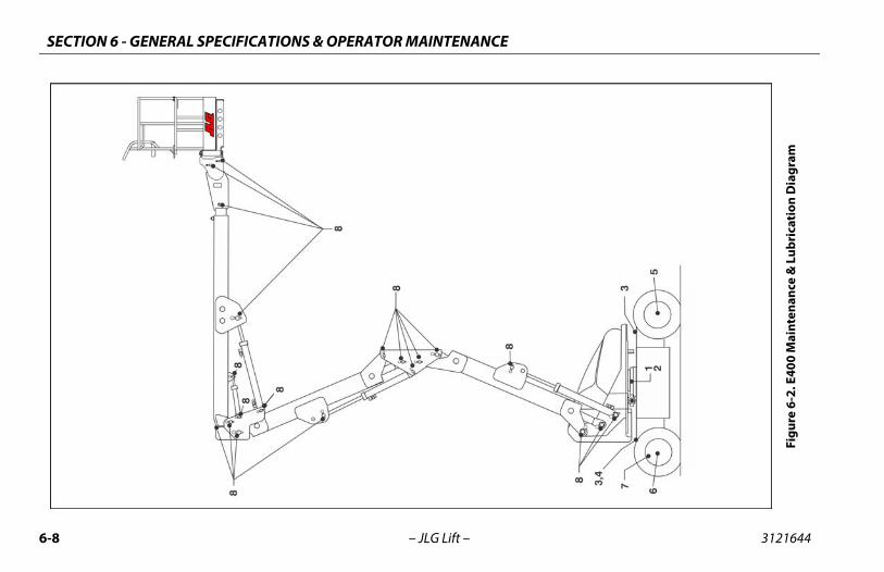
SECTION 6 - GENERAL SPECIFICATIONS & OPERATOR MAINTENANCE
6-8 3121644
Figu
re 6
-2. E
400
Mai
nten
ance
& L
ubri
cati
on D
iagr
am
– JLG Lift –

PECIFICATIONS & OPERATOR MAINTENANCE
6-9
Figu
re 6
-3. M
400
Mai
nten
ance
& L
ubri
cati
on D
iagr
am
SECTION 6 - GENERAL S
3121644 – JLG Lift –

SECTION 6 - GENERAL SPECIFICATIONS & OPERATOR MAINTENANCE
6-1 3121644
6.3
NOT VALS ARE BASED ON MACHINE OPERATION UNDER NORMALACHINES USED IN MULTI-SHIFT OPERATIONS AND/OR EXPOSED
MENTS OR CONDITIONS, LUBRICATION FREQUENCIES MUST BENGLY.
Bearing
nt(s) - 2 Grease Fittings - A/RPG Every 3 months or 150 hrs of operationts - Remote Access (Optional)
0 – JLG Lift –
MAINTENANCE AND LUBRICATION
E: The following numbers correspond to those in Figure 6-2., E400Maintenance & Lubrication Diagram.
LUBRICATION INTERCONDITIONS. FOR MTO HOSTILE ENVIRONINCREASED ACCORDI
1. Swing
Lube PoiCapacityLube - MInterval -Commen
Table 6-10. Lubrication Specifications.
KEY SPECIFICATIONS
MPG Multipurpose Grease having a minimum dripping point of 350 degrees F. Excellent water resistance and adhesive qualities; and being of extreme pressure type (Timken OK 40 pounds minimum).
EPGL Extreme Pressure Gear Lube (oil) meeting API Service Classification GL-5 or Mil-Spec Mil-L-2105.
HO Hydraulic Oil. Mobil DTE-11M
OG* Open Gear Lube - Tribol Molub-Alloy 936 Open Gear Compound. (JLG Part No. 3020027)
BG* Bearing Grease (JLG Part No. 3020029) Mobilith SHA 460.
LL Synthetic Lithium Lubricant, Gredag 741 Grease. (JLG Part No. 3020022)
EO Engine (crankcase) Oil. Gas - API SF/SG class, MIL-L-2104. Diesel - API CC/CD class, MIL-L-2104B/MIL-L-2104C.
*MPG may be substituted for these lubricants, if necessary, but service intervals will be reduced.

PECIFICATIONS & OPERATOR MAINTENANCE
6-11
REASE BEARINGS. OVERGREASING BEARINGS WILL RESULT IN BLOW-L IN HOUSING.
SECTION 6 - GENERAL S
3121644 – JLG Lift –
2. Swing Bearing/Worm Gear Teeth
Lube Point(s) - Grease FittingsCapacity - Spray OnLube - OG or Mobiltac375NCInterval - A/RComments - If necessary install grease fittings into worm gearhousing and grease bearings.
NOTE: OG will allow better cycle times than Mobiltac375NC, howeverMobiltac375NC must be used in dusty environments. If the swingfunction becomes noisy and/or rough lubricate the bearingteeth.
DO NOT OVERGING OUTER SEA

SECTION 6 - GENERAL SPECIFICATIONS & OPERATOR MAINTENANCE
6-1 3121644
nt(s) - Fill Cap - 4 Gal. (15.1 L)
- Check Level daily; Change every 2 years or 1200operation.ts - On new machines, those recently overhauled, ornging hydraulic oil, operate all systems a minimum ofplete cycles and recheck oil level in reservoir.
2 – JLG Lift –
3. Hydraulic Tank Lube PoiCapacityLube - HOInterval hours of Commenafter chatwo com
E400
M400

PECIFICATIONS & OPERATOR MAINTENANCE
6-13
rval - Change after first 50 hrs. and every 6 months or 300thereafter.ments - Under certain conditions, it may be necessary to
ace the hydraulic filter on a more frequent basis. A com- symptom of a dirty filter is sluggishness experienced in
raulic functions.
E400
SECTION 6 - GENERAL S
3121644 – JLG Lift –
4. Hydraulic Return Filter
Intehrs. Comreplmonhyd

SECTION 6 - GENERAL SPECIFICATIONS & OPERATOR MAINTENANCE
6-1 3121644
Bearings
nt(s) - Repack - A/RPG Every 2 years or 1200 hours of operation
s/Bushing
- A/Rhium Lubricant Every 2 years or 1200 hours of operationts - At Spindle/Bushing Replacement; Coat I.D. of prior to installing king pins.
4 – JLG Lift –
5. Wheel Drive Hub
Lube Point(s) - Level/Fill PlugCapacity - 17 oz. (1/2 Full)Lube - EPGLInterval - Check level every 3 months or 150 hrs of operation;change every 2 years or 1200 hours of operation
6. Wheel
Lube PoiCapacityLube - MInterval -
7. Spindle
CapacityLube - LitInterval -Commenbushings

PECIFICATIONS & OPERATOR MAINTENANCE
6-15
e Point(s) - Fill Capacity - Refer to Engine Manuale - EOrval - 3 Months or 150 hours of operationments - Check level daily/Change in accordance with
ine manual.
SECTION 6 - GENERAL S
3121644 – JLG Lift –
8. Boom Pivot Pins/Bushing
Capacity - A/RLube - Lithium LubricantInterval - Every 2 years or 1200 hours of operationComments - At boom pivot pins/bushing replacement; CoatI.D. of bushings prior to installing pivot pins.
9. Engine
LubCapLubInteComeng

SECTION 6 - GENERAL SPECIFICATIONS & OPERATOR MAINTENANCE
6-1 3121644
6.4
Bat
WHEPLAT
NOT
king soda and water or ammonia) and wire brush. e cables and/or cable clamp bolts as required.
attery post with wire brush then re-connect cable to oat non-contact surfaces with mineral grease or um jelly.
all cables and terminal posts have been cleaned, all cables are properly positioned and do not get d. Close battery compartment cover.
ydraulic system and ensure that it functions properly.
6 – JLG Lift –
BATTERY MAINTENANCE AND CHARGING
tery Maintenance, Quarterly1. Open battery compartment cover to allow access to battery
terminals and vent caps.
N ADDING WATER TO BATTERIES, ADD WATER UNTIL ELECTROLYTE COVERSES. DO NOT CHARGE BATTERIES UNLESS ELECTROLYTE COVERS THE PLATES.
E: When adding distilled water to batteries, non-metallic contain-ers and/or funnels must be used.
To avoid electrolyte overflow, add distilled water to batteriesafter charging.
When adding water to the battery, fill only to level indicated or 3/8" above separators.
2. Remove all vent caps and inspect electrolyte level of each cell. Electrolyte level should be to the ring approximately one inch from top of battery. Fill batteries with distilled water only. Replace and secure all vent caps.
3. Remove battery cables from each battery post one at a time, negative first. Clean cables with acid neutralizing solution
(e.g. baReplac
4. Clean bpost. Cpetrole
5. When ensurepinche
6. Start h

PECIFICATIONS & OPERATOR MAINTENANCE
6-17
arging (On Board Charger)maximum battery life:
. Avoid completely discharging the batteries.
. Fully charge the batteries each day the machine is used.
. Charge the batteries at available times between charg-ing.
. If applicable, be sure the battery fluid covers the batteryplates before charging, but to avoid overflow, do nottop off the fluid level until charging.
charge the batteries, connect the charger to an appropri-e volt source with a 15 amp minimum capacity.
e charge cycle is complete when the green 100% charge ht on the battery charger comes on.
SECTION 6 - GENERAL S
3121644 – JLG Lift –
Optional On Board Generator
EXHAUST GAS HAZARD. RUN THE GENERATOR IN A WELL VENTILATED AREA ONLY.
WHEN THE GENERATOR ENABLE CONTROL LOCATED IN THE PLATFORM CONTROL BOXIS IN THE ON POSITION AND THE GROUND EMERGENCY STOP SWITCH IN ON (PULLEDOUT), THE GENERATOR WILL START AUTOMATICALLY WHEN THE BATTERIES REACH ALOW-CHARGE STATE AUTOMATICALLY CHARGING THE BATTERIES.
NOTE: The engine will automatically shut down under the followingconditions:
High Engine Oil TemperatureLow Engine Oil PressureEngine OverspeedGenerator Overvoltage
TO AVOID INJURY FROM AN EXPLOSION, DO NOT SMOKE OR ALLOW SPARKS OR AFLAME NEAR BATTERY DURING SERVICING. ALWAYS WEAR EYE AND HAND PROTEC-TION WHEN SERVICING BATTERIES.
Battery Ch1. For
a
b
c
d
2. Toat
3. Thlig

SECTION 6 - GENERAL SPECIFICATIONS & OPERATOR MAINTENANCE
6-1 3121644
6.5
Tire
Tire
Focuinseof
Fothtaaras
amage to the bead area cords of the tire
aged but is within the above noted criteria, the tirected on a daily basis to insure the damage has notyond the allowable criteria.
ent
ds a replacement tire be the same size, ply and brandstalled on the machine. Please refer to the JLG Parts part number of the approved tires for a particularl. If not using a JLG approved replacement tire, weat replacement tires have the following characteris-
l or greater ply/load rating and size of original
read contact width equal or greater than original
el diameter, width, and offset dimensions equal to thenal
oved for the application by the tire manufacturerding inflation pressure and maximum tire load)
ally approved by JLG Industries Inc. do not replace aallast filled tire assembly with a pneumatic tire. Whennstalling a replacement tire, ensure that all tires areressure recommended by JLG. Due to size variations
ands, both tires on the same axle should be the same.
8 – JLG Lift –
TIRES & WHEELS
InflationThe air pressure for pneumatic tires must be equal to the air pres-sure that is stenciled on the side of the JLG product or rim decalfor safe and proper operational characteristics.
Damage
r pneumatic tires, JLG Industries, Inc. recommends that when anyt, rip, or tear is discovered that exposes sidewall or tread area cords the tire, measures must be taken to remove the JLG product fromrvice immediately. Arrangements must be made for replacement the tire or tire assembly.
r polyurethane foam filled tires, JLG Industries, Inc. recommendsat when any of the following are discovered, measures must beken to remove the JLG product from service immediately andrangements must be made for replacement of the tire or tiresembly.
• a smooth, even cut through the cord plies which exceeds 3inches (7.5 cm) in total length
• any tears or rips (ragged edges) in the cord plies whichexceeds 1 inch (2.5 cm) in any direction
• any punctures which exceed 1 inch in diameter
• any d
If a tire is dammust be inspepropagated be
Tire Replacem
JLG recommenas originally inManual for themachine moderecommend thtics:
• Equa
• Tire t
• Wheorigi
• Appr(inclu
Unless specificfoam filled or bselecting and iinflated to the pbetween tire br

PECIFICATIONS & OPERATOR MAINTENANCE
6-19
tallationmely important to apply and maintain proper wheel
torque.
UST BE INSTALLED AND MAINTAINED AT THE PROPER TORQUE TOE WHEELS, BROKEN STUDS, AND POSSIBLE DANGEROUS SEPARATIONM THE AXLE. BE SURE TO USE ONLY THE NUTS MATCHED TO THE CONEWHEEL.
e lug nuts to the proper torque to prevent wheels fromose. Use a torque wrench to tighten the fasteners. If you do torque wrench, tighten the fasteners with a lug wrench,
ediately have a service garage or dealer tighten the lug proper torque. Over-tightening will result in breaking theermanently deforming the mounting stud holes in thee proper procedure for attaching wheels is as follows:
art all nuts by hand to prevent cross threading. DO NOT e a lubricant on threads or nuts.
SECTION 6 - GENERAL S
3121644 – JLG Lift –
Wheel Replacement
The rims installed on each product model have been designed forstability requirements which consist of track width, tire pressure, andload capacity. Size changes such as rim width, center piece location,larger or smaller diameter, etc., without written factory recommen-dations, may result in an unsafe condition regarding stability.
Wheel InsIt is extremounting
WHEEL NUTS MPREVENT LOOSOF WHEEL FROANGLE OF THE
Tighten thcoming lonot have athen immnuts to thestuds or pwheels. Th
1. Stus

SECTION 6 - GENERAL SPECIFICATIONS & OPERATOR MAINTENANCE
6-2 3121644
nuts should be torqued after first 50 hours of opera-d after each wheel removal. Check torque every 3 s or 150 hours of operation.
MENTAL INFORMATIONng information is provided in accordance with thets of the European Machinery Directive 2006/42/EC
applicable to CE machines.
powered machines, the equivalent continuous A-ound pressure level at the work platform is less than
tion engine powered machines, guaranteed Soundl (LWA) per European Directive 2000/14/EC (Noise the Environment by Equipment for Use Outdoors)est methods in accordance with Annex III, Part B,nd 0 of the directive, is 104 dB.
n total value to which the hand-arm system is sub- not exceed 2,5 m/s2. The highest root mean squareighted acceleration to which the whole body is sub- not exceed 0,5 m/s2.
0 – JLG Lift –
2. Tighten nuts in the following sequence:
3. The tightening of the nuts should be done in stages. Follow-ing the recommended sequence, tighten nuts per wheel torque chart.
4. Wheel tion anmonth
6.6 SUPPLEThe followirequiremenand is only
For electricWeighted s70dB(A)
For combusPower LeveEmission inbased on tMethod 1 a
The vibratiojected doesvalue of wejected does
Table 6-11. Wheel Torque Chart
TORQUE SEQUENCE
1st Stage 2nd Stage 3rd Stage
40 ft. lbs.(55 Nm)
100 ft. lbs.(130 Nm)
170 ft. lbs.(255 Nm)

SECTION 7 - INSPECTION AND REPAIR LOG
7-1
REPAIR LOG
ir Log
nts
3121644 – JLG Lift –
SECTION 7. INSPECTION ANDMachine Serial Number _______________________________________
Table 7-1. Inspection and Repa
Date Comme
SECTION 7 - INSPECTION AND REPAIR LOG
7-2 3121644
– JLG Lift –Table 7-1. Inspection and Repair Log
Date Comments

TRA
NSF
ER O
F O
WN
ERSH
IP
To P
rodu
ct O
wne
r:If
you
now
ow
n bu
t ARE
NO
T th
e or
igin
al p
urch
aser
of t
he p
rodu
ct c
over
ed b
y th
is m
anua
l, w
e w
ould
like
to k
now
who
you
are
. For
the
purp
ose
of re
ceiv
ing
safe
ty-r
elat
ed b
ulle
tins
, it i
s ve
ry im
port
ant t
o ke
ep JL
G In
dust
ries
, Inc
. upd
ated
wit
h th
e cu
rren
t ow
ners
hip
of a
ll JL
G
prod
ucts
. JLG
mai
ntai
ns o
wne
r inf
orm
atio
n fo
r eac
h JL
G p
rodu
ct a
nd u
ses
this
info
rmat
ion
in
case
s w
here
ow
ner n
otifi
cati
on is
nec
essa
ry.
Plea
se u
se th
is fo
rm to
pro
vide
JLG
wit
h up
date
d in
form
atio
n w
ith
rega
rd to
the
curr
ent
owne
rshi
p of
JLG
pro
duct
s. P
leas
e re
turn
com
plet
ed fo
rm to
the
JLG
Pro
duct
Saf
ety
&
Relia
bilit
y D
epar
tmen
t via
facs
imile
or m
ail t
o ad
dres
s as
spe
cifie
d be
low
.
Than
k Yo
u,Pr
oduc
t Saf
ety
& R
elia
bilit
y D
epar
tmen
tJL
G In
dust
ries
, Inc
.13
224
Foun
tain
head
Pla
zaH
ager
stow
n, M
D21
742
USA
Tele
phon
e: +
1-71
7-48
5-65
91Fa
x: +
1-30
1-74
5-37
13
NO
TE: L
ease
d or
rent
ed u
nits
sho
uld
not b
e in
clud
ed o
n th
is fo
rm.
Mfg
. Mod
el:
____
____
____
___ _
____
____
____
____
____
____
____
____
____
____
____
____
____
__
Seri
al N
umbe
r: _
____
____
____
____
____
____
____
____
____
____
____
____
____
____
____
____
___
Prev
ious
Ow
ner:
__
____
____
____
____
____
____
____
____
____
____
____
____
____
____
____
____
Add
ress
: __
____
____
____
____
____
____
____
____
____
____
____
____
____
____
____
____
____
___
____
____
____
____
____
____
____
____
____
____
____
____
____
____
____
____
____
____
____
____
_
Coun
try:
___
____
____
____
____
____
____
__Te
leph
one:
(___
____
) __
____
____
____
____
____
__
Dat
e of
Tra
nsfe
r:
____
____
____
____
____
____
____
____
____
__
Curr
ent O
wne
r:
____
____
____
____
____
____
____
____
____
____
____
____
____
____
____
____
___
Add
ress
: __
____
____
____
____
____
____
____
____
____
____
____
____
____
____
____
____
____
___
____
____
____
____
____
____
____
____
____
____
____
____
____
____
____
____
____
____
____
____
_
Coun
try:
___
____
____
____
____
____
____
__Te
leph
one:
(___
____
) __
____
____
____
____
____
__
Who
in y
our o
rgan
izat
ion
shou
ld w
e no
tify
?
Nam
e: _
____
____
____
____
____
____
____
____
____
____
____
____
____
____
____
____
____
____
__
Titl
e:__
____
____
____
____
____
____
____
____
____
____
____
____
____
____
____
____
__
��
����
���
�
��
� ��
�
�
��
��


Corporate OfficeJLG Industries, Inc.1 JLG DriveMcConnellsburg PA. 17233-9533USA
(717) 485-5161 (717) 485-6417
JLG Worldwide LocationsJLG Industries (Australia)P.O. Box 511911 Bolwarra RoadPort MacquarieN.S.W. 2444Australia
+61 2 65 811111
+61 2 65813058
JLG Latino Americana Ltda.Rua Eng. Carlos Stevenson,80-Suite 7113092-310 Campinas-SPBrazil
+55 19 3295 0407
+55 19 3295 1025
JLG Industries (UK) LtdBentley HouseBentley AvenueMiddletonGreater ManchesterM24 2GP - England
+44 (0)161 654 1000
+44 (0)161 654 1001
JLG France SASZ.I. de Baulieu47400 FauilletFrance
+33 (0)5 53 88 31 70
+33 (0)5 53 88 31 79
JLG Deutschland GmbHMax-Planck-Str. 21D - 27721 Ritterhude - IhlpohlGermany
+49 (0)421 69 350 20
+49 (0)421 69 350 45
JLG Equipment Services Ltd.Rm 1107 Landmark North39 Lung Sum AvenueSheung Shui N. T.Hong Kong
(852) 2639 5783
(852) 2639 5797
JLG Industries (Italia) s.r.l.Via Po. 2220010 Pregnana Milanese - MIItaly
+39 029 359 5210
+39 029 359 5845
Oshkosh-JLG Singapore Technology Equipment Pte Ltd29 Tuas Ave 4,Jurong Industrial EstateSingapore, 639379
+65-6591 9030
+65-6591 9031
Oshkosh-JLG (Tianjin) Equipment Technology., LtdPudong Kerry ParksideRoom 37051155 Fang Dian RoadPudong, Shanghai 201204
+0086 21 60311575
+0086 21 60311599
Plataformas Elevadoras JLG Iberica, S.L.Trapadella, 2P.I. Castellbisbal Sur08755 Castellbisbal, BarcelonaSpain
+34 93 772 4700
+34 93 771 1762
JLG Sverige ABEnkopingsvagen 150Box 704SE - 176 27 JarfallaSweden
+46 (0)850 659 500
+46 (0)850 659 534
www.jlg.com