operation and parts list manual · preparing the hih 7.5 hammer ... electric circuit ... remove all...
TRANSCRIPT

7.5 HYDRAULIC IMPACT HAMMER
SERIAL NUMBER:
OPERATION ANDPARTS LIST MANUAL

OPERATION / MAINTENANCE MANUALMODEL 7.5 HYDRAULIC IMPACT HAMMER
7032 SOUTH 196th - KENT, WA 98032 - (800) 248-8498 / FAX (253) 872-8710
ChangeNumber
PageNumber Date Revision Description
Revision Record
Page i

OPERATION / MAINTENANCE MANUALMODEL 7.5 HYDRAULIC IMPACT HAMMER
7032 SOUTH 196th - KENT, WA 98032 - (800) 248-8498 / FAX (253) 872-8710
Preface
General
This manual covers the Model 7.5 Hydraulic Impact Hammer. The data provided in this manual gives the necessary information to operate and identify parts for this piece of APE equipment. The listed procedures are to be performed by qualified personnel who have an understanding of the equipment and who follow all safety precautions.
Guide to Using the Manual
1. Refer to the Table of Contents for the page location of applicable sections.
2. All weights and measurements in this manual are in both English and Metric units.
3. The manual will be revised as necessary to reflect current information.
Abbreviations
The following are abbreviations used within this manual.
lb = Pounds kg = kilograms psi = Pounds per Square Inch kW = kilowatts bar = pressure (metric) kip = 1000 lbs hp = Horse Power lpm = liters per minute gpm = Gallons Per Minute mm = millimeters rpm = Revolutions Per Minute T =tons (US) eng. = Engine t = tonnes (metric) cyl. = Cylinder m = meters mm = Millimeter S/N = Serial Number mtg. = Mounting P/N = Part Number sol. = Solenoid mfg. = Manufacturer adj. = Adjustment OD = Outer Diameter CW = Clockwise ID = Inner Diameter CCW =Counter-Clockwise ft = feet HIH = Hydraulic Impact Hammer
Page ii

OPERATION / MAINTENANCE MANUALMODEL 7.5 HYDRAULIC IMPACT HAMMER
7032 SOUTH 196th - KENT, WA 98032 - (800) 248-8498 / FAX (253) 872-8710
Page iii

OPERATION / MAINTENANCE MANUALMODEL 7.5 HYDRAULIC IMPACT HAMMER
7032 SOUTH 196th - KENT, WA 98032 - (800) 248-8498 / FAX (253) 872-8710
Page iv
Table of Contents Page
Revision Record .................................................................................................... i Preface ................................................................................................................... ii Table of Contents .................................................................................................. iv Safety Precautions ................................................................................................vi Warranty ................................................................................................................viii
I. GENERAL INFORMATION ...............................................................................................1-1 I-1. Machine Specifications ......................................................................................1-2 I-2. General Description of HIH 7.5 .........................................................................1-3
II. PREPARING THE HIH 7.5 HAMMER ..............................................................................2-1 II-1. Component Identification ..................................................................................2-1 II-2. Plumbing the Hoses to the Power Unit ............................................................. 2-2 II-3. Preliminary Hydraulic Equipment Adjustments ................................................. 2-3 II-4. Cylinder Relief Valve Setting ............................................................................2-3 II-5. Cylinder Unloading Valve Pressure Setting ...................................................... 2-4 II-6. Power Unit Drive Valve Pressure Setting ......................................................... 2-5 II-7. Power Unit Calmp Valve Pressure Setting ....................................................... 2-5
III. HAMMER CONTROL ......................................................................................................3-1 III-1. Hammer Control ..............................................................................................3-1 III-2. Setting up Stroke Control System ...................................................................3-3 IV. PARTS LIST Hammer Final Assembly ..........................................................................................4-1 Cylinder Assemblies ................................................................................................4-2 Control Assembly .....................................................................................................4-5 V. HYDRAULIC CIRCUIT IV-1. Circuit Diagram ...............................................................................................5-1
VI. ELECTRIC CIRCUIT VI-1. Circuit Diagram ...............................................................................................6-1
VII. APPLICATION VII-1. Low headroom and Fork Lift ..........................................................................6-1

OPERATION / MAINTENANCE MANUALMODEL 7.5 HYDRAULIC IMPACT HAMMER
7032 SOUTH 196th - KENT, WA 98032 - (800) 248-8498 / FAX (253) 872-8710
Page v

OPERATION / MAINTENANCE MANUALMODEL 7.5 HYDRAULIC IMPACT HAMMER
7032 SOUTH 196th - KENT, WA 98032 - (800) 248-8498 / FAX (253) 872-8710
Page vi
Safety Precautions
This list of precautions must be followed at all times to ensure personal & equipment safety.
1. Read this manual from beginning to end before operating or working on this machine.2. When operating in a closed area, pipe exhaust fumes outside. (WARNING: Breathing exhaust fumes can cause serious injury and even death.)3. When servicing batteries, avoid any type of spark or open flame. Batteries generate explosive gases during charging. There must be proper ventilation when charging batteries.4. Never adjust or repair the unit while it is in operation.5. Never enter hammer housing when power unit is running.6. Make sure the Control Panel is in the “OFF” position before starting the unit.7. Remove all tools and electrical cords before starting the power unit.8. Keep oily rags away from the exhaust system.9. Never store flammable liquids near the engine.10. Never stand under impact hammer at any time. Keep your eyes on the hammer when it is in operation. Keep a look out for loose bolts or leaking hydraulic lines.11. Avoid pulling on hose quick disconnect fittings. Move power unit closer to work if hoses cannot reach. Do not use hoses as a tow line to tug the power unit! If a hose fails at the hydraulic couplers then it is a result of "hose tugging by the pile crew".12. Avoid kinks in the hoses. Kinks will cut the hose safety factor by 50 percent.13. Always wear eye and ear protection.14. Avoid standing downwind of piles during driving. Dirt and other matter may become airborne and fall into the unprotected eye.15. Always wear a hardhat, gloves and safety shoes.16. Always attach safety line to pile when extracting or hoisting into position.17. Lay hammer down in cradle when not in use.18. Do not truck power unit with quick disconnect caps and plugs screwed on to fittings unless the caps and plugs have wire rope safety lines attached. Store in storage box under control panel.19. Follow the daily maintenance required prior to operation.20. Follow the start-up procedures listed in the manual for the power unit being used.21. Start with piles in good condition.22. Keep piles plumb with pile guide(s).23. Start slow. Come up to speed before doing hard driving.

OPERATION / MAINTENANCE MANUALMODEL 7.5 HYDRAULIC IMPACT HAMMER
7032 SOUTH 196th - KENT, WA 98032 - (800) 248-8498 / FAX (253) 872-8710
Page vii

OPERATION / MAINTENANCE MANUALMODEL 7.5 HYDRAULIC IMPACT HAMMER
7032 SOUTH 196th - KENT, WA 98032 - (800) 248-8498 / FAX (253) 872-8710
Page viii
WarrantyAmerican Piledriving Equipment, Inc. J&M Foundation Equipment LLC
STANDARD WARRANTY
American Piledriving Equipment, Inc./J&M Foundation Equipment LLC (APE/J&M) warrants new products sold by it to be free from defects in material or workmanship for a period of one year after
the date of delivery to the first user and subject to the following conditions:APE/J&M’s obligation and liability under this WARRANTY is expressly limited to repairing orreplacing at APE/J&M’s option, any parts which appear to APE/J&M upon inspection to have
been defective in material or workmanship. Such parts shall be provided at
no cost to the user, at the business establishment of APE/J&M or the authorized APE/J&M distributor of the product during regular working hours. This WARRANTY, shall not apply to compo-nent parts or accessories of products not manufactured by APE/J&M and which carry the warranty of
the manufacturer thereof, or to normal maintenance (scraped and scived lube and fuel lines, worncushion material in the drive base) or normal maintenance parts (such as fouled injectors, weakened
check valve springs, damaged grease zirts caused by use over time). Replacement or repair parts installed in the product covered by this WARRANTY are warranted only
for the remainder of the warranty as if such parts were original components of said product. APE/J&M makes no other warranty, expressed or implied and makes no
warranty of merchantability of fitness for any particular purpose.
APE’s obligation under this WARRANTY shall not include any transportation charges, costs of installation, duty, taxes or any other charges whatsoever, or any liability for direct, indirect,
incidental or consequential damage or delay. If requested by APE/J&M, products or parts for which a warranty claim is made are to be returned transportation prepaid to APE/J&M. Any improper use,including operation after discovery of defective or worn parts, operation beyond rated capacity,
substitution of any parts whatsoever, or parts not approved by APE/J&M or any alteration or repair by others in such manner as in APE/J&M’s judgment affects the product materially and
adversely, shall void this warranty.
ANY TYPE OF WELDING ON EQUIPMENT WILL VOID THE WARRANTY
Refusal: Vibros: If the pile does not move one foot in 30 seconds of vibro operation at full speed. Resort toa larger vibro. APE/J&M equipment may exceed the refusal driving criteria for short periods of time as may be needed
to penetrate hard soil layers or obstacles. In such cases, a heat gun is used to monitor the temperature of thebearings and related components to prevent use of the machine beyond 210 degrees. Contact APE/J&M or your local
APE/J&M distributor for special instructions when faced with refusal conditions.Refusal: Diesels: Do not exceed 10 blows per inch or 120 blows per foot. In cases of setting of the pile it ispermitted to increase the blow count to 250 blows per foot, but only for one foot of driving penetration. Pile
inspectors should consult the APE factory for permission to exceed these limits. Failure to do so will void thewarranty. This standard specification is accepted by the DFI (Deep Foundations Institute) and the PDCA
(Pile Contractors Association) and by all manufacturers of pile driving equipment.

OPERATION / MAINTENANCE MANUALMODEL 7.5 HYDRAULIC IMPACT HAMMER
7032 SOUTH 196th - KENT, WA 98032 - (800) 248-8498 / FAX (253) 872-8710
Dimensions may vary depending on the year and model.Consult the factory for certifications on unit being used.
Page 1-1
I. GENERAL INFORMATION (Continued...)
I-1. Model 7.5 Impact Hammer Specifications - (Table 1-A)
7.5A Ram weight 12,000 lb Maximum stroke: 24 in Minimum stroke: 4 in Rated energy @ maximum stroke: 24,000 ft-lb Blow rate: 40-75 per minute Weight of hammer with pipe drive cap: 16,500 lb Complete length with pipe drive cap: 90 in Standard lead size: 8 X 26 in box lead Hydraulic hose length: 100 ft
7.5B Ram weight 10,000 lb Maximum stroke: 24in Minimum stroke: 4 in Rated energy @ maximum stroke: 20,000 ft-lb Blow rate: 40-75 per minute Weight of hammer with drive cap: 14,500 lb Complete length with pipe drive cap: 90 in Standard lead size: 8 X 26 in box lead Hydraulic hose length: 100 ft
7.5C Ram weight 7,600 lb Maximum stroke: 24in Minimum stroke: 4 in Rated energy @ maximum stroke: 15,200 ft-lb Blow rate: 40-75 per minute Weight of hammer with drive cap: 14,000 lb Complete length with pipe drive cap: 90 in Standard lead size: 8 X 26 in box lead Hydraulic hose length: 100 ft

OPERATION / MAINTENANCE MANUALMODEL 7.5 HYDRAULIC IMPACT HAMMER
7032 SOUTH 196th - KENT, WA 98032 - (800) 248-8498 / FAX (253) 872-8710
Figure 1-B. General Description of 7.5 Hammer
I. GENERAL INFORMATION (Continued...)
I-2. General Description of Model 7.5 Hydraulic Impact Hammer
The APE Model 7.5 is a variable stroke, hydraulically-operated and controlled pile driver. In addi-tion, the hammer can be used for soil compaction, installing well casings and testing piers.
The Model 7.5 operates in a range of approximately 40 to 75 cycles per minute depending on the hydraulic flow and desired stroke.
The three major parts to the Model 7.5 are as follows:
A) The Hammer Body B) The Ram / Main Cylinder C) The Secondary Anvil
Page 1-2
Hammer Body
Ram
Secondary Anvil(shown with insert style)

OPERATION / MAINTENANCE MANUALMODEL 7.5 HYDRAULIC IMPACT HAMMER
7032 SOUTH 196th - KENT, WA 98032 - (800) 248-8498 / FAX (253) 872-8710

OPERATION / MAINTENANCE MANUALMODEL 7.5 HYDRAULIC IMPACT HAMMER
7032 SOUTH 196th - KENT, WA 98032 - (800) 248-8498 / FAX (253) 872-8710
II. PREPARING THE HAMMER
II-1. Component Identification
Figure 2-A. Component Identification Page 2-1

OPERATION / MAINTENANCE MANUALMODEL 7.5 HYDRAULIC IMPACT HAMMER
7032 SOUTH 196th - KENT, WA 98032 - (800) 248-8498 / FAX (253) 872-8710
II. PREPARING THE HAMMER (Continued...)
II-2. Plumbing the Hoses to the Power Unit
There are four hoses leading from the vibro that must be connected to the power unit to begin operation The hoses attach to the power unit by screwing the quick disconnect couplers onto the proper couplers of the power unit. The couplers on the power unit are mated with the couplers on the vibro so there is no chance of putting them on backwards. Please take the following steps when installing the couplers:
WARNING: TURN THE POWER UNIT OFF BEFORE INSTALLING COUPLERS
1. Turn the power unit OFF.
2. Clean all couplers with a can of ether if available. A clean dry cloth will also work but will require extreme care. Fittings must be spotless clean.
3. Install couplers by screwing them onto their respective counterparts. Try to avoid cross-threading and maintain a straight line. Jerk the hose back and forth while turning coupler to aid installation effort. Push hard to get the big coupler threads started.
4. Make sure fittings are tight. If they are properly cleaned they should run up tight with just a firm hand grip. However, they should be double checked with a chain wrench.
5. Avoid overtightening.
6. If near salt water, spray with a light oil to prevent oxidation.
7. Position the Power Unit so that vibrator has enough hose to reach the work. Avoid pulling too hard on hoses. Most hose failures are caused by pulling hoses off couplers.
Figure 2-F. Power Unit Coupler Layout
2" RETURN2" PRESSURE
3/8" CLAMP CLOSE
3/8" CLAMP OPEN
Page 2-2
OPERATION / MAINTENANCE MANUALMODEL 7.5 HYDRAULIC IMPACT HAMMER
7032 SOUTH 196th - KENT, WA 98032 - (800) 248-8498 / FAX (253) 872-8710
Page 2-3
II. PREPARING THE HAMMER (Continued...)
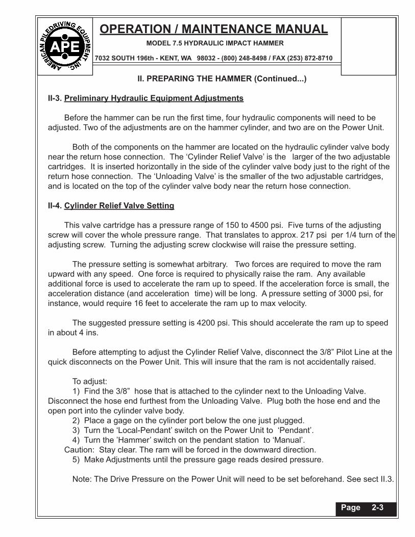
II-3. Preliminary Hydraulic Equipment Adjustments
Before the hammer can be run the first time, four hydraulic components will need to be adjusted. Two of the adjustments are on the hammer cylinder, and two are on the Power Unit.
Both of the components on the hammer are located on the hydraulic cylinder valve body near the return hose connection. The ‘Cylinder Relief Valve’ is the larger of the two adjustable cartridges. It is inserted horizontally in the side of the cylinder valve body just to the right of the return hose connection. The ‘Unloading Valve’ is the smaller of the two adjustable cartridges, and is located on the top of the cylinder valve body near the return hose connection.
II-4. Cylinder Relief Valve Setting
This valve cartridge has a pressure range of 150 to 4500 psi. Five turns of the adjusting screw will cover the whole pressure range. That translates to approx. 217 psi per 1/4 turn of the adjusting screw. Turning the adjusting screw clockwise will raise the pressure setting.
The pressure setting is somewhat arbitrary. Two forces are required to move the ram upward with any speed. One force is required to physically raise the ram. Any available additional force is used to accelerate the ram up to speed. If the acceleration force is small, the acceleration distance (and acceleration time) will be long. A pressure setting of 3000 psi, for instance, would require 16 feet to accelerate the ram up to max velocity.
The suggested pressure setting is 4200 psi. This should accelerate the ram up to speed
in about 4 ins.
Before attempting to adjust the Cylinder Relief Valve, disconnect the 3/8” Pilot Line at the quick disconnects on the Power Unit. This will insure that the ram is not accidentally raised.
To adjust: 1) Find the 3/8” hose that is attached to the cylinder next to the Unloading Valve.
Disconnect the hose end furthest from the Unloading Valve. Plug both the hose end and the open port into the cylinder valve body.
2) Place a gage on the cylinder port below the one just plugged. 3) Turn the ‘Local-Pendant’ switch on the Power Unit to ‘Pendant’. 4) Turn the ’Hammer’ switch on the pendant station to ‘Manual’.Caution: Stay clear. The ram will be forced in the downward direction. 5) Make Adjustments until the pressure gage reads desired pressure. Note: The Drive Pressure on the Power Unit will need to be set beforehand. See sect II.3.

OPERATION / MAINTENANCE MANUALMODEL 7.5 HYDRAULIC IMPACT HAMMER
7032 SOUTH 196th - KENT, WA 98032 - (800) 248-8498 / FAX (253) 872-8710
Page 2-4
II. PREPARING THE HAMMER (Continued...)
II-5. Cylinder Unloading Valve Pressure Setting
The purpose of the Unloading Valve is to lower the Drive pressure once the pressure accumulators on the hammer are charged. This feature would be useful only is the hammer is to be used in the Manual Mode for long periods of time; or if the hammer is to be run with long Dwell Times in the Auto Mode. Either of the above conditions could create a heat buildup in the oil temperature.
The down side of using the unloading feature is that, unless the engine rpm is adjusted just right, the pressure hose to the hammer will be cycling between high and low pressures, causing the hoses to jump. For normal operation, it is suggested that the hammer will be easier to control if the unloading feature is not used.
If the Unloading Valve pressure is set below the relief pressure, the unloading feature will be operational. If the Unloading Valve pressure is set above the Relief pressure, the unloading feature will not be in effect.
To adjust the Unloading Valve to be operational: 1) Reconnect the hose that was disconnected per step 1 in the previous section. Leave the pressure gage connected. 2) Turn the ‘Local-Pendant’ switch on the Power Unit to ‘Pendant’. 3) Turn the ’Hammer’ switch on the pendant station to ‘Manual’.Caution: Stay clear. The ram will be forced in the downward direction. 4) Make Adjustments until the Power Unit unloads about 200 psi below the
Relief setting. Turning the adjusting screw clockwise will raise the pressure setting. Five turns are required for the full range of the valve.
Note: Between each adjustment; 5) Turn the ’Hammer’ switch to the ’Off’ Position. 6) Turn the ’Unload’ switch on the pendant to the ’Unload’ position to unload
the accumulators. 7) Repeat steps nos 3 thru 6 . To adjust the Unloading Valve to be non operational: Following the steps above, continue to raise the Unloading Valve pressure until the Power Unit does not unload.
OPERATION / MAINTENANCE MANUALMODEL 7.5 HYDRAULIC IMPACT HAMMER
7032 SOUTH 196th - KENT, WA 98032 - (800) 248-8498 / FAX (253) 872-8710
II. PREPARING THE HAMMER (Continued...)
II-6. Power Unit Drive Valve Pressure Setting
The Drive Valve on the Power Unit should be set about 300 psi above the Cylinder Relief Valve pressure setting. This should take care of the pressure drop in the hose to the hammer.
II-7. Power Unit Clamp Valve Pressure Setting
The Clamp Valve pressure setting should be about 300 psi above the Cylinder Relief Valve pressure setting.
Page 2-5

OPERATION / MAINTENANCE MANUALMODEL 7.5 HYDRAULIC IMPACT HAMMER
7032 SOUTH 196th - KENT, WA 98032 - (800) 248-8498 / FAX (253) 872-8710
Page 3-1
III. HAMMER CONTROL (Continued...)
III-1. Hammer Control
The hammer control consists of a Control Enclosure and a Pendent Station, interconnected via a 16 conductor SO cord. The Control Enclosure should be mounted to the Power Unit just below the Power Unit Control Enclosure. The Hammer Control is connected to the Power Unit control enclosure via an Amphenol Plug.
III.a Emergency Stop Button The Emergency stop Button is located at the very top of the pendant station. Depressing this button will kill the Power Unit Engine.
III.b Governor Switch This switch is located just below the ‘Emergency Stop’ Button in the Pendent Station. Turn this switch to the left to lower the Power Unit Engine RPM. Turn the switch to the right to raise the engine rpm.
Note: If the engine rpm is increased while the hammer is operating, the stroke will increase. Be careful.
III.c Stroke Timer The Stroke Timer is the primary control, regulating the length of the ram stroke. Until the operator is really familiar with the hammer’s operational characteristics, the hammer should be started with a low stroke setting, then increased after the hammer is operating.
Note: If the engine rpm is increased while the hammer is operating, the stroke will increase. Be careful.
III..d Dwell Timers There are two dwell timers. One is in the Control Enclosure. The other is below the Stroke Timer on the Pendent Station. Effectively, they
are additive in time.
III.d.1 Timer in the Control Enclosure This timer begins timing at the end of the up stroke. It’s purpose is to allow enough time for the ram to drop before the next stroke is began. If this timer is set too high, the hammer cycle rate will be decreased. If it is set too low, the operator could begin a new stroke cycle before the ram has reached the bottom of it’s downward stroke.
The setting for a 5 ft drop, should be about .55 seconds.

OPERATION / MAINTENANCE MANUALMODEL 7.5 HYDRAULIC IMPACT HAMMER
7032 SOUTH 196th - KENT, WA 98032 - (800) 248-8498 / FAX (253) 872-8710
Page 3-2
III. HAMMER CONTROL (Continued...)
III-1. Hammer Control (continued)
III.d.2 Dwell Timer in Pendant Station This timer is located just below the Stroke Timer. It begins timing when the above timer has timed out. It’s function is to regulate dwell time between ram impact and the beginning of the next cycle.
Until the operator is really familiar with the hammer’s operational characteristics, the hammer should be started with a High Dwell setting, then decreased after the hammer is operating.
III.eHammer Switch This is the very bottom switch in the Pendent Station. Turning this switch to either the ‘Manual’ mode or the ‘Auto’ mode will energize the Drive Valve in the Power Unit.
If this switch is turned to either the ’Manual’ mode or the ’Auto mode for long periods of time without cycling the hammer, there can be a heat buildup in the hydraulic oil, especially if the Unloading Valve is not being used.
Note: The engine can not be started if this switch in not in the ‘Off’ position.
III.f Unload/Start Switch This is the switch with the Green knob, located just above the Hammer switch. It has three functions. 1) Turn this switch to the ‘Unload’ position to unload the pressure stored in
the accumulators on the hammer. This will work only if the ‘Hammer’ switch is in the ‘Off’ position.
2) When the ‘Hammer’ switch is in the ‘Manual’ mode, the ram can be manually
operated by turning this switch to the ‘Start’ position. Each time the switch is turned to the ‘Start’ position, the ram will raise. Releasing the switch will drop the ram.
If the Power Unit engine is not running, this step can be useful to check the cylinder for internal leakage. Without the engine running, and the ‘Hammer’ switch in the ‘Manual’ mode, turn and hold this switch to the ‘Start’ position. The pressurized oil in the accumulators will partially raise the ram. If the ram stays in position, everything is okay. If the ram moves down, there is internal leakage.
3) When the ‘Hammer’ switch is in the ‘Auto’ position, turning this switch to the ‘Start’ position will start the first cycle.

OPERATION / MAINTENANCE MANUALMODEL 7.5 HYDRAULIC IMPACT HAMMER
7032 SOUTH 196th - KENT, WA 98032 - (800) 248-8498 / FAX (253) 872-8710

OPERATION / MAINTENANCE MANUALMODEL 7.5 HYDRAULIC IMPACT HAMMER
7032 SOUTH 196th - KENT, WA 98032 - (800) 248-8498 / FAX (253) 872-8710
Page 3-3
II. PREPARING THE HAMMER (Continued...)
III-2. Setting up Stroke Control SystemTo use the Hammer Control, plug the control cord into the amphenolPlug on the bottom of the Power Unit Control Enclosure, turn the Remote Control Switch to “Pendant“.
There are 7 Control functions on the Control .
1) MODE SWITCH (Located on the Hammer Control Enclosure) —Select M8 for the Model 8 Hammer. —Select M12 for the Model 12 Hammer.
2) ENGINE RPM (Governor Control is Located in the Pendant) —Raising the engine RPM will shorten the cycle time and increase the stroke length. If the hammer is stroking near maximum, decrease the time on timer #1 before raising the engine RPM. 3) TIMER #1 (Located inside the Hammer Control Enclosure.) —Increasing the time on timer #1 will increase the stroke of the hammer. When first starting a hammer, begin with a low set time and slowly increase the time until the desired stroke length is achieved.
4) TIMERS #2 &3 (Located inside the Hammer Control Enclosure.) — Timer #2 and Timer #3 do exactly the same thing. They both regulate the dwell time between strokes. (Once a minimum dwell time is established, the dial on timer #3 should be locked with a drop or two of epoxy glue.) Timer #2 can then be used to increase the dwell above the minimum set on timer #3. When first starting a hammer, begin with a high dwell time, and slowly decrease the time until the desired dwell time is achieved.
5) HAMMER CONTROL (Located in the Pendant.) — HAND When the Hammer Control selector is in the “Hand” position, the hammer will cycle once each time the “Cycle” button is pressed. —AUTO When the Hammer Control selector is in the “Auto” position, the hammer will run continuously. —OFF This Switch must be in the “off” position before the engine can be started.
6) CYCLE BUTTON (Located in the Pendant) — See “Hand” selection above.
7) EMERGENCY STOP (Located in the Pendant) —Pressing this button will kill the engine.

OPERATION / MAINTENANCE MANUALMODEL 7.5 HYDRAULIC IMPACT HAMMER
7032 SOUTH 196th - KENT, WA 98032 - (800) 248-8498 / FAX (253) 872-8710
Page 4-1 Figure 4-A 7.5 HIH Final Assembly

OPERATION / MAINTENANCE MANUALMODEL 7.5 HYDRAULIC IMPACT HAMMER
7032 SOUTH 196th - KENT, WA 98032 - (800) 248-8498 / FAX (253) 872-8710
Page 4-2Figure 4-B Cylinder Assembly

OPERATION / MAINTENANCE MANUALMODEL 7.5 HYDRAULIC IMPACT HAMMER
7032 SOUTH 196th - KENT, WA 98032 - (800) 248-8498 / FAX (253) 872-8710
Page 4-3
Item Qty Description Figure #
1 1 Top Plate Assembly 3-A1a 2 Accumulator Holddown Clamps 3-A1b 4 B7 Studs 1/2" x 7" Lg 3-A1c 4 1/2" Nylock Nuts 3-A1d 2 Top Ram Bumper Cushions 3-A1e 4 3/8" x 3" Lg Carriage Bolts 3-A1f 4 3/8" Torque Washer 3-A1g 4 3/8" Nylock Nut 3-A1h 3 Socket Head Bolts 3/4" x 4 1/2" Lg 3-A1i 3 3/4" Nylock Nuts 3-A2 4 Tie Rods 3-A2a 8 3"-4 Hex Nuts 3-A2b 8 Nut Lock Bar (welded in place) 3-A3 2 Lead Guide Channels 3-A3a 16 Hex Bolts 7/8" x 4 1/2" Lg (Gr 8) 3-A3b 16 7/8" Stover Nuts 3-A4 2 Floating Sheave Guide Channels 3-A4a 6 Hex Bolts 7/8" x 5" Lg 3-A4b 6 7/8" Stover Nuts 3-A4c 8 Socket Head Bolts 5/8" x 3" Lg 3-A4d 8 5/8" Stover Nuts 3-A5 1 Floating Sheave Assembly 3-A5a 1 McKissick Sheave #4200572 (14" dia x 2" bore x 3/4" wire) 3-A5b 1 2" Axle 3-A5c 1 1/4" Alemite Grease Fitting 3-A5d 1 Keeper Bar 3-A5e 2 Bolt 1/2" x 1 1/2" Lg (Gr 8) 3-A5f 2 1/2" Heavy Lock Washer 3-A5g 1 Replacement Brg (McGill #MR36 Roller Bearing) 6 1 Bottom Plate Assembly and Striker Plate Cage 3-A6a 2 Bottom Ram Bumper Cushions 3-A6b 4 3/8" x 3" Lg Carriage Bolts 3-A6c 4 3/8" Torque Washer 3-A6d 4 3/8" Nylock Nut 3-A6e 1 #MIT 248 Dock Bumper 3-A6f 2 Bolt 1/2" x 4" Lg (Gr 5) 3-A6g 2 1/2" Nylock Nuts 3-A7 1 Striker Plate 3-A7a 1 Striker Plate Cushion 3-A7b 1 Rebound Ring 3-A
OPERATION / MAINTENANCE MANUALMODEL 7.5 HYDRAULIC IMPACT HAMMER
7032 SOUTH 196th - KENT, WA 98032 - (800) 248-8498 / FAX (253) 872-8710
Page 4-4
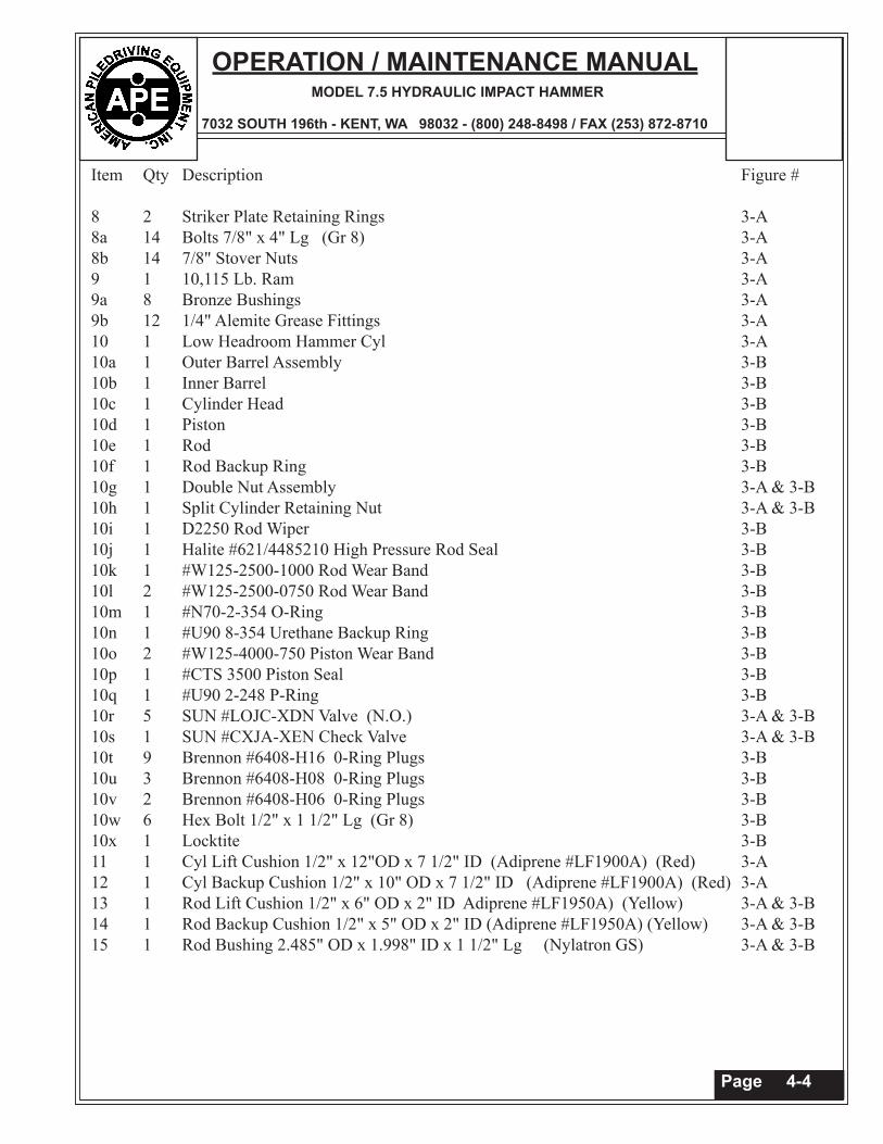
Item Qty Description Figure #
8 2 Striker Plate Retaining Rings 3-A8a 14 Bolts 7/8" x 4" Lg (Gr 8) 3-A8b 14 7/8" Stover Nuts 3-A9 1 10,115 Lb. Ram 3-A9a 8 Bronze Bushings 3-A9b 12 1/4" Alemite Grease Fittings 3-A10 1 Low Headroom Hammer Cyl 3-A10a 1 Outer Barrel Assembly 3-B10b 1 Inner Barrel 3-B10c 1 Cylinder Head 3-B10d 1 Piston 3-B10e 1 Rod 3-B10f 1 Rod Backup Ring 3-B10g 1 Double Nut Assembly 3-A & 3-B10h 1 Split Cylinder Retaining Nut 3-A & 3-B10i 1 D2250 Rod Wiper 3-B10j 1 Halite #621/4485210 High Pressure Rod Seal 3-B10k 1 #W125-2500-1000 Rod Wear Band 3-B10l 2 #W125-2500-0750 Rod Wear Band 3-B10m 1 #N70-2-354 O-Ring 3-B10n 1 #U90 8-354 Urethane Backup Ring 3-B10o 2 #W125-4000-750 Piston Wear Band 3-B10p 1 #CTS 3500 Piston Seal 3-B10q 1 #U90 2-248 P-Ring 3-B10r 5 SUN #LOJC-XDN Valve (N.O.) 3-A & 3-B10s 1 SUN #CXJA-XEN Check Valve 3-A & 3-B10t 9 Brennon #6408-H16 0-Ring Plugs 3-B10u 3 Brennon #6408-H08 0-Ring Plugs 3-B10v 2 Brennon #6408-H06 0-Ring Plugs 3-B10w 6 Hex Bolt 1/2" x 1 1/2" Lg (Gr 8) 3-B10x 1 Locktite 3-B11 1 Cyl Lift Cushion 1/2" x 12"OD x 7 1/2" ID (Adiprene #LF1900A) (Red) 3-A12 1 Cyl Backup Cushion 1/2" x 10" OD x 7 1/2" ID (Adiprene #LF1900A) (Red) 3-A13 1 Rod Lift Cushion 1/2" x 6" OD x 2" ID Adiprene #LF1950A) (Yellow) 3-A & 3-B14 1 Rod Backup Cushion 1/2" x 5" OD x 2" ID (Adiprene #LF1950A) (Yellow) 3-A & 3-B15 1 Rod Bushing 2.485" OD x 1.998" ID x 1 1/2" Lg (Nylatron GS) 3-A & 3-B

OPERATION / MAINTENANCE MANUALMODEL 7.5 HYDRAULIC IMPACT HAMMER
7032 SOUTH 196th - KENT, WA 98032 - (800) 248-8498 / FAX (253) 872-8710
Page 4-5
Item Qty Description Figure #
1 1 Vynckier #VJ1008HWPL-1 Enclosure 3-C2 1 Vynckier #MP1008S Back Panel 3-C3 1 Iboco Wire Duct (1” x 1 1/2” grey) x 20” Lg 3-C4 1 DIN Rail 3-C5 2 Idec #BNL6 Mounting Clip 3-C6 3 Idec #BNF10DW Fuse Block 3-C
Figure 4-C Control Assembly

OPERATION / MAINTENANCE MANUALMODEL 7.5 HYDRAULIC IMPACT HAMMER
7032 SOUTH 196th - KENT, WA 98032 - (800) 248-8498 / FAX (253) 872-8710
Page 4-6
Item Qty Description Figure #
7 1 Idec #BNE20 End Plate for Fuseblock 3-C8 2 MDL-5 Buss Fuses 3-C 9 1 MDL-8 Buss Fuses 3-C10 2 Idec #SH1B-05 Socket 3-C11 2 Idec #RH1B-DC24V 3-C12 1 Idec # SR3P-05 Socket 3-C13 1 Idec #RR2KP DC24V 3-C14 1 Idec #SR2P-06 Socket 3-C15 1 Crouzett #88.867.135 Off Delay Timer 3-C16 1 Blue Plastic Nameplate 1/2” x 2” (BLOW COUNT) 3-C17 1 Syrelec Counter No 87-610-040 3-C18 1 Blue Plastic Nameplate 1/2” x 1” (RESET) 3-C19 1 Idec #AB6M-BK1-R Red Button 3-C20 1 Idec #AB6M-M100 Switch Body 3-C21 1 #16AGW 14 Conductor SO Cord x 60 Ft Lg 3-C22 1 #RB-322S Reducing Bushing (1” x 3/4”) 3-C23 3 O-Z #SR-757 CGB Fitting 3-C24 2 3/4” Myers Hubs 3-C25 1 Amphenol #MS3106A-28-18P Plug 3-C26 1 Amphenol #MS3420-16 3-C27 1 Amphenol # MS3057-16A 3-C28 1 Sq D# 9001-SKYP6 6 Hole Pendant Station 3-C29 1 CH #10250T122 Pushbutton Opp w/ Mushroom Hd 3-C30 1 CH #10250T53 Contact Block (1 NO) 3-C31 1 Sq D# 9001-SKN200 Blank Name Plate 3-C32 1 Engraving (“Emerg Stop” “Lower-GOV- Raise”) 3-C33 1 CH #10250 T1343 , 3 Pos Selector (spring to ctr) 3-C34 1 CH #10250 T2 Contact Block (2 NO) 3-C35 1 CH #E22ARK Adaptor 3-C36 1 Crouzet #88.901.102 Timers 24vdc (.01 to 1 sec) 3-C37 1 Sq D# 9001-SKN200 Blank Name Plate 3-C38 1 Engraving (“Stroke” “Dwell”) 3-C39 1 CH #E22ARK Adaptor 3-C40 1 Crouzet #88.901.112 Timers 24vdc (.15 to 3 sec) 3-C41 1 CH #10250 T103 Pushbutton Operator (green) 3-C42 1 CH #10250 T53 Contact Block (1 NO) 3-C43 1 Sq D# 9001-SKN200 Blank Name Plate 3-C44 1 Engraving (“Cycle” “Hammer”-Hand-Off-Auto”) 3-C45 1 CH#10250 T1323 , 3 pos selector (maint) 3-C46 1 CH#10250 T44 Cont Block (2 NC, 2 NO) 3-C47 1 CH#10250 T2 Cont Block (2 NO) 3-C

OPERATION / MAINTENANCE MANUALMODEL 7.5 HYDRAULIC IMPACT HAMMER
7032 SOUTH 196th - KENT, WA 98032 - (800) 248-8498 / FAX (253) 872-8710

OPERATION / MAINTENANCE MANUALMODEL 7.5 HYDRAULIC IMPACT HAMMER
7032 SOUTH 196th - KENT, WA 98032 - (800) 248-8498 / FAX (253) 872-8710
Page 5-1
V. HYDRAULIC CIRCUIT
Figure 5-A. Hydraulic Circuit

OPERATION / MAINTENANCE MANUALMODEL 7.5 HYDRAULIC IMPACT HAMMER
7032 SOUTH 196th - KENT, WA 98032 - (800) 248-8498 / FAX (253) 872-8710
VI. ELECTRIC CIRCUIT
Figure 6-A. Electric CircuitPage 6-1

OPERATION / MAINTENANCE MANUALMODEL 7.5 HYDRAULIC IMPACT HAMMER
7032 SOUTH 196th - KENT, WA 98032 - (800) 248-8498 / FAX (253) 872-8710
VII. APPLICATION
Figure 7-A. Typical Low Headroom Application
Figure 7-B. Typical Forklift Application Page 7-1