operation and maintenance manual - tom logisch · operation and maintenance manual 1. introduction...
TRANSCRIPT

1
OPERATION AND MAINTENANCE MANUAL
1. Introduction
1.1. General
1.2. Technical data
1.3. System description
2. Installation
2.1. General criteria and material required
2.2. Components mounting
2.3. Water intake
2.4. Hydraulic connections
2.5. Electric connections
3. Operating procedures
3.1. First start-up procedure
3.2. Normal operating procedure
4. Maintenance
4.1. Shutdown procedure
4.2. Maintenance and recurrent inspections
4.3. Troubleshooting
5. Safety cautions
6. Most frequent operations summary table.
7. Warranty

2
Rev. 2014
1. Introduction
1.1 General
Thank you for choosing a Schenker Watermaker which we know will give you years of ser-
vice, making life onboard more enjoyable.
To ensure the maximum efficiency of your Schenker Watermaker and its trouble free working,
Please read this manual and to keep it onboard for reference.
The Smart 30 watermaker uses Schenker’s patented ENERGY RECOVERY SYSTEM which
amplifies the pressure of common low pressure pumps, and recoups all the hydraulic energy back
from the membrane. This saves on the use of power, allowing the Smart 30 to be run directly
from the vessels batteries.
The ENERGY RECOVERY SYSTEM operating components are reduced to a minimum, thanks
to two internationally patented solutions that eliminate the need for pilot valves.
The lack of high-pressure pumps ensure the system is silent and vibration free. It also means that
no adjustments are required when the system is started up.
3
1. Introduction
1.2 Technical data
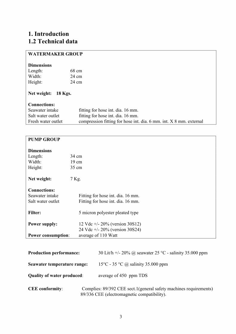
WATERMAKER GROUP
Dimensions
Length: 68 cm
Width: 24 cm
Height: 24 cm
Net weight: 18 Kgs.
Connections:
Seawater intake fitting for hose int. dia. 16 mm.
Salt water outlet fitting for hose int. dia. 16 mm.
Fresh water outlet compression fitting for hose int. dia. 6 mm. int. X 8 mm. external
PUMP GROUP
Dimensions
Length: 34 cm
Width: 19 cm
Height: 35 cm
Net weight: 7 Kg.
Connections:
Seawater intake Fitting for hose int. dia. 16 mm.
Salt water outlet Fitting for hose int. dia. 16 mm.
Filter: 5 micron polyester pleated type
Power supply: 12 Vdc +/- 20% (version 30S12)
24 Vdc +/- 20% (version 30S24)
Power consumption: average of 110 Watt
Production performance: 30 Lit/h +/- 20% @ seawater 25 °C - salinity 35.000 ppm
Seawater temperature range: 15°C - 35 °C @ salinity 35.000 ppm
Quality of water produced: average of 450 ppm TDS
CEE conformity: Complies: 89/392 CEE sect.1(general safety machines requirements)
89/336 CEE (electromagnetic compatibility).

4
1. Introduction
1.3 System description
The SMART system comprises of two separate units:
� PUMP AND FILTER GROUP.
This unit have the duty of picking the sea water up and send it to the watermaker unit at a certain
pressure (about 7,5 – 8 Bar). The pump is equipped with a pres-
sure switch for high-pressure shutdowns, calibrated at about 9
Bar.
Pressure switch detail
The filter is based on a 5 micron filtering cartridge. It filters the impurities that may cause dam-
age to the watermaker. A red push-button air purge is sited on top of the filter unit to allow the
removal of air at the beginning of start-up operations.
Close to the pump is the pressure accumulator.(similar to that used on your domestic pressure
water system) This equalizes the water pressure during the watermaker cycles. The accumulator
is pre-charged to a pressure of 2.8 Bar.
� WATERMAKER GROUP.
The watermaker group comprises of the following components:
The Reverse osmosis membrane, inside the silver high-pressure vessel is used to separate the
intake high-pressure seawater into two flows: one for the salt-water waste and one for fresh water
production.
Reset valve
Depressurization
valve
Positioner knob

5
Energy Recovery System. Amplifies the pressure supplied by the pump and recovers the hy-
draulic energy back from the membranes. The ERS device makes periodic cycling by a hydrauli-
cally controlled automatic valve. The cycles are noticeable through a” beat” issued periodically
by the watermaker unit. The unit contains two cylinders, and a central body housing the hydraulic
valves.
Manometer. It is located on the front of the ERS, and it measures the pump running pressure.
Depressurization valve. Is used during the air bleeding operations, mainly at the first plant
start-up. This is a blue lever located on the rear of the watermaker. Its function is to depressurize
the system and allow air bleeding. The valve remains closed during normal working conditions
and is opened only during the air bleeding operations. The lever need only be opened halfway
(45°) during air bleeding operations.
Positioner: A stainless steel threaded arm, with a black knob, located on the right side of the
unit. Its function is to reset the unit in start up failure.
Reset valve. Is installed on the left of the ERS and it is a small little blue plastic lever. The valve
must be closed during normal functioning (lever perpendicular to the valve). This valve allows
resetting in case of a system failure It must be opened before using the valve positioner.
Accessories:
Active carbon filter with electrovalve: It removes the chlorine from the pressurized flushing
fresh water (the chlorine could damage the reverse osmosis membranes).
It is fitted with an electrovalve, controlled from the selector “flushing” of the remote panel.
Srainer: The strainer (installed on the suction of the pump) protects the pump from gross sedi-
ments that could damage the pump head.
Non return valve. It avoids the emptying of the suction pipe of the pump, and allows to perform
the rinsing of the unit. It must be installed vertically and as close as possible to the water inlet.
2. Installation
2.1 General criteria A planned installation will make both fitting and operation of your Smart 30 watermaker easier.
Below need to be taken into account with your installation:
� An appropriate seawater intake with necessary fittings.
� Positioning of Pump & Watermaker units.
� Positioning of pump operation automatic circuit breakers.
� Pipework and cables laying.
A good installation needs to be easy to use, easy to access for maintenance and filter changes. All
Watermaker components have been designed to achieve all of this. Draw a schematic electric and
hydraulic connection diagram when installation solution is complete and keep it with this manual
for reference.

6
2. Installation
2.2 Components mounting
� Pump group.
The pump is partially self-priming. Anyway it is strictly recommended to install the pump below
the watermaker, and as low as possible respect the sea level, and as close as possible respect
the sea water intake.
The pump needs to be installed inside to adequately ventilated room to allow the cooling of the
pump and avoiding condensation.
Do not install the pump unit close to inflammable liquids, as the pump surfaces can become
heated.
Avoid locating the pump where a loss of water can cause damage or jeopardize its safety.
Allow sufficient space for access to the casing containing the filter cartridge.
The pump must be installed horizontally on a suitable base, strong enough to support its weight
when the filter housing is full of water.
It may be necessary to create a suitable wooden or fiberglass structure for the unit, if an existing
one not available. The base of the pump is equipped with vibration-damping devices, but avoid
installing it on a surface susceptible to vibration.
The pump unit can be a little noisy in operation. Possible are: sink closets, under berth lockers,
wardrobe bases (creating a false floor above it.) The unit can be fixed on the supporting structure
using the screws supplied with the equipment or the bolts with nuts and washers. � Watermaker unit
The watermaker unit is totally hydraulic and needs no electricity. It can be installed in areas in-
side exposed to humidity, or to the presence of inflammable vapors. It can be installed at any
height inside the vessel. Avoid installing the system wherever a leak will cause damage to the
boat or jeopardize its safety.
The hydraulic intake and outlet connections are positioned in the standard version, on the left
hand side of the unit. It is necessary to leave a minimum distance of 20 cm. to allow pipe laying.
The pump must be installed horizontally on a suitable base, strong enough to support its weight.
(20kg)
The base of the pump is equipped with vibration-damping devices, but avoid installing it on a
surface susceptible to vibration.
Possible locations of the watermaker group are: engine compartment, under berth lockers, cock-
pit lockers. Install the unit where access to valves and instrumentation is visible.
The unit can be fixed on the supporting structure using the screws supplied with the equipment
or the bolts with nuts and washers.
2. Installation
2.3 Water intakes
The necessary hydraulic intakes are:
• Seawater intake.
It is ideal a specific sea water intake, size ¾” min. in a central position, well under the water sur-
face even when the vessel is well heeled over.
The skin fitting is recommended. It must be oriented to the bow of the boat.
As alternative it is possible Tee into an water inlet as long as the following conditions are met:

7
- 3/4” minimum size,
- No air can be introduced into the system from other use ie: salt water tap in galley
-Must always be under the water surface even when the vessel is well heeled over.
Allow a minimum ½” on-off ball valve on the water intake. The hose connections, especially if
under the seawater level, must be secured with double hose clamps.
It is not advisable to Tee into the engine cooling water intake as it may impair the cooling of the
engine. An easily inspected mesh type filter will be required close to the water intake. The filter
has to be of 50 microns. It is possible to use filters from existing outlets.
• Fresh water intake for flushing.
Tee in downstream of the vessel's fresh water pressure system (Domestic water from tank) .
The following conditions must be respected :
The flow of the existing fresh water pump must be min 5 lit/min.
Flushing must always be carried out with the pressure water system ON, and the grey valve on
the AC filter opened.
• Salt-water waste. (After passing through the watermaker)
The salt-water drain shall be ½” minimum size and it has to be preferably above the seawater
level.
It is possible to use offtakes from existing apparatuses, provided that it is not the engine cooling
water drain or apparatuses that drain out water with elevated pressure.
8
2. Installation
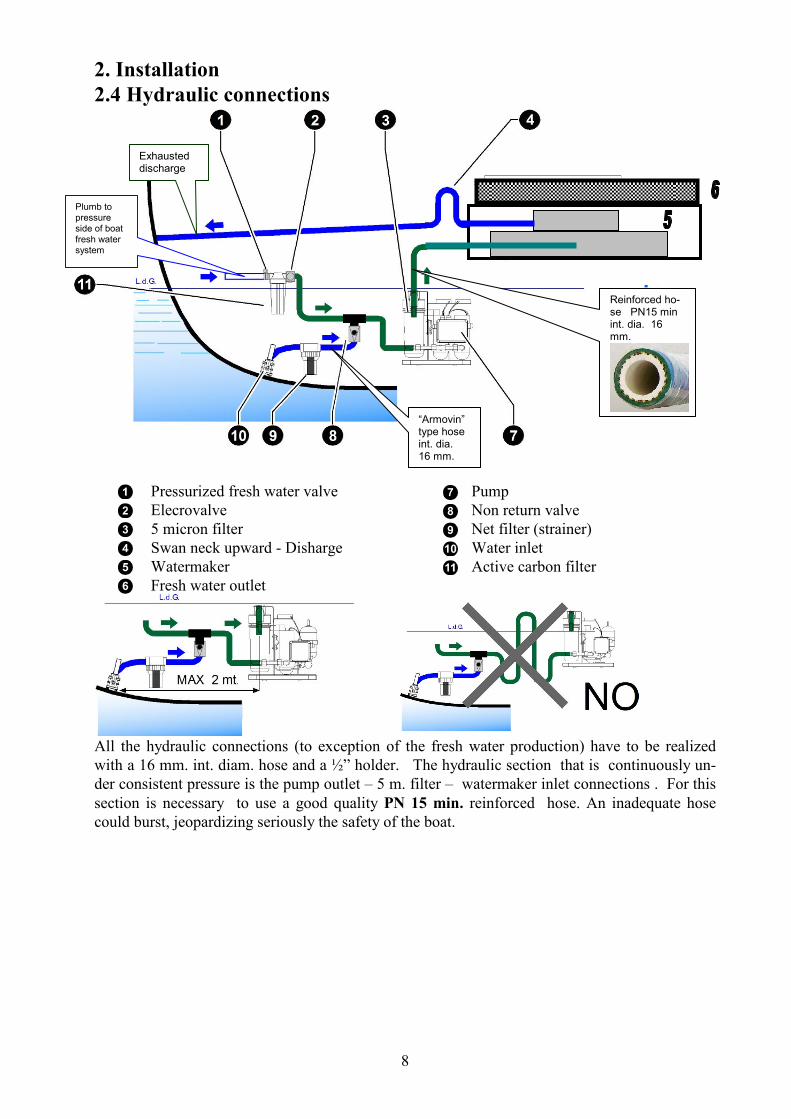
2.4 Hydraulic connections
Pressurized fresh water valve Pump
Elecrovalve Non return valve
5 micron filter Net filter (strainer)
Swan neck upward - Disharge Water inlet
Watermaker Active carbon filter
Fresh water outlet
All the hydraulic connections (to exception of the fresh water production) have to be realized
with a 16 mm. int. diam. hose and a ½” holder. The hydraulic section that is continuously un-
der consistent pressure is the pump outlet – 5 m. filter – watermaker inlet connections . For this
section is necessary to use a good quality PN 15 min. reinforced hose. An inadequate hose
could burst, jeopardizing seriously the safety of the boat.
“Armovin” type hose int. dia. 16 mm.
Reinforced ho-se PN15 min int. dia. 16 mm.
Exhausted discharge
Plumb to pressure side of boat fresh water system
9
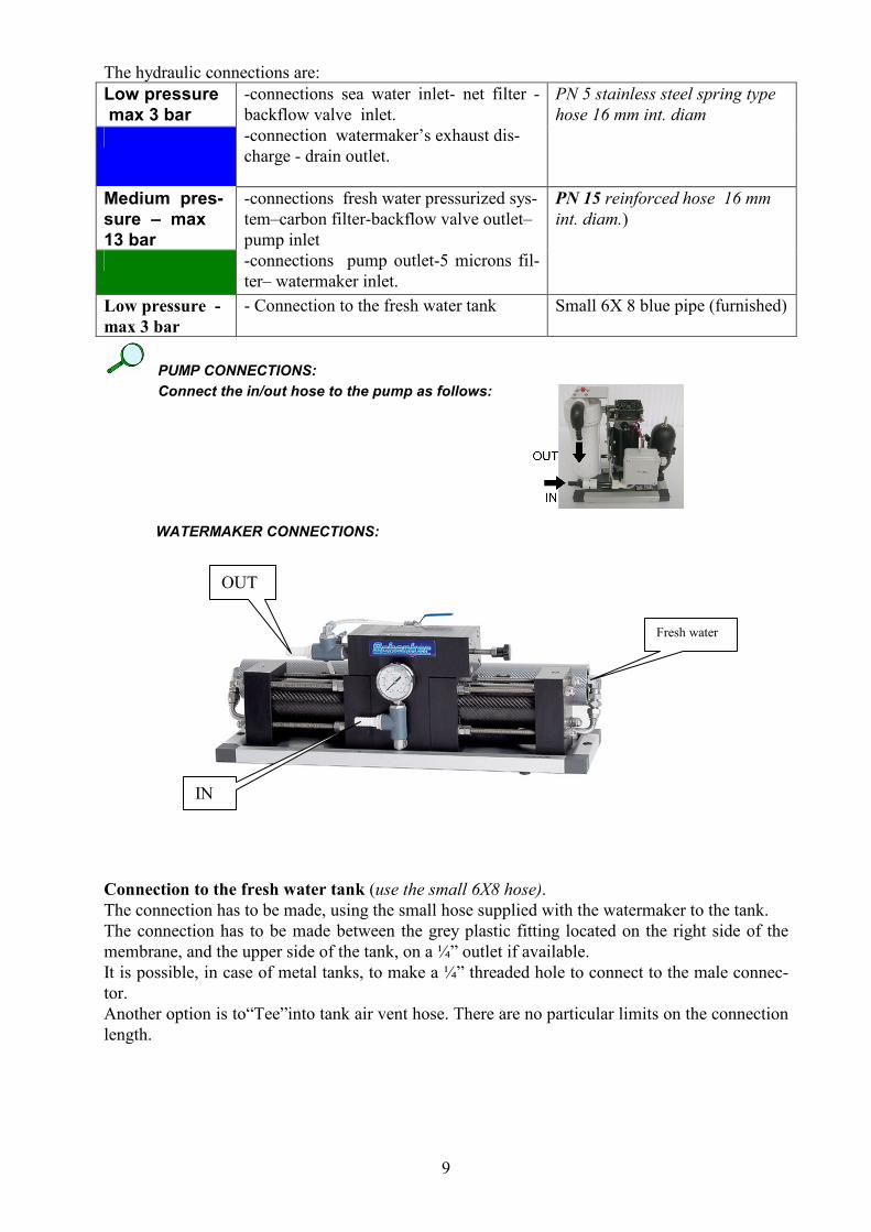
The hydraulic connections are:
Low pressure
max 3 bar
-connections sea water inlet- net filter -
backflow valve inlet.
-connection watermaker’s exhaust dis-
charge - drain outlet.
PN 5 stainless steel spring type
hose 16 mm int. diam
Medium pres-
sure – max
13 bar
-connections fresh water pressurized sys-
tem–carbon filter-backflow valve outlet–
pump inlet
-connections pump outlet-5 microns fil-
ter– watermaker inlet.
PN 15 reinforced hose 16 mm
int. diam.)
Low pressure -
max 3 bar
- Connection to the fresh water tank
Small 6X 8 blue pipe (furnished)
PUMP CONNECTIONS:
Connect the in/out hose to the pump as follows:
WATERMAKER CONNECTIONS:
Connection to the fresh water tank (use the small 6X8 hose).
The connection has to be made, using the small hose supplied with the watermaker to the tank.
The connection has to be made between the grey plastic fitting located on the right side of the
membrane, and the upper side of the tank, on a ¼” outlet if available.
It is possible, in case of metal tanks, to make a ¼” threaded hole to connect to the male connec-
tor.
Another option is to“Tee”into tank air vent hose. There are no particular limits on the connection
length.
OUT
IN
Fresh water
10
2.Installation
2.5 Electric connections
� Remote control panel mounting
The remote control panel has the following dimensions:
width 100 mm. height 75 mm.
It can be flush mounted on any surface, providing the area behind is free of moisture and conden-
sation and there is enough depth to house the rear part of the panel (approx. 70 mm.).
The cut on the mounting surface will have the following dimensions:
width 80 mm. height 50 mm.
� Wiring
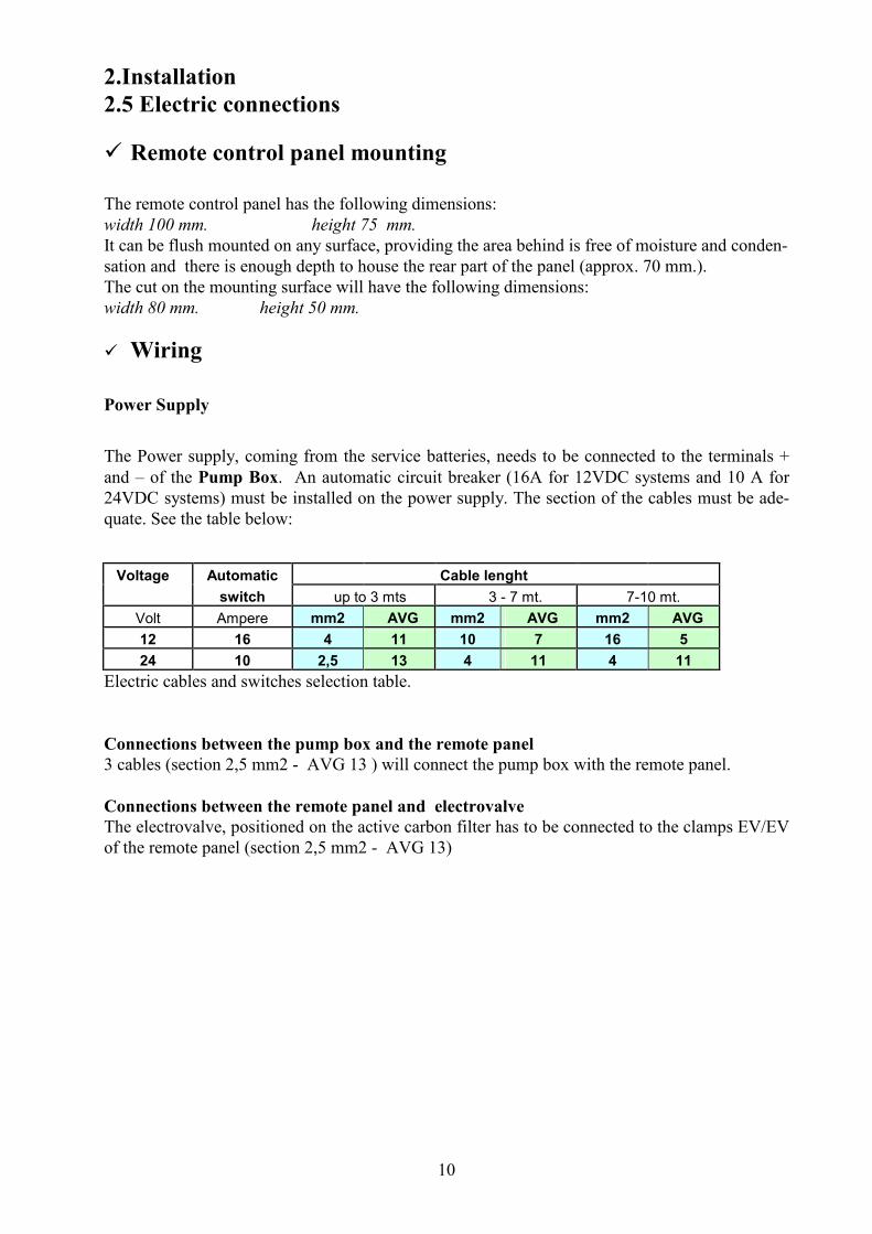
Power Supply
The Power supply, coming from the service batteries, needs to be connected to the terminals +
and – of the Pump Box. An automatic circuit breaker (16A for 12VDC systems and 10 A for
24VDC systems) must be installed on the power supply. The section of the cables must be ade-
quate. See the table below:
Voltage Automatic Cable lenght
switch up to 3 mts 3 - 7 mt. 7-10 mt.
Volt Ampere mm2 AVG mm2 AVG mm2 AVG
12 16 4 11 10 7 16 5
24 10 2,5 13 4 11 4 11
Electric cables and switches selection table.
Connections between the pump box and the remote panel
3 cables (section 2,5 mm2 - AVG 13 ) will connect the pump box with the remote panel.
Connections between the remote panel and electrovalve
The electrovalve, positioned on the active carbon filter has to be connected to the clamps EV/EV
of the remote panel (section 2,5 mm2 - AVG 13)
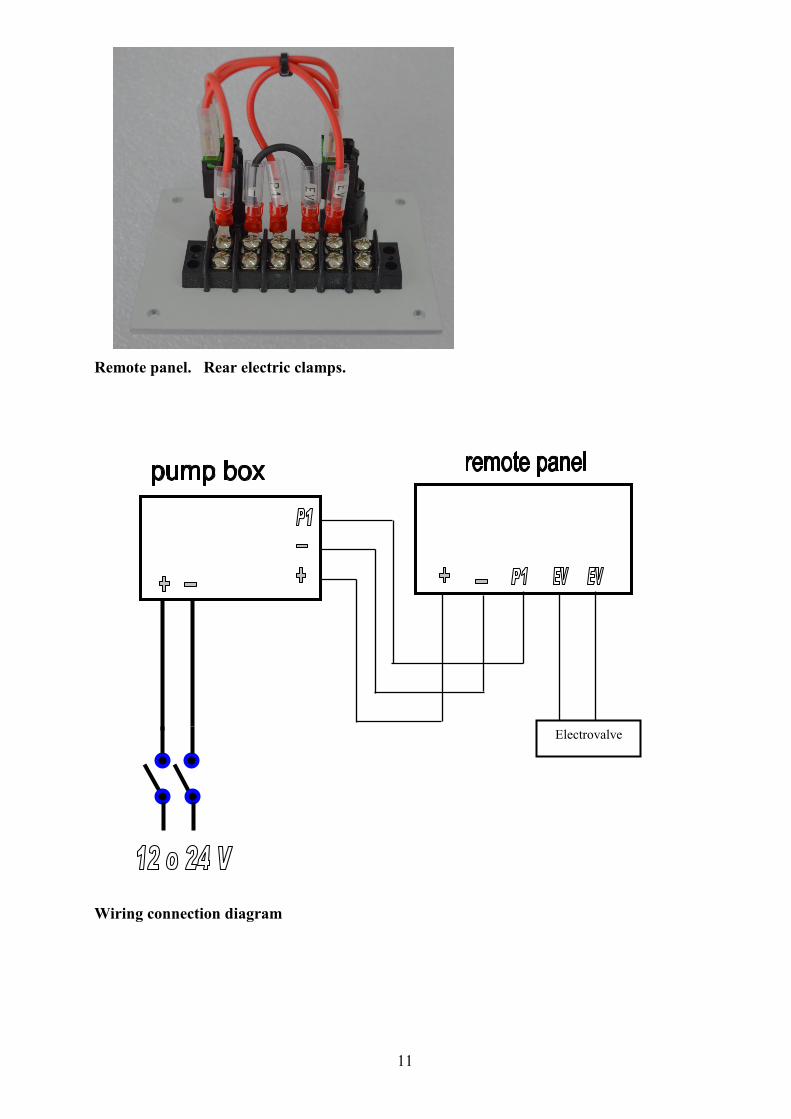
11
Remote panel. Rear electric clamps.
Wiring connection diagram
Electrovalve
12
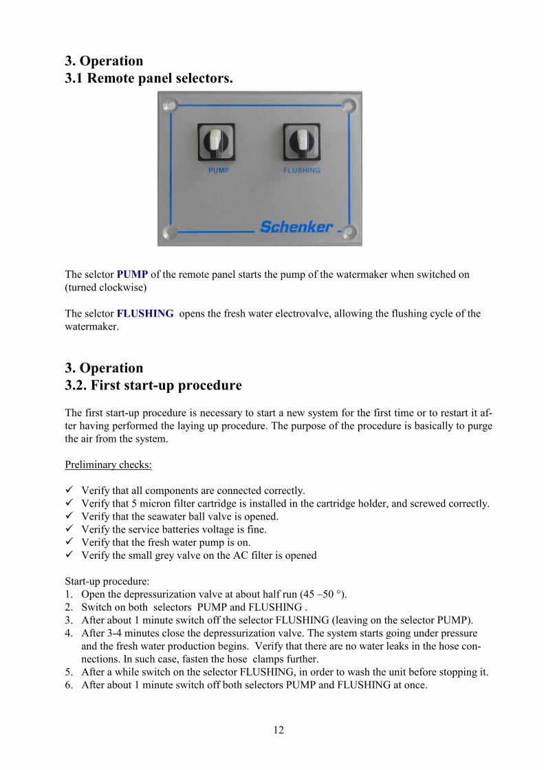
3. Operation
3.1 Remote panel selectors.
The selctor PUMP of the remote panel starts the pump of the watermaker when switched on
(turned clockwise)
The selctor FLUSHING opens the fresh water electrovalve, allowing the flushing cycle of the
watermaker.
3. Operation
3.2. First start-up procedure
The first start-up procedure is necessary to start a new system for the first time or to restart it af-
ter having performed the laying up procedure. The purpose of the procedure is basically to purge
the air from the system.
Preliminary checks:
� Verify that all components are connected correctly.
� Verify that 5 micron filter cartridge is installed in the cartridge holder, and screwed correctly.
� Verify that the seawater ball valve is opened.
� Verify the service batteries voltage is fine.
� Verify that the fresh water pump is on.
� Verify the small grey valve on the AC filter is opened
Start-up procedure:
1. Open the depressurization valve at about half run (45 –50 °).
2. Switch on both selectors PUMP and FLUSHING .
3. After about 1 minute switch off the selector FLUSHING (leaving on the selector PUMP).
4. After 3-4 minutes close the depressurization valve. The system starts going under pressure
and the fresh water production begins. Verify that there are no water leaks in the hose con-
nections. In such case, fasten the hose clamps further.
5. After a while switch on the selector FLUSHING, in order to wash the unit before stopping it.
6. After about 1 minute switch off both selectors PUMP and FLUSHING at once.
13
3. Operation
3.3. Normal operations
Fresh water production
Preliminary checks:
� Depressurization and reset valve closed
Operations:
1. Switch on the PUMP and verify the watermakert is working normally (pressure be-
tween 7 and 8 bar).
2. After produced the needed amount of fresh water, switch off the selector PUMP
Fresh water production with final flushing (recommended procedure)
Preliminary checks:
� Depressurization and reset valve closed
� Small grey valve on the AC filter is opened
Operations:
3. Switch on the PUMP and verify the watermakert is working normally (pressure be-
tween 7 and 8 bar).
4. After produced the needed amount of fresh water, switch on the selector FLUSHING,
in order to flush the unit before stopping it.
5. After about 1 minute switch off both selectors PUMP and FLUSHING at once.

14
ATTENTION If the watermaker is stopped just on the beat (on the pressure peak), or if some air is in the sys-
tem, the automatic hydraulic valve may stop in a central position. This means that pressure on
both sides of the valve are the same and the unit is effectively stalled and has to be manually re-
started.
The symptoms of this are when the pumps are turned on, the manometer reaches an elevated
pressure (approx. 9 Bar) and the pumps shutdown automatically by the pressure switches inter-
vention. The pumps then have the tendency to try to restart when the pressure decreases, and then
to jam again, resulting in a typical start-stop noiseThis phenomenon, besides being very rare,
does no harm to the system, but it is necessary to reset the valve with the following simple pro-
cedure:
RESET PROCEDURE
1. Turn pump off.
2. Open the reset valve (lever in horizontal position).
3. Screw the positioner knob clockwise until it can be moved no further.
10 turns at least are necessary.
4. Unscrew the positioner knob up to the original position, until when it is blocked
back.
5. Close the reset valve (lever in vertical position).
6. Restart the system
15
Maintenance
4.1 Shutdown procedure
It is necessary to perform the shutdown procedure before effecting standstills longer than 3
months, for instance before laying up for winter.
The purpose of the shutdown is to clean the unit of possible deposits of limestone, and to inhibit
the growth of microorganisms that may reduce the reverse osmosis membrane's efficiency.
The following equipment is necessary in order to perform the shutdown operation:
� 1 ea. recipient 20 liters minimum capacity (a bucket of such capacity could also be suitable).
� Two 16 mm. linen hoses of a length that allow them to be fed into the same container
� A prepared shutdown solution SCHENKER CLEANING 1.
� Tools for de-assembling hoses (screwdrivers, pliers, etc.)
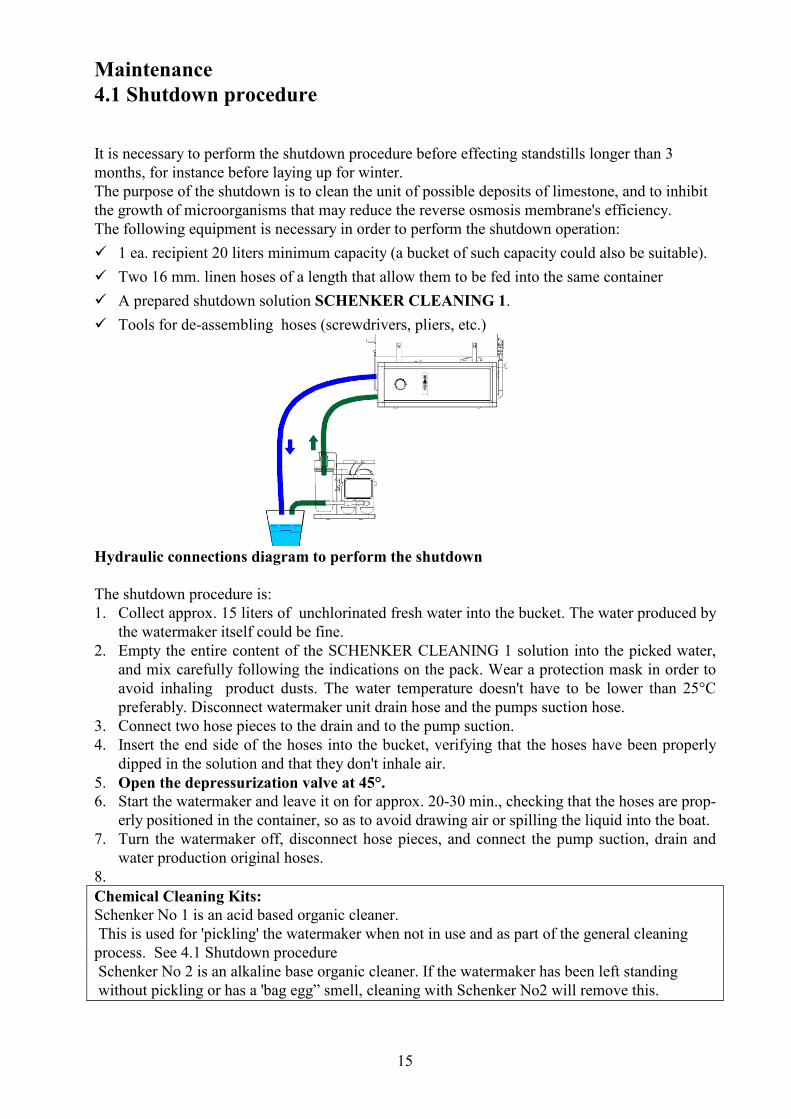
Hydraulic connections diagram to perform the shutdown
The shutdown procedure is:
1. Collect approx. 15 liters of unchlorinated fresh water into the bucket. The water produced by
the watermaker itself could be fine.
2. Empty the entire content of the SCHENKER CLEANING 1 solution into the picked water,
and mix carefully following the indications on the pack. Wear a protection mask in order to
avoid inhaling product dusts. The water temperature doesn't have to be lower than 25°C
preferably. Disconnect watermaker unit drain hose and the pumps suction hose.
3. Connect two hose pieces to the drain and to the pump suction.
4. Insert the end side of the hoses into the bucket, verifying that the hoses have been properly
dipped in the solution and that they don't inhale air.
5. Open the depressurization valve at 45°.
6. Start the watermaker and leave it on for approx. 20-30 min., checking that the hoses are prop-
erly positioned in the container, so as to avoid drawing air or spilling the liquid into the boat.
7. Turn the watermaker off, disconnect hose pieces, and connect the pump suction, drain and
water production original hoses.
8.
Chemical Cleaning Kits:
Schenker No 1 is an acid based organic cleaner.
This is used for 'pickling' the watermaker when not in use and as part of the general cleaning
process. See 4.1 Shutdown procedure
Schenker No 2 is an alkaline base organic cleaner. If the watermaker has been left standing
without pickling or has a 'bag egg” smell, cleaning with Schenker No2 will remove this.

16
4. Maintenance
4.2 Verifications and periodic maintenance
The following periodic procedures are to be followed to maintain trouble free operation:
OPERATION EVERY PROCEDURE
Strainer check and cleaning
Every 5 days
Check and clean
5 micron cartridge replacement
Every 15-20 days in average conditions (4 hours/day usage). Anyway replace it when the message CHANGE PUMP FILTERS
appears.
Unscrew anticlockwise the filter holder.
Active carbon filter replacement
Every 6 months
Purge periodically the air from the sys-tem, opening at 45° for a couple of min-utes the depressuri-zation valve
Every 15 days
Check the pressure on the manometer located on
the front panel.
The working pressure depends on many factors
such as water temperature, salinity level of sea-
water, battery voltage, cleanliness of membranes
and type of installation.
The pressure, under mid range working condi-
tions is approx. 7,5-8,5 BAR. There is a small
pressure loss , in the range of 0,2 Bars, during
the cycle.

17
4. MAINTENANCE
4.3 TROUBLESHOOTING
PROBLEM PROBABLE CAUSE SOLUTION
Pumps do not start Pump pressure switch broken Restore
Pump starts but stops at
high pressure
System blocked
Dirty filter
Dirty membranes
Trouble in the cycling system
Perform Reset
Replace cartridge
Perform cleaning cycle
Contact a Schenker service
point
While normal functioning
the pump periodically
start/stop
Pump pressure switch is not cali-
brated
Dirty filter or membranes
Calibrate pressure switch
Clean or replace
High pressure heads dur-
ing commutation
(> 0,2 Bar)
Accumulator pressure low
Inflate at a pressure of 2,8
Bar
Low production / normal
or low pressure
Low battery
Air in the system
Check battery charge
Perform bleeding
Low production / high
pressure (> 8,5 Bar)
Cold sea water
Dirty membranes
Normal condition
Perform cleaning cycle
Leaks Loose connectors
ERS loss
Tighten connectors
Contact a service point

18
5. SAFETY WARNINGS.
� Check if the plant is correctly installed by contacting a Schenker service point.
� The water produced using clean sea water will have an average quality of 400 ppm TDS.
Unless the correct cleaning procedures are carried out in accordance with this manual, there
may be bacteria present in the produced water.
� Avoid using the plant where water is polluted (ports, or close to built-up areas, etc.)
� Do not locate near the pumps (which can reach high temperatures) objects either inflammable
or that can deteriorate if exposed to high temperature.
� Do not touch the pump and the relevant fans when the plant is functioning.
� Children and inexperienced people shall not touch or operate the plant.
� Check periodically that no leakage is present.
� Do not switch on the plant when the boat is unattended.
� Avoid installing the plant where an eventual leakage may cause damages and jeopardize the
safety of the boat.
� Unqualified and non-Schenker personnel shall not perform any maintenance work.
19
6. Most frequent operations summary table.
• Fresh water production with final flushing
1. Switch on the PUMP and verify the watermakert is working normally (pressure
between 7 and 8 bar).
2. After produced the needed amount of fresh water, switch on the selector
FLUSHING, in order to wash the unit before stopping it.
3. After about 1 minute switch off both selectors PUMP and FLUSHING at once.
• Reset procedure: (If the plant gets blocked at re-start)
1. Turn the system off.
2. Open the reset valve (lever in horizontal position).
3. Screw the positioner knob clockwise until it can be moved no further.
10 turns at least are necessary.
4. Unscrew the positioner knob up to the original position, until when it is
blocked back.
5. Close the reset valve (lever in vertical position).
6. Restart the system

20
7. WARRANTY The equipment and the relevant accessories are guaranteed 12 months from delivery. The guaran-
tee does not include consumable items (filters, carbon filters, membranes, etc.). The “ERS” pres-
sure amplification device is guaranteed 36 months, provided that the annual maintenance is per-
formed at a Schenker service point.
The guarantee covers faults, defect of materials and parts. It is limited to the replacement or re-
pair of faulty parts. The expense for the disconnecting and reinstalling on the vessel and transport
of the equipment from or to our Service Point, or our factory will be at the customers own ex-
pense.
The under guarantee delivered parts transport, will be at customer’s own risk.
In case of repairs under guarantee performed by our technicians on the customer vessel, the
faulty parts replacement cost will be at Schenker's expense, while manpower and travel expenses
will be charged to the customer. The guarantee does not include faults caused by negligence in
operating, maintenance and installation of the device (if not carried out by an authorised Schen-
ker Service point).
Dismantling by non-authorized personnel will render void all guarantees. Schenker Italia can not
be held liable for any direct or indirect damage caused by the malfunctioning equipment, limiting
its responsibility to the repair and replacement of faulty parts.