operation and maintenance manual - manning … manuals/6901 manual...program ... * 16 midnight...
TRANSCRIPT

Model 6901 shown with optional 5 gallon glass bottle
“Sampling Today’s Waterfor Tomorrow’s World”
Operation and Maintenance ManualManning Environmental Stationary Sampler Model 6901 Series
Copyright 2001
1902B South Austin Ave.Georgetown, Texas 78626Phone: 512-863-9337Toll Free: 800-863-9337Fax: 512-863-4472www.manning-enviro.com

CONTENTS MODEL 6901
CONTENTS February 2001/Manning Environmental Inc.
THIS PAGE INTENTIONALLY BLANK

MODEL 6901 CONTENTS
February 2001/Manning Environmental Inc. CONTENTS
ContentsINSTALLATION AND OPERATION MANUAL
INTRODUCTION.............................................................................................................................. 1-1
SECTION CONTENTS.................................................................................................................... 1-2
HARDWARE..................................................................................................................................... 1-5
Functional Specifications..................................................................................................................... 1-5
Sub-Assemblies.................................................................................................................................... 1-6
Differences Between Models....................................................................................................... 1-6
Electronics Enclosure.................................................................................................................. 1-8
The Controller....................................................................................................................... 1-8
Refrigerator..................................................................................................................................
1-9
Wetted Parts................................................................................................................................. 1-9
Intake Hose........................................................................................................................... 1-9
Strainer.................................................................................................................................. 1-9
Measuring Chamber.............................................................................................................. 1-9
Discharge Tubing/Spout....................................................................................................... 1-10
Bottle Full Sensor................................................................................................................. 1-10
Sample Bottles...................................................................................................................... 1-10
Flow-thru Cell (for pressurized lines)................................................................................... 1-11
ASSEMBLING THE 6901 SAMPLER
Refrigerator.................................................................................................................................. 1-12
Electronics Enclosure................................................................................................................... 1-12
INSTALLING SAMPLE CONTAINERS....................................................................................... 1-13
Single Bottle Sampling........................................................................................................................ 1-13
Multi-Bottle Sampling......................................................................................................................... 1-13
Suspension Plate Installation........................................................................................................ 1-13

CONTENTS MODEL 6901
CONTENTS February 2001/Manning Environmental Inc.
Distributor Assembly .................................................................................................................. 1-13
Bottle Installation......................................................................................................................... 1-14
Spout Position.............................................................................................................................. 1-16
INSTALLING THE SAMPLER...................................................................................................... 1-17
Connecting Power........................................................................................................................ 1-17
Sample Intake Line....................................................................................................................... 1-17
General Purpose/Non-Toxic Sampling Option..................................................................... 1-17
Priority Pollutant/Toxic Sampling Option............................................................................ 1-18
Intake Hose Placement.......................................................................................................... 1-19
Flow-thru Cell Sampling Option.................................................................................................. 1-20
RUNNING A TEST CYCLE............................................................................................................ 1-21
SETTING THE SAMPLE SIZE...................................................................................................... 1-21
THE SAMPLING CYCLE............................................................................................................... 1-22
SAMPLE RECOVERY..................................................................................................................... 1-23
EXTERNAL CONNECTIONS TO THE SAMPLER.................................................................... 1-23
PROGRAMMING THE 6901 STATIONARY SAMPLER
INTRODUCTION............................................................................................................................. 2-1
SECTION CONTENTS.................................................................................................................... 2-3
Utility &Display Functions.................................................................................................................. 2-5
Reset Reset................................................................................................................................... 2-5
Test Cycle..................................................................................................................................... 2-5
Bottle Advance............................................................................................................................. 2-5
Clear............................................................................................................................................. 2-5
Clock (Set).................................................................................................................................... 2-5
Display.......................................................................................................................................... 2-5
* Key............................................................................................................................................ 2-5
EEEE (error)................................................................................................................................. 2-5
Key Not Active............................................................................................................................. 2-5

MODEL 6901 CONTENTS
February 2001/Manning Environmental Inc. CONTENTS
Power Glitch................................................................................................................................. 2-6
Power Failure............................................................................................................................... 2-6
Sampler Ready............................................................................................................................. 2-6
DISPLAY INFORMATION................................................................................................................ 2-7
Time of Day.................................................................................................................................. 2-7
Program........................................................................................................................................ 2-7
Program Status............................................................................................................................. 2-7
Sampler Ready...................................................................................................................... 2-7
Programming........................................................................................................................ 2-7
Active Program..................................................................................................................... 2-7
Configuration........................................................................................................................ 2-7
Operational............................................................................................................................ 2-7
DISPLAY BOTTOM LINE STATUS INFORMATION............................................................... 2-7
*50 DISPLAY SOFTWARE VERSION.......................................................................................... 2-9
SAMPLER CONFIGURATION FUNCTIONS............................................................................. 2-10
*99............................................................................................................................................... 2-10
*91 Data Logging........................................................................................................................ 2-13
ID Menu................................................................................................................................ 2-13
VIEW Menu.......................................................................................................................... 2-14
EXIT Menu........................................................................................................................... 2-17
DOWNLOAD Menu............................................................................................................. 2-17
CLEAR Menu....................................................................................................................... 2-18
*14 Clear Data Log............................................................................................................... 2-19
ANALOG OPTION PROGRAMMING.......................................................................................... 2-20
Totalizing...................................................................................................................................... 2-20
*08 Analog Display Routine................................................................................................. 2-21
ADD-ON PROGRAMMING FUNCTIONS.................................................................................... 2-23
Multiple Bottles per Sampling Event........................................................................................... 2-23

CONTENTS MODEL 6901
CONTENTS February 2001/Manning Environmental Inc.
Multiple Samples per Bottle......................................................................................................... 2-24
Delay Start - Time........................................................................................................................ 2-25
* 16 Midnight Switch (Bottle Advance)...................................................................................... 2-26
GENERAL PROGRAMS................................................................................................................. 2-27
Time Mode - * Start..................................................................................................................... 2-27
Time Mode - Single Time Interval............................................................................................... 2-28
* 15 Time Mode- Active Sampling Period................................................................................. 2-29
Flow Mode................................................................................................................................... 2-31
Flow Mode - Pulse Accumulation................................................................................................ 2-32
MULTI-BOTTLE SAMPLING PROGRAMS............................................................................... 2-33
*01 Flow Mode - Independently Time Spout Advance............................................................... 2-33
*02 Flow Mode - Time Interval Override.................................................................................... 2-34
*03 Flow Mode - External Event................................................................................................. 2-35
*04 Time Mode - Multiple Intervals............................................................................................ 2-36
*07 Flow Mode - Time Interval Delay......................................................................................... 2-38
ANALOG SAMPLING PROGRAMS............................................................................................. 2-39
*05 Flow Mode - Totalizing Analog............................................................................................ 2-39
*06 Analog Level Mode............................................................................................................... 2-41
*09 Hydrologic Level Event Mode (Storm WaterSampling)...................................................... 2-44
MULTI-BOTTLE FLOW COMPOSITE SAMPLING PROGRAMS......................................... 2-48
*10 Flow Mode - Multiple Bottle Composite.............................................................................. 2-48
*11 Flow Mode - Totalizing Analog Multiple Bottle Composite................................................ 2-50
*12 Flow Mode - Multiple Bottle Composite with Bottle Groups.............................................. 2-52
*13 Flow Mode - Totalizing Analog Multiple Bottle Composite with Bottle Groups................ 2-55
MAINTENANCE AND TROUBLESHOOTING
MAINTENANCE............................................................................................................................. 3-1
Cleaning the Control Panel......................................................................................................... 3-1

MODEL 6901 CONTENTS
February 2001/Manning Environmental Inc. CONTENTS
Cleaning the Wetted Parts........................................................................................................... 3-1
Intake Hose................................................................................................................................. 3-2
Measuring Chamber.................................................................................................................... 3-2
Re-assembling Check Valves..................................................................................................... 3-3
Spout........................................................................................................................................... 3-3
Sample Containers...................................................................................................................... 3-3
Environmental Protection........................................................................................................... 3-3
Removing and Replacing the Controller..................................................................................... 3-4
Checking the Pinch Valve........................................................................................................... 3-4
Checking the Differential Pressure Switch................................................................................. 3-4
TROUBLESHOOTING................................................................................................................... 3-5
PARTS LIST..................................................................................................................................... 3-7
APPENDICES.................................................................................................................................. A-1
Appendix A- How to Return Equipment.................................................................................... A-1
Appendix B- Display Function Chart......................................................................................... A-2
Appendix C- Wall Mount Option............................................................................................... A-7
Appendix D- Leg Mount Option................................................................................................. A-8
Appendix E- Heater Option........................................................................................................ A-9
Appendix F- Alarm Option......................................................................................................... A-10
Appendix G- Additional Drawings............................................................................................. A-12
CONTENTS MODEL 6901
CONTENTS February 2001/Manning Environmental Inc.
THIS PAGE INTENTIONALLY BLANK

MODEL 6901 INSTALLATION AND OPERATION
February 2001/Manning Environmental Inc. Page 1-1
Installation and Operation
INTRODUCTIONCongratulations on the purchase of a Manning Environmental, Inc. Model 6901 Sampler. The modelselected is the latest in a long line of state of the art equipment produced for over twenty three years byManning Environmental Inc. Based on this experience, if there is one thing Manning can claim it is that weknow samplers. There are Manning samplers still used in regular service today that are over twenty yearsold. It is almost impossible to find an organization with the commitment of producing equipment with sucha history of reliability, dependability, quality and value as exhibited by Manning samplers. Even so,improvement is a never ending goal at Manning. We are always interested in the perceptions andexperiences of our users. If there are any suggestions or comments on our equipment, this manual, oranything Manning does, please feel free to contact us.
The unit was designed from the ground up with active user participation to ensure the features and optionsthat are important to field use were incorporated into the unit. It employs a proven air compressor to drawthe samples and an industrial grade refrigeration unit to cool and maintain them at the EPA recommended40C. Backed by Manning's reputation for quality and dependability, it will provide years of reliable service.
Even if the sampler will not be used immediately upon receipt, unpack and examine it. This will help tofamiliarize the user with the equipment. Verify that all of the parts have been received and that no damagehas occurred in shipment. If damage is noticed, immediately report the extent of it to both the transportationcompany and to Manning Environmental Inc. In addition, check the packing list to verify that it matchesthe items sent and that all accessories ordered are included with the shipment. Manning strives for 100percent accuracy in the delivery of our equipment, but even with the most stringent quality assurance,mistakes do occur. Omissions, damage, or mistakes must be reported to Manning Environmental Inc.within 10 working days of receipt of the shipment.
This manual is designed to communicate a complete understanding of the equipment, its operation,maintenance, and functions. Manning recommends this manual and the equipment be examined completelybefore placing the unit into service. Manning's commitment to producing reliable, top quality products islegendary, but the possibility of breakdown or malfunction always exists. This manual should enable thediagnosis and solving of many potential problems. If the problem cannot be solved, please feel free to callour service department at 1-800-863-9337 to obtain help. Our first priority is making sure the experiencewith Manning equipment is an excellent one. In almost all instances the difficulty can be addressed over thephone, but in the rare instance it cannot, the equipment may need to be sent back to Manning for service. Please contact our customer service department at 1-800-863-9337 to obtain a Return AuthorizationNumber. Then follow the shipping instructions that will be given. Please note the malfunction on the paperwork so a diagnosis and a solution to the problem can be arrived at with the least amount of delay.
We recommend the following steps before attempting to use the sampler:

INSTALLATION AND OPERATION MODEL 6901
February 2001/Manning Environmental Inc.Page 1-2
1. Review this manual.2. Follow the instructions beginning on page 1-8 to assemble the 6901.3. Set the time and activate a test cycle.4. Program the 6901.

MODEL 6901 INSTALLATION AND OPERATION
February 2001/Manning Environmental Inc. Page 1-3
SECTION CONTENTSHARDWARE . . . . . . . . . . . . . . . . . . . . . . . . . . . . . . . . . . . . . . . . . . . . . . . . . . . . . . . . . . . . . . . . . . Page 1-5
FUNCTIONAL SPECIFICATIONS . . . . . . . . . . . . . . . . . . . . . . . . . . . . . . . . . . . . . . . . . . . Page 1-5Size . . . . . . . . . . . . . . . . . . . . . . . . . . . . . . . . . . . . . . . . . . . . . . . . . . . . . . . . . . . . . . . Page 1-5Weight . . . . . . . . . . . . . . . . . . . . . . . . . . . . . . . . . . . . . . . . . . . . . . . . . . . . . . . . . . . . Page 1-5Environmental Protection . . . . . . . . . . . . . . . . . . . . . . . . . . . . . . . . . . . . . . . . . . . . . Page 1-5Sample Cooling . . . . . . . . . . . . . . . . . . . . . . . . . . . . . . . . . . . . . . . . . . . . . . . . . . . . . Page 1-5Temperature Limits . . . . . . . . . . . . . . . . . . . . . . . . . . . . . . . . . . . . . . . . . . . . . . . . . . Page 1-5Sample Pump . . . . . . . . . . . . . . . . . . . . . . . . . . . . . . . . . . . . . . . . . . . . . . . . . . . . . . . Page 1-5Maximum Lift . . . . . . . . . . . . . . . . . . . . . . . . . . . . . . . . . . . . . . . . . . . . . . . . . . . . . . Page 1-5Transport Velocity . . . . . . . . . . . . . . . . . . . . . . . . . . . . . . . . . . . . . . . . . . . . . . . . . . . Page 1-5Sample Volume . . . . . . . . . . . . . . . . . . . . . . . . . . . . . . . . . . . . . . . . . . . . . . . . . . . . . Page 1-5Accuracy . . . . . . . . . . . . . . . . . . . . . . . . . . . . . . . . . . . . . . . . . . . . . . . . . . . . . . . . . . Page 1-5Repeatability . . . . . . . . . . . . . . . . . . . . . . . . . . . . . . . . . . . . . . . . . . . . . . . . . . . . . . . Page 1-5Controller . . . . . . . . . . . . . . . . . . . . . . . . . . . . . . . . . . . . . . . . . . . . . . . . . . . . . . . . . Page 1-5Membrane Switch . . . . . . . . . . . . . . . . . . . . . . . . . . . . . . . . . . . . . . . . . . . . . . . . . . . Page 1-5Electronics . . . . . . . . . . . . . . . . . . . . . . . . . . . . . . . . . . . . . . . . . . . . . . . . . . . . . . . . . Page 1-5Internal Clock . . . . . . . . . . . . . . . . . . . . . . . . . . . . . . . . . . . . . . . . . . . . . . . . . . . . . . Page 1-5Internal Battery . . . . . . . . . . . . . . . . . . . . . . . . . . . . . . . . . . . . . . . . . . . . . . . . . . . . . Page 1-5Power . . . . . . . . . . . . . . . . . . . . . . . . . . . . . . . . . . . . . . . . . . . . . . . . . . . . . . . . . . . . . Page 1-5Optional Analog Input . . . . . . . . . . . . . . . . . . . . . . . . . . . . . . . . . . . . . . . . . . . . . . . . Page 1-5
SUB-ASSEMBLIES . . . . . . . . . . . . . . . . . . . . . . . . . . . . . . . . . . . . . . . . . . . . . . . . . . . . . . . Page 1-6 Differences Between Models . . . . . . . . . . . . . . . . . . . . . . . . . . . . . . . . . . . . . . . . . . . Page 1-6
Electronics Enclosure . . . . . . . . . . . . . . . . . . . . . . . . . . . . . . . . . . . . . . . . . . . . . . . . Page 1-8The Controller . . . . . . . . . . . . . . . . . . . . . . . . . . . . . . . . . . . . . . . . . . . . . . . . Page 1-8Refrigerator . . . . . . . . . . . . . . . . . . . . . . . . . . . . . . . . . . . . . . . . . . . . . . . . . . Page 1-9Wetted Parts . . . . . . . . . . . . . . . . . . . . . . . . . . . . . . . . . . . . . . . . . . . . . . . . . . Page 1-9
Intake Hose . . . . . . . . . . . . . . . . . . . . . . . . . . . . . . . . . . . . . . . . . . . . Page 1-9Strainer . . . . . . . . . . . . . . . . . . . . . . . . . . . . . . . . . . . . . . . . . . . . . . . . Page 1-9Measuring Chamber . . . . . . . . . . . . . . . . . . . . . . . . . . . . . . . . . . . . . . Page 1-9Discharge Tubing/Spout . . . . . . . . . . . . . . . . . . . . . . . . . . . . . . . . . Page 1-10Bottle Full Sensor . . . . . . . . . . . . . . . . . . . . . . . . . . . . . . . . . . . . . . Page 1-10Sample Bottles . . . . . . . . . . . . . . . . . . . . . . . . . . . . . . . . . . . . . . . . . Page 1-10Flow-thru Cell (for pressurized lines) . . . . . . . . . . . . . . . . . . . . . . . Page 1-11
ASSEMBLY . . . . . . . . . . . . . . . . . . . . . . . . . . . . . . . . . . . . . . . . . . . . . . . . . . . . . . . . . . . . . . . . . . Page 1-12ASSEMBLING THE 6901 SAMPLER . . . . . . . . . . . . . . . . . . . . . . . . . . . . . . . . . . . . . . . . Page 1-12
Refrigerator . . . . . . . . . . . . . . . . . . . . . . . . . . . . . . . . . . . . . . . . . . . . . . . . . . . . . . . Page 1-12Electronics Enclosure . . . . . . . . . . . . . . . . . . . . . . . . . . . . . . . . . . . . . . . . . . . . . . . Page 1-12INSTALLING SAMPLE CONTAINERS . . . . . . . . . . . . . . . . . . . . . . . . . . . . . . . . Page 1-13
Single Bottle Sampling . . . . . . . . . . . . . . . . . . . . . . . . . . . . . . . . . . . . . . . . Page 1-13Multi-Bottle Sampling . . . . . . . . . . . . . . . . . . . . . . . . . . . . . . . . . . . . . . . . Page 1-13
Suspension Plate Installation . . . . . . . . . . . . . . . . . . . . . . . . . . . . . . Page 1-13Distributor Assembly . . . . . . . . . . . . . . . . . . . . . . . . . . . . . . . . . . . . Page 1-13
Bottle Installation . . . . . . . . . . . . . . . . . . . . . . . . . . . . . . . . . . . . . . . . . . . . . Page 1-14

INSTALLATION AND OPERATION MODEL 6901
February 2001/Manning Environmental Inc.Page 1-4
Two Liter Plastic Bottles . . . . . . . . . . . . . . . . . . . . . . . . . . . . . . . . . Page 1-14Two Liter Glass Bottles . . . . . . . . . . . . . . . . . . . . . . . . . . . . . . . . . . Page 1-15One Liter and Half-Liter Plastic Bottles . . . . . . . . . . . . . . . . . . . . . Page 1-16350 ml Glass Bottles . . . . . . . . . . . . . . . . . . . . . . . . . . . . . . . . . . . . Page 1-16
Spout Position . . . . . . . . . . . . . . . . . . . . . . . . . . . . . . . . . . . . . . . . . . . . . . . Page 1-16INSTALLING THE SAMPLER . . . . . . . . . . . . . . . . . . . . . . . . . . . . . . . . . . . . . . . Page 1-17
Connecting Power . . . . . . . . . . . . . . . . . . . . . . . . . . . . . . . . . . . . . . . . . . . . Page 1-17Sample Intake Line . . . . . . . . . . . . . . . . . . . . . . . . . . . . . . . . . . . . . . . . . . . Page 1-17
General Purpose/Non-Toxic Sampling Option . . . . . . . . . . . . . . . . Page 1-17Priority Pollutant/Toxic Sampling Option . . . . . . . . . . . . . . . . . . . . Page 1-18
Intake Hose Placement . . . . . . . . . . . . . . . . . . . . . . . . . . . . . . . . . . . . . . . . . Page 1-19Flow-thru Cell Sampling Option. . .. . . . . . . . . . . . . . . . . . . . . . . . . . . . . . . Page 1-20
RUNNING A TEST CYCLE . . . . . . . . . . . . . . . . . . . . . . . . . . . . . . . . . . . . . . . . . . . . . . . . Page 1-21SETTING THE SAMPLE SIZE . . . . . . . . . . . . . . . . . . . . . . . . . . . . . . . . . . . . . . . . . . . . . Page 1-21THE SAMPLING CYCLE . . . . . . . . . . . . . . . . . . . . . . . . . . . . . . . . . . . . . . . . . . . . . . . . . Page 1-22SAMPLE RECOVERY . . . . . . . . . . . . . . . . . . . . . . . . . . . . . . . . . . . . . . . . . . . . . . . . . . . . Page 1-23EXTERNAL CONNECTIONS TO THE SAMPLER . . . . . . . . . . . . . . . . . . . . . . . . . . . . . Page 1-23
Alarm Option . . . . . . . . . . . . . . . . . . . . . . . . . . . . . . . . . . . . . . . . . . . . . . . . . . . . . . Page 1-24

MODEL 6901 INSTALLATION AND OPERATION
February 2001/Manning Environmental Inc. Page 1-5
HARDWAREFUNCTIONAL SPECIFICATIONS:
Size Height: 56.6 in. (145cm) Width: 23.8 in. (61cm)
Weight Dry Weight: 160 lb (72 kg) with refrigerator
Environmental Protection Nema 4X housing around electromechanical components.
Sample Cooling Industrial Grade refrigeration unit.
Temperature Limits 0/C to 50/C (32/F to 122/F) without optional enclosure and heater.
Sample Pump Diaphragm vacuum compressor pump.
Maximum Lift 26 ft (7.9 m).
Transport Velocity Minimum of 5 ft/s at 3 ft of lift (1.52 m/s at 1 m) and 2.5 ft/s at 20 ft of lift(0.76 m/s at 6.1 m).
Sample Volume
Accuracy
Repeatability
Set directly in milliliters. Sample chamber is capable of holding 500ml atone time. A maximum of 2000ml can be collected using multiple chamberfills (maximum of 4)
± 0.5ml or ± 0.5% of the set volume, whichever is greater.
± 0.5ml or ± 0.5% of the average largest and smallest sample volume in asample set, whichever is greater.
Controller
Membrane Switch
Electronics
Internal Clock
Internal Battery
Microprocessor based 2 board system which controls all functions of theunit.
Ergonomically designed, hermetically Sealed, 24 key, multiple function,with 2 line by 20 character alphanumeric backlighted display.
100% Solid State.
Indicates real time with ± 1min/month accuracy.
5 year internal lithium battery to maintain program logic, RAM memory,real time clock and date.
Power STANDARD - 115 volt AC, 60 Hz. OPTIONAL - 220 volt AC, 50 Hz .
Optional Analog Input 4-20 mA

INSTALLATION AND OPERATION MODEL 6901
February 2001/Manning Environmental Inc.Page 1-6
SUB-ASSEMBLIES
The sampler consists of three major sub-assemblies: the electronics enclosure, the refrigerator and thesample intake line (either a hose or flow-thru cell). As a unit, these sub-assemblies form anenvironmentally resistant enclosure. The sampler also has a wetted parts kit (type chosen by customer). Figure 1-1 illustrates the sampler components and their assembly.
Differences in Models
The original version of the 6901 sampler used internal components (compressor and valve) that were powered by Alternating Current (AC). The 6901AC sampler is easily identified by the red check valves located on the chamber top. Older samplers used brass air fittings on the compressor, valve,and chamber top. Current samplers use plastic quick-disconnect fittings.
The present version of the 6901 sampler uses an internal 12-Volt Direct Current (DC) power supplyand its internal components (compressor and valves) use 12VDC. This allows for the use of common components between Manning’s stationary and portable samplers. The 6901DC alsofunctions better in situations where the AC line voltage is noisy or sags. The 6901DC does not use check valves on its chamber top.
The 6901 series sampler is available with either the standard 3/8" ID intake, or an optional 5/8" IDintake (6958). The 5/8" intake version has components that give the sampler a 5/8" ID flow path.

MODEL 6901 INSTALLATION AND OPERATION
February 2001/Manning Environmental Inc. Page 1-7
Figure 1-1 6901 Stationary Sampler Components and Assembly

INSTALLATION AND OPERATION MODEL 6901
February 2001/Manning Environmental Inc.Page 1-8
Electronics Enclosure
The electronics enclosure includes the microprocessor-based controller, system electronics, the samplemeasuring chamber, and the vacuum pressure control components.
The Controller
The basic controller consists of a display, an audio indicator, a keypad and 2 circuit boards(Power I/O and Processor) all mounted on a rectangular aluminum backer plate. On samplerswith the Analog Option, an Analog (4-20mA) board is also installed. The Power I/O(Input/Output) board converts outside power to the appropriate internal use, providesconditioning for the sampler’s input/output signals, and controls the sampler’s other electricalcomponents (such as the compressor and valves). There are two versions of the Power I/O board-one for samplers with AC powered components, and one for samplers with DC poweredcomponents (current version). The Processor board contains a Z-180 microprocessor, Random-Access Memory (RAM) Read-Only Memory (ROM) memory, a Real-Time Clock (RTC), aback-up battery for the RAM and RTC, and other logic circuitry required for the controller tooperate. The Processor interfaces with the keyboard, the display, the Power I/O board, andcontrols the audio indicator. On samplers with the Analog Option installed, the Processor boardalso interfaces with the Analog Board, which converts a 4-20mA signal into digital form for useby the Processor board. The keypad is a 24-key membrane switch mounted on the front of therectangular aluminum backer plate which the operator uses to program and setup the sampler. The keys are clearly marked with their designated functions. The audio indicator proves audiofeedback when a key is pressed and during certain sampler actions such as errors. The 2 line by20 character back lighted Liquid Crystal Display (LCD) provides the operator with varioussampler information during setup, programming, and operation. The audio indicator, display, andcircuit boards are all mounted to the back of the controller’s backer plate.
6901 Series Sampler Keypads- Current (left) and Older (right)
Refrigerator

MODEL 6901 INSTALLATION AND OPERATION
February 2001/Manning Environmental Inc. Page 1-9
The refrigerator is an industrial grade unit with the ability to cool and maintain samples at the EPArecommended 4ºC. Modifications have been performed on the refrigerator that enable it to withstand eventthe harshest environments. The condenser has been baked dip-coated with enamel and the copperrefrigerant lines are coated with asphalt cork tape to prevent hydrogen sulfide gas from attacking the copperlines and the brazed joints. The thermostat is located inside the refrigerator which affords it additionalprotection from the environment. The evaporation coils and cabinet both have two coats of baked on acrylicenamel with the cabinet having the additional protection of an iron phosphate pre-treatment. Both the fanmotor and the compressor are designed for greater durability and resistance to atmospheric attack. The unitboasts extensive insulation for maximum cooling retention, and a full perimeter magnetic door gasket with aurethane coating to resist corrosion and seal the cold inside. The door is also available with an optionallocking hasp to prevent unauthorized entry. The refrigerator is available in either white enamel or stainlesssteel. The sample containers, suspension plate, and distributor arm for multiple bottle operation are locatedwithin the environmentally controlled chamber of the refrigerator.
Wetted Parts
Wetted parts are those pieces of the sampler that come in direct contact with the sample liquid. The maincomponents of the wetted parts for the Manning Model 6901 are the intake hose and strainer; the measuringchamber; the discharge tubing/Spout; the bottle full sensor and the sample bottles. If the source liquid to besampled is a non-priority pollutant (Non-Toxic) then all parts that touch the liquid are either PVC(Polyvinyl Chloride), medical grade silicone rubber, ABS (Acrylonitrile Butadiene Styrene) plastic, orStainless Steel. Parts in contact with a sample source that is a priority pollutant (Toxic) are required to beTeflon® , glass, stainless steel, or medical grade silicone rubber. These materials are recognized andaccepted as non- contaminating materials. This permits the sampling of a wide variety of toxic pollutantssuch as hydrocarbons and chlorine-based compounds.
Intake Hose
The 3/8" ID by 5/8" OD or 5/8" ID by 7/8" OD intake hose is constructed of either clear PVC(Polyvinyl Chloride), Nylon-reinforced PVC or Teflon® lined polyethylene. For mostapplications, a weighted strainer is attached at the end. Standard hose length is 10 feet (3.05meters). Longer hose lengths are available.
Strainer
The 3/8" ID strainer is available in stainless steel, PVC, or silicone rubber. The 5/8" ID straineris available in PVC only. By placing holes no larger than the hose ID (3/8" or 5/8") along thelength of the strainer, the intake of large particles that can plug the hose or any part of thesampler is prevented. Since the strainer is also weighted, it keeps the hose inlet at the desiredlevel in the source liquid.
Measuring Chamber
The measuring chamber is available in PVC for Non-Toxic applications or Glass for Toxicapplications. A chamber top sits on top of the measuring chamber and holds the measuringchamber in place using two wingnut which are attached to threaded rods. The chamber topcontains fittings for connecting the intake tube and air lines to the sampler. It also contains the

INSTALLATION AND OPERATION MODEL 6901
February 2001/Manning Environmental Inc.Page 1-10
components necessary to adjust the sample volume. On toxic samplers, it is made of Teflon. The non-toxic chamber top is made from PVC. An O-ring is used to provide sealing between thechamber top and measuring chamber. The measuring chamber and chamber top are what allowManning vacuum samplers to produce unmatched repeatability and accuracy of sample volumes
Discharge (Pinch) Tubing/Spout
The 3/8" ID or 5/8" ID discharge (pinch) tubing is supplied on both Single Bottle and MultipleBottle samplers. With Multiple Bottle samplers, the discharge hoses extends into a spout whichis constructed of PVC. The 3/8" ID spout is one piece. The 5/8" ID spout is a 2-piece “slider”design which allows the length of the spout to be adjusted. The Single Bottle units have the tubedescend directly into the sample bottle. The discharge (pinch) tube supplied is always medicalgrade silicone rubber. The top of the discharge (pinch) tubing is attached to a chamber basewhich
the bottom of the measuring chamber sits on. An O-ring provides sealing between the chamberbase and the measuring chamber.
Bottle Full Sensor
The bottle full sensor is only used on single bottle applications. It is a cylinder, with a hole inthe middle, to allow the discharge (pinch) tube to pass through with a tight enough fit so that thesensor will not slide down the tube. Constructed of PVC, it has two stainless steel rods thatprotrude vertically downward from the main body of the sensor. The user positions the bottlefull sensor in the container with the ends of the rods at the highest point water should be allowedto rise. Once the water level has risen and contacts the rods, a change in continuity is detectedalerting the sampling unit that the liquid in the container has reached the maximum level allowedby the user. This ends the sampling cycle. There is one version for 3/8" units and one for 5/8"units.
Sample Bottles
The bottles are constructed of either HDPE (high density polyethylene), or glass. The glasscontainers are normally used in Toxic applications. The HDPE containers are used in Non-Toxic applications.
NOTE: The sampler is field convertible from single bottle to multiple bottle or multiple bottle tosingle bottle. Contact the Manning Environmental Parts Department for assistance.

MODEL 6901 INSTALLATION AND OPERATION
February 2001/Manning Environmental Inc. Page 1-11
Figure 1-3 The Flow-thru Cell (older version- mounts to side of sampler)
Single Bottle Sampling Multiple Bottle Sampling
One (1) - 5 gallon HDPE pailOne (1) - 5 gallon HDPE carboyOne (1) - 2.5 gallon glass
Eight (8) - 2 Liter HDPE plasticEight (8) - 2 Liter glassTwenty-four (24) - 500 ml HDPE plasticTwenty-four (24) - 1 Liter HDPE plasticTwenty-four (24) - 350 ml glass
Flow-thru Cell (for pressurized lines)
The flow-thru cell is used when a sample is desired from a pressurized line. By tapping thepressurized line fluid is forced into the cell. A valve moderates the amount of flow coming intothe cell. The drain line prevents over-flow. On earlier models of the 6901, the flow-thru cell wasmounted on the side of the sampler with a bracket. In its present version, the flow-thru cell isdesigned to be installed wherever it is most practical for the application (normally close to thepressurized source. The flow-through cell is available for 3/8" ID and 5/8" ID intake samplers. Figure 1-3 shows the flow-thru cell.

INSTALLATION AND OPERATION MODEL 6901
February 2001/Manning Environmental Inc.Page 1-12
Figure 1-4 Grommet and Pinch Tube
ASSEMBLYASSEMBLING THE 6901 SAMPLER
Depending upon what components were ordered, the unit may be shipped with the major sub-assembliesdisassembled to prevent damage during shipment.
Refrigerator
1. Locate the four feet for the refrigerator (they are in a small plastic bag inside therefrigerator, with the refrigerator owner*s manual).
2. With the refrigerator empty, carefully tip it and screw a foot into the threaded hole in thebottom of each corner.
3. Adjust the feet so the refrigerator is level and does not rock.
Electronics Enclosure
NOTE: Be careful not to scratch the painted surfaces. The surfaces are painted with corrosionresistant paint. Scratches in the paint minimize this protection.
1. Remove the four screws and lock washers from the top surface of the refrigerator.
2. Place the electronics enclosure on top of the refrigerator so the holes in the spacer barsline up with the threaded inserts in the refrigerator.
3. Replace the screws and washers and tighten the screws snugly.
4. Drop the grommet in thecenter hole in theelectronics enclosure andrefrigerator. The pinch tubeand wiring are joined to thegrommet and should bedropped through the holealso. Press the grommetdown into the enclosurehole so the grommet flangerests on the bottom of theenclosure (see Figure 1-4).

MODEL 6901 INSTALLATION AND OPERATION
February 2001/Manning Environmental Inc. Page 1-13
Figure 1-5 Timing Marks
INSTALLING SAMPLE CONTAINERS
Single Bottle Sampling
1. Center the sample bottle in the refrigerator.
2. Place the bottle full sensor ring at the desired height in the bottle.
3. Mate the bottle full sensor ring connector to the black rubber connector.
4. Run the pinch tubing through the center hole in bottle full cap.
Multi-Bottle Sampling
Suspension Plate Installation
Position the suspension plate so the handles are on the sides. Slide the plate onto the top rails inthe refrigerator. The plate should be flush with the front of the refrigerator so it does notinterfere with the drain trough in the rear.
Distributor Assembly
NOTE: The short Silicone tube extension on the end of the spout is for use with all multi-bottleoptions except 2 liter plastic and glass. For samplers using these bottles, it is removed.
1. Verify that the timing marks on the spout gear align with the timing marks on the steppermotor gear (see Figure 1-5).
2. Place the distribution assembly on the suspension plate with the plate handles pokingthrough the slots in the distribution assembly.
3. Insert the discharge (pinch) tube into the upper union. For 3/8" ID samplers, pinch tubeis inserted into the upper union until it is flush with the bottom of the union. On 5/8" ID

INSTALLATION AND OPERATION MODEL 6901
February 2001/Manning Environmental Inc.Page 1-14
Figure 1-6 Distribution Assembly
samplers, the upper union is machined so that the pinch tube will insert into it 1.2".
4. Mate the black rubber connectors. (Applying non-conductive grease will help ifdisassembly is required later.) See Figure 1-6 for an illustration of the distributionassembly.
There are wire racks inside the refrigerator so the distribution assembly can be positioned out ofthe way when removing the suspension plate and/or bottles. This makes it unnecessary toremove the pinch tube from the spout union or to de-mate the connector when removing theplate.
Bottle Installation
The bottles can be installed with the suspension plate in the refrigerator, or the plate can be removed, thebottles installed, and the plate positioned back in the refrigerator.
Follow the instructions below for the type of bottles being installed.
Two Liter Plastic Bottles
To situate the two liter plastic bottles the adapter must first be positioned onto the suspension plate. Theadapter is a 1.5" (inside diameter) plastic ring with a slit. The following steps communicate how toinstall the adapter and the two liter plastic bottles.
1. Find the slit in the side of the adapter. Turn it so that it looks like Figure 1-7:

MODEL 6901 INSTALLATION AND OPERATION
February 2001/Manning Environmental Inc. Page 1-15
Figure 1-7 Slit in Adapter for 2 Liter Plastic Bottles
Figure 1-8 2 Liter Plastic Bottle Installed in SuspensionPlate
Figure 1-9 2 Liter Glass Bottle Installed in SuspensionPlate
2. Press the two ends apart slightly.
3. The thick side of the adapter must be facing down toward the base of the suspension plate. Pressthe adapter into the hole in the suspension plate, starting with the end on the right side in Figure1-7. If the adapter is oriented correctly, it will easily fit into the suspension plate.
4. Insert the sample bottle from underneath thesuspension plate. Hold the bottle up so that theneck sticks out above the adapter. See Figure1-8.
5. Screw the collar firmly onto the bottle. Repeatfor all bottles.
NOTE: The adapters must be removed from the suspension plate to install any other types of bottlesbesides 2 liter plastic.
Two Liter Glass Bottles
1. Insert the bottles into the holes fromunderneath the suspension plate.
2. Screw the collar onto the bottle to hold itin place. Do not over-tighten. See Figure1-9.

INSTALLATION AND OPERATION MODEL 6901
February 2001/Manning Environmental Inc.Page 1-16
Figure 1-10 1/2 Liter and 1 Liter Bottles Installed in Suspension Plate
One Liter and Half-Liter Plastic Bottles
1. Insert the bottles through the larger part of the hole in the suspension plate.
2. Place the bottles so the smaller angled part of the bottles points in towards the middle of thecase. Snap each bottle into place in the smaller part of the hole. Be sure the bottles are heldbelow the threaded section. See Figure 1-10.
3. Secure bottles by placing the o-ring around them.
350 ml Glass Bottles
1. Remove the Teflon coated cap liners from the bottle caps and store them in a safe place.
2. Insert each bottle into the suspension plate from underneath the plate. See Figure 1-11.
3. Secure bottles by placing the o-ring around them.

MODEL 6901 INSTALLATION AND OPERATION
February 2001/Manning Environmental Inc. Page 1-17
Figure 1-11 350 ml Glass Bottle Installed in a Suspension Plate
Spout Position
If the suspension plate was removed from the refrigerator, replace it. Place the spout over the last bottle inthe series, since the first action of the sampling cycle is a spout advance.
INSTALLING THE SAMPLER
Install the sampler on a firm, level surface adjacent to the sampling point. If the sampler is installedoutdoors, consider enclosing it in a shelter. The Manning can supply an optional full-size NEMA 3Rinsulated fiberglass enclosure designed for this purpose. The sampler must be positoned so that it is at apoint higher than the head height of the liquid being sampled.
Connecting Power
The sampler requires a source of AC Power with ground. An AC power cord and 3-prong grounded (U.S.)plug is provided with the sampleri. For 220 VAC and international installation, the plug must be changed. Ifa refrigerator is being used, it is also proved with a 3-prong grounded plug, either U.S. 110 VAC type ofU.S. 220 VAC type. If the sampler is being installed in a NEMA3R enclosure, the enclosure is equippedwith a outtlet box. The sampler can also be hard-wired.
WARNING: Hard-wiring should only be done by a certified electrician.
Sample Intake Line
General Purpose/Non-Toxic Sampling Option
Attach the intake hose to the connector on the outside of the enclosure. On 3/8" ID units, this is a quick
INSTALLATION AND OPERATION MODEL 6901
February 2001/Manning Environmental Inc.Page 1-18
disconnect fitting. On 5/8" ID units, this is a threaded connection.
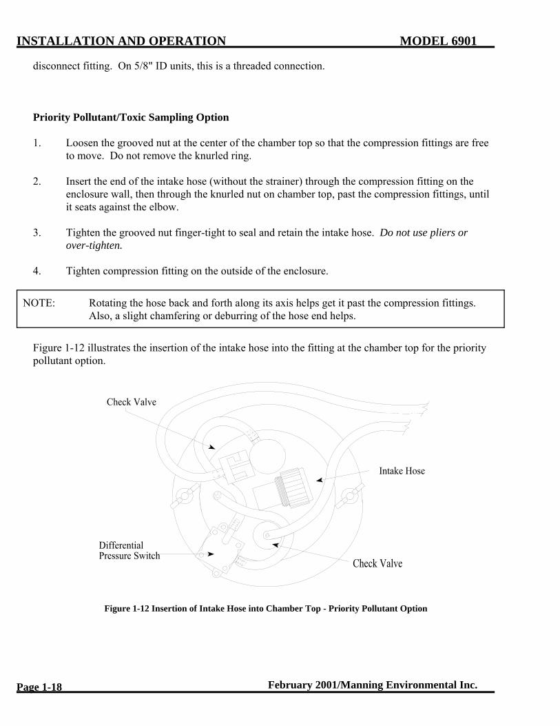
Priority Pollutant/Toxic Sampling Option
1. Loosen the grooved nut at the center of the chamber top so that the compression fittings are freeto move. Do not remove the knurled ring.
2. Insert the end of the intake hose (without the strainer) through the compression fitting on theenclosure wall, then through the knurled nut on chamber top, past the compression fittings, untilit seats against the elbow.
3. Tighten the grooved nut finger-tight to seal and retain the intake hose. Do not use pliers orover-tighten.
4. Tighten compression fitting on the outside of the enclosure.
NOTE: Rotating the hose back and forth along its axis helps get it past the compression fittings. Also, a slight chamfering or deburring of the hose end helps.
Figure 1-12 illustrates the insertion of the intake hose into the fitting at the chamber top for the prioritypollutant option.
Figure 1-12 Insertion of Intake Hose into Chamber Top - Priority Pollutant Option

MODEL 6901 INSTALLATION AND OPERATION
February 2001/Manning Environmental Inc. Page 1-19
Intake Hose Placement
Place the intake hose strainer directly in the channel flow, not in an eddy or at the edge of the flow. Inchannels with debris, provide deflection to prevent clogging of strainer holes. The weight supplied withthe intake hose is usually sufficient to prevent the intake from being pulled to the surface of a fastchannel.
The correct vertical position of the strainer depends on the type of sample being taken. Placing thestrainer at the bottom of the flow results in a heavier concentration of solids in the sample, while placingthe strainer at or near the top of the flow results in heavier concentration of oils, fats, and other floatingor suspended contaminants.
The intake hose should be positioned so the hose can drain between sample cycles and no low spotsexist which would trap water. Figure 1-13 shows correct and incorrect hose placement.
Manning provides hoses in standard lengths (10, 25, 50 and 100 feet). In some instances it is necessaryto cut the hose length down for a correct permanent installation. In these instances, remove theconnector from the hose, cut the hose and then reinstall the connector. To aid in the reinstallation of thehose onto the connector, use a heat gun to carefully warm up the hose end, and then expand the hoseend using a pair of round-nose pliers.
In installations where the temperature will drop below freezing for extended periods of time, coveringthe hose with insulation may be necessary to prevent icing. Shielding the hose from sunlight will helpprevent build-up of algae inside the hose.
Figure 1-13 Intake Hose Placement

INSTALLATION AND OPERATION MODEL 6901
February 2001/Manning Environmental Inc.Page 1-20
Figure 1-14 Flow-thru Cell Installation
Flow-thru Cell Sampling Option (Old Version)
1. Mount the flow-thru cell on the side of the enclosure using the hardware provided (the flow-thrucell can be ordered with either a left or right mount). See figure 1-14.
2. Loosen the knurled nut on the flow-thru cell elbow. Slip the intake hose through the nut until itseats against the elbow. Tighten the knurled nut. Do not use pliers or over-tighten.
3. Attach the incoming 1-1/2" pipe to the valve.
4. Secure the 3" flange to the drain line.
5. Adjust the valve so the flow does not exceed 50 gpm at 50 psi maximum.
NOTE: If the flow exceeds 50 gpm, back pressure will build up and the fluid will flow directly intothe chamber. If the flow is lower than 1 gpm, sample size will be irregular.
Flow-Thru Cell Sampling Option (Present Version)
See instructions that accompany the flow-thru cell.
RUNNING A TEST CYCLE

MODEL 6901 INSTALLATION AND OPERATION
February 2001/Manning Environmental Inc. Page 1-21
Manning recommends running a test cycle to assure proper operation and to become familiar with thevarious functions and modes of operation. Since the sampler type and number of bottles werepre-configured for the unit at the factory, run a test cycle before programming any operational modes intothe sampler.
1. Turn the main power switch on the central panel to the “ON” position.
2. If the multi-bottle option is being used, rotate the spout so it is over a bottle.
3. Submerge the strainer of the intake hose in a container of clean water. The amount of watershould be enough to keep the strainer covered completely for several test cycles.
4. Press the TEST CYCLE key, then the ENTER key on the keypad to initiate the test cycle.
SETTING THE SAMPLE SIZE
1. Remove the two wingnuts securing the chamber top and lift the chamber top slightly.
2. Twist the spiral (outer) tube so its opening aligns with the slit in the slotted (inner) tube at thelevel corresponding to desired sample volume. See Figure 1-15. Make sure the sleeve staysseated up against the bottom of the chamber top.
3. Replace the chamber top and verify the alignment with the graduations on the chamber.
4. Replace the wingnuts and tighten finger-tight, making sure all o-rings are evenly compressed andwill seal.
5. Activate a test cycle.
6 Measure the sample deposited.
7. Repeat steps 1 - 6 as needed to fine-tune sample volume.
NOTE: The sample can be collected in the containers, or the distribution assembly can beremoved and the sample collected in a beaker.

INSTALLATION AND OPERATION MODEL 6901
February 2001/Manning Environmental Inc.Page 1-22
Figure 1-15 Setting Sample Size
THE SAMPLING CYCLE
There are two types of sample events. The first is time-based. In this type a time interval is defined and thesampler places a sample in each bottle based on that time interval.
The second type of sample event is flow-based. In this type an external flowmeter provides one of two typesof signals: a contact closure when a specified amount of liquid has flowed past the measurement point; orwith the analog option, an analog signal proportional to flow rate.
Whether the sample event is triggered by a flowmeter or by a time interval, the actual sampling cycle is thesame. For the multi-bottle option, the first action is the advance of the spout to the next bottle. (For singlebottle samplers, this step is omitted.) Next, the sampler activates a solenoid underneath the measuringchamber which causes a bar to pinch the silicone discharge tubing (pinch tubing). This seals off the bottomof the chamber. Then the sampler turns the compressor on, which forces pressurized air into the chamberand through the intake hose to purge the line of any contents or obstructions. This is called the “purge.”When the purge is complete, the controller actuates valve(s) (one 4-way valve in AC units, two 3-wayvalves in DC units) which switches the vacuum side of the compressor to the chamber. The suction createddraws fluid into the chamber. When the chamber is filled a sensing device (either a differential pressureswitch or a magnetic float switch) signals the controller to switch back to purge. The fluid is purged to thespecified volume, the pinch solenoid is releases and then the fluid is depositedr into the sample container. Ifa full chamber is not sensed, the sampler makes another draw attempt. If after two attempts a full chamber isstill not sensed, the sampler stops the cycle until the next sample event.
If the multi-bottle option is being used, the distribution spout remains stationary until the next sample event. This delay prevents cross-contamination of the next sample.
SAMPLE RECOVERY

MODEL 6901 INSTALLATION AND OPERATION
February 2001/Manning Environmental Inc. Page 1-23
Immediate sample recovery is not required since the sampler will automatically shut down when the samplecontainer is full (single bottle only), or when the program is complete. However, sample analysis mayrequire quick recovery to maintain sample freshness or to add chemicals.
If the sample containers are to be left in the suspension plate, install the caps over the suspension collars. Then remove the suspension plate (with bottles) from the refrigerator. Lift the distribution assembly off thesuspension plate and place it on the wire racks mounted in the refrigerator.
It may be easier to remove the distribution assembly first, and then install the bottle caps. To seal the 350ml glass bottles, replace cap liners, place the caps on bottles, and put the collars in a safe place for later use.
EXTERNAL CONNECTIONS
DANGER: Turn the sampler off at the power switch and unplug the power supply before makingconnections. There is power on the terminal strip even with the power switch (circuitbreaker) off.
Injury can result if the power is present when connections are made.
External Connections To The Sampler Connecting external devices such as flowmeters to the sampler is accomplished by attaching wires tothe appropriate terminals on TB2, located in the back of the sampler. See Figure 1-16. On samplers withthe Analog option, a short pigtail is attached to TB2-5 and TB2-11 and routed through the upper water tightfitting on the right hand side of the sampler. On all other samplers, the pigtail is attached to TB2-9 andTB2-10 (Contact In). If local electrical wiring codes do not allow for the use of the pigtails, they can beremoved and wires can be attached directly to TB2 terminals through the watertight fitting. Below is adescription of the various input and output signals available at TB2:
Serial Out (TB2-1, TB2-6). On samplers equipped with the Serial Out option, data log information canbe downloaded to a computer or other serial device. See the *91 in the Programming Section for moreinformation. Signal ground is provided by TB2-6.
End of Sequence (TB2-3 to TB2-7). This is relay contact output that closes momentarily at the end ofa sampling program sequence. The relay contact is rated at 10VA.
Analog In (TB2-5 to TB2-11). On samplers equipped with the Analog Option, a 4-20mA signal from aflowmeter is connected to this input so that the sampler can be programmed to take flow-paced samples based off the signal. TB2-5 is the positive side and TB2-11 is the negative side. The connection will place 250 Ohm load on the current loop.
+5 Volts (TB2-4). This is a +5VDC output current limited to 100mA. It is provided for interfacingwith devices that require a logic pull-up signal.

INSTALLATION AND OPERATION MODEL 6901
February 2001/Manning Environmental Inc.Page 1-24
Note: In areas where there is the possibility of lighting activity, surge suppression devices should beinstalled to protect the sampler. This is especially important in current loops.
Signal Ground (TB2-6). This a signal ground point for use with Serial Out and Remote Start In.
Contact In (TB2-9 to TB2-10). This is an input signal from an external device such as a flowmeter fortriggering samples when the sampler is programmed one of the Flow (non-analog) programs. A “dry”contact or switch closure (resistance less than 500 Ohms) that stays closed for a minimum of 250milliseconds is required. If the input device uses a polarity-sensitive switching device, then the postiveside is connected to TB2-10 and the negative side to TB2-9. The external device’s output cannot beconnected to any other device besides the sampler (i.e., you cannot use one set of relay contacts totrigger two samplers).
Contact Out (TB2-8 to TB2-12). This is a relay output that closes momentarily at the end of a sample event (cycle). The relay contact is rated at 10VA.
Remote Start In (TB2-14). This is an input that allows a sampling program to be started by a remote device providing a momentary “dry” contact closure. This acts the same as pressing the <START> button on the keypad. The input requirements the same as for Contact In. If the input device uses a polarity-sensitive switching device, then the positive side is connected to TB2-14, and the negative side is connected to TB2-6. One sampler can remote start a second sampler by connecting SequenceComplete from the first sampler to Remote Start on the second sampler.
Alarm OptionConnections for the Alarm Option are covered in Appendix F.

MODEL 6901 INSTALLATION AND OPERATION
February 2001/Manning Environmental Inc. Page 1-25
Figure 1-16 External Connections/Interface

INSTALLATION AND OPERATION MODEL 6901
February 2001/Manning Environmental Inc.Page 1-26
THIS PAGE LEFT INTENTIONALLY BLANK

MODEL 6901 PROGRAMMING SECTION
February 2001/Manning Environmental Inc. Page 2-1
Programming
INTRODUCTION
The sampler is controlled by a microprocessor that can execute a wide variety of time and flow samplingsequences called Modes. Entries are made through a keypad (Figure 2-1) with prompts displayed on a 2line by 20 character back-lighted LCD (Liquid Crystal Display).
Current Version Older Version
Figure 2-1 Manning 6901 Keypads
SAMPLER CONFIGURATION
For the sampler to function properly, it must be set-up for the specific application in which it will be used. The *99 Function configures the sampler. Configuration defines multiple variables that do not usuallychange between different applications. These are such things as the type of sampler (single or multiplebottle), the number of bottles, and other factors like draw time, and purge time. Instructions forconfiguration of the sampler begin on page 2-7.
SAMPLING MODES
The sampler has two basic Modes: Time and Flow. (NOTE: While referred to as Flow Mode, the samplercan actuate based on signals from any external device. What device or why the device is supplying theclosure is transparent to the sampler. The sampler simply registers a contact closure, so actuation can occurbased on pH, ORP, Level, Flow, or other parameters. Time mode is based on a preset time period that mustpass before a sample is taken. Flow mode has two variants. The standard controller (contact closure

PROGRAMMING SECTION MODEL 6901
Page 2-2 February 2001/Manning Environmental Inc.
pass before a sample is taken. Flow mode has two variants. The standard controller (contact closureoption) allows sampling based on contact closures from an external device. The analog controller (4-20mAoption) allows sampling based on an analog signal totalized by the sampler's controller. All programs (orModes) available for the Model 6901 are based on either Time or Flow. Instructions for programming thedifferent Modes begin on page 2-17.
Multi-Bottle Sampling ModesAll of the programs or Modes can be used with multiple bottle samplers.
Single Bottle ModesAll General Programs (Basic Time and Flow Modes)*02 Time Interval Override Mode*04 Multiple Time Intervals Mode*05 Totalizing Analog Flow Mode*06 Totalizing Analog Level Mode

MODEL 6901 PROGRAMMING SECTION
February 2001/Manning Environmental Inc. Page 2-3
SECTION CONTENTSUTILITY & DISPLAY FUNCTIONS . . . . . . . . . . . . . . . . . . . . . . . . . . . . . . . . . . . . . . . . . . . . . . . . . . . . 2-5
<RESET> <RESET> . . . . . . . . . . . . . . . . . . . . . . . . . . . . . . . . . . . . . . . . . . . . . . . . . . . . . . . . . 2-5<TEST CYCLE> . . . . . . . . . . . . . . . . . . . . . . . . . . . . . . . . . . . . . . . . . . . . . . . . . . . . . . . . . . . . 2-5<BOTTLE ADV> . . . . . . . . . . . . . . . . . . . . . . . . . . . . . . . . . . . . . . . . . . . . . . . . . . . . . . . . . . . 2-5<CLEAR> . . . . . . . . . . . . . . . . . . . . . . . . . . . . . . . . . . . . . . . . . . . . . . . . . . . . . . . . . . . . . . . . . 2-5<CLOCK> . . . . . . . . . . . . . . . . . . . . . . . . . . . . . . . . . . . . . . . . . . . . . . . . . . . . . . . . . . . . . . . . . 2-5<DISPLAY> . . . . . . . . . . . . . . . . . . . . . . . . . . . . . . . . . . . . . . . . . . . . . . . . . . . . . . . . . . . . . . . 2-5* . . . . . . . . . . . . . . . . . . . . . . . . . . . . . . . . . . . . . . . . . . . . . . . . . . . . . . . . . . . . . . . . . . . . . . . . . 2-5EEEE . . . . . . . . . . . . . . . . . . . . . . . . . . . . . . . . . . . . . . . . . . . . . . . . . . . . . . . . . . . . . . . . . . . . . 2-5KEY NOT ACTIVE . . . . . . . . . . . . . . . . . . . . . . . . . . . . . . . . . . . . . . . . . . . . . . . . . . . . . . . . . 2-5POWER GLITCH . . . . . . . . . . . . . . . . . . . . . . . . . . . . . . . . . . . . . . . . . . . . . . . . . . . . . . . . . . . 2-6POWER FAILURE . . . . . . . . . . . . . . . . . . . . . . . . . . . . . . . . . . . . . . . . . . . . . . . . . . . . . . . . . . 2-6SAMPLER READY . . . . . . . . . . . . . . . . . . . . . . . . . . . . . . . . . . . . . . . . . . . . . . . . . . . . . . . . . 2-6
DISPLAY INFORMATION . . . . . . . . . . . . . . . . . . . . . . . . . . . . . . . . . . . . . . . . . . . . . . . . . . . . . . . . . . . . 2-7TIME OF DAY . . . . . . . . . . . . . . . . . . . . . . . . . . . . . . . . . . . . . . . . . . . . . . . . . . . . . . . . . . . . . 2-7PROGRAM . . . . . . . . . . . . . . . . . . . . . . . . . . . . . . . . . . . . . . . . . . . . . . . . . . . . . . . . . . . . . . . . 2-7PROGRAM STATUS . . . . . . . . . . . . . . . . . . . . . . . . . . . . . . . . . . . . . . . . . . . . . . . . . . . . . . . . 2-7
Sampler Ready . . . . . . . . . . . . . . . . . . . . . . . . . . . . . . . . . . . . . . . . . . . . . . . . . . . . . . . . 2-7Programming . . . . . . . . . . . . . . . . . . . . . . . . . . . . . . . . . . . . . . . . . . . . . . . . . . . . . . . . . 2-7Active Program . . . . . . . . . . . . . . . . . . . . . . . . . . . . . . . . . . . . . . . . . . . . . . . . . . . . . . . 2-7Configuration . . . . . . . . . . . . . . . . . . . . . . . . . . . . . . . . . . . . . . . . . . . . . . . . . . . . . . . . . 2-7Operational . . . . . . . . . . . . . . . . . . . . . . . . . . . . . . . . . . . . . . . . . . . . . . . . . . . . . . . . . . . 2-7
DISPLAY BOTTOM LINE STATUS INFORMATION . . . . . . . . . . . . . . . . . . . . . . . . . . . . . 2-7*50 DISPLAY SOFTWARE VERSION . . . . . . . . . . . . . . . . . . . . . . . . . . . . . . . . . . . . . . . . . . 2-9
SAMPLER CONFIGURATION FUNCTIONS . . . . . . . . . . . . . . . . . . . . . . . . . . . . . . . . . . . . . . . . . . . . 2-10*99 . . . . . . . . . . . . . . . . . . . . . . . . . . . . . . . . . . . . . . . . . . . . . . . . . . . . . . . . . . . . . . . . . . . . . . 2-10*91 Data Logging . . . . . . . . . . . . . . . . . . . . . . . . . . . . . . . . . . . . . . . . . . . . . . . . . . . . . . . . . . 2-13
ID MENU . . . . . . . . . . . . . . . . . . . . . . . . . . . . . . . . . . . . . . . . . . . . . . . . . . . . . . . . . . . 2-13VIEW MENU . . . . . . . . . . . . . . . . . . . . . . . . . . . . . . . . . . . . . . . . . . . . . . . . . . . . . . . 2-14EXIT MENU . . . . . . . . . . . . . . . . . . . . . . . . . . . . . . . . . . . . . . . . . . . . . . . . . . . . . . . . 2-17DOWNLOAD MENU . . . . . . . . . . . . . . . . . . . . . . . . . . . . . . . . . . . . . . . . . . . . . . . . . 2-17CLEAR MENU . . . . . . . . . . . . . . . . . . . . . . . . . . . . . . . . . . . . . . . . . . . . . . . . . . . . . . 2-18*14 CLEAR LOG DATA . . . . . . . . . . . . . . . . . . . . . . . . . . . . . . . . . . . . . . . . . . . . . . 2-19
ANALOG OPTION PROGRAMMING . . . . . . . . . . . . . . . . . . . . . . . . . . . . . . . . . . . . . . . . . . . . . . . . . . 2-20Totalizing . . . . . . . . . . . . . . . . . . . . . . . . . . . . . . . . . . . . . . . . . . . . . . . . . . . . . . . . . . . . . . . . . 2-20
*08 Analog Display Routine . . . . . . . . . . . . . . . . . . . . . . . . . . . . . . . . . . . . . . . . . . . . 2-21
ADD-ON PROGRAMMING FUNCTIONS . . . . . . . . . . . . . . . . . . . . . . . . . . . . . . . . . . . . . . . . . . . . . . . 2-23Multiple Bottles per Sampling Event . . . . . . . . . . . . . . . . . . . . . . . . . . . . . . . . . . . . . . . . . . . 2-23Multiple Samples per Bottle . . . . . . . . . . . . . . . . . . . . . . . . . . . . . . . . . . . . . . . . . . . . . . . . . . 2-24Delay Start - Time . . . . . . . . . . . . . . . . . . . . . . . . . . . . . . . . . . . . . . . . . . . . . . . . . . . . . . . . . . 2-25

PROGRAMMING SECTION MODEL 6901
Page 2-4 February 2001/Manning Environmental Inc.
*16 Midnight Switch (Bottle Advance) . . . . . . . . . . . . . . . . . . . . . . . . . . . . . . . . . . . . . . . . . . 2-26
GENERAL PROGRAMS . . . . . . . . . . . . . . . . . . . . . . . . . . . . . . . . . . . . . . . . . . . . . . . . . . . . . . . . . . . . . 2-27Time Mode - * Start . . . . . . . . . . . . . . . . . . . . . . . . . . . . . . . . . . . . . . . . . . . . . . . . . . . . . . . . . 2-27Time Mode - Single Time Interval . . . . . . . . . . . . . . . . . . . . . . . . . . . . . . . . . . . . . . . . . . . . . 2-28*15 Time Mode - Active Sampling Period . . . . . . . . . . . . . . . . . . . . . . . . . . . . . . . . . . . . . . . 2-29Flow Mode . . . . . . . . . . . . . . . . . . . . . . . . . . . . . . . . . . . . . . . . . . . . . . . . . . . . . . . . . . . . . . . . 2-31Flow Mode - Pulse Accumulation . . . . . . . . . . . . . . . . . . . . . . . . . . . . . . . . . . . . . . . . . . . . . . 2-32
MULTI-BOTTLE SAMPLING PROGRAMS . . . . . . . . . . . . . . . . . . . . . . . . . . . . . . . . . . . . . . . . . . . . . 2-33*01 Flow Mode - Independently Timed Spout Advance . . . . . . . . . . . . . . . . . . . . . . . . . . . . . 2-33*02 Flow Mode - Time Interval Override . . . . . . . . . . . . . . . . . . . . . . . . . . . . . . . . . . . . . . . . 2-34*03 Flow Mode - External Event . . . . . . . . . . . . . . . . . . . . . . . . . . . . . . . . . . . . . . . . . . . . . . . 2-35*04 Time Mode - Multiple Intervals . . . . . . . . . . . . . . . . . . . . . . . . . . . . . . . . . . . . . . . . . . . . 2-36*07 Flow Mode - Time Interval Delay . . . . . . . . . . . . . . . . . . . . . . . . . . . . . . . . . . . . . . . . . . 2-38
ANALOG SAMPLING PROGRAMS . . . . . . . . . . . . . . . . . . . . . . . . . . . . . . . . . . . . . . . . . . . . . . . . . . . 2-39*05 Flow Mode - Totalizing Analog . . . . . . . . . . . . . . . . . . . . . . . . . . . . . . . . . . . . . . . . . . . . 2-39*06 Analog Level Mode . . . . . . . . . . . . . . . . . . . . . . . . . . . . . . . . . . . . . . . . . . . . . . . . . . . . . 2-41*09 Hydrologic Level Event Mode . . . . . . . . . . . . . . . . . . . . . . . . . . . . . . . . . . . . . . . . . . . . . 2-44
MULTI-BOTTLE FLOW COMPOSITE PROGRAMS . . . . . . . . . . . . . . . . . . . . . . . . . . . . . . . . . . . . . . 2-48*10 Flow Mode - Multiple Bottle Composite . . . . . . . . . . . . . . . . . . . . . . . . . . . . . . . . . . . . . 2-48*11 Flow Mode - Totalizing Analog Multiple Bottle Composite . . . . . . . . . . . . . . . . . . . . . . 2-50*12 Flow Mode - Multiple Bottle Composite with Bottle Groups . . . . . . . . . . . . . . . . . . . . . 2-52*13 Flow Mode - Totalizing Analog Multiple Bottle Composite with Bottle Groups . . . . . . 2-55

MODEL 6901 PROGRAMMING SECTION
February 2001/Manning Environmental Inc. Page 2-5
UTILITY & DISPLAY FUNCTIONSKey Function
<RESET> <RESET> Functions as a Reset (a soft boot in computer terms) for the sampler and clearsthe current program mode.
<TEST CYCLE> Allows the user to check the sampler for mechanical operation by taking aphysical sample. The operator is prompted for the number of Test Cycles (1-99,with the default being 1) to run. Test Cycle can also be used for taking animmediate (grab) sample.
<BOTTLE ADVANCE> With Multi-bottle samplers, advances the spout clockwise 1 bottle each time thekey is pressed momentarily. If the key is held down, the spout will continue tobe advanced until the key is released. This function does not work when aprogram is running.
<CLEAR> Clears invalid or incorrect entries before <ENTER> has been pressed. Alsoallows the user to step the cursor back 1 movement, clearing entries each timethe key is pressed.
<CLOCK> Sets the time on the sampler’s internal clock.. To set the time, the sampler mustnot be running a program(the display reads SAMPLER READY). Press<CLOCK> , enter the time and then press <ENTER>. NOTE: All times areentered and displayed in 24 hour HH:MM format. For example, 6 hours wouldbe entered as 0600 and a real time of 3:30 p.m. would be displayed as 15:30.
<DISPLAY> Shows current program or configuration information. The informationdisplayed depends on whether the sampler is running a program or not. If thesampler is not running a program (the display reads SAMPLER READY),pressing <DISPLAY> will show the configuration settings input in *99. If theuser is in a programmed mode (e.g. a TIME, FLOW, or * Mode), pressing<DISPLAY> will show the current time, spout position(if multi-bottle) , andother information specific to the current mode. NOTE: See Appendix B for aLogic Map of the Programming Modes and what displays are active when theDisplay key is pressed.
* Used to program Star Modes.
EEEE Indicates an error condition has occurred. Press CLEAR to reset, and re-enterthe data.
KEY NOT ACTIVE Indicates the key pressed is not active at the current time. For example, pressingan number key when the display reads SAMPLER READY will cause thesampler to display the KEY NOT ACTIVE message momentarily.

PROGRAMMING SECTION MODEL 6901
Page 2-6 February 2001/Manning Environmental Inc.
POWER GLITCH This is displayed momentarily when input power to the sampler controller momentarily goes dips(goes low and then recovers). This may occur at thebeginning of a sample cycle if input power is low. This can also indicate that asampler component is drawing an excessive amount of current.
POWER FAILURE This is displayed momentarily when input power to the sampler goes low andstays low or is turned off.
SAMPLER READY This is displayed when the sampler is on and not in an sampling program.

MODEL 6901 PROGRAMMING SECTION
February 2001/Manning Environmental Inc. Page 2-1
Programming
INTRODUCTION
The sampler is controlled by a microprocessor that can execute a wide variety of time and flow samplingsequences called Modes. Entries are made through a keypad (Figure 2-1) with prompts displayed on a 2line by 20 character back-lighted LCD (Liquid Crystal Display).
Current Version Older Version
Figure 2-1 Manning 6901 Keypads
SAMPLER CONFIGURATION
For the sampler to function properly, it must be set-up for the specific application in which it will be used. The *99 Function configures the sampler. Configuration defines multiple variables that do not usuallychange between different applications. These are such things as the type of sampler (single or multiplebottle), the number of bottles, and other factors like draw time, and purge time. Instructions forconfiguration of the sampler begin on page 2-7.
SAMPLING MODES
The sampler has two basic Modes: Time and Flow. (NOTE: While referred to as Flow Mode, the samplercan actuate based on signals from any external device. What device or why the device is supplying theclosure is transparent to the sampler. The sampler simply registers a contact closure, so actuation can occurbased on pH, ORP, Level, Flow, or other parameters. Time mode is based on a preset time period that must

PROGRAMMING SECTION MODEL 6901
Page 2-2 February 2001/Manning Environmental Inc.
pass before a sample is taken. Flow mode has two variants. The standard controller (contact closureoption) allows sampling based on contact closures from an external device. The analog controller (4-20mAoption) allows sampling based on an analog signal totalized by the sampler's controller. All programs (orModes) available for the Model 6901 are based on either Time or Flow. Instructions for programming thedifferent Modes begin on page 2-17.
Multi-Bottle Sampling ModesAll of the programs or Modes can be used with multiple bottle samplers.
Single Bottle ModesAll General Programs (Basic Time and Flow Modes)*02 Time Interval Override Mode*04 Multiple Time Intervals Mode*05 Totalizing Analog Flow Mode*06 Totalizing Analog Level Mode

MODEL 6901 PROGRAMMING SECTION
February 2001/Manning Environmental Inc. Page 2-3
SECTION CONTENTSUTILITY & DISPLAY FUNCTIONS . . . . . . . . . . . . . . . . . . . . . . . . . . . . . . . . . . . . . . . . . . . . . . . . . . . . 2-5
<RESET> <RESET> . . . . . . . . . . . . . . . . . . . . . . . . . . . . . . . . . . . . . . . . . . . . . . . . . . . . . . . . . 2-5<TEST CYCLE> . . . . . . . . . . . . . . . . . . . . . . . . . . . . . . . . . . . . . . . . . . . . . . . . . . . . . . . . . . . . 2-5<BOTTLE ADV> . . . . . . . . . . . . . . . . . . . . . . . . . . . . . . . . . . . . . . . . . . . . . . . . . . . . . . . . . . . 2-5<CLEAR> . . . . . . . . . . . . . . . . . . . . . . . . . . . . . . . . . . . . . . . . . . . . . . . . . . . . . . . . . . . . . . . . . 2-5<CLOCK> . . . . . . . . . . . . . . . . . . . . . . . . . . . . . . . . . . . . . . . . . . . . . . . . . . . . . . . . . . . . . . . . . 2-5<DISPLAY> . . . . . . . . . . . . . . . . . . . . . . . . . . . . . . . . . . . . . . . . . . . . . . . . . . . . . . . . . . . . . . . 2-5* . . . . . . . . . . . . . . . . . . . . . . . . . . . . . . . . . . . . . . . . . . . . . . . . . . . . . . . . . . . . . . . . . . . . . . . . . 2-5EEEE . . . . . . . . . . . . . . . . . . . . . . . . . . . . . . . . . . . . . . . . . . . . . . . . . . . . . . . . . . . . . . . . . . . . . 2-5KEY NOT ACTIVE . . . . . . . . . . . . . . . . . . . . . . . . . . . . . . . . . . . . . . . . . . . . . . . . . . . . . . . . . 2-5POWER GLITCH . . . . . . . . . . . . . . . . . . . . . . . . . . . . . . . . . . . . . . . . . . . . . . . . . . . . . . . . . . . 2-6POWER FAILURE . . . . . . . . . . . . . . . . . . . . . . . . . . . . . . . . . . . . . . . . . . . . . . . . . . . . . . . . . . 2-6SAMPLER READY . . . . . . . . . . . . . . . . . . . . . . . . . . . . . . . . . . . . . . . . . . . . . . . . . . . . . . . . . 2-6
DISPLAY INFORMATION . . . . . . . . . . . . . . . . . . . . . . . . . . . . . . . . . . . . . . . . . . . . . . . . . . . . . . . . . . . . 2-7TIME OF DAY . . . . . . . . . . . . . . . . . . . . . . . . . . . . . . . . . . . . . . . . . . . . . . . . . . . . . . . . . . . . . 2-7PROGRAM . . . . . . . . . . . . . . . . . . . . . . . . . . . . . . . . . . . . . . . . . . . . . . . . . . . . . . . . . . . . . . . . 2-7PROGRAM STATUS . . . . . . . . . . . . . . . . . . . . . . . . . . . . . . . . . . . . . . . . . . . . . . . . . . . . . . . . 2-7
Sampler Ready . . . . . . . . . . . . . . . . . . . . . . . . . . . . . . . . . . . . . . . . . . . . . . . . . . . . . . . . 2-7Programming . . . . . . . . . . . . . . . . . . . . . . . . . . . . . . . . . . . . . . . . . . . . . . . . . . . . . . . . . 2-7Active Program . . . . . . . . . . . . . . . . . . . . . . . . . . . . . . . . . . . . . . . . . . . . . . . . . . . . . . . 2-7Configuration . . . . . . . . . . . . . . . . . . . . . . . . . . . . . . . . . . . . . . . . . . . . . . . . . . . . . . . . . 2-7Operational . . . . . . . . . . . . . . . . . . . . . . . . . . . . . . . . . . . . . . . . . . . . . . . . . . . . . . . . . . . 2-7
DISPLAY BOTTOM LINE STATUS INFORMATION . . . . . . . . . . . . . . . . . . . . . . . . . . . . . 2-7*50 DISPLAY SOFTWARE VERSION . . . . . . . . . . . . . . . . . . . . . . . . . . . . . . . . . . . . . . . . . . 2-9
SAMPLER CONFIGURATION FUNCTIONS . . . . . . . . . . . . . . . . . . . . . . . . . . . . . . . . . . . . . . . . . . . . 2-10*99 . . . . . . . . . . . . . . . . . . . . . . . . . . . . . . . . . . . . . . . . . . . . . . . . . . . . . . . . . . . . . . . . . . . . . . 2-10*91 Data Logging . . . . . . . . . . . . . . . . . . . . . . . . . . . . . . . . . . . . . . . . . . . . . . . . . . . . . . . . . . 2-13
ID MENU . . . . . . . . . . . . . . . . . . . . . . . . . . . . . . . . . . . . . . . . . . . . . . . . . . . . . . . . . . . 2-13VIEW MENU . . . . . . . . . . . . . . . . . . . . . . . . . . . . . . . . . . . . . . . . . . . . . . . . . . . . . . . 2-14EXIT MENU . . . . . . . . . . . . . . . . . . . . . . . . . . . . . . . . . . . . . . . . . . . . . . . . . . . . . . . . 2-17DOWNLOAD MENU . . . . . . . . . . . . . . . . . . . . . . . . . . . . . . . . . . . . . . . . . . . . . . . . . 2-17CLEAR MENU . . . . . . . . . . . . . . . . . . . . . . . . . . . . . . . . . . . . . . . . . . . . . . . . . . . . . . 2-18*14 CLEAR LOG DATA . . . . . . . . . . . . . . . . . . . . . . . . . . . . . . . . . . . . . . . . . . . . . . 2-19
ANALOG OPTION PROGRAMMING . . . . . . . . . . . . . . . . . . . . . . . . . . . . . . . . . . . . . . . . . . . . . . . . . . 2-20Totalizing . . . . . . . . . . . . . . . . . . . . . . . . . . . . . . . . . . . . . . . . . . . . . . . . . . . . . . . . . . . . . . . . . 2-20
*08 Analog Display Routine . . . . . . . . . . . . . . . . . . . . . . . . . . . . . . . . . . . . . . . . . . . . 2-21
ADD-ON PROGRAMMING FUNCTIONS . . . . . . . . . . . . . . . . . . . . . . . . . . . . . . . . . . . . . . . . . . . . . . . 2-23Multiple Bottles per Sampling Event . . . . . . . . . . . . . . . . . . . . . . . . . . . . . . . . . . . . . . . . . . . 2-23Multiple Samples per Bottle . . . . . . . . . . . . . . . . . . . . . . . . . . . . . . . . . . . . . . . . . . . . . . . . . . 2-24Delay Start - Time . . . . . . . . . . . . . . . . . . . . . . . . . . . . . . . . . . . . . . . . . . . . . . . . . . . . . . . . . . 2-25

PROGRAMMING SECTION MODEL 6901
Page 2-4 February 2001/Manning Environmental Inc.
*16 Midnight Switch (Bottle Advance) . . . . . . . . . . . . . . . . . . . . . . . . . . . . . . . . . . . . . . . . . . 2-26
GENERAL PROGRAMS . . . . . . . . . . . . . . . . . . . . . . . . . . . . . . . . . . . . . . . . . . . . . . . . . . . . . . . . . . . . . 2-27Time Mode - * Start . . . . . . . . . . . . . . . . . . . . . . . . . . . . . . . . . . . . . . . . . . . . . . . . . . . . . . . . . 2-27Time Mode - Single Time Interval . . . . . . . . . . . . . . . . . . . . . . . . . . . . . . . . . . . . . . . . . . . . . 2-28*15 Time Mode - Active Sampling Period . . . . . . . . . . . . . . . . . . . . . . . . . . . . . . . . . . . . . . . 2-29Flow Mode . . . . . . . . . . . . . . . . . . . . . . . . . . . . . . . . . . . . . . . . . . . . . . . . . . . . . . . . . . . . . . . . 2-31Flow Mode - Pulse Accumulation . . . . . . . . . . . . . . . . . . . . . . . . . . . . . . . . . . . . . . . . . . . . . . 2-32
MULTI-BOTTLE SAMPLING PROGRAMS . . . . . . . . . . . . . . . . . . . . . . . . . . . . . . . . . . . . . . . . . . . . . 2-33*01 Flow Mode - Independently Timed Spout Advance . . . . . . . . . . . . . . . . . . . . . . . . . . . . . 2-33*02 Flow Mode - Time Interval Override . . . . . . . . . . . . . . . . . . . . . . . . . . . . . . . . . . . . . . . . 2-34*03 Flow Mode - External Event . . . . . . . . . . . . . . . . . . . . . . . . . . . . . . . . . . . . . . . . . . . . . . . 2-35*04 Time Mode - Multiple Intervals . . . . . . . . . . . . . . . . . . . . . . . . . . . . . . . . . . . . . . . . . . . . 2-36*07 Flow Mode - Time Interval Delay . . . . . . . . . . . . . . . . . . . . . . . . . . . . . . . . . . . . . . . . . . 2-38
ANALOG SAMPLING PROGRAMS . . . . . . . . . . . . . . . . . . . . . . . . . . . . . . . . . . . . . . . . . . . . . . . . . . . 2-39*05 Flow Mode - Totalizing Analog . . . . . . . . . . . . . . . . . . . . . . . . . . . . . . . . . . . . . . . . . . . . 2-39*06 Analog Level Mode . . . . . . . . . . . . . . . . . . . . . . . . . . . . . . . . . . . . . . . . . . . . . . . . . . . . . 2-41*09 Hydrologic Level Event Mode . . . . . . . . . . . . . . . . . . . . . . . . . . . . . . . . . . . . . . . . . . . . . 2-44
MULTI-BOTTLE FLOW COMPOSITE PROGRAMS . . . . . . . . . . . . . . . . . . . . . . . . . . . . . . . . . . . . . . 2-48*10 Flow Mode - Multiple Bottle Composite . . . . . . . . . . . . . . . . . . . . . . . . . . . . . . . . . . . . . 2-48*11 Flow Mode - Totalizing Analog Multiple Bottle Composite . . . . . . . . . . . . . . . . . . . . . . 2-50*12 Flow Mode - Multiple Bottle Composite with Bottle Groups . . . . . . . . . . . . . . . . . . . . . 2-52*13 Flow Mode - Totalizing Analog Multiple Bottle Composite with Bottle Groups . . . . . . 2-55

MODEL 6901 PROGRAMMING SECTION
February 2001/Manning Environmental Inc. Page 2-5
UTILITY & DISPLAY FUNCTIONSKey Function
<RESET> <RESET> Functions as a Reset (a soft boot in computer terms) for the sampler and clearsthe current program mode.
<TEST CYCLE> Allows the user to check the sampler for mechanical operation by taking aphysical sample. The operator is prompted for the number of Test Cycles (1-99,with the default being 1) to run. Test Cycle can also be used for taking animmediate (grab) sample.
<BOTTLE ADVANCE> With Multi-bottle samplers, advances the spout clockwise 1 bottle each time thekey is pressed momentarily. If the key is held down, the spout will continue tobe advanced until the key is released. This function does not work when aprogram is running.
<CLEAR> Clears invalid or incorrect entries before <ENTER> has been pressed. Alsoallows the user to step the cursor back 1 movement, clearing entries each timethe key is pressed.
<CLOCK> Sets the time on the sampler’s internal clock.. To set the time, the sampler mustnot be running a program(the display reads SAMPLER READY). Press<CLOCK> , enter the time and then press <ENTER>. NOTE: All times areentered and displayed in 24 hour HH:MM format. For example, 6 hours wouldbe entered as 0600 and a real time of 3:30 p.m. would be displayed as 15:30.
<DISPLAY> Shows current program or configuration information. The informationdisplayed depends on whether the sampler is running a program or not. If thesampler is not running a program (the display reads SAMPLER READY),pressing <DISPLAY> will show the configuration settings input in *99. If theuser is in a programmed mode (e.g. a TIME, FLOW, or * Mode), pressing<DISPLAY> will show the current time, spout position(if multi-bottle) , andother information specific to the current mode. NOTE: See Appendix B for aLogic Map of the Programming Modes and what displays are active when theDisplay key is pressed.
* Used to program Star Modes.
EEEE Indicates an error condition has occurred. Press CLEAR to reset, and re-enterthe data.
KEY NOT ACTIVE Indicates the key pressed is not active at the current time. For example, pressingan number key when the display reads SAMPLER READY will cause thesampler to display the KEY NOT ACTIVE message momentarily.

PROGRAMMING SECTION MODEL 6901
Page 2-6 February 2001/Manning Environmental Inc.
POWER GLITCH This is displayed momentarily when input power to the sampler controller momentarily goes dips(goes low and then recovers). This may occur at thebeginning of a sample cycle if input power is low. This can also indicate that asampler component is drawing an excessive amount of current.
POWER FAILURE This is displayed momentarily when input power to the sampler goes low andstays low or is turned off.
SAMPLER READY This is displayed when the sampler is on and not in an sampling program.

MODEL 6901 PROGRAMMING SECTION
February 2001/Manning Environmental Inc. Page 2-7
DISPLAY INFORMATIONThe Manning sampler is capable of displaying a wealth of information through the 2 line by 20 characterdisplay. The following describes the functions and how they can be of benefit to the user:
TIME OF DAY The time of day is always displayed in the bottom right hand corner of the display. Theformat is a 24 hour clock HH:MM:SS. If the display is not counting down the seconds,the controller may have quit functioning. Press <RESET> <RESET> to warm boot thesystem. If this does not clear the problem, please call Manning at 1-800-863-9337.
PROGRAM The bottom left hand corner of the display is used for indicating miscellaneousSTATUS program and functional information. The information displayed here varies depending
on the operational status of the active program. The following highlights the function ofthe display in different modes:
Sampler Ready: Shows time of day in HH:MM format (24 hour clock)
Programming: In programming situations, the display is used for enteringthe data required by the particular mode that is beingprogrammed.
Active Program: The information displayed depends on the type of programand the status of that program. When a time is shown inthis section of the display it is signified by a flashing colon. The time shown may signify time to sample, time override,purge time, draw time, or other times associated with theprogram. All time displays are in HH:MM format, exceptfor configuration function times (draw time, purge time,measure time, deposit time) and *07 DELAYED SAMPLEEVENT MODE which are shown in MM:SS format. Nontime displays are characterized by a 4 digit display whichdoes not posses a flashing cursor. The information relayedhere may be the sample number or the bottle numberdepending on the active program and its state.
Configuration: See Appendix B for more information.
Operational: See Appendix B for more information.
Display Bottom Line Status Information
The information displayed on the bottom line of the 2 by 20 line display is divided into three fields withone space between fields. These fields proved the operator with information about the status of the sampler. The first field (positions 1 thru 5) is used for a variety of information depending on the active program. The second field (positions 6 thru 11) is used to display status information. Field 2 is detailed below. Field3 (positions 13 thru 20) displays the real time clock in a HH:MM:SS format.

PROGRAMMING SECTION MODEL 6901
Page 2-8 February 2001/Manning Environmental Inc.
1 2 3 4 5 6 7 8 9 10 11 12 13 14 15 16 17 18 19 20
S A M P L E R R E A D Y
FIELD 1 FIELD 2 FIELD 3
Sampler 2 x 20 LCD Display
Field 2
Field 2 consists of 6 character positions (6,7,8,9,10,11). The matrix below details what characters appear inwhat positions. Each position is either blank or contains one character.
Field 6 7 8 9 10 11
Character
MidnightSwitch *16
M
Active TimePeriod *15
A
Multi-Sample
S
Multi-Bottle
B
Delay Start-Time
D
Delay Start-Pulse
P
Flow F
Analog A
Time T
Here are some examples of the Field 2 data:

MODEL 6901 PROGRAMMING SECTION
February 2001/Manning Environmental Inc. Page 2-9
Display on LCD Explanation
SAMPLER READY10:04M 10:04:00
The sampler is not in a active sampling program, but the MidnightSwitch (*16) has been set on. (“M” in 6th position of second line)
TIME01:00 AS T 10:04:10
The sample is programmed in a Time sampling program, has anActive Time period set, and has been programmed for MultipleSamples per Bottle.
FLOW (*05)01:00 A 10:04:20
The sampler is in the Analog Totalizing sampling program (*05).
*50 DISPLAY SOFTWARE VERSION
This program allows the operator to view the sampler software version (date). The software version is alsomomentarily displayed whenever the sampler is Warm-Booted by pressing <RESET> twice.
Display on LCD Explanation
SAMPLER READY10:04 10:04:00
This display shows the sampler is ready to program. It displays thecurrent time. Press the <*> key.
ENTER * MODE _ _ 10:04:10
Prompts the user to enter a program or configuration function. Press 50 and <ENTER> to display the sampler software version(date).
VERSION 7/15/980050 10:04:20
The display will change to show the version(date) of the softwarefor 3 seconds.
SAMPLER READY10:04 10:04:30
The display then changes back to the SAMPLER READY promptand is ready for further programming.

PROGRAMMING SECTION MODEL 6901
Page 2-10 February 2001/Manning Environmental Inc.
SAMPLER CONFIGURATION FUNCTIONS
*99*99 allows the user to set the sampler's configuration. For proper operation, it is critical the unit is correctlyconfigured. The memory comes preset with the sampler's defaults. These defaults can be reviewed orchanged by entering the configuration mode (explanations and step-by-step instructions are given below). Once entries have been made in *99, re-entering the configuration mode is not necessary unless changes inthe data are needed.
Display on LCD Explanation
SAMPLER READY10:04 10:04:00
This display shows the sampler is ready to program. It displays thecurrent time. From here the user can enter any TIME, FLOW, or *Mode. Press the * key to access the * Mode.
ENTER * MODE? _ _ 10:04:00
Prompts the user to enter either a program or the configurationfunction. Press 99 and <ENTER> to configure the sampler.
SAMPLER SETTING? __ 10:04:00
Sets the sampler to a specific type of operation or bottleconfiguration:1 = Single Bottle2 = Multi-BottleEnter the desired configuration and press <ENTER>. The defaultis 2 (Multi-bottle sampler).
# OF BOTTLES? __ __ 10:04:00
Sets the number of bottles (2,3,4,6,8,12, or 24) being used by thesampler in multi-bottle mode. If 1 was selected for the SAMPLERSETTING above, this prompt is bypassed. Input the number ofbottles and press <ENTER>. The default is 24.
PURGE TIME? __ __ 10:04:00
Length of time (3-99 seconds) the intake line is purged before asample is taken. Press <ENTER> to accept the default purge timeor input a new 2-digit number. If air bubbles are not coming out ofthe intake line, or if fluid is visible in the line after the purge hasbeen completed, increase the purge time. The default is 9 seconds.

MODEL 6901 PROGRAMMING SECTION
February 2001/Manning Environmental Inc. Page 2-11
DRAW TIME? __ __ __ 10:04:00
Time window (4-150 seconds) during which a sample is drawn.Press <ENTER> to accept the displayed draw time or input a newdraw time as a 3-digit number and then press <ENTER>. If thesample fluid does not reach the liquid sensor, causing the samplerto move from drawing to measuring the sampler, increase the drawtime. The default is 30 seconds. NOTE: This time is the maximumtime that the sampler will attempt to draw a sample. If the fluidsensor has not been triggered(i.e., the measuring chamber is notfilled), the sampler will purge the line and attempt to draw thesample again. If a sample cannot be taken after the second drawtime has expired, then the sampler will log a missed sample.
MEASURE TIME? __ __ 10:04:00
Time window (3-99 seconds) during which the sample is purged tothe specified volume. Press ENTER to accept the measure timewhich is displayed or input a new measure time as a 2 digit numberand then press ENTER. If the sample size is not purging to thespecified volume, the measure time needs to be increased. Thedefault is 9 seconds.
DEPOSIT TIME? __ __ 10:04:00
Time window (3-99 seconds) during which the sample is depositedin the bottle. Press ENTER to accept the time shown or input anew time as a 2 digit number and press ENTER. A longer deposittime will force the fluid into the bottle quicker. If the samplecontainer is being filled almost completely, then the deposit timeshould be decreased to allow the fluid to gravity-feed into thecontainer. The default is 8 seconds.
# OF CHAMBER FILLS? __ 10:04:00
The number of times (1-4) the 500ml measuring chamber is filledand deposited into a bottle, per sampling event. (Only onechamber fill is performed during a test cycle). Press ENTER toaccept the number of chamber fills shown or input a new numberof chamber fills and press the ENTER key. The default is 1.
AUTO RESTART? __ 10:04:00
Sets the auto restart mode: 0 - No auto restart; 1 - auto restartactivated. This option will restart the sampler and continue theprogram that was running, if power fails. It stores parameters,ensures orderly shutdown, and stores enough energy to completeany stepper motor steps in progress. If 0- no auto restart is selected,the sampler will reset when The default is 1- auto restart activated.
TEST CYCLE MODE? __ 10:04:00
Sets the test cycle mode. Press <ENTER> to accept the default orinput a new number corresponding to the manner in which testsamples are to be taken:0 - Only when the sampler is not running a program.1 - In a program, but the sample does not count in the program.2 - In a program, and the sample counts in the program.The default is 1.

PROGRAMMING SECTION MODEL 6901
Page 2-12 February 2001/Manning Environmental Inc.
KEYPAD BEEP MODE? __ 10:04:00
Sets whether the keypad beeps when keys are pressed:0 - No beep 1 - Will beep. Press <ENTER> to accept the setting shown, or input a newnumber and press <ENTER>. This also controls what is displayedduring an analog program if the unit has the optional analogcontroller. These displays are explained in detail in the AnalogProgramming Section on page 2-8. The default is 1.
BACKLIGHT MODE? __ 10:04:00
Sets whether the display backlights:0 - Backlight is never on. This is good if power conversation is
critical.1 - Backlight comes on when a key is pressed. The light will
automatically turn off after 10 seconds if another key is notpressed.
2- Backlight comes on when a key is pressed and also at the startof a sampling cycle. The light will automatically turn off after10 seconds if another key is not pressed or another samplingcycle is not initiated.
3- Backlight is always on. This choice will quickly run down abattery.
The default is 1.
ENTER PASSWORD__ __ __ __ 10:04:00
Creates a password to stop unauthorized access. There are 2options:A. Press <ENTER> to accept no password - 0000 (default
shown)B. Enter a 4-digit number at the prompt and press <ENTER>.
The user will be prompted to verify the password. Enterthe same 4 digits and press <ENTER>. This sets thepassword. RECORD the numbers. To change a password,enter *99 mode and input the 4 digit numeric password atthe PASSWORD PROTECTION prompt. Press<ENTER>. The user can now go into *99 and at theENTER PASSWORD prompt, create a new password.
Note: Use a TEST CYCLE setting of 0 if TEST CYCLE is tobe password protected while a program is running.
If the password is forgotten, call the Manning Service Departmentat (800)-863-9337.
After finishing the Configuration Mode, the sampler will return to the Sampler Ready prompt and thecurrent time will be displayed. Configuration is now complete, and the sampler is ready for programming.

MODEL 6901 PROGRAMMING SECTION
February 2001/Manning Environmental Inc. Page 2-13
*91 Data LoggingThe * 91 mode is the data logging function for the Manning Environmental, Inc., sampler family. The datalogging function is always active, and will continuously record events and sampler activities as they occur. The system performs a bound checking function on entries. This ensures that entries which exceed thelimits placed in the system are not accepted. If this happens an EEEE will appear on the display. The usersimply presses <CLEAR> to remove the EEEE and is then able to continue to enter numbers. Thesampler’s memory holds up to 512 entries in battery backed RAM, so in case of power loss the unit will notlose logged events. If a 513th entry occurs, the unit will display a LOG FULL message and that entry andsubsequent events and activities will not be recorded until the log is cleared. The unit will display thelogged data on the 2 line by 20 character backlighted LCD display. The data is displayed in a coded formatso the maximum amount of information is available on the screen. The codes are explained in the viewmenu. The *91 mode can only be entered from the SAMPLER READY prompt. The user can reach thisscreen from any location by pressing <RESET> twice.
Display on LCD Explanation
SAMPLER READY12:48 12:48:00
This display shows the sampler is ready to program. It displays thecurrent time. From here the user can enter any TIME, FLOW, or * Mode. Press the * key to access the * Mode.
ENTER * MODE? __ __ 12:48:00
Prompts the user to enter either a program or the configurationfunction. Press 91 and <ENTER> to view the data logging menu.
ID = 1 VIEW = 2 EXIT = 3DOWNLOAD = 4 CLEAR = 5
This menu shows the options available in the data logging menu. Itis displayed momentarily (3 seconds) before the selection menu isbrought up.ID Menu -Allows the user to set Site ID information.VIEW Menu - Allows the user to review logged data.EXIT Menu - Takes the user out of the Data Logging menu andback to the Sampler Ready prompt by executing a warm start.DOWN LOAD Menu - Downloads data to a printer, DTU, or PC.CLEAR Menu - Clears all logged data, except Site ID, frommemory.
ENTER MENU SELECTION __ 12:48:00
Enter the number coinciding with menu to be accessed and press<ENTER>. The following sections will explain each of the sub-menus:
ID MENUThe ID menu allows the user to identify a site at which the events have been logged and a correspondingdate associated with the events at that site. This is represented by a four (4) digit number which the userenters in the ID Menu (see below). The system only allows for one site ID at a time. For example, the userenters 1234 as a site ID number and logs 100 samples at that site. Later the sampler was moved to adifferent site. If the operator enters a new site ID number (5678), the original site ID (1234) will be

MODEL 6901 PROGRAMMING SECTION
February 2001/Manning Environmental Inc. Page 2-9
Display on LCD Explanation
SAMPLER READY10:04M 10:04:00
The sampler is not in a active sampling program, but the MidnightSwitch (*16) has been set on. (“M” in 6th position of second line)
TIME01:00 AS T 10:04:10
The sample is programmed in a Time sampling program, has anActive Time period set, and has been programmed for MultipleSamples per Bottle.
FLOW (*05)01:00 A 10:04:20
The sampler is in the Analog Totalizing sampling program (*05).
*50 DISPLAY SOFTWARE VERSION
This program allows the operator to view the sampler software version (date). The software version is alsomomentarily displayed whenever the sampler is Warm-Booted by pressing <RESET> twice.
Display on LCD Explanation
SAMPLER READY10:04 10:04:00
This display shows the sampler is ready to program. It displays thecurrent time. Press the <*> key.
ENTER * MODE _ _ 10:04:10
Prompts the user to enter a program or configuration function. Press 50 and <ENTER> to display the sampler software version(date).
VERSION 7/15/980050 10:04:20
The display will change to show the version(date) of the softwarefor 3 seconds.
SAMPLER READY10:04 10:04:30
The display then changes back to the SAMPLER READY promptand is ready for further programming.

PROGRAMMING SECTION MODEL 6901
Page 2-10 February 2001/Manning Environmental Inc.
SAMPLER CONFIGURATION FUNCTIONS
*99*99 allows the user to set the sampler's configuration. For proper operation, it is critical the unit is correctlyconfigured. The memory comes preset with the sampler's defaults. These defaults can be reviewed orchanged by entering the configuration mode (explanations and step-by-step instructions are given below). Once entries have been made in *99, re-entering the configuration mode is not necessary unless changes inthe data are needed.
Display on LCD Explanation
SAMPLER READY10:04 10:04:00
This display shows the sampler is ready to program. It displays thecurrent time. From here the user can enter any TIME, FLOW, or *Mode. Press the * key to access the * Mode.
ENTER * MODE? _ _ 10:04:00
Prompts the user to enter either a program or the configurationfunction. Press 99 and <ENTER> to configure the sampler.
SAMPLER SETTING? __ 10:04:00
Sets the sampler to a specific type of operation or bottleconfiguration:1 = Single Bottle2 = Multi-BottleEnter the desired configuration and press <ENTER>. The defaultis 2 (Multi-bottle sampler).
# OF BOTTLES? __ __ 10:04:00
Sets the number of bottles (2,3,4,6,8,12, or 24) being used by thesampler in multi-bottle mode. If 1 was selected for the SAMPLERSETTING above, this prompt is bypassed. Input the number ofbottles and press <ENTER>. The default is 24.
PURGE TIME? __ __ 10:04:00
Length of time (3-99 seconds) the intake line is purged before asample is taken. Press <ENTER> to accept the default purge timeor input a new 2-digit number. If air bubbles are not coming out ofthe intake line, or if fluid is visible in the line after the purge hasbeen completed, increase the purge time. The default is 9 seconds.

MODEL 6901 PROGRAMMING SECTION
February 2001/Manning Environmental Inc. Page 2-11
DRAW TIME? __ __ __ 10:04:00
Time window (4-150 seconds) during which a sample is drawn.Press <ENTER> to accept the displayed draw time or input a newdraw time as a 3-digit number and then press <ENTER>. If thesample fluid does not reach the liquid sensor, causing the samplerto move from drawing to measuring the sampler, increase the drawtime. The default is 30 seconds. NOTE: This time is the maximumtime that the sampler will attempt to draw a sample. If the fluidsensor has not been triggered(i.e., the measuring chamber is notfilled), the sampler will purge the line and attempt to draw thesample again. If a sample cannot be taken after the second drawtime has expired, then the sampler will log a missed sample.
MEASURE TIME? __ __ 10:04:00
Time window (3-99 seconds) during which the sample is purged tothe specified volume. Press ENTER to accept the measure timewhich is displayed or input a new measure time as a 2 digit numberand then press ENTER. If the sample size is not purging to thespecified volume, the measure time needs to be increased. Thedefault is 9 seconds.
DEPOSIT TIME? __ __ 10:04:00
Time window (3-99 seconds) during which the sample is depositedin the bottle. Press ENTER to accept the time shown or input anew time as a 2 digit number and press ENTER. A longer deposittime will force the fluid into the bottle quicker. If the samplecontainer is being filled almost completely, then the deposit timeshould be decreased to allow the fluid to gravity-feed into thecontainer. The default is 8 seconds.
# OF CHAMBER FILLS? __ 10:04:00
The number of times (1-4) the 500ml measuring chamber is filledand deposited into a bottle, per sampling event. (Only onechamber fill is performed during a test cycle). Press ENTER toaccept the number of chamber fills shown or input a new numberof chamber fills and press the ENTER key. The default is 1.
AUTO RESTART? __ 10:04:00
Sets the auto restart mode: 0 - No auto restart; 1 - auto restartactivated. This option will restart the sampler and continue theprogram that was running, if power fails. It stores parameters,ensures orderly shutdown, and stores enough energy to completeany stepper motor steps in progress. If 0- no auto restart is selected,the sampler will reset when The default is 1- auto restart activated.
TEST CYCLE MODE? __ 10:04:00
Sets the test cycle mode. Press <ENTER> to accept the default orinput a new number corresponding to the manner in which testsamples are to be taken:0 - Only when the sampler is not running a program.1 - In a program, but the sample does not count in the program.2 - In a program, and the sample counts in the program.The default is 1.

PROGRAMMING SECTION MODEL 6901
Page 2-12 February 2001/Manning Environmental Inc.
KEYPAD BEEP MODE? __ 10:04:00
Sets whether the keypad beeps when keys are pressed:0 - No beep 1 - Will beep. Press <ENTER> to accept the setting shown, or input a newnumber and press <ENTER>. This also controls what is displayedduring an analog program if the unit has the optional analogcontroller. These displays are explained in detail in the AnalogProgramming Section on page 2-8. The default is 1.
BACKLIGHT MODE? __ 10:04:00
Sets whether the display backlights:0 - Backlight is never on. This is good if power conversation is
critical.1 - Backlight comes on when a key is pressed. The light will
automatically turn off after 10 seconds if another key is notpressed.
2- Backlight comes on when a key is pressed and also at the startof a sampling cycle. The light will automatically turn off after10 seconds if another key is not pressed or another samplingcycle is not initiated.
3- Backlight is always on. This choice will quickly run down abattery.
The default is 1.
ENTER PASSWORD__ __ __ __ 10:04:00
Creates a password to stop unauthorized access. There are 2options:A. Press <ENTER> to accept no password - 0000 (default
shown)B. Enter a 4-digit number at the prompt and press <ENTER>.
The user will be prompted to verify the password. Enterthe same 4 digits and press <ENTER>. This sets thepassword. RECORD the numbers. To change a password,enter *99 mode and input the 4 digit numeric password atthe PASSWORD PROTECTION prompt. Press<ENTER>. The user can now go into *99 and at theENTER PASSWORD prompt, create a new password.
Note: Use a TEST CYCLE setting of 0 if TEST CYCLE is tobe password protected while a program is running.
If the password is forgotten, call the Manning Service Departmentat (800)-863-9337.
After finishing the Configuration Mode, the sampler will return to the Sampler Ready prompt and thecurrent time will be displayed. Configuration is now complete, and the sampler is ready for programming.

MODEL 6901 PROGRAMMING SECTION
February 2001/Manning Environmental Inc. Page 2-13
*91 Data LoggingThe * 91 mode is the data logging function for the Manning Environmental, Inc., sampler family. The datalogging function is always active, and will continuously record events and sampler activities as they occur. The system performs a bound checking function on entries. This ensures that entries which exceed thelimits placed in the system are not accepted. If this happens an EEEE will appear on the display. The usersimply presses <CLEAR> to remove the EEEE and is then able to continue to enter numbers. Thesampler’s memory holds up to 512 entries in battery backed RAM, so in case of power loss the unit will notlose logged events. If a 513th entry occurs, the unit will display a LOG FULL message and that entry andsubsequent events and activities will not be recorded until the log is cleared. The unit will display thelogged data on the 2 line by 20 character backlighted LCD display. The data is displayed in a coded formatso the maximum amount of information is available on the screen. The codes are explained in the viewmenu. The *91 mode can only be entered from the SAMPLER READY prompt. The user can reach thisscreen from any location by pressing <RESET> twice.
Display on LCD Explanation
SAMPLER READY12:48 12:48:00
This display shows the sampler is ready to program. It displays thecurrent time. From here the user can enter any TIME, FLOW, or * Mode. Press the * key to access the * Mode.
ENTER * MODE? __ __ 12:48:00
Prompts the user to enter either a program or the configurationfunction. Press 91 and <ENTER> to view the data logging menu.
ID = 1 VIEW = 2 EXIT = 3DOWNLOAD = 4 CLEAR = 5
This menu shows the options available in the data logging menu. Itis displayed momentarily (3 seconds) before the selection menu isbrought up.ID Menu -Allows the user to set Site ID information.VIEW Menu - Allows the user to review logged data.EXIT Menu - Takes the user out of the Data Logging menu andback to the Sampler Ready prompt by executing a warm start.DOWN LOAD Menu - Downloads data to a printer, DTU, or PC.CLEAR Menu - Clears all logged data, except Site ID, frommemory.
ENTER MENU SELECTION __ 12:48:00
Enter the number coinciding with menu to be accessed and press<ENTER>. The following sections will explain each of the sub-menus:
ID MENUThe ID menu allows the user to identify a site at which the events have been logged and a correspondingdate associated with the events at that site. This is represented by a four (4) digit number which the userenters in the ID Menu (see below). The system only allows for one site ID at a time. For example, the userenters 1234 as a site ID number and logs 100 samples at that site. Later the sampler was moved to adifferent site. If the operator enters a new site ID number (5678), the original site ID (1234) will be

PROGRAMMING SECTION MODEL 6901
Page 2-14 February 2001/Manning Environmental Inc.
overwritten with the new site ID number (5678). The operator should download the data before changingsite ID numbers in this scenario.
ENTER MENU SELECTION __ 12:48:00
At this prompt input a <1> and press <ENTER>
ENTER 4 DIGIT ID #__ __ __ __ 12:48:00
The user enters a 4 digit number that corresponds to the site atwhich the samples will be taken. Only one site number can beused at a time. Entering a new site number overwrites all storedsite numbers.
ENTER MONTH MM # __ __ 12:48:00
This display asks the user to enter the current month in two digitformat. For example 03 = March, 11 = November, etc...
ENTER DAY DD # __ __ 12:48:00
The user enters the two digit number corresponding to the currentday. The first day of the month being 01, the last being 30 or 31.
ENTER YEAR YYYY #__ __ __ __ 12:48:00
The operator enters the current year in four digit format.
VIEW MENU
The view menu allows the user to review logged events and activities. The data logged is not limited tosampling events. Activities such as power failure, warm starts, cold starts, etc. are also logged to providethe operator with a detailed history of the activities of the unit. The data in the VIEW menu is shown incoded format to allow the maximum amount of data to be displayed in the smallest amount of space.

MODEL 6901 PROGRAMMING SECTION
February 2001/Manning Environmental Inc. Page 2-15
TIME: Twenty-four hour clock in HH:MM:SS format.
EVENT #: An "E" marks the beginning of data related to Event # and is separated from the Timeby a comma. The event number represents the sequential order of the events thathave been logged since the log was cleared. For example E001 would be the firstlogged event with E512 being the last since the unit logs a maximum of 512 events.
BOTTLE #: Preceded by a "B", the Bottle # is separated from the Event # by a comma. Bottlenumber indicates the Bottle in which the sample was placed.
SAMPLE #: This is the first entry on the 2nd line of the display. It is indicated by an "S".
TRIGGER CODES: The trigger code shows the operator what triggered or initiated the sample to betaken. The following shows the letter corresponding to the sample trigger:
TI = Time Interval TO = Time OverrideCC = Contact Closure AL = Analog LevelAF = Analog Flow RD = Rising DeltaFD = Falling Delta TC = Test Cycle (In a program mode)TY = Test Cycle (Not in a program mode)
RESULT CODES: The result code indicates whether the unit was successful or unsuccessful incollecting the sample. If the sampler was successful, a result code of NE will bedisplayed. If the unit did not collect the sample either a BF or NF will be displayed. The codes are as follows:
NE = No Error NF = No FluidBF = Bottle Full
ACTIVITY LOG: The unit also logs data about non-sampling events such as power failures, start sequences, reset occurrences, etc. This data displayed is the time, in twenty four hour
format, the event # and the activity (in this example START):
16:04:44,E001,START
Each time the particular activity is executed (in this case START), the data will bestored in the log. This also applies to resets, power failures, etc... The storage of thisinformation increases the user’s ability to understand the sampling events and howother activities might have effected the sampling program.
ENTER SELECTION __ 12:48:00
At this prompt input <2> and press <ENTER>

PROGRAMMING SECTION MODEL 6901
Page 2-16 February 2001/Manning Environmental Inc.
# OF EVENTS = __ __ __ 12:48:00
Shows the operator the number of events logged. The samplerholds a total of 512 events. This is a momentary display (3seconds).
ENTER THE START #__ __ __ 12:48:00
The operator is then prompted to enter the event number at whichthey want to begin the display of logged events. Input the startingevent # as a three digit number and press <ENTER>
ENTER THE COUNT #__ __ __ 12:48:00
The user is then prompted to enter the number of events they wishto view. Input the number of events to be viewed as a three digitnumber and press <ENTER>. This feature allows the user to viewall the logged events, a section of the logged events (300 to 400 forexample), or a single event.
ENTER SCROLL SECONDS__ __ 12:48:00
To set the scroll seconds enter a two digit number (00 to 99)representing the amount of time, in seconds, you wish the displayto show a logged event before advancing to the next event. Afterinputting the number, press <ENTER>
The sampler automatically advances sequentially through thelogged events, first displaying the site data and then displayingeach event for the set number of scroll seconds. This will continueuntil the number of events entered in the COUNT # have beendisplayed. The sampler will then return to the ENTERSELECTION prompt within *91.
The operator can control the display of events with 3 keys.
RESET KEY: Pressing the reset key will terminate the displayof events and return to the data logging menu.
DISPLAY KEY: Pressing the display key will advance thedisplay to the next event. Each press of the display key willadvance the display to the next event.
CLEAR KEY: Pressing the clear key will move the displaybackwards to the previous event. Pressing and holding the clearkey will pause the display of events.
PUSH THE DISPLAY KEY FOR NEXT EVENT
This is a momentary display (3 seconds) to remind the user thatthey can manually advance the log review or that the unit will do itautomatically based on the time set at the scroll seconds prompt.

MODEL 6901 PROGRAMMING SECTION
February 2001/Manning Environmental Inc. Page 2-17
_ _:_ _:_ _ , E_ _ _ , B_ _S_ _ _ , _ _, _ _
This display is divided into multiple sections to communicateinformation about the logged sample.
1st Line1st field - Time at which the sample was logged.2nd field - Headed by a capital "E", indicates the event number.
3rd field - Headed by a capital "B" represents the bottle number.
2nd Line1st field - Headed by a capital "S" indicates the sample number.2nd field - Trigger Codes - This is a 2 letter code that specifies
what initiated the sample. For a complete list of codes,refer to page 11 - TRIGGER CODES.
3rd field - The last field signifies result code. This tells the userwhether the sampler was successful or unsuccessful incollecting a sample and why.
To quit viewing data, simply press <RESET> once. This takes youto the beginning of the menu selection in the Data Logging menu. The unit will continue to show the events either based on the scrolltime or by pressing <DISPLAY> until the STOP # is reached. Atthis point the unit will return the operator to the ENTERSELECTION prompt.
EXIT MENUThis menu allows the user to exit back to the SAMPLER READY prompt from which other programs orfunctions can be entered. The only other way to exit the data logging menus is to press <RESET><RESET>. However, this will be logged as an activity, whereas using the exit menu will not.
ENTER SELECTION __ 12:48:00
At this prompt input a <3> and press <ENTER>. The unit willexecute a warm start and return to the SAMPLER READY prompt.
DOWNLOAD MENUThe download menu is intended to allow the operator to make either a hard copy (by sending the data to aprinter) or an electronic copy (by sending the data to a PC or a Data Transfer Unit). The data is in ASCIIformat and is comma delimited for easier interface with commercially available spreadsheet programs. TheBaud Rate is fixed at 9600 baud with 8 bits no parity and 1 stop bit. The download menu is identical to theVIEW menu. The only difference is that when the data is reviewed, it is also being downloaded to thedevice of choice. If downloading to a computer, a terminal program is required. NOTE: Downloading isonly possible on samplers with the serial option installed.
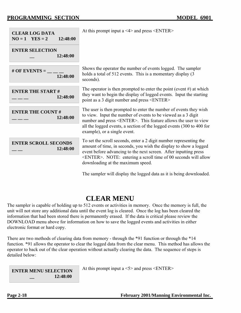
PROGRAMMING SECTION MODEL 6901
Page 2-18 February 2001/Manning Environmental Inc.
CLEAR LOG DATANO = 1 YES = 2 12:48:00
ENTER SELECTION __ 12:48:00
At this prompt input a <4> and press <ENTER>
# OF EVENTS = __ __ __ 12:48:00
Shows the operator the number of events logged. The samplerholds a total of 512 events. This is a momentary display (3seconds).
ENTER THE START #__ __ __ 12:48:00
The operator is then prompted to enter the point (event #) at whichthey want to begin the display of logged events. Input the startingpoint as a 3 digit number and press <ENTER>
ENTER THE COUNT #__ __ __ 12:48:00
The user is then prompted to enter the number of events they wishto view. Input the number of events to be viewed as a 3 digitnumber and press <ENTER>. This feature allows the user to viewall the logged events, a section of the logged events (300 to 400 forexample), or a single event.
ENTER SCROLL SECONDS__ __ 12:48:00
To set the scroll seconds, enter a 2 digit number representing theamount of time, in seconds, you wish the display to show a loggedevent before advancing to the next screen. After inputting press<ENTER>. NOTE: entering a scroll time of 00 seconds will allowdownloading at the maximum speed.
The sampler will display the logged data as it is being downloaded.
CLEAR MENUThe sampler is capable of holding up to 512 events or activities in memory. Once the memory is full, theunit will not store any additional data until the event log is cleared. Once the log has been cleared theinformation that had been stored there is permanently erased. If the data is critical please review theDOWNLOAD menu above for information on how to save the logged events and activities in eitherelectronic format or hard copy.
There are two methods of clearing data from memory - through the *91 function or through the *14function. *91 allows the operator to clear the logged data from the clear menu. This method has allows theoperator to back out of the clear operation without actually clearing the data. The sequence of steps isdetailed below:
ENTER MENU SELECTION __ 12:48:00
At this prompt input a <5> and press <ENTER>

MODEL 6901 PROGRAMMING SECTION
February 2001/Manning Environmental Inc. Page 2-19
CLEAR LOG DATANO = 1 YES = 2 12:48:00
This display is shown momentarily to orient the user to theupcoming menu selection.
CLEAR?? NO = 1 YES = 2 12:48:00
Enter your selection at the prompt:1 This does not clear the data and will take you back to the
ENTER SELECTION prompt.
2 This will clear all data. If the data needs to be retained,make sure a backup exists. Once the data has been deletedit is unrecoverable. After the data is cleared, you will betaken back to the ENTER SELECTION prompt.
*14 CLEAR LOG DATA
* 14 Clear Log Data option allows the operator to clear the logged data without entering the *91 datalogging program. This selection does not give the user the opportunity to back-out of the clearing of thelog. This is an immediate and unalterable erasure. The *14 clear data unlike the *91 clear data is accessiblefrom the SAMPLER READY prompt
SAMPLER READY12:48 12:48:00
This display shows the sampler is ready to program. It displays thecurrent time. From here the user can enter any TIME, FLOW, or * Mode. Press the * key to access the * Mode.
ENTER * MODE? __ __ 12:48:00
Prompts the user to enter either a program or the configurationfunction. Press 14 and <ENTER> to erase the logged data.
CLEARING LOG DATA
The menu shows the log being cleared. The log is now clear. Thedata that was contained within the log is now erased and isunrecoverable.
SAMPLER READY12:48 12:48:00
The unit returns to the SAMPLER READY prompt awaitingfurther action.
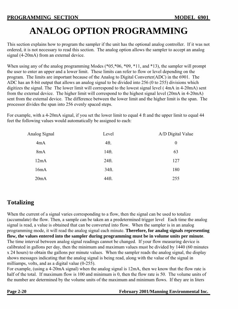
PROGRAMMING SECTION MODEL 6901
Page 2-20 February 2001/Manning Environmental Inc.
ANALOG OPTION PROGRAMMINGThis section explains how to program the sampler if the unit has the optional analog controller. If it was notordered, it is not necessary to read this section. The analog option allows the sampler to accept an analogsignal (4-20mA) from an external device.
When using any of the analog programming Modes (*05,*06, *09, *11, and *13), the sampler will promptthe user to enter an upper and a lower limit. These limits can refer to flow or level depending on theprogram. The limits are important because of the Analog to Digital Converter(ADC) in the 6901. TheADC has an 8-bit output that allows an analog signal to be divided into 256 (0 to 255) divisions whichdigitizes the signal. The The lower limit will correspond to the lowest signal level ( 4mA in 4-20mA) sentfrom the external device. The higher limit will correspond to the highest signal level (20mA in 4-20mA)sent from the external device. The difference between the lower limit and the higher limit is the span. Theprocessor divides the span into 256 evenly spaced steps.
For example, with a 4-20mA signal, if you set the lower limit to equal 4 ft and the upper limit to equal 44feet the following values would automatically be assigned to each:
Analog Signal Level A/D Digital Value
4mA 4ft. 0
8mA 14ft. 63
12mA 24ft. 127
16mA 34ft. 180
20mA 44ft. 255
Totalizing
When the current of a signal varies corresponding to a flow, then the signal can be used to totalize(accumulate) the flow. Then, a sample can be taken an a predetermined trigger level Each time the analogsignal is read, a value is obtained that can be converted into flow. When the sampler is in an analogprogramming mode, it will read the analog signal each minute. Therefore, for analog signals representingflow, the values entered into the sampler during programming must be in volume units per minute. The time interval between analog signal readings cannot be changed. If your flow measuring device iscalibrated in gallons per day, then the minimum and maximum values must be divided by 1440 (60 minutesx 24 hours) to obtain the gallons per minute values. When the sampler reads the analog signal, the displayshows messages indicating that the analog signal is being read, along with the value of the signal inmilliamps, volts, and as a digital value (0-255). For example, (using a 4-20mA signal) when the analog signal is 12mA, then we know that the flow rate ishalf of the total. If maximum flow is 100 and minimum is 0, then the flow rate is 50. The volume units ofthe number are determined by the volume units of the maximum and minimum flows. If they are in liters

MODEL 6901 PROGRAMMING SECTION
February 2001/Manning Environmental Inc. Page 2-21
then the flow is in liters, if they are in gallons then the flow is in gallons.
*08 Analog Display Routine
The analog display routine allows the operator to display the analog signal received from an external meter(level, flow pH, etc.). This routine can be used while the sampler is being installed, connected to a flowmeter, or to check the calibration of the sampler’s analog to digital converter.
The program is started by entering <*08> at the “SAMPLER READY” prompt. The analog value will be displayed in three formats: 1) As a digital value (0 to 255); 2) As a DC voltage (1 to 5 VDC); and 3) inmilliamps (4.0 to 20.0 mA). The program will continue to loop until reset by the operator pressing andholding the <RESET> until the sampler resets. The analog input signal can be varied while the program isrunning and the display will change accordingly.
The sampler’s analog routine can be calibrated by inputting a known milliamp signal or attaching a variablevoltage source across the analog input terminals.
ANALOG VALUES TABLETABLE A1
mA DC VOLTS DIGITALVALUE
4.0 1.00 0005.0 1.25 0156.0 1.50 0317.0 1.75 0478.0 2.00 0639.0 2.25 07910 2.50 09511 2.75 11112 3.00 12713 3.25 14314 3.50 15915 3.75 17516 4.00 19117 4.25 20718 4.50 22319 4.75 23920 5.00 255
Table A1 is a conversion table for the analog values. For example, if a voltage of 3.00 volts is placed acrossthe analog input terminals the sampler should display 12 mA, 3.00 VDC and a digital value of 127. Theanalog input circuit is designed with a precision 250 ohm resistor across the input terminals. When an mAanalog signal is input the current flows through the 250 ohm resistor generating a voltage drop proportional

PROGRAMMING SECTION MODEL 6901
Page 2-22 February 2001/Manning Environmental Inc.
to the current flow. At 12 mA the voltage drop is .012x250 = 3.00 volts. The three volts is converted into adigital value 127. When a three volt signal is placed across the analog input terminals it generates a currentflow according to ohms law of I = 3/250 = .012 mA.
Current loop calibrators are a common method of testing and calibrating 4-20mA current loops. It is alsopossible to use a known voltage source such as small batteries and a voltmeter for testing and calibrationpurposed.
A 4-20 mA source can be calibrated by placing a 250 ohm resistor in the loop and measuring the voltagedrop across the resistor with a voltmeter. Table A1 can be used to interpolate the corresponding mA signalor Ohms law (V/R = 1) can be used to calculate the mA signal. If the voltage is 4.25, then the mA signal is4.25/250 = .017 amps or 17 mA.

MODEL 6901 PROGRAMMING SECTION
February 2001/Manning Environmental Inc. Page 2-23
ADD-ON PROGRAMMING FUNCTIONS
Multiple Bottles per Sampling Event Multiple Bottles per Sampling Event is not a stand alone function but works in conjunction with TIME,FLOW and certain * Modes (*02, *04, *05, *06, *09) to expand the capabilities of the sampler. This optionplaces 1 sample in from 2-24 bottles in rapid succession during 1 sampling event (such as a contact closureor a time interval). To use Multiple Bottle per Sampling Event, the user selects the mode of choice - aTIME, FLOW, or * Mode. After entering the required information, the PUSH START/OPTIONS promptwill appear on the display. At this cue press <MULTI BOTTLE> and enter the number of bottles intowhich 1 sample should be placed, in rapid succession. For example, Multiple Bottles per Sampling Eventwould be used if a sample is to be taken every 100,000 gallons, and 1 sample is to be placed in 5 differentbottles each time there is a contact closure. The unit would start the sampling sequence after it had receiveda contact closure. It would draw and place 1 sample in the first bottle, immediately move to the second,draw and place 1 sample in that bottle, immediately move to the third, draw and place 1 sample in thatbottle and so on until it had deposited 1 sample in the specified number of bottles (in this example 5).
Display on LCD Explanation
SAMPLER READY12:48 12:48:00
This display indicates the sampler is ready to program. MultipleBottles per Sampling Event is not a stand alone program. It worksin conjunction with FLOW, TIME, and certain * Modes. In thisexample <FLOW> was pushed as the mode of choice.
PUSH START/OPTIONS 12:48:00
At this prompt the user selects Multiple Bottles per SamplingEvent, by pressing <MULTI BOTTLE>.
BOTTLES PER SAMPLE? __ __ 12:48:00
Input the number of bottles into which 1 sample will be placed inrapid succession during a sampling event and press <ENTER>.
PUSH START/OPTIONS 12:48:00
At this point, simply press <START>. NOTE: Multiple Bottles perSampling Event and Multiple Samples per Bottle cannot beselected simultaneously. They are mutually exclusive options.
FLOW MODE0000 B F 12:48:00
The unit is now waiting for a contact closure to initiate the samplesequence.

PROGRAMMING SECTION MODEL 6901
Page 2-24 February 2001/Manning Environmental Inc.
Multiple Samples per Bottle
Multiple Samples per Bottle is not a stand alone function but works in conjunction with other TIME, FLOWand certain * Modes (*02, *04, *05, *06, *09) to expand the capabilities of the sampler. The sampler placesfrom 2 to 99 samples in each bottle. In order to use Multiple Samples per Bottle, the user selects the modeof choice - a TIME, FLOW, or * Mode. After entering the required information, the PUSH START/OPTIONS prompt will appear on the display. At this cue press <MULTI SAMPLE> and enter the numberof samples per bottle. For example, if Flow Mode were being used and Multiple Samples Per Bottle is set at5, each time an event occurred, such as a contact closure or the end of a time interval, the sampler wouldplace a sample in a bottle. When the next event occurs, the sampler would place another sample in theSAME bottle, until 5 samples had been placed in that bottle. It would then advance the spout to the nextbottle in sequence. The sampler would then repeat the process above for the current bottle. This wouldcontinue until the total number of bottles the unit is configured for (set in *99) have received their allocationof samples. Although primarily designed for multi-bottle samplers, Multiple Samples per Bottle can also be used to set alimit on the number of samples that a single bottle sampler takes. In this instance, the sampler depositssamples into the container until the number of samples entered after pressing <MULTI SAMPLE> has beenreached. Note: A bottle full condition takes precedence over this.
Display on LCD Explanation
SAMPLER READY12:48 12:48:00
This display indicates the sampler is ready to program. MultipleSamples per Bottle is not a stand alone program. It works inconjunction with FLOW, TIME and certain * Modes. In thisexample <FLOW> was pushed as the mode of choice.
PUSH START/OPTIONS 12:48:00
At this prompt the user selects Multiple Samples per Bottle, bypressing <MULTI SAMPLE>.
SAMPLES PER BOTTLE? __ __ 12:48:00
Input the number of bottles into which 1 sample will be placedduring a sampling event and press <ENTER>.
PUSH START/OPTIONS 12:48:00
At this point, simply press <START>. NOTE: Multiple Bottles perSampling Event and Multiple Samples per Bottle cannot beselected simultaneously. They are mutually exclusive options.
FLOW MODE0000 S F 12:48:00
The unit is now waiting for a contact closure to initiate the samplesequence.

MODEL 6901 PROGRAMMING SECTION
February 2001/Manning Environmental Inc. Page 2-25
Delay Start - Time
Delay Start - Time works in conjunction with TIME and certain * Modes to expand the capabilities of thesampler. It is not a stand alone program and cannot be used with * Start, FLOW MODES, *01, *05, *06,*09, *11, *12, or *13. Delay Start - Time works by allowing the user to add a period of time to thebeginning of a TIME or * Mode to delay the start of the program. This time period must elapse before theprogram can begin to operate. NOTE: Some programs already have a Delay Start - Time in the programnegating the user's ability to add an additional Delay Start - Time. The user selects the mode of choice andenters the required information. The PUSH START/OPTIONS prompt will then appear on the display. Atthis cue press <DELAY START> and enter the amount of time (in HH:MM format) the sampler is to waitbefore beginning the program. Once the Delay Start has elapsed, the program will start. For example, if thesampler were programmed with a 9.5 hour Delay Start - Time and a 1.5 hour Time Interval, the samplerwould wait for 11 hours until the first sample is taken, (9.5 hours of Delay Start - Time and 1.5 hours for theTime Interval). The sampler would then take a sample every 1.5 hours until all of the bottles (set in *99)each have a sample placed in them or a bottle full condition occurs.
Display on LCD Explanation
SAMPLER READY12:48 12:48:00
This display indicates the sampler is ready to program. Delay Start- Time is not a stand alone program. It works in conjunction withTIME, and certain * Modes. In this example <TIME> was pushedas the mode of choice.
ENTER INTERVAL TIME_ _:_ _ 12:48:00
Enter the time interval as a 4-digit number (HH:MM format) andthen press <ENTER>.
PUSH START/OPTIONS 12:48:00
The program can then be started by pressing <START> or otherfunctions can be added on such as Delay Start - Time. In thisexample <DELAY START> was pressed.
ENTER DELAY START_ _:_ _ 12:48:00
This display prompts the user to enter a Delay Start time (inHH:MM format). This is the amount of time the sampler is to waitbefore starting the regular program (in this case TIME mode).
PUSH START/OPTIONS 12:48:00
The sampler is now ready to begin operation. Press <START> tobegin the Delay Start countdown, or add other options such asMultiple Samples per Bottle or Multiple Bottles per SamplingEvent.
DELAY START TIME_ _:_ _ 12:48:00
This display shows the time remaining on the Delay Start.
TIME TO NEXT SAMPLE_ _:_ _ D T 12:48:00
Once the Delay Start has counted down to zero, the Interval Timeentered earlier will begin counting down. This display shows thetime left to take a sample. As mentioned above, Delay Start - Timeworks with TIME, and certain * Modes.

PROGRAMMING SECTION MODEL 6901
Page 2-26 February 2001/Manning Environmental Inc.
*16 Midnight Switch(Bottle Advance)
This program allows the operator to toggle the midnight switch on(active) or off(inactive) on samplersconfigured for multi-bottle operation. With the midnight switch active(on), the sampler will advance thespout to the next bottle on the first sample initiation after midnight. For example, if your sampler isprogrammed to take samples based on flow (contact closure) input, with multiple samples in each bottle, thefirst contact closure that the sampler received after midnight will cause the spout to advance to the nextbottle, even if the programmed number of samples per bottle had not been met. This allows separation ofsample bottles by day of week. *16 works in a toggle mode, that is if the midnight switch is off entering *16 will toggle in on. If themidnight switch is on, entering *16 will toggle it off. *16 Mode is not available if the sampler is configured(*99 Mode) as a single-bottle unit.
SAMPLER READY12:48 12:48:00
This display indicates the sampler is ready to program. Delay Start- Time is not a stand alone program. It works in conjunction withTIME, and certain * Modes. In this example <TIME> was pushedas the mode of choice.
ENTER * MODE __ __ 12:48:00
The sampler is now prompting for a star mode to be input. Enterthe numbers which represent the star mode of choice, in this case16, and then press <ENTER>.
MIDNIGHT SWITCH ON 12:48:00
Momentarily displays that midnight switch is on.
SAMPLER READY12:48M 12:48:00
The display now returns to SAMPLER READY. In position 6 ofthe second line of the display a “M” is showing. This indicates tothe operator that the midnight switch is active. The midnightswitch remains active until the operator enters *16 Mode again totoggle it off. Resetting the sampler by pressing <RESET> twicewill not turn the midnight switch off.

MODEL 6901 PROGRAMMING SECTION
February 2001/Manning Environmental Inc. Page 2-27
GENERAL PROGRAMS
Time Mode - * Start
* START is a unique programming mode. It is unlike any other mode in that it automatically programs theunit to take a sample every hour. Simply press the * key and then <START>. As soon as <START> ispressed, the sampler begins counting down 1 hour. At the end of that hour the sample sequence will beinitiated. The sampler will advance the spout, draw 1 sample, and place it in a bottle. The time interval willreset as soon as the sample cycle starts. At the end of the second hour the spout will advance and anothersample will be taken and deposited. This will continue until the total number of bottles the unit isconfigured for (set in *99) each have 1 sample placed in them or a bottle full condition occurs. Thesequence will then be finished and the unit will stop operation waiting for the same or a new program to beentered. For example, if the sampler was configured for 24 bottles, the sampler would place 1 sample ineach bottle, over a 24 hour period for a total of 24 samples, and then stop operation.
Display on LCD Explanation
SAMPLER READY10:04 10:04:00
This display indicates the sampler is ready to program and displaysthe current time. Press the * key to begin programming.
ENTER * MODE __ __ 10:04:00
At the ENTER * MODE prompt, press <START> to begin the *Start Mode.
TIME TO NEXT SAMPLE 01:00 T 10:04:00
The sampler is automatically programmed and the display willshow the time (in HH:MM format) until the next sample.

PROGRAMMING SECTION MODEL 6901
Page 2-28 February 2001/Manning Environmental Inc.
Time Mode - Single Time Interval
This mode is similar to * START except the user sets the Time Interval instead of having it automaticallyset to 1 hour. The user enters a time in HH:MM format from 1 minute to 99 hours and 59 minutes. Thistime interval is used to initiate each sampling sequence in this program until the sampler ends its cycleand/or is re-programmed. After the time interval is entered and the program has been initiated by pressing<START>, the sampler will begin counting down the time interval. When the interval has elapsed, the unitwill advance the spout, draw 1 sample, and place it in a bottle. The timer will reset as soon as the samplecycle starts and will immediately begin counting down the same time interval again. After the interval haselapsed again, the spout will advance and another sample will be taken and deposited. This will continueuntil the total number of bottles the unit is configured for (set in *99) each have 1 sample placed in them ora bottle full condition occurs. For example, if the time interval is set for 1 hour 30 minutes, the samplerwould count down 1 hour and 30 minutes, advance the spout, take the first sample, and reset the timer. After another 1 hour and 30 minutes the spout would advance to bottle 2, the sampler would take a sampleand reset the timer, etc.
Display on LCD Explanation
SAMPLER READY10:04 10:04:00
This display indicates the sampler is ready to program and displaysthe current time. Press <TIME> to begin programming.
ENTER INTERVAL TIME__ __:__ __ 10:04:00
Enter the time interval as a 4-digit number (HH:MM format) andthen press <ENTER>.
PUSH START/OPTIONS 10:04:00
The program can then be started by pressing <START> or otherfunctions can be added. In this example, <START> is pressed.
TIME TO NEXT SAMPLE__ __:__ __ T 10:04:00
The display will show the time until the next sample.

MODEL 6901 PROGRAMMING SECTION
February 2001/Manning Environmental Inc. Page 2-29
*15 Time Mode - Active Sampling Period
This mode is similar to TIME MODE - SINGLE TIME INTERVAL, but *15 allows the operator toprogram an active sampling period (range 00:00 to 99:59) that will terminate sampling when the activesampling period has expired. The active time period does not start counting down until a sampling programhas been entered and a sample triggered. If the operator enters a delay start time, then the active samplingperiod does not start until the delay start time has expired and a sample is attempted. When the active timeperiod expires (counts down to 00:00) the next time a sample is attempted a message will be displayedindicating the active time period has expired and no sample will be taken. An active time period expiredmessage will be logged.
If an end of sequence even (such as a bottle full) occurs before the active sampling period expires, then theactive time period will have no effect. If the active time period expires while a sample is in process thesample will be completed and no more samples will be taken. There are two methods to clear an active timeperiod. First, reset the sampler by pressing <RESET> twice. This will initiate a WARM START and setthe active time to 00:00. The second method is to enter the *15 mode and enter a time of 00:00. The “A”will disappear from the second line indicating no active time period is active. For sampling situations wherean active sampling period is not desired the operator will not enter an active time value.
The major use of the active sampling period will be in industrial monitoring situations where (as dictated bythe EPA) a valid sample period cannot be longer than 24 hours. For example, if an active sampling periodof 24 hours is required, then the operator would enter (starting from the SAMPLER READY display) the*15 mode. The software will prompt the operator to enter the active time period. The operator enters anACTIVE TIME PERIOD of 24:00. An “A” will appear in postion seven on the bottom of the two line bytwenty character display indicating an active time has been entered. The operator then enters a samplingprogram (time, flow, etc.).
Display on LCD Explanation
SAMPLER READY04/30 10:04:00
This display indicates the sampler is ready to program andalternately displays the current time and date. Press the * key tobegin programming.
ENTER PROGRAM #__ __ 10:04:00
The sampler is now prompting for a star mode to be input. Enterthe numbers which represent the star mode of choice, in thisexample 15, and press <ENTER>.
ENTER ACTIVE TIME __ __: __ __ 10:04:00
The sampler then asks for an active time period. This is theamount of time (1 min to 99 hours and 59 min) during which thesampler will place samples in the sample container(s). Enter thetime in HH:MM format and press <ENTER>.
SAMPLER READY 04:30:02 A 10:04:00
The sampler will return to the SAMPLER READY message anddisplay an “A” on the bottom line in character position sevenindicating an active time has been entered.

PROGRAMMING SECTION MODEL 6901
Page 2-30 February 2001/Manning Environmental Inc.
Once the active period has been setup using Program15, you can then enter a sampling program.

MODEL 6901 PROGRAMMING SECTION
February 2001/Manning Environmental Inc. Page 2-31
Flow Mode
Flow Modes differ from Time Modes in that instead of taking a sample after a time interval has elapsed, theunit will take samples after receipt of a contact closure from an external device. Whether those contactclosures are based off Flow, pH, Level, ORP, DO, etc. is transparent to the sampler. The unit simplyacknowledges a contact closure was received and that in turn triggers the sample collection process. InFLOW Mode the sampler does not control totalization, logging, or the meeting of certain parameters, etc. sothey must be done by the external device. Once the parameters have been met, a contact closure will beoutput to the sampler. Every time a contact closure is received, the sample collection process is initiated. The sampler will advance the spout, draw 1 sample and place it in a bottle. It will then wait for the nextcontact closure while displaying a running tally indicating the number of samples taken to that point. Thiswill continue until the total number of bottles the unit is configured for (set in *99) each have a sampleplaced in them or a bottle full condition occurs. If either of these two conditions occur, the sampler ends theprogram. NOTE: If the contact is closed at the end of the sample cycle, the controller will initiateanother sample cycle.
Display on LCD Explanation
SAMPLER READY10:04 10:04:00
This display indicates the sampler is ready to program and displaysthe current time. Press <FLOW> to begin programming.
PUSH START/OPTIONS 10:04:00
The program can then be started by pressing <START> or otherfunctions can be added. In this example, <START> was pressed.
FLOW MODE0000 F 10:04:00
The sampler is now waiting to accept contact closures to trigger thesample collection process.

PROGRAMMING SECTION MODEL 6901
Page 2-32 February 2001/Manning Environmental Inc.
Flow Mode - Pulse Accumulation
FLOW Mode - Pulse Accumulation operates the same as FLOW Mode except instead of taking a sampleafter every contact closure, a sample is taken after a set number of contact closures (from 2 - 9,999) havebeen accumulated. NOTE: This program uses <DELAY START> for setting the number of contactclosures to be accumulated. The display will show the number of contact closures the sampler isprogrammed to accumulate before taking a sample. Every time a contact closure is received, the samplerwill decrease the number needed on the display by one. This shows how many more contacts have yet to beaccumulated before a sample is taken. Once the set number of contact closures are received, the samplerwill advance the spout, draw 1 sample and then place it in a bottle. It will then wait for the nextaccumulation. This will continue until the total number of bottles the unit is configured for (set in *99) eachhave a sample placed in them or a bottle full condition occurs. If, either of these two conditions occur, thesampler ends the program. NOTE: If the contact is closed at the end of the sample cycle, the controllerwill count down one contact closure.
Display on LCD Explanation
SAMPLER READY10:04 10:04:00
This display indicates the sampler is ready to program and displaysthe current time. Press <FLOW> to begin programming.
PUSH START/OPTIONS 10:04:00
To set the number of contacts to be accumulated in FLOW Mode -Pulse Accumulation, press <DELAY START> and then the<START> button.
DELAY IN PULSES?_ _ _ _ 10:04:00
The user is now prompted to set the number of contact closures thesampler will accumulate before taking a sample (2 - 9,999). Untilit is changed or ends its cycle, it will always accumulate the samenumber of pulses before taking a sample.
PUSH START/OPTIONS 10:04:00
Unless add-on options to the program are desired, press <START>.
FLOW MODE_ _ _ _ P 10:04:00
This display shows the number of contact closures remainingbefore a sample will be taken. As contact closures are received thesampler counts down until it reaches 0. It will then take a sampleand reset to accumulate the entered number of contact closuresagain.
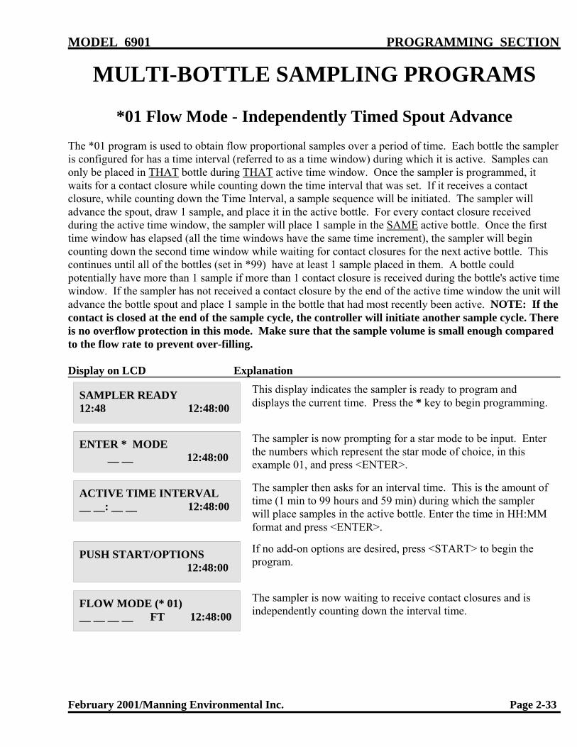
MODEL 6901 PROGRAMMING SECTION
February 2001/Manning Environmental Inc. Page 2-33
MULTI-BOTTLE SAMPLING PROGRAMS
*01 Flow Mode - Independently Timed Spout Advance
The *01 program is used to obtain flow proportional samples over a period of time. Each bottle the sampleris configured for has a time interval (referred to as a time window) during which it is active. Samples canonly be placed in THAT bottle during THAT active time window. Once the sampler is programmed, itwaits for a contact closure while counting down the time interval that was set. If it receives a contactclosure, while counting down the Time Interval, a sample sequence will be initiated. The sampler willadvance the spout, draw 1 sample, and place it in the active bottle. For every contact closure receivedduring the active time window, the sampler will place 1 sample in the SAME active bottle. Once the firsttime window has elapsed (all the time windows have the same time increment), the sampler will begincounting down the second time window while waiting for contact closures for the next active bottle. Thiscontinues until all of the bottles (set in *99) have at least 1 sample placed in them. A bottle couldpotentially have more than 1 sample if more than 1 contact closure is received during the bottle's active timewindow. If the sampler has not received a contact closure by the end of the active time window the unit willadvance the bottle spout and place 1 sample in the bottle that had most recently been active. NOTE: If thecontact is closed at the end of the sample cycle, the controller will initiate another sample cycle. Thereis no overflow protection in this mode. Make sure that the sample volume is small enough comparedto the flow rate to prevent over-filling.
Display on LCD Explanation
SAMPLER READY12:48 12:48:00
This display indicates the sampler is ready to program anddisplays the current time. Press the * key to begin programming.
ENTER * MODE __ __ 12:48:00
The sampler is now prompting for a star mode to be input. Enterthe numbers which represent the star mode of choice, in thisexample 01, and press <ENTER>.
ACTIVE TIME INTERVAL__ __: __ __ 12:48:00
The sampler then asks for an interval time. This is the amount oftime (1 min to 99 hours and 59 min) during which the samplerwill place samples in the active bottle. Enter the time in HH:MMformat and press <ENTER>.
PUSH START/OPTIONS 12:48:00
If no add-on options are desired, press <START> to begin theprogram.
FLOW MODE (* 01)__ __ __ __ FT 12:48:00
The sampler is now waiting to receive contact closures and isindependently counting down the interval time.

PROGRAMMING SECTION MODEL 6901
Page 2-34 February 2001/Manning Environmental Inc.
*02 Flow Mode - Time Interval Override
*02 operates much like basic FLOW mode except a time override is added. The override time ensures asample is collected, after a set amount of time has elapsed, if a contact closure has not been received. Oncethe program has been started the sampler will immediately begin counting down the override time. Thesampler is also concurrently waiting for contact closures. Every time a contact closure is detected thesampler will advance the spout, draw a sample, and then place it in a bottle. It will then wait for the nextcontact closure while displaying a running tally indicating the number of samples collected to that point. Ifthere have been no contact closures by the end of the override time the user specifies, the sampler willadvance the spout, draw a sample, and then place it in a bottle. The override timer will then reset andimmediately start counting down again while waiting for the next contact closure. This will continue untilthe total number of bottles the unit is configured for (set in *99) each have their set number of samplesplaced in them or a bottle full condition occurs. If either of these two conditions occur, the sampler ends theprogram. NOTE: If the contact is closed at the end of the sample cycle, the controller will initiateanother sample cycle.
Display on LCD Explanation
SAMPLER READY12:48 12:48:00
This display indicates the sampler is ready to program and displaysthe current time. Press the * key to begin programming.
ENTER * MODE __ __ 12:48:00
The sampler is now prompting for a star mode to be input. Enterthe numbers which represent the star mode of choice, in thisexample 02, and press <ENTER>.
TIME OVERRIDE?__ __ : __ __ 12:48:00
Input the maximum time the sampler will be allowed to wait toreceive a contact closure, understanding that if the unit has notreceived a closure in this time, it will automatically take a sample. Press <ENTER> after inputing.
PUSH START/OPTIONS 12:48:00
If no add-on options are desired, press <START> to begin theprogram.
FLOW MODE (* 02)__ __ __ __ FT 12:48:00
The sampler is now ready to receive contact closures and isindependently counting down the Time Override.

MODEL 6901 PROGRAMMING SECTION
February 2001/Manning Environmental Inc. Page 2-35
*03 Flow Mode - External Event
*03 is used for monitoring intermittent events by combining portions of Flow and Time modes. *03 differsfrom regular flow modes based on the way the sampler interacts with the contact closures it receives. Innormal flow mode the sampler receives a momentary closure from an external device, and this initiates asampling cycle. In *03 the sampler also initiates a sample cycle based off the initial contact closure itreceives. Once it has received that initial closure, the contact must remain closed for *03 to operate asintended. By the contact remaining closed, the time portion of the mode is brought into effect and the unitwill take samples based off a user set time interval. For example, assume the user has an external devicewith a relay that is normally open. The user sets a high and low trip point within the device. If an eventtakes place based on the high or low set point, the unit will send a closure to the sampler. This causes asampling cycle to take place. If the contact does not remain closed, the unit will act as if it wereprogrammed for regular flow mode, and simply take samples each time a contact closure is received. If therelay remains closed, however, the unit will then start to count down the user set time interval and once thatinterval has elapsed, take a sample. Each time the interval elapses, the unit will perform a samplingsequence. This will continue until the total number of bottles the unit is configured for (set in *99) eachhave their set number of samples placed in them or a bottle full condition occurs. If the contact opensbefore either of these two occurrences the sampler will suspend operation until it once again receives acontact closure that remains closed. After receiving another contact that remains closed the sampler willbegin where it left off from the last contact closure.
Display on LCD Explanation
SAMPLER READY12:48 12:48:00
This display indicates the sampler is ready to program and displaysthe current time. Press the * key to begin programming.
ENTER * MODE __ __ 12:48:00
The sampler is now prompting for a star mode to be input. Enterthe numbers which represent the star mode of choice, in thisexample 03, and press <ENTER>.
ENTER TIME INTERVAL__ __:__ __ 12:48:00
Input a time interval in HH:MM format.
PUSH START/OPTIONS 12:48:00
If no add-on options are desired, press <START> to begin theprogram. NOTE: DELAY START does not work with *03.
FLOW MODE (* 03)__ __ __ __ FT 12:48:00
The sampler is now ready to receive contact closures and isindependently counting down the Time Override.

PROGRAMMING SECTION MODEL 6901
Page 2-36 February 2001/Manning Environmental Inc.
*04 Time Mode - Multiple Intervals
The *04 mode allows programming of up to 12 DIFFERENT non-uniform time intervals (1 min to 99 hoursand 59 minutes). Non uniform time intervals refer to each interval being different from the previous ornext interval. Once an interval is entered, the user is given the option of repeating the interval or entering anew interval. To repeat the interval, press <ENTER> once for each time the user wants the same intervalrepeated. The display will show the COUNT increasing, indicating the same interval is being loggedmultiple times. An interval can be the same as a previous interval as long as there is a DIFFERENT intervalbetween them. For example if 01:00 was entered for the first interval, 02:00 for the second, and then 01:00was entered again, this would be counted as THREE different intervals. After the program is initiated, thesampler will begin counting down the first interval. Once that interval has elapsed, the unit will start thesample taking sequence and will immediately start counting down the next interval. The sampler will drawand place a sample in 1 bottle and then advance the spout. The sampler will repeat the operation each timean interval expires. The sampler will continue this pattern until all the intervals entered have expired, thetotal number of bottles the unit is configured for (set in *99) each have at least 1 sample placed in them, or abottle full condition occurs. Data entry can be ended at any time by pressing the * key.
Display on LCD Explanation
SAMPLER READY12:48 12:48:00
This display indicates the sampler is ready to program and displaysthe current time. Press the * key to begin programming.
ENTER * MODE __ __ 12:48:00
The sampler is now prompting for a star mode to be input. Enterthe numbers which represent the star mode of choice, in thisexample 04, and press <ENTER>.
ENTER FIRST INTERVAL__ __ :__ __ 12:48:00
The user is prompted to input the first time interval in HH:MMformat. Once the entry is complete press <ENTER>. The samplerconsiders this the FIRST time interval.
INTERVAL:1 COUNT: 1 01 :00 12:48:00
The display is now indicating it has recorded 1 interval (up to 12different ones can be entered) and the interval has not beenrepeated. In this example the user entered an interval of 1 Hour. The user must now input a new interval or repeat the currentinterval.
INTERVAL:2 COUNT: 1 02 :00 12:48:00
The user inputs a new interval (0200) representing 2 hours. Thedisplay indicates the new interval has been logged by showing a(2) after the interval.
INTERVAL:2 COUNT: 2 02 :00 12:48:00
The user decides to duplicate the last interval. Press <ENTER>once for each time the current interval should be repeated. THISDOES NOT COUNT AS A NEW INTERVAL as shown by the 2after the COUNT.
INTERVAL:2 COUNT: 3 02 :00 12:48:00
In this example, the user has pressed <ENTER> again to loganother interval of the same length. This is the third interval of 2hours.

MODEL 6901 PROGRAMMING SECTION
February 2001/Manning Environmental Inc. Page 2-37
INTERVAL:3 COUNT: 1 01 : 00 12:48:00
The user has now logged a third DIFFERENT interval. Eventhough this is the same as Interval 1, it is considered a differentinterval since it is not the same as the previous interval. Aninterval that has been entered before can be repeated as long asthere is a different interval between intervals of like time. If 12different intervals are logged the PUSH START/OPTIONSprompt will appear. Otherwise data entry can be terminated at anypoint by pressing the * key.
PUSH START/OPTIONS 12:48:00
If no add-on options are desired, press <START> to begin theprogram.
TIME TO NEXT SAMPLE01:00 FT 12:48:00
The sampler displays the first time interval to be counted down.

PROGRAMMING SECTION MODEL 6901
Page 2-38 February 2001/Manning Environmental Inc.
*07 Flow Mode - Time Interval Delay
*07 operates much like basic FLOW mode except a time interval delay is added after a contact closure hasbeen received. Just like in FLOW mode, the sampler waits for receipt of a contact closure. Once thatclosure has been taken, the unit immediately begins counting down a user set time interval delay. Once thedelay has counted down, the unit performs a sampling sequence. It will then wait for the next contactclosure while displaying a running tally indicating the number of samples collected to that point. Upon thenext closure the unit will once again count down the user set interval and then take a sample. This willcontinue until the total number of bottles the unit is configured for (set in *99) each have their set number ofsamples placed in them or a bottle full condition occurs. If either of these two conditions occur, the samplerends the program.
Display on LCD Explanation
SAMPLER READY12:48 12:48:00
This display indicates the sampler is ready to program and displaysthe current time. Press the * key to begin programming.
ENTER * MODE __ __ 12:48:00
The sampler is now prompting for a star mode to be input. Enterthe numbers which represent the star mode of choice, in thisexample 02, and press <ENTER>.
TIME DELAY?__ __ : __ __ 12:48:00
Input the time the sampler is to wait, after receipt of a contactclosure, to take a sample. After getting the signal the unit willcount down the interval and take a sample. Press <ENTER> afterinput.
PUSH START/OPTIONS 12:48:00
If no add-on options are desired, press <START> to begin theprogram.
DELAYED SAMPLE (*07)__ __ __ __ F 12:48:00
The sampler is now ready to receive contact closures.

MODEL 6901 PROGRAMMING SECTION
February 2001/Manning Environmental Inc. Page 2-39
ANALOG SAMPLING PROGRAMS
*05 Flow Mode - Totalizing Analog
The *05 mode works much like FLOW mode except instead of relying on a contact closure, the samplerintegrates and totalizes an analog signal (4-20mA) from an external device which represents flow rate. Formore details on how the analog controller works, refer to the analog programming section on page 2-8. Since the sampler does not ask for a definition of the volume unit of the flow rate, ANY can be used, i.e.cubic feet, liters or gallons. Once the unit is programmed, it begins reading the analog signal once perminute to internally totalize and keep track of the volume. When the totalized flow rate matches the SampleTrigger Volume entered by the user, the sample collection process is initiated. The unit will advance thespout, take a sample and deposit it in the first bottle. Every time the totalized volume matches the SampleTrigger Volume, the sampler will take a sample and deposit it, and then move to the next bottle in sequence. The sampler will continue this pattern of depositing a sample in each bottle, until the total number of bottlesthe unit is configured for (set in *99) each have a sample placed in them or a bottle full condition occurs.
NOTE: In order for the sampler to correctly scale the analog signal being output from the external device,the parameters (in this case maximum and minimum flow) set in the sampler and the external device mustbe the same. This is to ensure that if the external device is reading 100,000 gallons and outputting a 4mAsignal, the sampler will also know that 100,000 gallons is equal to 4mA. If the parameters do notcorrespond there is a risk that the sampler will potentially not scale the analog signal correctly and willsubsequently not take samples at the anticipated or correct instances.
Display on LCD Explanation
SAMPLER READY12:48 12:48:00
This display indicates the sampler is ready to program and displaysthe current time. Press the * key to begin programming.
ENTER * MODE __ __ 12:48:00
The sampler is now prompting for a star mode to be input. Enterthe numbers which represent the star mode of choice, in thisexample 05, and press <ENTER>.
MAXIMUM FLOW RATE?__ __ __ __ 12:48:00
Input the 4 most significant digits of the Maximum anticipatedflow rate. Since the unit of measurement is generic it can stand forany volume/minute. If the flow rate is 40, it could be entered as: 4000, 0400, or 0040. The decimal point is implied, in each case, sobe consistent with all entries.
MINIMUM FLOW RATE? __ __ __ __ 12:48:00
Enter the 4 most significant digits of the Minimum anticipated flowrate. The same criteria apply to this input as to Maximum FlowRate.

PROGRAMMING SECTION MODEL 6901
Page 2-40 February 2001/Manning Environmental Inc.
FLOW MULTIPLIER? __ __ __ __ 12:48:00
The Flow Multiplier is used to scale the Maximum & MinimumFlow Rates. If the Max flow rate is 40,000, enter it as 4000 (first 4significant digits). The user would then enter a Flow Multiplier of10 (4000 x 10 = 40,000) to have the unit scale the flow rate as40,000.
SAMPLE TRIGGER? __ __ __ __ 12:48:00
Enter the 4 most significant digits that tell the sampler at whataccumulation of totalized flow a sample should be taken. Remember the decimal point is implied and must be consistentwith previous entries. If the user wanted to take a sample at150,000 units, the entry would be 1500.
TRIGGER MULTIPLIER? __ __ __ __ 12:48:00
The Trigger Multiplier is used to increase, if necessary, the SampleTrigger. Using the example above, if 150,000 units is the Triggerpoint, the Trigger Multiplier would be 100 (1500 x 100 = 150,000).
PUSH START/OPTIONS 12:48:00
If no add-on options are desired, press <START> to begin theprogram.
FLOW MODE (*05)__ __ __ __ A 12:48:00
The sampler is now waiting to take samples.

MODEL 6901 PROGRAMMING SECTION
February 2001/Manning Environmental Inc. Page 2-41
*06 Analog Level Mode
The *06 mode expands the capability of the sampler by allowing it to collect samples based on changinglevel parameters. The sampler is used in conjunction with an external device which outputs an analogsignal ( 4-20mA, 0-20mA, 0-1V, or 1-5V DC) representing level (for more details on how the analogcontroller works, refer to the analog programming section on page 2-8). The sampler does not ask for adefinition of this level unit, so ANY can be used, i.e. feet, meters, or inches. Once the unit is programmedand started, the sampler integrates the analog signal once per minute to internally track the water level. When the source water level rises above or falls below a Sampling Level, the sample collection process isinitiated. The sampler will advance the spout, take a sample and deposit it in the first bottle. Every time aSample Level is exceeded or passed after that, the sampler will take a sample, deposit it, and then move tothe next bottle in sequence. The sampler will continue this pattern of depositing samples in each bottle untilthe total number of bottles the unit is configured for (set in *99) each have a sample placed in them or abottle full condition occurs.
To use the *06 mode, the following entries must be entered:
UPPER LEVEL LIMIT This is the highest anticipated level of the source liquid. It acts as a ceiling. Ifthe water ever rises above the Upper Level Limit, the sampler considers thelevel as temporarily fixed at the highest Sampling Level (once the level fallsbelow this point, normal program operation resumes). It is important to makesure the Upper Level Limit is high enough to prevent this from occurring.
LOWER LEVEL LIMIT This is the lowest anticipated level of the source liquid. It acts as a floor. If itis possible for the level to drop below the Lower Level Limit, and it does, thesampler considers the level as temporarily fixed at the Lower Level Limit(once the level rises above this point, normal program operation resumes). Itis important to make sure the Lower Level Limit is low enough to prevent thisfrom occurring.
SAMPLING LEVEL (1-32) These are the levels at which samples will be taken (up to 32 levels can beprogrammed). Enter the level as a 4-digit number. Remember the decimalpoint is implied, and must be consistent with previous ones. The unit ofmeasure is generic so it can be feet, meters, etc. The * key will end data entryat any time if all 32 levels are not going to be entered.
The difference (delta) between the Upper Level Limit and the Lower Level Limit is called the span (ordistance). In figure 2-2, the Upper Level Limit is 37 and the Lower Level Limit is 2.5, so the span is 34.5.The controller divides the span into 256 equal steps, with each step equal to 0.39% (1/256) of the total. Thesampler will always display the next acceptable level. A level that is greater can be entered or the user canaccept the displayed entry.
The lowest Sampling Level, must be greater than the Lower Level Limit and each successive level must begreater than the previous level. In figure 2-2, the Lower Level Limit is 2.5 and Sampling Level 1 is 4.0. The highest sampling level can be equal to the Upper Level Limit, although this is not necessary. If it isequal to the Upper Level Limit, it must be entered separately. In figure 2-2, the highest sampling level isequal to the Upper Level Limit so it is entered as Sampling Level 7. Press <START> to begin the program.

PROGRAMMING SECTION MODEL 6901
Page 2-42 February 2001/Manning Environmental Inc.
NOTE: In order for the sampler to correctly scale the analog signal being output from the external device,the parameters (in this case Upper Level Limit and Lower Level Limit) set in the sampler and the externaldevice must be the same. This is to ensure that if the external device is reading 10 feet and outputting a4mA signal, the sampler will also know that 10 feet is equal to 4mA. If the parameters do not correspond,there is a risk that the sampler will potentially not scale the analog signal correctly and will subsequentlynot take samples at the anticipated or correct instances.
The Dots Represent Sample Events.
Figure 2-2 The Totalizing Analog Level Mode.
Display on LCD Explanation
SAMPLER READY12:48 12:48:00
This display indicates the sampler is ready to program and displaysthe current time. Press the * key to begin programming.
ENTER * MODE __ __ 12:48:00
The sampler is now prompting for a star mode to be input. Enterthe numbers which represent the star mode of choice, in thisexample 06, and press <ENTER>.
UPPER LEVEL LIMIT?__ __ __ __ 12:48:00
Enter the Upper Level Limit as a 4-digit number. Remember thedecimal is implied in this program and the unit of measure isgeneric, so if the user wants 10 feet/meters/inches/millimeters, itcould be entered as 0010, 0100, or 1000. Make sure to beCONSISTENT in entries throughout the program.
LOWER LEVEL LIMIT?__ __ __ __ 12:48:00
Enter the Lower Level Limit as a 4-digit number. Remember to beconsistent with the implied decimal from previous entries.
SAMPLING LEVEL 1? __ __ __ __ 12:48:00
Enter the first level as a 4-digit number remembering to put in theimplied decimal point. Sampling Level 1 must be greater than theLower Level Limit.

MODEL 6901 PROGRAMMING SECTION
February 2001/Manning Environmental Inc. Page 2-43
SAMPLING LEVEL 2? __ __ __ __ 12:48:00
Continue to enter 4-digit numbers for Sampling Levels (up to 32levels) remembering that each subsequent level must be greaterthan the proceeding one and that the decimal point is implied andmust be consistent with previous entries. The user can end dataentry at any point by pressing the * key.
PUSH START/OPTIONS 12:48:00
If no add-on options are desired, press <START> to begin theprogram.
FLOW MODE (* 06)__ __ __ __ A 12:48:00
The sampler will immediately begin reading the analog signal.

PROGRAMMING SECTION MODEL 6901
Page 2-44 February 2001/Manning Environmental Inc.
*09 Hydrologic Level Event Mode(Storm Water Sampling)
The *09 mode is used primarily for Storm Water Sampling, although it can be used to sample in anysituation where there are rising and falling levels. The sampler is used in conjunction with an externaldevice which outputs an analog signal (4-20mA, 0-20mA, 0-1V, or 1-5V DC) representing level (for moredetails on how the analog controller works, refer to the analog programming section on page 2-8). Thesampler does not ask for a definition of this level so ANY can be used, i.e. feet, meters, or inches. After theunit has been programmed and started, it reads the analog signal once per minute to internally track thewater level. Sampling does not begin until the source water level reaches Sampling Level 1. Once this hasoccurred, a sample is taken and the Time Override for Sampling Level 1 begins counting down. AfterSampling Level 1 is reached, *09 Mode has 3 ways to trigger a sample:
1) When the analog signal corresponds to a Sampling Level. 2) The rise or fall of the water level by a user set amount (Rising or Falling Delta).3) When the Time Override has elapsed if there has not been a large enough increase or decrease in water
level or another Sampling Level has not been reached.
If any of these occur, the sampler will advance the spout, take a sample and deposit it in the first bottle. Thesampler will continue this pattern of depositing samples in each bottle, until the total number of bottles theunit is configured for (set in *99) each have a sample placed in them or a bottle full condition occurs. Ifeither of the first two triggering conditions is met (the analog signal corresponding to a Sampling Level or aRising or Falling Delta), the Time Override is reset, and begins counting down again. A different TimeOverride can be set for each level entered. Each Time Override is only active in that portion or range of thetotal span that corresponds to its Sampling Level. Time Override 4 is active from the start of SamplingLevel 4 to the beginning of Sampling Level 5.
The following entries are required. See figure 2-3 for an example.
Upper Level Limit Maximum Analog Level (hydrologic high point) 100% of span.
Lower Level Limit Minimum Analog level (hydrologic low point). 0% of span. The differencebetween the Upper Level Limit and the Lower Level Limit is the span.
Rising (positive)Delta
Rising change in water level, resulting in a sample. NOTE: The user can enteronly 1 Rising Delta for the duration of the program.
Falling (negative) Delta
Falling change in water level, resulting in a sample. NOTE: The user can enteronly 1 Falling Delta for the duration of the program.
Sampling Level 1 Water level at which the first sample will be taken, and which is associated withTime Override 1.
Time Override 1 Time Override to the next sample in the range. Causes a sample to be taken if theRising or Falling Delta, or Sampling Level 2 has not been met within the overridetime. It will reset after a sample is taken.
Sampling Level 2-6 Subsequent higher levels at which samples will be taken.
Time Override 2-6 Subsequent Time Overrides that correspond to the equivalent Sampling Level.

MODEL 6901 PROGRAMMING SECTION
February 2001/Manning Environmental Inc. Page 2-45
The difference (delta) between the Upper Level Limit and the Lower Level Limit is called the span (ordistance). In figure 2-3, the Upper Level Limit is 65 and the Lower Level Limit is 4, so the span is 61. Thecontroller divides the span into 256 equal steps, with each step equal to .39% (1/256) of the total. If a levelwhich is not a multiple of 1/256 is entered, the controller will indicate an acceptable entry. Up to 6 levelscan be entered, however data entry can be stopped at any time by pressing the * key. After the * key ispressed, the LCD will prompt the user to either start the Program or add-on other options.
NOTE: In order for the sampler to correctly scale the analog signal being output from the external device,the parameters (in this case Upper Level Limit and Lower Level Limit) set in the sampler and the externaldevice must be the same. This is to ensure that if the external device is reading 10 feet and outputting a4mA signal, the sampler will also know that 10 feet is equal to 4mA. If the parameters do not correspond,there is a risk that the sampler will potentially not scale the analog signal correctly and will subsequentlynot take samples at the anticipated or correct instances.
Figure 2-3 The *09 Storm Water Sampling Mode
Display on LCD Explanation

PROGRAMMING SECTION MODEL 6901
Page 2-46 February 2001/Manning Environmental Inc.
SAMPLER READY12:48 12:48:00
This display indicates the sampler is ready to program and displaysthe current time. Press the * key to begin programming.
ENTER * MODE __ __ 12:48:00
The sampler is now prompting for a star mode to be input. Enterthe numbers which represent the star mode of choice, in thisexample 09, and press <ENTER>.
UPPER LEVEL LIMIT?__ __ __ __ 12:48:00
Enter the Upper Level Limit as a 4-digit number. Remember thedecimal is implied in this program and the unit of measure isgeneric, so if the entry were to be 10feet/meters/inches/millimeters, it could be entered as 0010, 0100,or 1000. Be CONSISTENT in all entries throughout the program.
LOWER LEVEL LIMIT?__ __ __ __ 12:48:00
Enter the Lower Level Limit as a 4-digit number. Remember to beconsistent with the implied decimal from previous entries.
RISING DELTA?__ __ __ __ 12:48:00
Enter a 4-digit number which represents the rising change in waterlevel that will trigger a sample to be taken. If the rise of the wateris equal to or greater than this number a sample will be taken.
FALLING DELTA?__ __ __ __ 12:48:00
Enter a 4-digit number which represents the falling change in waterlevel that will trigger a sample to be taken. If the fall of the wateris equal to or greater than this number a sample will be taken.
SAMPLING LEVEL 1?__ __ __ __ 12:48:00
Enter a 4-digit number that represents the lowest level at which asample is to be taken. Must be greater than the Lower Level Limit. Remember to be consistent with the implied decimal from previousentries.
TIME OVERRIDE 1?__ __ : __ __ 12:48:00
Enter a time in HH:MM format. This is the amount of time afterSampling Level 1 during which the sampler waits for an event(Rising or Falling Delta, Sampling Level 2 reached, etc.). If noevent occurs before the interval is done, a sample will be taken. Ifan event occurs, the Time Override will reset, or move to TimeOverride 2 if Sampling Level 2 has been reached.
SAMPLING LEVEL 2?__ __ __ __ 12:48:00
Enter a 4-digit number representing the next level at which asample should be taken, keeping consistent with the implieddecimal point in previous entries. A sample will be taken when thewater level rises to this point. Must be greater than SamplingLevel 1.
TIME OVERRIDE 2?__ __ __ __ 12:48:00
Enter a time in HH:MM format. Operates on the same principal asTime Override 1.

MODEL 6901 PROGRAMMING SECTION
February 2001/Manning Environmental Inc. Page 2-47
SAMPLING LEVEL 3?__ __ __ __ 12:48:00
Enter a 4-digit number. Operates the same as previous SamplingLevels.
TIME OVERRIDE 3?__ __ __ __ 12:48:00
Enter a time in HH:MM format. Operates on the same principal asTime Override 1. Continue to enter Levels and Times for up to 6levels. Data entry can be ended at any time by pressing the * key. The last level can be equal to the Upper Level Limit but it is notnecessary. If it is equal it must be entered separately.
PUSH START/OPTIONS 12:48:00
If no add-on options are desired, press <START> to begin theprogram.
FLOW MODE (*09)__ __ __ __ A 12:48:00
The sampler will immediately begin reading the analog signal.

PROGRAMMING SECTION MODEL 6901
Page 2-48 February 2001/Manning Environmental Inc.
MULTI-BOTTLE FLOW COMPOSITEPROGRAMS
*10 Flow Mode - Multiple Bottle Composite
The *10 mode augments basic flow mode by allowing Multiple Bottles per Sample and Multiple Samplesper Bottle to be used together. Normally they are mutually exclusive but *10 combines the two, using Flowwith Multiple Bottles per Sample as the base. It adds Multiple Samples per Bottle by letting the user placemultiple samples (1-99) in the same bottle creating a composite sample. NOTE: The number of samplesshould be equal to or less than the volume of the sample containers divided by the volume of the sample, toprevent over filling. The unit operates by accepting contact closures from an external device. Whetherthose contact closures are based off Flow, pH, Level, ORP, DO etc. is transparent to the sampler. The unitsimply acknowledges a contact closure was received and that in turn triggers the sample collection process. In *10 the sampler does not control totalization, logging, or the meeting of certain parameters, etc. so theymust be done by the external device. Once the parameters have been met, a contact closure will be output tothe sampler. Every time a contact closure is received, the sample collection process is initiated. The unitwill advance the spout, draw its samples and place them in the correct bottles. It will then wait for the nextcontact closure. This will continue until the total number of bottles the unit is configured for (set in *99)each have a sample placed in them or a bottle full condition occurs. If either of these two conditions aremet, the sampler ends the program.
For example, assume the sampler is configured for 24 bottles and Samples per Bottle is set to 3 (see step bystep programming below). The sampler, after receiving a contact closure, will in rapid succession place 1sample in each bottle it is configured for (set in *99). In this case, since the sampler is configured for 24bottles, a total of 24 samples would be deposited (one in each bottle). After depositing this set of samplesthe unit would pause awaiting the next contact closure to place the second set of samples in the bottles(there would be 48 total samples taken after the second contact closure - 2 in each bottle). After the thirdset, the sampler would end the sequence and wait for a new program (there would be 72 total samples taken- 3 in each bottle).
The override time causes the unit to take samples if the contact closure fails to occur. The override timestarts counting down immediately after pressing <START>. If a contact closure is received, the overridetime resets and immediately begins to count down again. NOTE: This means that the override time mustbe longer than the time it takes for the sampling sequence to complete. If it is not, the override time willelapse while the sampler is in the sequence causing the sampler to immediately start another sequence afterit finishes the previous one.
Display on LCD Explanation
SAMPLER READY12:48 12:48:00
This display indicates the sampler is ready to program and displaysthe current time. Press the * key to begin programming.

MODEL 6901 PROGRAMMING SECTION
February 2001/Manning Environmental Inc. Page 2-49
ENTER * MODE __ __ 12:48:00
The sampler is now prompting for a star mode to be input. Enterthe numbers which represent the star mode of choice, in thisexample 10, and press <ENTER>.
SAMPLES PER BOTTLE? __ __ 12:48:00
Enter the number of samples per bottle as a 2-digit number (1-99). Make sure the volume to be placed in the bottles is not greater thanthe actual volume of the bottles.
TIME OVERRIDE?__ __:__ __ 12:48:00
Enter in HH:MM format. Remember to allow enough time for thesampler to collect the required samples.
PUSH START/OPTIONS 12:48:00
If no add-on options are desired, press <START> to begin theprogram.
FLOW MODE (*10)__ __ __ __ B F 12:48:00
The sampler is now ready to receive contact closures and isindependently counting down the interval time.

PROGRAMMING SECTION MODEL 6901
Page 2-50 February 2001/Manning Environmental Inc.
*11 Flow Mode - Totalizing Analog Multiple Bottle Composite
This mode is a combination of *05 (the ability to process an analog signal), and *10 (the ability to useMultiple Bottles per Sample and Multiple Samples per Bottle together). *11 works by integrating andtotalizing an analog signal ( 4-20mA, 0-20mA, 0-1V, or 1-5V DC) from an external device that representsflow rate. For more details on how the analog controller works, refer to the analog programming section onpage 2-8. Since the sampler does not ask for a definition of the volume unit of the flow rate, ANY can beused, i.e. cubic feet, liters or gallons. Once the unit is programmed, it begins reading the analog signal onceper minute to internally totalize and keep track of the volume. When the totalized flow rate matches theSample Trigger Volume entered, the sample collection process is initiated. The unit will advance the spoutand in rapid succession draw and place its samples. The unit will then pause awaiting the next trigger. Every time the totalized volume matches the Sample Trigger Volume, the sampler will draw its samples,deposit them, and wait for another Sample Trigger. The sampler will continue this pattern until the totalnumber of bottles the unit is configured for (set in *99) each have a sample placed in them or a bottle fullcondition occurs.
For example, assume the sampler is configured for 24 bottles and Samples per Bottle is set to 3 (see step bystep programming below). The sampler, after receiving a contact closure, will in rapid succession place 1sample in each bottle it is configured for (set in *99). In this case, since the sampler is configured for 24bottles, a total of 24 samples would be deposited (one in each bottle). After depositing this set of samplesthe unit would pause awaiting the next contact closure to place the second set of samples in the bottles(there would be 48 total samples taken after the second contact closure - 2 in each bottle). After the thirdset, the sampler would end the sequence and wait for a new program (there would be 72 total samples taken- 3 in each bottle).
NOTE: In order for the sampler to correctly scale the analog signal being output from the external device,the parameters (in this case maximum and minimum flow) set in the sampler and the external device mustbe the same. This is to ensure that if the external device is reading 100,000 gallons and outputting a 4mAsignal, the sampler will also know that 100,000 gallons is equal to 4mA. If the parameters do notcorrespond, there is a risk that the sampler will potentially not scale the analog signal correctly and willsubsequently not take samples at the anticipated or correct instances.
The override time causes the unit to take samples if the Flow Trigger fails to occur. The override time startscounting down immediately after pressing <START>. If the Flow Trigger is received, the override timeresets and immediately begins to count down again. NOTE: This means that the override time must belonger than the time it takes for the sampling sequence to complete. If it is not, the override time will elapsewhile the sampler is in the sequence causing the sampler to immediately start another sequence after itfinishes the previous one. The time override fills bottles the same way as if a Flow Trigger were received. This will continue until the maximum number of samples (1-99) have been placed in the bottles (the numberof samples should be equal to or less than the volume of the sample containers divided by the volume of thesample, to prevent over filling).

MODEL 6901 PROGRAMMING SECTION
February 2001/Manning Environmental Inc. Page 2-51
Display on LCD Explanation
SAMPLER READY12:48 12:48:00
This display indicates the sampler is ready to program and displaysthe current time. Press the * key to begin programming.
ENTER * MODE __ __ 12:48:00
The sampler is now prompting for a star mode to be input. Enterthe numbers which represent the star mode of choice, in thisexample 11, and press <ENTER>.
MAXIMUM FLOW RATE?__ __ __ __ 12:48:00
Input the 4 most significant digits of the Maximum anticipatedflow rate. Since the unit of measurement is generic it can stand forany volume/minute. If the flow rate is 40, it could be entered as: 4000, 0400, or 0040. The decimal point is implied, in each case, sobe consistent with all entries.
MINIMUM FLOW RATE? __ __ __ __ 12:48:00
Enter the 4 most significant digits of the Minimum anticipated flowrate. The same criteria apply to this input as to Maximum FlowRate.
FLOW MULTIPLIER? __ __ __ __ 12:48:00
The Flow Multiplier is used to scale the Maximum & MinimumFlow Rates. If the Max flow rate is 40,000, enter it as 4000 (first 4significant digits). The user would then enter a Flow Multiplier of10 (4000 x 10 = 40,000) to have the unit scale the flow rate as40,000.
SAMPLE TRIGGER? __ __ __ __ 12:48:00
Enter the 4 most significant digits of totalized flow at which asample should be taken. Remember the decimal point is impliedand must be consistent with previous entries. If the user wanted totake a sample every 150,000 units, the entry would be 1500.
TRIGGER MULTIPLIER? __ __ __ __ 12:48:00
The Trigger Multiplier scales the Sample Trigger. Using theexample above, if 150,000 units is the Trigger point, the TriggerMultiplier would be 100 (1500 x 100 = 150,000).
SAMPLES PER BOTTLE? __ __ 12:48:00
Enter the number of samples per bottle as a 2-digit number (1-99). Make sure the volume to be placed in the bottles is not greater thanthe actual volume of the bottles.
TIME OVERRIDE? __ __ : __ __ 12:48:00
Enter in HH:MM format. Remember to allow enough time for thesampler to collect the required samples.
PUSH START/OPTIONS 12:48:00
If no add-on options are desired, press <START> to begin theprogram.
FLOW MODE (*11)__ __ __ __ A 12:48:00
The sampler will immediately begin reading the analog signal.

PROGRAMMING SECTION MODEL 6901
Page 2-52 February 2001/Manning Environmental Inc.
*12 Flow Mode - Multiple Bottle Composite with Bottle Groups
The *12 mode functions almost identically to *10 mode, however, in this mode, up to 24 separate bottlegroups can be created which accept composite samples. *12 is useful when it is not possible to collectsamples on a regular basis, such as on a weekend or at a remote site. In this mode the user selects thenumber of bottle groups, how long each group is active (receives samples), the maximum number ofsamples a group will take, and a time override. NOTE: The number of bottle groups is entered, not thenumber of bottles in a group. After pushing <START>, the sampler immediately begins counting down theDelay Start. Once the Delay Start has finished counting down the sampler will be ready to receive an event(contact closure or time override). The finish of the Delay Start will also start the time override countingdown. If the sampler receives an event, the unit will initiate the sampling sequence. There are severalsimultaneous actions.
1) The spout will advance to the first bottle in the active bottle group and begin the sampling process.
2) The active bottle group time will begin counting down. NOTE: Make sure the active time period allowsenough time to collect all the samples required. If the active time period elapses before the Samples perBottle has been satisfied, the unit will finish the sequence in progress and then move to the next bottle groupwithout completing the current bottle group.
3) The time override will reset and begin counting down again. The override time causes the unit to takesamples if a contact closure fails to occur. The override time starts counting down immediately afterpressing <START>. NOTE: The override time must be longer than the time it takes for the samplingsequence to complete. If it is not, the override time will elapse while the unit is in a sampling sequencecausing another sequence to begin immediately after finishing the previous one.
The first bottle group will be active and receive all samples for its active time period, up to the maximumnumber of samples. If the maximum is reached, the sampler will still wait out the rest of the active timebefore switching to the next bottle group. After the initiation of a sampling sequence, the sampler willadvance to the first bottle in the group. The unit will place 1 sample in this bottle, and then advance to thenext bottle in the group and deposit a sample. This will continue until all the bottles in the group have 1sample placed in them (see NOTE on #2 above). The sampler will then wait for another event (contactclosure or a time override elapse (see NOTE on #3 above)). When the event occurs the unit will placeanother sample in each bottle of the active group. This will continue, as events take place, until thespecified number of Samples per Bottle is reached and all Bottle Groups have been utilized. See page 2-36for a full explanation of how bottle groups are divided and what order the spout fills the bottles.
Display on LCD Explanation
SAMPLER READY12:48 12:48:00
This display indicates the sampler is ready to program and displaysthe current time. Press the * key to begin programming.
ENTER * MODE __ __ 12:48:00
The sampler is now prompting for a star mode to be input. Enterthe numbers which represent the star mode of choice, in thisexample 12, and press <ENTER>.

MODEL 6901 PROGRAMMING SECTION
February 2001/Manning Environmental Inc. Page 2-53
SAMPLES PER BOTTLE? __ __ 12:48:00
Enter number of samples per bottle as a 2-digit number (1-99). Make sure the volume to be placed in the bottles is not greater thanthe actual volume of the bottles.
TIME OVERRIDE? __ __ : __ __ 12:48:00
Enter in HH:MM format. Remember to allow enough time for thesampler to collect the required samples.
ENTER DELAY START__ __ : __ __ 12:48:00
This display prompts the user to enter a delay start time (HH:MMformat). This is the amount of time the sampler is to wait beforestarting.
ACTIVE PERIOD? __ __ : __ __ 12:48:00
Enter a time (HH:MM format). This is the time window in whichbottle groups are active. It applies to all bottle groups. Make sureit is long enough to allow the sampler to collect the number ofsamples required.
# OF BOTTLE GROUPS? __ __ 12:48:00
Enter a 2-digit number (must be an integer). This is the number ofbottle groups to be created from the number of bottles set in*99.The number of bottles will be divided by the number of bottlegroups to determine how many bottles are in a group.
PUSH START/OPTIONS 12:48:00
If no add-on options are desired, press <START> to begin theprogram.
DELAY START TIME__ __:__ __ 12:48:00
This display shows the time remaining on the Delay Start.
FLOW MODE (*12)__ __ __ __ SDFT 12:49:00
The sampler is now waiting to receive contact closures and isindependently counting down the interval time.

PROGRAMMING SECTION MODEL 6901
Page 2-54 February 2001/Manning Environmental Inc.
Figure 2-4 Bottle Group and Spout Advance

MODEL 6901 PROGRAMMING SECTION
February 2001/Manning Environmental Inc. Page 2-55
*13 Flow Mode - Totalizing Analog Multiple Bottle Composite with Bottle Groups
The *13 mode functions in the same way as the *12 mode, except it integrates and totalizes an analog signal( 4-20mA) from an external device that represents flow rate. Since the sampler does not ask for a definitionof the volume unit of the flow rate, ANY can be used, i.e. cubic feet, liters or gallons. For more details onhow the analog controller works, refer to the analog programming section on page 2-8. *13 is useful whenit is not possible to collect samples on a regular basis, such as on a weekend or at a remote site. In thismode the user selects the number of bottle groups, how long each group is active (receives samples), themaximum number of samples a group will take, and a time override. NOTE: The number of bottle groupsis entered, not the number of bottles in a group. After pushing <START>, the sampler immediately beginscounting down the Delay Start. Once the Delay Start has finished counting down, the sampler will beginreading the analog signal and be ready to act on an event (totalized volume or time override). The finish ofthe Delay Start will also start the time override counting down. If the sampler receives an event, the unitwill initiate the sampling sequence. There are several simultaneous actions:
1) The spout will advance to the first bottle in the active bottle group and begin the sampling process.
2) The active bottle group time will begin counting down. NOTE: Make sure the active time period allowsenough time to collect all the samples required. If the active time period elapses before the Samples perBottle has been satisfied, the unit will finish the sequence in progress and then move to the next bottle groupwithout completing the current bottle group.
3) The time override will reset and begin counting down again. The override time causes the unit to takesamples if the Flow Trigger fails to occur. The override time starts counting down immediately afterpressing <START>. NOTE: The override time must be longer than the time it takes for the samplingsequence to complete. If it is not, the override time will elapse while the unit is in a sampling sequencecausing another sequence to begin immediately after finishing the previous one.
The first bottle group will be active and receive all samples for its active time period, up to the maximumnumber of samples. If the maximum is reached, the sampler will still wait out the rest of the active timebefore switching to the next bottle group. After the initiation of a sampling sequence, the sampler willadvance to the first bottle in the group. The unit will place 1 sample in this bottle, and then advance to thenext bottle in the group and deposit a sample. This will continue until all the bottles in the group have 1sample placed in them (see NOTE on #2 above). The sampler will then wait for another event (totalizedvolume or time override (see NOTE on #3 above)). When the event occurs the unit will place anothersample in each bottle of the active group. This will continue, as events take place, until the specifiednumber of Samples per Bottle is reached and all Bottle Groups have been utilized. See page 2-36 for a fullexplanation of how bottle groups are divided and what order the spout fills the bottles.
NOTE: In order for the sampler to correctly scale the analog signal being output from the external device,the parameters (in this case maximum and minimum flow) set in the sampler and the external device mustbe the same. This is to ensure that if the external device is reading 100,000 gallons and outputting a 4mAsignal, the sampler will also know that 100,000 gallons is equal to 4mA. If the parameters do notcorrespond, there is a risk that the sampler will potentially not scale the analog signal correctly and willsubsequently not take samples at the anticipated or correct instances.

PROGRAMMING SECTION MODEL 6901
Page 2-56 February 2001/Manning Environmental Inc.
Display on LCD Explanation
SAMPLER READY12:48 12:48:00
This display indicates the sampler is ready to program and displaysthe current time. Press the * key to begin programming.
ENTER * MODE __ __ 12:48:00
The sampler is now prompting for a star mode to be input. Enterthe numbers which represent the star mode of choice, in thisexample 13, and press <ENTER>.
MAXIMUM FLOW RATE?__ __ __ __ 12:48:00
Input the 4 most significant digits of the Maximum anticipatedflow rate. Since the unit of measurement is generic it can stand forany volume/minute. If the flow rate is 40, it could be entered as: 4000, 0400, or 0040. The decimal point is implied, in each case, sobe consistent with all entries.
MINIMUM FLOW RATE? __ __ __ __ 12:48:00
Enter the 4 most significant digits of the Minimum anticipated flowrate. The same criteria apply to this input as to Maximum FlowRate.
FLOW MULTIPLIER? __ __ __ __ 12:48:00
The Flow Multiplier is used to scale the Maximum & MinimumFlow Rates. If the Max flow rate is 40,000, enter it as 4000 (first 4significant digits). The user would then enter a Flow Multiplier of10 (4000 x 10 = 40,000) to have the unit scale the flow rate as40,000.
SAMPLE TRIGGER? __ __ __ __ 12:48:00
Enter the 4 most significant digits of totalized flow at which asample should be taken. Remember the decimal point is impliedand must be consistent with previous entries. If the user wanted totake a sample every 150,000 units, the entry would be 1500.
TRIGGER MULTIPLIER? __ __ __ __ 12:48:00
The Trigger Multiplier scales the Sample Trigger. Using theexample above, if 150,000 units is the Trigger point, the TriggerMultiplier would be 100 (1500 x 100 = 150,000).
SAMPLES PER BOTTLE? __ __ __ __ 12:48:00
Enter the number of samples per bottle as a 2-digit number (1-99). Make sure the volume to be placed in the bottles is not greater thanthe actual volume of the bottles.
TIME OVERRIDE? __ __ : __ __ 12:48:00
Enter in HH:MM format. Remember to allow enough time for thesampler to collect the required samples.
ENTER DELAY START __ __ : __ __ 12:48:00
This display prompts the user to enter a delay start time (HH:MMformat). This is the amount of time the sampler is to wait beforestarting.

MODEL 6901 PROGRAMMING SECTION
February 2001/Manning Environmental Inc. Page 2-57
ACTIVE PERIOD? __ __ : __ __ 12:48:00
Enter a time (HH:MM format). This is the time window in whichbottle groups are active. It applies to all bottle groups. Make sureit is long enough to allow the sampler to collect the number ofsamples required.
# OF BOTTLE GROUPS? __ __ __ __ 12:48:00
Enter a 2-digit number (must be an integer). This is the number ofbottle groups to be created from the number of bottles set in *99.
PUSH START/OPTIONS 12:48:00
If no add-on options are desired, press <START> to begin theprogram.
DELAY START TIME__ __:__ __ 12:48:00
This display shows the time remaining on the Delay Start.
FLOW MODE (*13)__ __ __ __ SDAT 12:48:00
Once the Delay Start ends, the sampler will immediately beginreading the analog signal and begin counting down the TimeOverride.

PROGRAMMING SECTION MODEL 6901
Page 2-58 February 2001/Manning Environmental Inc.
THIS PAGE INTENTIONALLY LEFT BLANK

MODEL 6901 MAINTENANCE
February 2001/Manning Environmental Inc. Page 3-1
Maintenance and Troubleshooting
MAINTENANCEThe 6901 sampler requires only minimal maintenance to ensure proper and reliable operation.
CLEANING THE CONTROL PANEL
Use a mild cleaning solution and wipe with a soft, lint-free cloth.
CAUTION: Do not use harsh cleaners (detergents, solvents, etc.) which can damage the panel surface.Do not use abrasives which can scratch the panel and fog the window above the LCDdisplay.
CLEANING THE WETTED PARTS
Note: Solvents and solvent contaminated fluids must be disposed of according to approved procedures.
Manning Environmental Inc. recommends instituting a cleaning regime for the sampling equipment. Thefollowing are a few of the many reasons why a cleaning regime is important:
1. It validates that the samples taken will be as free as possible from constituents that arenot contained within the sample itself.
2. It contributes to ensuring that the statistical validity of the samples being examined willbe maximized by reducing systematic error, if the regime is followed very closely.
3. It contributes to the longevity of the sampling equipment.
4. It provides documentation for challenged results.
For a detailed description of a cleaning protocol refer to U.S. Environmental Protection AgencyPublications EPA-600/4-77-039 ("Sampling of Water and Wastewater" by Dr. Phillip E. Shelley), or consultwith the facility that will do the actual testing of the samples. They should be able to assist in setting acleaning regime that will help produce the most accurate results possible.
The following procedures are very general outlines of steps for cleaning certain parts of the sampler:
All toxic option (non-contaminating) wetted parts are autoclavable. Standard PVC wetted parts are not.
Intake Hose

MAINTENANCE MODEL 6901
Page 3-2 February 2001/Manning Environmental Inc.
There are two types of intake hose used with the sampler - PVC and Teflon®. PVC intake hose is used forgeneral purpose sampling (Non-Toxic) applications. Teflon® hose is used for priority pollutant sampling(Toxic) applications.
1. Remove the intake hose. Remove the strainer if necessary. Do not loosen thecompression rings!
2. Wash the intake hose and strainer using a cleaning solution appropriate for theapplication. The use of methylene chloride or other solvents may leave a residue whichcould contaminate future samples. Use a test tube brush to scrub the internal surfaces ofthe strainer, pull the brush through the hose with a wire to clean the internal surfaces ofthe hose.
3. Rinse the hose and strainer thoroughly in clean water and reassemble.
It may be easier and more convenient to simply use a new hose for each sample configuration. Thiseliminates cleaning and disposal of potentially hazardous regulated chemicals.
Measuring Chamber
Caution: Do not allow water to enter the differential pressure switch. Remove the pressure switch and itstubing before turning the chassis top or chamber top upside down. Unplug the tubing foradditional protection.
FAILURE TO KEEP THE PRESSURE SWITCH DRY WILL RESULT IN SWITCH FAILURE.
1. Pop the gray differential pressure switch and the attached tubing off the top of themeasuring chamber.
2. Remove the pressure and vacuum tubes from the red barbed fittings on the chamber top.
3. Disassembly of the red check valves is not necessary. If for some reason it becomesnecessary simply twist and pull to separate the two pieces. Do not disassemble the whitecheck valves inside.
4. Remove the two wingnuts from the top of the measuring chamber and lift the chambertop off the chamber.
5. Check the two o-rings, one at the top and one at the bottom of the measuring chamber,for gauges and imperfections, and replace the o-rings if necessary. (Do not uselubrication, as it may cause contamination.)
6. Wash the chamber with an appropriate cleaning solution. A test tube brush can be used toscrub the internal surfaces of the top fittings, slit tube and sleeve. Clean the chamberbase and pinch tube.
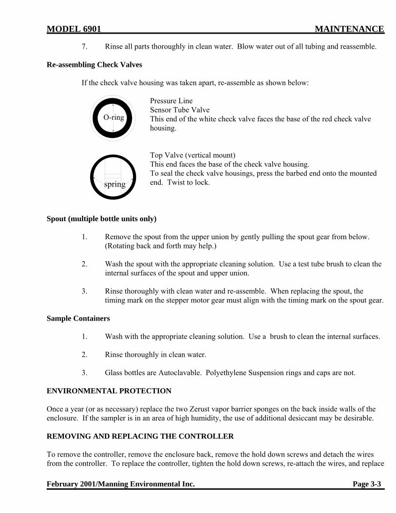
MODEL 6901 MAINTENANCE
February 2001/Manning Environmental Inc. Page 3-3
7. Rinse all parts thoroughly in clean water. Blow water out of all tubing and reassemble.
Re-assembling Check Valves
If the check valve housing was taken apart, re-assemble as shown below:
Pressure Line Sensor Tube ValveThis end of the white check valve faces the base of the red check valvehousing.
Top Valve (vertical mount)This end faces the base of the check valve housing.To seal the check valve housings, press the barbed end onto the mountedend. Twist to lock.
Spout (multiple bottle units only)
1. Remove the spout from the upper union by gently pulling the spout gear from below. (Rotating back and forth may help.)
2. Wash the spout with the appropriate cleaning solution. Use a test tube brush to clean theinternal surfaces of the spout and upper union.
3. Rinse thoroughly with clean water and re-assemble. When replacing the spout, thetiming mark on the stepper motor gear must align with the timing mark on the spout gear.
Sample Containers
1. Wash with the appropriate cleaning solution. Use a brush to clean the internal surfaces.
2. Rinse thoroughly in clean water.
3. Glass bottles are Autoclavable. Polyethylene Suspension rings and caps are not.
ENVIRONMENTAL PROTECTION
Once a year (or as necessary) replace the two Zerust vapor barrier sponges on the back inside walls of theenclosure. If the sampler is in an area of high humidity, the use of additional desiccant may be desirable.
REMOVING AND REPLACING THE CONTROLLER
To remove the controller, remove the enclosure back, remove the hold down screws and detach the wiresfrom the controller. To replace the controller, tighten the hold down screws, re-attach the wires, and replace

MAINTENANCE MODEL 6901
Page 3-4 February 2001/Manning Environmental Inc.
the enclosure back.
CHECKING THE PINCH VALVE
Frequently the pinch valve and the controller fail together. To determine whether one or both parts areneeded, follow these instructions.
1. Remove the chassis and locate the white pinch valve wires. Cut the wires 2" to 3" fromthe solenoid.
2. Press the TEST CYCLE key. During the part of the cycle when the pinch valve shouldhave been closing, check for 12VDC on the controller side of the wires.
3. Call the Manning Factory Service Department (800-863-9337) for assistance ifnecessary.
4. Use a butt-splice or twist connector to splice the wires.
Quick Check: A quick way to check for 12 VDC is to push a straight pin (or similar sharp conductor)through the insulation and into each wire. Be careful not to push the pins all the waythrough the wires. Attach the volt meter to the pins to check for a 12 VDC.
CHECKING THE DIFFERENTIAL PRESSURE SWITCH
Pressure switch failure can have serious consequences so it is important to replace the switch as soon aspossible when it begins to fail.
CAUTION: If the pressure switch fails completely, water can flow into the chamber and into thecompressor, resulting in more expensive repairs.
To check the pressure switch or fill sensor, follow these instructions.
1. Disconnect the wires leading to the pressure switch.
2. Press the TEST CYCLE key. During the draw cycle, touch the wires together before thechamber fills completely. Do not let the chamber fill completely.
If the draw stops and the purge begins, replace the pressure switch.
If the draw does not stop, replace the controller.
3. Call the Manning Service Department (800-863-9337) if assistance is needed.

MODEL 6901 MAINTENANCE
February 2001/Manning Environmental Inc. Page 3-5
TROUBLESHOOTINGTroubleshooting instructions are based on a logical sequence of events leading to a malfunction. If troubleoccurs, look for the most simple solution first. Is the power supply connected? Are any connections looseor wires broken? Review the problem, review normal operating procedures, and then check one possibilityat a time starting with the easiest to verify. If the malfunction continues, call the Manning Environmental,Inc. Service Department at 1-800-863-9337. We can often assist over the phone. We can also advisewhether or not certain repairs are best done in the field or in our factory.
Note: Follow instructions in the Maintenance section when removing the controller (see page 3-4)
Problem Possible Cause Remedy
System non-responsive
Circuit Breakertripped
Loose Connection
Controller Lock-up
Controller Failure
Turn the on/off switch to on.
Check connectors on the I/O board. Tighten ifnecessary.
Push the hard reset button located on the lower leftside of the processor board. See figure 3-2.Note: The configuration information will have tobe re-entered in *99.
Remove and replace controller. (see parts list)
Worksinconsistently
Loose Wiring Check the wiring, starting with the powerconnections.
Problem Possible Cause Remedy
Water Spurts intothe Chamber
Intake Hose Drawing Air
Controller Failing
Reposition intake hose.
Remove and replace controller. (see parts list)
Chamber Overfills Twisted Pinch Tube
Pressure Switch Failure
Check tube, untwist.
Can cause serious damage. See the detailedinstructions on how to check the pressure switch.
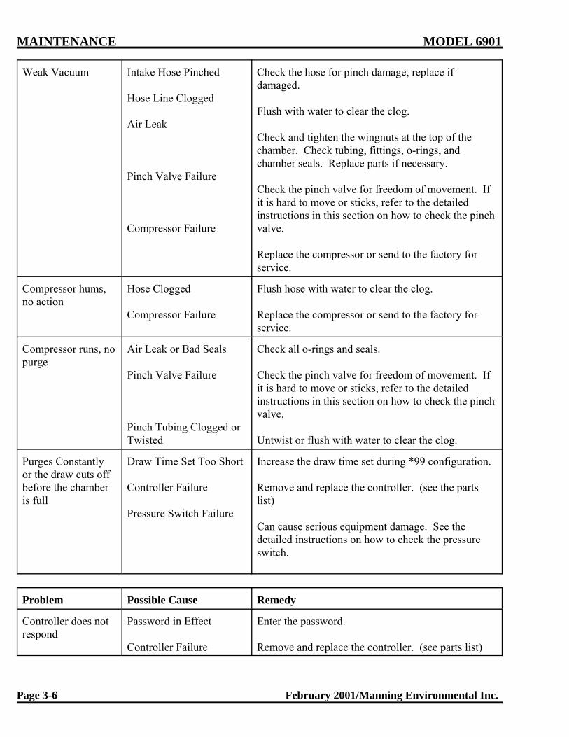
MAINTENANCE MODEL 6901
Page 3-6 February 2001/Manning Environmental Inc.
Weak Vacuum Intake Hose Pinched
Hose Line Clogged
Air Leak
Pinch Valve Failure
Compressor Failure
Check the hose for pinch damage, replace ifdamaged.
Flush with water to clear the clog.
Check and tighten the wingnuts at the top of thechamber. Check tubing, fittings, o-rings, andchamber seals. Replace parts if necessary.
Check the pinch valve for freedom of movement. Ifit is hard to move or sticks, refer to the detailedinstructions in this section on how to check the pinchvalve.
Replace the compressor or send to the factory forservice.
Compressor hums,no action
Hose Clogged
Compressor Failure
Flush hose with water to clear the clog.
Replace the compressor or send to the factory forservice.
Compressor runs, nopurge
Air Leak or Bad Seals
Pinch Valve Failure
Pinch Tubing Clogged orTwisted
Check all o-rings and seals.
Check the pinch valve for freedom of movement. Ifit is hard to move or sticks, refer to the detailedinstructions in this section on how to check the pinchvalve.
Untwist or flush with water to clear the clog.
Purges Constantlyor the draw cuts offbefore the chamberis full
Draw Time Set Too Short
Controller Failure
Pressure Switch Failure
Increase the draw time set during *99 configuration.
Remove and replace the controller. (see the partslist)
Can cause serious equipment damage. See thedetailed instructions on how to check the pressureswitch.
Problem Possible Cause Remedy
Controller does notrespond
Password in Effect
Controller Failure
Enter the password.
Remove and replace the controller. (see parts list)

MODEL 6901 MAINTENANCE
February 2001/Manning Environmental Inc. Page 3-7
Keypad inoperative Membrane Switch Failure Remove and replace the membrane switch (see partslist)
*99 self-test error Controller Failure Remove and replace the controller. (see parts list)
Forgotten Password N/A Call Manning Service Department
PARTS LISTThe following is a partial list of the spare parts available from the Manning Environmental. To order a partor for more information on a part number not listed, call the Manning Parts Department at 800-863-9337.
CAUTION: Non-Toxic refers to General Sampling; Toxic refers to Priority Pollutant Sampling.
1. SB to MB Conversion Kit 3/8" ID (select bottle configurations below)P/N 889770 Includes: (used for both Non-Toxic and Toxic)
-distribution assembly -spout assembly-distribution assembly holders -instruction drawing-miscellaneous hardware
Bottle Configuration Kits (must select one)P/N 889655 (Non-Toxic) 24, 500 ml polyethylene bottles w/Bottle Positioning PlateP/N 889656 (Non-Toxic) 24, 1000 ml polyethylene bottles w/Bottle Positioning PlateP/N 889680 (Non-Toxic) 8, 2000 ml polyethylene bottles w/Bottle Positioning PlateP/N 889657 (Toxic) 24, 350 ml glass bottles w/Bottle Positioning PlateP/N 889658 (Toxic) 8, 2000 ml glass bottles w/Bottle Positioning Plate
2. MB to SB Conversion Kit 3/8" ID (select bottle & measuring chamber below) P/N 889666 Includes: (For non-toxic conversions)
-Bottle Full Sensors -Bottle Full Sensor HarnessP/N 889667 Includes: (For toxic conversions)
-Bottle Full Sensor -Bottle Full Sensor Harness
3. NT to T Conversion Kit 3/8" ID (select bottle configurations below)P/N 889676 Includes: (used for Single Bottle)
-Toxic Chamber Top -Toxic Chamber Base-Glass Measuring Chamber -25' Teflon lined hose w/SS Strainer-Instruction Drawing
P/N 889664 Includes: (used for Multi-Bottle)-Toxic Chamber Top -Toxic Chamber Base-Glass Measuring Chamber -25' Teflon lined hose w/SS Strainer-Instruction Drawing
Bottle Configuration Kits

MAINTENANCE MODEL 6901
Page 3-8 February 2001/Manning Environmental Inc.
P/N 889715 2.5 gallon glass bottle, with Teflon lid linerP/N 889141 24, 350 ml glass bottlesP/N 889608 8, 2000 ml glass bottles
BOTTLES & RELATED SPARE PARTS
P/N 687535 5 Gallon polyethylene bottle w /capP/N 889804 5 Gallon HDPE pail w/ sealP/N 889715 2.5 Gallon glass bottle, w/ Teflon lid linerP/N 889141 350 ml glass bottle set w/ Teflon-lined caps - (24 ea)P/N 889041 500 ml polyethylene bottle set w/ caps - (24 ea)P/N 889117 1000 ml polyethylene bottle set w/ caps - (24 ea)P/N 889713 2000 ml polyethylene bottle set w/ caps - (8 ea)P/N 889608 2000 ml glass bottle set w/ Teflon-lined caps - (8 ea)P/N 687552 2000 ml glass bottle (1 ea)P/N 687533 1000 ml polyethylene bottle (1 ea)P/N 687543 500 ml polyethylene bottle (1 ea)P/N 687538 350 ml glass bottle (1 ea)P/N 564241 500 ml and 1000 ml bottle cap (1 ea)P/N 579577 Teflon Lid Liner for 350 ml glass bottle (1 ea)P/N 579959 Teflon Lid Liner for 2 liter glass bottle (1 ea)P/N 579977 Teflon Lid Liner for 2.5 gallon bottle (1 ea)
BOTTLE FULL SENSOR
P/N 889821 3/8" Bottle Full Sensor (for Toxic or Non-Toxic)P/N 889830 5/8" Bottle Full Sensor (for Toxic or Non-Toxic)P/N 818029 Bottle Full Sensor Harness
DISTRIBUTION SPARE PARTS
P/N 889081 PVC Spout Assembly, 3/8" IDP/N 889701 PVC Spout Assembly, 5/8" ID P/N 889707 Stepper Motor Sub-assemblyP/N 552042 3/8" ID Upper UnionP/N 552093 5/8" ID Upper UnionP/N 542202 O-ring, Upper UnionP/N 542186 O-ring, Upper Union
SUSPENSION PLATE PARTS
P/N 889689 Suspension Plate, 24-bottleP/N 889614 Suspension Plate, 8-bottleP/N 542224 O-ring, Suspension PlateP/N 612991 Cable Tie, Pushbutton

MODEL 6901 MAINTENANCE
February 2001/Manning Environmental Inc. Page 3-9
HOSE & STRAINER ASSEMBLY
P/N 889147 3/8" PVC Strainer (Non-Toxic)P/N 579591 3/8" Stainless Steel StrainerP/N 889815 3/8" Clear PVC Hose w/ PVC Strainer - 10'P/N 889818 3/8" Clear PVC Hose w/ PVC Strainer - 25'P/N 889816 3/8" Clear PVC Hose w/ SS Strainer - 10'P/N 889817 3/8" Clear PVC Hose w/ SS Strainer - 25'P/N 889814 3/8" Reinforced Hose w/ PVC Strainer - 10'P/N 889064 3/8" Reinforced Hose w/ PVC Strainer - 25' P/N 889813 3/8" Reinforced Hose w/ SS Strainer - 10'P/N 889773 3/8" Reinforced Hose w/ SS Strainer - 25'P/N 889810 3/8" Teflon Hose w/ SS Strainer - 10'P/N 889673 3/8" Teflon Hose and SS Strainer, 25' - ToxicP/N 552018 5/8" PVC Strainer ( Non-Toxic)P/N 889850 5/8" Clear PVC Hose w/ PVC Strainer - 10'P/N 889851 5/8" Clear PVC Hose w/ PVC Strainer - 25'P/N 889852 5/8" Reinforced Hose w/ PVC Strainer - 10'P/N 889853 5/8" Reinforced Hose w/ PVC Strainer - 25'
BULK HOSE(Bulk hose is sold by the inch)
P/N 566917 3/8" ID Clear PVC HoseP/N 566906 3/8" ID Nylon Reinforced PVC HoseP/N 566918 5/8" ID Clear PVC HoseP/N 566901 5/8" ID Nylon Reinforced PVC HoseP/N 566920 3/8" ID Teflon-lined hose
HOSE CONNECORS
P/N 552039 Female Quick-Disconnect Coupling (used with all 3/8" ID Non-Toxic hose)P/N 579518 5/8" ID Threaded Connector (used with all 5/8" ID Non-Toxic hose)
PINCH BRACKET SPARE PARTS
P/N 889665 Pinch Bracket AssemblyP/N 640525 Pinch Solenoid P/N 548034 Pinch SpringP/N 579497 Pull BarP/N 579567 Pinch BarP/N 579507 Threaded Chamber Hold-Down Rod
AIR AND DISCHARGE (PINCH) TUBING, ASSEMBLIES, AND FITTINGS

MAINTENANCE MODEL 6901
Page 3-10 February 2001/Manning Environmental Inc.
P/N 655900 Tubing, Air, Pressure SwitchP/N 566905 3/8" ID Pinch Tubing P/N 889683 Chamber Base Assembly, 3/8" ID, Non-Toxic Muli-Bottle Sampler P/N 889686 Chamber Base Assembly, 3/8" ID, Non-Toxic Single-Bottle Sampler P/N 566919 5/8" ID Pinch TubingP/N 889827 Chamber Base Assembly, 5/8" ID, Non-Toxic Muli-Bottle Sampler P/N 889826 Chamber Base Assembly, 5/8" ID, Non-Toxic Muli-Bottle Sampler P/N 566911 Clear Air Tubing (6901AC)P/N 566913 Blue Air Tubing (6901AC)P/N 566911 Clear Air Tubing (6901AC)P/N 566915 Blue Air Tubing (6901DC)P/N 566916 Red Air Tubing (6901DC)P/N 552175 Air Tubing Fitting, Quick-Disconnect, 90-Degree Elbow, Coarse ThreadP/N 552177 Air Tubing Fitting, Quick-Disconnect, 90-Degree Elbow, Fine ThreadP/N 552101 Air Tubing Fitting, Quick-Disconnect, Straight, Coarse Thread P/N 552176 Air Tubing Fitting, Quick-Disconnect, Straight, Fine Thread P/N 552087 Fitting, Barbed (Used with 655900)P/N 552174 Fitting, Compression, 90-Degree Elbow (6901AC)P/N 552097 Air Tubing Fitting, Quick-Disconnect, 3/8" ID, Straight (6901AC)P/N 552098 Air Tubing Fitting, Quick-Disconnect, 3/8" ID, 90-Degree Elbow (6901AC) P/N 787812 Y-Connector, Air Tubing
ELECTRONIC/CONTROLLER SPARE PARTS
P/N 886313 Standard Controller Assembly (6901AC)P/N 886314 Analog Controller Assembly (6901AC)P/N 889779 Standard Controller Assembly (6901DC)P/N 886786 Analog Controller Assembly (6901DC)P/N 886290 Processor BoardP/N 889182 Display AssemblyP/N 761612 Ribbon Cable Assembly, DisplayP/N 886294 Power and I/O Board (6901AC)P/N 886301 Power and I/O Board (6901DC)P/N 886158 Alarm BoardP/N 810055 Ribbon Cable Assembly, 16-Wire, Alarm Board to ControllerP/N 889196 Analog BoardP/N 810035 Ribbon Cable, 14-wire, Analog ControllerP/N 889076 Ribbon Cable, 16-wire, Analog Controller P/N 889199 Analog Upgrade Kit (Analog Board and Ribbon Cables)P/N 675561 Keypad Assembly (Keypad mounted on rectangular backer) P/N 540066 Controller Gasket, RectangularP/N 889829 Audio Indicator AssemblyP/N 640541 Transformer AC (6901AC)P/N 675416 Line Filter, Power (6901AC)P/N 640537 Power Supply, Switching, 12VDC (6901DC)P/N 638574 On/Off Switch/Circuit Breaker, Rectangular

MODEL 6901 MAINTENANCE
February 2001/Manning Environmental Inc. Page 3-11
P/N 675427 Indicator Lamp, 120 VAC, AmberP/N 783027 Zerust Vapor Barrier Capsule
MEASURING ASSEMBLY SPARE PARTS
P/N 579555 Measuring Chamber - Non-ToxicP/N 687539-1 Measuring Chamber, Glass - ToxicP/N 889703 5/8" ID Chamber Top (6958)P/N 889718 3/8" ID Chamber Top - Non-Toxic (6901AC)P/N 889719 3/8" ID Chamber Top - Toxic (6901AC)P/N 889727 3/8" ID Chamber Top - Non-Toxic (6901DC) P/N 889688 3/8" ID Chamber Top Subassembly, Non-toxic (no air fittings)P/N 638522 Pressure Switch AssemblyP/N 656868 Check Valve, Air, Fine Thread (6901AC)P/N 565869 Check Valve, Air, Coarse Thread (6901AC)P/N 579409 Float Seal, Chamber TopP/N 542180 O-Ring, Chamber TopP/N 542187 O-Ring, Chamber BaseP/N 552038 Inlet, 3/8" ID Non-Toxic Chamber Top (also used on short intake hose- mates with 552039)P/N 542229 O-Ring, Chamber Top Inlet, 3/8" ID Non-Toxic Chamber Top
MECHANICAL SPARE PARTS
P/N 889720 Stationary Sampler Maintenance Kit (6901AC)P/N 889709 Stationary Sampler Maintenance Kit (6901DC) P/N 675415 Compressor, 120VAC (6901AC)P/N 675544 Compressor, 220VAC (6901AC)P/N 675504 Compressor, 12VDC (6901DC)P/N 565861 4-Way Air Valve, 120VAC (6901AC)P/N 565867 4-Way Air Valve, 220VAC (6901AC)P/N 565864 3-Way Air Valve, 12VDC (6901DC)
MISCELLANEOUS
P/N 889013 Refrigerator, White Enamel, 120VACP/N 889049 Refrigerator, Stainless Steel, 120VACP/N 717699 Instruction Manual.

MODEL 6901 APPENDICES
February 2001/Manning Environmental Inc. A-1
Appendix AHow to Return Equipment
Contact the Manning Environmental Service Department before returning any equipment for repair. Manyproblems can be diagnosed and resolved over the telephone. Manning will issue a Return MaterialAuthorization (RMA) number if it is deemed necessary that the equipment be returned for repair.
If you do need to return equipment, follow these guidelines:
• Pack equipment carefully, preferably in the original carton.
• Enclose specific information about the problem.
• Enclose a contact name and phone number in case our Factory Service Department needs additionalinformation.
• Enclose a purchase order authorizing repairs.
• Ship the equipment to the address below. Our Receiving Department will not accept collect shipments.
The Service Department phone number is (800) 863-9337. The Service Department will notify you of thetype of repair needed and an estimate of how much the repair will be. Manning will ask for authorizationbefore proceeding.
Address For Repairs:
Manning Environmental, Inc.c/o Service Department401 West 8th St.Georgetown, Texas 78626

APPENDICES MODEL 6901
February 2001/Manning Environmental Inc.A-2
Appendix BDisplay Function Chart
The Model 6901 sampler is capable of performing a program status review or a sampler configurationreview. Where the user is within the programming of the unit (PROGRAM OR NON PROGRAM MODE)will determine what status indicators are displayed.
PROGRAM MODE:The sampler possesses the ability to review the status of a program while it is in progress. This is useful ifthe operator wants to determine whether certain parameters have been met, such as how much time is left ina Time Override, for example. While in a program mode the user presses the DISPLAY key. The firststatus indicator will appear (see charts for which displays will appear with each program). Each time theDISPLAY key is pressed after that the next status indicator in sequence will be shown. If the DISPLAYkey is not pressed for 6 seconds the unit will time out and return to the active program mode display. Thenext time the user presses the DISPLAY key, the status indicator that was being shown when the samplertimed out, will appear. For example, assume the status indicator "Time Override 00:00" is being shown andthe unit times out. The next time the DISPLAY key is pressed the unit would return to the "Time Override00:00" status indicator display. The user would then have to press the DISPLAY key to continue to scrollthrough the status indicators.
NON PROGRAM MODE:The 6901 is also capable of reviewing the configuration information (*99 mode) of the sampler. Pressingthe DISPLAY key while not in a program mode (the display will be showing the SAMPLER READYprompt) will allow the user to view the information entered when the sampler was configured. Theoperation works exactly the same as the PROGRAM MODE above except that once the sampler times out,it will return to the SAMPLER READY display.
The following grid charts detail which displays are active with each program mode:

MODEL 6901 APPENDICES
February 2001/Manning Environmental Inc. A-7
Appendix COptional Wall Mounting
Wall Mount
This option allows the sampler enclosure to pivot out from the wall so that you can access the electronicswithout removing the sampler from the mountings.
If you ordered the wall mount option with your sampler, you will received hardware and more detaileddrawings with the wall mount.
Figure A-1 shows the wall mount option.
Figure A-1 Wall Mount Option

APPENDICES MODEL 6901
February 2001/Manning Environmental Inc.A-8
Appendix DOptional Leg Mounts
Leg Mount
Figure A-2 shows the leg mounts available for the Model 6901. If you ordered this option, you will receivehardware and more detailed drawings with your order.
Figure A-2 Leg Mount Option

MODEL 6901 APPENDICES
February 2001/Manning Environmental Inc. A-9
Appendix EHeater Option
Heater Option
Manning does not recommend operation of the sampler in temperatures below 32ºF. With out heaters and/orother environmental protection. Manning offers optional heaters for both the electronics enclosure and therefrigerator. The heater consists of a thermal blanket mounted on a metal bracket with a thermostat.
In conditions where the temperature is expected to remain below freezing for extended periods of time,Manning recommend the optional NEMA3 sampler enclosure with heater.
The heater is a factory-installed option..
Figure A-3 Heater Option

APPENDICES MODEL 6901
February 2001/Manning Environmental Inc.A-10
Appendix FAlarm Option
Alarm Option
There are several alarm options available, all of which are factory installed. The main part of the alarmoption the Alarm Board, which is mounted to the back of the central panel. It is connected to the controllerby a 16-wire ribbon cable. The alarm board is capable of providing 2 sets of 5A normally-open relaycontacts for each of the following conditions:
1) Sample Cycle- The relay contacts are closed during the sample cycle. 2) Missed Sample- The relay contacts are closed if a sample is missed. (The chamber was not filled in
either of the two draw attempts during a sample cycle. The relay contacts open at the beginning of thenext sample cycle).
3) Bottle Full or End of Sequence. For single-bottle samplers, the relay contacts are closed when a bottle full condition is sensed. For muli-bottle samplers, the relay contact are closed when after the last
sample is deposited into the last bottle- the end of the sample program sequence.
Normally, a lamp is mounted on the front door of the enclosure for each alarm installed. Additionally, anaudio alarm can be added. Both the lamps and the audio alarms are AC-powered, so they can share thesame set of contacts. This leaves the second set of contacts free for customer use.

MODEL 6901 APPENDICES
February 2001/Manning Environmental Inc. A-11
Figure A-4 Alarm Option

APPENDICES MODEL 6901
February 2001/Manning Environmental Inc.A-12
Appendix GAdditional Drawings

MODEL 6901 APPENDICES
February 2001/Manning Environmental Inc. A-13
THIS PAGE INTENTIONALLY LEFT BLANK

PARTS LIST6901 Stationary
Vacuum SamplerThe following is a partial list of the spareparts available from the ManningEnvironmental Parts Department. Toorder a part or for more information on apart number not listed, call the ManningParts Department at 800-863-9337.
CAUTION: Non-Toxic refers to GeneralSampling; Toxic refers to Priority PollutantSampling.
1. SB to MB Conversion Kit (does notinclude bottles)PN# 889770 Includes: (used for bothNon-Toxic and Toxic)-stepper motor-spout assembly-left & right BPP hangers-chamber base-miscellaneous hardware-instruction drawing
Bottle Configuration KitsPN# 889655 (Non-Toxic) 24, 500 ml polyethylene bottles w/BottlePositioning Plate
PN# 889656 (Non-Toxic) 24, 1000 mlpolyethylene bottles w/Bottle PositioningPlate
PN# 889680 (Non-Toxic) 8, 2000 mlpolyethylene bottles w/Bottle PositioningPlate
PN# 889657 (Toxic) 24, 350 ml glassbottles w/Bottle Positioning Plate
2. MB to SB Conversion Kit PN# 889774 Includes:(For non-toxic conversions does notinclude bottle)-Bottle Full Sensors-Bottle Full Sensor Harness-Chamber Base
Bottle Configuration Kits PN# 889715 2.5 gallon glass bottle, withTeflon lid liner
BOTTLES & RELATED SPAREPARTS
PN# 687535 5 Gallon polyethylene bottlew /capPN# 889804 5 Gallon HDPE pail w/ seal
PN# 687547 2.5 gallon polyethylenebottle w/cap
PN# 687551 4 gallon polyethylene bottlew/cap
PN# 889689 24 Bottle Positioning plate
PN# 889614 8 bottle positioningplate (shown without handles)
1 Liter Bottle - Left500ml Bottle - Right
PN# 889141 350 ml glass bottle set w/Teflon-lined caps - (24 ea)
PN# 889041 500 ml polyethylene bottleset w/ caps - (24 ea)
PN# 889117 1000 ml polyethylene bottleset w/ caps - (24 ea)
PN# 889713 2000 ml polyethylene bottleset w/ caps - (8 ea)
PN# 889608 2000 ml glass bottle set w/Teflon-lined caps - (8 ea)
PN# 687552 2000 ml glass bottle (1ea)
PN# 687533 1000 ml polyethylene bottle(1ea)
PN# 687534 500 ml polyethylene bottle(1ea)
PN# 687538 350 ml glass bottle (1ea)
PN# 564241 500ml bottle cap (1ea)
PN# 564241 1000ml bottle cap (1ea)
PN# 579577 Teflon Lid liner for 350ml glass bottle (1ea)
PN# 579959 Teflon Lid liner for 2 literglass bottle (1ea)
PN# 579977 Teflon Lid liner for 2.5gallon glass bottle (1ea)
DISTRIBUTION SPARE PARTSELECTRONIC/ CONTROLLER
PN# 540066 - Gasket for 6901Keypad (Gasket only, no backer or
keypad)
PN# 638577 - 6901 Keypad (Keypadonly, no gasket or backer)
Not ShownPN# 423735 - Backer for 6901 Keypad

DC ONLY
PN# 889196 - AnalogBoard
PN# 889199 - AnalogUpgrade (includes
necessary cables - PN#889076 & 810035)
DC ONLY
PN# 886290 - CPU Board
DC ONLY
PN# 886301 - Power Board
PN# 889768 - Analog Controller withoutHousing
PN# 889779 - Standard Controller withoutHousing
PN# 601851Lithium Battery
SPARE PARTSHOSE & STRAINER ASSEMBLY
Various Strainers (Leftto Right)
PN# 552018 - 5/8" PVCPN# 889147 - 3/8" PVCPN# 579591 - 3/8" AllStainless Steel
Various Hoses (Left to Right)
PN# 566905 - 3/8" Pinch Tubing
PN# 566917 - 3/8" Clear PVC IntakeNot Shown
PN# 566918 - 5/8" Clear PVC Intake
PN# 566920 - 3/8" Teflon LinedPolyethylene
Not ShownPN# 566902 - 5/8" Teflon linedPolyethylene
PN# 566919 - 5/8" Pinch Tubing
PN# 566899 - 5/8" Pinch Tubing for5200 & 5000 Series Stationary Units
PN# 566906 - 3/8" Braided PVC Intake
PN# 566901 - 5/8" Braided PVC Intake
PN# 566917 3/8" Clear PVC Hose(purchased by inch)PN# 889815 3/8" Clear PVC Hose w/PVC Strainer - 10'PN# 889818 3/8" Clear PVC Hose w/PVC Strainer - 25'PN# 889816 3/8" Clear PVC Hose w/ SSStrainer - 10'PN# 889817 3/8" Clear PVC Hose w/ SSStrainer - 25'PN# 889814 3/8" Reinforced Hose w/PVC Strainer - 10'PN# 889064 3/8" Reinforced Hose w/PVC Strainer - 25' PN# 889813 3/8" Reinforced Hose w/ SSStrainer - 10'PN# 889773 3/8" Reinforced Hose w/ SSStrainer - 25'PN# 889810 3/8" Teflon Hose w/ SSStrainer - 10'PN# 889673 3/8" Teflon Hose and SSStrainer, 25' - Toxic
PN# 552039 - Quick DisconnectHose Fittings
PN# 552038 -Male Fitting
for QuickDisconnect
PN# 889828 - Short HoseAssembly (6901)
MISCELLANEOUSPN# 717699 Instruction Manual
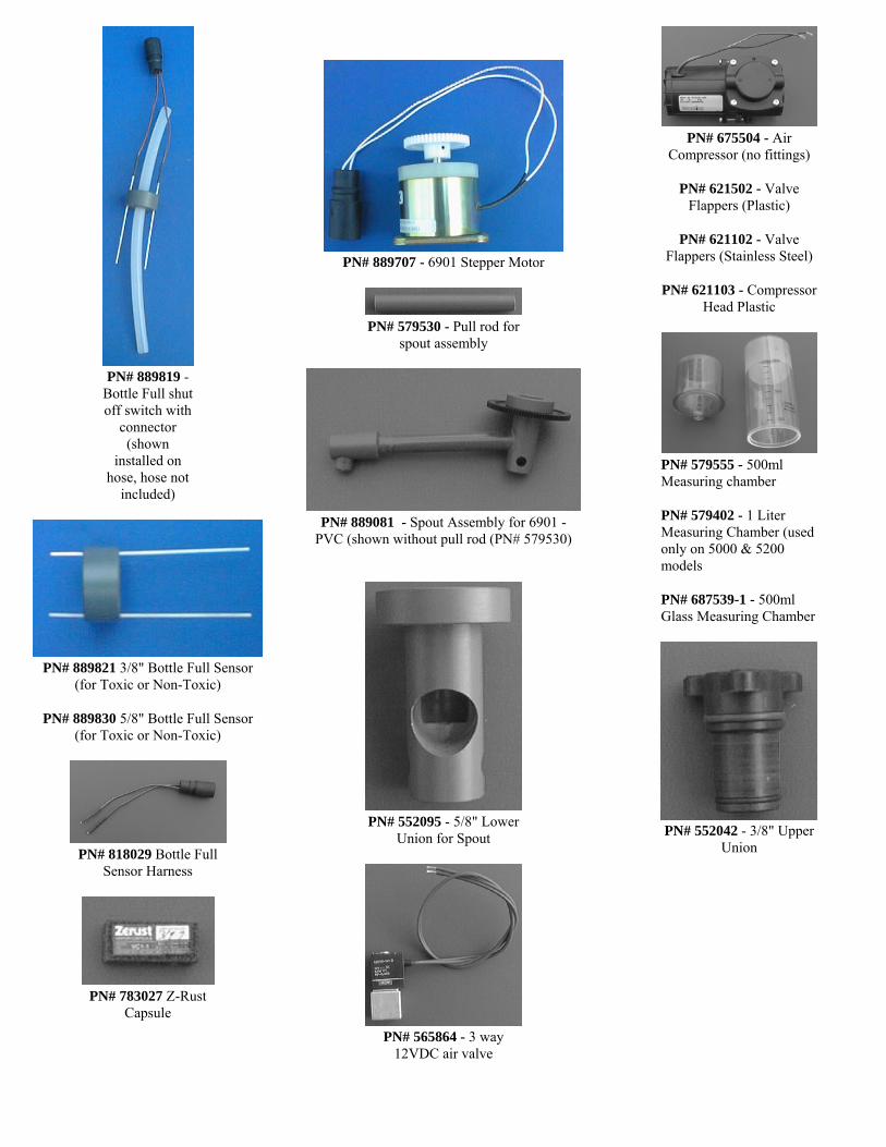
PN# 889819 -Bottle Full shutoff switch with
connector(shown
installed onhose, hose not
included)
PN# 889821 3/8" Bottle Full Sensor(for Toxic or Non-Toxic)
PN# 889830 5/8" Bottle Full Sensor(for Toxic or Non-Toxic)
PN# 818029 Bottle FullSensor Harness
PN# 783027 Z-RustCapsule
PN# 889707 - 6901 Stepper Motor
PN# 579530 - Pull rod forspout assembly
PN# 889081 - Spout Assembly for 6901 -PVC (shown without pull rod (PN# 579530)
PN# 552095 - 5/8" LowerUnion for Spout
PN# 565864 - 3 way12VDC air valve
PN# 675504 - AirCompressor (no fittings)
PN# 621502 - ValveFlappers (Plastic)
PN# 621102 - ValveFlappers (Stainless Steel)
PN# 621103 - CompressorHead Plastic
PN# 579555 - 500mlMeasuring chamber
PN# 579402 - 1 LiterMeasuring Chamber (usedonly on 5000 & 5200models
PN# 687539-1 - 500mlGlass Measuring Chamber
PN# 552042 - 3/8" UpperUnion

DC ONLY
PN# 889727 - 3/8" Chamber Top(shown without fittings)
PN# 889703 - 5/8" Chamber Topwith Magnetic Float Switch
PN# 579397 - 5/8"Chamber Base
PN# 889826 - 5/8"Chamber Base with PinchTubing (4901)
PN# 889827 - 5/8"Chamber Base with PinchTubing (6901)
PN# 889686 - 3/8"Chamber Base with PinchTubing - Single Bottle6901 Series
PN# 889683 - 3/8"Chamber Base with PinchTubing - Multiple Bottle6901 Series
PN# 889684 - 3/8" AllConfigurations 4901
PN# 638560 Chamber Full Shut-offswitch
PN# 579499 - 5/8" SpiralTube
PN# 579498 - 5/8" SlottedTube (Not Shown)
Various Collets shown left to right
PN# 579515PN# 552097PN# 552098PN# 552101PN# 555176PN# 552177
OLD STYLEAC ONLY
PN# 565868 -Check Valve
PN# 565869 -Check Valve

Various Items (Left to Right)
PN# 579576 - Pinch Bar
PN# 552067 - 3/8" ToxicSlotted Tube
PN# 579501 - 3/8" Slotted Tube
PN# 579500 - 3/8" Spiral Tube
PN# 579496 - 3/8" ChamberBase
PN# 889707 - Stepper Motor PN# 889829 - Buzzer forKeypad
PN# 889831 - 3/8" Bottle FullSensor
PN# 542180 - O-RingChamber Top 4901/6901 PN# 542186 - O-RingPN# 542187 - O-RingChamber Base 4901/6901 PN# 542216 - O-RingPN# 542224 - O-RingPN# 542225 - O-RingPN# 542226 - O-RingPN# 542227 - O-RingPN# 542229 - O-Ring
PN# 889709 -Maintenance Kit - 6901
PN# 640525 - PinchSolenoid with throw rod
PN# 889665 - Pinch Valve Assembly
PN# 579553 - Bounce Pad for PinchValve Assembly (Not shown)
PN# 579576 - Pinch Bar for Pinch ValveAssembly (Not shown)
PN# 579497 - Pull Bar for Pinch ValveAssembly - 4901/6901 (Not shown)
PN# 548015 - Pinch Spring for5000 series samplers (stationary)
PN# 548031 - Pinch Spring for5000 series samplers (stationary)
PN# 548034 - Pinch Spring (4901& 6901)
PN# 638541 - Pressure Switch
OLD STYLEAC ONLY
PN# 564861 - 4 WayValve
PN# 889888 Fiberglass refrigeratorCover

889702 (shown with spout which isnot included in 889702) installed on
24 bottle suspension plate
PN# 889702 Distribution assembly withstepper motor and bracket (Spout not
included)
PN# 545059 RefrigeratorPlug
Refrigerator - drilled and tapped.
PN# 889013 Standard 110VACRefrigerator
PN# 889049 Stainless Steel 110VACRefrigerator
PN# 889016 Standard 220VACRefrigerator
PN# 889051 Stainless Steel 220VACRefrigerator

Feb
ruar
y 20
01/M
ann
ing
En
viro
nm
enta
l, In
c.
A
-3
TIM
EPR
OG
RA
MS
FIR
ST A
T__
:__
LAST
AT
__:_
_
TIM
E D
IFF
__:_
_A
CTI
VE
TIM
E_:
__:_
_
THE
SPO
UT
IS P
OIN
TED
AT
BO
TTLE
__
TIM
E TO
NEX
TSA
MPL
E__
:__
ATT
EMPT
EDSA
MPL
E =
__V
ALI
D _
MIS
SED
_
THE
PRO
GR
AM
HA
S B
EEN
DEL
AY
EDFO
R _
_:__
THIS
BO
TTLE
CO
NTA
INS
_ SA
MPL
ES
SAM
PLES
AR
ETA
KEN
EVER
Y _
_FL
OW
PU
LSES
BO
TTLE
AC
TIV
EPE
RIO
D__
:__
TIM
EO
VER
RID
E__:
__
THE
NEX
TSA
MPL
EW
ILL
OC
CU
R IN
__ _
_:__
__
AC
TIV
EG
RO
UP
PER
IOD
__:
__
* St
art
TT
TT
TT
STI
TT
TT
TT
STI w
/ DS
TT
TT
TT
T
STI w
/ MB
TT
TT
TT
STI w
/ MS
TT
TT
TT
STI w
/ MB
& D
ST
TT
TT
T
STI w
/ MB
& D
ST
TT
TT
TT
STI w
/ MS
& D
ST
TT
TT
TT
STI =
Sin
gle
Tim
e In
terv
alM
B =
Mul
ti B
ottle
MS
= M
ulti
Sam
ple
DS
= D
elay
Sta
rt

Feb
ruar
y 20
01/M
ann
ing
En
viro
nm
enta
l, In
c.
A
-4
FLO
WPR
OG
RA
MS
FIR
ST A
T__
:__
LAST
AT
__:_
_
TIM
E D
IFF
__:_
_A
CTI
VE
TIM
E_:
__:_
_
THE
SPO
UT
IS P
OIN
TED
AT
BO
TTLE
__
TIM
E TO
NEX
TSA
MPL
E__
:__
ATT
EMPT
EDSA
MPL
E =
__V
ALI
D _
MIS
SED
_
THE
PRO
GR
AM
HA
S B
EEN
DEL
AY
EDFO
R _
_:__
THIS
BO
TTLE
CO
NTA
INS
_ SA
MPL
ES
SAM
PLES
AR
ETA
KEN
EVER
Y _
_FL
OW
PU
LSES
BO
TTLE
AC
TIV
EPE
RIO
D__
:__
TIM
EO
VER
RID
E__:
__
THE
NEX
TSA
MPL
EW
ILL
OC
CU
R IN
__ _
_:__
__
AC
TIV
EG
RO
UP
PER
IOD
__:
__
Flow
Mod
eT
TT
TT
Flow
w/ D
ST
TT
TT
T
Flow
w/ M
BT
TT
TT
Flow
w/ M
ST
TT
TT
Flow
w/ M
B&
DS
TT
TT
TT
Flo
w w
/ MS
& D
ST
TT
TT
T
MB
= M
ulti
Bot
tleM
S =
Mul
ti Sa
mpl
eD
S =
Del
ay S
tart

Feb
ruar
y 20
01/M
ann
ing
En
viro
nm
enta
l, In
c.
A
-5
* M
OD
EPR
OG
RA
MS
FIR
ST A
T__
:__
LAST
AT
__:_
_
TIM
E D
IFF
__:_
_A
CTI
VE
TIM
E_:
__:_
_
THE
SPO
UT
IS P
OIN
TED
AT
BO
TTLE
__
TIM
E TO
NEX
TSA
MPL
E__
:__
ATT
EMPT
EDSA
MPL
E =
__V
ALI
D _
MIS
SED
_
THE
PRO
GR
AM
HA
S B
EEN
DEL
AY
EDFO
R _
_:__
THIS
BO
TTLE
CO
NTA
INS
_ SA
MPL
ES
SAM
PLES
AR
ETA
KEN
EVER
Y _
_FL
OW
PU
LSES
BO
TTLE
AC
TIV
EPE
RIO
D__
:__
TIM
EO
VER
RID
E__:
__
THE
NEX
TSA
MPL
EW
ILL
OC
CU
R IN
__ _
_:__
__
AC
TIV
EG
RO
UP
PER
IOD
__:
__
* 01
TT
TT
TT
T
*02
TT
TT
TT
*02
w/ D
SD
SDS
T
TT
TT
TT
*02
w/ M
BT
TT
TT
T
*02
w/ M
ST
TT
TT
TT
*02
w/
MB
&D
S T
TT
TT
TT
*02
w/
MS&
DS
TT
TT
TT
T
*04
TT
TT
TT
T
*04
w/ D
ST
TT
TT
TT
T
*04
w/ M
BT
TT
TT
TT
*04
w/ M
ST
TT
TT
TT
*04
w/
MB
&D
S T
TT
TT
TT

Feb
ruar
y 20
01/M
ann
ing
En
viro
nm
enta
l, In
c.
A
-6
* M
OD
EPR
OG
RA
MS
FIR
ST A
T__
:__
LAST
AT
__:_
_
TIM
E D
IFF
__:_
_A
CTI
VE
TIM
E_:
__:_
_
THE
SPO
UT
IS P
OIN
TED
AT
BO
TTLE
__
TIM
E TO
NEX
TSA
MPL
E__
:__
ATT
EMPT
EDSA
MPL
E =
__V
ALI
D _
MIS
SED
_
THE
PRO
GR
AM
HA
S B
EEN
DEL
AY
EDFO
R _
_:__
THIS
BO
TTLE
CO
NTA
INS
_ SA
MPL
ES
SAM
PLES
AR
ETA
KEN
EVER
Y _
_FL
OW
PU
LSES
BO
TTLE
AC
TIV
EPE
RIO
D__
:__
TIM
EO
VER
RID
E__:
__
THE
NEX
TSA
MPL
EW
ILL
OC
CU
R IN
__ _
_:__
__
AC
TIV
EG
RO
UP
PER
IOD
__:
__
*04
w/
MS&
DS
DS
TT
TT
TT
T
*05
TT
TT
TT
*05
w/ M
BT
TT
TT
T
*05
w/ M
ST
TT
TT
T
*06
TT
TT
T
*06
w/ M
BT
TT
TT
*06
w/ M
ST
TT
TT
*09
TT
TT
T
*09
w/ M
BT
TT
TT
T
*09
w/ M
ST
TT
TT
T
*10
TT
TT
TT
*10
w/ D
ST
TT
TT
TT
*11
TT
TT
TT
T
*12
TT
TT
TT
TT
*13
TT
TT
TT
TT
T
MB
= M
ulti
Bot
tleM
S =
Mul
ti Sa
mpl
eD
S =
Del
ay S
tart

Part Number 717699 February 2001© 2001 Manning Environmental, Inc
1904B S. Austin Ave. Georgetown, TX 78626 Phone: (800) 863-9337(512) 863-9337
Fax: (512) 863-4472