operation and maintenance manual for the digital tracking receiver
TRANSCRIPT

CG-1220 REV K
APRIL 2006
OPERATION AND MAINTENANCE MANUAL FOR THE
DIGITAL TRACKING RECEIVER
1915 Harrison Road
Longview, Texas 75604
EXPORT CONTROL WARNING - Do not disclose this document or its contents to non-U.S. Citizens, or transmit this document or its contents outside the United States without the written permission of Vertex Communications Corporation and required U.S. Government approvals.

ii
Revision History K – I/O Status updated M. Neely 4-25-06 G. Branch 4-25-06 6629 J – Freq expanded to 945-2055 M. Neely 2-06-06 G. Branch 2-06-06 6456 H – STUV freq. digits added M. Neely 11-4-05 G. Branch 11-4-05 6183 G – ECW & Diversion Stmt M. Neely 3-22-05 G. Branch 3-22-05 5718 F – Sig. Update, ATTN, etc. M. Neely 10-18-04 G. Branch 10-18-04 5468 E – For v1.19.13 M. Neely 7-21-04 G. Branch 7-21-04 5355 D – 201800 Update M. Neely 4-3-04 G Branch 4-30-04 5192 C – 4 Port Option M. Neely 10-10-03 G. Branch 10-10-03 4832 B – Misc. M. Neely 9-25-01 D. Bulgrien 9-25-01 --- A – First major release M. Neely 7-10-00 D. Bulgrien 7-10-00 --- Initial release M. Neely 1-26-00 K. Cone 1-26-00 ---
Rev. No/change Revised By Date Approved By Date ECO#

iii
NOTICES
WARNING
THE ELECTRICAL CURRENTS AND VOLTAGES IN THIS EQUIPMENT ARE DANGEROUS. PERSONNEL MUST OBSERVE SAFETY REGULATIONS AT ALL TIMES.
This manual is intended as a general guide for trained and qualified personnel who are aware of the dangers of handling potentially hazardous electrical and electronic circuits. This manual is not intended to contain a complete statement of all safety precautions that should be observed by personnel in using this or other electronic equipment.
WARNING
IN CASE OF EMERGENCY BE SURE THAT POWER IS DISCONNECTED.
The manufacturer has attempted to detail in this manual all areas of possible danger to personnel in connection with the use of this equipment. Personnel should use caution when installing, operating, and servicing this equipment. Care should be taken to avoid electrical shock, whether the hazard is caused by design or malfunction.
WARNING
ALWAYS DISCONNECT POWER BEFORE OPENING COVERS, ENCLOSURES, PANELS, OR SHIELDS. ALWAYS USE GROUNDING STICKS AND SHORT OUT HIGH VOLTAGE POINTS BEFORE SERVICING. NEVER MAKE INTERNAL ADJUSTMENTS OR PERFORM MAINTENANCE OR SERVICE WHEN ALONE OR FATIGUED.
The manufacturer is specifically not liable for any damage or injury arising from improper procedures or failure to follow the instructions contained in this manual or failure to exercise due care and caution in the installation, operation, and service of this equipment or use by improperly trained or inexperienced personnel performing such tasks. During installation and operation of this equipment, local building codes and fire protection standards must be observed.
PROPRIETARY NOTICE
All computer software, technical data, or other information pertaining to the equipment covered by this manual is proprietary to VertexRSI. Such information is transmitted in this manual or related documents for the benefit of VertexRSI customers and is not to be disclosed to other parties verbally or in writing without prior written approval of VertexRSI. Additionally, this manual may not be reproduced in whole or in part without written consent from VertexRSI.
© 2006 VertexRSI

iv
Declaration of Conformity
The VertexRSI Digital Tracking Receiver (200800/201800/201046/201700)
was tested to the following specifications and found to be in compliance with the required criteria on the indicated test date.
In accordance with the following directives:
72/23/EEC The Low Voltage Directive and its amending directives.
89/336/EEC 1999/5/EC
The Electromagnetic Compatibility Directive and its amending directives. R&TTE Directive and its amending directives.
It has been designed and manufactured to the following specifications:
IEC 61010-1:1990+A1:1992+A2:1995 EN 300339: 1998 EN 55022: 1998, Class B EN 61000-4-2: 1995 EN 61000-4-3: 1995 EN 61000-4-4: 1995 EN 61000-4-5: 1995 EN 61000-4-6: 1996 EN 61000-4-11: 1994
I hereby declare that the equipment named above, when installed according to manufacturer’s instructions, complies with the above directives and standards.
Signed: Date: April 29, 2004
VertexRSI
1915 Harrison Road Longview, TX 75604
Telephone: (903) 295-1480 Fax: (903) 295-1479

v
PREFACE
About This Manual This manual is intended for anyone who uses the VertexRSI Digital Tracking Receiver (DTR). First time users as well as experienced operators will find necessary information about features, installation and operation of the DTR. This manual contains only the information related to the DTR, and does not include information about the antenna structure, the equipment used for positioning the antenna, and other equipment peripheral to the DTR. This manual is divided into the following sections: • Section 1.0, Introduction, Identifies standard and optional features of the DTR,
and briefly outlines the components of its front and rear panels. • Section 2.0, Theory, explains the theory of operation of the DTR. • Section 3.0, Installation, outlines installation, pin-outs, setup and initial power-
up of the DTR. • Section 4.0, Operation, describes the operation of the DTR, including menu
structure, navigation and other functional details. • Section 5.0, Maintenance, provides information necessary for maintaining the
DTR. • Section 6.0, Engineering Drawings, contains the engineering drawings. • Appendix A, Technical Support, provides the user with contact information for
customer support. • Appendix B, Menu Tree, contains a complete visual representation of the menu
hierarchy. • Appendix C, Remote M&C Protocol, contains commands necessary for remote
communication with the DTR. • Appendix D, Acronyms and Abbreviations, lists the definitions of all acronyms
and abbreviations used in this manual.

vi
THIS PAGE INTENTIONALLY LEFT BLANK

Table of Contents
vii
TABLE OF CONTENTS
1.0 INTRODUCTION................................................................................. 1-1 1.1 General Information Regarding the Digital Tracking Receiver .............1-1
1.1.1 DTR Standard Features ....................................................................... 1-1 1.1.2 DTR Optional Features ........................................................................ 1-2
1.2 Controls and Indicators ................................................................1-2 1.3 Inputs and Outputs......................................................................1-3 1.4 Model Numbers ..........................................................................1-4
2.0 THEORY ........................................................................................... 2-1 2.1 Standard L-band DTR...................................................................2-1 2.2 Optional Configurations................................................................2-2
2.2.1 Dual Polarization Input......................................................................... 2-2 2.2.2 Down Converter Frequencies................................................................ 2-2
3.0 INSTALLATION AND INITIAL SETUP..................................................... 3-1 3.1 Introduction................................................................................3-1 3.2 Mechanical Installation.................................................................3-1 3.3 Input and Output Connections ......................................................3-1
3.3.1 Input/Output Interface Connector Pin-Out .............................................. 3-2 3.3.1.1 Default Configuration .......................................................... 3-2
3.3.1.1.1 Analog Output Voltage Pin-Out ...................................3-3 3.3.1.1.2 Summary Fault Output...............................................3-3 3.3.1.1.3 Beacon Select Inputs (GPIO 0-3) .................................3-4 3.3.1.1.4 General Purpose I/O...................................................3-4 3.3.1.1.5 External Pol Select Control Lines (GPIO 6-7, 4-5) ..........3-4 3.3.1.1.6 Signal Ground...........................................................3-5
3.3.1.2 Monopulse Option .............................................................. 3-5 3.3.1.2.1 Degree Command Control (GPIO 0-1, 10-15) ................3-6 3.3.1.2.2 Mute Control (GPIO 2) ...............................................3-6 3.3.1.2.3 Mute Status (GPIO 8-9) .............................................3-6
3.4 Serial Interface Hardware Configuration .........................................3-7 3.5 Initial Setup and Power-up............................................................3-9
3.5.1 Analog Voltage Output (DAC) Setup ................................................... 3-10 3.5.2 Setting up Beacons for 7134 Remote Control ....................................... 3-10 3.5.3 Controlling DTR with 72XX ACUs via Serial port................................... 3-11 3.5.4 ACU Setup ...................................................................................... 3-12

Table of Contents
viii
4.0 OPERATION ...................................................................................... 4-1 4.1 Understanding the DTR Menu Structure .........................................4-3
4.1.1 Selecting Menu Items.......................................................................... 4-3 4.1.2 What Happens When a Menu is Selected…............................................ 4-3
4.1.2.1 Selects a Submenu ............................................................. 4-3 4.1.2.2 Opens an Editor Screen ....................................................... 4-3 4.1.2.3 Executes an Action............................................................. 4-3
4.2 Main Menu Items ........................................................................4-4 4.2.1 FREQUENCY...................................................................................... 4-4 4.2.2 INPUT ATTEN .................................................................................... 4-4 4.2.3 POL SELECT ...................................................................................... 4-4
4.2.3.1 POL SELECT (Four Port Option Only)..................................... 4-5 4.2.4 STATUS MENU.................................................................................. 4-5 4.2.5 CONFIGURATION MENU ..................................................................... 4-7
4.2.5.1 COMM PARAMETERS......................................................... 4-7 4.2.5.2 RECEIVER OPERATION........................................................ 4-9 4.2.5.3 CONVERSION BANDS*..................................................... 4-10 4.2.5.4 BEACON SETUP * ............................................................ 4-10 4.2.5.5 MONOPULSE* ................................................................. 4-11 4.2.5.6 SYSTEM MEMORY ........................................................... 4-12 4.2.5.6 INTERFACE OPTIONS ....................................................... 4-13
4.2.6 ACKNOWLEDGE FAULTS .................................................................. 4-13 4.2.7 TESTS ............................................................................................ 4-14
5.0 MAINTENANCE.................................................................................. 5-1 5.1 Inspection and Preventive Maintenance ..........................................5-1 5.2 System Spares ...........................................................................5-1
6.0 ENGINEERING DRAWINGS .................................................................. 6-1
APPENDIX A, TECHNICAL SUPPORT ...........................................................A-1
APPENDIX B, MENU TREE .......................................................................... B-1
APPENDIX C, REMOTE M&C PROTOCOL .....................................................C-1
APPENDIX D, ACRONYMS & ABBREVIATIONS .............................................D-1
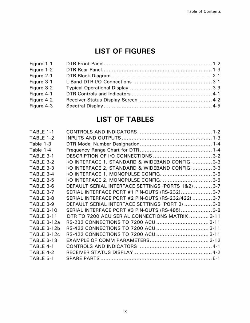
Table of Contents
ix
LIST OF FIGURES Figure 1-1 DTR Front Panel..................................................................1-2 Figure 1-2 DTR Rear Panel...................................................................1-3 Figure 2-1 DTR Block Diagram .............................................................2-1 Figure 3-1 L-Band DTR-I/O Connections ................................................3-1 Figure 3-2 Typical Operational Display ..................................................3-9 Figure 4-1 DTR Controls and Indicators .................................................4-1 Figure 4-2 Receiver Status Display Screen .............................................4-2 Figure 4-3 Spectral Display..................................................................4-5
LIST OF TABLES
TABLE 1-1 CONTROLS AND INDICATORS .............................................1-2 TABLE 1-2 INPUTS AND OUTPUTS.......................................................1-3 Table 1-3 DTR Model Number Designation............................................1-4 Table 1-4 Frequency Range Chart for DTR ............................................1-4 TABLE 3-1 DESCRIPTION OF I/O CONNECTIONS ....................................3-2 TABLE 3-2 I/O INTERFACE 1, STANDARD & WIDEBAND CONFIG. ............3-3 TABLE 3-3 I/O INTERFACE 2, STANDARD & WIDEBAND CONFIG. ............3-3 TABLE 3-4 I/O INTERFACE 1, MONOPULSE CONFIG. ..............................3-5 TABLE 3-5 I/O INTERFACE 2, MONOPULSE CONFIG. ..............................3-5 TABLE 3-6 DEFAULT SERIAL INTERFACE SETTINGS (PORTS 1&2) ...........3-7 TABLE 3-7 SERIAL INTERFACE PORT #1 PIN-OUTS (RS-232)...................3-7 TABLE 3-8 SERIAL INTERFACE PORT #2 PIN-OUTS (RS-232/422) ............3-7 TABLE 3-9 DEFAULT SERIAL INTERFACE SETTINGS (PORT 3) .................3-8 TABLE 3-10 SERIAL INTERFACE PORT #3 PIN-OUTS (RS-485)...................3-8 TABLE 3-11 DTR TO 7200 ACU SERIAL CONNECTIONS MATRIX ............ 3-11 TABLE 3-12a RS-232 CONNECTIONS TO 7200 ACU ................................ 3-11 TABLE 3-12b RS-422 CONNECTIONS TO 7200 ACU ................................ 3-11 TABLE 3-12c RS-422 CONNECTIONS TO 7200 ACU ................................ 3-11 TABLE 3-13 EXAMPLE OF COMM PARAMETERS.................................... 3-12 TABLE 4-1 CONTROLS AND INDICATORS .............................................4-1 TABLE 4-2 RECEIVER STATUS DISPLAY................................................4-2 TABLE 5-1 SPARE PARTS....................................................................5-1

Table of Contents
x
THIS PAGE INTENTIONALLY LEFT BLANK

Introduction
CG-1220 DTR 1-1
1.0 INTRODUCTION 1.1 General Information Regarding the Digital Tracking
Receiver The DTR, developed for satellite tracking, is a fully synthesized tracking receiver. The Digital Signal Processor (DSP) based receiver accepts wideband RF inputs, performs frequency selection, downconverts RF to 70 MHz, and digitally processes the digital samples. The DTR’s user interface is powerful and intuitive giving the operator the ability to custom configure specific applications in a very straight forward manner. The unit’s versatile settings allow the unit to interface with a wide range of next-level system components.
1.1.1 DTR Standard Features The following are the standard features of the DTR: • Input frequency range of 945 MHz to 2055 MHz for L-band configuration • Wide input signal dynamic range (70 dB Nominal) • Sensitivity signal range of –40 dBm to –110 dBm • Minimum C/No better than 35 dB/Hz • Synthesized tuning • Tuning resolution of 1 kHz • Selectable tracking slope • Signal linearity ( .5dB over a 10dB nominal tracking range) • Intelligent signal/side-band recognition • 240x64-pixel graphics display • User interface with logically grouped menus • Optimal mix of “dedicated and soft keys” for efficient menu navigation and data
entry • Spin knob for alternate means of tuning and adjusting parameter values • Dedicated online Help key • Remote control capability (RS-232, RS-422, RS-485, contact closures) • Front panel 70 MHz monitor port (50 Ω BNC female) • Real time spectral display of tracking signal • Field upgradable software • C/No and power measurement information display • Compatibility with TRL series L-band Tracking Receivers, including I/O interface
and serial communications protocol • Selectable input attenuator of 0 – 30 dB in 2 dB steps

Introduction
1-2 CG-1220 DTR
1.1.2 DTR Optional Features • Input frequency range covering S, C, X, Ku and Ka-band configurations • Up to 6 RF inputs • Dual polarization input • Multi-band switching • Single/dual channel monopulse tracking • Wideband operation • Complete backward compatibility with TRL series L-band Tracking Receivers,
including monopulse interfaces and TBT (Tracking Band Translator) support • Rack Slides
1.2 Controls and Indicators The controls and indicators located on the DTR front panel provide the normal operator interface. The DTR front panel is shown in Figure 1-1 with its controls and indicators identified. The function of each is detailed in Section 4, Operation.
Figure 1-1 DTR Front Panel
TABLE 1-1 CONTROLS AND INDICATORS
1. Receiver Status Display
2. Soft Keys
3. Navigation Keys
4. Status Indicators
5. Numeric Keypad
6. Spin Knob
7. IF Monitor Port

Introduction
CG-1220 DTR 1-3
1.3 Inputs and Outputs The inputs and outputs located on the DTR rear panel provide the external interfaces. The number of inputs varies with user configuration. The DTR rear panel is shown in Figure 1-2. The function of each input and output is listed in Table 1-1.
Figure 1-2 DTR Rear Panel
TABLE 1-2 INPUTS AND OUTPUTS
CONNECTOR FUNCTION
1. RF Input: Provides up to 6 selectable inputs for RF signals in the following bands:
Type N Connector • L-band • S-band • C-band • X-band • Ku-band
Type SMA Connector • Ka-band
2. I/O Interface 1 and 2 Analog Interface and Control ports. Provides analog control and status.
3. RS-232 A standard RS-232 serial port.
4. RS-422 A standard RS-422 serial port. Also configurable as an RS-232 serial port.
5. RS-485 A standard RS-485 serial port.
6. Power Supply Universal power supply accepting 100 – 240 VAC, 50/60 Hz. A fuse is accessible by pulling out a holder between the switch and the plug. This holder also contains a spare fuse.
IMPORTANT: The safety grounding bolt below the input should be securely connected to the rack ground bar (or adequate earth ground) to eliminate a potential failure hazard.


Theory
CG-1220 DTR 2-1
2.0 THEORY 2.1 Standard L-band DTR The use of advanced DSP techniques coupled with conventional analog radio techniques provides enhanced flexibility and sensitivity to the DTR. The L-Band DTR, illustrated by the block diagram in Figure 2-1, takes a RF input signal in the L-Band frequency range and down-converts the signal to a 70 MHz Intermediate Frequency (IF) using a super-heterodyne process. The signal is then routed through an anti-aliasing filter prior to being sampled by a high-speed analog to digital converter (A/D). This digital data is then passed through a decimating Finite Impulse Response (FIR) filter, which provides both a sample rate reduction and a band limiting function. The DSP chip then transforms the data using a Fast Fourier Transform (FFT) and analyzes the band for signal and noise content. The signal power and signal to noise information is estimated and the values are sent to the System Control Processor (SCP). The SCP sets and manages module functions and communication with the user and other equipment via the front panel controls and data interfaces. The SCP also makes slope adjustments and reports the received signal power level to control equipment via serial communications.
Analog toDigital
Conversion-RF Front-End DSP
MCU
DDSFrequencyReference
Control
Graphics Display(240x64-pixel)
Keypad+
SoftKeysRS-232 Serial
Ports
RS-422 SerialPorts
SRAM
FlashEEPROM
SCP
Analog/CustomerInterface I/O
I/O
16-Bit Parallel (DMA)
166X32KSynchronous
FIFO
FIRFiltering
Serial Link
Serial Link
PLL Reference(s)
Control
IFMonitor
Port
SPU
CPU
Signal of Interest DigitizedSignal Filtered Signal
FlashEEPROM
NVRAM
RS-485 SerialPort
Figure 2-1 DTR Block Diagram

Theory
2-2 CG-1220 DTR
2.2 Optional Configurations 2.2.1 Dual Polarization Input Versatile unit configurations allow dual-receive signal polarization to be connected to separate RF inputs on the DTR’s back panel. Linear polarizations (vertical and horizontal) and circular polarizations (clockwise and counter clockwise) can be connected to the DTR without external combining or switching.
2.2.2 Down Converter Frequencies RF signals enter the DTR on one of six possible inputs and are routed to the proper Block Down Converter (BDC) for conversion to an L-band signal of 950 MHz to 2050 MHz. Each band accepts an input level of –110 to –40 dBm (decibel referred to 1 milliwatt). The output of each block downconverter is connected to appropriate switching and routed to the input of the L-band downconverter. To prevent unnecessary heat and noise, the DC power to each BDC is switched so that the BDC is only powered when its particular band is selected.

Installation
CG-1220 DTR 3-1
3.0 INSTALLATION AND INITIAL SETUP 3.1 Introduction This section provides the information necessary for the installation and initial setup of the DTR. 3.2 Mechanical Installation Using four #10 screws, mount the DTR in a standard 19-inch Electronic Industries Association (EIA) equipment rack. Rear support and/or rack slides are not usually necessary; however, rack slides may prove helpful during maintenance operations and are available as an option.
3.3 Input and Output Connections Refer to Figure 3-1 for a diagram showing the possible Input/Output (I/O) connections to the DTR. Table 3-1 provides brief descriptions of each connection or group of connections.
Figure 3-1 L-Band DTR-I/O Connections

Installation
3-2 CG-1220 DTR
NOTE: ACU I/O connections shown for reference only. The DTR may be interfaced with any ACU having contact closures for beacon selection and a tracking voltage input or a serial link utilizing the DTR’s M&C command set.
TABLE 3-1 DESCRIPTION OF I/O CONNECTIONS
CONNECTION DESCRIPTION
Line POWER ENTRY MODULE
For 120 V operation, a standard 3-prong National Electrical Manufacturers Association (NEMA) plug is provided; for 220/230/240 V operation, the same power cable assembly is provided, but the customer may be required to install a more appropriate plug on site. Note that the ground conductor MUST be utilized with the line power connection.
RF INPUTS The RF inputs to the DTR are provided through 50 ohm, type N female connectors on the rear panel. The allowable input signal range is -110 decibel referred to 1 milliwatt (dBm) to -40 dBm. The DTR input Voltage Standing-Wave Ratio (VSWR) is 1.25:1, nominal. The standard receiver configuration has INPUT #1 available only. In multiband receivers, lower input numbers correspond with lower frequencies. For example, in a C and Ku receiver, Inputs 1 & 2 would be C-band and Inputs 3 & 4 would be Ku-band.
I/O INTERFACE The I/O interface provides the classic analog interface for ACU control. There are two sets of analog output signals: OUT(+,-) and AUX(+,-). Four contact lines are provided, as well as a summary fault closure. Additionally, there are several general-purpose inputs and outputs that can be used to change the receiver's operational mode. See Tables 3-2 and 3-3 for pin-outs.
SERIAL INTERFACE #1 This serial port provides a sophisticated digital control and status interface for advanced ACU and M&C systems. Interface #1 is configured for RS-232 only. Full remote control of the receiver is realized with this interface. See Table 3-7 for pin-outs.
SERIAL INTERFACE #2 This serial port provides a sophisticated digital control and status interface for advanced ACU and M&C systems. Interface #2 is fully configurable for RS-232 or RS-422. Full remote control of the receiver is realized with this interface. See Table 3-8 for pin-outs.
SERIAL INTERFACE #3 This serial port provides a sophisticated digital control and status interface for advanced M&C systems. Interface #3 is configured for RS-485 only. Full remote control of the receiver is realized with this interface. See Table 3-9 for pin-outs.
3.3.1 Input/Output Interface Connector Pin-Out The I/O Interface Connector Pin-Out section describes the signals and configuration of the I/O INTERFACE connectors (25-pin D female subminiature socket). 3.3.1.1 Default Configuration Table 3-2 and 3-3 describes the pin number, designation and function of the two I/O ports. The tables show the default configuration only.

Installation
CG-1220 DTR 3-3
TABLE 3-2 I/O INTERFACE 1, STANDARD & WIDEBAND CONFIG.
PIN NUMBER DESIGNATION FUNCTION
1,14 +OUT, -OUT (DAC#1) Analog Output Voltage #1, Common
2 SHLD_OUT Shield for +/- OUT pair
3,16 +AUX, -AUX (DAC#2) Analog Output Voltage #2, Common
15 SHLD_AUX Shield for +/- AUX pair
4,17 SUM_FLT Summary fault relay contacts.
5,18 GPIO 0, (Beacon 1, Common) Beacon 1 Input
6,19 GPIO 1, (Beacon 2, Common) Beacon 2 Input
7,20 GPIO 2, (Beacon 3, Common) Beacon 3 Input
8,21 GPIO 3, (Beacon 4, Common) Beacon 4 Input
9,22 GPIO 4 (Command, Return) POL 3 select control line (Four Port Option Only)
10,23 GPIO 5 (Command, Return) POL 4 select control line (Four Port Option Only)
11,24 GPIO 6, (Command, Return) POL 1 select control line
12,25 GPIO 7, (Command, Return) POL 2 select control line
13 SIG_GND (Reserved signal) DTR signal ground; THIS IS NOT A SAFETY GROUND POINT
TABLE 3-3 I/O INTERFACE 2, STANDARD & WIDEBAND CONFIG.
PIN NUMBER DESIGNATION FUNCTION
1,14 +OUT, -OUT (DAC#1) Analog Output Voltage #1, Common
2 SHLD_OUT Shield for +/- OUT pair
3,16 +AUX, -AUX (DAC#2) Analog Output Voltage #2, Common
15 SHLD_AUX Shield for +/- AUX pair
4,17 SUM_FLT Summary fault relay contacts.
5,18 GPIO 8 General purpose I/O
6,19 GPIO 9 General purpose I/O
7,20 GPIO 10 General purpose I/O
8,21 GPIO 11 General purpose I/O
9,22 GPIO 12 General purpose I/O
10,23 GPIO 13 General purpose I/O
11,24 GPIO 14 General purpose I/O
12,25 GPIO 15 General purpose I/O
13 SIG_GND (Reserved signal) DTR signal ground; THIS IS NOT A SAFETY GROUND POINT
3.3.1.1.1 Analog Output Voltage Pin-Out There are two separate analog voltage outputs available; both are capable of producing +/- 10 VDC. Pins 1, 14 and 2 provide the analog output voltage, common, and shield connections respectively for DAC # 1. Pins 3, 16 and 15, respectively, provide an auxiliary analog output for DAC # 2. 3.3.1.1.2 Summary Fault Output Pins 4 and 17 provide the SUMMARY FAULT relay contact closure in the standard product model. If any faults occur or DTR supply power is lost, the Summary fault contact will open. The ACKNOWLEDGE FAULTS menu has the effect of removing

Installation
3-4 CG-1220 DTR
the highlight from the fault display on the DTR LCD and restoring the Summary Fault contact to the normal (no-fault) state, which is CLOSED. However it may not clear the fault condition. If any new faults occur after the Summary fault relay was forced to close by using ACKNOWLEDGE FAULTS, the Summary Fault relay will open again to indicate a new fault condition.
3.3.1.1.3 Beacon Select Inputs (GPIO 0-3) The BEACON SELECT inputs (not available on Monopulse units) are formed through pin groups (5,18), (6,19), (7,20) and (8,21)—internal drive common ground, short GPIO + to – to turn off optically coupled isolator. GPIO 0-3 are inputs that switch the DTR to a pre-set BEACON (set of parameters). The main purpose is to provide a discrete, parallel control interface that is compatible with existing 7134 (and 7200) controllers. Selecting one of the 4 BEACON inputs, while the DTR is in REMOTE CONTROL (not Local) and the REMOTE CONTROL PORT parameter is set to I/O Interface #1, will enable the DTR to switch to the pre-set BEACON parameters. To setup the beacons, the appropriate DTR parameters should be set, and the STORE BEACON command executed. (Refer to Section 3.5.2 for further information about setting up beacons.) This action will store the BEACON parameters into NVRAM, which may then be recalled from the CONFIGS/BEACON-SETUP/RESTORE-BEACONS menu or from the I/O Interface #1 inputs while the DTR is in REMOTE control.
3.3.1.1.4 General Purpose I/O GPIO 4, 5, and 8–15 are reserved for future use on the standard product; no connections should be made to these pins. GPIO 4 – 5 are used for POL 3 and POL 4 select control lines when used with the Four Pol Option (see Section 3.3.1.1.5).
3.3.1.1.5 External Pol Select Control Lines (GPIO 6-7, 4-5) Pin groups (11,24) and (12,25)–isolated output relays, normally closed--provide two polarization select control lines for a customer furnished switch (external to the DTR). The menu item POL SELECT (POL 1, POL 2) controls the two polarization select control lines on the GPIO 6 and 7 of I/O Interface #1. This was implemented for backward compatibility with a VertexRSI Model TRL Tracking Receiver which provided some I/O lines to facilitate control of an external POL Switch, mounted on the hub with the RF equipment. Notice that these lines are controlled by the Pol Select item on the DTR main menu. Pin groups (9,22) and (10,23) – AVAILABLE WITH FOUR PORT OPTION ONLY. Isolated output relays, normally closed--provide two additional polarization select control lines for a customer furnished switch (external to the DTR). The menu item POL SELECT (POL 3, POL 4) controls the two polarization select control lines on the GPIO 4 and 5 of I/O Interface #1.

Installation
CG-1220 DTR 3-5
3.3.1.1.6 Signal Ground Pin 13 is reserved for future use on the standard receiver. No connection should be made to this pin. 3.3.1.2 Monopulse Option Table 3-4 and 3-5 describes the pin number, designation and function of the two I/O ports. The tables show the monopulse option configuration. Connections to the monopulse tracking plate are described below; refer to the preceding section, Default Configuration, for pins that are not described here.
TABLE 3-4 I/O INTERFACE 1, MONOPULSE CONFIG.
1,14 +OUT, -OUT (DAC#1) Analog Output Voltage #1, Common
2 SHLD_OUT Shield for +/- OUT pair
3,16 +AUX, -AUX (DAC#2) Analog Output Voltage #2, Common
15 SHLD_AUX Shield for +/- AUX pair
4,17 SUM_FLT Summary fault relay contacts.
5,18 GPIO 0, (90 DEG, return) 90 degree command control
6,19 GPIO 1, (180 DEG, return) 180 degree command control
7,20 GPIO 2, (Mute, return) Phase shifter mute control
8,21 GPIO 3, (FR0 Command, Return) Frequency Band Control (Optional)
9,22 GPIO 4, (FR1 Command, Return) Frequency Band Control (Optional) 10,23 GPIO 5, (FR2 Command, Return) Frequency Band Control (Optional) 11,24 GPIO 6, (Command, Return) POL 1 select control line
12,25 GPIO 7, (Command, Return) POL 2 select control line
13 SIG_GND (Reserved signal) DTR signal ground; THIS IS NOT A SAFETY GROUND POINT
1,14 +OUT, -OUT (DAC#1) Analog Output Voltage #1, Common
TABLE 3-5 I/O INTERFACE 2, MONOPULSE CONFIG.
PIN NUMBER DESIGNATION FUNCTION
1,14 +OUT, -OUT (DAC#1) Analog Output Voltage #1, Common
2 SHLD_OUT Shield for +/- OUT pair
3,16 +AUX, -AUX (DAC#2) Analog Output Voltage #2, Common
15 SHLD_AUX Shield for +/- AUX pair
4,17 SUM_FLT Summary fault relay contacts.
5,18 GPIO 8 (Mute status, return) Mute status (short=on)
6,19 GPIO 9 (Mute status, return) Mute status (short=off)
7,20 GPIO 10 (1.40625 DEG, return) 1.40625 degree command control
8,21 GPIO 11 (2.8125 DEG, return) 2.8125 degree command control
9,22 GPIO 12 (5.625 DEG, return) 5.625 degree command control
10,23 GPIO 13 (11.25 DEG, return) 11.25 degree command control
11,24 GPIO 14 (22.5 DEG, return) 22.5 degree command control
12,25 GPIO 15 (45 DEG, return) 45 degree command control
13 SIG_GND (Reserved signal) DTR signal ground; THIS IS NOT A SAFETY GROUND POINT

Installation
3-6 CG-1220 DTR
3.3.1.2.1 Degree Command Control (GPIO 0-1, 10-15) The phase shifter outputs are formed through I/O Interface #1 pin groups (5,18) and (6,19) as well as I/O Interface #2 (7,20), (8,21), (9,22), (10,23), (11,24), and (12,25)—common ground driver IC. 3.3.1.2.2 Mute Control (GPIO 2) The mute select control line output is formed through I/O Interface #1 pin group (7,20)--isolated output relay, normally closed. Mute commands the tracking plate to bypasses the monopulse error channel while allowing the sum channel to pass. Mute is normally on; when the DTR is commanded to start monopulse, mute is turned off. It can be set in the MONOPULSE menu. 3.3.1.2.3 Mute Status (GPIO 8-9) The MUTE STATUS inputs are formed through I/O Interface #2 pin groups (5,18) and (6,19)—internal drive common ground, short GPIO + to – to turn off optically coupled isolator. GPIO 8-9 are inputs that the DTR uses to monitor the operation of the mute switch on the monopulse tracking plate. A fault is set if the switch fails to operate. NOTE: Some monopulse tracking plates may not have this functionality. It can be disabled in the MONOPULSE menu.
Installation
CG-1220 DTR 3-7
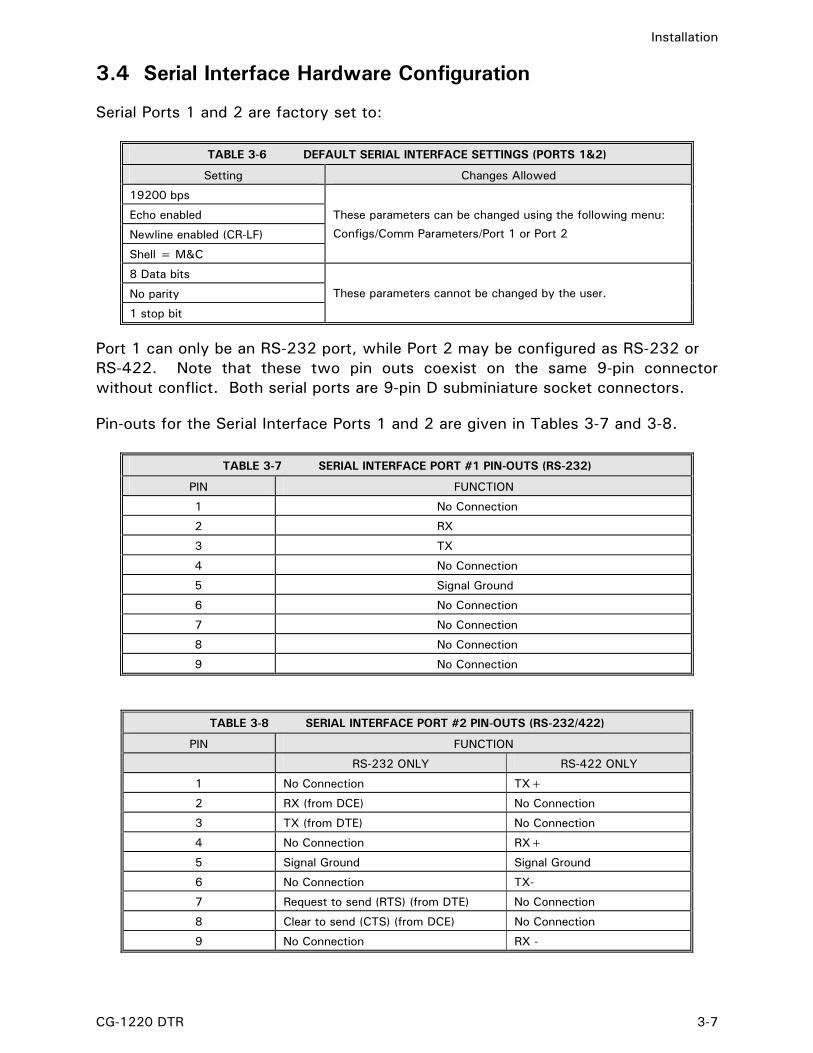
3.4 Serial Interface Hardware Configuration Serial Ports 1 and 2 are factory set to:
TABLE 3-6 DEFAULT SERIAL INTERFACE SETTINGS (PORTS 1&2)
Setting Changes Allowed
19200 bps
Echo enabled
Newline enabled (CR-LF)
Shell = M&C
These parameters can be changed using the following menu:
Configs/Comm Parameters/Port 1 or Port 2
8 Data bits
No parity
1 stop bit
These parameters cannot be changed by the user.
Port 1 can only be an RS-232 port, while Port 2 may be configured as RS-232 or RS-422. Note that these two pin outs coexist on the same 9-pin connector without conflict. Both serial ports are 9-pin D subminiature socket connectors. Pin-outs for the Serial Interface Ports 1 and 2 are given in Tables 3-7 and 3-8.
TABLE 3-7 SERIAL INTERFACE PORT #1 PIN-OUTS (RS-232)
PIN FUNCTION
1 No Connection
2 RX
3 TX
4 No Connection
5 Signal Ground
6 No Connection
7 No Connection
8 No Connection
9 No Connection
TABLE 3-8 SERIAL INTERFACE PORT #2 PIN-OUTS (RS-232/422)
PIN FUNCTION
RS-232 ONLY RS-422 ONLY
1 No Connection TX+
2 RX (from DCE) No Connection
3 TX (from DTE) No Connection
4 No Connection RX+
5 Signal Ground Signal Ground
6 No Connection TX-
7 Request to send (RTS) (from DTE) No Connection
8 Clear to send (CTS) (from DCE) No Connection
9 No Connection RX -

Installation
3-8 CG-1220 DTR
Serial Port 3 is factory set to:
TABLE 3-9 DEFAULT SERIAL INTERFACE SETTINGS (PORT 3)
Setting Changes Allowed
19200 bps
Shell = M&C
Master Address = 0
Slave Address = 1
Address Offset = 48
These parameters can be changed using the following menu:
Configs/Comm Parameters/Port 3
8 Data bits
No parity These parameters cannot be changed by the user.
1 stop bit
Port 3 is a half-duplex RS-485 port and is a 9-pin D subminiature socket connector. Pin-outs for the Serial Interface Port 3 are given in Table 3-10.
TABLE 3-10 SERIAL INTERFACE PORT #3 PIN-OUTS (RS-485)
PIN FUNCTION
1 Data + (Half-Duplex)
2 No Connection
3 No Connection
4 No Connection
5 No Connection
6 Data - (Half-Duplex)
7 Cable Shield
8 No Connection
9 No Connection

Installation
CG-1220 DTR 3-9
3.5 Initial Setup and Power-up Detailed operating instructions for the DTR are provided in Section 4.0 of this manual. The operator should become familiar with the general operating procedures before continuing.
NOTE: Prior to powering the DTR, observe the incoming beacon signal using a spectrum analyzer to ensure proper level (-110 dBm to -40 dBm) and sufficient Carrier to Noise ratio (C/No) (35 dbHz minimum). Also, make note of the beacon signal frequency. Then connect the RF input(s) to the appropriate N-Type connectors and proceed with the following steps.
1. Set the DTR rear panel POWER switch to ON. 2. Verify that the 240x64-pixel graphical receiver status display shows a normal
operational mode. A default frequency and signal acquisition status should be displayed.
Figure 3-2 Typical Operational Display
3. Set POL SELECT item to the desired input (on multiple port configurations). 4. If necessary, select FREQUENCY and enter the desired frequency by either
rotating the spin knob, or by using the numeric keys to enter the appropriate frequency.
5. Once signal acquisition occurs, verify that no faults are indicated. 6. For troubleshooting assistance, navigate to STATUS\TROUBLE-SHOOT. This
menu describes what some of the possible error messages mean and how to fix them.

Installation
3-10 CG-1220 DTR
3.5.1 Analog Voltage Output (DAC) Setup 1. Tune frequency to obtain desired signal at maximum power level. 2. Use DAC SETUP menu to establish VOLTAGE RANGE, MINIMUM REF POWER
LEVEL, and SLOPE.
DAC1 provides an analog DC voltage, proportional to signal level, on pins 1 and 14 (+OUT, -OUT) of I/O Interface #1 on the back panel. A. The DC VOLTAGE RANGE of the Digital to Analog Converter (DAC) is set to
the default range of (0 to +10V). For Special uses, the voltage range can alternatively be set to (-10 to +10V), or (-5 to+5V).
B. The SLOPE defaults to 0.3V/dB. SLOPE controls the rate of change of the DC
output voltage with respect to a 1 dB change in signal power level.
C. The MINIMUM REF POWER LEVEL establishes the power level corresponding to the minimum DAC voltage. The default is –90 dBm which emulates VertexRSI “TRL” operation.
3. Check DAC1 output voltage (displayed on the front panel) and adjust MINIMUM
REF POWER LEVEL to obtain 8 VDC. Note: If both DAC1 and DAC2 are enabled, the front panel display will report DAC1 voltage real-time (not at specified DAC1 update rate). If DAC1 is disabled and DAC2 is enabled, front display will report DAC2 voltage real-time; label will change to DAC2=. If DAC1 is enabled and DAC2 is disabled, front display will report DAC1 voltage real-time. If DAC1 is disabled and DAC2 is disabled, front display will not report anything (blank field). 3.5.2 Setting up Beacons for 7134 Remote Control This brief summary outlines steps necessary to establish beacons which can be accessed via remote control from VertexRSI 7134 ACUs. 1. Set necessary parameters such as FREQUENCY, SLOPE, etc. See Section
4.2.5.4, BEACON SETUP for a complete list of beacon parameters. 2. Execute the STORE BEACON 1-4 menu at CONFIGS\BEACON-SETUP\STORE-
BEACONS. These current settings will be stored in the respective beacon (BEACON 1-4).
3. Test by recalling BEACON 1-4. 4. The connection to the 7134 is via the I/O Interface #1. (Refer to Table 3-2)
5. To allow the 7134 ACU to select beacons, set CONFIGS\REMOTE CONTROL to
I/O Interface #1.

Installation
CG-1220 DTR 3-11
6. On the front panel, press SHIFT-REMOTE to enter REMOTE mode. 7. Test by selecting BEACON 1-4 at the 7134 ACU. 3.5.3 Controlling DTR with 72XX ACUs via Serial port The information below briefly describes the connections for controlling a DTR from a VertexRSI 7200-series ACU. 1. Using the connections matrix in Table 3-11 below, decide on a valid RS-232 or
RS-422 communications standard connection between the DTR and 7200. An invalid connection is marked by an “X” and cannot be used. Note that DTR Port 2 can be used as either a RS-232 or RS-422 port, and that DTR Port 3 is RS-485 only and cannot be used with a 7200 ACU.
TABLE 3-11 DTR TO 7200 ACU SERIAL CONNECTIONS MATRIX
7200 ACU PORT J14(1) J15(2) J16(3) J17(4) J18(5) J19(6) J20(7)
1 RS232 RS232 X X X X X 2 RS232 RS232 RS422 RS422 RS422 RS422 RS422
DTR
3 X X X X X X X
2. Using Table 3-12 a, b, or c below, make the correct physical connections per the
connector and port standard decision made in step 1.
TABLE 3-12a RS-232 CONNECTIONS TO 7200 ACU
DTR PORT 1 OR 2 (DE-9) ACU PORT J14 OR J15 (DB-25) 2 – RX 2 – TX 3 – TX 3 – RX 5 – GND 7 – GND
TABLE 3-12b RS-422 CONNECTIONS TO 7200 ACU
DTR PORT 2 (DE-9) ACU PORT J16 OR J17 (DB-25) 1 – TX+ 22 – RX+ 4 – RX+ 19 – TX+ 5 – GND 1 – GND 6 – TX- 9 – RX- 9 – RX- 6 – TX-
TABLE 3-12c RS-422 CONNECTIONS TO 7200 ACU
DTR PORT 2 (DE-9) ACU PORT J18-J20 (DE-9) 1 – TX+ 4 – RX+ 4 – RX+ 1 – TX+ 5 – GND 5 – GND 6 – TX- 9 – RX- 9 – RX- 6 – TX-
Installation
3-12 CG-1220 DTR
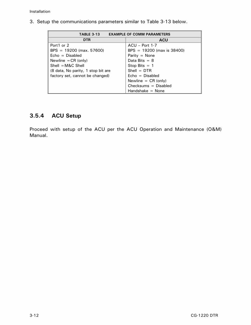
3. Setup the communications parameters similar to Table 3-13 below.
TABLE 3-13 EXAMPLE OF COMM PARAMETERS
DTR ACU Port1 or 2 BPS = 19200 (max. 57600) Echo = Disabled Newline =CR (only) Shell =M&C Shell (8 data, No parity, 1 stop bit are factory set, cannot be changed)
ACU – Port 1-7 BPS = 19200 (max is 38400) Parity = None Data Bits = 8 Stop Bits = 1 Shell = DTR Echo = Disabled Newline = CR (only) Checksums = Disabled Handshake = None
3.5.4 ACU Setup Proceed with setup of the ACU per the ACU Operation and Maintenance (O&M) Manual.

Operation
CG-1220 DTR 4-1
4.0 OPERATION This section of the manual explains in detail how to operate the DTR. Table 4-1 describes the function of each control and indicator shown in Figure 4-1.
Figure 4-1 DTR Controls and Indicators
TABLE 4-1 CONTROLS AND INDICATORS
CONTROL OR INDICATOR FUNCTION
1. Receiver Status Display
The Receiver Status Display is a 240x64-pixel graphical display that indicates the selected frequency, power level, operational mode, and other user-selectable features such as the Spectral Display (detailed in Section 4.2.4).
2. Soft Keys The Soft-Key interface lends flexibility to the unit and allows the user to select and navigate menus. The function of each key is defined by text displayed on the screen immediately to the left of each key and will change with context.
The dedicated Navigation Keys allow the user to move quickly between menus.
HELP
The HELP key on the front panel is used to assist the user by describing the highlighted menu item. When pressed, a help screen is displayed and assists the user by describing or clarifying the highlighted item. If pressed when a menu item is not highlighted, a summary of the help screen is displayed.
PREV
The PREV key is used to back out of menus. Pushing it after a menu item has been selected cancels the input.
PAGE
An ↓ or ↑, appearing at the bottom-right or top-right of the screen, indicates that more menu choices are available. Use PAGE to show these additional choices.
SHIFT
3. Navigation Keys
The SHIFT key is a “Dual Function” key. When used in conjunction with the other navigational keys, it performs alternate functions. SHIFT+PAGE reverses the PAGE function. SHIFT+HELP toggles LOCAL/REMOTE Mode.
4. Status Indicators The Status Indicators indicate 1) LOCAL/REMOTE mode; 2) Failure in critical internal sub-systems (downconverter chain Phase-Locked Loops (PLLs) and loss of phase lock in receiver); 3) Power.
5. Numerical Keypad A numeric keypad allows the user to enter numeric entries and control parameters.
6. Spin Knob The Spin Knob is used to provide real-time frequency tuning and to edit other system parameters. It also allows the user to cycle through menus and choices.
7. IF Monitor The IF Monitor taps the frequency being input into the DSP board. The BNC Connector on the front panel is a buffered 70 MHz Intermediate Frequency (IF) monitor port. The IF monitor port has a 50-Ohm output impedance.

Operation
4-2 CG-1220 DTR
The Receiver Status Display, shown below in Figure 4-2, displays the frequency, signal source and levels, faults, etc. along with the Main Menu of the DTR. Table 4-2 describes each display feature.
Figure 4-2 Receiver Status Display Screen
TABLE 4-2 RECEIVER STATUS DISPLAY
CONTROL OR INDICATOR FUNCTION
1. Power Meter Graphical representation of input signal level in dBm. Range automatically adjusts relative to power level.
2. Signal Level Input Signal level in dBm
3. Frequency Frequency of the receiver in MHz
4. Carrier to Noise Ratio Calculated C/No of tracking signal
5. Voltage Output Current analog voltage output
6. Fault Display Displays faults and alarm conditions
7. Menu Used to support the various system interfaces and control system parameters.

Operation
CG-1220 DTR 4-3
4.1 Understanding the DTR Menu Structure The MAIN MENU on the Receiver Status Display contains items which support the various system interfaces and control system parameters. An arrow (↓ or ↑) at the top-right or bottom-right of the menu display indicates that additional menu items are available. These menu items can be accessed by pressing [PAGE]. The Navigation keys [PREV], [PAGE] and [SHIFT] allow the user to move within menu items (see Table 4-1). Each item of the MAIN MENU will be discussed in the following paragraphs. For a complete visual representation of the menu hierarchy, refer to Appendix B, DTR Menu Tree.
4.1.1 Selecting Menu Items The Soft Keys and Navigation keys are the primary function keys used in making all menu choices. Menu items, displayed near the right side of the Display, are selected by pressing the Soft Key immediately to the right of the menu item (See Figure 4-1). The DTR’s flexible interface also lets the user cycle through menus items with the Spin Knob. Once the desired menu is highlighted, press the [ENTER] key.
4.1.2 What Happens When a Menu is Selected… Selecting a menu does one of three things depending on its context:
4.1.2.1 Selects a Submenu The most basic outcome of selecting a menu item is a resulting submenu. Each submenu item may contain additional submenus. Generally, no menu will have more than 8 items.
4.1.2.2 Opens an Editor Screen The [FREQUENCY] menu, for example, opens an editor screen where the user inputs a value. There are no additional submenus below an editor screen. The user can enter data in a number of ways within an editor. The Soft Key functions change to assist the user. In addition, the keypad can be used to directly enter data. Finally, the Spin Knob also may be used. For items that require numeric input, acceptable ranges of values will appear on the screen. If an out-of-range value is entered, the system will reject the value and the value of the parameter will remain as it was before it was edited. The [ENTER] key on the keypad should be pressed after the desired value has been input. The [PREV] key will “cancel” any input leaving the former value intact. 4.1.2.3 Executes an Action A menu such as [ACKNOWLEDGE FAULTS] does not have submenus and does not open an editor. Instead it performs an action and maintains the current menu screen.

Operation
4-4 CG-1220 DTR
4.2 Main Menu Items The menus used to support the system interfaces and control system parameters follow. See Appendix B for a complete Menu Tree. The following are considered to be the MAIN MENU items:
• 1 - FREQUENCY • 2 - INPUT ATTEN • 3 - POL SELECT • 4 - STATUS • 5 - CONFIGS • 6 - ACKNOWLEDGE FAULTS • 7 - TESTS
4.2.1 FREQUENCY The [FREQUENCY] menu allows the user to edit the receiver tuning frequency in 1kHz increments. The valid frequency range depends on the DTR’s block down converter configuration. While the receiver is under LOCAL control the editing input source should be either the keypad interface or the spin-knob. When the receiver is in REMOTE control (controlled by the data link that is configured as the port in control) frequency editing is initiated and executed using ASCII M&C commands via the data link.
4.2.2 INPUT ATTEN [INPUT ATTEN] controls an internal attenuator inside the RF front end. The attenuator is located after the first amplifier but before the first stage mixer. The default is 0 dB, but the INPUT ATTEN function may be used to compensate for overload signal conditions. When using the attenuator, the front panel signal level reading will automatically compensate so a correct dBm reading is obtained. The range is 0 to 30 dB in 2 dB steps. Use the scroll knob to scroll through the available values, 0, 2, 4, …, 30. You must press the ENTER button after a selection is made to use the new value.
4.2.3 POL SELECT [POL SELECT] allows the user to select which POL input is the active port for tracking. The numeral “1” or “2” will appear next to the POL SELECT menu in the main menu, indicating which POL input is active. This setting is used to control an RF switch internal to the DTR, and may also be used to control an external switch using I/O Interface #1 on the back panel. GPIO 6 and 7 become active based on the POL SELECT setting. Pins 11,24 represent the POL 1 state and pins 12,25 represent the POL 2 state (see Table 3-2). Notice that if multiple POL switches are configured (i.e. in a tri-band system) changing POL will affect all bands (all POL switches are “ganged” together).

Operation
CG-1220 DTR 4-5
4.2.3.1 POL SELECT (Four Port Option Only) [POL SELECT] allows the user to select which POL input is the active port for tracking. The numeral “1”, “2”, “3”, or “4” will appear next to the POL SELECT menu in the main menu, indicating which POL input is active. This setting is used to control an RF switch internal to the DTR, and may also be used to control an external switch using I/O Interface #1 on the back panel. GPIO 4, 5, 6 and 7 become active based on the POL SELECT setting. Pins 11,24 represent the POL 1 state, pins 12,25 represent the POL 2 state, pins 9,22 represent the POL 3 state, and pins 10,23 represent the POL 4 state (see Table 3-2). 4.2.4 STATUS MENU The Status menu [STATUS] allows the user to view various operational parameters, operating voltages, and settings in a single display window. This information can be useful in diagnosing system problems. The [STATUS] menu contains the following submenus.
• SPECTRAL DISPLAY – This feature allows the user to view real time amplitude vs. frequency data in a graphical manner similar to a spectrum analyzer. Use the Spin Knob to adjust frequency. Soft keys A/B change step size. Soft keys C/D change vertical scale. Press [PREV] to exit.
Figure 4-3 Spectral Display
• SPU SERIAL LINK STATS – This screen displays SPU RS422 serial link statistics separately
for the MCU and DSP. Timeouts are displayed when the CPU did not get a response within 100ms. Errors are logged when an unexpected response did not match internal protocol. The percentage of errors plus timeouts versus the total number of commands is displayed. Linklosses displays the number of failures to establish communication with the MCU or DSP processors. Finally, the total number of commands sent is displayed.
• I/O STATUS – Current I/O status information obtained from the I/O card is displayed. This information is intended for diagnostic purposes. Given data format x(y), all x are hex and all y are human-interpretable synonyms of x. x is the internal configuration value useful to VertexRSI technical support (it is subject to change without notice). y is loosely the selected band, but more specifically: (-) if x is undefined (more than one or none), ( ) if x is none; see the specific field description for more details.

Operation
4-6 CG-1220 DTR
- The INTF#1 and the INTF#2 fields provide information regarding the input and output
states of the I/O INTERFACE #1 and I/O INTERFACE #2 connectors on the back panel. - FAULTS is a 4-bit mask where bit 0 is the fault indicator of the first BDC, bit 1 is of the
second, etc. A zero bit means the BDC is present and powered off (or malfunctioning). "ok" or "BAD" is display, the latter if the BDC for the current band is malfunctioning or not powered up.
- The BDC fields are internal bit settings that the I/O card uses to set the correct BDC for
the selected band.
o BDC POWER IN - y is the number of the BDC whose power is on.
o BDC SELECTED - x bits are active low (e.g. 0x7=~0x8,... 0xE=~1). y is the number of the BDC whose RF output is selected. Note: standard product DTR's do not use SPDT switches with indicators, therefore these always show the status bits set (-).
o BDC POWER OUT - x bits are active high and specify the BDC to turn on and the others to turn off, bit 7 for BDC 1 on, bit 6 for BDC 1 off, 5 for BDC 2 on, etc. y is the number of the BDC whose power was turned on.
o BDC SELECT - x bits are active high, bit 3 set for position 1, 2 for 2, etc. y is the number of the BDC whose RF output was selected.
- The SPDTX4 fields are internal bit settings that the I/O card uses to set the correct RF
switch settings.
o SPDTX4 SW IN - x bit 3 for SW1, 2 for 2, etc. y is the configuration that the SPDT switches (one to four) are in. The first two characters together are both SW1 and SW2, used for RF input selection, which indicate whether the switches are set to their "Lo"w or "Hi"gh band. The next two are SW3 and SW4, respectively, used for POL SELECTion, which indicate whether the switch is in position 1 or 2. Note: standard product DTR's do not use SPDT switches with indicators, therefore these always show the status bits set (-).
o SPDTX4 SW OUT - x bits are active high and specify the RF switch position to set
to 1 or 2, bit 7 set for SW1 position 2, 6 for SW1 position 1, 5 for SW2 position 2, etc. y is the configuration that the SPDT switches (one to four) were set to. The first two characters together are both SW1 and SW2, used for RF input selection, which indicate whether the switches were set to their "Lo"w or "Hi"gh band; they are switched simultaneously leaving the BDC SELECT switch to differentiate between them. The next two are SW3 and SW4, respectively, used for POL SELECTion, which indicate whether the switch was set to position 1 or 2.
- The PLL VOLTAGES are self-explanatory. - The TEMPERATURES fields (in degrees Fahrenheit) are for the L-Band Front End and
Signal Processing Unit.
*Regarding BDC SELECTED and SPDTX4 SW IN, standard product DTR's do not use SPDT switches with indicators, therefore these always show the status bits set (-).

Operation
CG-1220 DTR 4-7
• FIFO STATUS – Displays first-in-first-out (FIFO) data statistics from the DSP/CPU link. The
following are counted: Status Frames, Signal Frames, Spectrum Frames, Monopulse Frames, Missing Monopulse Frames, Bad Footers, Unknown Frames and Total Frames. The counts and percents of the given types identify the total number and proportion of frames received since power-up. FPS is frames per second and MS/Frame is milliseconds per frame.
− Status frames contain signal for the front panel and M&C interface. − Spectrum frames contain data for the SPECTRAL DISPLAY. − Monopulse frames, either on time or late, contain signal and error vector data for
monopulse mode. Monopulse used is the number of frames transmitted out via the M&C monopulse interface. The other ones that are not needed are discarded. "Late monopulse" increments each time monopulse data is requested by or due to be sent to the ACU but a new reading is not yet available. This may increment regularly in a high-performance ACU and a narrow digital filter in the DTR, or when the ACU requests each transmission (RATE = -1). On-time monopulse frames are those that arrive before they are needed.
− Bad footers are when a frame header is intact but the footer (or intervening data) has been corrupted.
− Unknown frames are when frames are out of synchronization or a frame header has been corrupted.
• MESSAGE LOG displays the most recent events recorded in the system message buffer.
Pressing [PAGE] and [SHIFT]+[PAGE] or spinning the knob scrolls the list; [PREV] exits.
• DISPLAY VERSION displays the current firmware version and configuration information for the DTR.
• CPU TASKS displays current CPU tasks, including task number, name, shell type and
activity
• TROUBLESHOOT is a diagnostic tool to provide online assistance on the current faults.
4.2.5 CONFIGURATION MENU The Configuration menu [CONFIGS] provides access to system parameters and settings. The [CONFIGS] menu provides the following:
• COMM PARAMETERS • RECEIVER OPERATION • CONVERSION BANDS • BEACON SETUP (Only in Non-Monopulse units) • MONOPULSE (ONLY in Monopulse units) • SYSTEM MEMORY • INTERFACE OPTIONS
4.2.5.1 COMM PARAMETERS
• REMOTE CONTROL - This editor selects which port on the back panel is in control when the DTR is in REMOTE mode. For remote M&C communications, select Port1 or 2, which support serial protocols.

Operation
4-8 CG-1220 DTR
• PORT 1, PORT 2 – These two menus configure the port for M&C communications. Port 1 is RS-232 only, while Port 2 allows RS-232 or RS-422 connections. See Table 3-6 for factory set data parameters for these ports. The following submenus are configurable for M&C communications: − BPS (BAUD) – The transfer rate of Port 1 can be set from 1200 to 57,600 BPS. The
transfer rate of Port 2 can be set from 1200 to 115,200 BPS.
− NEWLINE – When enabled, a carriage return line-feed (CR-LF) is sent at the end of the command line. When disabled, only a carriage return (CR) is sent.
− ECHO returns the received character to the port.
− SHELL determines the communications protocol used on this serial port. DISABLED
disables the serial port. M&C SHELL provides Monitor and Control protocol support including status polling and system configuration capability. 72xx M&C Shell provides TRL Monitor and Control protocol support for status polling and system configuration by a 72xx ACU with version 2 firmware. An ACU remote port set to DTR and a DTR set to 72xx M&C SHELL will NOT communicate. MESSAGE PRINTER is a diagnostic tool which may be used to record system events when connected to a terminal program or a serial printer. TBT INTERFACE (Optional) supports serial control of VertexRSI Tracking Band Translator (TBT).
− RESET PORT resets the given port. The communication interface is reinitialized and the
shell (if any) that was running on it is restarted.
• PORT 3 – This menu configures the RS-485 Port 3 for M&C communications. See Table 3-9 for factory set data parameters for this port. The following submenus are configurable for M&C communications: − BPS (BAUD) – The transfer rate of Port 3 can be set from 1200 to 115,200 BPS. − SHELL determines the communications protocol used on this serial port. DISABLED
disables the serial port. M&C SHELL provides Monitor and Control protocol support including status polling and system configuration capability.
− MASTER ADDRESS is the address of the master (controlling) device on the multi-drop
RS-485 bus. There are a maximum of 32 addresses, ranging from 0 to 31. On the bus, the actual ASCII value used for addressing is the address assigned here plus the value of the parameter ADDRESS OFFSET.
− SLAVE ADDRESS is the address of this unit (a slave, controlled) on the multi-drop RS-
485 bus. There are a maximum of 32 addresses, ranging from 0 to 31. On the bus, the actual ASCII value used for addressing is the address assigned here plus the value of the parameter ADDRESS OFFSET.
− ADDRESS OFFSET is the offset added to the multi-drop bus address of a device to
determine the ASCII value needed to be used on the bus.
Example: ADDRESS-OFFSET is 48 (ASCII for '0') MASTER-ADDRESS is 0 SLAVE-ADDRESS is 1 In the above example, the ASCII value on the RS-485 multi-drop bus would be 48 (ASCII for '0') for the master, and 49 (ASCII for '1') for the slave.
− RESET PORT resets the given port. The communication interface is reinitialized and the
shell (if any) that was running on it is restarted.

Operation
CG-1220 DTR 4-9
4.2.5.2 RECEIVER OPERATION
The RECEIVER OPERATION configures how the Signal Processing Unit (SPU) processes input signals.
• FILTERS controls the bandwidth of the band-pass filter, centered around the receiver tuning frequency. A signal is detectable if it is visible on the spectral display (MAIN\STATUS\SPECTRAL DISPLAY). A spectrum analyzer attached to the IF Monitor port may be used to view the filter band. Filters 1 MHz and narrower are centered at 70 MHz. Filters wider than 1 MHz are centered at 72 MHz, except 16 MHz. For the 16 MHz filter, the tuning frequency is translated to 71 MHz; filter coverage is 9 MHz below to 7 MHz above. The 16 MHz filter has a 1.5 MHz notch 7 MHz below the tuning frequency. To use this filter, the NCO OFFSET should be zero (MAIN\CONFIGS\SYSTEM MEMORY\FACTORY CALIBRATION\NCO OFFSET). In standard configurations choose from: 16 kHz, 32 kHz, 62.5 kHz, 125 kHz, or 250 kHz. In addition, wide-band units provide these additional filters: 500 kHz, 1 MHz, 2 MHz, 4 MHz, 8 MHz, 12 MHz, and 16 MHz.
• ANALOG OUTPUTS - The ANALOG OUTPUTS menu controls the Digital to Analog Converter (DAC) and contains the following items:
− DAC1 and DAC2 SETUPS – DAC1 provides an analog DC voltage proportional to signal level on pins 1 and 14 (+OUT, -OUT) of I/O Interface #1 on the back panel. DAC2 provides an analog DC voltage proportional to signal level on pins 3 and 16 (+AUX, -AUX) of I/O Interface #1 on the back panel. See Section 3.5.1 for DAC setup information. Both DAC1 and DAC2 SETUPS have the following submenus:
− VOLTAGE RANGE selects the DC voltage range of the DAC. This value is used to
represent the signal level as a tracking voltage
− MINIMUM REFERENCE POWER LEVEL sets the minimum input power level reference which corresponds to minimum DAC voltage output.
− SLOPE controls the rate of change of the DC output with respect to a 1 dB change
in signal power level. Select a value from -1.000 to 1.000 V/dB.
− OUTPUT enables or disables the respective DAC output, DAC1 or DAC2.
− UPDATE RATE, in milliseconds, is used by the DSP to send the current signal level to both DAC1 and DAC2 outputs. Notice that the VOLTAGE RANGE, MINIMUM REFERENCE POWER LEVEL, and SLOPE may be independently set up. However, the UPDATE RATE applies to both DAC outputs.
− ATTENUATION controls the lower end of the Digital to Analog Converter (DAC) voltage
output, in conjunction with the parameters in the DAC1 and DAC2 setups. The range is from 0 to 50 dB. Rotating the spin knob clockwise, for example, increases the apparent attenuation, resulting in a lower voltage level output; actual input power is not affected. NOTE: This parameter will affect both DAC1 and DAC2. Also, this parameter is not intended to compensate for signal overload conditions. If signal overload occurs, use parameter INPUT ATTEN from the MAIN MENU.
• FFT SAMPLE AVERAGING determines how new FFT data is combined with previous data. Increasing AVERAGING smoothes the spectral curve and increases the stability of the display. Decreasing AVERAGING improves the DTR response time.
• DETECTION (WIDEBAND OPTION ONLY) selects how the DTR will report signal power. FFT
SIGNAL is the default, used to track broad spectrum signals, using FFTs. FFT NOISE is a special mode used to track broad spectrum signals, using FFTs. RMS POWER will report a direct RMS power estimate, without using FFTs. RMS DENSITY will report direct RMS power density estimate, without using FFTs.

Operation
4-10 CG-1220 DTR
4.2.5.3 CONVERSION BANDS*
*Displays only in configurations with block down converters The [CONVERSION BANDS] menu describes the downconverter setup and has various submenus, depending on the number of bands in any particular model. Each BAND menu (1-4) has the following submenus:
• BDC GAIN is the measured gain in dB of the BDC/attenuator pair for this band. • OSCILLATOR FREQUENCY is the local oscillator frequency of the BDC for this band. • LOW FREQUENCY is the low-end frequency of the BDC that supports this band. • HIGH FREQUENCY is the high-end frequency of the BDC that supports this band. • LBAND-DEFAULTS sets BAND 1 parameters to L-Band defaults.
WARNING: Changing these values may cause the DTR to stop working. Only change these values when directed to do so by VertexRSI customer support personnel. 4.2.5.4 BEACON SETUP*
* Only available in Non-Monopulse units. A subset of DTR system parameters may be stored as BEACONS to provide parallel control via I/O Interface #1. This provides support of legacy VertexRSI interfaces, such as the 7134 ACU. See Section 3.5.2 for more information on setting up beacons with a 7134 ACU.
• STORE BEACONS – Executing each item in this menu will store current values of the following parameters as a BEACON state:
• FREQUENCY • SLOPE • POL-SELECT • VOLTAGE RANGE • ATTENUATION • MINIMUM POWER REFERENCE • FILTER LEVEL • INPUT ATTEN
Only DAC1 SLOPE, VOLTAGE RANGE, and MINIMUM POWER REFERENCE LEVEL are stored. Those parameters for DAC2 are not stored.
• RESTORE BEACONS – Executing each item in this menu will restore values previously stored as a BEACON state.

Operation
CG-1220 DTR 4-11
4.2.5.5 MONOPULSE* * Only available in Monopulse units. This MONOPULSE menu provides the ability to configure some aspects of monopulse mode and view others. Monopulse mode uses one of the serial ports to communicate with the VertexRSI 7200 series ACU via the M&C SHELL. Control and status of the monopulse RF signal processing assembly is provided via lines located on the general purpose I/O interfaces.
• MUTE controls the combination of signal and error channels in the monopulse hardware. Disable to include the error channel for monopulse operation. Enable to exclude the error channel for normal operation. NOTE: This can also be set by M&C commands in TRL-Emulation.
• MUTE-FAULT enables or disables the mute switch fault. This feature should be disabled for
monopulse plates which do not support mute switch feedback. Disabling the fault on systems that support mute switch failure detection is not recommended for normal operation. Feedback is provided via mute status lines on I/O interface 2.
• RATE is the minimum number of milliseconds between the monopulse data transmissions of
START. If the value is -1, new data is sent only after receiving a carriage return. NOTE: Also used by M&C in TRL-Emulation
• MODE sets the type of monopulse output of START, either two error vectors with sum for
normal operation or four phase levels for diagnostics. Remote control is required to start normal operation; loss of control stops automatically. All output is in hexadecimal:
0:VECTORS reply:
"[+|-]ddddd [+|-]eeeee -fffff" where d and e units are |dBm/10000| and f units are |dBm/1000| (range 0 to -262.143 dBm)
1:LEVELS reply:
"+dddddd +eeeeee +ffffff +gggggg" where units are |dBm/1000|
NOTE: Also set by M&C in TRL-Emulation
• START monopulse operation; to stop, use EXIT followed by a carriage return. It stops automatically if and when a fault is set. After stopping, in either case, the mute switch is enabled. NOTE: Only usable via the M&C

Operation
4-12 CG-1220 DTR
4.2.5.6 SYSTEM MEMORY The SYSTEM MEMORY menu contains functions related to the storage of system parameters in nonvolatile RAM (NVRAM).
• FACTORY CALIBRATION contains system parameters that are calibrated in factory and are NOT normally changed by the user. CHANGING THE PARAMETERS IN THIS MENU MAY DEGRADE THE PERFORMANCE OF THE DTR.
− SAMPLING FREQUENCY compensates for the oscillator's slight deviation from nominal
64 MHz. Entering the actual oscillator frequency to within 1Hz maximizes the receiver's performance. This calibration is done in the factory for each DTR before shipment; it should NOT be changed in most cases.
If it must be reconfigured, connect a cable from the 70 MHz IF monitor (on the front of the DTR) to a spectrum analyzer. Set up the spectrum analyzer as follows: 1) Set Auto Couple to ALL. 5) Center the frequency. 2) Set Frequency to 64 MHz. 6) Span down to 500 Hz. 3) Set Span to 5 KHz. 7) Record and enter the measured value. 4) Peak-search the signal.
− NCO OFFSET adjusts the frequency of the Numerically Controlled Oscillator (NCO) on
the SPU. − POWER LEVEL CALIBRATION adjusts the calibration value used to calculate the signal
power measurement reported by the DTR (shown on the front display in dBm). This parameter should NOT be modified under normal circumstances.
− MANUAL IF OVERRIDE allows the user to manually select the Intermediate Frequency
(IF) used by the L-band front end. The DTR normally selects the optimal IF; this menu provides flexibility for special cases.
− FREQUENCY #1-4 OVERRIDE allows user selection of up to four IF1s used by the L-
band front end for current frequency. IF1 specifies an approximate center for the digital filter within a 25 MHz analog filter centered at 836.5 MHz. “Automatic” is the default setting, but settings from 824.8 to 847.2 MHz are available.
− HARDWARE OPTIONS allows factory setup of special hardware configurations. These
options are typically set in the factory and should not be changed under normal circumstances.
− POL INPUTS allows user selection of STANDARD or 4 PORT.
• SET DATE AND TIME
The port used to set the date or time (local or remote) must be the one in control.
− SET DATE allows the current date to be set. In the M&C shell, the format is MMDDYYYY and al fields must be set.
− SET TIME allows the current time to be set. In the M&C shell, the format is HHMMSS
and all fields must be set. The time is in 24-hour format.

Operation
CG-1220 DTR 4-13
• RESTORE ROM DEFAULTS – WARNING: This will erase user and factory calibration
settings! Selecting YES and pressing ENTER restores all DTR parameters to factory ROM defaults. The DTR will reset.
• FORCE CLEAR FAULTS forces the system to clear all faults. Faults which are set
periodically will appear again. Also see ACKNOWLEDGE FAULTS below.
4.2.5.6 INTERFACE OPTIONS
• LCD CONTRAST adjusts the contrast of the LCD display. Choose a value between 0 (for least contrast) and 30 (for most contrast). The default value is 6.
• LOW LEVEL SIGNAL – This value, in dB, sets the trigger threshold for the LOW INPUT
SIGNAL fault. Regardless of this value, the LOW INPUT SIGNAL fault will still occur if input signal is undetectable. The default value is -120 dBm.
• LOW SIGNAL ALARM – LOW SIGNAL ALARM enables the LOW INPUT SIGNAL alarm,
allowing the fault to be reported. This is not useful for most applications and is disabled by default.
• HIGH TEMP LIMIT – This value, in degrees Fahrenheit, is used to trigger the TEMPERATURE
ALARM fault. The default value is 120° F.
4.2.6 ACKNOWLEDGE FAULTS Choosing [ACKNOWLEDGE FAULTS] clears current alarm conditions. The fault messages remain displayed on the screen, but no longer cause an alarm and the summary fault contact closure is no longer asserted by the faults. Also see FORCE CLEAR FAULTS.
Operation
4-14 CG-1220 DTR
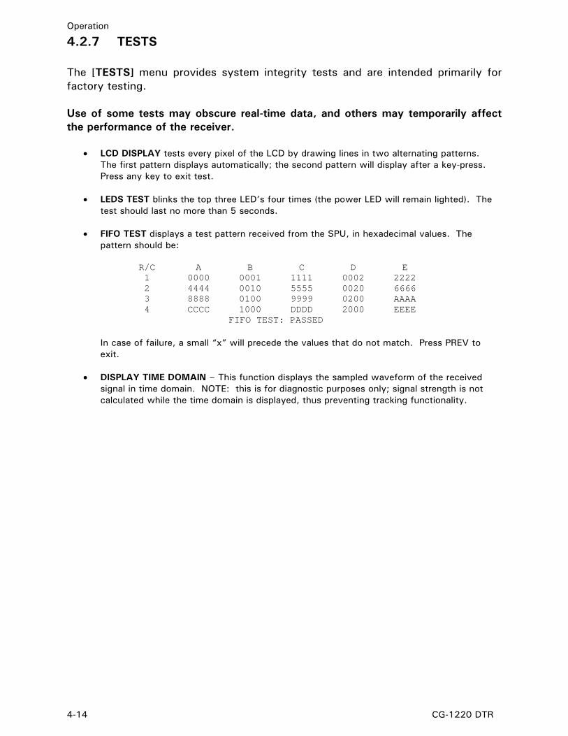
4.2.7 TESTS The [TESTS] menu provides system integrity tests and are intended primarily for factory testing. Use of some tests may obscure real-time data, and others may temporarily affect the performance of the receiver.
• LCD DISPLAY tests every pixel of the LCD by drawing lines in two alternating patterns. The first pattern displays automatically; the second pattern will display after a key-press. Press any key to exit test.
• LEDS TEST blinks the top three LED’s four times (the power LED will remain lighted). The
test should last no more than 5 seconds.
• FIFO TEST displays a test pattern received from the SPU, in hexadecimal values. The pattern should be:
R/C A B C D E 1 0000 0001 1111 0002 2222 2 4444 0010 5555 0020 6666 3 8888 0100 9999 0200 AAAA 4 CCCC 1000 DDDD 2000 EEEE
FIFO TEST: PASSED
In case of failure, a small “x” will precede the values that do not match. Press PREV to exit.
• DISPLAY TIME DOMAIN – This function displays the sampled waveform of the received
signal in time domain. NOTE: this is for diagnostic purposes only; signal strength is not calculated while the time domain is displayed, thus preventing tracking functionality.

Maintenance
CG-1220 DTR 5-1
5.0 MAINTENANCE
5.1 Inspection and Preventive Maintenance Scheduled maintenance should include the following: • Check the inside of the unit for excessive dust accumulation every 6 to 12
months. If excessive dust is found, remove it using a clean, dry (non-oiled) high-pressure air source.
• Check and clean the fan filter, accessible from back of unit, whenever dirty to
avoid overheating which may degrade system performance. • Replace batteries for non-volatile memory as required. The long life battery
ensures that user parameters are stored when the unit is powered off. If user parameters such as Frequency are not maintained (and return to defaults), the battery may need replacing.
5.2 System Spares Due to the complex nature of the DTR, there are VERY FEW user serviceable parts inside. Repairs must be made by qualified service technicians under the direction of VertexRSI Technical Support ONLY. Failure to follow this recommendation will void your warranty. The following spare parts can be ordered from VertexRSI.
TABLE 5-1 SPARE PARTS
P/N DESCRIPTION QTY PER SYS
CFU079 Fuse 1 Amp fuse 1
CSS091 Filter power entry module 85-265 VAC 1
BBA003 Battery coin 23mm DIA X 5.4mm 1
BFN010 Cooling Fan 1
CPS039 Power Supply 1
Additional parts such as printed circuit boards are NOT user-replaceable since they must be factory calibrated and matched with other components. In addition they must have the proper, compatible software version installed prior to installation in the unit.

Maintenance
5-2 CG-1220 DTR
THIS PAGE INTENTIONALLY LEFT BLANK

Engineering Drawings
CG-1220 DTR 6-1
6.0 ENGINEERING DRAWINGS
This section of the manual contains the following engineering drawing: 201807 Digital Tracking Receiver, Stock Level Drawing

Engineering Drawings
6-2 CG-1220 DTR
THIS PAGE INTENTIONALLY LEFT BLANK

Technical Support
CG-1220 DTR A-1
APPENDIX A - TECHNICAL SUPPORT If you have any questions or problems that are not addressed by the manual, there are several ways to contact our technical support team. Prior to contacting VertexRSI, please navigate to STATUS\DISPLAY VERSION and have the DTR’s Model, Serial, and corresponding software versions readily available. If the unit will not function, please consult the Model/Serial tag on the side of the unit for the proper unit identification information. 1. Phone us at (903) 295-1480. 2. Email us at [email protected]. 3. Make copies of the following Technical Inquiry form and fax us your questions at (903) 295-1479. 4. Contact us on our web site at www.vcsd.com.

Technical Support
A-2 CG-1220 DTR
Technical Inquiry FAX (903) 295-1479
CUSTOMER NAME:
SITE:
CONTACT:
PHONE:
EXT:
FAX:
EMAIL:
EQUIPMENT: (INCLUDE MODEL, NAME, AND SERIAL NUMBER OF ALL PERTINENT EQUIPMENT)
1. Model: 2. Model: 3. Model: 4. Model:
S/N: _________________ _________________ _________________ _________________
OTHER EQUIPMENT
TECHNICAL QUESTION/PROBLEM: VCSD RESPONSE: VCSD TROUBLESHOOTER
DATE
TIME
REF. NO.

Menu Tree
CG-1220 DTR B-1
APPENDIX B – MENU TREE This Appendix contains the menu tree for the DTR.

Menu Tree
B-2 CG-1220 DTR
MA
INM
ENU
APP
END
IX B
----
----
----
-D
IGIT
AL
TRA
CK
ING
REC
EIV
ERM
ENU
TREE
2. I
NPU
T A
TTEN
1.
FREQ
UEN
CY
5.
CO
NFI
GS
FR
EQ
UE
NC
Y =
949
.00
MH
z (R
ange
: 945
.000
to 2
055.
000)
1. S
PE
CTR
AL
DIS
PLA
Y2.
SP
U S
ER
IAL
LIN
K S
TATS
3. I/
O S
TATU
S4.
FIF
O S
TATU
S5.
ME
SSA
GE
LO
G6.
DIS
PLA
Y V
ER
SIO
N7.
CP
U T
AS
KS
8. T
RO
UB
LE S
HO
OT
7.
TEST
S
0. 1
6 K
Hz
2. 1
25 K
Hz
4. 3
2 KH
z1.
62.
5 K
Hz
3. 2
50 K
Hz
4.
STA
TUS
1. F
ILTE
RS
2. R
EC
EIV
ER
OP
ER
ATI
ON
2. A
NAL
OG
OU
TPU
TS
1. L
CD
DIS
PLA
Y
2.
LED
S T
EST
3. F
IFO
TES
T
4. F
AC
TOR
Y BU
RN
IN
3. U
PD
ATE
RA
TE
5. S
YS
TEM
ME
MO
RY
2. S
ET
DA
TE A
ND
TIM
E
6. A
CK
NO
WLE
DG
E
FA
ULT
S1.
SET
DA
TE2.
SET
TIM
E
0-3
0 dB
(2 d
B s
teps
)
3. F
FT S
AM
PLE
/AV
ER
AG
ING
AV
ER
AG
ING
RA
NG
E: 1
TO
200
0
4. B
EA
CO
N S
ETU
P
(N
OT
AV
AIL
AB
LE IN
MO
NO
PU
LSE
UN
ITS
)
1. S
TOR
E B
EAC
ON
S (1
- 4)
2. R
EST
OR
E B
EAC
ON
S (1
- 4)
1. C
OM
M P
AR
AM
ETE
RS
1. R
EM
OTE
CO
NTR
OL
BP
S (B
AU
D)
NE
WLI
NE
ECH
OS
HE
LLR
ES
ET
PO
RT
2. P
OR
T 1
(RS
-232
ON
LY)
3. P
OR
T 2
(R
S-23
2/R
S-42
2)
0. I/
O IN
TF #
1
1. P
OR
T 1
2. P
OR
T 2
3
.PO
RT
3
3. C
ON
VER
SIO
N B
AN
DS
(O
NLY
AV
AIL
AB
LE W
ITH
O
PTI
ON
AL
BD
Cs)
BA
ND
1B
AN
D 3
BA
ND
2B
AN
D 4
BDC
GA
IN
HIG
H F
RE
Q
LB
AN
D D
EFA
ULT
SO
SC
FR
EQ
L
OW
FR
EQ
(BA
ND
1 O
NLY
)
3. R
EST
OR
E R
OM
DE
FAU
LTS
4. F
OR
CE
CLE
AR
FA
ULT
S
6. IN
TER
FAC
E O
PTI
ON
S1.
LC
D C
ON
TRA
ST
2
. LO
W S
IGN
AL
LEV
EL
3
. LO
W S
IGN
AL
ALA
RM
4. H
IGH
TE
MP
-LIM
IT
3. P
OL
SELE
CT
1. 1
or 2
(D
EPE
ND
ING
ON
2. 1
- 4
S
ETT
ING
IN P
OL
IN
PU
TS)
4. P
OR
T 3
(RS
-485
)
1. S
AMP
LIN
G F
RE
QU
EN
CY
2. N
CO
OFF
SE
TR
AN
GE
: -60
00.0
00 T
O 9
9999
.999
RA
NG
E: 6
3990
.000
TO
640
10.0
0
3. P
OW
ER
LE
VE
L C
ALIB
RAT
ION
4. M
AN
UA
L IF
OV
ER
RID
E
1. F
REQ
#1
IF O
VE
RR
IDE
2. F
REQ
#2
IF O
VE
RR
IDE
3. F
REQ
#3
IF O
VE
RR
IDE
4. F
REQ
#4
IF O
VE
RR
IDE
1. D
AC
1 S
ETU
P1.
VO
LTA
GE
RAN
GE
2. M
IN R
EF P
OW
ER
LV
L3.
SLO
PE
4. O
UTP
UT
2. D
AC
2 S
ETU
P
1. F
AC
TOR
Y C
ALI
BR
ATI
ON
5. H
AR
DW
AR
E O
PTI
ON
S
BP
S (B
AU
D)
SH
ELL
MA
STE
R A
DD
RE
SS
SLA
VE A
DD
RE
SS
AD
DR
ES
S O
FFSE
TR
ES
ET
PO
RT
PO
L IN
PUTS
0 - S
TAN
DA
RD
1- 4
PO
RTS
4. D
ETE
CTI
ON
(WID
EBA
ND
O
PTI
ON
ON
LY)
4. A
TTE
NU
ATI
ON
W
IDE
BA
ND
OP
TIO
NS
0. 1
6 K
Hz
6. 1
MH
z1.
32
KH
z7.
2 M
Hz
2. 6
2.5
KH
z8.
4 M
Hz
3. 1
25 K
Hz
9. 8
MH
z4.
250
KH
z10
. 12
MH
z5.
500
KH
z 1
1. 1
6 M
Hz
OR
3. M
ON
OP
ULS
E
(O
NLY
AV
AIL
AB
LE IN
M
ON
PU
LSE
UN
ITS
)3.
RA
TE (-
1 to
100
00)
1. M
UTE
(0-D
isab
led;
1-E
nabl
ed)
2. M
UTE
-FAU
LT (0
-Dis
.; 1-
En.
)
4. M
OD
E (0
-Vec
tors
; 1-L
evel
s)
5. S
TAR
T

Remote M&C Protocol
CG-1220 DTR C-1
APPENDIX C – REMOTE M&C PROTOCOL This Appendix contains the remote M&C protocol for the DTR.

Remote M&C Protocol
C-2 CG-1220 DTR
THIS PAGE INTENTIONALLY LEFT BLANK

CG-6073
REV N APRIL 2006
REMOTE M&C PROTOCOL FOR THE
DIGITAL TRACKING RECEIVER
1915 Harrison Road Longview, Texas 75604
EXPORT CONTROL WARNING - Do not disclose this document or its contents to non-U.S. Citizens, or transmit this document or its contents outside the United States without the written permission of Vertex Communications Corporation and required U.S. Government approvals.

Appendix C– DTR Remote M&C Protocol CG-6073 (Rev M, Feb, 2006)
ii
Revision History Rev. N M. Neely 4-25-06 G. Branch 4-25-06 6629 Rev. M M. Neely 2-06-06 G. Branch 2-06-06 6456 Rev. L M. Neely 3-24-05 G. Branch 3-24-05 5718 Rev. K M. Neely 10-18-04 G. Branch 10-18-04 5469 Rev. J M. Neely 7-21-04 G. Branch 7-21-04 5355 Rev. H M. Neely 10-10-03 G. Branch 10-10-03 4518 Rev. G M. Neely 10-15-02 C. Bonner 10-18-02 4306 Rev. F M. Neely 6-14-01 D. Bulgrien 6-14-01 2624
Rev. No/change Revised By Date Approved By Date ECO#

Appendix C– DTR Remote M&C Protocol CG-6073 (Rev M, Feb, 2006)
3
TABLE OF CONTENTS
1.0 INTRODUCTION...................................................................5
1.1 Syntax Diagrams ........................................................................5
2.0 OVERVIEW..........................................................................6
3.0 GENERAL PROTOCOL...........................................................7
3.1 Range Details.............................................................................8
3.2 Error Messages ..........................................................................8
3.3 Status Requests .........................................................................9
4.0 DTR MENU TREE WITH MONITOR & CONTROL COMMANDS.. 10
5.0 MONITOR AND CONTROL COMMANDS ............................... 13
5.1 Keyword Commands................................................................. 50
6.0 RS-485 PROTOCOL FOR DTR MULTI-DROP BUS.................... 61
7.0 TRL EMULATION MODE...................................................... 65

Appendix C– DTR Remote M&C Protocol CG-6073 (Rev M, Feb, 2006)
4
THIS PAGE INTENTIONALLY LEFT BLANK

Appendix C– DTR Remote M&C Protocol CG-6073 (Rev M, Feb, 2006)
5
APPENDIX C DTR REMOTE MONITOR AND CONTROL
1.0 INTRODUCTION
This appendix contains the Digital Tracking Receiver (DTR) Remote Monitor and Control (M&C) protocol applicable to version 1.19.08 and higher of the DTR firmware. The M&C interface is provided to assist in the setup of remote communications with the DTR. The remote port communication parameters (bps, echo, newline) may be configured at the front panel of the DTR visual interface for the desired port. If you are unsure about your system configuration or cannot find the necessary information in this manual, please consult your VertexRSI representative.
1.1 Syntax Diagrams This section discusses syntax diagrams used in this document. 1. | Choices or optional data are shown inside brackets and separated by
the pipe “|” sign. 2. Text surrounded by curly brackets indicates a choice. The following
command example indicates that you can enter either a or b: command a | b 3. [ ] Square brackets indicate optional data. The following command
example indicates that argument_2 is optional: command argument1 [argument2] 4. < > Angle brackets indicate a single replaceable token. The following
command example indicates that you must specify one name and one value separated by a colon with no intervening spaces:
command <identifier name>:<identifier value> 5. … Horizontal ellipses show repetition of the preceding item(s). The
following command example indicates you can optionally specify more than one number: command number [...]
6. .. Indicates a range of argument values.

Appendix C– DTR Remote M&C Protocol CG-6073 (Rev M, Feb, 2006)
6
2.0 OVERVIEW The M&C shell (command line interface) is analogous to a typical computer operating system shell in MS-DOS or UNIX. The menus can be thought of as a hierarchical "directory." The contents of a menu are its menu items. A menu item is executed by first changing to its parent menu (or Path) and then issuing the command. There are, generally speaking, four types of menu items: 1. Commands - executed to perform a function, navigate menu hierarchy, list
unit status, etc. Example: keyword “LS” lists items in the current menu. 2. Editable items (parameters) - either display or edit a parameter value such as
frequency. 3. Submenus - executed to change from the current menu to the desired
submenu. 4. Read Only - Calculated or predefined status information.

Appendix C– DTR Remote M&C Protocol CG-6073 (Rev M, Feb, 2006)
7
3.0 GENERAL PROTOCOL
The general format for transactions being sent to and from the DTR M&C interface is described below. Format for sending a command is:
command [arguments]<CR> Format for information returned is:
[data)] [(newline)(data)] ... [[(newline)] (error message)]prompt
1. command - May be a Keyword, or menu item name or number. Items are
numbered 0 to n-1, where n is the number of items in the menu. Note that some menu items may not be available depending on system configuration.
2. [arguments] - 0 or more space-separated fields which are actually arguments
to the command. These are command-specific. 3. <CR> - ASCII carriage return (ASCII 13 decimal). Note that the DTR M&C
expects only a carriage return; line feeds are not permitted. 4. (newline) - User-definable: either CR (ASCII 13 decimal) or CRLF: (ASCII 13
and ADCII10 decimal). If a command returns data as part of its action, then each line of data is preceded by a (newline), except for the first line.
6. (error message) - Error message from the preceding command. Depending
on error status and user-definable options, there may or may not be an error message. Most error messages are preceded with a (newline) as defined previously. Error messages are described in Section 3.2.
Argument fields sent to the M&C shell must always be separated by at least one space (ASCII 32 decimal). The command and all (if any) arguments are individual fields. Note that more than one command may be issued on the same command line, as long as the maximum input length of 80 characters is not exceeded; however, output from those commands may be on the same line.

Appendix C– DTR Remote M&C Protocol CG-6073 (Rev M, Feb, 2006)
8
3.1 Range Details Sending a D argument to any editable item returns format information. D Prints the format and/or limits required for editing.
Ilo hi Integer reply: Range lo to hi, inclusive.
Example:
> / POL-SELECT D I1 2
Rlo hi Real reply: Range lo to hi, inclusive.
Example:
> / FREQUENCY D R945.000 12750.000
Lmax... Selection List Reply: Range 0 to max, inclusive.
Example:
> / CONFIGS COMM-PARAM REM-CONTROL D L4 0 "No remote" 1 "PORT 1" 2 "PORT 2" 3 "PORT 3"
3.2 Error Messages Error messages always follow the carriage return of the previously submitted command line. They are usually preceded with a user-defined newline, as described in the General Protocol. Processing of a line of input which contains multiple commands ceases when an error in one of the commands occurs; subsequent commands are ignored. An example session containing various error messages follows: M&C terminal shell > HI<cr> Error: HI is unknown > FREQUENCY =<cr> value is missing > FREQUENCY = 0 0.000<cr> <-- value is too low. Range: 945.000 to
12750.000 > FREQUENCY = 950<cr> Not in control - can't change parameter >

Appendix C– DTR Remote M&C Protocol CG-6073 (Rev M, Feb, 2006)
9
3.3 Status Requests
Status requests are obtained by polling the DTR for information. All status requests send by default only the information that has changed since the last request. Each request has an option to force transmission of all status information. The recommended operating procedure for the remote computer is to get a full status update when the M&C software is launched, then periodically get status updates. Status commands return their data as a string which may be parsed into one or more fields. A field contains data which is logically grouped together. A field may have sub-fields. An example of this is found in the S command in the “Monitor and Control Commands” Section. This keyword requests receiver status; the response is formatted with character separators for each field and fixed field widths as follows: BbbCcEeeFffffffffVvvvvAaaaIi Where B = beacon, C = control, E = errors, D = frequency, V = voltage, A = attenuation, and I = RF input. Sample:
>S B00C0E00F01014000V0108A000I1
While the total length of a status update depends on the number of fields that have changed, the length of any data field (that is, a field without sub-fields) is always fixed.

Appendix C– DTR Remote M&C Protocol CG-6073 (Rev M, Feb, 2006)
10
4.0 DTR MENU TREE WITH MONITOR & CONTROL COMMANDS
The DTR listing shows all of the menu items, user editable parameters and executable commands. The listing also shows the M&C command that is equal to the menu item. Only the MAIN MENU items are shown in bold letters while all of the OPTIONAL items or menus that contain optional features and choices are italicized. All menu items with submenus or parameters below them are followed by three trailing periods…
DTR MAIN MENU SYSTEM MAIN MENU TYPE PARENT MENU FREQUENCY Data Editor MAIN MENU INPUT-ATTEN Data Editor MAIN MENU POL-SELECT Data Editor MAIN MENU STATUS … Sub Menu MAIN MENU SPECTRAL-DISPLAY Executable STATUS SPU-DIAG (“SPU SERIAL LINK STATS”) Executable STATUS I/O-STATUS Executable STATUS FIFO-STATUS Executable STATUS LOG (“MESSAGE LOG”) Executable STATUS VERSION (“DISPLAY VERSION”) Executable STATUS TASKS or TASKS-DIAG (“CPU TASKS”) Executable STATUS TROUBLESHOOT Executable STATUS CONFIGS… Sub Menu MAIN MENU COMM-PARAM (“COMM PARAMETERS”)… Sub-Menu CONFIGS REM-CONTROL (“REMOTE CONTROL”) Data Editor COMM-PARAM PORT-1… Sub Menu COMM-PARAM BPS (“BPS (BAUD)”) Data Editor PORT-1 NEWLINE Data Editor PORT-1 ECHO Data Editor PORT-1 SHELL Data Editor PORT-1 RESET-PORT Executable PORT-1 PORT-2… Sub Menu COMM-PARAM BPS (“BPS (BAUD)”) Data Editor PORT-2 NEWLINE Data Editor PORT-2 ECHO Data Editor PORT-2 SHELL Data Editor PORT-2 RESET-PORT Executable PORT-2 PORT-3… Sub Menu COMM-PARAM BPS (“BPS (BAUD)”) Data Editor PORT-3 SHELL Data Editor PORT-3 MASTER-ADDRESS Data Editor PORT-3 SLAVE-ADDRESS Data Editor PORT-3 ADDRESS-OFFSET Data Editor PORT-3 RESET-PORT Executable PORT-3 OPERATION (“RECEIVER OPERATION”)… Sub Menu CONFIGS FILTER Data Editor OPERATION ANALOG-OUTPUTS… Sub Menu OPERATION DAC1 (“DAC1 SETUP”) Sub Menu ANALOG-OUTPUTS DAC1-RANGE (“VOLT RANGE”) Data Editor DAC1 DAC1-REF (“MIN REF PWR LVL”) Data Editor DAC1 DAC1-SLOPE (“SLOPE”) Data Editor DAC1 DAC1-OUTPUT (“OUTPUT”) Data Editor DAC1 DAC2 (“DAC2 SETUP”) Sub Menu ANALOG-OUTPUTS DAC2-RANGE (“VOLT RANGE”) Data Editor DAC2 DAC2-REF (“MIN REF PWR LVL”) Data Editor DAC2 DAC2-SLOPE (“SLOPE”) Data Editor DAC2 DAC2-OUTPUT (“OUTPUT”) Data Editor DAC2 UPDATE (“UPDATE RATE”) Data Editor ANALOG-OUTPUTS ATTENUATION Data Editor ANALOG-OUTPUTS AVERAGING (“FFT SAMPLE AVERAGING”) Data Editor OPERATION DETECTION (only in Wideband units) Data Editor OPERATION
Continued on the next page

Appendix C– DTR Remote M&C Protocol CG-6073 (Rev M, Feb, 2006)
11
MAIN MENU TYPE PARENT MENU CONFIGS…(CONTINUED) Sub Menu MAIN MENU BANDS (“CONVERSION BANDS”)… Sub Menu CONFIGS (ONLY in units with BDC) BAND-1… Sub Menu BANDS BDC-GAIN Data Editor BAND-1 OSC-FREQ Data Editor BAND-1 LOW-FREQ Data Editor BAND-1 HIGH-FREQ Data Editor BAND-1 LBAND-DEFAULTS Executable BAND-1 BAND-2, 3, 4… Sub Menu BANDS BDC-GAIN Data Editor BAND-2 OSC-FREQ Data Editor BAND-2 LOW-FREQ Data Editor BAND-2 HIGH-FREQ Data Editor BAND-2 BEACONS (“BEACON SETUP”)… Sub-Menu CONFIGS (ONLY in Non-Monopulse units) STORE-BEACONS… Sub-Menu BEACONS STORE-BEACON1 Executable STORE-BEACONS STORE-BEACON2 Executable STORE-BEACONS STORE-BEACON3 Executable STORE-BEACONS STORE-BEACON4 Executable STORE-BEACONS RESTORE-BEACONS… Sub-Menu BEACONS RESTORE-BEACON1 Executable RESTORE-BEACONS RESTORE-BEACON2 Executable RESTORE-BEACONS RESTORE-BEACON3 Executable RESTORE-BEACONS RESTORE-BEACON4 Executable RESTORE-BEACONS MONOPULSE (“MONOPULSE”)… Sub-Menu CONFIGS (ONLY in Monopulse units) MUTE Data Editor MONOPULSE MUTE-FAULT Data Editor MONOPULSE RATE Data Editor MONOPULSE MODE Data Editor MONOPULSE START Executable MONOPULSE MEMORY (“SYSTEM MEMORY”)… Sub Menu CONFIGS CALIBRATION (“FACTORY CALIBRATION”) Sub Menu SYSTEM MEMORY SAMPLING (“SAMPLING FREQUENCY”) Data Editor CALIBRATION NCO (“NCO OFFSET”) Data Editor CALIBRATION CALIBRATION (“POWER LEVEL CALIB”) Data Editor CALIBRATION IF-OVERRIDE (“MANUAL IF OVERRIDE”)… Sub Menu CALIBRATION F1-OVERRIDE (“FREQ #1 IF OVERRIDE”) Data Editor IF-OVERRIDE F2-OVERRIDE (“FREQ #2 IF OVERRIDE”) Data Editor IF-OVERRIDE F3-OVERRIDE (“FREQ #3 IF OVERRIDE”) Data Editor IF-OVERRIDE F4-OVERRIDE (“FREQ #4 IF OVERRIDE”) Data Editor IF-OVERRIDE OPTIONS (“HARDWARE OPTIONS”) Sub Menu SYSTEM MEMORY POL-INPUTS Data Editor OPTIONS DATE&TIME (“SET DATE AND TIME”)… Sub Menu MEMORY SET-DATE Data Editor DATE&TIME SET-TIME Data Editor DATE&TIME RESTORE-TO-ROM-DEFAULTS Data Editor MEMORY CLEAR-FAULTS (“FORCE CLEAR FAULTS”) Executable MEMORY UI-OPTIONS (“INTERFACE OPTIONS”)… Sub-Menu CONFIGS CONTRAST (“LCD CONTRAST”) Data Editor UI-OPTIONS LOW-SIGNAL-LEVEL Data Editor UI-OPTIONS LOW-SIGNAL-ALARM Data Editor UI-OPTIONS TEMP-LIMIT (“HIGH TEMP LIMIT”) Data Editor UI-OPTIONS ACKNOWLEDGE-FAULTS Executable MAIN MENU
Continued on the next page

Appendix C– DTR Remote M&C Protocol CG-6073 (Rev M, Feb, 2006)
12
MAIN MENU TYPE PARENT MENU TESTS… Sub Menu MAIN MENU LCD-TEST (“LCD DISPLAY”) Executable TESTS LEDS-TEST Executable TESTS FIFO-TEST Executable TESTS TIME-DOMAIN (“DISPLAY TIME DOMAIN”) Executable TESTS FACTORY-BURN-IN Executable TESTS

Appendix C– DTR Remote M&C Protocol CG-6073 (Rev M, Feb, 2006)
13
5.0 MONITOR AND CONTROL COMMANDS
ACKNOWLEDGE-FAULTS Path: / ACKNOWLEDGE-FAULTS Type: Executable Syntax: ACKNOWLEDGE-FAULTS Notes: ACKNOWLEDGE FAULTS clears current alarm conditions. The fault message
remains displayed on the screen, but no longer causes an alarm and the summary fault contact closure is no longer asserted by this fault.
ADDRESS OFFSET (v 1.19.06 or later) Path: / CONFIGS COMM-PARAM PORT-3 ADDRESS-OFFSET Type: Data Editor Syntax: ADDRESS-OFFSET [= n] | [D] Range: Integer: 0 .. 224 Notes: ADDRESS-OFFSET is the offset added to the multi-drop bus address of a device to
determine the ASCII value needed to be used on the bus. Example: ADDRESS-OFFSET is 48 (ASCII for '0') MASTER-ADDRESS is 0 SLAVE-ADDRESS is 1
In the above example the ASCII value on the RS-485 multi-drop bus would be 48 (ASCII for '0') for the master, and 49 (ASCII for '1') for the slave.
ANALOG OUTPUTS Path: / CONFIGS OPERATION ANALOG-OUTPUTS Type: Sub Menu Syntax: ANALOG-OUTPUTS Notes: The ANALOG OUTPUTS menu controls the Digital to Analog Converter (DAC) DC
Voltage output Range, Minimum Reference Power Level, Slope, Update Rate, and Attenuation to generate the tracking voltage.

Appendix C– DTR Remote M&C Protocol CG-6073 (Rev M, Feb, 2006)
14
ATTENUATION Path: / CONFIGS OPERATION ANALOG-OUTPUTS ATTENUATION Type: Data Editor Syntax: ATTENUATION [= n] | [D] Range: Real: 0.0 .. 50.0 Notes: ATTENUATION controls the lower end of the DAC voltage output, in conjunction
with the parameters in the ANALOG OUTPUTS configuration menu. V1.19.13 or earlier this parameter was in the MAIN MENU with path / ATTENUATION. It was replaced by INPUT ATTEN and moved to sub-menu
ANALOG OUTPUTS in v1.19.15.
BAND 1 (OPTIONAL-Depending on RF Range) Path: / CONFIGS BANDS BAND-1 Type: Sub Menu Syntax: BAND-1 Notes: The conversion parameters of the Block Downconverter to support this BAND must
be defined here to provide conversion to L-Band frequency.
BAND 2 (OPTIONAL-Depending on RF Range) Path: / CONFIGS BANDS BAND-2 Type: Sub Menu Syntax: BAND-2 Notes: The conversion parameters of the Block Downconverter to support this BAND must
be defined here to provide conversion to L-Band frequency.
BAND 3 (OPTIONAL-Depending on RF Range) Path: / CONFIGS BANDS BAND-3 Type: Sub Menu Syntax: BAND-3 Notes: The conversion parameters of the Block Downconverter to support this BAND must
be defined here to provide conversion to L-Band frequency.

Appendix C– DTR Remote M&C Protocol CG-6073 (Rev M, Feb, 2006)
15
BAND 4 (OPTIONAL-Depending on RF Range) Path: / CONFIGS BANDS BAND-4 Type: Sub Menu Syntax: BAND-4 Notes: The conversion parameters of the Block Downconverter to support this BAND must
be defined here to provide conversion to L-Band frequency.
BDC GAIN (OPTIONAL-Depending on RF Range) Path: / CONFIGS BANDS BAND-1 BDC-GAIN Type: Data Editor Syntax: BDC-GAIN [= n] | [D] Range: Real: 0.0 .. 31.0 Notes: The GAIN in dB, of the BDC and attenuator pair that supports this band. The typical
range for this parameter is 2-4 dB when using BDCs and 10 dB pads as provided by VertexRSI. NOTE: This parameter is set in the factory and should not be changed under normal circumstances.
BDC GAIN (OPTIONAL-Depending on RF Range) Path: / CONFIGS BANDS BAND-2 BDC-GAIN Type: Data Editor Syntax: BDC-GAIN [= n] | [D] Range: Real: 0.0 .. 31.0 Notes: The GAIN in dB, of the BDC and attenuator pair that supports this band. The typical
range for this parameter is 2-4 dB when using BDCs and 10 dB pads as provided by VertexRSI. NOTE: This parameter is set in the factory and should not be changed under normal circumstances.

Appendix C– DTR Remote M&C Protocol CG-6073 (Rev M, Feb, 2006)
16
BDC GAIN (OPTIONAL-Depending on RF Range) Path: / CONFIGS BANDS BAND-3 BDC-GAIN Type: Data Editor Syntax: BDC-GAIN [= n] | [D] Range: Real: 0.0 .. 31.0 Notes: The GAIN in dB, of the BDC and attenuator pair that supports this band. The typical
range for this parameter is 2-4 dB when using BDCs and 10 dB pads as provided by VertexRSI. NOTE: This parameter is set in the factory and should not be changed under normal circumstances.
BDC GAIN (OPTIONAL-Depending on RF Range) Path: / CONFIGS BANDS BAND-4 BDC-GAIN Type: Data Editor Syntax: BDC-GAIN [= n] | [D] Range: Real: 0.0 .. 31.0 Notes: The GAIN in dB, of the BDC and attenuator pair that supports this band. The typical
range for this parameter is 2-4 dB when using BDCs and 10 dB pads as provided by VertexRSI. NOTE: This parameter is set in the factory and should not be changed under normal circumstances.
BEACON SETUP Path: / CONFIGS BEACONS Type: Sub Menu Syntax: BEACONS Notes: A subset of DTR system parameters may be stored as BEACONS to provide parallel
control via I/O INTERFACE #1. This provides support of legacy VertexRSI interfaces such as the 7134ACU.

Appendix C– DTR Remote M&C Protocol CG-6073 (Rev M, Feb, 2006)
17
BPS Path: / CONFIGS COMM-PARAM PORT-1 BPS Type: Data Editor Syntax: BPS [= n] | [D] Range: Integer: 0 .. 6 0 1200 1 2400 2 4800 3 9600 4 19200 5 38400 6 57600 Notes: BPS refers to the bits per second (BAUD) transmitted/received by the port.
BPS Path: / CONFIGS COMM-PARAM PORT-2 BPS or / CONFIGS COMM-PARAM PORT-3 BPS Type: Data Editor Syntax: BPS [= n] | [D] Range: Integer: 0 .. 7 0 1200 1 2400 2 4800 3 9600 4 19200 5 38400 6 57600 7 115200 Notes: BPS refers to the bits per second (BAUD) transmitted/received by the port.
COMM PARAMETERS Path: / CONFIGS COMM-PARAM Type: Sub Menu Syntax: COMM-PARAM Notes: COMM PARAMETERS allow serial port configuration. BPS and SHELL may be set,
as well as NEWLINE and ECHO, which only apply to ports set to M&C shell. Any change to communications parameters will cause the Port to RESET and the SHELL will restart.

Appendix C– DTR Remote M&C Protocol CG-6073 (Rev M, Feb, 2006)
18
CONFIGS Path: / CONFIGS Type: Sub Menu Syntax: CONFIGS Notes: The CONFIGS menu provides access to all configuration parameters; from serial port
communications parameters to receiver operation parameters and user interface options.
CONVERSION BANDS (OPTIONAL-Depending on RF Range) Path: / CONFIGS BANDS Type: Sub Menu Syntax: BANDS Notes: CONVERSION BANDS describes the down converter setup. The frequency range of
the DTR may be extended according to the Block Downconverters installed.
CPU TASKS Path: / STATUS TASKS-DIAGS Type: Executable Syntax: TASKS-DIAGS Notes: Displays diagnostics on the CPU tasks, including task number, name, shell type and
activity.
DAC1 OUTPUT Path: / CONFIGS OPERATION ANALOG-OUTPUTS DAC1 DAC1-OUTPUT Type: Sub Menu Syntax: DAC1-OUTPUT Range: Integer: 0 .. 1 0 Disabled 1 Enabled. Notes: Enables or disables this DAC output.

Appendix C– DTR Remote M&C Protocol CG-6073 (Rev M, Feb, 2006)
19
DAC2 OUTPUT Path: / CONFIGS OPERATION ANALOG-OUTPUTS DAC2 DAC2-OUTPUT Type: Sub Menu Syntax: DAC2-OUTPUT Range: Integer: 0 .. 1 0 Disabled 1 Enabled. Notes: Enables or Disables this DAC output.
DAC1 SETUP Path: / CONFIGS OPERATION ANALOG-OUTPUTS DAC1 Type: Sub Menu Syntax: DAC1 Notes: Allows setup of DAC1 which provides an analog DC voltage proportional to signal
level on pins 1 and 14 (+OUT, -OUT) of I/O Interface #1 on the back panel.
DAC2 SETUP Path: / CONFIGS OPERATION ANALOG-OUTPUTS DAC2 Type: Sub Menu Syntax: DAC2 Notes: Allows setup of DAC2 which provides an analog DC voltage proportional to signal
level on pins 3 and 16 (+AUX , -AUX) of I/O Interface #1 on the back panel.

Appendix C– DTR Remote M&C Protocol CG-6073 (Rev M, Feb, 2006)
20
DETECTION TYPE (Only in Wideband Units) Path: / CONFIGS OPERATION DETECTION Type: Data Editor Syntax: DETECTION [= n] | [D] Range: Integer: 0 .. 3 0 FFT SIGNAL 2 RMS POWER 1 FFT NOISE 3 RMS DENSITY Notes: DETECTION selects how the DTR will report signal power. FFT SIGNAL is the
default, used to track broad spectrum signals, using FFTs. FFT NOISE is a special mode used to track broad spectrum signals, using FFTs. RMS POWER will report a direct RMS power estimate, without using FFTs. RMS DENSITY will report direct RMS power density estimate, without using FFTs.
DIAGS (v1.13 or earlier) Notes: This menu’s name changed to STATUS after v1.13.
DISPLAY TIME DOMAIN Path: / TESTS TIME-DOMAIN Type: Executable Syntax: TIME-DOMAIN Notes: Provides a display of the sampled waveform, in time domain, of the received signal.
DISPLAY VERSION Path: / STATUS VERSION Type: Executable Syntax: VERSION Notes: DISPLAY VERSION displays firmware versions and configuration information. (P/N#,
S/N #, and Release date)

Appendix C– DTR Remote M&C Protocol CG-6073 (Rev M, Feb, 2006)
21
ECHO Path: / CONFIGS COMM-PARAM PORT-1 ECHO Type: Data Editor Syntax: ECHO [= n] | [D] Range: Integer: 0 .. 1 0 Disabled 1 Enabled Notes: ECHO, when enabled, returns the received character to the port.
ECHO Path: / CONFIGS COMM-PARAM PORT-2 ECHO Type: Data Editor Syntax: ECHO [= n] | [D] Range: Integer: 0 .. 1 0 Disabled 1 Enabled Notes: ECHO, when enabled, returns the received character to the terminal.
FACTORY BURN-IN Path: / TESTS FACTORY-BURN-IN Type: Executable Syntax: FACTORY-BURN-IN Notes: Factory burn-in is used to sweep through frequency ranges of all the configured bands. If the unit contains BDCs, then only the bands associated with those BDCs are used. If there are no BDCs, then only the L-Band frequency range is used. While burning in, the alarm "Factory burn-in" is set to indicate that the
unit is not in normal operation. While in burn-in, the menu portion of the display is used to show the progress of the burn-in process. For a given band, the entire frequency range is swept in 30 minutes, with a frequency step occuring every 10
seconds. The frequency the unit is set to is upon on entering burn-in is restored when burn-in is exited. Press PREV or the top soft menu key to exit burn-in.

Appendix C– DTR Remote M&C Protocol CG-6073 (Rev M, Feb, 2006)
22
FACTORY CALIBRATION Path: / CONFIGS MEMORY CALIBRATION Type: Sub Menu Syntax: CALIBRATION Notes: Contains system parameters that are calibrated in factory and are NOT normally
changed by the user. CHANGING THE PARAMETERS IN THIS MENU MAY DEGRADE THE PERFORMANCE OF THE DTR.
FFT SAMPLE AVERAGING Path: / CONFIGS OPERATION AVERAGING Type: Data Editor Syntax: AVERAGING [= n] | [D] Range: Real: 1 .. 2000 Notes: FFT SAMPLING AVERAGING determines how new FFT data is combined with
previous data. Increasing AVERAGING smoothes the spectral curve and increases the stability of the display. Decreasing AVERAGING improves response time.
FIFO-STATUS (v1.16.51 or later) Path: / STATUS FIFO-STATUS Type: Executable Syntax: FIFO-STATUS Notes: Displays counts of the following: Status Frames, Signal Frames, Spectrum Frames,
Monopulse Frames, Missing Monopulse Frames, Unknown Frames, Total Frames. The Missing Monopulse Frames count is caused by requesting monopulse at a rate higher than the number of monpulse data frames being generated.
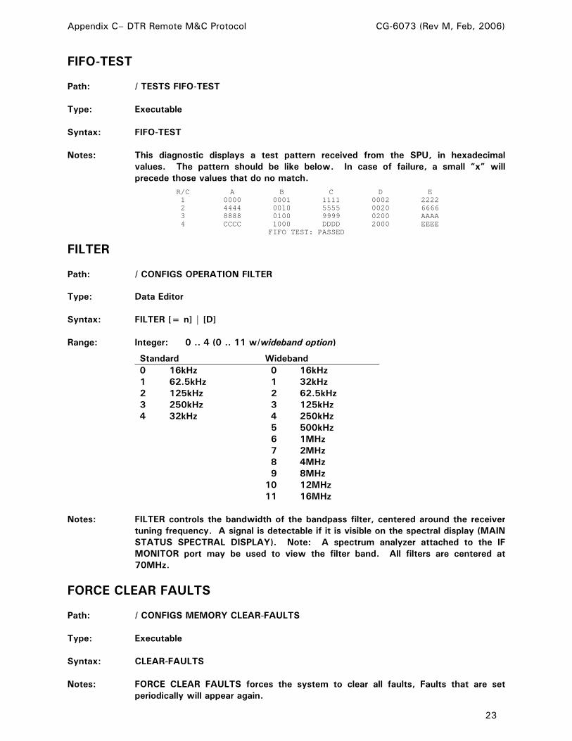
Appendix C– DTR Remote M&C Protocol CG-6073 (Rev M, Feb, 2006)
23
FIFO-TEST Path: / TESTS FIFO-TEST Type: Executable Syntax: FIFO-TEST Notes: This diagnostic displays a test pattern received from the SPU, in hexadecimal
values. The pattern should be like below. In case of failure, a small “x” will precede those values that do no match.
R/C A B C D E 1 0000 0001 1111 0002 2222 2 4444 0010 5555 0020 6666 3 8888 0100 9999 0200 AAAA 4 CCCC 1000 DDDD 2000 EEEE
FIFO TEST: PASSED
FILTER Path: / CONFIGS OPERATION FILTER Type: Data Editor Syntax: FILTER [= n] | [D] Range: Integer: 0 .. 4 (0 .. 11 w/wideband option)
Standard Wideband 0 16kHz 0 16kHz 1 62.5kHz 1 32kHz 2 125kHz 2 62.5kHz 3 250kHz 3 125kHz 4 32kHz 4 250kHz 5 500kHz 6 1MHz 7 2MHz 8 4MHz 9 8MHz 10 12MHz 11 16MHz
Notes: FILTER controls the bandwidth of the bandpass filter, centered around the receiver
tuning frequency. A signal is detectable if it is visible on the spectral display (MAIN STATUS SPECTRAL DISPLAY). Note: A spectrum analyzer attached to the IF MONITOR port may be used to view the filter band. All filters are centered at 70MHz.
FORCE CLEAR FAULTS Path: / CONFIGS MEMORY CLEAR-FAULTS Type: Executable Syntax: CLEAR-FAULTS Notes: FORCE CLEAR FAULTS forces the system to clear all faults, Faults that are set
periodically will appear again.

Appendix C– DTR Remote M&C Protocol CG-6073 (Rev M, Feb, 2006)
24
FREQ #1 IF OVERRIDE Path: / CONFIGS MEMORY CALIBRATION IF-OVERRIDE F1-OVERRIDE Type: Data Editor Syntax: F1OVERRIDE [= n] | [D] Range Integer: 0 .. 15
0 – Automatic 4 – 829.6 8 – 836.0 12 – 842.4 1 – 824.8 5 – 831.2 9 – 837.6 13 – 844.0 2 – 826.4 6 – 832.8 10 – 839.2 14 – 845.6 3 – 828.0 7 – 834.4 11 – 840.8 15 – 847.2
Notes: Allows user selection of IF1 used by the L-Band front end for the current frequency.
IF1 specifies an approximate center for the digital filter within a 25MHz analog filter centered at 836.5.
FREQ #2 IF OVERRIDE Path: / CONFIGS MEMORY CALIBRATION IF-OVERRIDE F2-OVERRIDE Type: Data Editor Syntax: F2OVERRIDE [= n] | [D] Range: Integer: 0 .. 15
0 – Automatic 4 – 829.6 8 – 836.0 12 – 842.4 1 – 824.8 5 – 831.2 9 – 837.6 13 – 844.0 2 – 826.4 6 – 832.8 10 – 839.2 14 – 845.6 3 – 828.0 7 – 834.4 11 – 840.8 15 – 847.2
Notes: Allows user selection of IF1 used by the L-Band front end for the current frequency.
IF1 specifies an approximate center for the digital filter within a 25MHz analog filter centered at 836.5.

Appendix C– DTR Remote M&C Protocol CG-6073 (Rev M, Feb, 2006)
25
FREQ #3 IF OVERRIDE Path: / CONFIGS MEMORY CALIBRATION IF-OVERRIDE F3-OVERRIDE Type: Data Editor Syntax: F3OVERRIDE [= n] | [D] Range: Integer: 0 .. 15
0 – Automatic 4 – 829.6 8 – 836.0 12 – 842.4 1 – 824.8 5 – 831.2 9 – 837.6 13 – 844.0 2 – 826.4 6 – 832.8 10 – 839.2 14 – 845.6 3 – 828.0 7 – 834.4 11 – 840.8 15 – 847.2
Notes: Allows user selection of IF1 used by the L-Band front end for the current frequency.
IF1 specifies an approximate center for the digital filter within a 25MHz analog filter centered at 836.5.
FREQ #4 IF OVERRIDE Path: / CONFIGS MEMORY CALIBRATION IF-OVERRIDE F4-OVERRIDE Type: Data Editor Syntax: F4OVERRIDE [= n] | [D] Range: Integer: 0 .. 15
0 – Automatic 4 – 829.6 8 – 836.0 12 – 842.4 1 – 824.8 5 – 831.2 9 – 837.6 13 – 844.0 2 – 826.4 6 – 832.8 10 – 839.2 14 – 845.6 3 – 828.0 7 – 834.4 11 – 840.8 15 – 847.2
Notes: Allows user selection of IF1 used by the L-Band front end for the current frequency.
IF1 specifies an approximate center for the digital filter within a 25MHz analog filter centered at 836.5.
FREQUENCY Path: / FREQUENCY Type: Data Editor Syntax: FREQUENCY [= n] | [D] Range: Real: 945.000 .. 12750.000 (v2.0.7 or later) Real: 949.000 .. 12750.000 (v2.0.4 or earlier) Notes: This is the FREQUENCY editor. The valid frequency range depends on the DTR’s
downconverter configuration.
Appendix C– DTR Remote M&C Protocol CG-6073 (Rev M, Feb, 2006)
26
HARDWARE OPTIONS (v1.19.08 or later) Path: / CONFIGS MEMORY CALIBRATION OPTIONS Type: Sub Menu Syntax: OPTIONS Notes: Contains settings for special hardware configurations. These settings are typically
made in the factory and should not be changed under normal circumstances. CHANGING THE PARAMETERS IN THIS MENU MAY DEGRADE THE PERFORMANCE OF THE DTR.
HIGH FREQ (OPTIONAL-Depending on RF Range) Path: / CONFIGS BANDS BAND-1 HIGH-FREQ Type: Data Editor Syntax: HIGH-FREQ [= n] | [D] Range: Real: 945.000 .. 13000.000 (v2.0.7 or later) Real: 949.000 .. 13000.000 (v2.0.4 or earlier) Notes: HIGH end FREQUENCY of the BDC that supports this band. Typical configurations: S-band = 2800MHz C-band = 4200MHz X-band = 7750MHz Ku-lo-band = 11700MHz Ku-hi-band = 12750MHz Ka-A = 18100, Ka-B = 19200, Ka-C = 20200, Ka-D = 21200, Ka-E = 22300
HIGH FREQ (OPTIONAL-Depending on RF Range) Path: / CONFIGS BANDS BAND-2 HIGH-FREQ Type: Data Editor Syntax: HIGH-FREQ [= n] | [D] Range: Real: 945.000 .. 13000.000 (v2.0.7 or later) Real: 949.000 .. 13000.000 (v2.0.4 or earlier) Notes: HIGH end FREQUENCY of the BDC that supports this band. Typical configurations: S-band = 2800MHz C-band = 4200MHz X-band = 7750MHz Ku-lo-band = 11700MHz Ku-hi-band = 12750MHz Ka-A = 18100, Ka-B = 19200, Ka-C = 20200, Ka-D = 21200, Ka-E = 22300

Appendix C– DTR Remote M&C Protocol CG-6073 (Rev M, Feb, 2006)
27
HIGH FREQ (OPTIONAL-Depending on RF Range) Path: / CONFIGS BANDS BAND-3 HIGH-FREQ Type: Data Editor Syntax: HIGH-FREQ [= n] | [D] Range: Real: 945.000 .. 13000.000 (v2.0.7 or later) Real: 949.000 .. 13000.000 (v2.0.4 or earlier) Notes: HIGH end FREQUENCY of the BDC that supports this band. Typical configurations: S-band = 2800MHz C-band = 4200MHz X-band = 7750MHz Ku-lo-band = 11700MHz Ku-hi-band = 12750MHz Ka-A = 18100, Ka-B = 19200, Ka-C = 20200, Ka-D = 21200, Ka-E = 22300
HIGH FREQ (OPTIONAL-Depending on RF Range) Path: / CONFIGS BANDS BAND-4 HIGH-FREQ Type: Data Editor Syntax: HIGH-FREQ [= n] | [D] Range: Real: 945.000 .. 13000.000 (v2.0.7 or later) Real: 949.000 .. 13000.000 (v2.0.4 or earlier) Notes: HIGH end FREQUENCY of the BDC that supports this band. Typical configurations: S-band = 2800MHz C-band = 4200MHz X-band = 7750MHz Ku-lo-band = 11700MHz Ku-hi-band = 12750MHz Ka-A = 18100, Ka-B = 19200, Ka-C = 20200, Ka-D = 21200, Ka-E = 22300
HIGH TEMP LIMIT (v1.16.51 or later) Path: / CONFIGS UI-OPTIONS TEMP-LIMIT Type: Data Editor Syntax: TEMP-LIMIT [= n] Range: 0 .. 140 Notes: This value, in degrees Fahrenheit, is used to trigger the TEMPERATURE ALARM
fault. The default value is 120 degrees F.

Appendix C– DTR Remote M&C Protocol CG-6073 (Rev M, Feb, 2006)
28
INPUT ATTEN (v1.19.15 or later) Path: / INPUT-ATTEN Type: Data Editor Syntax: INPUT-ATTEN [= n] | [D] Range: Integer: 0 .. 15
0 – 0 dB 2 – 4 dB 4 – 8 dB 6 – 12 dB 8 – 16 dB 10 – 20 dB 12 – 24 dB 14 – 28 dB 1 – 2 dB 3 – 6 dB 5 – 10 dB 7 – 14 dB 9 – 18 dB 11 – 22 dB 13 – 26 dB 15 – 30 dB Notes: INPUT ATTEN controls the attenuator in the RF front-end. The specified attenuation
is applied inside the RF front-end, after the first amplifier but before the first stage mixer.
Also see: CONFIGS, RECEIVER OPERATION, ANALOG OUTPUTS, ATTENUATION.
INTERFACE OPTIONS Path: / CONFIGS UI-OPTIONS Type: Sub-Menu Syntax: UI-OPTIONS Notes: Allows control of options related to the DTR user interface.
I/O STATUS Path: / STATUS I/O-STATUS Type: Executable Syntax: I/O-STATUS Notes: Displays current I/O status info obtained from the I/O card. The I/O STATUS M&C
request returns the same information as the front panel I/O STATUS screen. Below is an example from a terminal program. The content (especially for the internal configuration values) and format is subject to change without notice:
>I/O-STATUS INTF #1 IN= ~~ OUT= 00 INTF #2 IN= FF OUT= 00 BDC POWER IN= 2(3) BDC SELECTED=D(3) FAULTS=C ok BDC POWER OUT=59(3) BDC SELECT=2(3) SPDTX4 SW IN=FF(----) SPDTX4 SW OUT=AA (Hi22) PLL VOLTAGES (VOLTS): PLL1=11.30 PLL2=1.70 TEMPERATURES (DEG F): LBFE=76.4 SPU=91.5 >
IS LBAND? (v1.16.51 through v1.19.06) Notes: This parameter became LBAND-DEFAULTS in v1.19.07.

Appendix C– DTR Remote M&C Protocol CG-6073 (Rev M, Feb, 2006)
29
LBAND-DEFAULTS (v1.19.07 or later) Path: / CONFIGS BANDS BAND-1 LBAND-DEFAULTS Type: Executable Syntax: LBAND-DEFAULTS Notes: Sets BAND-1 parameters to L-Band defaults. From v1.16.51 to v1.19.06, this
parameter was called IS-LBAND?.
LCD DISPLAY Path: / CONFIGS TESTS LCD-TEST Type: Data Editor Syntax: LCD-TEST Notes: LCD DISPLAY tests every pixel of the LCD by drawing lines in two alternating
patterns. The first pattern displays automatically; the second pattern will display after a key-press. Press any key to exit test.
LCD CONTRAST Path: / CONFIGS UI-OPTIONS CONTRAST Type: Data Editor Syntax: CONTRAST [= n] Range: Real: 0 .. 30 Notes: Use LCD Contrast to adjust the contrast of the LCD display. Choose a value
between 0 (for least contrast) and 30 (for maximum contrast). Six is default value.
LEDS TEST Path: / CONFIGS TESTS LEDS-TEST Type: Executable Syntax: LEDS-TEST Notes: LEDS TEST blinks the top three status LED's four times. The Power LED does not
blink.

Appendix C– DTR Remote M&C Protocol CG-6073 (Rev M, Feb, 2006)
30
LOW FREQ (OPTIONAL-Depending on RF Range) Path: / CONFIGS BANDS BAND-1 LOW-FREQ Type: Data Editor Syntax: LOW-FREQ [= n] | [D] Range: Real: 945.000 .. 13000.000 (v2.0.7 or later) Real: 949.000 .. 13000.000 (v2.0.4 or earlier) Notes: LOW end FREQUENCY of the BDC that supports this band. Typical configurations: S-band = 2000MHz C-band = 3400MHz X-band = 7250MHz Ku-lo-band = 10700MHz Ku-hi-band = 11700MHz Ka-A = 17000, Ka-B = 18100, Ka-C = 19200, Ka-D = 20200, Ka-E = 21200
LOW FREQ (OPTIONAL-Depending on RF Range) Path: / CONFIGS BANDS BAND-2 LOW-FREQ Type: Data Editor Syntax: LOW-FREQ [= n] | [D] Range: Real: 945.000 .. 13000.000 (v2.0.7 or later) Real: 949.000 .. 13000.000 (v2.0.4 or earlier) Notes: LOW end FREQUENCY of the BDC that supports this band. Typical configurations: S-band = 2000MHz C-band = 3400MHz X-band = 7250MHz Ku-lo-band = 10700MHz Ku-hi-band = 11700MHz Ka-A = 17000, Ka-B = 18100, Ka-C = 19200, Ka-D = 20200, Ka-E = 21200
LOW FREQ (OPTIONAL-Depending on RF Range) Path: / CONFIGS BANDS BAND-3 LOW-FREQ Type: Data Editor Syntax: LOW-FREQ [= n] | [D] Range: Real: 945.000 .. 13000.000 (v2.0.7 or later) Real: 949.000 .. 13000.000 (v2.0.4 or earlier) Notes: LOW end FREQUENCY of the BDC that supports this band. Typical configurations: S-band = 2000MHz C-band = 3400MHz X-band = 7250MHz Ku-lo-band = 10700MHz Ku-hi-band = 11700MHz Ka-A = 17000, Ka-B = 18100, Ka-C = 19200, Ka-D = 20200, Ka-E = 21200

Appendix C– DTR Remote M&C Protocol CG-6073 (Rev M, Feb, 2006)
31
LOW FREQ (OPTIONAL-Depending on RF Range) Path: / CONFIGS BANDS BAND-4 LOW-FREQ Type: Data Editor Syntax: LOW-FREQ [= n] | [D] Range: Real: 945.000 .. 13000.000 (v2.0.7 or later) Real: 949.000 .. 13000.000 (v2.0.4 or earlier) Notes: LOW end FREQUENCY of the BDC that supports this band. Typical configurations: S-band = 2000MHz C-band = 3400MHz X-band = 7250MHz Ku-lo-band = 10700MHz Ku-hi-band = 11700MHz Ka-A = 17000, Ka-B = 18100, Ka-C = 19200, Ka-D = 20200, Ka-E = 21200
LOW SIGNAL LEVEL Path: / CONFIGS UI-OPTIONS LOW-SIGNAL-LEVEL Type: Data Editor Syntax: LOW-SIGNAL-LEVEL [= n] | [D] Range: Real: -199.00 .. -1.00 Notes: This value, in dB, is used to trigger the low input signal fault.
LOW SIGNAL ALARM Path: / CONFIGS UI-OPTIONS LOW-SIGNAL-ALARM Type: Data Editor Syntax: LOW-SIGNAL-ALARM [= n] Range: 0 (“disabled”)…1 (“enabled”) Notes: Enables the Low Input Signal alarm, allowing the fault to be reported. This is not
useful for most applications and is disabled by default.

Appendix C– DTR Remote M&C Protocol CG-6073 (Rev M, Feb, 2006)
32
MANUAL IF OVERRIDE Path: / CONFIGS MEMORY CALIBRATION IF-OVERRIDE Type: Sub Menu Syntax: IF-OVERRIDE Notes: The IF OVERRIDE menu allows the user to manually select the IF used by the L-
Band front end. The DTR normally selects the optimal IF; this menu provides flexibility for special cases.
MASTER ADDRESS (v 1.19.06 or later) Path: / CONFIGS COMM-PARAM PORT-3 MASTER-ADDRESS Type: Data Editor Syntax: MASTER-ADDRESS [= n] | [D] Range: Integer: 0 .. 31 Notes: MASTER-ADDRESS is the address of the master (controlling) device on the multi-
drop RS-485 bus. There are a maximum on 32 addresses, ranging from 0 to 31. On the bus, the actual ASCII value used for addressing is the address assigned here plus the value of the parameter ADDRESS OFFSET.
MESSAGE LOG Path: / STATUS LOG Type: Executable Syntax: LOG Notes: The MESSAGE LOG displays the most recent events recorded in system’s message
log. The latest message is at bottom of the screen and pressing SHIFT-PAGE scrolls the list to display previous messages.
MINIMUM REF LVL Path: / CONFIGS OPERATION ANALOG-OUTPUTS DAC1 DAC1-REF Type: Data Editor Syntax: REFERENCE [= n] | [D] Range: Real: -150.0 .. 20.0 Notes: The MINIMUM REF POWER LVL is the minimum input power level reference which
corresponds to minimum DAC voltage output.

Appendix C– DTR Remote M&C Protocol CG-6073 (Rev M, Feb, 2006)
33
MINIMUM REF LVL Path: / CONFIGS OPERATION ANALOG-OUTPUTS DAC2 DAC2-REF Type: Data Editor Syntax: REFERENCE [= n] | [D] Range: Real: -150.0 .. 20.0 Notes: The MINIMUM REF POWER LVL is the minimum input power level reference which
corresponds to minimum DAC voltage output.
MUTE Path: / CONFIGS MONOPULSE Type: Data Editor Syntax: MUTE [= n] | [D] Range: Integer: 0 .. 1 0 Disabled 1 Enabled Notes: MUTE controls the combination of signal and error channels in the monopulse
hardware. Disable to include the error channel for monopulse operation. Enable to exclude the error channel for normal operation. NOTE: This can also be set by M&C commands in TRL-Emulation.
MUTE FAULT Path: / CONFIGS MONOPULSE Type: Data Editor Syntax: MUTE-FAULT [= n] | [D] Range: Integer: 0 .. 1 0 Disabled 1 Enabled Notes: MUTE-FAULT enables or disables the mute switch fault. This feature should be
disabled for monopulse plates which do not support mute switch feedback. Disabling the fault on systems that support mute switch failure detection is not recommended for normal operation. Feedback is provided via mute status lines on I/O interface 2.

Appendix C– DTR Remote M&C Protocol CG-6073 (Rev M, Feb, 2006)
34
MODE Path: / CONFIGS MONOPULSE Type: Data Editor Syntax: MODE [= n] | [D] Range: Integer: 0 .. 1 0 Vectors 1 Levels Notes: MODE sets the type of monopulse output of START, either two error vectors with
sum for normal operation or four phase levels for diagnostics. All output is in hexadecimal:
0:VECTORS reply: "[+|-]ddddd [+|-]eeeee -fffff" where d and e units are |dBm/10000| and f units are |dBm/1000| (range 0 to -262.143 dBm) 1:LEVELS reply: "+dddddd +eeeeee +ffffff +gggggg" where units are |dBm/1000| NOTE: Also set by M&C in TRL-Emulation
NCO OFFSET Path: / CONFIGS MEMORY CALIBRATION NCO Type: Data Editor Syntax: NCO [= n] | [D] Range: Real: -6000.000 .. 99999.999 Notes: Adjusts the frequency of the Numerically Controlled Oscillator (NCO) on the SPU.
NEWLINE Path: / CONFIGS COMM-PARAM PORT-1 NEWLINE Type: Data Editor Syntax: NEWLINE [= n] | [D] Range: Integer: 0 .. 1 0 Disabled 1 Enabled Notes: NEWLINE, when enabled, sends a carriage-return line-feed at the end of the
command line. When disabled, only carriage return is sent.

Appendix C– DTR Remote M&C Protocol CG-6073 (Rev M, Feb, 2006)
35
NEWLINE Path: / CONFIGS COMM-PARAM PORT-2 NEWLINE Type: Data Editor Syntax: NEWLINE [= n] | [D] Range: Integer: 0 .. 1 0 Disabled 1 Enabled Notes: NEWLINE, when enabled, sends a carriage-return line-feed at the end of the
command line. When disabled, only carriage-return is sent.
OSC FREQ (OPTIONAL-Depending on RF Range) Path: / CONFIGS BANDS BAND-1 OSC-FREQ Type: Data Editor Syntax: OSC-FREQ [= n] | [D] Range: Real: 100.000 .. 15000.000 Notes: LOCAL OSCILLATOR of the BDC that supports this band. Typical configurations: S-band = 3750MHz C-band = 5150MHz X-band = 6300MHz Ku-lo-band = 9750MHz Ku-hi-band = 10750MHz Ka-A = 16500, Ka-B = 17150, Ka-C = 18250, Ka-D = 19250, Ka-E = 20250
OSC FREQ (OPTIONAL-Depending on RF Range) Path: / CONFIGS BANDS BAND-2 OSC-FREQ Type: Data Editor Syntax: OSC-FREQ [= n] | [D] Range: Real: 100.000 .. 15000.000 Notes: LOCAL OSCILLATOR of the BDC that supports this band. Typical configurations: S-band = 3750MHz C-band = 5150MHz X-band = 6300MHz Ku-lo-band = 9750MHz Ku-hi-band = 10750MHz Ka-A = 16500, Ka-B = 17150, Ka-C = 18250, Ka-D = 19250, Ka-E = 20250

Appendix C– DTR Remote M&C Protocol CG-6073 (Rev M, Feb, 2006)
36
OSC FREQ (OPTIONAL-Depending on RF Range) Path: / CONFIGS BANDS BAND-3 OSC-FREQ Type: Data Editor Syntax: OSC-FREQ [= n] | [D] Range: Real: 100.000 .. 15000.000 Notes: LOCAL OSCILLATOR of the BDC that supports this band. Typical configurations: S-band = 3750MHz C-band = 5150MHz X-band = 6300MHz Ku-lo-band = 9750MHz Ku-hi-band = 10750MHz Ka-A = 16500, Ka-B = 17150, Ka-C = 18250, Ka-D = 19250, Ka-E = 20250
OSC FREQ (OPTIONAL-Depending on RF Range) Path: / CONFIGS BANDS BAND-4 OSC-FREQ Type: Data Editor Syntax: OSC-FREQ [= n] | [D] Range: Real: 100.000 .. 15000.000 Notes: LOCAL OSCILLATOR of the BDC that supports this band. Typical configurations: S-band = 3750MHz C-band = 5150MHz X-band = 6300MHz Ku-lo-band = 9750MHz Ku-hi-band = 10750MHz Ka-A = 16500, Ka-B = 17150, Ka-C = 18250, Ka-D = 19250, Ka-E = 20250
POL INPUTS (v1.19.08 or later) Path: /CONFIGS MEMORY CALIBRATION OPTIONS POL-INPUTS Type: Data Editor Syntax: POL-INPUTS [= n] | [D] Range: Integer: 0 .. 1 0 Standard 1 4 Ports Notes: 4 Ports is an optional hardware configuration that provides four discreet inputs for a
single band. Selecting the 4 inputs option will provide for POL inputs 1..4 in the POL SELECT menu. Default is STANDARD. Select 4 Ports ONLY if the correct hardware is installed.

Appendix C– DTR Remote M&C Protocol CG-6073 (Rev M, Feb, 2006)
37
POL SELECT Path: / POL SELECT Type: Data Editor Syntax: POL-SELECT [= n] | [D] Range: Integer: 1 .. 2 1 Pol 1 2 Pol 2 Notes: POL SELECT selects which POL input will be used for tracking. This setting is used
to control an RF switch internal to the DTR, and may also be used to control an external switch using I/O Interface #1 on the back panel. GPIO 6 and 7 become active based on the POL SELECT setting. Pins 11,24 represent the POL1 state and pins 11,25 represent the POL2 state. These pin groups are connected to dry relay contacts (1Amp max current).
POL SELECT (FOUR PORTS OPTION ONLY) (v1.19.08 or later) Path: / POL-SELECT Type: Data Editor Syntax: POL-SELECT [= n] | [D] Range: Integer: 1 .. 4 1 Pol 1
2 Pol 2 3 Pol 3 4 Pol 4
Notes: POL-SELECT selects which POL input will be used for tracking. This setting is used
to control an RF switch internal to the DTR, and may also be used to control an external switch using I/O Interface #1 on the back panel. GPIO 4, 5, 6 and 7 become active based on the POL SELECT setting. Pins 11,24 represent the POL1 state , pins 12,25 represent the POL2 state, pins 9,22 represent the POL3 state, and pins 10,12 represent the POL4 state. These pin groups are connected to dry relay contacts (1Amp max current).
PORT 1 Path: / CONFIGS COMM-PARAM PORT-1 Type: Sub Menu Syntax: PORT-1 Notes: PORT 1 is an RS-232 (only) port used for remote M&C communications. The data
parameters are set in factory to: 8 data bits, 1 stop bit, no parity. Port 1 is available on the back panel as a 9-pin D subminiature socket connector with the following electrical pinout: pin 2=RX (from DCE); pin 3=TX (from DTE); pin 5=Signal Ground. The other pins are not connected.
Appendix C– DTR Remote M&C Protocol CG-6073 (Rev M, Feb, 2006)
38
PORT 2 Path: / CONFIGS COMM-PARAM PORT-2 Type: Sub Menu Syntax: PORT-2 Notes: PORT 2 is used for M&C operation and allows RS-232 and RS-422 connections. .
The data parameters are set in factory to: 8 Data bits, 1 Stop bit, No Parity. PORT 2 is available on the back panel as a 9 pin D subminiature socket connector. The RS-232 electrical pinout is: pin 2=RX (from DCE); pin 3=TX (from DTE); pin 5=Signal Ground; pin 7=RTS (from DTE); pin 8=CTS (from DCE); The RS-422 electrical pinout is: pin 1=TX+; pin 4=RX+; pin 6=TX-; pin 9=RX-. Notice that these two pinouts coexist on the same 9 pin connector without conflict.
PORT 3 (v 1.19.06 or later) Path: / CONFIGS COMM-PARAM PORT-3 Type: Sub Menu Syntax: PORT-3 Notes: PORT 3 is used for M&C communications on a multi-drop half-duplex 485 bus. This
menu controls the BPS, SHELL, and bus addressing parameters of this PORT. Notice that the data parameters are set in factory to: 8 Data bits, 1 Stop bit, No Parity. PORT 3 is available on the back panel as a 9 pin D subminiature socket connector.
The RS-485 electrical pinout is: Pin 7 = Cable Shield Pin 1 = Data+(RxD/TxD +) Pin 6 = Data- (RxD/TxD -)
POWER LEVEL CALIBRATION Path: / CONFIGS MEMORY CALIBRATION CALIBRATION Type: Data Editor Syntax: CALIBRATION [= n] | [D] Range: Real: -99.99 .. 99.99 Notes: POWER LEVEL CALIBRATION adjusts the calibration value used to calculate the
signal power measurement reported by the DTR (shown on the front display in dBm). This parameter should NOT be modified under normal cirumstances.

Appendix C– DTR Remote M&C Protocol CG-6073 (Rev M, Feb, 2006)
39
RATE Path: / CONFIGS MONOPULSE Type: Data Editor Syntax: RATE [= n] | [D] Range: Integer: -1 .. 10000 Notes: RATE is the minimum number of milliseconds between the monopulse data
transmissions of START. If the value is -1, new data is sent only after receiving a carriage return. NOTE: Also used by M&C in TRL-Emulation
RECEIVER OPERATION Path: / CONFIGS OPERATION Type: Sub Menu Syntax: OPERATION Notes: RECEIVER OPERATION configures how the Signal Processing Unit (SPU) will
process the signal.
REMOTE CONTROL Path: / CONFIGS COM-PARAM REM-CONTROL Type: Data Editor Syntax: REM-CONTROL [= n] | [D] Range: Integer: 0 .. 3 0 I/O INTF #1 1 PORT 1
2 PORT 2 3 PORT 3
Notes: REMOTE CONTROL selects which port on back panel is in control when the DTR is
in REMOTE mode. For remote M&C communications select PORT 1, 2, or 3 which support serial protocols. To control the DTR via discrete digital I/O select I/O INTF #1, which will allow a remote device (such as 7134ACU) to select a BEACON using a cable connected to I/O INTERFACE #1 on the back panel and the STORE/RESTORE BEACONS menus. The pinout of I/O INTERFACE # 1 includes: Pins 5,18, GPIO 0, = Beacon 1 Input; Pins 6,19, GPIO 1, = Beacon 2 Input; Pins 7,20, GPIO 2, = Beacon 3 Input; Pins 8,21, GPIO 3, = Beacon 4 Input.

Appendix C– DTR Remote M&C Protocol CG-6073 (Rev M, Feb, 2006)
40
RESET PORT Path: / CONFIGS COMM-PARAM PORT-1 RESET-PORT Type: Executable Syntax: RESET-PORT Notes: RESET-PORT resets the given port. The electrical interface is initialized and the
shell (if any) that was running on it is restarted.
RESET PORT Path: / CONFIGS COMM-PARAM PORT-2 RESET-PORT Type: Executable Syntax: RESET-PORT Notes: RESET-PORT resets the given port. The electrical interface is initialized and the
shell (if any) that was running on it is restarted.
RESET PORT Path: / CONFIGS COMM-PARAM PORT-3 RESET-PORT Type: Executable Syntax: RESET-PORT Notes: RESET-PORT resets the given port. The electrical interface is initialized and the
shell (if any) that was running on it is restarted.
RESTORE BEACONS Path: / CONFIGS BEACONS RESTORE-BEACONS Type: Sub Menu Syntax: RESTORE-BEACONS Notes: Executing each item in this menu will RESTORE values previously stored as a
BEACON state: FREQUENCY, INPUT ATTEN, POL SELECT, FILTER, SLOPE, VOLT RANGE, MIN REF LVL, and ATTENUATION.

Appendix C– DTR Remote M&C Protocol CG-6073 (Rev M, Feb, 2006)
41
RESTORE BEACON1 Path: / CONFIGS BEACONS RESTORE-BEACONS RESTORE-BEACON1 Type: Executable Syntax: RESTORE-BEACON1 Notes: Executing each item in this menu will RESTORE values previously stored as a
BEACON state: FREQUENCY, INPUT ATTEN, POL SELECT, FILTER, SLOPE, VOLT RANGE, MIN REF LVL, and ATTENUATION.
RESTORE BEACON2 Path: / CONFIGS BEACONS RESTORE-BEACONS RESTORE-BEACON2 Type: Executable Syntax: RESTORE-BEACON2 Notes: Executing each item in this menu will RESTORE values previously stored as a
BEACON state: FREQUENCY, INPUT ATTEN, POL SELECT, FILTER, SLOPE, VOLT RANGE, MIN REF LVL, and ATTENUATION.
RESTORE BEACON3 Path: / CONFIGS BEACONS RESTORE-BEACONS RESTORE-BEACON3 Type: Executable Syntax: RESTORE-BEACON3 Notes: Executing each item in this menu will RESTORE values previously stored as a
BEACON state: FREQUENCY, INPUT ATTEN, POL SELECT, FILTER, SLOPE, VOLT RANGE, MIN REF LVL, and ATTENUATION.
RESTORE BEACON4 Path: / CONFIGS BEACONS RESTORE-BEACONS RESTORE-BEACON4 Type: Executable Syntax: RESTORE-BEACON4 Notes: Executing each item in this menu will RESTORE values previously stored as a
BEACON state: FREQUENCY, INPUT ATTEN, POL SELECT, FILTER, SLOPE, VOLT RANGE, MIN REF LVL, and ATTENUATION.
Appendix C– DTR Remote M&C Protocol CG-6073 (Rev M, Feb, 2006)
42
RESTORE ROM DEFAULTS Path: / CONFIGS MEMORY RESTORE-TO-ROM-DEFAULTS Type: Data Editor Syntax: RESTORE-TO-ROM-DEFAULTS [= n] | [D] Range: Integer: 0 .. 1 0 No 1 Yes Notes: Selecting YES and pressing ENTER restores all DTR parameters to factory ROM
defaults. If this is done, the front panel (not the whole DTR) will reset.
SAMPLING FREQUENCY Path: / CONFIGS MEMORY CALIBRATION SAMPLING Type: Data Editor Syntax: SAMPLING [= n] | [D] Range: Real: 63990.000 .. 64010.000 Notes: SAMPLING FREQUENCY compensates for the oscillator’s slight deviation from
64MHz. Entering the actual oscillator frequency to within 1Hz maximizes the receiver’s performance.
SET DATE AND TIME Path: / CONFIGS MEMORY DATE&TIME Type: Sub Menu Syntax: DATE&TIME Notes: The SET DATE and TIME menu contains editors for setting the date and time. The
port used to set the date or time with (local or remote) must be the one in control.
SET DATE Path: / CONFIGS MEMORY DATE&TIME SET-DATE Type: Data Editor Syntax: SET-DATE [= n] | [D] Range: Integer: 1011980 .. 12312079 (Must be a valid date) Notes: Changing this changes the current date. Under the menu tree shell the format is
MMDDYYYY and all fields must be set.

Appendix C– DTR Remote M&C Protocol CG-6073 (Rev M, Feb, 2006)
43
SET TIME Path: / CONFIGS MEMORY DATE&TIME SET-TIME Type: Data Editor Syntax: SET-TIME [= n] | [D] Range: Integer: 000000 to 235959 (Must be a valid time) Notes: Changing this changes the current time ( in 24 hour format). Under the menu tree
shell the format is HHMMSS and all fields must be set.
SHELL Path: / CONFIGS COMM-PARAM PORT-1 SHELL or / CONFIGS COMM-PARAM PORT-2 SHELL Type: Data Editor Syntax: SHELL [= n] | [D] Range: Integer: 0 .. 4 0 Disabled 1 M&C Shell
2 Message Printer 3 Data Reader 4 72xx M&C Shell
Notes: SHELL determines the communications protocol used on this serial port. M&C Shell
provides monitor and control protocol support including status polling and system configuration capability. 72xx M&C Shell provides TRL Monitor and Control protocol support for status polling and system configuration by a 72xx ACU with version 2 firmware. An ACU remote port set to DTR and a DTR set to 72xx M&C SHELL will NOT communicate. Message Printer is a diagnostic tool which may be used to record system events, when connected to a terminal program or a serial printer.
SHELL (v 1.19.06 or later) Path: / CONFIGS COMM-PARAM PORT-3 SHELL Type: Data Editor Syntax: SHELL [= n] | [D] Range: Integer: 0 .. 1 0 Disabled 1 M&C Shell Notes: SHELL determines the communications protocol used on this serial port. M&C Shell
provides monitor and control protocol support including status polling and system configuration capability. The PORT-3 shell was added in v1.19.06.

Appendix C– DTR Remote M&C Protocol CG-6073 (Rev M, Feb, 2006)
44
SLAVE ADDRESS (v 1.19.06 or later) Path: / CONFIGS COMM-PARAM PORT-3 SLAVE-ADDRESS Type: Data Editor Syntax: SLAVE-ADDRESS [= n] | [D] Range: Integer: 0 .. 31 Notes: SLAVE-ADDRESS is the address of this unit (a slave, controlled) on the multi-drop
RS-485 bus. There are a maximum on 32 addresses, ranging from 0 to 31. On the bus, the actual ASCII value used for addressing is the address assigned here plus the value of the parameter ADDRESS OFFSET.
SLOPE Path: / CONFIGS OPERATION ANALOG-OUTPUTS DAC1 DAC1-SLOPE Type: Data Editor Syntax: DAC1-SLOPE [= n] | [D] Range: Real: -1.000 .. 1.000 (volts/dB) Notes: SLOPE controls the rate of change of the DC output voltage with respect to a 1 dB
change in signal power level.
SLOPE Path: / CONFIGS OPERATION ANALOG-OUTPUTS DAC2 DAC2-SLOPE Type: Data Editor Syntax: DAC2-SLOPE [= n] | [D] Range: Real: -1.000 .. 1.000 (volts/dB) Notes: SLOPE controls the rate of change of the DC output voltage with respect to a 1 dB
change in signal power level.

Appendix C– DTR Remote M&C Protocol CG-6073 (Rev M, Feb, 2006)
45
SPECTRAL DISPLAY (v2.0.7 or later) Path: / STATUS SPECTRAL-DISPLAY Type: Executable Syntax: SPECTRAL-DISPLAY Notes: SPECTRAL DISPLAY plots the signal's frequency components in a graphical manner
similar to a spectrum analyzer. Use the Spin Knob to adjust frequency. Soft keys A/B change step size. Soft keys C/D change vertical scale. Press PREV to exit. The M&C command outputs spectral data using the following format:
HEADER: freq, Sig, C/No, BW, Scale(CR) BODY: 256 encoded data points(CR) FOOTER: Elapsed Time in ms.(CR) Each data point is 1 to 64, encoded as a single character (ascii 49 to 112) Reference:
Dec Chr Data Dec Chr Data Dec Chr Data Dec Chr Data
49 1 1 65 A 17 81 Q 33 97 a 49 50 2 2 66 B 18 82 R 34 98 b 50 51 3 3 67 C 19 83 S 35 99 c 51 52 4 4 68 D 20 84 T 36 100 d 52 53 5 5 69 E 21 85 U 37 101 e 53 54 6 6 70 F 22 86 V 38 102 f 54 55 7 7 71 G 23 87 W 39 103 g 55 56 8 8 72 H 24 88 X 40 104 h 56 57 9 9 73 I 25 89 Y 41 105 i 57 58 : 10 74 J 26 90 Z 42 106 j 58 59 ; 11 75 K 27 91 [ 43 107 k 59 60 < 12 76 L 28 92 \ 44 108 l 60 61 = 13 77 M 29 93 ] 45 109 m 61 62 > 14 78 N 30 94 ^ 46 110 n 62 63 ? 15 79 O 31 95 _ 47 111 o 63 64 @ 16 80 P 32 96 ` 48 112 p 64
Sample Output: 1014000,3631,4527,125,17
>7?D@<<:;;:48A===?A???DIGFILJJHIEHDCJI@DBCFEC;>CA:<8:>>539;9>?;515:=:;?:=866>837857;<728;<468889:=6;=?8931698=A@A=;;=A@<ACEZekgYOL=CFCBBBNQUKJ>9@<B>9;<A@9;<;==?@A:;=@;:>56<9367897?;9?:312:849;=935;:<9:999??85>;16=?=;=<;<:79B@:?:468:<D<7989:886;@;9:@=9<>><C 38
Frame Rate: @ 19,200 -> 6 fps
@ 57,600 -> 15 fps @ 119,200 -> 30 fps

Appendix C– DTR Remote M&C Protocol CG-6073 (Rev M, Feb, 2006)
46
SPU SERIAL LINK STATS Path: / STATUS SPU-DIAG Type: Executable Syntax: SPU-DIAG Notes: Displays the SPU RS422 serial link statistics separated by destination (MCU and
DSP): Timeouts – the CPU did not get a response within 100mSec. Errors – unexpected responses that do not match the internal protocol. % of Total – indicates the percentage of errors plus timeouts versus the total number of commands. Linklosses – counts the number of failures to establish communication with the MCU or DSP processors. Total – sum total of commands sent.
START Path: / CONFIGS MONOPULSE Type: Executable Syntax: START Notes: START monopulse operation; to stop, use EXIT followed by a carriage return. It
stops automatically if and when a fault is set. After stopping, in either case, the mute switch is enabled. NOTE: Only usable via the M&C
STATUS (v1.16.51 or later) Path: / STATUS Type: Sub Menu Syntax: STATUS Notes: The STATUS menu contains useful diagnostic tools. The SPECTRAL DISPLAY
option is accessed from this menu, as are other tools, such as a I/O status and the message log. This parameter was called DIAGS prior to v1.16.51.
STORE BEACONS Path: / CONFIGS BEACONS STORE-BEACONS Type: Sub Menu Syntax: STORE-BEACONS Notes: Executing each item in this menu will STORE CURRENT values of the following
parameters as a BEACON state: FREQUENCY, INPUT ATTEN, POL SELECT, FILTER, SLOPE, VOLT RANGE, MIN REF LVL, and ATTENUATION.

Appendix C– DTR Remote M&C Protocol CG-6073 (Rev M, Feb, 2006)
47
STORE BEACON1 Path: / CONFIGS BEACONS STORE-BEACONS STORE-BEACON1 Type: Executable Syntax: STORE-BEACON1 Notes: Executing each item in this menu will STORE CURRENT values of the following
parameters as a BEACON state: FREQUENCY, INPUT ATTEN, POL SELECT, FILTER, SLOPE, VOLT RANGE, MIN REF LVL, and ATTENUATION.
STORE BEACON2 Path: / CONFIGS BEACONS STORE-BEACONS STORE-BEACON2 Type: Executable Syntax: STORE-BEACON2 Notes: Executing each item in this menu will STORE CURRENT values of the following
parameters as a BEACON state: FREQUENCY, INPUT ATTEN, POL SELECT, FILTER, SLOPE, VOLT RANGE, MIN REF LVL, and ATTENUATION.
STORE BEACON3 Path: / CONFIGS BEACONS STORE-BEACONS STORE-BEACON3 Type: Executable Syntax: STORE-BEACON3 Notes: Executing each item in this menu will STORE CURRENT values of the following
parameters as a BEACON state: FREQUENCY, INPUT ATTEN, POL SELECT, FILTER, SLOPE, VOLT RANGE, MIN REF LVL, and ATTENUATION.
STORE BEACON4 Path: / CONFIGS BEACONS STORE-BEACONS STORE-BEACON4 Type: Executable Syntax: STORE-BEACON4 Notes: Executing each item in this menu will STORE CURRENT values of the following
parameters as a BEACON state: FREQUENCY, INPUT ATTEN, POL SELECT, FILTER, SLOPE, VOLT RANGE, MIN REF LVL, and ATTENUATION.

Appendix C– DTR Remote M&C Protocol CG-6073 (Rev M, Feb, 2006)
48
SYSTEM MEMORY Path: / CONFIGS MEMORY Type: Sub Menu Syntax: MEMORY Notes: The MEMORY menu contains commands relating to the storage of system
parameters that are stored in nonvolatile RAM (NVRAM).
TESTS Path: / TESTS Type: Sub Menu Syntax: TESTS Notes: The TESTS menu provides system integrity tests. These tests are primarily
intended for VertexRSI factory testing. USE OF SOME TESTS MAY OBSCURE REAL TIME DATE, AND OTHERS MAY TEMPORARILY AFFECT THE PERFORMANCE OF THIS RECEIVER.
TROUBLESHOOT Path: / STATUS TROUBLESHOOT Type: Executable Syntax: TROUBLESHOOT Notes: This is a diagnostic tool to provide online help information on the current faults.
VOLTAGE RANGE Path: / CONFIGS OPERATION ANALOG-OUTPUTS DAC1 DAC1-RANGE Type: Data Editor Syntax: DAC1-RANGE [= n] | [D] Range: Integer: 0 .. 2 0 0 to +10 1 -10 to +10 2 -5 to +5 Notes: The DC VOLTAGE RANGE of the Digital to Analog Converter. Used to represent the
signal level as a tracking voltage.

Appendix C– DTR Remote M&C Protocol CG-6073 (Rev M, Feb, 2006)
49
VOLTAGE RANGE Path: / CONFIGS OPERATION ANALOG-OUTPUTS DAC2 DAC2-RANGE Type: Data Editor Syntax: DAC2-RANGE [= n] | [D] Range: Integer: 0 .. 2 0 0 to +10 1 -10 to +10 2 -5 to +5 Notes: The DC VOLTAGE RANGE of the Digital to Analog Converter. Used to represent the
signal level as a tracking voltage.

Appendix C– DTR Remote M&C Protocol CG-6073 (Rev M, Feb, 2006)
50
5.1 Keyword Commands A keyword is a command that is always accessible on the command line, regardless of the current menu or system configuration. Unlike generic menu items, which are subject to change with firmware revisions, the keywords form the basis of the command-line interface, and thus will remain available for future revisions. Keywords, like all other items entered on the command line, must be separated from other fields with at least one space. Most keywords do not accept arguments.
/ Path: Keyword Type: Executable Syntax: / Notes: This keyword returns to the top of the menu tree.
\ Path: Keyword Type: Executable Syntax: \ Notes: This keyword is a comment character. Rest of line is ignored.
.. Path: Keyword Type: Executable Syntax: .. Notes: This keyword moves up to the parent menu of the current menu in the menu tree.

Appendix C– DTR Remote M&C Protocol CG-6073 (Rev M, Feb, 2006)
51
? Path: Keyword Type: Executable Syntax: ? Notes: Aliases: "HELP", "help", and "?". The command interpreter is case sensitive. Most
items are in caps. If a keyword or item number follows, then its help is displayed. Type KEYS in followed by carriage-return for a list of keywords. LS lists non-keyword menu items.
C# Path: Keyword Type: Executable Syntax: C# Notes: Native and TRL EMULATION MODE keyword. This keyword requests receiver port
in use; response is port #.
DATE Path: Keyword Type: Executable Syntax: DATE Notes: This keyword displays the current date.
DOWNLOAD-PARAMS Path: Keyword Type: Executable Syntax: DOWNLOAD-PARAMS Notes: This keyword sends all the system parameters to the M&C terminal. Designed to
allow text file captures of all system parameters.

Appendix C– DTR Remote M&C Protocol CG-6073 (Rev M, Feb, 2006)
52
EXIT Path: Keyword Type: Executable Syntax: EXIT Notes: This keyword exits and restarts the current menu tree shell or a sub-shell such as
TRL EMULATION MODE. On Monopulse units, it exits Monopulse mode. See: Keyword X1, Executable START

Appendix C– DTR Remote M&C Protocol CG-6073 (Rev M, Feb, 2006)
53
F Path: Keyword Type: Executable Syntax: F [0] | [n] Range: Hexmask - 0..FF Notes: The F request displays a hex bitmap for each fault table specified in the mask. The
mask is supplied in hex. Use a mask of 0 to display all fault bitmaps. This is a detailed fault report that returns 8 ASCII encoded hex digits. Each digit represents four bits in the fault table. The fault table is the same as the faults listed by the LIST-FAULTS command.
BIT FAULT BIT FAULT
1 LOW-INPUT-SIGNAL 12 BDC1-FAULT 2 INPUT-SIGNAL-SATURATED 13 BDC2-FAULT 3 MCU-LINKLOSS 14 BDC3-FAULT 4 DSP-LINKLOSS 15 BDC4-FAULT 5 DSP-DATALOSS 16 PLL1-UNLOCKED 6 SPU-RESPONSE-OVERFLOW 17 PLL2-UNLOCKED 7 TBT-LINKLOSS 18 FACTORY-BURN-IN 8 TBT-FAULT 19 NVRAM-CORRUPTED 9 TBT-IN-LOCAL 20 FAULTY-MUTE-SWITCH 10 OUT-OF-BAND 21 SPU-LINK-LOCKED 11 INVALID-BAND-SETUP
The string reads right to left. Bit 1 is on the far right. For example > F 0 0000101D > Expanding the string 0000101D showing each bit 0000 0000 0000 0000 0001 0000 0001 1101 Reading right to left, bits 1,3 4,5, and 13 are set, which correspond to the following faults: 1 LOW-INPUT-SIGNAL 3 MCU-LINKLOSS 4 DSP-LINKLOSS 5 DSP-DATALOSS 13 BDC2-FAULT

Appendix C– DTR Remote M&C Protocol CG-6073 (Rev M, Feb, 2006)
54
FINDEX Path: Keyword Type: Executable Syntax: FINDEX Notes: This keyword displays version of images in FLASH
FLASH Path: Keyword Type: Executable Syntax: FLASH n Range: Integer: 0 .. 3 Notes: This keyword uploads a software update using XMODEM (CRC) and programs it into
the given bank of flash memory. Where n = flash bank to program, must be 0 thru 3)
FREQUENCY? Path: Keyword Type: Executable Syntax: FREQUENCY? Notes: This keyword displays current frequency in megahertz.
G Path: Keyword Type: Executable Syntax: G [!] Notes: This is a global system update. The optional ! after the G forces transmission of all
status information. The default is to only transmit information that has changed since the last G command. The port does not need to be in control.
Typical response: Fhhhhhhhh
F Fault status (summarized). See notes on the ‘F’ keyword. The hex mask indicates which fault tables have faults that just changed. On a “G !”, all fault tables are indicated to have changes in faults. This hex mask can be used as the argument for the “F” keyword.

Appendix C– DTR Remote M&C Protocol CG-6073 (Rev M, Feb, 2006)
55
help Path: Keyword Type: Executable Syntax: help Notes: Aliases: "HELP" and "?". The command interpreter is case-sensitive. Most items
are in caps. If a keyword or item number follows, then its help is displayed. Type KEYS in followed by carriage-return for a list of keywords. LS lists non-keyword menu items.
HELP Path: Keyword Type: Executable Syntax: HELP Note: The command interpreter is case-sensitive. Most items are in caps. Aliases: "help" and "?". Help by itself displays this text. If a keyword or item
number follows, then its help is displayed. Type is KEYS followed by carriage-return for a list of keywords. LS lists non-keyword menu items.
KEYS Path: Keyword Type: Executable Syntax: KEYS Notes: This keyword lists the available keywords along with the help screen for each
keyword.
KEYS-HELPS Path: Keyword Type: Executable Syntax: KEYS-HELPS Notes: This keyword lists the available keywords along with the help screen for each
keyword.

Appendix C– DTR Remote M&C Protocol CG-6073 (Rev M, Feb, 2006)
56
LIST-FAULTS Path: Keyword Type: Executable Syntax: LIST-FAULTS Notes: Lists all fault names along with their LCD text names, and their current status. This
report is in verbose ASCII format, for readability. For periodic status polling, us the F keyword (HEX bitmapped fault report).
For example:
Fault Name Text Name Current Status
LOW-INPUT-SIGNAL Low Input Signal Set Not Acknowledged INPUT-SIGNAL-SATURATED Input Saturated Cleared MCU-LINKLOSS MCU Link loss Set Not Acknowledged DSP-LINKLOSS DSP Link loss Set Not Acknowledged DSP-DATALOSS DSP Data loss Set Not Acknowledged SPU-RESPONSE-OVERFLOW SPU Overflow Cleared TBT-LINKLOSS TBT Link loss Cleared TBT-FAULT TBT Summary Fault Cleared TBT-IN-LOCAL TBT in Local Ctrl Cleared OUT-OF-BAND Out of Band Cleared INVALID-BAND-SETUP Invalid Band Setup Cleared BDC1-FAULT Band 1 BDC fault Cleared BDC2-FAULT Band 2 BDC fault Set Not Acknowledged BDC3-FAULT Band 3 BDC fault Cleared BDC4-FAULT Band 4 BDC fault Cleared PLL1-UNLOCKED PLL1 Unlocked Cleared PLL2-UNLOCKED PLL2 Unlocked Cleared FACTORY-BURN-IN Factory Burn In Cleared NVRAM-CORRUPTED NVRAM corrupted Cleared FAULTY-MUTE-SWITCH Mute Switch Fault Cleared SPU-LINK-LOCKED SPU Link locked Cleared
LS Path: Keyword Type: Executable Syntax: LS Notes: Keywords are not listed. Use KEYS to see the keyword list. LS (Lists) lists all items in the current menu in the form "n" type “title” [ = value]. Where n = item’s menu index [0, (# of items in menu) –1]. Type = ‘X’
(executable), ‘M’ (menu), ‘E’ (editable). If ‘E’, then value is also printed with ‘=’ between item title and value. Note: keywords are not listed. Use KEYS to see the keyword list.

Appendix C– DTR Remote M&C Protocol CG-6073 (Rev M, Feb, 2006)
57
MC Path: Keyword Type: Executable Syntax: MC Notes: MC (Messages Clear) clears the message log.
MD Path: Keyword Type: Executable Syntax: MD Notes: MD (Messages Display) dumps the message log to the terminal.
MDR Path: Keyword Type: Executable Syntax: MDR Notes: MDR (Messages Display-Reversed) dumps the message log to the terminal. MDR, in
contrast with MD (Messages Display), dumps the message lines in reverse, with the newest line first, and the oldest line last.
MTREE Path: Keyword Type: Executable Syntax: MTREE Notes: MTREE (Menu Tree) lists the entire Menu Tree.

Appendix C– DTR Remote M&C Protocol CG-6073 (Rev M, Feb, 2006)
58
MTREE-HELPS Path: Keyword Type: Executable Syntax: MTREE-HELPS Notes: This keyword lists the entire Menu Tree along with the help screens and menu tree
shell name for each item.
N Path: Keyword Type: Executable Syntax: N Notes: Native and TRL EMULATION MODE keyword. This keyword requests status update,
since last N or S. Only fields that have changed are reported. Example: > N V0127
POWER Path: Keyword Type: Executable Syntax: POWER Notes: This keyword displays current power level in dBm. Example: > POWER -86.27 See: Command POWER LEVEL CALIBRATION, Keyword S
RESTORE-ROM-DEFAULTS Path: Keyword Type: Executable Syntax: RESTORE-ROM-DEFAULTS Notes: This keyword resets the DTR parameters to ROM defaults.

Appendix C– DTR Remote M&C Protocol CG-6073 (Rev M, Feb, 2006)
59
S Path: Keyword Type: Executable Syntax: S Notes: Native and TRL EMULATION MODE keyword. This keyword requests receiver
status; the response is formatted with character separators for each field and fixed field widths as follows:
BbbCcEeeFffffffffVvvvvAaaaIi Sample: >S B00C0E00F01014000V0108A000I1
B = beacon: indicates which beacon is selected, supports beacons 1-4 C = control: indicates which port is control (0, 1 or 2) E = errors: hex 80 indicates Summary Fault, hex 00 indicates no faults F = frequency: standard DTR frequencies are 945000 - 2055000 KHz V = voltage: voltage level in thousands of volts, 0 to 9.999 A = attenuation: current attenuation setting, 0 - 50.0 dB I = RF input: 1 or 2 representing current POL select setting.
SPU-FREQUENCY? Path: Keyword Type: Executable Syntax: SPU-FREQUENCY? Notes: This keyword displays SPU frequency in megahertz.
TIME Path: Keyword Type: Executable Syntax: TIME Notes: This keyword displays the current time.
VERSION Path: Keyword Type: Executable Syntax: VERSION Notes: This keyword displays the version and configuration information of the DTR.

Appendix C– DTR Remote M&C Protocol CG-6073 (Rev M, Feb, 2006)
60
WHO Path: Keyword Type: Executable Syntax: WHO Notes: This keywords displays which port is being used by the current terminal, and which
port is the one that has control of the DTR.
X1 Path: Keyword Type: Executable Syntax: X1 Notes: TRL EMULATION MODE keyword. This keyword is used by the VertexRSI ACU to
resync the TRL shell. On the DTR it is used to enter TRL EMULATION MODE. When executed, the current shell goes into TRL EMULATION MODE. To get out of TRL EMULATION MODE, use the EXIT keyword.

Appendix C– DTR Remote M&C Protocol CG-6073 (Rev M, Feb, 2006)
61
6.0 RS-485 PROTOCOL FOR DTR MULTI-DROP BUS For M&C systems that need to communicate over RS-485, there are additional requirements and restrictions in the DTR M&C protocol. The M&C is the only shell offered on the RS-485 bus. The command line format is different since multiple devices can be present on the multi-drop RS-485 bus. Since the bus is half duplex and is shared, the set of M&C menu items and keywords is restricted to those items that do not require interactive (full duplex) features, and do not hold the bus for longer than is necessary or desirable. Multiple DTR units can be monitored and controlled on the same bus, as well as equipment whose protocol can co-exist with the RS-485 protocol format described here.
Message Format Format of multi-drop serial bus shell messages is: <stx> <direction> <addr> <text> <etx> <stx> is the ASCII start of text ($02) character <direction> is $5 on commands sent to the DTR. <direction> is $4 on replies sent from
the DTR. <addr> is the address of the device to whom this message is sent <text> is the body of the command or response (may be null if there is no response) <etx> is the ASCII end of text ($03) character Note: <stx> is Ctrl-B <etx> is Ctrl-C <$4> is Ctrl-D <$5> is Ctrl-E Examples: To send a "/ 0" to unit with address of 1. <stx><$5>1/ 0<etx> Response would be something like: <stx><$4>0 2000.000<etx> To send a "WHO" to unit with address of 1. <stx><$5>1WHO<etx> Response would be: <stx><$4>0<cr>3 (3 in control)<etx> To change frequency of unit 1 (already at /): <stx><$5><$D>10 = 1999.8<etx> Response would be: <stx><$4>0<etx> To send a "/ 0" to unit with address of 4. <stx><$5>4/ 0<etx> Response would be something like: <stx><$4>0 2000.000<etx> Note: The first '0' in the response is the master address.

Appendix C– DTR Remote M&C Protocol CG-6073 (Rev M, Feb, 2006)
62
Restrictions Normally multiple commands in the MT M&C shell can be queued up on one line. In the RS-485 shell, commands can be queued, but not after any command that has a response. Only one command with a response can be on a line, and it must be the last command on the line. Menu items disabled for the RS-485 shell / STATUS LOG / STATUS TASKS-DIAG / STATUS TROUBLESHOOT / TESTS FIFO-TEST
Keywords disabled for the RS-485 shell LIST-FAULTS FLASH HELP ? help MTREE MTREE-HELPS KEYS KEYS-HELPS EXIT MD MDR MC LS FINDEX RESTORE-ROM-DEFAULTS DOWNLOAD-PARAMS SPU-FREQUENCY? X1 S N C# ?Y ?V ?W
Added Menu Items / CONFIGS COMM-PARAM PORT-3 / CONFIGS COMM-PARAM PORT-3 BPS / CONFIGS COMM-PARAM PORT-3 SHELL / CONFIGS COMM-PARAM PORT-3 MASTER-ADDRESS / CONFIGS COMM-PARAM PORT-3 SLAVE-ADDRESS / CONFIGS COMM-PARAM PORT-3 ADDRESS-OFFSET / CONFIGS COMM-PARAM PORT-3 RESET-PORT / CONFIGS COMM-PARAM REM-CONTROL (modified) Port-3 added

Appendix C– DTR Remote M&C Protocol CG-6073 (Rev M, Feb, 2006)
63
Added Menu Items: (v1.19.06 or later)
SHELL Path: / CONFIGS COMM-PARAM PORT-3 SHELL Type: Data Editor Syntax: SHELL [= n] | [D] Range: Integer: 0 .. 1 0 Disabled 1 M&C Shell Notes: SHELL determines the communications protocol used on this serial port. M&C
Shell: provides monitor and control protocol support including status polling and system configuration capability.
PORT 3 Path: / CONFIGS COMM-PARAM PORT-3 Type: Sub Menu Syntax: PORT-3 Notes: PORT 3 is used for M&C communications on a multi-drop half-duplex 485 bus. This
menu controls the BPS, SHELL, and bus addressing parameters of this PORT. Notice that the data parameters are set in factory to: 8 Data bits, 1 Stop bit, No Parity. PORT 3 is available on the back panel as a 9 pin D subminiature socket connector.
The RS-485 electrical pinout is: Pin 7=Cable Shield Pin 1=RxD/TxD+ Pin 6=RxD/TxD –
MASTER ADDRESS Path: / CONFIGS COMM-PARAM PORT-3 MASTER-ADDRESS Type: Data Editor Syntax: MASTER-ADDRESS [= n] | [D] Range: Integer: 0 .. 31 Notes: MASTER-ADDRESS is the address of the master (controlling) device on the multi-
drop RS-485 bus. There are a maximum of 32 addresses, ranging from 0 to 31. On the bus, the actual ASCII value used for addressing is the address assigned here plus the value of the parameter ADDRESS OFFSET.

Appendix C– DTR Remote M&C Protocol CG-6073 (Rev M, Feb, 2006)
64
SLAVE ADDRESS Path: / CONFIGS COMM-PARAM PORT-3 SLAVE-ADDRESS Type: Data Editor Syntax: SLAVE-ADDRESS [= n] | [D] Range: Integer: 0 .. 31 Notes: SLAVE ADDRESS is the address of this unit (a slave, controlled) on the multi-drop
RS-485 bus. There are a maximum of 32 addresses, ranging from 0 to 31. On the bus, the actual ASCII value used for addressing is the address assigned here plus the value of the parameter ADDRESS OFFSET.
ADDRESS OFFSET Path: / CONFIGS COMM-PARAM PORT-3 ADDRESS-OFFSET Type: Data Editor Syntax: ADDRESS-OFFSET [= n] | [D] Range: Integer: 0 .. 224 Notes: ADDRESS-OFFSET is the offset added to the multi-drop bus address of a device to
determine the ASCII value needed to be used on the bus. Example:
ADDRESS-OFFSET is 48 (ASCII for '0') MASTER-ADDRESS is ‘0’ SLAVE-ADDRESS is ‘1’ In the above example the ASCII value on the RS-485 multi-drop bus would be 48 (ASCII for '0') for the master, and 49 (ASCII for '1') for the slave.

Appendix C– DTR Remote M&C Protocol CG-6073 (Rev M, Feb, 2006)
65
7.0 TRL EMULATION MODE The TRL EMULATION MODE allows legacy equipment to communicate with the DTR as if it were a VertexRSI TRL tracking receiver. It is obsolete and should not be used for new applications. TRL prompts are 'c>', where c is the status of last command, as follows:
- No error; processed OK. ? Unrecognized command. R Not in remote control; can't execute command. V Value out of range or not allowed with current configuration. M Missing fields/parameters. X Extra characters at end of command (not including whitespace.)
TRL commands supported are as follows:
? Get help on TRL commands. Usage: ?c c is the character of the command to get help on. A Set attenuation. See / CONFIGS OPERATION ANALOG-OUTPUTS
ATTENUATION Usage: Annn n TRL range was 0 to 500 tenths of a dB, with implied dB decimal point to
the left of the least significant digit. Since the dynamic range of the DTR is much larger than the TRL range, this parameter controls the minimum reference level of the DTR input, which in conjunction with the slope and DAC output voltage range are used to generate the corresponding tracking signal level.
C# See DTR keyword C# F Set tuning frequency in kHz. See / FREQUENCY Usage: Fnnnnnn[n...] n Range is 945000 to 12750000 I Set RF input source. See / POL-SELECT Usage: In n is 1 or 2, representing the state of an RF path selection switch typically
used to select Polarization (Vertical or Horizontal, Left-hand or Right-hand for circular feed systems).

Appendix C– DTR Remote M&C Protocol CG-6073 (Rev M, Feb, 2006)
66
L Start Monopulse diagnostic mode (Monopulse units only). The port does not have to be in control but all faults must be cleared. The mode exits if a fault is set. Use Xn to stop.
Usage: Ln n is 0 or 1 and determines whether the monopulse mute switch is turned off
or on, respectively. Output:+dddddd +eeeeee +ffffff +gggggg dddddd=quadrant #1 level in hex. eeeeee=quadrant #2 level in hex. ffffff=quadrant #3 level in hex. gggggg=quadrant #4 level in hex.
M Start Monopulse mode (Monopulse units only). The port must be in
control and all faults must be cleared. The mode exits if control is lost or a fault is set. Use Xn to stop.
Usage: Mn x x x x
n is 0 or 1 and determines whether the monopulse mute switch is turned off or on, respectively, and the x's are ignored but must be present.
Output:+ddddd +eeeee +fffff ddddd=error vector 1 in hex. eeeee=error vector 2 in hex. fffff=sum of phase vectors in hex.
N See DTR keyword N S See DTR keyword S V Gets or sets the FFT sample averaging parameter. This is not a native
TRL command, but was added to allow the 7200 ACU TRL shell to set FFT averaging. See / CONFIGS OPERATION AVERAGING
Usage: V[n] n is the averaging value; if not specified, the current value is returned in four
digits on the next line. W Gets or sets the digital filter index parameter. This is not a native TRL
command, but was added to allow the 7200 ACU TRL shell to set the bandpass filter. See / CONFIGS OPERATION FILTER
Usage: W[n] n is the filter index; if not specified, the current value is returned in four
digits on the next line. X Exits Monopulse mode (Monopulse units only) Usage: Xn n is 0 or 1 and determines whether the monopulse mute switch is turned off
or on, respectively.

Appendix C– DTR Remote M&C Protocol CG-6073 (Rev M, Feb, 2006)
67
Y Gets or sets the Monopulse data transfer rate. (Monopulse units only) Usage: Y?|[-]n[n...] m "Y?" queries the millisecond interval of the monopulse data transmission. "Yn m" sets the interval, where n is -1 or the transfer interval in 1228
counts per 4ms and m is ignored but must be present. The valid range for n is -1 to 3070000 (value is forced into this range).
n / 1228 * 4 ms is the minimum interval between sets of monopulse data n < 1228 = 0 ms, n = 1228 = 4 ms, and n >= 3070000 = 10 seconds n = -1 specifies an infinite interval; new data is sent only after receiving a
carriage return. Example: Y1229 n/a n: 1229 / 1228 * 4 = 4 ms interval m: "n/a" is ignored

Appendix C– DTR Remote M&C Protocol CG-6073 (Rev M, Feb, 2006)
68
THIS PAGE INTENTIONALLY LEFT BLANK

Acronyms & Abbreviations
CG-1220 DTR D-1
APPENDIX D – ACRONYMS & ABBREVIATIONS The following is a list of acronyms and abbreviations that are used by VertexRSI and may appear in this manual. A/D................................................Analog to Digital A...................................................Amperes AC.................................................Alternating Current ACS...............................................Antenna Control System ACU...............................................Antenna Control Unit A/D................................................Analog-to-Digital ADU...............................................Antenna Drive Unit AGC...............................................Automatic Gain Control AOS...............................................Acquisition of Star ASCII .............................................American Standard Code for Information Interchange ASSY .............................................Assembly AST ...............................................Adaptive Steptrack AUX...............................................Auxiliary AZ .................................................Azimuth BCD...............................................Binary Coded Decimal BDC...............................................Block Down Converter BIT.................................................Built-In Test bps ................................................Bits Per Second (Baud) BW ................................................Bandwidth C/No ..............................................Carrier Relative to Noise CCW..............................................Counterclockwise CFE................................................Customer-Furnished Equipment COM ..............................................Common CPU ...............................................Central Processing Unit CR .................................................Carriage return CRLF..............................................Carriage return/line feed CTS ...............................................Clear to Send CW................................................Clockwise DAC...............................................Digital to Analog Converter dB .................................................Decibel dBHz..............................................Decibel Hertz dBm...............................................Decibel referred to 1 milliwatt DC.................................................Direct Current DCE ...............................................Data Communications Equipment deg ................................................Degrees DMM..............................................Digital Multimeter DOS...............................................Disk Operating System DSP ...............................................Digital Signal Processor DTE ...............................................Data Terminating Equipment DTR ...............................................Digital Tracking Receiver

Acronyms & Abbreviations
D-2 CG-1220 DTR
EEPROM.........................................Electrically Erasable Programmable Read Only Memory EIA ................................................Electronic Industries Association EIC ................................................Encoder Input Circuit EL..................................................Elevation EPROM...........................................Erasable Programmable Read-Only Memory E STOP...........................................Emergency stop FFT................................................Fast Fourier Transform FIFO...............................................First In First Out FIR.................................................Finite Impulse Response FLT ................................................Fault FSM...............................................Finite State Machine FWD ..............................................Forward GHz ...............................................Gigahertz GND...............................................ground GPIO ..............................................General Purpose Input Output HB .................................................High Byte HHMMSS........................................Hours Minutes Seconds (e.g. 120030) HP .................................................horsepower Hz .................................................Hertz I/O .................................................Input/Output IC ..................................................Integrated Circuit IEC ................................................International Electrotechnical Commission IEE.................................................Institute of Electrical Engineers IEEE ...............................................Institute of Electrical and Electronic Engineers IF...................................................Intermediate Frequency ISIO ...............................................Intelligent Serial Input/Output km.................................................Kilometer LB..................................................Low Byte LCD ...............................................Liquid Crystal Display LED................................................Light-Emitting Diode LNA ...............................................Low Noise Amplifier LOS ...............................................Loss of Signal (Loss of Star) LSB................................................Least Significant Bit LSI.................................................Large Scale Integration LT..................................................Long-term M ..................................................Meter M&C ..............................................Monitor and Control mA ................................................Milliamperes mb.................................................Multibody (propagator) MCU ..............................................Microcontroller Unit MHz...............................................Megahertz MMDDYYYY ...................................Month Day Year (e.g. 01012010) ms .................................................Millisecond

Acronyms & Abbreviations
CG-1220 DTR D-3
N/A................................................Not applicable NEC ...............................................National Electrical Code NEMA ............................................National Electrical Manufactures Association NORAD ..........................................North American Air Defense Command NVRAM..........................................Nonvolatile Read-Only Memory O&M..............................................Operations and Maintenance OPT ...............................................Orbit Prediction Tracking PC .................................................Printed circuit PCB ...............................................Printed-Circuit Board PH .................................................Phase PLL ................................................Phase-Locked Loop PMCU ...........................................Portable Maintenance Control Unit POL ...............................................Polarization p-p.................................................Peak-to-peak PROG.............................................Program PROM ............................................Programmable Read-Only Memory RAM ..............................................Random Access Memory RC .................................................Resistance-capacitance RDC...............................................Resolver-to-Digital Converter REV ...............................................Reverse RF .................................................Radio Frequency RFI.................................................Radio Frequency Interference RMS...............................................Root mean square ROM ..............................................Read-Only Memory rpm................................................Revolutions per minute RTS ...............................................Request to Send SCP ...............................................System Control Processor sec ................................................Second SHLD .............................................Shield SPST..............................................Single-Pole Single-Throw SPU ...............................................Signal Processing Unit ST .................................................Short-term STD ...............................................Standard SUM_FLT........................................Summary Fault 2b .................................................Two-body (propagator) TBT ...............................................Tracking Band Translator TBU ...............................................Test Bed Unit TEE................................................True Equinox and Equator TT&C .............................................Telemetry, Tracking, and Control UTC ...............................................Coordinated Universal Time V ...................................................Volts VAC...............................................Volts AC VDC...............................................Volts DC VSWR ............................................Voltage Standing-Wave Ratio

Acronyms & Abbreviations
D-4 CG-1220 DTR
THIS PAGE INTENTIONALLY LEFT BLANK