operation and maintenance manual for · pdf fileingersoll-rand company 2001 version 2.0 page 2...
TRANSCRIPT

Refer All Communications to the NearestIngersoll--Rand Office or Distributor. 2001 Ingersoll--Rand CompanyPrinted in U.S.A.
89944185Part No. PC89944185Edition 1November 2001
OPERATION AND MAINTENANCE MANUALFOR
INSIGHT IC DC ELECTRICTORQUE MANAGEMENT CONTROLLER
Models PD1G, PD2G, PD1G3, & PD2G3 Insight IC controllers are designed for industrial torqueangle or yield management of assembly operations.
IMPORTANT SAFETY INFORMATION ENCLOSED
SAVE THESE INSTRUCTIONS
READ AND UNDERSTAND THIS MANUAL BEFORE OPERATING THIS PRODUCT
IT IS YOUR RESPONSIBILITY TO MAKE THIS SAFETY INFORMATION AVAILABLETO OTHERS THAT WILL OPERATE THIS PRODUCT
FAILURE TO OBSERVE THE FOLLOWING WARNINGS COULD RESULT IN ELECTRIC SHOCK, FIREAND/OR SERIOUS PERSONAL INJURY
• Keep your work area clean and well lit. Cluttered benchesand dark areas invite accidents.
• Do not operate this product in explosive atmospheres,such as in the presence of flammable liquids, gases, ordust. Electrical products can create sparks which may ignitethe dust or fumes.
• Grounded products must be plugged into an outletproperly installed and grounded in accordance with allcodes and ordinances. Never remove the groundingprong or modify the plug in any way. Do not use anyadapter plugs. Check with a qualified electrician if youare in doubt as to whether the outlet is properlygrounded. If this product should electrically malfunction orbreak down, grounding provides a low resistance path tocarry electricity away from the user.
• Avoid body contact with grounded surfaces such as pipes,metal structures or other electrical products. There is anincreased risk of electric shock if your body is grounded.
• Don’t expose this product to rain or wet conditions.Waterentering this product will increase the risk of electric shock.
• Don’t abuse the cord. Never use the cord to pull the plugfrom an outlet. Keep cords away from heat, oil, sharpedges or moving parts. Replace damaged cordsimmediately. Damaged cords increase the risk of electricshock.
• Stay alert, watch what you are doing and use commonsense when operating this product. Do not use thisproduct while tired or under the influence of drugs,alcohol, or medication. A moment of inattention whileoperating this product may result in personal injury.
• Use only accessories that are recommended byIngersoll--Rand for your model. Accessories that may besuitable for one product may become hazardous when usedon another product.
• Service must be performed only by qualified repairpersonnel. Service or maintenance performed by unqualifiedpersonnel could result in a risk of injury.
• When servicing this product, use only identicalreplacement parts. Follow instructions in theMaintenance Section of this manual. Use of unauthorizedparts or failure to follow Maintenance Instructions maycreate a risk of electric shock or injury.
• Always install, operate, inspect and maintain this productin accordance with all applicable standards andregulations (local, state, country, federal, etc.). Failure tofollow standards and regulations can cause personal injury.
• Always use specified supply voltage. Incorrect voltage cancause electrical shock, fire, abnormal operation and mayresult in personal injury.
• Be sure all electric cords and cables are the correct sizeand all plugs and connectors are tightly secured.Under--sized wire and loose connections can cause electricalshock, fire and may result in personal injury.
• Ensure an accessible emergency electric power shut offhas been installed, and make others aware of its location.In the event of an accident, this shut off may minimizepersonal injury.
• Do not remove any labels. Replace any damaged label.Labels provide information required for safe use of theproduct.
• Do not modify this product, safety devices, or accessories.Unauthorized modifications may result in electric shock, fireor personal injury.
• Do not use this product for purposes other than thoserecommended. Personal injury may result.
• Disconnect power and lockout/tagout machine prior toremoval, insertion or servicing of any component ormodule within this product. Failure to follow instructionscan result in risk of electric shock and personal injury.
• Install this product to a vertical structure capable ofsafely supporting its total weight. Failure to followinstallation instructions properly can result in structurecollapse and personal injury.
• Verify the operation of the Earth Leakage CircuitBreaker (ELCB) once per month with the test button. Amalfunctioning ELCB can result in risk of electric shock orinjury.
• Do not attach or place external loads on any part of theController. Loading may cause hinge or mounting failureand result in personal injury.
• Replace battery with the same or equivalent typerecommended by the battery manufacturer. Observecorrect polarity when installing battery. Dispose of usedbatteries according to battery manufacturer’sinstructions. Failure to follow instructions could result inpersonal injury.

THIS APPARATUS MUST BE EARTH GROUNDED
MAINS LEAD PLUG
Mark on the MatchingTerminal
Live Brown Red or letter L
Neutral Blue Black or letter N
Green, Green-Yellowletter G or symbol⊥
The three conductors of the mains lead attachedto this apparatus are identified with color asshown in the table, together with the matchingterminal plug. When connecting the mains leadto a plug, be sure to connect each conductor tothe correct terminal as indicated.
Grounding Green--Yellow
Conductor Color
2
• Ingersoll-Rand Company makes no warranty orimplies any warranty or liabilities due to the misuseor damage resulting from the application ofinformation supplied by this manual. Liabilities dueto errors in the manual are only limited toreplacement of the manual. Ingersoll-Rand reservesthe right to change information contained in thismanual or the program without notice at any time.
• Repairs should be attempted only by authorized,trained personnel. Consult your service centerlisting for your nearest Ingersoll--Rand authorizedservice center.
• Use of other than genuine Ingersoll--Randreplacement parts may result in safety hazards,decreased tool performance, and increasedmaintenance, and may invalidate all warranties.
• All programs and the manual are copyrighted andrights reserved. Reproduction is prohibited withoutprior permission of Ingersoll-Rand.
GROUNDING INSTRUCTIONS
DANGER
FAILURE TO OBSERVE THE FOLLOWING INSTRUCTIONSCOULD RESULT IN SEVERE INJURY OR DEATH.
THE CONTROLLERMUST BE EARTH GROUNDED. The controller is equipped with athree prong plug and cable. Comply with all local electrical codes for connecting to PowerSupply. The Power Supply must be within voltage and frequency requirements as specifiedbelow. DO NOT use the controller on a 2-prong plug outlet with an adapter. Always check thatyour ground is operating properly on the outlet by a qualified electrician before using thecontroller.
Model # Voltage Requirement
PD1G & PD2G Single Phase 120 Volts, 50/60 Hz, 20 Amp
PD1G3 & PD2G3 Single Phase 230 Volts, 50/60 Hz, 10 Amp
EU WIRING

3
WARNING SYMBOL IDENTIFICATION
You must read this manualbefore operating the system.
WARNINGThis symbol is to alert theusers and service personnel tothe presence of uninsulateddangerous voltage that willcause a risk of electricalshock.
WARNING WARNINGThis symbol is to alert the userand service personnel to thepresence of important operat-ing instructions must be read toprevent injury, electrical shockor damage to the equipment.
AGENCY SYMBOL IDENTIFICATION
Indicates compliance withrelevant CE directives.
European Community Mark
Indicates compliance withboth Canadian and U.S. re-quirements.
Underwriters Laboratory Mark
EXPLANATION OF SYMBOLS USED
This symbol is to inform theuser and service personnelto the presence of theprotective ground point.
Protective Conductor TerminalThis symbol is to inform theuser and service personnelto the presence ofelectrostatic sensitivedevices. ESD precautionsshould be used whenhandling these devices orcomponent damage couldresult.
Electrostatic Sensitive Devices

Ingersoll-Rand, Co.
Swan Lane, Hindley Green, Nr Wigan WN2 4EZ, U.K.
November, 2001
EN60335-1, EN55011/A, EN61000-3-2,EN61000-3-3, EN61000-6-2
PD1G2, PD2G2, PD1G3, PD2G3 Insight- IC Tightening System
73/23/EEC, 89/336/EEC
November, 2001
P01H00001→
4
DECLARATION OF CONFORMITY
We(supplier’s name)
(address)
declare under our sole responsibility that the product,
to which this declaration relates, is in compliance with the provisions of
Directives.
By using the following Principle Standards:
Serial No. Range:
D. Vose Ronald S. MillerName and signature of authorised persons Name and signature of authorised persons
Date Date
SAVE THESE INSTRUCTIONS. DO NOT DESTROY.
When the life of the Product has expired, it is recommended that the Product be disassembled,degreased and parts be separated by material so that they can be recycled.

Ingersoll-Rand Company 2001 Version 2.0 Page 1 of 204
Introduction In this CD you will learn about your Insight IC Fastening System with Graphics Display, and how to install, setup, program, operate, and troubleshoot your controller. In addition to this Introduction, this CD is divided into eight additional main topics, as indicated by the links below. Roll your mouse over the link to see the topics covered. Click on one of the links to go directly to the topic, or click on the arrows below to continue your tour. You can also click on a topic in the detailed Table of Contents at the left.
Insight Orientation Insight Installation Quick Start Menu Screens Parameters FAQ: How Do I? Contact Ingersoll-Rand Services: System Specifications
Insight Orientation Orientation The Insight IC Fastening System with Graphics Display is an electronic tightening controller that can be programmed to operate one or two Ingersoll-Rand DC spindles to perform repetitive fastening operations. The spindles may be individual hand-held tools, or several may be mounted together (called a powerhead) for automated assembly tasks. This manual addresses the Insight control unit only; the spindles come with their own operating manuals. It is generally not necessary to access the Insight's interior components, so they are not explained in this orientation section. For a description of the user-accessible components inside the Insight controller go to Services: System Specifications.

Ingersoll-Rand Company 2001 Version 2.0 Page 2 of 204
This section describes the Insight's key hardware components. It also explains the screen layout, how to navigate on the screen using the membrane keypad, how to enter data using the numeric keypad, and the function and meaning of the various Insight status lights. Finally, this section introduces the Insight's six main menu keys that control all aspects of the system's operation. Click on one of the links to go directly to the topic, or continue your tour and the topics will be introduced in the sequence shown.
Components on the Front Panel
Components on the Side Panels
Understanding the Status Lights
How to Use the Navigation Keypad
How to Enter Data Using the Numeric Keypad
Understanding the Six Insight Menus: Run, Statistics, Set-up, Diagnostics, Print, Help
Understanding the Graphics Display Screen Layout Understanding the Screen Elements
Ingersoll-Rand Company 2001 Version 2.0 Page 3 of 204
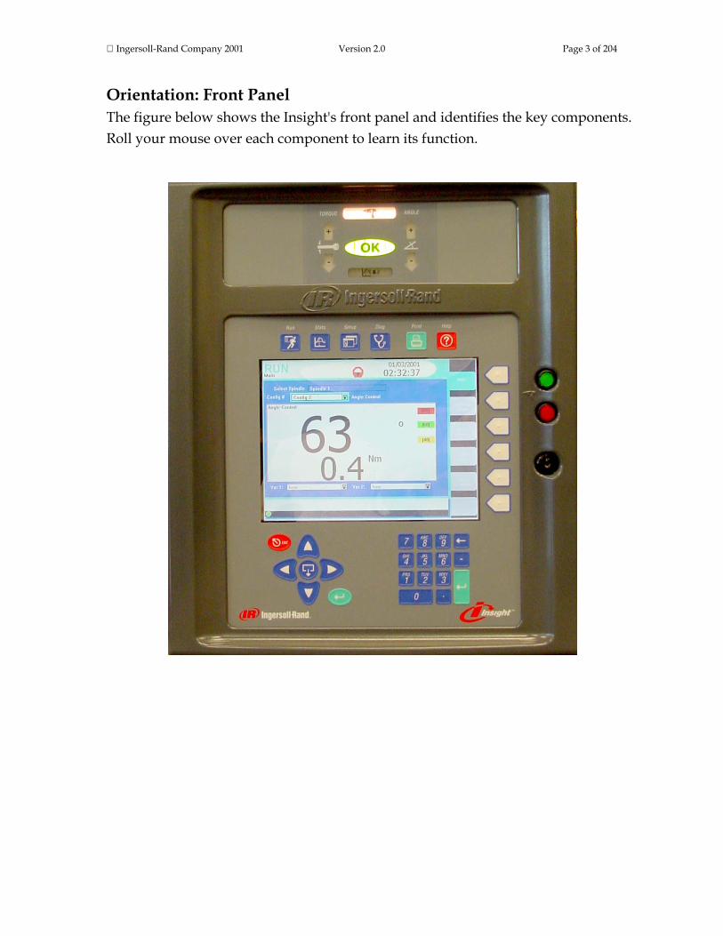
Orientation: Front Panel The figure below shows the Insight's front panel and identifies the key components. Roll your mouse over each component to learn its function.

Ingersoll-Rand Company 2001 Version 2.0 Page 4 of 204
Screen Element Description Graphics Display Screen A full-color display for text and graphics.
Main Menu Keys These keys bring up the main menu screen for the labeled function.
Sub-Menu Keys These keys access sub-menus for each Main Menu Key. The sub-menus are different for each Main Menu.
Numeric Keypad These keys are used to enter alphanumeric data into Insight.
Navigation Keypad These arrow keys are used to navigate on the screen.
Expand Key This key is called the Expand key. It allows selected elements on the graphics display screen to expand, revealing additional options or values. Only the elements that can be expanded display this symbol.
Enter Key After selecting a parameter or entering a value, pressing either Enter Key enters that information into the Insight.
Escape Key This key allows the user to cancel certain operations.
Status Lights Various lights and lighted arrows illuminate during fastening operations to indicate whether the fastening was within specification.
Spindle Power Switch The red button disconnects power to the fastening tools attached to the Insight; the green button supplies power to these tools.
Cabinet Lockout A key lock to prevent access to the internal components.
Some of these front panel components require more explanation than is contained in the roll-overs above. Click on the links below for complete information, or continue your tour and these topics will be introduced later.
How to Use the Navigation Keypad
Entering Data Using the Numeric Keypad Understanding the Status Lights
This is the end of the Components on the Front Panel section. To continue your tour click below or click on another topic at the left.

Ingersoll-Rand Company 2001 Version 2.0 Page 5 of 204
Components on the Side Panels The figures below show the Insight's right-side and left-side panels, and identify important components. Roll your mouse over the components with red highlights to learn their function. Left Side Right Side

Ingersoll-Rand Company 2001 Version 2.0 Page 6 of 204
Screen Element Description
Main Power Switch A rotary switch. The power is off when the rotating handle pointer points to the front of the Insight. The power is on when the pointer points up. This switch can be locked or tagged out for service.
Insight Label This permanent label lists important information, including electrical circuit ratings and the Insight Model Number and Serial Number (also called a Date Code).
Mounting Bracket For mounting the Insight to walls, rails, etc.
Spindle 1 Connector The Insight's Spindle 1 attaches here. Ingersoll-Rand spindles have a 23-pin, twist-to-lock connector at the end of their cables that plug in here.
Spindle 2 Connector The Insight's Spindle 2 attaches here. If you have a single spindle model, this connector will be absent.
Floppy Disk Drive (Optional) Optional Floppy disk drive for saving /loading Data and software
Terminal Blocks The cables that carry the input and output signals for the spindle(s) attach here.
Parallel Port For attaching a parallel printer.
Serial Ports For attaching a PC or other serial device.
Ethernet Port For attaching an Ethernet computer network cable.
Data Bus Port Optional port for attaching field bus cards.
Modem Port For attaching a phone line for an optional modem.
Power Cord Receptacle The AC power cord (supplied) plugs in here.
Some of these screen elements require more explanation than is contained in the roll-overs above. Click on the links below for complete information, or continue your tour and these topics will be introduced later.
The Pin-Out for the Terminal Blocks Attaching Peripheral Devices The Pin-Out for the Insight's Serial Port
This is the end of the Components on the Side Panels section. To continue your tour click below or click on another topic at the left. Understanding the Status Lights The graphic below shows the Status Lights located on the front panel above the graphics display screen. These LEDs give the operator an instant visual indication of the quality of every tightening operation. Operators may use these various lights to assess the quality of each fastening, and may want to take specific actions based

Ingersoll-Rand Company 2001 Version 2.0 Page 7 of 204
on these indicators. Roll your mouse over the components with red highlights to learn their function. Each Ingersoll-Rand hand-held spindle also has an indicating light on the tool itself that mimics the Status Lights. If the fastening is within specification the tool light will be green. If either the torque or angle value is too high the tool light will be red, if either value is too low the tool light will be yellow.
Screen Element Description
SPINDLE The Spindle 1 or Spindle 2 light will illuminate white, indicating power is being applied to that spindle.
OK The green OK LED will light if the tightening met all of the programmed specifications and requirements.
Torque Lights red if the torque exceeded the specified upper limit.
Torque Lights yellow if the torque was less than the specified minimum value.
Angle Lights red if the angle exceeded the specified upper limit.
Angle Lights yellow if the angle was less than the specified minimum value.
STATS ALARM Lights if the statistical parameters are outside the user-defined limits.
The explanations in the roll-overs above are largely self-explanatory, with the exception of STATS ALARM. For complete information on STATS ALARM click on the link below, or continue your tour and this topic will be introduced later.

Ingersoll-Rand Company 2001 Version 2.0 Page 8 of 204
Setting the Statistics Alarm This is the end of the Understanding the Status Lights section. To continue your tour click below, or click on another topic at the left. How to Use the Navigation Keypad The arrows on the navigation keypad (see graphic below) are used to navigate among the screen elements (buttons, drop boxes, etc.). When you have navigated to a screen element it becomes highlighted with a border. Pressing the Enter key on the navigation keypad (or the one on the numeric keypad) will activate the highlighted screen element. (The action is similar to clicking on a screen button with a computer mouse.)
If you activate or enter a screen element with the Expand symbol on it, that symbol indicates the element can be opened to reveal additional options. Pressing the Expand symbol located in the center of the navigation keypad will open the element and display the options. You can then use the arrow keys to move to the option you want, and then select that option by pressing Enter. The Escape key on the navigation keypad can be used to cancel certain operations. This is the end of the How to Use the Navigation Keypad section. To continue your tour click below, or click on another topic at the left.

Ingersoll-Rand Company 2001 Version 2.0 Page 9 of 204
How to Enter Data Using the Numeric Keypad If you have navigated to a screen element that requires data entry (a data entry box), you will use the numeric keypad to enter information (numbers and/or letters). As shown on the graphic below, selected number keys are also labeled with three letters.
Most of the data entry boxes are for entering numeric data only. Simply enter a numeric value directly from the keyboard. If you make a mistake, press the Backspace key (←) to delete the number. When the correct number is displayed, press either Enter key to enter the value. There are a few data entry boxes that allow you to enter alphanumeric information. For example, there are boxes that allow you to enter a plant name (such as Assembly Plant #2) or an assembly configuration name (Right Door). When you are in these data entry boxes the Insight system automatically puts the numeric keypad in alphanumeric mode. In that mode, pressing a numeric key once will enter the first letter on that key, twice the second letter, three times the third letter, four times the number. When you have the correct character displayed, pressing the right arrow key places that character and moves the cursor to the next data entry space within that box. If you want to enter a space, simply press the right arrow key a second time. If you make a mistake, press Backspace (←) to delete the character. When the correct character string is displayed, press either Enter key to enter that value. This is the end of the How to Enter Data Using the Numeric Keypad section. To continue your tour click below, or click on another topic at the left.

Ingersoll-Rand Company 2001 Version 2.0 Page 10 of 204
Understanding the Six Insight Menus There are six Main Menu Keys above the graphics display screen. Four of these are the principal menu keys (Run, Statistics, Set-up, and Diagnostics), that, when pressed, bring up an initial menu screen and a series of sub-menu options. Once learned, Insight navigation is quick. Pressing one menu key and one sub-menu key will take you to any Insight function. The function of each Main Menu Key is described below.
Run The Run menu displays fastening data (torque, angle, and
many other parameters) in tabular form after each fastening operation. Actual torque vs. angle fastening curves can also be displayed. In addition, Run mode provides access to other useful data, such as statistical summaries and historical logs of fastening performance. Run screens provide quick, view-only access to information.
Statistics The Statistics menu displays raw fastening data as well as
statistical analyses. Individual tightening curves can be overlaid for comparison and analysis. The operator can display statistical trends and set alarm functions to identify off-normal fastening statistics.
Set-up The Set-up menu allows for programming the fastening
strategies. A quick setup feature allows rapid programming of standard strategies, while advanced setup offers customized strategies. Set-up also controls numerous basic system parameters, such as selecting the display language, setting torque measurement units, and creating operator access passwords.
Diagnostics The Diagnostics menu controls Insight's self-diagnosis
programs. Insight continually looks for operating problems or component failures. It alerts the operator to problems with the tools or with the controller electronics, and can even suggest root causes and corrective action.
Print The Print menu allows for printing a variety of fixed-format
reports on fastening data, statistics, system settings, and so on.

Ingersoll-Rand Company 2001 Version 2.0 Page 11 of 204
Help The Help menu allows the user to access operating help and
displays the information on the graphics display screen. This is the end of the Understanding the Six Insight Menus section. To continue your tour click below, or click on another topic at the left. Understanding the Graphics Display Screen Layout The Graphics Display Screen has six distinct sections or regions, as shown in the graphic below. Roll your mouse over the screen elements that have red highlights to learn their function.

Ingersoll-Rand Company 2001 Version 2.0 Page 12 of 204
Screen Element Description
Header
The Header shows the Insight's current menu and sub-menu, the date and the time, and whether the system is locked or unlocked (the padlock icon). When the system is locked, the padlock icon is closed and red, when unlocked it is open and green. If unlocked, the password level to which the system is unlocked (there are four levels) is also shown.
Wizard Box The Wizard Box displays short descriptions of whatever is highlighted on the screen, or may provide abbreviated instructions for performing a task.
Sub-Menu Names The sub-menus are different for each of the four principal Main Menu keys (Run, Statistics, Set-up, and Diagnostics).
Main Window The Main Window displays all the parameter selection and data entry fields, and may display tabular or graphical tightening data.
Message Box The Message Box summarizes system status and provides warnings and alarms.
Insight Controller Software Status Box
This bar shows the status of the Insight Controller Software (ICS), the optional software that allows the Insight to communicate over a network. If the light in the box is green, the ICS is connected and operational. Depending on the ICS's communication status, the box may display additional information
This is the end of the Understanding the Graphics Display Screen Layout section. To continue your tour click below, or click on another topic at the left. Understanding the Screen Elements All the different menu screens that can appear on the Insight graphics display panel have certain design elements in common. These design elements, called screen elements, appear in the Main Window section of the display, and are shown in the graphics below. Click on each element to learn its function. In actual operation, the user will use the arrows on the directional keypad to navigate the cursor to the individual screen elements. A dark border around the screen element indicates that the cursor is at that screen element.

Ingersoll-Rand Company 2001 Version 2.0 Page 13 of 204
Screen Element Description
Button To click on a button, navigate to it with the arrow keys and press either Enter key.
Drop Box
Drop boxes are indicated by the Expand symbol. To open a drop box, navigate to it with the arrow keys and press the Expand key. Use the arrow keys to move to the desired option, and then press either Enter key to select that option.
Data Entry Box Navigate to a data entry box with the arrow keys and then use the numeric keypad to enter a value. Press either Enter key to place that value in the data entry box.
Check Box Navigate to a check box using the arrow keys. Press either Enter key to check or uncheck the box.
Display Box
Display boxes contain view-only information. Navigate to the display box with the arrow keys and press Expand to enter the box. Use the arrow keys to scroll up/down and left/right. Press Expand again to move the cursor out of the display box
This is the end of the Understanding the Screen Elements section and the end of the Insight Orientation topic. To continue your tour click below, or click on another topic at the left.

Ingersoll-Rand Company 2001 Version 2.0 Page 14 of 204
Insight Installation Installation This section describes how to mount the Insight controller, attach fastening tools (spindles) to the controller, attach printers and other peripheral devices, and startup the system. Click on one of the links to go directly to the topic, or click on the arrows below to continue your tour.
Mounting the Insight Enclosure Attaching Spindles Attaching Peripheral Devices Initial Startup
Mounting the Insight Enclosure Bolt the Insight controller enclosure to a suitable surface near the assembly area using the mounting brackets on the back of the enclosure. For a drawing of the Insight system with dimensions, information on bracket hole spacing, recommended mounting bolts, door opening clearances, and other mounting information, click on Insight Dimensional Drawings. Make sure the mounting is stable, secure, and level.
Attach the Insight enclosure to a structure capable of safely supporting its total weight. (Click here for the weight of the enclosure.) Failure to follow installation instructions properly can result in structure collapse and personal injury.
Make sure the Main Power Switch is in the Off position. In the United States, the Insight controller enclosure comes pre-wired with a power cord and the appropriate plug. Insight systems sold internationally have a power cord with a pigtail, and the user must supply the correct connector. Review the electrical circuit information on the Insight's label (on the right-side panel) and in the specifications table. Verify that your electrical circuit meets the Insight's power requirements and circuit breaker ratings. Plug the AC power cord into an appropriate receptacle.

Ingersoll-Rand Company 2001 Version 2.0 Page 15 of 204
It is the user's responsibility to ensure that the Insight controller is installed and wired by a qualified electrician.
This is the end of the Mounting the Insight Enclosure section. To continue your tour click below, or click on another topic at the left.
Attaching Spindles Attach your Ingersoll-Rand spindles (or powerheads) on the right side of the Insight enclosure. (If you are not sure where they attach, click here.) At the end of each spindle's cable is a twist-to-lock 23-pin connector. In general, any spindle may be plugged into any spindle connector. However, the user may have preferred locations for the spindles based on the fastening applications. Plug each tool(s) into the appropriate connector and lock it in place. If you wish to change your Insight Controller from handheld operation to machine mount mode, click here for more information. There should be a tool(s) attached to each connector. If no tool is present, when the unit is powered up, no power will be delivered to the empty connector. This is a safety feature. The Insight interprets the lack of a tool as a tool with a possible ground fault, and does not energize that circuit. Note: It is not necessary to have a tool attached to the Insight IC in order to program it. If a connector is left empty and a tool is added at a later time, turn the Insight Main Power Switch off, wait five seconds, and turn it back on. Or press the red button on the front panel Spindle Power Switch, wait five seconds, then press the green button. Either process will allow the Insight to recognize the new tool. This is the end of the Attaching Spindles section. To continue your tour click below, or click on another topic at the left.
Ingersoll-Rand Company 2001 Version 2.0 Page 16 of 204
Attaching Peripheral Devices This section provides instructions for attaching various devices to the Insight IC Fastening System with Graphics Display. Click on a link below to review that topic, or continue your tour and these topics will be introduced in the order shown.
Socket Tray Connection and Setup External Configuration Switch Connection and Setup How to Test a Socket Tray or Configuration Switch Light Box Connection and Setup Parallel Printer Connection and Setup Serial Printer Connection and Setup Computer Connection and Setup via the Serial Port PLC Connection and Setup Modem Connection Ethernet Connection Field Bus Card Connection
Socket Tray Connection and Setup
1. Connect the socket tray to the Insight controller’s terminal blocks (located on the controller's left side) with the appropriate accessory cable.
2. Attach a tool to the Insight controller and turn the controller on using the rotary switch.
3. Push the green Start button on the Spindle Power Switch on the front panel to power the Motor Controller and the tool.
4. Go to the Set-up menu and the Spindle Initialization sub-menu screen.
5. If your socket tray has more than eight positions, go to Step 6 below. If your socket tray has eight or less positions, go to Step 7 below.
6. Select External Binary from the Config. Select drop box and then go to Step 8.
7. Select External Discrete from the Config. Select drop box and then go to Step 8.
Ingersoll-Rand Company 2001 Version 2.0 Page 17 of 204
8. You have now completed setup of your socket tray. Click here for information on how to test your socket tray.
External Configuration Switch Connection and Setup
1. Connect the configuration switch to the Insight controller’s terminal blocks (located on the controller's left side) with the appropriate accessory cable.
2. Attach a tool to the Insight controller and turn the controller on using the rotary switch.
3. Push the green Start button on the Spindle Power Switch on the front panel to power the Motor Controller and the tool.
4. Go to the Set-up menu and the Spindle Initialization sub-menu screen.
5. If your configuration switch has more than eight positions, go to Step 6 below. If your socket tray has eight or less positions, go to Step 7 below.
6. Select External Binary from the Config. Select drop box and then go to Step 8.
7. Select External Discrete from the Config. Select drop box and then go to Step 8.
8. You have now completed setup of your configuration switch. Click here for information on how to test your configuration switch.
How to Test a Socket Tray or Configuration Switch
1. After you have connected and setup the device, go to the Diagnostics menu and the Discrete Inputs sub-menu screen.
2. As you lift the sockets or move the switch you should see the appropriate indicators light up on the screen, indicating activity on the configuration lines. (Note: if you selected External Binary in the Config Select drop box on the Set-Up menu’s Spindle Initialization screen, then the first four configuration lines will indicate the binary encoded number for the configuration selection, with 0000 indicating configuration 1 is selected.)

Ingersoll-Rand Company 2001 Version 2.0 Page 18 of 204
Light Box Connection and Setup
1. Connect the light box to the Insight controller’s terminal blocks (located on the controller's left side) on the controller's left side with the appropriate accessory cable.
2. Attach a tool to the Insight controller and turn it on using the controller’s rotary switch.
3. Push the green Start button on the Spindle Power Switch on the front panel to power the Motor Controller and the tool.
4. If you are going to connect a socket tray to the light box, connect it with the appropriate cable and follow the procedure to install the socket tray starting from Step 4. Click here for that procedure.
5. You have now completed your light box setup. Parallel Printer Connection and Setup
1. Connect your printer via a standard parallel printer cable to the 25-pin port labeled with a printer icon located on the left side of the Insight controller.
2. Turn on the printer and make sure it is on line.
3. Print a test report to ensure the printer is setup correctly. Serial Printer Connection and Setup
1. Connect your printer via a standard 9-pin serial cable to a serial port located on the left side of the Insight controller labeled I0I0I. Click here to see the correct port.
2. Go to the Set-up menu’s System Initialization sub-menu screen and select the desired COM port from the Data Port drop box.
3. On the same screen, check that the settings for Baud Rate, Parity, # of Stop Bits, and Bits Per Character match those settings on the serial printer. Change the settings as necessary.
4. Turn on the printer and make sure it is on line.
5. Print a test report to ensure the printer is setup correctly. If you get odd characters on the printout, verify the settings in Step 3 match those settings on the printer.

Ingersoll-Rand Company 2001 Version 2.0 Page 19 of 204
Computer Connection and Setup via the Serial Port
Note: To connect a computer to the Insight controller you will need Insight Controller Software (ICS) or a terminal software package, such as Windows 95, 98, or 2000 HyperTerminal, or Win 3.1 Terminal.
1. Connect your computer via a Null Modem 9-pin serial cable to the port located on the left side of the Insight controller labeled I0I0I. Click here to see the correct port.
2. Go to the Set-up menu’s System Initialization sub-menu screen and select the desired COM port from the Data Port drop box.
3. On the same screen, check that the settings for Baud Rate, Parity, # of Stop Bits, and Bits Per Character match those settings on the terminal software package of your computer. Change the settings as necessary.
4. Print a test report to ensure the computer is setup correctly. If you get odd characters on the printout, verify the settings in Step 3 match those settings on the computer.
PLC Connection and Setup
Note: All connections to a PLC are made via the Insight’s terminal blocks, except data collection. Data collection is done via the serial ports. For data collection, click here and follow the procedures for setup via the serial port. To connect a PLC to the terminal blocks, see the procedure below.
Through the terminal blocks, a PLC can send and receive a variety of outputs to and from the Insight controller. (Click here to see a terminal block pinout.) It is important to always use a shielded cable for all PLC signals to the Insight controller, and the shielded cable should only be terminated at one end. All inputs and outputs are activated/received in the same way, as discussed below.
Activating an Input All input signals operate at 24VDC. The Return for the 24V signal must be
connected to COM IN for each input bank. It is recommended that you use the internal 24VDC located at the terminals marked 24VDC OUT +/-. Switch the 24VDC back to the desired input signal (FORWARD, REVERSE, FREE SPEED etc).
To use the internal 24VDC, you must connect a jumper wire from 24VDC
OUT (-) to COM IN of the input bank. The to activate an input you would then provide a contact closure between the desired inputs signals and 24VDC OUT
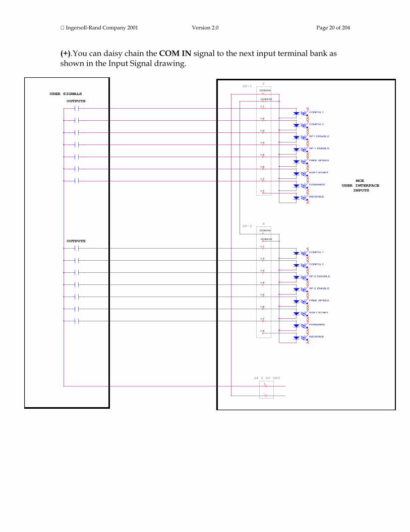
Ingersoll-Rand Company 2001 Version 2.0 Page 20 of 204
(+).You can daisy chain the COM IN signal to the next input terminal bank as shown in the Input Signal drawing.
I-6
I-3
I-7
COM IN
COM IN
I-4
I-5
I-1
I-2
I-1
I-5
COM IN
I-6
I-4
I-2
COM IN
I-3
I-7
I-8
I-7
+
-
MCE
INPUTS
USER SIGNALS
OUTPUTS
OUTPUTS
SP-12
4SP-2
24 V DC OUT
USER INTERFACE
SP-1 ENABLE.
CONFIG 1.
FREE SPEED.
CONFIG 2.
SP1 DISABLE.
SOFT START.
FORWARD.
CONFIG 1.
FREE SPEED.
SOFT START.
CONFIG 2.
FORWARD.
SP-2 DISABLE.
SP-2 ENABLE.
REVERSE.
REVERSE.

Ingersoll-Rand Company 2001 Version 2.0 Page 21 of 204
Receiving an Output All output signals operate at 24VDC. The 24V signal and its return must
be connected to the terminal blocks labeled +/- 24VDC EXT on each output connector bank. It is recommended that you use an external 24VDC supply. The output signals will be switched back to you from the appropriate output signal (ACCEPT, REJECT, HIGH TORQUE etc). See the Output Signal drawing. You can daisy chain the +/- 24VDC to the next output bank.
O-3
0-2
O-4
O-5
O-6
0-7
0-8
+
-
O-1
MCE
USER SIGNALS
INPUTS
OUTPUTS24 V DC EXT
SP-1
1
�+
-
.
ACCEPT
�+
-
.
REJECT
�+
-
.
HIGH TORQUE
�+
-
.
LOW TORQUE
�+
-
.
CYCLE COMP
�+
-
.
LOW ANGLE
�+
-
.
HIGH ANGLE
�+
-
.
RESERVE
24VDC
RTN

Ingersoll-Rand Company 2001 Version 2.0 Page 22 of 204
Modem Connection and Setup This capability will be in a future release of the Insight IC. Ethernet Connection This capability will be in a future release of the Insight IC. Field Bus Card Connection The Insight IC can connect to a field bus network using either a Profibus card or a Devicenet card. Make sure one of these field bus cards is installed in your system then click on the link below. Scroll to the section on the appropriate card for setup instructions.
Communications Protocol Setup
This is the end of the Attaching Peripheral Devices section. To continue your tour click below or click on another topic at the left. Initial Startup Before starting the Insight IC Fastening System with Graphics Display for the first time, you must go through the following checklist and verify that all of the steps have been completed. Click on the links below for specific instructions. If in doubt about any aspect of this checklist, contact Ingersoll-Rand.
• The Insight controller enclosure is vertical, level, and securely mounted.
• For every spindle location that will be used there is a spindle attached to that location in the connector panel (located on the controller's right side), and each spindle connector is locked down.
• If the Insight is equipped for attaching external devices (printers, computers, etc.), the proper devices have been attached to the appropriate ports in the connector panel (located on the controller's left side).
• The main enclosure is closed and locked.
• The AC power cord is plugged into a properly rated electrical circuit. Once the above checklist is verified, you are ready to power-up the Insight IC Fastening System with Graphics Display. Turn the Main Power Switch to On. This switch sends power to the internal Motor Controllers, the graphics display, and the keypads, but does not send power to the spindle(s) or powerhead(s).

Ingersoll-Rand Company 2001 Version 2.0 Page 23 of 204
Push the green button on the Spindle Power Switch located on the front panel. The SPINDLE LED on the Status Lights will illuminate, indicating power is now going to the spindle(s). The Run Main screen will be displayed on the graphics display panel, indicating the startup was successful and the Insight IC is ready to operate. When you want to turn the entire Insight system on or off use the Main Power Switch. After turning the system off, wait at least five seconds before turning it on again. When you want to turn only the spindles on and off use the Spindle Power Switch. This is the end of Initial Startup section and the entire Insight Installation topic. To continue your tour click below or click on another topic at the left. Quick Start Quick Start: Be Operational in Minutes The goal of this section is to have your Insight IC Fastening System with Graphics Display up and running in just a few minutes. Before proceeding with the steps below, make sure the Insight controller is properly mounted, a spindle has been attached to each spindle connector, and you have completed the steps described in Initial Startup.
1. Turn the Main Power Switch to On.
2. Push the green button on the Spindle Power Switch to power the spindle(s) and initialize the internal controller. (You can follow this sequence from the messages displayed on the screen.) The Run Main screen will be displayed indicating the start-up was successful.
3. Press the Set-up Main Menu Key.
4. Press the Spindle Initialization Sub-Menu Key. When the screen appears the cursor will be on the Select Spindle drop box. (If your Insight is a one-spindle model you will not have a Select Spindle drop box; skip Step 5.)
5. If you want to use Spindle 1, proceed to Step 6. If you want to use Spindle 2, press the Expand key, use the arrow keys to scroll to Spindle 2, and press Enter.

Ingersoll-Rand Company 2001 Version 2.0 Page 24 of 204
6. Press the arrow keys until the cursor is on the drop box labeled Tool Type.
7. Press the Expand key and scroll down the list until the cursor is on the model number of the spindle attached, press Enter. When you select a spindle the Insight searches its internal database and finds the generic values for two important tool parameters—Transducer Range and Angle Constant (or Angle Scale Constant)—and inserts these values in the appropriate boxes on the screen.
8. Check the values in the Transducer Range and Angle Constant boxes with those same values on the spindle's calibration label to verify they are the same or close. (This serves as a check that you have selected the correct spindle model number.) You may enter your tool’s specific values into these boxes, or—if the values are identical or close—you may leave the generic values. (If you do change the Transducer Range value, make sure the torque units—usually Newton-meters—are the same on the calibration label and the screen box.)
9. Press the Quick Set-Up Sub-Menu Key.
10. Use the arrow keys and navigate to the Strategy drop box.
11. Press the Expand key and scroll down the list until the cursor is on the type of fastening strategy desired, press Enter.
12. Use the arrow keys and navigate to the data entry box where you will enter the fastening target value. For torque control go to the Torque Target box; for angle control go to the Angle Target box; for yield control go to the Yield Point % box.
13. Using the numeric keypad, enter a target value appropriate for the strategy selected, and for your particular fastening operation.
14. Review the default values in the on-screen boxes and edit as desired.
15. Press the Run Main Menu Key (when the dialogue box appears, press Yes if you want to save the configuration you have just programmed).
Congratulations! You have just programmed your Insight IC Fastening System with Graphics Display, and you are ready to begin fastening operations. This is the end of Quick Start: Be Operational in Minutes section. To continue your tour click below, or click on another topic at the left.

Ingersoll-Rand Company 2001 Version 2.0 Page 25 of 204
Menu Screens Menus and Sub-Menus: Overview As explained in the Insight Orientation section above, the Insight IC Fastening System with Graphics Display has six Main Menu Keys located just above the graphics display screen on the front panel. To review the main menu functions, click on a link (Run, Statistics, Set-up, Diagnostics, Print, Help). Pressing a Main Menu Key brings up the first screen for that menu item on the graphics display panel. Each main menu item will also have up to six sub-menus. The sub-menu screens are displayed by pressing one of the Sub-Menu Keys located to the right of the graphics display panel. It is these menu and sub-menu screens that are used to setup and program the Insight, review and display fastening data, print out statistical analysis of fastening operations, and control all of the many other operations that the Insight performs. In this section we describe the main menu and the sub-menu screens in detail. At this point you can continue your tour for an explanation of each main menu and its sub-menus in turn, or you can click on a link below to go directly to a particular menu series. The main menu explanations are presented in the left-to-right order of the Main Menu Keys on the Insight front panel (beginning with Run and ending with Help). If this is your first time through this manual you may want to begin your tour with the Set-up menu, since these are the screens you will use to set basic fastening parameters and strategies. Of course, at any time you can scroll through the detailed Table of Contents at the left and click on a topic to access that specific information.
The Run Menus The Statistics Menus The Set-up Menus The Diagnostics Menus The Print Menus The Help Menus

Ingersoll-Rand Company 2001 Version 2.0 Page 26 of 204
Menu Screens: The Run Menus The Run menu allows the user to view fastening parameters and fastener tightening curves in real time during fastening operations. It also gives the user quick access to statistics, fastening logs, and other useful information. This section discusses each of the Run sub-menu screens. The thumbnails above the links below will help you recognize each screen's layout. To go to a discussion of a Run screen click on the link, or continue your tour and these topics will be introduced in the sequence shown.
Run Main Screen Tightening Curves Screen Stats Summary Screen Cycle Log Screen View Parameters Screen
Run Menu: Run Main Screen This screen displays the actual torque and angle values following each fastening. Below is a typical Run Main screen. Click on the screen elements that have red highlights to learn their function.

Ingersoll-Rand Company 2001 Version 2.0 Page 27 of 204
Screen Element Description
Spindle
Use this drop box to select the spindle for which the tightening data will display. You can display the data for Spindle 1, Spindle 2, for both spindles, or for a powerhead. This drop box will not be present if your Insight is a one-spindle model.
Configuration ID
Automatically displayed beneath the Spindle drop box are the Configuration name, the Configuration number, and the Strategy name for the tightening sequence. If it is a multi-step sequence, the Strategy name is that of the last step. When the Config Select drop box on the Spindle Initialization screen is set to "Internal," this drop box sets which configuration the controller will run.
Tightening Values
The large primary number is the torque value for the last tightening, unless the strategy is angle control (in which case it will be the angle value). The smaller secondary number is the angle value, unless the strategy is angle control (in which case it will be the torque value). Note that both the primary and secondary numbers show either a degree symbol or torque units, making it clear which parameter is displayed.
Limit Values
The three numbers to the right of the primary number are (from top to bottom) the high limit, the target value, and the low limit for the primary parameter. The values displayed are those that were programmed during either the Quick Set-up or Advanced Set-up operations for the selected configuration.
Var. 1 This drop box has a list of tightening variables. The user can select one of these variables to display here during each fastening operation. Below is the description of the tightening variables.

Ingersoll-Rand Company 2001 Version 2.0 Page 28 of 204
Var. 2 This drop box has a list of tightening variables. The user can select one of these variables to display here during each fastening operation. Below is the description of the tightening variables.
Message Box The Message Box summarizes system status and provides warnings and alarms.
Insight Controller Software Status Box
This bar shows the status of the Insight Controller Software (ICS), the optional software that allows the Insight to communicate over a network. If the light in the box is green, the ICS is connected and operational. Depending on the ICS's communication status, the box may display additional information
The tightening variables that the user can display in the Var. 1 and Var. 2 drop boxes (see graphic above) are listed below. Each drop box can display only one variable. To select the desired tightening variable, first navigate to the drop box using the arrow keys. Press the Expand key to display the variables, then use the arrow keys to scroll through the list to the desired variable (or enter the number of the variable), and finally press the Enter key to select the variable. The user can change the variable displayed at any time.
Variable Explanation
None No variable will be displayed
#OK % Number and % of PASS tightenings
# Rejects % Number and % of FAIL tightenings
# Rejects Hi\Lo The number of fastenings that were over \ under the tightening limits
Sigma/6 sigma Standard deviation / six times the standard deviation (used for statistical calcs)
CAM A statistical parameter to evaluate tightening performance; for details click here
Capability A statistical parameter to evaluate tightening performance; for details click here
Cp/CpK A statistical parameter to evaluate tightening performance; for details click here
Cycle # Each fastening is one cycle, and is incremented by one to give it a unique number
Cycle Time The elapsed time for the fastening cycle
Gang Count For a multiple fastener process, the current count and total count (e.g., 1 of 4)
Mean/Range The average value and the max. less the min. value for the control parameter

Ingersoll-Rand Company 2001 Version 2.0 Page 29 of 204
Meanshift The difference between the mean value and the control point value
Peak Current The maximum current the tool drew during the fastening cycle
Barcode Displays the bar code value attached to the cycle
Pk. Drag Torque Peak drag torque reached (only displays for a drag torque strategy)
Peak Prevailing Torque Displays the peak prevailing torque value (only for a prevailing torque strategy)
Prevailing Torque Slope Displays the slope value of the prevailing torque curve (only for a prevailing torque strategy)
Peak Cut-in Torque Displays the peak cut-in torque for the prevailing torque and drag torque strategies
Avg Prevailing Torque The average prevailing torque (only displays for a prevailing torque strategy
Avg. Drag Torque The average torque over the target inspection angle.
Seating Angle Degrees of angle rotated when seating torque is reached
Torque at Seat Peak torque at seating point
Min. Drag Torque Minimum drag torque reached (only displays for a drag torque strategy)
Tool Type Displays the tool model number.
Shutdown Code A code created after every cycle; for details click here
This is the end of the Run Menu: Run Main Screen section. To continue your tour click below, or click on another topic at the left. Run Menu: Tightening Curves Screen This screen is used to display tightening curves in real time during fastening operations. It allows the user to view tightening curves, freeze the curves for closer inspection, and display selected parameters. Below is a typical Tightening Curves screen. Click on the screen elements that have red highlights to learn their function.

Ingersoll-Rand Company 2001 Version 2.0 Page 30 of 204
The information this screen displays depends upon how the Run Main screen is set. Above the main window the spindle number, configuration number, configuration name, and strategy name will be displayed, as described under Run Menu: Run Main Screen.
Screen Element Description
Select Spindle
Use this drop box to select the spindle for which the tightening data will display. You can display the data for Spindle 1, Spindle 2, for both spindles, or for a powerhead. This drop box will not be present if your Insight is a one-spindle model
Select Plot Type Use this drop box to select the plot type: Torque vs. Angle, Torque vs. Time, or Current vs. Time.
Freeze This button freezes the tightening curve for study. Fastening will continue but the new curves do not display. The frozen curve remains until the user presses the button again, or until the user exists this screen.
Ingersoll-Rand Company 2001 Version 2.0 Page 31 of 204
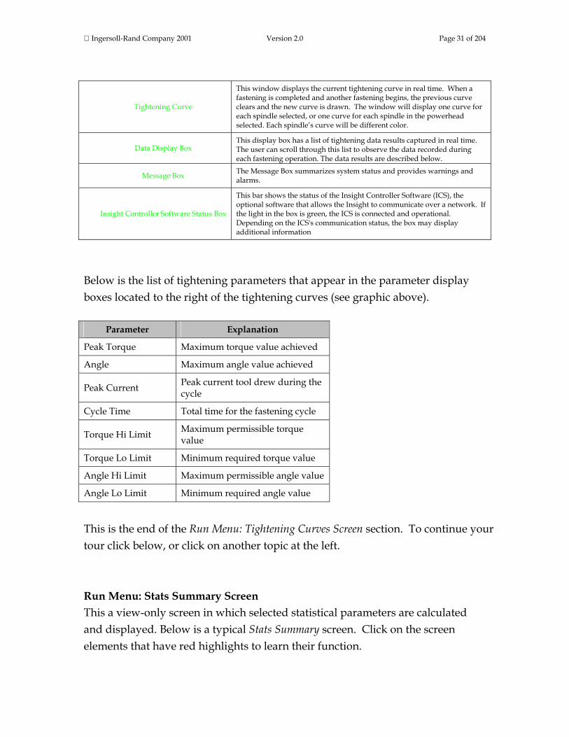
Tightening Curve
This window displays the current tightening curve in real time. When a fastening is completed and another fastening begins, the previous curve clears and the new curve is drawn. The window will display one curve for each spindle selected, or one curve for each spindle in the powerhead selected. Each spindle’s curve will be different color.
Data Display Box This display box has a list of tightening data results captured in real time. The user can scroll through this list to observe the data recorded during each fastening operation. The data results are described below.
Message Box The Message Box summarizes system status and provides warnings and alarms.
Insight Controller Software Status Box
This bar shows the status of the Insight Controller Software (ICS), the optional software that allows the Insight to communicate over a network. If the light in the box is green, the ICS is connected and operational. Depending on the ICS's communication status, the box may display additional information
Below is the list of tightening parameters that appear in the parameter display boxes located to the right of the tightening curves (see graphic above).
Parameter Explanation
Peak Torque Maximum torque value achieved
Angle Maximum angle value achieved
Peak Current Peak current tool drew during the cycle
Cycle Time Total time for the fastening cycle
Torque Hi Limit Maximum permissible torque value
Torque Lo Limit Minimum required torque value
Angle Hi Limit Maximum permissible angle value
Angle Lo Limit Minimum required angle value
This is the end of the Run Menu: Tightening Curves Screen section. To continue your tour click below, or click on another topic at the left. Run Menu: Stats Summary Screen This a view-only screen in which selected statistical parameters are calculated and displayed. Below is a typical Stats Summary screen. Click on the screen elements that have red highlights to learn their function.

Ingersoll-Rand Company 2001 Version 2.0 Page 32 of 204
Screen Element Description
Select Spindle Use this drop box to select the spindle or powerhead for which the tightening data will display. This drop box will not be present if your Insight is a one-spindle model.
Select Configuration Use this drop box to select the tightening configuration (by number and name) whose statistics summary will display.
Main Window Show tables of the Population and Sample tightening statistics. Below is additional information on these tables.
Message Box The Message Box summarizes system status and provides warnings and alarms.
Insight Controller Software Status Box
This bar shows the status of the Insight Controller Software (ICS), the optional software that allows the Insight to communicate over a network. If the light in the box is green, the ICS is connected and operational. Depending on the ICS's communication status, the box may display additional information
This screen’s main window displays information for the one spindle or powerhead selected. The left-hand table lists the statistics for the total number of fastenings performed for that configuration since the statistics were last reset (called the Population statistics), and the right-hand table lists the statistics for

Ingersoll-Rand Company 2001 Version 2.0 Page 33 of 204
the fastening sample size (called the Sample statistics). (The number of fastenings in the Sample statistics is set in the Statistics Alarm Set-Up screen within the Statistics menu. To go to that screen now, click here.) If a spindle has been selected, the statistical parameters displayed on the Stats Summary screen are:
Parameter Explanation
Target The target value for this tightening configuration
X-Bar The average (mean) value for the control parameter
Meanshift The difference between the mean value and the control point value
Range The maximum less the minimum value for the control parameter
Max Value The maximum value for the control parameter
Min Value The minimum value for the control parameter
# for Sigma The number of cycles used for the standard deviation calculation
Sigma Standard deviation (used for statistical calculations)
6 Sigma Six times the standard deviation (used for statistical calculations)
Capability A statistical parameter used to evaluate tightening performance; for details click here
Cp A statistical parameter used to evaluate tightening performance; for details click here
CpK A statistical parameter used to evaluate tightening performance; for details click here
CAM A statistical parameter used to evaluate tightening performance; for details click here
# Hi Rejects Number of fastenings that failed for control parameter being too high
# Lo Rejects Number of fastenings that failed for control parameter being too low

Ingersoll-Rand Company 2001 Version 2.0 Page 34 of 204
If a powerhead has been selected, the statistical parameters displayed on the Stats Summary screen are:
Parameter Explanation
Total number of powerhead cycles The number of powerhead fastenings performed
Sample stats size The number of cycles used to calculate the fastening statistics
# of powerhead OK Number of PASS tightenings
% of powerhead OK Percent of PASS tightenings
# of powerhead reject Number of FAIL tightenings
% of powerhead reject Percent of FAIL tightenings
# of rejects for each spindle in the powerhead Number of FAIL tightenings for each spindle
% of rejects for each spindle in the powerhead Percent of FAIL tightenings for each spindle
Last cycle time for the powerhead The elapsed time for the last fastening cycle
This is the end of the Run Menu: Stats Summary Screen section. To continue your tour click below, or click on another topic at the left. Run Menu: Cycle Log Screen This is a view-only screen that displays various tightening parameters monitored, recorded, and stored in memory for all readings in the current fastening series, up to a maximum of 5,000. This screen displays the most recent 1,000 cycles. To view the rest go to the Statistics menu's Cycle Log screen. Below is a typical Run menu Cycle Log screen. Click on the screen elements that have red highlights to learn their function.

Ingersoll-Rand Company 2001 Version 2.0 Page 35 of 204
Screen Element Description
Spindle Use this drop box to select the spindle or powerhead for which the cycle log data will display. This drop box will not be present if your Insight is a one-spindle model.
Clear Cycle Data This button will clear the cycle log data table for the displayed spindle.
Reset Cycle Number This button will reset the cycle log number back to 1 for the displayed spindle.
Main Window This window displays the cycle log summary table. Below is additional information on the parameters displayed.
Message Box The Message Box summarizes system status and provides warnings and alarms.
Insight Controller Software Status Box
This bar shows the status of the Insight Controller Software (ICS), the optional software that allows the Insight to communicate over a network. If the light in the box is green, the ICS is connected and operational. Depending on the ICS's communication status, the box may display additional information
Note that the Cycle Log main window is a display box. The user can enter this box to scroll through the table by first navigating to the Cycle Log main window with the arrow keys. Then press the Expand key to activate the scroll function, and use the arrow keys to scroll through the table.

Ingersoll-Rand Company 2001 Version 2.0 Page 36 of 204
The Cycle Log table will always display the following parameters:
Parameter Explanation
Cycle # The unique number for the cycle
Powerhead # Powerhead number for the data collected
Spindle # Spindle number for the data collected
Config # The fastening configuration used (01 through 32)
Step # Step number for the data collected
Date The date the fastening was made
Time The time the fastening was made
Barcode The bar code value for the cycle (only if bar code functionality is turned on) Cycle result PASS or FAIL
Torque Measured torque value
Torque Result Whether measured torque value was PASS, HIGH, or LOW
Angle Measured angle value
Angle Result Whether measured torque angle was PASS, HIGH, or LOW
The following parameters may or may not appear in the Cycle Log window, depending on how the End of Run Filter was set. (The End of Run Filter is set in the System Initialization screen within the Set-up menu. Click here to go to the End of Run Filter.)
Parameter Explanation
Shutdown Code A code created after every cycle; for details click here
Peak Current The maximum current the tool drew during the fastening cycle
Cycle Time The elapsed time for the fastening cycle
Peak Slope Peak slope of the torque vs. angle curve
Final Slope Final slope of the torque vs. angle curve
Prevailing Torque Slope The slope of the tightening curve for a prevailing torque strategy
Peak Cut-in Torque The peak cut-in torque for the prevailing torque and drag torque strategies
Peak Prevailing Torque The maximum torque measured during the prevailing torque phase of a prevailing torque strategy
Average Prevailing Torque The average torque measured during the prevailing torque phase

Ingersoll-Rand Company 2001 Version 2.0 Page 37 of 204
of a prevailing torque strategy
Angle at Seat The degrees of angle rotated when seating torque is reached
Torque at Seat The measured torque value when seating torque is reached
Peak Drag torque The maximum torque measured during the drag torque phase of a drag torque strategy
Average Drag Torque The average torque measured during the drag torque phase of a drag torque strategy
Minimum Drag Torque The minimum torque measured during the drag torque phase of a drag torque strategy
This is the end of the Run Menu: Cycle Log Screen section. To continue your tour click below, or click on another topic at the left. Run Menu: View Parameters Screen This is a view-only screen that displays a tabular summary of all of the parameters the user has set for all of the steps in a fastening configuration. Below is a typical View Parameters screen. Click on the screen elements that have red highlights to learn their function.

Ingersoll-Rand Company 2001 Version 2.0 Page 38 of 204
Screen Element Description
Spindle Use this drop box to select the spindle or powerhead whose parameters will display. This drop box will not be present if your Insight is a one-spindle model.
Select Configuration Use this drop box to select the tightening configuration (by number and name) whose parameters will display.
Programmed Steps Use this drop box to display all of the steps programmed for the spindle and configuration selected.
Step Parameters This display box shows all the parameters and their values for the step selected in the Programmed Steps drop box.
Message Box The Message Box summarizes system status and provides warnings and alarms.
Insight Controller Software Status Box
This bar shows the status of the Insight Controller Software (ICS), the optional software that allows the Insight to communicate over a network. If the light in the box is green, the ICS is connected and operational. Depending on the ICS's communication status, the box may display additional information

Ingersoll-Rand Company 2001 Version 2.0 Page 39 of 204
Note that the View Parameters main window consists of two display boxes. The user can enter the Programmed Steps drop box by navigating to it with the arrow keys and then pressing the Expand key. Then select a fastening step by using the arrow keys to scroll through the table until the desired step is highlighted, then press Enter. The parameters and their values for the fastening step selected are then shown in the Step Parameters display box on the right side of the main window. If there are parameters in the Step Parameters display box with which you are not familiar, they are described in detail in the Parameters section. This is the end of the Run Menu: View Parameters Screen section and the end of Menu Screens: The Run Menus topic. To continue your tour click below, or click on another topic at the left. Menu Screens: The Statistics Menus The Statistics menu allows the user to view a variety of statistical data on completed fastenings. The user can view actual fastening parameters as well as statistical measurements, and can compare them to desired (target) values. Individual tightening curves can be displayed and overlaid for comparison. The user can set alarm values to alert the operator to fastenings that do not meet the required statistical parameters. Finally, cycle data are exportable to PCs or other devices for additional analysis. This section discusses each of the Statistics sub-menu screens. The thumbnails above the links below will help you recognize each screen's layout. To go to a discussion of a Statistics screen click on the link, or continue your tour and these topics will be introduced in the sequence shown. The thumbnails above each menu screen link below will help you recognize their look and screen layout.
Summary Screen Export Cycle Log Screen Tightening Curves Screen Cycle Log Screen Stats Alarm Screen

Ingersoll-Rand Company 2001 Version 2.0 Page 40 of 204
Statistics Menu: Summary Screen This screen displays a large number of fastening statistics for either one or two spindles. If you have a single spindle Insight IC system, the Statistics Summary screen is as shown below. Note that on the left side it displays the statistical data for all the fastenings performed since the statistics were last reset (the Population statistics) and on the right side the statistics for a subset of the cycle (the Sample statistics). Click on the screen elements that have red highlights to learn their function.

Ingersoll-Rand Company 2001 Version 2.0 Page 41 of 204
Screen Element Description
Select Config Use this drop box to select the tightening configuration (by number and name) whose statistics will display.
Clear All
Press this button to clear both the population and the sample statistics. Note that this clears the data for statistical analysis only; the raw data remain in memory and may be retrieved using the Statistics Cycle Log screen.
Clear Sample Press this button to clear only the sample statistics. Note that this clears the data for statistical analysis only; the raw data remain in memory and may be retrieved using the Statistics Cycle Log screen.
Populations Statistics The statistics for the entire fastening population are displayed here.
Sample Statistics The statistics for the sample subset of the population are displayed here.
Message Box The Message Box summarizes system status and provides warnings and alarms.
Insight Controller Software Status Box
This bar shows the status of the Insight Controller Software (ICS), the optional software that allows the Insight to communicate over a network. If the light in the box is green, the ICS is connected and operational. Depending on the ICS's communication status, the box may display additional information
Below is a typical Statistics Summary screen for a two-spindle Insight IC system. Note that both the left side and right side of the screen have boxes for selecting a spindle and a configuration, and a box for displaying statistics. The statistics boxes display either the Population statistics or the Sample statistics. Click on the screen elements that have red highlights to learn their function.

Ingersoll-Rand Company 2001 Version 2.0 Page 42 of 204
Screen Element Description
Select Spindle Use this drop box to select the spindle for which the tightening data will display. You can display the data for Spindle 1, Spindle 2, for both spindles, or for a powerhead.
Clear All
Press this button to clear both the population and the sample statistics. Note that this clears the data for statistical analysis only; the raw data remain in memory and may be retrieved using the Statistics Cycle Log screen.
Clear Sample Press this button to clear only the sample statistics. Note that this clears the data for statistical analysis only; the raw data remain in memory and may be retrieved using the Statistics Cycle Log screen.
Stats from Use this drop box to select the entire fastening population or a sample of that population.
Select Config Use this drop box to select the tightening configuration (by number and name) whose statistics will display.

Ingersoll-Rand Company 2001 Version 2.0 Page 43 of 204
Main Window The statistical data display here. Below is additional information on the
parameters displayed.
Message Box The Message Box summarizes system status and provides warnings and alarms.
Insight Controller Software Status Box
This bar shows the status of the Insight Controller Software (ICS), the optional software that allows the Insight to communicate over a network. If the light in the box is green, the ICS is connected and operational. Depending on the ICS's communication status, the box may display additional information
For both single spindle and dual spindle Insight IC controllers, the following statistical parameters display on the Statistics Summary screen if a spindle is selected. These same statistical parameters display for both the fastening population and the fastening sample.
Parameter Explanation
Target The target value for this tightening configuration
X-Bar The average (mean) value for the control parameter
Meanshift The difference between the mean value and the control point value
Range The maximum less the minimum value for the control parameter
Max Value The maximum value for the control parameter
Min Value The minimum value for the control parameter
Sigma Standard deviation (used for statistical calculations)
6 Sigma Six times the standard deviation (used for statistical calculations)
# for Sigma The number of cycles used for the standard deviation calculation
Cp A statistical parameter used to evaluate tightening performance; for details click here
CpK A statistical parameter used to evaluate tightening performance; for details click here
Capability A statistical parameter used to evaluate tightening performance; for details click here
CAM A statistical parameter used to evaluate tightening performance; for details click here
# Rej. Total number of fastenings that failed to meet the fastening criteria
# Hi Rejects Number of fastenings that failed for control parameter being too high
# Lo Rejects Number of fastenings that failed for control parameter being too low
# H/W rej. Number of equipment-related (hardware) fastening failures

Ingersoll-Rand Company 2001 Version 2.0 Page 44 of 204
However, if a powerhead (rather than a spindle) is selected, a different set of parameters is displayed, as shown below.
Parameter Explanation
Total number of powerhead cycles The number of powerhead fastenings performed
Sample stats size The number of cycles used to calculate the fastening statistics
# of powerhead OK Number of PASS tightenings
% of powerhead OK Percent of PASS tightenings
# of powerhead reject Number of FAIL tightenings
%of powerhead reject Percent of FAIL tightenings
# of rejects for each spindle in the powerhead Number of FAIL tightenings for each spindle
% of rejects for each spindle in the powerhead Percent of FAIL tightenings for each spindle
Last cycle time for the powerhead The elapsed time for the last fastening cycle
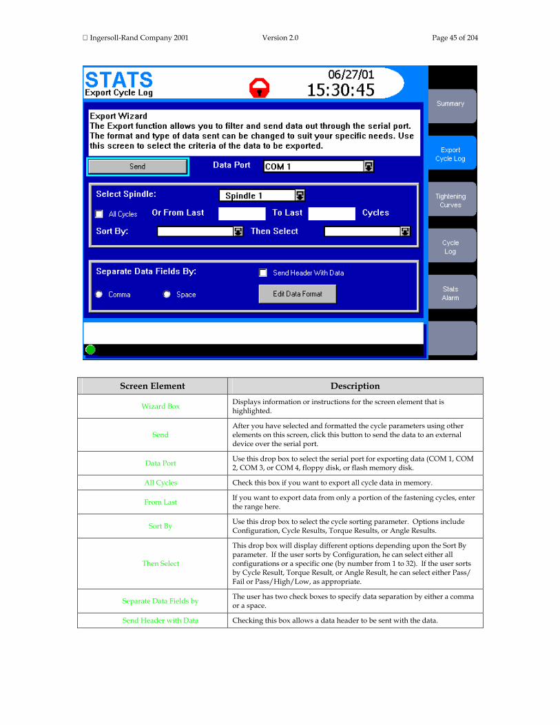
This is the end of the Statistics Menu: Summary Screen section. To continue your tour click below, or click on another topic at the left. Statistics Menu: Export Screen Using the Statistics Export screen, the user can select, filter, and format cycle data and export that data, via the serial port, to a PC or other device. Below is a typical Statistics Export screen. Click on the screen elements that have red highlights to learn their function.
Ingersoll-Rand Company 2001 Version 2.0 Page 45 of 204
Screen Element Description
Wizard Box Displays information or instructions for the screen element that is highlighted.
Send After you have selected and formatted the cycle parameters using other elements on this screen, click this button to send the data to an external device over the serial port.
Data Port Use this drop box to select the serial port for exporting data (COM 1, COM 2, COM 3, or COM 4, floppy disk, or flash memory disk.
All Cycles Check this box if you want to export all cycle data in memory.
From Last If you want to export data from only a portion of the fastening cycles, enter the range here.
Sort By Use this drop box to select the cycle sorting parameter. Options include Configuration, Cycle Results, Torque Results, or Angle Results.
Then Select
This drop box will display different options depending upon the Sort By parameter. If the user sorts by Configuration, he can select either all configurations or a specific one (by number from 1 to 32). If the user sorts by Cycle Result, Torque Result, or Angle Result, he can select either Pass/ Fail or Pass/High/Low, as appropriate.
Separate Data Fields by The user has two check boxes to specify data separation by either a comma or a space.
Send Header with Data Checking this box allows a data header to be sent with the data.

Ingersoll-Rand Company 2001 Version 2.0 Page 46 of 204
Edit Data Format Clicking this button brings up a second Export screen to select the specific
tightening data for export. Below is additional information on this screen.
Message Box The Message Box summarizes system status and provides warnings and alarms.
Insight Controller Software Status Box
This bar shows the status of the Insight Controller Software (ICS), the optional software that allows the Insight to communicate over a network. If the light in the box is green, the ICS is connected and operational. Depending on the ICS's communication status, the box may display additional information
Clicking on the Edit Data Format button on the screen above brings up the following Export screen.
This second Export screen above lists numerous statistical parameters. As explained in the screen's wizard box, the user can select the specific statistical parameters and their order by entering a sequential number in each parameter box. Entering a zero means that parameter will not be exported. Click on the screen elements that have red highlights to learn their function.

Ingersoll-Rand Company 2001 Version 2.0 Page 47 of 204
Screen Element Description
Make E.O.R. Data Out Same Format Checking this box gives the "End of Run Data Out " serial protocol the same format as the statistics export data.
Make Host Data Out Same Format Checking this box gives the "Host Data Out" serial protocol the same format as the statistics export data.
OK Clicking this button sets the data export order and returns the user to the main Export screen.
Cancel Clicking this button cancels all changes and returns the user to the main Export screen.
The parameters available on this screen are listed below.
Parameter Explanation
Cycle # The unique number for the cycle
Powerhead # Powerhead number for the data collected
Spindle # Spindle number for the data collected
Config # The fastening configuration used (01 through 32)
Step # Step number for the data collected
Date The date the fastening was made
Time The time the fastening was made
Barcode The bar code value for the cycle (only if bar code functionality is turned on)
Cycle result PASS or FAIL
Torque Measured torque value
Torque Result Whether measured torque value was PASS, HIGH, or LOW
Angle Measured angle value
Angle Result Whether measured torque angle was PASS, HIGH, or LOW
Shutdown Code A code created after every cycle; for details click here
Peak Current The maximum current the tool drew during the fastening cycle
Cycle Time The elapsed time for the fastening cycle
Peak Slope Peak slope of the torque vs. angle curve
Final Slope Final slope of the torque vs. angle curve
Prevailing Torque Slope The slope of the tightening curve for a prevailing torque strategy
Peak Cut-in Torque The peak cut-in torque for the prevailing torque and drag torque strategies

Ingersoll-Rand Company 2001 Version 2.0 Page 48 of 204
Peak Prevailing Torque The maximum torque measured during the prevailing torque phase of a prevailing torque strategy
Average Prevailing Torque The average torque measured during the prevailing torque phase of a prevailing torque strategy
Angle at Seat The degrees of angle rotated when seating torque is reached
Torque at Seat The measured torque value when seating torque is reached
Peak Drag torque The maximum torque measured during the drag torque phase of a drag torque strategy
Average Drag Torque The average torque measured during the drag torque phase of a drag torque strategy
Minimum Drag Torque The minimum torque measured during the drag torque phase of a drag torque strategy
This is the end of the Statistics Menu: Export Screen section. To continue your tour click below, or click on another topic at the left. Statistics Menu: Tightening Curves Screen To improve a fastening sequence or to resolve fastening problems, it is often important to understand the tightening curve in detail. With this screen, the user can view tightening curves and zoom in on those curves to analyze them. In addition, important aspects of the curve—such as the number of data points, peak torque value, and so on—are automatically calculated and displayed. Below is a typical Tightening Curves screen. Click on the screen elements that have red highlights to learn their function.

Ingersoll-Rand Company 2001 Version 2.0 Page 49 of 204

Ingersoll-Rand Company 2001 Version 2.0 Page 50 of 204
Screen Element Description
Select Spindle Use this drop box to select the spindle whose tightening curves will be displayed. This drop box will not be present if your Insight is a one-spindle model.
Select Config Use this drop box to select the tightening configuration whose curves will display. The options include configuration 01 through 32.
Select Plot Type Use this drop box to select the plot type: Torque vs. Angle, Torque vs. Time, or Current vs. Time.
Select Capture Type Use this drop box to select which fastening curves will be captured and displayed. Options include Last Cycle, Last Reject, Next Cycle, Next 2 Cycles, … Next 5 Cycles.
Select Plot If you have multiple plots displayed on the screen, use this drop box to select one for analysis. The selected plot becomes a solid line, distinguishing it from the other plots displayed.
Replace Plot Clicking this button replaces the plot selected in the Select Plot drop box with the next valid plot.
Load Master
You may have tightening curves stored in memory that you want to use as a reference or master; a curve against which you can compare other fastenings. Pressing this button brings up a float box that allows you to select one of the stored curves and display it on the screen as the master plot. The button name then toggles to Remove Master, and now pressing it removes the master and displays the previous curve.
Plot Update Pressing this button removes any plots on the screen (except a Master plot) and places new plots on the screen, as determined by the setting in the Select Capture Type drop box.
Zoom In
Clicking this button will zoom in on the tightening curve displayed on the screen. The button name then toggles to Zoom Out, and now clicking it returns the display to normal scale. When zoomed in, use the left and right arrow keys to move along the plot.
Save Master
You may have a particular tightening curve that you want to use as a reference or master; a curve against which you can compare other fastenings. Select the plot you want to save with the Select Plot drop box, then press this button to save it as the Master plot. A float box comes up that allows you to select a location to save the plot.
Full View This button expands the plot window to full screen. Pressing the Close button on the bottom of the expanded screen will return the screen to normal view.
Plot Window The tightening curves you have selected with the buttons and drop boxes above display here. Below is additional information on how to analyze the plot(s) displayed.
Plot Summary Window
This window to the right of the tightening curves lists information about the plots displayed. This includes the Plot Number, the number of data points used to create the plot, the Peak Angle, and the Peak Torque (or Peak Time or Peak Current, depending upon the selection made in the Select Plot Type drop box).
Message Box The Message Box summarizes system status and provides warnings and alarms.
Insight Controller Software Status Box
This bar shows the status of the Insight Controller Software (ICS), the optional software that allows the Insight to communicate over a network. If the light in the box is green, the ICS is connected and operational. Depending on the ICS's communication status, the box may display additional information

Ingersoll-Rand Company 2001 Version 2.0 Page 51 of 204
You can examine in detail the tightening curve displayed in the screen's main window by navigating to the plot window and pressing the Expand key. This allows you to take control of the cross hairs in the plot window. (The cross hairs will appear on the curve selected in the Select Plot drop box.) Use the directional keypad's arrow keys to move the cross hairs to the region of interest on the tightening curve. Note that the numerical values for the curve at the cross hair's location display on the screen. This is the end of the Statistics Menu: Tightening Curves Screen section. To continue your tour click below, or click on another topic at the left. Statistics Menu: Cycle Log Screen This is a view-only screen that displays various tightening parameters that are monitored, recorded, and stored in memory for up to the last 5,000 tightening cycles. This screen functions generally the same as the Cycle Log screen under the Run Menu, but with the added ability to sort data. Below is a typical Cycle Log screen. Click on the screen elements that have red highlights to learn their function.

Ingersoll-Rand Company 2001 Version 2.0 Page 52 of 204
Screen Element Description
Select Spindle Use this drop box to select the spindle or powerhead for which the cycle log data will display. This drop box will not be present if your Insight is a one-spindle model.
Sort By Use this drop box to select the criteria by which the cycle log data display in the screen's main window. The options include: Cycle, Configuration, Cycle Result, Torque Result, and Angle Result.
View By Use this drop box to select which fastening cycles display in the screen's main window. The options here depend on the criteria selected in the Sort By drop box.
Main Window This window displays the cycle log summary table. The row order of the data will vary depending upon the sorting criteria selected in the Sort By drop box. Below is additional information on the parameters displayed.
Message Box The Message Box summarizes system status and provides warnings and alarms.
Insight Controller Software Status Box
This bar shows the status of the Insight Controller Software (ICS), the optional software that allows the Insight to communicate over a network. If the light in the box is green, the ICS is connected and operational. Depending on the ICS's communication status, the box may display additional information
Note that the Cycle Log screen window is a display box. The user can scroll through the table in this window using the arrow keys. The Cycle Log table will always display the following parameters:
Parameter Explanation
Cycle # The unique number for the cycle
Powerhead # Powerhead number for the data collected
Spindle # Spindle number for the data collected
Config # The fastening configuration used (01 through 32)
Step # Step number for the data collected
Date The date the fastening was made
Time The time the fastening was made
Barcode The bar code value for the cycle (only if bar code functionality is turned on) Cycle result PASS or FAIL
Torque Measured torque value
Torque Result Whether measured torque value was PASS, HIGH, or LOW
Angle Measured angle value
Angle Result Whether measured torque angle was PASS, HIGH, or LOW

Ingersoll-Rand Company 2001 Version 2.0 Page 53 of 204
The following parameters may or may not appear in the Cycle Log table, depending on how the End of Run Filter was set. (The End of Run Filter is set in the System Initialization screen within the Set-up menu. Click here to go to the End of Run Filter.)
Parameter Explanation
Shutdown Code A code created after every cycle; for details click here
Peak Current The maximum current the tool drew during the fastening cycle
Cycle Time The elapsed time for the fastening cycle
Peak Slope Peak slope of the torque vs. angle curve
Final Slope Final slope of the torque vs. angle curve
Prevailing Torque Slope The slope of the tightening curve for a prevailing torque strategy
Peak Cut-in Torque The peak cut-in torque for the prevailing torque and drag torque strategies
Peak Prevailing Torque The maximum torque measured during the prevailing torque phase of a prevailing torque strategy
Average Prevailing Torque The average torque measured during the prevailing torque phase of a prevailing torque strategy
Angle at Seat The degrees of angle rotated when seating torque is reached
Torque at Seat The measured torque value when seating torque is reached
Peak Drag torque The maximum torque measured during the drag torque phase of a drag torque strategy
Average Drag Torque The average torque measured during the drag torque phase of a drag torque strategy
Minimum Drag Torque The minimum torque measured during the drag torque phase of a drag torque strategy
This is the end of the Statistics Menu: Cycle Log Screen section. To continue your tour click below, or click on another topic at the left.

Ingersoll-Rand Company 2001 Version 2.0 Page 54 of 204
Statistics Menu: Statistics Alarm Set-Up Screen In many applications it is important to systematically monitor tightening performance using statistical parameters. This screen allows the user to set alarms that will indicate deviations from selected fastening statistics, thereby alerting the Insight operator to a potential quality problem. Below is a typical Statistics Alarm Set-Up screen. Click on the screen elements that have red highlights to learn their function.

Ingersoll-Rand Company 2001 Version 2.0 Page 55 of 204
Screen Element Description
Select Spindle Use this drop box to select the spindle for which the alarms will display. This drop box will not be present if your Insight is a one-spindle model.
Select Config Use this drop box to select the tightening configuration whose statistics alarms will display. The options include configuration 01 through 32.
S.M.A.R.T. Windows Enable
Checking this box enables S.M.A.R.T. (Self-Moving Automatic Range Test) Windows. With this function enabled, Insight calculates and sets certain tightening limits, and warns the user if the limits are exceeded. Below is additional information on this function.
Reset Button Clicking on this button resets and recalculates the S.M.A.R.T. Windows limits. Below is additional information on this function.
Settings Clicking on this button brings up a S.M.A.R.T. Windows screen. Below is a description of this screen.
Values for Stats Use this drop box to select what tightening results are included in your statistical calculation. The options are Good Only, All, or All but hardware faults.
Sample Size Using the numeric keypad, enter a sample size. This will be the number of samples used to calculate the sample statistics.
Main Window This window has two boxes, to set the alarms for both torque and angle. The user can set alarms for all of the statistical parameters listed in these boxes, and can individually turn those alarms on or off. Below is additional information on these alarms.
Message Box The Message Box summarizes system status and provides warnings and alarms.
Insight Controller Software Status Box
This bar shows the status of the Insight Controller Software (ICS), the optional software that allows the Insight to communicate over a network. If the light in the box is green, the ICS is connected and operational. Depending on the ICS's communication status, the box may display additional information

Ingersoll-Rand Company 2001 Version 2.0 Page 56 of 204
S.M.A.R.T. Windows Discussion S.M.A.R.T. stands for Self-Moving Automatic Range Test. Many first-time users of the Insight system, when operating in torque control (or angle control) strategy, set their high and low monitoring limits for the angle (or torque) measurement very loosely. They do this because they have little information on what the actual limits should be. By activating S.M.A.R.T., the Insight controller automatically calculates upper and lower limits based on a sampling of 25 fastenings, and then sets alarms to warn the operator if any fastening exceeds these limits. Specifically, S.M.A.R.T. calculates two values commonly used in statistical process control: the Average Range value (R) and the Mean of the Means value (X). Insight then calculates an upper control limit and a lower control limit for the angle or torque as follows:
Upper control limit = X + 2.66R Lower control limit = X – 2.66R
If the angle or torque value for a fastening is outside these limits, the Stats Alarm light on the Insight's front panel will flash. The S.M.A.R.T. Windows Reset button on the Statistics Alarm Set-Up screen recalculates the S.M.A.R.T. limits. Clicking on this button tells the Insight controller to capture the data from the next 25 fastenings and then recalculate the upper and lower control limits. Clicking on the S.M.A.R.T. Windows Settings button brings up the following screen. Click on the screen elements that have red highlights to learn their function.

Ingersoll-Rand Company 2001 Version 2.0 Page 57 of 204
Screen Element Description
High Limit This box displays the calculated value for the S.M.A.R.T. upper control limit.
Low Limit This box displays the calculated value for the S.M.A.R.T. lower control limit.
Set Limits Clicking this button sets the monitored limits to the calculated limits shown on this screen.
Sensitivity Use this drop box to set the S.M.A.R.T. sensitivity to High or Low. These options are described below.
OK Clicking on this button saves the current S.M.A.R.T. settings and exits this screen.
Cancel Clicking on this button cancels the settings and exits this screen.
Setting the S.M.A.R.T. sensitivity to high or low (see graphic above) has the following effect. When set to High, Insight uses the S.M.A.R.T. limits calculated for the first 25 fastenings to compare subsequent fastenings. This means that any fastening outside these initial control limits will trigger a Stats Alarm light. When set to Low, Insight calculates the S.M.A.R.T. limits based on the most recent 25 fastenings. This means that any gradual drift in the limits (caused by joint component manufacturing variances for example) will not trigger a Stats Alarm light, rather Insight will only alarm when it detects gross deviations from the constantly adjusting control limits. S.M.A.R.T. Windows calculations are independent of user entered torque or angle limits. However, the user can set the monitored tightening limits to the

Ingersoll-Rand Company 2001 Version 2.0 Page 58 of 204
calculated S.M.A.R.T. limit values by navigating to the Set Limits button and pressing Enter. Finally, the user must be aware of the following aspects of the S.M.A.R.T. Windows option.
• S.M.A.R.T. alarms will only occur on tightenings that otherwise pass all their fastening criteria. If Insight indicates a high or low torque or angle fault, the user should investigate the fault source, as it takes precedence over a S.M.A.R.T. alarm.
• The user must separately calculate S.M.A.R.T. control limits for each spindle and each configuration.
• In a multi-step strategy, S.M.A.R.T. control limits will only be available if the final step is either torque control or angle control.
Main Window Statistics Alarms Discussion Using the arrow keys, the user can navigate to the Statistics Alarm Set-Up screen's main window and scroll down through the statistics parameters listed under both Torque and Angle. For each parameter, the user can enter an alarm value using the numeric keypad. Use the check box to the right of each parameter to either turn that alarm on or off. In the main window the user can set alarms for the following statistical parameters for both torque and angle.
Parameter Explanation
Cp A statistical parameter used to evaluate tightening performance; for details click here
CpK A statistical parameter used to evaluate tightening performance; for details click here
6 Sigma Six times the standard deviation (used for statistical calculations)
Capability A statistical parameter used to evaluate tightening performance; for details click here
CAM A statistical parameter used to evaluate tightening performance; for details click here
% Pass The percentage of tightenings that met the fastening criteria
Meanshift The difference between the mean value and the control point value
Range The maximum less the minimum value for the control parameter

Ingersoll-Rand Company 2001 Version 2.0 Page 59 of 204
This is the end of the Statistics Menu: Statistics Alarm Set-Up Screen section and the end of Menu Screens: The Statistics Menus topic. To continue your tour click below, or click on another topic at the left. Menu Screens: The Set-up Menus The Set-up menu and sub-menus are used to program tightening strategies and to set a broad variety of important system parameters. Both basic tightening strategies as well as advanced, customized strategies are created in the Set-up menu. In addition to strategies, you can use the Set-up menu to set many basic system parameters, such as date and time, display language, measurement units, and communications protocols. The Set-up menu is also used to create passwords for controlling access to Insight's software and data records. Before you can use Set-up menus to program the Insight for fastening, you must tell the software what kind of spindle is attached to the system in each spindle location. Some Ingersoll-Rand tools have an embedded Smart Chip that communicates with the Insight IC controller, telling it what kind of tool is attached. If you do not have a Smart Chip tool, you will have to enter certain basic parameters. In addition, if you want to measure torque in units other than the default value of N-m (Newton-meters), you must specify those units. To perform these preliminary operations go to the Spindle Initialization Menu Screen. If you forget to specify what kind of spindle is attached, you will be prompted by the Insight IC system and directed to the correct screen. This section has an overview of the Set-up menu and a discussion of each of the function's six sub-menu screens. The thumbnails above the links below will help you recognize each screen's layout. To go to a discussion of a Set-up screen click on the link, or continue your tour and these topics will be introduced in the sequence shown. The thumbnails above each menu screen link will help you recognize their look and screen layout.
Set-up Menu Overview Quick Set-up Menu Screen

Ingersoll-Rand Company 2001 Version 2.0 Page 60 of 204
Advanced Set-up Menu Screen System Initialization Menu Screen Spindle Initialization Menu Screen Password and Powerhead Settings Parameter Transfer and Smart Chip
Set-up Menu: Quick Set-up Screen This menu screen is used to get you up and running quickly. Many simple fastening operations can be set up from this screen. These include single-step torque control, angle control, or yield control fastening strategies. (These and all other Insight fastening strategies are briefly explained under Fastening Fundamentals.) Only basic fastening parameters are displayed with this screen. If a more complex, multi-step strategy is needed, or to get access to all possible programming parameters, proceed to the Advanced Set-up Menu Screen. The Quick Set-up screen allows you to set key parameters (torque, angle, spindle speed, etc.) for your tightening strategy. You may pre-program up to 32 separate tightening operations per spindle (called Configurations). The parameters displayed on the screen will vary, depending upon the fastening strategy selected. The Quick Set-up screen is shown below. This is the Quick Set-up screen for a torque control tightening strategy. Click on the screen elements that have red highlights to learn their function.
NOTE: If you are not familiar with this screen, the explanations will make more sense if you follow the order indicated by the numbers on the screen elements (1 Select Spindle, 2 Config, 3 Strategy, etc.) Also, notice that near the top of the screen is the Quick Set-up Wizard Box. During actual Insight operation, as you navigate to each screen element a brief explanation of that parameter—as well as any special instructions—is displayed in the Wizard Box. Also, as you set various parameters a summary of the strategy and the parameter set points appears in a Status Box in the lower half of the screen.
To see the Quick Set-up screen for an angle control or a yield control strategy click on the links below, or continue your tour and these topics will be introduced in the sequence shown.
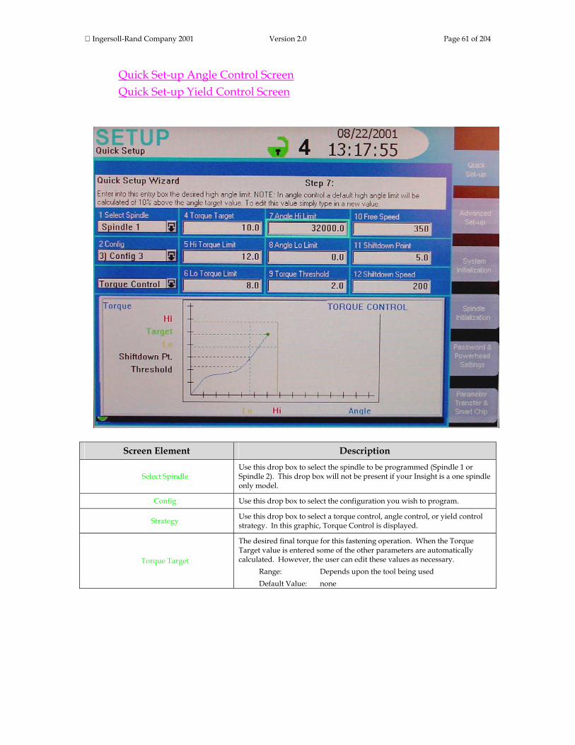
Ingersoll-Rand Company 2001 Version 2.0 Page 61 of 204
Quick Set-up Angle Control Screen Quick Set-up Yield Control Screen
Screen Element Description
Select Spindle Use this drop box to select the spindle to be programmed (Spindle 1 or Spindle 2). This drop box will not be present if your Insight is a one spindle only model.
Config Use this drop box to select the configuration you wish to program.
Strategy Use this drop box to select a torque control, angle control, or yield control strategy. In this graphic, Torque Control is displayed.
Torque Target
The desired final torque for this fastening operation. When the Torque Target value is entered some of the other parameters are automatically calculated. However, the user can edit these values as necessary. Range: Depends upon the tool being used Default Value: none

Ingersoll-Rand Company 2001 Version 2.0 Page 62 of 204
Torque Hi Limit The highest permissible final torque. Range: Depends upon the tool being used Default Value: Torque Target + 20%
Torque Lo Limit The lowest permissible final torque. Range: Depends upon the tool being used Default Value: Torque Target - 20%
Angle Hi Limit The maximum angle through which the fastener may turn. Range: 0 - 32000 Default Value: 32000
Angle Lo Limit The minimum angle through which the fastener must turn. Range: 0 - 32000 Default Value: 0
Torque Threshold The starting point for measuring angle. Range: Depends upon the tool being used Default Value: 20% of Target Torque
Free Speed The maximum speed the tool will run during tightening. Range: Depends upon the tool being used Default Value: 90% of the tool's full free speed
Shiftdown Point
The point during the final stage of tightening at which the tool shifts to a lower speed to improve accuracy. Range: Depends upon the tool being used Default Value: 50% of Target Torque
Shiftdown Speed The tool's speed during the shiftdown phase. Range: Depends upon the tool being used Default Value: 30% of the tool's full free speed
Window The table in the lower part of the window is a summary of the programmed configurations for the spindle selected. The user can scroll through this listing and can also select a configuration.
Below is the Quick Set-up screen for an angle control tightening strategy. Click on the screen elements that have red highlights to learn their function.
NOTE: If you are not familiar with this screen, the explanations will make more sense if you follow the order indicated by the numbers on the screen elements (1 Select Spindle, 2 Config, 3 Strategy, etc.) Also, notice that near the top of the screen is the Quick Set-up Wizard Box. During actual Insight operation, as you navigate to each screen element a brief explanation of that parameter—as well as any special instructions—is displayed in the Wizard Box. Also, as you set various parameters a summary of the strategy and the parameter set points appears in a Status Box in the lower half of the screen.

Ingersoll-Rand Company 2001 Version 2.0 Page 63 of 204
Screen Element Description
Select Spindle Use this drop box to select the spindle to be programmed (Spindle 1 or Spindle 2) This drop box will not be present if your Insight is a one spindle only model.
Config Use this drop box to select the configuration you wish to program.
Strategy Use this drop box to select a torque control, angle control, or yield control strategy. In this graphic, Angle Control is displayed.
Angle Target
The desired angle (in degrees) through which the fastener should turn for this fastening operation. Range: 0 - 32000 Default Value: none
Angle Hi Limit The highest permissible degree of rotation. Range: 0 - 32000 Default Value: Angle Target + 10%
Angle Lo Limit The lowest permissible degree of rotation. Range: 0 - 32000 Default Value: Angle Target - 10%
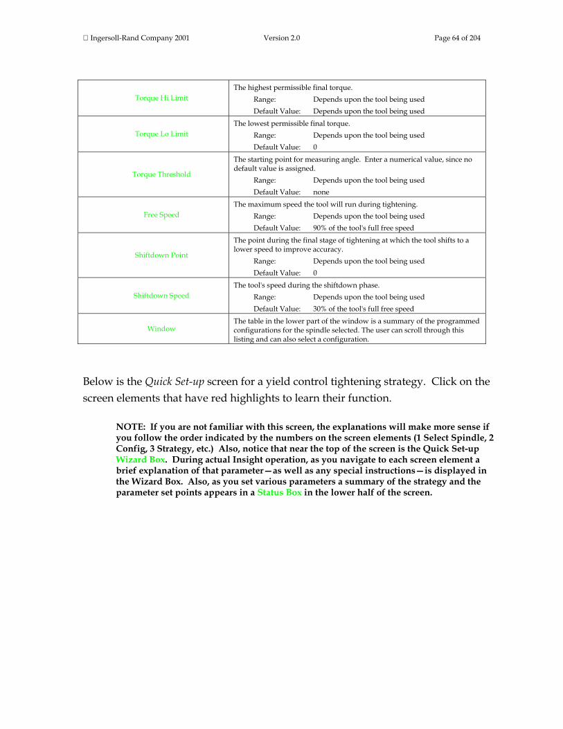
Ingersoll-Rand Company 2001 Version 2.0 Page 64 of 204
Torque Hi Limit The highest permissible final torque. Range: Depends upon the tool being used Default Value: Depends upon the tool being used
Torque Lo Limit The lowest permissible final torque. Range: Depends upon the tool being used Default Value: 0
Torque Threshold
The starting point for measuring angle. Enter a numerical value, since no default value is assigned. Range: Depends upon the tool being used Default Value: none
Free Speed The maximum speed the tool will run during tightening. Range: Depends upon the tool being used Default Value: 90% of the tool's full free speed
Shiftdown Point
The point during the final stage of tightening at which the tool shifts to a lower speed to improve accuracy. Range: Depends upon the tool being used Default Value: 0
Shiftdown Speed The tool's speed during the shiftdown phase. Range: Depends upon the tool being used Default Value: 30% of the tool's full free speed
Window The table in the lower part of the window is a summary of the programmed configurations for the spindle selected. The user can scroll through this listing and can also select a configuration.
Below is the Quick Set-up screen for a yield control tightening strategy. Click on the screen elements that have red highlights to learn their function.
NOTE: If you are not familiar with this screen, the explanations will make more sense if you follow the order indicated by the numbers on the screen elements (1 Select Spindle, 2 Config, 3 Strategy, etc.) Also, notice that near the top of the screen is the Quick Set-up Wizard Box. During actual Insight operation, as you navigate to each screen element a brief explanation of that parameter—as well as any special instructions—is displayed in the Wizard Box. Also, as you set various parameters a summary of the strategy and the parameter set points appears in a Status Box in the lower half of the screen.
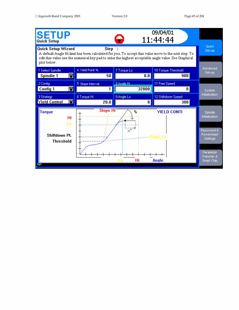
Ingersoll-Rand Company 2001 Version 2.0 Page 65 of 204

Ingersoll-Rand Company 2001 Version 2.0 Page 66 of 204
Screen Element Description
Select Spindle Use this drop box to select the spindle to be programmed (Spindle 1 or Spindle 2). This drop box will not be present if your Insight is a one spindle only model.
Config Use this drop box to select the configuration you wish to program.
Strategy Use this drop box to select a torque control, angle control, or yield control strategy. In this graphic, Yield Control is displayed.
Yield Point %
The percent decrease in the slope value for the torque vs. angle curve that signifies the onset of yield. Range: 20% - 80% Default Value: none
Slope Interval Sets the interval over which the reference slope will be measured. Range: 0 – 10 Default Value: 0
Torque Hi
The highest permissible torque value. Enter a numerical value, since no default value is assigned. Range: Depends upon the tool being used Default Value: none
Torque Lo
The lowest permissible torque value. Enter a numerical value, since no default value is assigned. Range: Depends upon the tool being used Default Value: none
Angle Hi
The maximum angle through which the fastener may turn. Enter a numerical value, since no default value is assigned. Range: 0 - 32000 Default Value: 0
Angle Lo
The minimum angle through which the fastener must turn. Enter a numerical value, since no default value is assigned. Range: 0 - 32000 Default Value: 0
Torque Threshold
The starting point for measuring angle. Enter a numerical value, since no default value is assigned. Range: Depends upon the tool being used Default Value: 0

Ingersoll-Rand Company 2001 Version 2.0 Page 67 of 204
Free Speed The maximum speed the tool will run during tightening. Range: Depends upon the tool being used Default Value: 90% of the tool's full free speed
Shiftdown Point
The point during the final stage of tightening at which the tool shifts to a lower speed to improve accuracy. Range: Depends upon the tool being used Default Value: 0
Window The table in the lower part of the window is a summary of the programmed configurations for the spindle selected. The user can scroll through this listing and can also select a configuration.
This is the end of the Set-up Menu: Quick Set-up Screen section. To continue your tour click below, or click on another topic at the left.
Set-up Menu: Advanced Set-up Screen Introduction to Advanced Set-up The Advanced Set-up Menu Screen allows you to set a very broad range of tightening parameters. This screen is used if a multi-step fastening strategy is required, one more complex than the simple torque control, angle control, or yield control strategies offered under the Quick Set-up Menu Screen. Advanced Set-up may also be used if you want to use one of these three basic strategies, but want to be able to adjust all the possible parameters for the strategy. Advanced Set-up also gives you access to all of Insight's other, more complex, tightening strategies, as summarized in Fastening Fundamentals. Finally, Advanced Set-up allows you to combine these strategies into a series of up to a total of 128 separate and sequential steps, allowing you to create complex and specialized fastening schemes tailored to your unique assembly requirements. If you are already familiar with Advanced Set-up and how to adjust fastening parameters, click on the fastening strategy links below to go to the topics of interest. Otherwise scroll down and we will introduce the basic elements of the Advanced Set-up screen.
Advanced Set-up Strategy Boxes Advanced Set-up Tips Engage Parameters
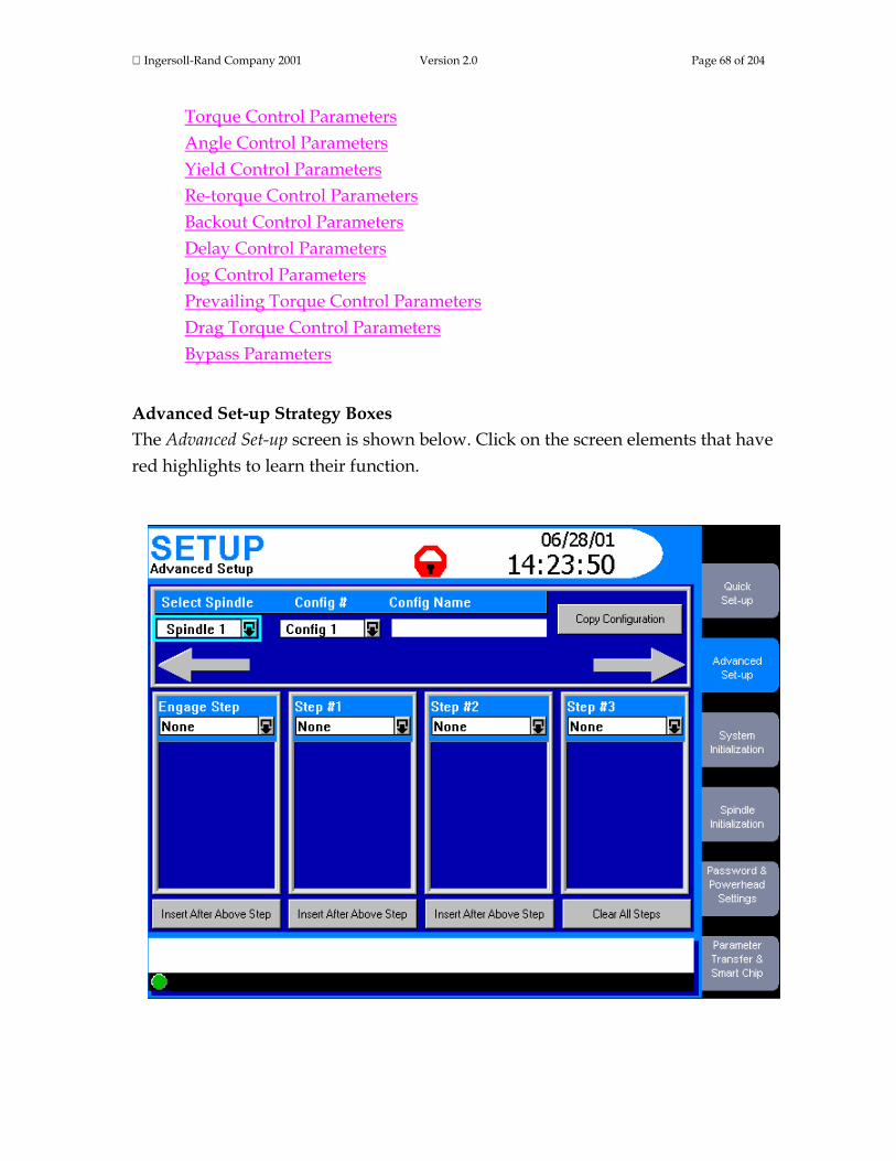
Ingersoll-Rand Company 2001 Version 2.0 Page 68 of 204
Torque Control Parameters Angle Control Parameters Yield Control Parameters Re-torque Control Parameters Backout Control Parameters Delay Control Parameters Jog Control Parameters Prevailing Torque Control Parameters Drag Torque Control Parameters Bypass Parameters
Advanced Set-up Strategy Boxes The Advanced Set-up screen is shown below. Click on the screen elements that have red highlights to learn their function.

Ingersoll-Rand Company 2001 Version 2.0 Page 69 of 204
Screen Element Description
Select Spindle Use this drop box to select Spindle 1 or Spindle 2. This drop box will not be present if your Insight is a one-spindle model.
Config #
If you setting up a new fastening strategy you can select a new Configuration Number that will distinguish this tightening strategy from all others. If you enter a number that has been previously programmed with a fastening strategy, that strategy's parameters will be displayed. Range: 01 – 32 Default Value: Configuration displayed on the Run Main screen
Config Name
You may assign a convenient name to the Configuration # using the alphanumeric keypad (such as Left Door, Part 81B). If a name already exists it will be shown. The name is limited to 14 characters. Note: You must press the Expand key before entering the name.
Copy Configuration
Often an existing fastening configuration will be reused, either as-is or with slight modifications. Rather than re-entering the entire configuration, you can use the Copy Configuration button. Pressing this button allows you to copy the configuration currently displayed to the spindle and configuration you select.
Arrow Keys These arrows light up if there are additional steps available before or after the steps displayed. Use the arrow keys on the navigation to scroll left or right.
Step #n Box You use this drop box to select the strategy desired for each step. More information on the Step #n Boxes is presented below.
Insert After Above Step When pressed, this button inserts an empty step to the right of the current step, shifting all subsequent steps one step to the right.
Clear All Steps Pressing this button clears all the steps for the Configuration # listed.
Note in the graphic below that there are four drop boxes, one labeled Engage and the others labeled Step 1 through Step 3. Recall that there are actually 128 possible steps that can be programmed (shared among the 32 possible configurations). By combining various tightening strategies you program into these drop boxes—each of which can be highly customized—you can create complex fastening sequences tailored to your assembly operations. For every Step #n drop box, whichever strategy you select for that step will bring up a list of parameters inside the box that you can set and adjust. Click on the drop boxes in the graphic below to learn about the fastening strategy steps. If you are not familiar with certain strategies they are explained in Fastening Fundamentals.

Ingersoll-Rand Company 2001 Version 2.0 Page 70 of 204
Screen Element Description
Engage Step When you open this drop box you can only select Engage parameters. These parameters help you ensure that the tool engages the fastener correctly.
Step #1 When you open this drop box you can select from a series of available strategies. Sometimes the options available for any Step #n depend upon the strategy selected for the previous step.
Step #2 When you open this drop box you can select from a series of available strategies. Sometimes the options available for any Step #n depend upon the strategy selected for the previous step.
Step #3 When you open this drop box you can select from a series of available strategies. Sometimes the options available for any Step #n depend upon the strategy selected for the previous step.
Step Parameter Window A series of user-adjustable parameters are displayed here. The specific parameters displayed depend upon the strategy selected in this Step.
The first drop box is unique because it always displays the Engage parameters. The sections below describe the Engage parameter and the parameters for the other tightening strategies. Some of the parameters are required (must be specified) while others are optional. As you navigate to each parameter, Insight displays whether it is required or optional.

Ingersoll-Rand Company 2001 Version 2.0 Page 71 of 204
In some instances, the strategy you select for one step will dictate the possible strategies that will be displayed in the next step. The Insight software manages all these variables. You do not have to worry about these options; merely select the strategy you need from the list displayed. This completes the Advanced Set-up Strategy Boxes section. To continue your tour click below or click on another topic at the left. Advanced Set-up Tips In this section we discuss several topics that are essential to understanding the Advanced Set-up function. Strategy Sequence Rules The Insight's 128 possible tightening steps and up to 32 separate configurations can be programmed in virtually any sequence. However, there are a few sequence rules dictated by the purpose of certain strategies. Those rules are:
1. A Retorque Control strategy must always be preceded by a step programmed for Torque Control or Angle Control.
2. A Jog Control strategy must always be the first step. 3. The Bypass strategy (which applies only to powerheads) must always be the
first step. Programming Spindles in a Powerhead You can program the multiple spindles in a powerhead in a variety of ways. All of the spindles can be programmed identically, or the spindles can be divided into groups. If divided into groups, all those spindles in a group must be programmed the same. The Insight IC keeps track of the spindles in a powerhead and how they are grouped and programmed. If you attempt to change the programming for a spindle that is part of a powerhead (or a Group within a powerhead), the Insight will bring up a dialogue box for you to confirm the change. If confirmed, the Insight automatically changes the programming for all the spindles in that group, where appropriate.

Ingersoll-Rand Company 2001 Version 2.0 Page 72 of 204
Programming powerheads and their groups can be complex. However, the process is explained fully in the Password and Powerhead Settings section. Clearing a Step Sometimes in a complex, multiple-step fastening process you may want to revise the sequence of steps. In the section above where we introduced the Advanced Set-up screen, you learned how to insert a step (using the button labeled Insert After Above Step). You can also remove a step from the fastening sequence. You do that by going to the Strategy drop box for the step and selecting None. The system will prompt you to confirm the deletion. If you select Yes the step will be removed and the subsequent steps will be left-adjusted. Clearing a Configuration Sometimes you may want to eliminate an entire configuration, that is the entire sequence of steps for a particular fastening sequence (including the Engage step). To do this, simply click on the Clear All Steps button on the Advanced Set-up screen. A dialogue box will appear for you to confirm the deletion. End of Run Data Remember, the Insight IC controller saves End of Run data at the end of each configuration. If you program configurations with multiple steps, you may only want to retain EOR data for the final step. In which case Record EOR Data should be set to OFF (which is the default setting) for the intermediate steps. Note, however, that if a tightening fails for any reason, the Insight IC controller always records the EOR data. (This is done to help you determine why the tightening failed.) So even if you have set Record EOR Data to OFF for the intermediate steps in a configuration, if you have a failure you will have the EOR data to review. This completes the Advanced Set-up Tips section. To continue your tour click below, or click on another topic at the left.

Ingersoll-Rand Company 2001 Version 2.0 Page 73 of 204
Engage Parameters The first strategy drop box only displays only parameters for the Engage strategy. These parameters allow you to specify exactly how the Insight spindle will engage the fastener. Engage parameters are set only once per configuration and are used throughout the configuration's tightening sequence. The Engage parameters are listed below. Click on any parameter for an explanation, as well as its allowable range and default value. A few of these parameters need some additional explanation and clarification. Scroll down for that information.
Acceleration Tool Motor Direction Reverse Speed Soft Start Speed Torque Filter Cycle Timer Auto Increment To Gang Count Final Fault Action Final Fault Backout Angle Backout Hi Torque Limit Retry Backout Angle Retry Backout Speed Retry Fault Action Number of Retries Tube Nut Reverse Speed Tube Nut Reverse Threshold Prevailing Torque Compensation
Auto Increment Auto Increment, with individual tool trigger pulls, allows the Insight to move through a specific sequence of fastening configurations. For example, if you have programmed six different configurations numbered 1 – 6, you can instruct the Insight to perform fastening in the sequence 1-4-6 and 2-3-5. To do this you set the

Ingersoll-Rand Company 2001 Version 2.0 Page 74 of 204
Auto Increment To parameter, which is one of the parameters in the Engage strategy drop box. This tells the Insight which configuration will be selected upon the next throttle pull. The last configuration in the Auto Increment sequence should have its Auto Increment To parameter set to the first configuration in the sequence, to complete the loop. After completing all the configurations in the chain, the system will go to the first programmed configuration. Note that the user still has to activate the tool (for example, pull the trigger on a handheld tool) for each configuration in the Auto Increment sequence. Auto Increment can be reset by activating the Configuration Reset discrete input signal. When the Configuration Reset input is set, the system automatically goes to the lowest configuration in the Auto Increment sequence. There are two ways to reset the Auto Increment sequence.
1. There is a dedicated reset input on the spindle I/O connector. 2. While on the Run Main screen, pressing 0 (zero) three times (000) and then the
Enter key will reset the Auto Increment for spindle 1. For a two-spindle controller, pressing 0 four times (0000) and then Enter will reset spindle 2.
Gang Count Some assemblies have multiple bolts that must be fastened in sequence (called a "Gang"). For example, if you have a four -bolt assembly you can set the Gang Count to 4. Insight will then keep track of each fastening and when all four fastenings have been completed within specification, a "Gang Complete" message will appear on the display screen. If the Gang Count is successfully completed, in addition to displaying "Gang Complete" on the screen, the controller provides a gang complete output signal on the spindle’s I/O connector. There are two ways to reset the Gang Count.
3. There is a dedicated reset input on the spindle I/O connector. 4. While on the Run Main screen, pressing 0 (zero) and then the Enter key will
reset the Gang Count for spindle 1. For a two-spindle controller, pressing 0 twice (00) and then Enter will reset spindle 2.
Ingersoll-Rand Company 2001 Version 2.0 Page 75 of 204
Fault Retry The Insight IC allows the user to retry the fastening if a fault occurs during operation in a powerhead. When a tightening results in a fault for one or more bolts, they may be backed out and then retightened. Only those bolts with a fault or all the bolts in a group or powerhead can be retried. The number of retries (up to 10) can also be specified. The retightening always starts with the first step in the configuration. The following parameters must be set from the Engage step to get Fault Retry to operate.
Backout High Torque Limit Retry Backout Angle Retry Backout Speed Retry Fault Action Number of Retries Final Fault Backout Angle Final Fault Action
Torque Control Parameters The Torque Control Strategy is based on reaching a programmed torque target. For any of the Step #n drop boxes, if Torque Control is selected as the strategy the parameters listed below are displayed. Click on any parameter for an explanation, as well as its allowable range and default value.
Free Speed Shiftdown Point Torque Target Torque Hi Limit Torque Lo Limit Angle Hi Limit Angle Lo Limit Torque Threshold Shiftdown Speed Torque Overshoot EOR Data Select Sync Enable

Ingersoll-Rand Company 2001 Version 2.0 Page 76 of 204
If you wish to program a Torque Control with Yield Override strategy, then you must set the following additional parameters.
Yield Point % Slope Interval Angle Into Yield Fail on Yield Override Activate Yield Override
Angle Control Parameters The Angle Control Strategy is based on a programmed angle of rotation after the torque threshold is reached. For any of the Step #n drop boxes, if Angle Control is selected as the strategy the parameters listed below are displayed. Click on any parameter for an explanation, as well as its allowable range and default value.
Free Speed Shiftdown Point Angle Target Angle Hi Limit Angle Lo Limit Torque Hi Limit Torque Lo Limit Torque Threshold Shiftdown Speed Angle Overshoot EOR Data Select Sync Enable
If you wish to program a Angle Control with Yield Override strategy, then you must set the following additional parameters.
Yield Point % Slope Interval Angle Into Yield Fail on Yield Override Activate Yield Override

Ingersoll-Rand Company 2001 Version 2.0 Page 77 of 204
Setting Yield Control Parameters The Yield Control strategy allows the tightening to be based on the onset of bolt yield. For any of the Step #n Strategy drop boxes, if Yield Control is selected as the strategy the parameters listed below are displayed. Click on any parameter for an explanation, as well as its allowable range and default value.
Free Speed Shiftdown Speed Yield Point % Slope interval Torque Hi Limit Torque Lo Limit Angle Hi Limit Angle Lo Limit Torque Threshold Shiftdown Point Angle into Yield EOR Data Select Sync Enable
Re-torque Control Parameters The Re-torque Control strategy is used to apply additional torque to a previously tightened joint to overcome relaxation that occurs after tightening. Re-torque Control can only be used after either Torque Control or Angle Control strategies. For any of the Step #n Strategy drop boxes, if Re-torque Control is selected as the strategy the parameters listed below are displayed. Click on any parameter for an explanation, as well as its allowable range and default value.
Re-Torque Angle Re-Torque Overshoot EOR Data Select Sync Enable

Ingersoll-Rand Company 2001 Version 2.0 Page 78 of 204
Backout Control Parameters The Backout Control strategy allows the user to unfasten bolts for a programmed number of degrees and at a programmed speed. If the torque encountered during backout exceeds the Torque Hi Limit setting, the operation is aborted. For any of the Step #n Strategy drop boxes, if Backout Control is selected as the strategy the parameters listed below are displayed. Click on any parameter for an explanation, as well as its allowable range and default value.
Backout Speed Backout Angle Torque Hi Limit EOR Data Select Sync Enable
Delay Control Parameters The Delay Control strategy allows the user to insert a time delay into the tightening. For any of the Step #n Strategy drop boxes, if Delay Control is selected as the strategy the parameters listed below are displayed. Click on either parameter for an explanation, as well as its allowable range and default value.
Delay Sync Enable
Jog Control Parameters The Jog Control strategy allows the user to run the tool at a slow speed (the Soft Speed defined in the Engage step) so the tool's socket can easily engage the bolt head. Jog Control must be in the Step #1 Strategy drop box. If Jog Control is selected, the parameters listed below are displayed. Click on any parameter for an explanation, as well as its allowable range and default value.
Jog Torque Jog Angle Sync Enable
Ingersoll-Rand Company 2001 Version 2.0 Page 79 of 204
Prevailing Torque Control Parameters The Prevailing Torque Control strategy is used with certain specialized fasteners, such as self-tapping types, that require an initial period of high torque even before the fastener applies any clamp load. This strategy allows the Insight IC to apply the correct amount of initial torque to overcome the fastener resistance. For any of the Step #n Strategy drop boxes, if Prevailing Torque Control is selected as the strategy the parameters listed below are displayed. Click on any parameter for an explanation, as well as its allowable range and default value.
Free Speed Cut-in Angle Cut-in Torque Hi Limit Target Prevailing Angle Torque Hi Torque Lo Prevailing Angle Hi Prevailing Angle Lo Snug Torque Chord Length Slope Deviation EOR Data Select Sync Enable
Drag Torque Control Parameters The Drag Torque Control strategy is similar to the Prevailing Torque Control strategy, in that there is an initial high torque phase, followed by the actual drag torque phase. However, drag torque mode is not used for tightening. Instead, it is typically used as a quality control step after components are assembled. For example, this strategy can be used to detect binding within a gear mechanism after it is assembled. For any of the Step #n Strategy drop boxes, if Drag Torque Control is selected as the strategy, the parameters listed below are displayed. Click on any parameter for an explanation, as well as its allowable range and default value.
Free Speed Target inspection Angle Cut-in Angle

Ingersoll-Rand Company 2001 Version 2.0 Page 80 of 204
Cut-in Torque Hi Limit Torque Hi Torque Lo Snug Torque EOR Data Select Sync Enable
Bypass Parameters The Bypass strategy is unique, in that it is either off or on, it has no selectable parameters. The bypass mode applies only to powerheads. It is used to allow a powerhead to operate with different spindles depending upon the tightening configuration selected. When a powerhead is programmed with different configurations, unwanted spindles can be bypassed so only the desired spindles are used. The bypass strategy can only be programmed in the Step #1 Strategy drop box. This is the end of the Set-up menu Advanced Set-up Screen section. Scroll down to continue your tour or click on another topic at the left. System Initialization Screen You can use the Set-up menu System Initialization screen to set a broad variety of basic Insight IC parameters. These include General parameters (such as plant name and display language), Date/Time parameters (such as time, date format, and enable daylight savings), and Communications parameters (such as baud rate and communications protocols). Below is a typical System Initialization screen. Click on the screen elements that have red highlights to learn their function.
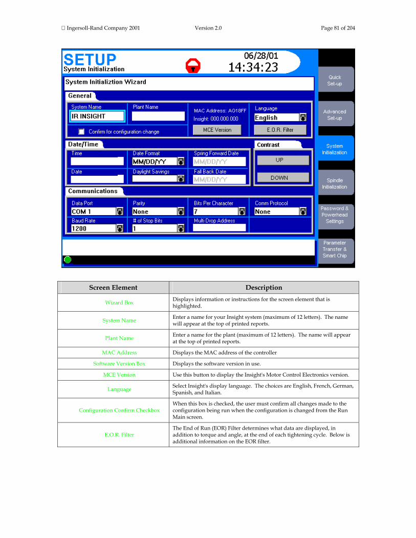
Ingersoll-Rand Company 2001 Version 2.0 Page 81 of 204
Screen Element Description
Wizard Box Displays information or instructions for the screen element that is highlighted.
System Name Enter a name for your Insight system (maximum of 12 letters). The name will appear at the top of printed reports.
Plant Name Enter a name for the plant (maximum of 12 letters). The name will appear at the top of printed reports.
MAC Address Displays the MAC address of the controller
Software Version Box Displays the software version in use.
MCE Version Use this button to display the Insight's Motor Control Electronics version.
Language Select Insight's display language. The choices are English, French, German, Spanish, and Italian.
Configuration Confirm Checkbox When this box is checked, the user must confirm all changes made to the configuration being run when the configuration is changed from the Run Main screen.
E.O.R. Filter The End of Run (EOR) Filter determines what data are displayed, in addition to torque and angle, at the end of each tightening cycle. Below is additional information on the EOR filter.

Ingersoll-Rand Company 2001 Version 2.0 Page 82 of 204
Time Allows the user to reset the correct time. Press the Expand key then enter
the time in 24 hour format.
Date Allows the user to set the correct date. Press the Expand key then enter the date.
Date Format Use this drop box to select MM/DD/YY or DD/MM/YY.
Daylight Savings Use this drop box to enable or disable automatic time adjustment to compensate for daylight savings.
Spring Forward Date If Daylight Savings is enabled, enter the date at which it begins. (The date clocks are set ahead one hour.)
Fall Back Date If Daylight Savings is enabled, enter the date at which it ends. (The date clocks are set back one hour.)
Contrast Up Adjusts screen contrast up.
Contrast Down Adjusts screen contrast down.
Data Port Use this drop box to select the communications port setting. The options are: COM 1, COM 2, COM 3, COM 4, Profibus, or Devicenet.
Baud Rate Use this drop box to set the baud rate at 1200, 2400, 4800, 9600, 19200, or 38400, 57600, or 115,200.
Parity Use this drop box to set parity to None, Odd, or Even.
# of Stop Bits Use this drop box to set the number of stop bits to 1 or 2.
Bits Per Character Use this drop box to set the bits per character to 7 or 8.
Multi Drop Address Enter the address number for the network port's host Data Out protocol. The allowable range is 00 to 99.
Comm Protocol
Select the communications protocol that will be assigned to the communications port selected in the Data Port drop box. The options are None, Host Data Out, E.O.R. Data Out, PFCS, and Bar Code. See additional explanation of these options below.
Settings Button
This button may or may not be present, and the button's name may change, depending on certain settings. It is present when Bar Code, Profibus, or Devicenet have been selected in the Data Port or Comm Protocol drop boxes. If the button is present, clicking it brings up another screen as discussed below.
Message Box The Message Box summarizes system status and provides warnings and alarms.
Insight Controller Software Status Box
This bar shows the status of the Insight Controller Software (ICS), the optional software that allows the Insight to communicate over a network. If the light in the box is green, the ICS is connected and operational. Depending on the ICS's communication status, the box may display additional information
EOR Filter The End of Run (EOR) filter determines the data displayed, in addition to torque and angle, at the end of each tightening cycle. Clicking on the E.O.R Filter button on the System Initialization screen brings up a screen listing the following parameters. To select a parameter from the list, put a check mark in the adjacent check box. To do this, navigate to the box and press the Enter key. As noted in

Ingersoll-Rand Company 2001 Version 2.0 Page 83 of 204
the table below, some of the parameters are checked to display by default. For these parameters, navigating to the box and pressing Enter will uncheck the box.
Parameter Explanation
Shutdown Code A code created after every cycle; for details click here. By default, this parameter is displayed.
Peak Current The maximum current draw during the fastening cycle. By default, this parameter is displayed.
Cycle Time The elapsed time for the fastening cycle. By default, this parameter is displayed.
Peak Slope Peak slope of the torque vs. angle curve
Final Slope Final slope of the torque vs. angle curve
Prevailing Torque Slope The slope of the tightening curve for a prevailing torque strategy
Peak Cut-in Torque The peak cut-in torque for the prevailing torque and drag torque strategies
Peak Prevailing Torque The maximum torque measured during the prevailing torque phase of a prevailing torque strategy
Average Prevailing Torque The average torque measured during the prevailing torque phase of a prevailing torque strategy
Angle at Seat The degrees of angle rotated when seating torque is reached
Torque at Seat The measured torque value when seating torque is reached
Peak Drag torque The maximum torque measured during the drag torque phase of a drag torque strategy
Average Drag Torque The average torque measured during the drag torque phase of a drag torque strategy
Minimum Drag Torque The minimum torque measured during the drag torque phase of a drag torque strategy
Communication Protocol Setup There are four options in the Comm Protocol drop box.
1. None
2. Host Data Out is a handshaking protocol. The host sends a request for data, Insight sends the data, and the host sends a response that the data were received. Click here to see the data output structure.
3. E.O.R. Data Out sends one line of data after every cycle, without a host request. Click here to see the data output structure.
4. Bar Code. Select this option if you have a bar code scanner connected to the COM Port. When you select this option a button labeled Bar Code Settings appears on the lower right corner of the screen.

Ingersoll-Rand Company 2001 Version 2.0 Page 84 of 204
If the data port is set to Bar Code, clicking on the Bar Code Settings button brings up the screen below. Click on the screen elements that have red highlights to learn their function.

Ingersoll-Rand Company 2001 Version 2.0 Page 85 of 204
Screen Element Description Spindle The spindle number to which the bar code data are attached.
Configuration The configuration to which the Criteria (see below) are attached.
Length Enter the size of the bar code. Range is 1-40 characters with a default value of 20.
Use Data From Defines where in the bar code string the software looks for the starting point of the configuration selection criteria. Range is 1-39, and must be less than the value in the Use Data To box.
Use Data To Defines where in the bar code string the software looks for the end position of the configuration selection criteria. Range is 1-39, and must be greater than the value in the Use Data From box.
Criteria The user can enter a bar code value to assign to the configuration. The number of characters must be the same as the range defined in the Use Data From and Use Data to boxes.
Assign When pressed, this button assigns the displayed spindle and configuration to the criteria entered on the screen.
De-Assign When pressed, this button de-links the displayed spindle and configuration from the criteria.
De-Assign All When pressed, all configuration and criteria linked together for the displayed spindle will be de-linked.
Disable Tool Until Scan Check When checked, the Insight will disable the tool until it receives the bar code scan.
OK Use this button to save all changes and return to the System Initialization screen.
Cancel Use this button to cancel all changes and return to the System Initialization screen.
If the data port is set to Profibus, clicking on the Profibus Settings button brings up the screen below. Click on the screen elements that have red highlights to learn their function.
Screen Element Description
Wizard Box Displays information or instructions for the screen element that is highlighted.
Profibus Operation Use this drop box to enable or disable Profibus.
Profibus Address Enter the Profibus address. Range is 2-126, with a default value of 100.
Tool Control Use this drop box to enable or disable tool control.
EOR Data Use this drop box to enable or disable EOR data collection.
OK Use this button to save all changes and return to the System Initialization screen.
Cancel Use this button to cancel all changes and return to the System Initialization screen.

Ingersoll-Rand Company 2001 Version 2.0 Page 86 of 204
If the data port is set to Devicenet, clicking on the Devicenet Settings button brings up the screen below. Click on the screen elements that have red highlights to learn their function.
Screen Element Description
Wizard Box Displays information or instructions for the screen element that is highlighted.
Devicenet Operation Use this drop box to enable or disable Devicenet.
Devicenet Address Enter the Devicenet address. Range is 1-63, with a default value of 30.
Baud Rate Use thus drop box to select the baud rate. Selections are 125 kb/sec, 250 kb/sec, and 500 kb/sec. The default is 500 kb/sec.
Tool Control Use this drop box to enable or disable tool control.
EOR Data Use this drop box to enable or disable EOR data collection.
OK Use this button to save all changes and return to the System Initialization screen.
Cancel Use this button to cancel all changes and return to the System Initialization screen.
This is the end of the Set-up menu System Initialization Screen section. Scroll down to continue your tour or click on another topic at the left. Spindle Initialization Screen You will use this screen to identify which Ingersoll-Rand spindles (tools) are attached to the Insight controller, and to set certain basic spindle operating parameters, such as torque units, start mode, and so on. This screen also has an Auto Calibration button for calibrating the spindles against an external transducer, a Custom Tool button to add a custom tool to the controller's tool list, and a Link Tool button to assign a tool to a particular configuration. Below is the Spindle Initialization screen. Click on the screen elements that have red highlights to learn their function.

Ingersoll-Rand Company 2001 Version 2.0 Page 87 of 204

Ingersoll-Rand Company 2001 Version 2.0 Page 88 of 204
Screen Element Description
Wizard Box Displays information or instructions for the screen element that is highlighted.
Select Spindle Use this drop box to select either Spindle 1, Spindle 2. This drop box will not be present if your Insight is a one-spindle model.
Tool Name
Use this drop box to select the model number of the I-R tool attached to the selected spindle. If your tool’s model number is not listed, see additional instructions below. This box is not selectable (it is grayed out) for Smart Chip tools or if Link Tool is active.
Tube Nut If you want the Insight controller to operate a tube nut tightening tool, set this drop box to Enable.
Auto Calibration Pressing this button allows you to calibrate your tool(s) using an external torque transducer, as described below.
TR Value Use this data entry box to enter the tool’s actual Transducer Range value. The value (labeled TR) is on the tool’s calibration label. Entering the correct value aids calibration.
Angle Constant Use this data entry box to enter the tool’s actual Angle Constant value. The value is on the tool’s calibration label.
Custom Tool This button brings up a screen that allows you to set-up and program a tool not listed in the Tool Type drop box, as described below.
Torque Units Use this drop box to select torque units. The options are Nm, Ft-lb, In-lb, Kg-m, or Kg-cm.
Config. Select
Use this drop box to select the method of switching from one configuration to another. The options are Internal, External Binary, and External Discrete. Internal is selected from the Run Main screen. Discrete indicates an external signal (such as from a switch, socket tray, or PLC). Binary indicates an external coded binary signal.
Spindle Status To operate the tool attached to the spindle, select Enabled. Selecting Disabled prevents tool operation.
Spindle Operation Use this drop box to identify if the start signal is coming from a hand-operated throttle (Hand Tool) or from an I/O signal (Machine Mounted).
Rem. Tool En./Dis. This allows the tool to be remotely enabled and disabled through the I/O connector. Options are On and Off.
Start Mode
Use this drop box to select the type of signal indicating tool start. The options are throttle, pulse, or dual. For hand-held tools, select throttle. Pulse indicates a momentary external signal. Dual requires two switch closures (because some tools require the operator to activate two switches simultaneously to ensure his hands are safely away from the machinery).
Message Box The Message Box summarizes system status and provides warnings and alarms.
Insight Controller Software Status Box
This bar shows the status of the Insight Controller Software (ICS), the optional software that allows the Insight to communicate over a network. If the light in the box is green, the ICS is connected and operational. Depending on the ICS's communication status, the box may display additional information
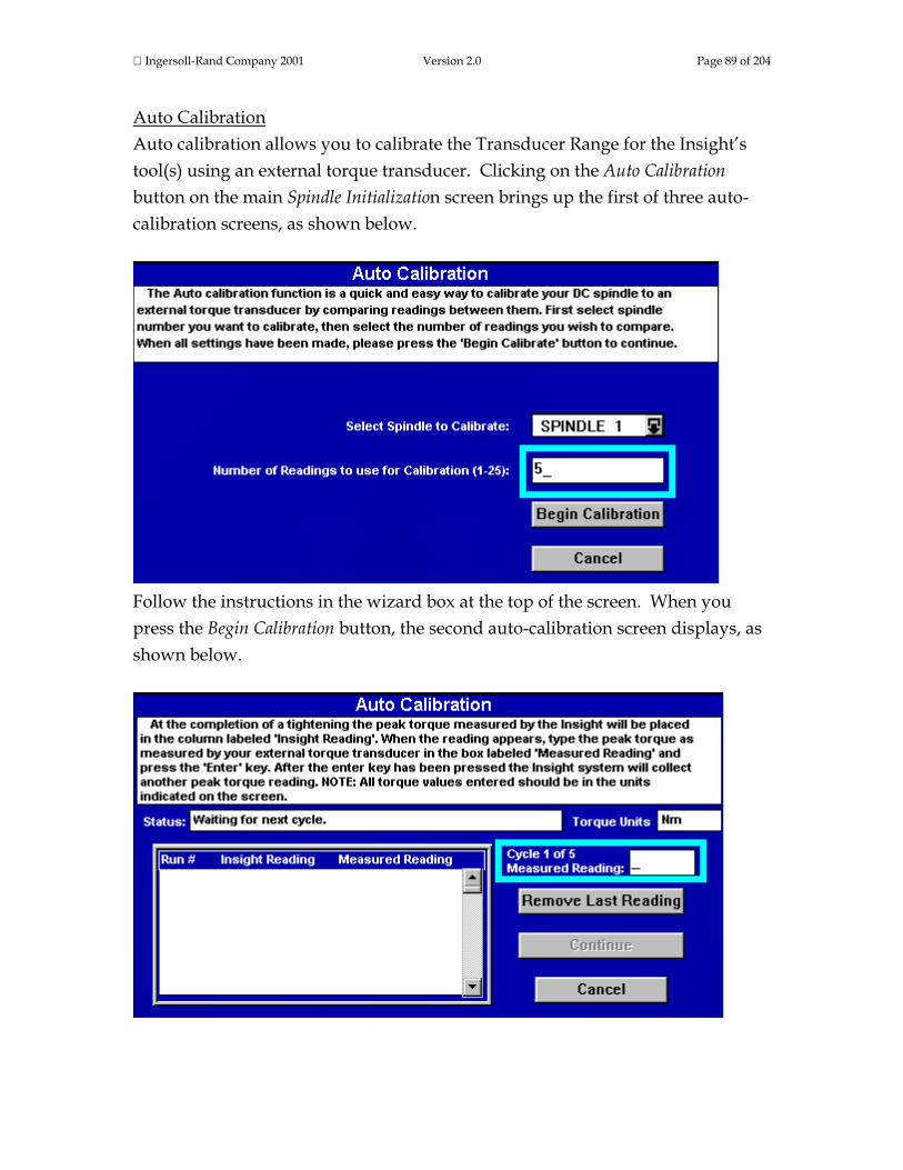
Ingersoll-Rand Company 2001 Version 2.0 Page 89 of 204
Auto Calibration Auto calibration allows you to calibrate the Transducer Range for the Insight’s tool(s) using an external torque transducer. Clicking on the Auto Calibration button on the main Spindle Initialization screen brings up the first of three auto-calibration screens, as shown below.
Follow the instructions in the wizard box at the top of the screen. When you press the Begin Calibration button, the second auto-calibration screen displays, as shown below.

Ingersoll-Rand Company 2001 Version 2.0 Page 90 of 204
Follow the instructions in the wizard box to capture each calibration reading. The Status box will remind you where you are in the calibration cycle. Use the Insight’s numeric keypad to enter the calibration readings in the Cycle # Measured Reading box. When you have entered readings for the correct number of cycles, the Continue button will become active. Pressing the Continue button will bring up the final auto-calibration screen, as shown below.
This third screen displays the calibration results. You can either accept or reject the new calibration factor. If you reject it, the existing Transducer Range value is retained. After making the selection you are asked if you wish to print an Auto Calibration report. Finally, you will be returned to the main Spindle Initialization screen. Custom Tool This button allows you to set-up and calibrate a tool not listed in the Tool Type drop box. Clicking on the Custom Tool button on the main Spindle Initialization screen brings up the screen shown below. Click on the screen elements that have red highlights to learn their function.

Ingersoll-Rand Company 2001 Version 2.0 Page 91 of 204
Screen Element Description
Wizard Box Displays information or instructions for the screen element that is highlighted.
Custom Tool Select either Custom 1 or Custom 2.
Tool Name Use this data entry box to assign a tool name.
Motor Type Select the motor type by selecting the series number of the I-R tool you are using. The options are 120 series, 40 series, and 30 Series.
Transducer Range Use this data entry box to enter the tool’s Transducer Range value. The value (labeled TR) is on the tool’s calibration label. Entering the correct value aids calibration.
Angle Constant Use this data entry box to enter the tool’s Angle Constant value. The value is on the tool’s calibration label.
OK Use this button to save all changes and return to the Spindle Initialization screen.
Cancel Use this button to cancel all changes and return to the Spindle Initialization screen.
This is the end of the Set-up menu Spindle Initialization Screen section. Scroll down to continue your tour or click on another topic at the left.

Ingersoll-Rand Company 2001 Version 2.0 Page 92 of 204
Password and Powerhead Settings Screen This screen is used to set the Insight’s four levels of user passwords, and to set-up certain powerhead functions. Below is the Password and Powerhead Settings screen. Click on the screen elements that have red highlights to learn their function. Scroll down for additional information on the password and powerhead functions.
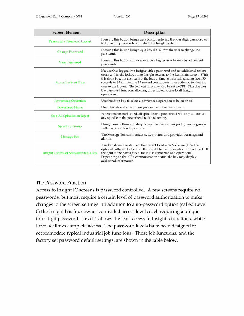
Ingersoll-Rand Company 2001 Version 2.0 Page 93 of 204
Screen Element Description
Password / Password Logout Pressing this button brings up a box for entering the four digit password or to log out of passwords and relock the Insight system.
Change Password Pressing this button brings up a box that allows the user to change the password.
View Password Pressing this button allows a level 3 or higher user to see a list of current passwords.
Access Lockout Time
If a user has logged into Insight with a password and no additional actions occur within the lockout time, Insight returns to the Run Main screen. With this drop box, the user can set the logout time to intervals ranging from 30 seconds to 60 minutes. A 10-second countdown timer activates to alert the user to the logout. The lockout time may also be set to OFF. This disables the password function, allowing unrestricted access to all Insight operations.
Powerhead Operation Use this drop box to select a powerhead operation to be on or off.
Powerhead Name Use this data entry box to assign a name to the powerhead
Stop All Spindles on Reject When this box is checked, all spindles in a powerhead will stop as soon as any spindle in the powerhead fails a fastening.
Spindle / Group Using these buttons and drop boxes, the user can assign tightening groups within a powerhead operation.
Message Box The Message Box summarizes system status and provides warnings and alarms.
Insight Controller Software Status Box
This bar shows the status of the Insight Controller Software (ICS), the optional software that allows the Insight to communicate over a network. If the light in the box is green, the ICS is connected and operational. Depending on the ICS's communication status, the box may display additional information
The Password Function Access to Insight IC screens is password controlled. A few screens require no passwords, but most require a certain level of password authorization to make changes to the screen settings. In addition to a no-password option (called Level 0) the Insight has four owner-controlled access levels each requiring a unique four-digit password. Level 1 allows the least access to Insight’s functions, while Level 4 allows complete access. The password levels have been designed to accommodate typical industrial job functions. Those job functions, and the factory set password default settings, are shown in the table below.

Ingersoll-Rand Company 2001 Version 2.0 Page 94 of 204
Password Level Typical Job Functions Factory Set Default Password
Level 0 No password protection None
Level 1 Operator, Electrical or Mechanical Maintenance 1111
Level 2 Insight IC Programmer 2222
Level 3 Quality Control Engineer 3333
Level 4 Factory or Line Supervisor 4444
If you do not wish to use any passwords (that is, allow all users access to every screen), you must sign in at Level 4 and the set the Access Lockout Time drop box to OFF. If a user attempts to access or change a screen to which he or she is not authorized, a dialogue box will appear requesting the necessary password level. To change a password, the user must sign in on that particular level. The table below shows the password level required to access the Insight IC Menu and Sub Menu screens.
Menu Sub Menu Password Level Required
Run Main 0
Tightening Curves 0
Stats Summary 0
Cycle Log 2, 3, 4
View Parameters 0
Statistics Summary 2, 3, 4
Export 2, 3, 4
Tightening Curves 2, 3, 4
Cycle Log 0
Stats Alarm 2, 3, 4
Set-up Quick Set-up 2, 4
Advanced Set-up 2, 4
System Initialization 2, 4
Spindle Initialization 2, 4
Password and Powerhead All passwords can change their value

Ingersoll-Rand Company 2001 Version 2.0 Page 95 of 204
Settings
Parameter Transfer and Smart Chip 2, 4
Diagnostics System test 1, 2, 4
Discrete Inputs 1, 2, 4
Discrete Outputs 1, 4
Event Log 1, 2, 4
Tool Test 1, 4
Print All Screens 0
Help All Screens 0
The Powerhead Function The powerhead function offers the user powerful control over tightening operations. The first step in understanding this function is to understand the function's terminology. A Powerhead is two or more spindles that all start with a common start signal and have a common configuration. A Group is one or more spindles in a powerhead that have an identical number of fastening steps. A Step is one fastening operation (strategy), such as torque control, angle control, etc. A Configuration is a step or sequence of steps that define a distinct tightening operation. For the Insight IC each spindle or powerhead can have up to 32 configurations. A sync (synchronization) point is a parameter that can be set to require all spindles in a group to complete the step before starting the next step. To perform various powerhead operations, follow the steps below.
Assigning a Powerhead 1. Select On from the Powerhead Operation drop box. 2. If desired, enter a name in the Powerhead Name data entry box. 3. Select the group number for each spindle.
To edit a powerhead follow the above steps, changing the group numbers as desired.

Ingersoll-Rand Company 2001 Version 2.0 Page 96 of 204
Deleting a Powerhead 1. Select Off from the Powerhead Operation drop box. 2. When the warning box appears, select Yes
This is the end of the Set-up menu Password and Powerhead Settings Screen section. Scroll down to continue your tour or click on another topic at the left. Parameter Transfer and Smart Chip Screen The parameter transfer function is used to download or save Insight IC parameters or new versions of the Insight software from or to removable media Some Ingersoll-Rand tools are equipped with a Smart Chip. These chips store parameters that are specific to each tool and read or displayed on the Insight IC. This capability will be in a future release of the Insight IC. Below is the Parameter Transfer and Smart Chip screen. Click on the screen elements that have red highlights to learn their function.

Ingersoll-Rand Company 2001 Version 2.0 Page 97 of 204
Screen Element Description
Load Data To load parameter data set click on this button after first checking the adjacent box to specify whether the upload is from a disk inserted in the floppy disk drive or a flash disk inserted in the PCMCIA slot.
Save Data
To save parameter data set click on this button after first checking the adjacent box to specify whether the data is to be stored on a floppy disk inserted in the disk drive or a flash disk. inserted in the PCMCIA slot. You will be prompted to name the saved file.
Store … to Flash Disk Checking this box saves the Master Plots and Cycle Log data to a flash disk inserted in the PCMCIA slot.
Load Software To upload new software click on this button after first checking the adjacent box to specify whether the upload is graphics software or Motor Controller software.
Message Box The Message Box summarizes system status and provides warnings and alarms.
Insight Controller Software Status Box
This bar shows the status of the Insight Controller Software (ICS), the optional software that allows the Insight to communicate over a network. If the light in the box is green, the ICS is connected and operational. Depending on the ICS's communication status, the box may display additional information
This is the end of the Set-up menu Parameter Transfer and Smart Chip Screen section and the end of The Set-up Menus topic. To go to the next section of this manual click on the arrow below, or click on another topic at the left. The Diagnostics Menus The Diagnostics menu allows the user to check the overall system health of the Insight IC Fastening System with Graphics Display. This function also diagnoses system problems. The user can view diagnostic test results and store them for future reference. The Diagnostics menu has five sub-menu screens. Click on the links below to go to the discussion of those screens, or continue your tour and these topics will be introduced in the sequence shown. The thumbnails above each menu screen link will help you recognize their look and screen layout.
System Test Screen Discrete Input Screen Discrete Outputs Screen Event Log Screen Tools Test Screen

Ingersoll-Rand Company 2001 Version 2.0 Page 98 of 204
System Test Screen With this screen the user can request and display diagnostics test results on the tightening tools (spindles) and on the Motor Controllers (MCs). Below is a typical System Test screen graphic. Click on the screen elements that have red highlights to learn their function.

Ingersoll-Rand Company 2001 Version 2.0 Page 99 of 204
Screen Element Description
Wizard Box Displays information or instructions for the screen element that is highlighted.
Select Spindle Use this drop box to select either Spindle 1 or Spindle 2 for testing. This drop box will not be present if your Insight is a one-spindle model.
Start Test This button initiates the system diagnostics test. The test results are then displayed on the left-hand side of the screen’s main window.
Save Results This button stores the system diagnostics test results and displays them on the right-hand side of the screen’s main window.
Main Window
When the user performs a systems test, the results are displayed as a table on the left-hand side of this window (the side labeled NEW). If there are test results already displayed there, they are overwritten. If the Save Results button is pressed, the test results displayed on the left-hand side of the window are moved to the right-hand side and stored, overwriting any stored test results previously displayed there. Below is additional information on the specific test results displayed in this window.
Message Box The Message Box summarizes system status and provides warnings and alarms.
Insight Controller Software Status Box
This bar shows the status of the Insight Controller Software (ICS), the optional software that allows the Insight to communicate over a network. If the light in the box is green, the ICS is connected and operational. Depending on the ICS's communication status, the box may display additional information
The following system test data are displayed in the main window. When the Insight IC displays these data, it will show the value measured during the test and also whether that value is within allowable parameters (PASS) or not (FAIL).
Test Data Element Explanation
TOOL
Motor temperature Checks motor temperature
Motor test Motor's Kt value (Peak Torque/Peak Motor Torque)
Amplifier offset MC's offset voltage (as % of Shunt Cal voltage)
Bridge offset Torque transducer's offset voltage (as % of Shunt Cal voltage)
Shunt calibration Front-end electronics gain (as % of ideal Shunt Cal voltage)
Excitation voltage +ve Transducer's positive excitation voltage
Excitation voltage -ve Transducer's negative excitation voltage
Hall signal test Checks if Hall sensors are operating correctly
MOTOR CONTROLLER
MC temperature Displays MC's internal temperature
A/D reference voltage Measures A/D converter's reference voltage

Ingersoll-Rand Company 2001 Version 2.0 Page 100 of 204
Note that the System Test window is a display box. The user can enter this box simply by navigating to the window with the arrow keys, and using the arrow keys to scroll through the table. As the user scrolls through the System Test parameters, information on each parameter displays in the wizard box. This includes an explanation of the parameter, the expected range (if applicable), and guidance on what to do if the parameter test failed.
This is the end of the Diagnostics menu System Test Screen section. Scroll down to continue your tour, or click on another topic at the left. Discrete Inputs Screen On the left side panel of the Insight controller are Spindle I/O (Input/Output) connectors. (For an illustration of where these connectors are located, click here.) With this screen, the user can determine whether any of the required input signals are present. Below is a typical Discrete Inputs screen graphic. Click on the screen elements that have red highlights to learn their function. See below for additional explanation of this function.

Ingersoll-Rand Company 2001 Version 2.0 Page 101 of 204
Screen Element Description
Select Spindle Use this drop box to select either Spindle 1 or Spindle 2 for testing. This drop box will not be present if your Insight is a one-spindle model.
Main Window
The spindle input signals are listed on the screen. If the input signal is present, the circle to the left of the signal will be filled-in. If no signal is present, the circle will be white. Below is additional information on the input signals displayed in this window.
Message Box The Message Box summarizes system status and provides warnings and alarms.
Insight Controller Software Status Box
This bar shows the status of the Insight Controller Software (ICS), the optional software that allows the Insight to communicate over a network. If the light in the box is green, the ICS is connected and operational. Depending on the ICS's communication status, the box may display additional information
The Insight IC can be delivered in three versions. A one- or two-spindle Base System with 8 input signals per spindle, a one- or two-spindle Expanded System with 24 input signals per spindle, and a one-spindle Ultra Expanded System with 40 input signals. When energized, the circle to the left of the input signal name in the main screen window will be filled in.
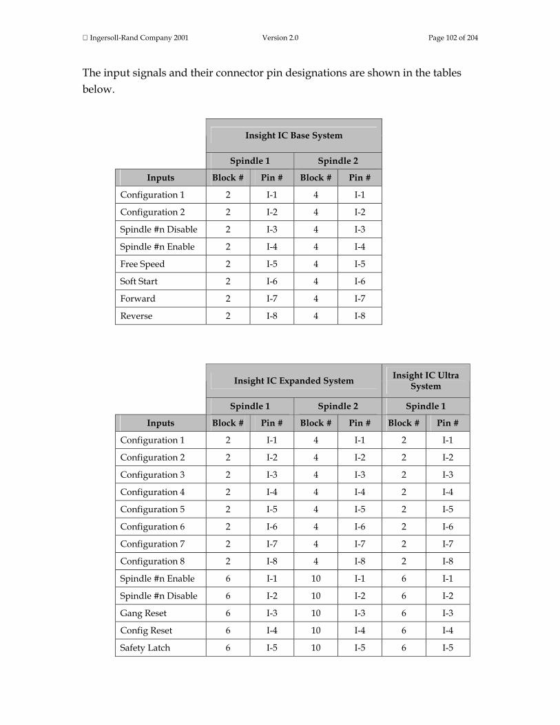
Ingersoll-Rand Company 2001 Version 2.0 Page 102 of 204
The input signals and their connector pin designations are shown in the tables below.
Insight IC Base System
Spindle 1 Spindle 2
Inputs Block # Pin # Block # Pin #
Configuration 1 2 I-1 4 I-1
Configuration 2 2 I-2 4 I-2
Spindle #n Disable 2 I-3 4 I-3
Spindle #n Enable 2 I-4 4 I-4
Free Speed 2 I-5 4 I-5
Soft Start 2 I-6 4 I-6
Forward 2 I-7 4 I-7
Reverse 2 I-8 4 I-8
Insight IC Expanded System Insight IC Ultra
System
Spindle 1 Spindle 2 Spindle 1
Inputs Block # Pin # Block # Pin # Block # Pin #
Configuration 1 2 I-1 4 I-1 2 I-1
Configuration 2 2 I-2 4 I-2 2 I-2
Configuration 3 2 I-3 4 I-3 2 I-3
Configuration 4 2 I-4 4 I-4 2 I-4
Configuration 5 2 I-5 4 I-5 2 I-5
Configuration 6 2 I-6 4 I-6 2 I-6
Configuration 7 2 I-7 4 I-7 2 I-7
Configuration 8 2 I-8 4 I-8 2 I-8
Spindle #n Enable 6 I-1 10 I-1 6 I-1
Spindle #n Disable 6 I-2 10 I-2 6 I-2
Gang Reset 6 I-3 10 I-3 6 I-3
Config Reset 6 I-4 10 I-4 6 I-4
Safety Latch 6 I-5 10 I-5 6 I-5

Ingersoll-Rand Company 2001 Version 2.0 Page 103 of 204
Limit Switch In 6 I-6 10 I-6 6 I-6
Limit Switch Out 6 I-7 10 I-7 6 I-7
Bypass Spindle 6 I-8 10 I-8 6 I-8
Free Speed 8 I-1 12 I-1 8 I-1
Soft Start 8 I-2 12 I-2 8 I-2
Forward 8 I-3 12 I-3 8 I-3
Reverse 8 I-4 12 I-4 8 I-4
Not Available 8 I-5 12 I-5 8 I-5
Not Available 8 I-6 12 I-6 8 I-6
Not Available 8 I-7 12 I-7 8 I-7
Not Available 8 I-8 12 I-8 8 I-8
The Ultra System has additional inputs reserved for future expansion on: Block 10 Pins I-1 thru I-8 AND Block 12 Pins I-9 thru I-16
This is the end of the Diagnostics menu Discrete Inputs Screen section. Scroll down to continue your tour or click on another topic at the left. Discrete Outputs Screen On the left side panel of the Insight controller are Spindle I/O (Input/Output) connectors. (For an illustration of where these connectors are located, click here.) With this screen, the user can artificially activate an output signal. This function is typically used for troubleshooting; for example to send a signal to an external device (such as a PLC) to verify the device is operating correctly. Below is a typical Discrete Outputs screen graphic. Click on the screen elements that have red highlights to learn their function. See below for additional explanation of this function.

Ingersoll-Rand Company 2001 Version 2.0 Page 104 of 204
Screen Element Description
Select Spindle Use this drop box to select either Spindle 1 or Spindle 2 for testing. This drop box will not be present if your Insight is a one-spindle model.
Output Signals Window The spindle output signals are listed on the screen. If the check box to the left of the output signal is checked, that output signal will be sent. Below is additional information on the input signals displayed in this window.
Output Function Additional output signals can be selected using these drop boxes.
Status A series of checkboxes to make output signals active.
Message Box The Message Box summarizes system status and provides warnings and alarms.
Insight Controller Software Status Box
This bar shows the status of the Insight Controller Software (ICS), the optional software that allows the Insight to communicate over a network. If the light in the box is green, the ICS is connected and operational. Depending on the ICS's communication status, the box may display additional information
The Insight IC can be delivered in three versions. A one- or two-spindle Base System with 8 output signals per spindle, a one- or two-spindle Expanded System with 24 output signals per spindle, and a one-spindle Ultra Expanded System with 40 output signals. To manually activate an output, check the checkbox next to the output name.
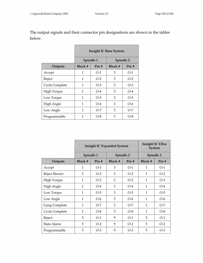
Ingersoll-Rand Company 2001 Version 2.0 Page 105 of 204
The output signals and their connector pin designations are shown in the tables below.
Insight IC Base System
Spindle 1 Spindle 2
Outputs Block # Pin # Block # Pin #
Accept 1 O-1 3 O-1
Reject 1 O-2 3 O-2
Cycle Complete 1 O-3 3 O-3
High Torque 1 O-4 3 O-4
Low Torque 1 O-5 3 O-5
High Angle 1 O-6 3 O-6
Low Angle 1 O-7 3 O-7
Programmable 1 O-8 3 O-8
Insight IC Expanded System Insight IC Ultra
System
Spindle 1 Spindle 2 Spindle 1
Outputs Block # Pin # Block # Pin # Block # Pin #
Accept 1 O-1 3 O-1 1 O-1
Reject Buzzer 1 O-2 3 O-2 1 O-2
High Torque 1 O-3 3 O-3 1 O-3
High Angle 1 O-4 3 O-4 1 O-4
Low Torque 1 O-5 3 O-5 1 O-5
Low Angle 1 O-6 3 O-6 1 O-6
Gang Complete 1 O-7 3 O-7 1 O-7
Cycle Complete 1 O-8 3 O-8 1 O-8
Reject 5 O-1 9 O-1 5 O-1
Stats Alarm 5 O-2 9 O-2 5 O-2
Programmable 5 O-3 9 O-3 5 O-3

Ingersoll-Rand Company 2001 Version 2.0 Page 106 of 204
Programmable 5 O-4 9 O-4 5 O-4
Programmable 5 O-5 9 O-5 5 O-5
Programmable 5 O-6 9 O-6 5 O-6
Programmable 5 O-7 9 O-7 5 O-7
Programmable 5 O-8 9 O-8 5 O-8
Programmable 7 O-1 11 O-1 7 O-1
Programmable 7 O-2 11 O-2 7 O-2
Programmable 7 O-3 11 O-3 7 O-3
Programmable 7 O-4 11 O-4 7 O-4
Programmable 7 O-5 11 O-5 7 O-5
Programmable 7 O-6 11 O-6 7 O-6
Programmable 7 O-7 11 O-7 7 O-7
Programmable 7 O-8 11 O-8 7 O-8
The Ultra System has additional programmable inputs on: Block 9 Pins O-1 thru O-8 AND Block 11 Pins O-1 thru O-8
This is the end of the Diagnostics menu Discrete Outputs Screen section. Scroll down to continue your tour or click on another topic at the left. Event Log Screen The Event Log screen is a large scrollable window that logs the date and time that certain important Insight events occur. The events recorded include hardware and software faults (such as a tool over-temperature event), and significant user actions (such as changes to a tool's transducer range or angle constant). This record of significant events can help users investigate and troubleshoot problems.

Ingersoll-Rand Company 2001 Version 2.0 Page 107 of 204
This is the end of the Diagnostics menu Event Log Screen section. Scroll down to continue your tour or click on another topic at the left. Tool Test Screen This screen allows the user to interrupt regular tightening operations in order to perform several tool tests. This is useful in troubleshooting any problems that appear to originate with an I-R spindle or tool.

Ingersoll-Rand Company 2001 Version 2.0 Page 108 of 204
Screen Element Description Select Spindle Use this drop box to select the spindle to be tested.
Lamp Test
Check one of the radio buttons (circles) to turn the lamp test on or off. If the lamp test is on the Insight cycles through all the lights on the tool so the user can see if they are working properly. A lamp output signal will also be sent if there is an external light box attached to the Insight so the user can also verify that it is working correctly.
Speed This box displays the tool's dynamic speed.
Torque This box displays the dynamic torque, which can indicate the drag torque in the tool's gearbox.
Angle This box displays a continuous readout of the tool's angle count. The display continues until the Angle reset button on the screen is pressed.
Message Box The Message Box summarizes system status and provides warnings and alarms.
Insight Controller Software Status Box
This bar shows the status of the Insight Controller Software (ICS), the optional software that allows the Insight to communicate over a network. If the light in the box is green, the ICS is connected and operational. Depending on the ICS's communication status, the box may display additional information
Ingersoll-Rand Company 2001 Version 2.0 Page 109 of 204
This is the end of the Tool Test Screen section and the end of The Diagnostics Menus topic. To go to the next section of this manual click on the arrow below, or click on another topic at the left.
Print Menus The Insight IC Fastening System with Graphics Display can print a large number of standard reports on fastening data, statistics, system settings and parameters, and many other topics. From within any of the controller’s menus or sub-menus, the user can press the Print Main Menu Key on the Insight front panel, and a print menu displays. The display is context sensitive. That is, Insight recognizes what menu it is in (Run, Statistics, Set-up, or Diagnostics) when the user presses the Print key, and displays the appropriate report printing options. While Insight offers many printed report options, each one is self-explanatory, and it is not necessary to explain each print screen. Simply use the arrow keys and the Enter key to navigate through and select the option you want. Occasionally, you may be asked to mark a checkbox (use the Enter key to check or uncheck the box) or enter a number in a data entry box (use the numeric keypad). To go to the next section of this manual click on the arrow below, or click on another topic at the left.
Help Menus The Insight IC Fastening System with Graphics Display has built-in Help functions that the user can access at any time, simply by pressing the Help Main Menu Key on the front panel. The Help is context sensitive. That is, when the user presses the Help key the Insight recognizes what main menu and sub-menu it is in, and it also recognizes the current (highlighted) screen element, and displays the appropriate information for the highlighted item. Below is a typical Help screen. (It is for the Run Menu, Main screen sub-menu). Click your mouse on screen elements that have red highlights to learn their function.

Ingersoll-Rand Company 2001 Version 2.0 Page 110 of 204
Pressing the Help Main Menu button on the main menu screen brings up the Help screen shown below. Note that Insight's four main functions are listed, and there is a button for every sub-menu under each function. Pressing any of the sub-menu buttons brings up a Help file on that topic.

Ingersoll-Rand Company 2001 Version 2.0 Page 111 of 204
Pressing the Go To Topic button on the first Help screen brings up the Help screen shown below. There is an alphabetical list of Insight topics in the drop box on the left of the screen. Also shown is the principal screen location where each topic is addressed, entered, set, selected, and so on. To display the Help file for a topic, navigate to the drop box with the arrow keys and press the Expand key. Then use the arrow keys to bring that topic to the top of the list, and press Enter.

Ingersoll-Rand Company 2001 Version 2.0 Page 112 of 204
This is the end of the Help Menus topic, and the end of the entire section devoted to Menus and Sub-Menus. To go to the next section of this manual click on the arrow below, or click on another topic at the left. Parameters This section describes every parameter used by the Insight IC Fastening System with Graphics Display. If you are looking for information on a specific parameter, click here to go to the alphabetic list of all the Insight parameters. Otherwise scroll down through this brief section to learn how the section is organized and the kinds of parameter information it provides. Earlier in this document you learned to work with all of the Insight's main menu and sub-menu screens. You learned that for all of these menus and sub-menus there are many individual parameters that can be selected, set, specified, adjusted, and so on. Some of the parameters are unique, only applying to one specific menu screen. Others are common and appear in many different menu screens.

Ingersoll-Rand Company 2001 Version 2.0 Page 113 of 204
If you encounter a parameter with which you are unfamiliar, this section is designed to be a quick way for you to learn everything about that parameter, regardless of where it appears within any of the Insight's menus. To learn how we have presented the parameter information click on the example below, then roll your mouse over each screen element in the graphic.
Angle Lo Limit
Angle Lo Limit The minimum angle (in degrees) through which the fastener must turn. (User-entered)
Where the Parameter is Found and Its Range and Default Values
Main Menu Sub-Menu Location within Sub-Menu Range Default Value
Set-up Quick Set-up Data entry box #8 under Torque Control strategy 0 – 32000 0
Set-up Quick Set-up Data entry box #6 under Angle Control strategy 0 – 32000 Angle Target – 10%
Set-up Advanced Set-up In Parameter List when strategy is Torque Control 0 – 32000 0
Set-up Advanced Set-up In Parameter List when strategy is Angle Control 0 – 32000 Angle Target – 10%
Screen Element Description Angle Lo Limit The parameter’s name.
Box to right of name The parameter’s definition, and whether the parameter is entered by the user or is automatically calculated by the Insight system.
Make the first three columns one roll-over For user-entered parameters, these columns tell you all the locations from which the parameter can be programmed. For system-calculated parameters, these columns tell you where the parameter is displayed.
Make the last two columns one roll-over For each parameter location, these columns give the parameter’s allowable range and default value, if applicable.
Below is a complete alphabetical list of all the parameters used by the Insight IC Fastening System with Graphics Display. Click on any parameter to display its information.
# for Sigma The number of fastenings used to calculate sigma. (System-calculated)

Ingersoll-Rand Company 2001 Version 2.0 Page 114 of 204
Where the Parameter is Found and Its Range and Default Values
Main Menu Sub-Menu Location within Sub-Menu Range Default Value
Run Stats Summary Population and Sample Statistics Tables NA NA
Stats Summary Population and Sample Statistics Tables NA NA
# Hi Rejects The number of fastenings rejected because the target parameter’s final value exceeded the acceptable maximum value. (System-calculated)
Where the Parameter is Found and Its Range and Default Values
Main Menu Sub-Menu Location within Sub-Menu Range Default Value
Run Stats Summary Population Statistics Table NA NA
Stats Summary Population Statistics Table NA NA
# Lo Rejects The number of fastenings rejected because the target parameter’s final value did not reach the acceptable minimum value. (System-calculated)
Where the Parameter is Found and Its Range and Default Values
Main Menu Sub-Menu Location within Sub-Menu Range Default Value
Run Stats Summary Population Statistics Table NA NA
Stats Summary Population Statistics Table NA NA
# of Chords The number of slope calculations that must exceed the Deviation Limit (see parameter) to define the end of the Prevailing Torque Zone. (User-entered)
Where the Parameter is Found and Its Range and Default Values
Main Menu Sub-Menu Location within Sub-Menu Range Default Value
Set-up Advanced Set-up Prevailing Torque Strategy 1 - 10 1
# of Stop Bits The number of stop bits sent in the communications string when Insight communicates with an external RS-232 serial device. (User-entered)
Where the Parameter is Found and Its Range and Default Values
Main Menu Sub-Menu Location within Sub-Menu Range Default Value
Set-up System Initialization Drop box under Communications 1 or 2 1

Ingersoll-Rand Company 2001 Version 2.0 Page 115 of 204
# Rejects % Number and % of fastenings that did not meet the tightening limits. (System-calculated)
Where the Parameter is Found and Its Range and Default Values
Main Menu Sub-Menu Location within Sub-Menu Range Default Value
Run Main Under the Var. 1 and Var. 2 drop boxes NA NA
Run Stats Summary Population Statistics Table NA NA
Stats Summary Population Statistics Table NA NA
# Rejects Hi\Lo The number of fastenings that were rejected because they above \ below the tightening limits. (System-calculated)
Where the Parameter is Found and Its Range and Default Values
Main Menu Sub-Menu Location within Sub-Menu Range Default Value
Run Main Under the Var. 1 and Var. 2 drop boxes NA NA
Run Stats Summary Population Statistics Table NA NA
Stats Summary Population Statistics Table NA NA
# OK The number of fastenings that met the tightening parameters. (System-calculated)
Where the Parameter is Found and Its Range and Default Values
Main Menu Sub-Menu Location within Sub-Menu Range Default Value
Run Main Under the Var. 1 and Var. 2 drop boxes NA NA
Run Stats Summary Population Statistics Table NA NA
Stats Summary Population Statistics Table NA NA
6 Sigma Six times the value of sigma (σ). (System-calculated) (See Sigma in Parameters listing.)
Where the Parameter is Found and Its Range and Default Values
Main Menu Sub-Menu Location within Sub-Menu Range Default Value
Run Main Under the Var. 1 and Var. 2 drop boxes NA NA
Run Stats Summary Under the Population Statistics and Sample Statistics drop boxes
NA NA
Stats Summary Under the Population Statistics and Sample Statistics drop boxes
NA NA

Ingersoll-Rand Company 2001 Version 2.0 Page 116 of 204
A/D Reference Voltage A voltage measurement used to test the analog to digital reference voltage. Insight measures the voltage and assigns either PASS or FAIL. (System-calculated)
Where the Parameter is Found and Its Range and Default Values
Main Menu Sub-Menu Location within Sub-Menu Range Default Value
Diagnostics System Test Within the main window NA NA
Acceleration The rate at which a tool accelerates up to its free speed, where 100% is its maximum acceleration. (User-entered)
Where the Parameter is Found and Its Range and Default Values
Main Menu Sub-Menu Location within Sub-Menu Range Default Value
Set-up Advanced Set-up In Parameter List for the Engage step 30 - 100% 90%
Access Lockout Time If a user has logged into Insight with a password and no additional actions occur within the lockout time, the Insight locks the software. (User-entered)
Where the Parameter is Found and Its Range and Default Values
Main Menu Sub-Menu Location within Sub-Menu Range Default Value
Set-up Password and Powerhead Settings Access Lockout Time drop box
OFF - 60 min. in specific increments
5 minutes
Activate Yield Override When checked activates the yield override function torque control and angle control strategies. . (User-entered)
Where the Parameter is Found and Its Range and Default Values
Main Menu Sub-Menu Location within Sub-Menu Range Default Value
Set-up Advanced Set-up When Torque Control or Angle Control is selected as the strategy
Checked or Unchecked Unchecked
Amplifier Offset The signal offset voltage generated by the Motor Controller’s front end electronics (expressed as % of Shunt Cal voltage). Insight measures the voltage and assigns either PASS or FAIL. (System-calculated)
Where the Parameter is Found and Its Range and Default Values
Main Menu Sub-Menu Location within Sub-Menu Range Default Value
Diagnostics System Test Within the main window NA NA

Ingersoll-Rand Company 2001 Version 2.0 Page 117 of 204
Angle at Seat The degrees of angle rotated when seating torque is reached (applies to a prevailing torque strategy). (System-calculated)
Where the Parameter is Found and Its Range and Default Values
Main Menu Sub-Menu Location within Sub-Menu Range Default Value
Run Main Under the Var. 1 and Var. 2 drop boxes NA NA
Set-up System Initialization Under the EOR (End of Run) Filter button NA NA
Angle Cnt at Drag TQ For a drag torque strategy, the degrees of angle rotated when the drag torque step is complete. (System-calculated)
Where the Parameter is Found and Its Range and Default Values
Main Menu Sub-Menu Location within Sub-Menu Range Default Value
Run Main Under the Var. 1 and Var. 2 drop boxes NA NA
Angle Constant A value used by the Insight to translate motor Hall pulses into spindle degrees of rotation. Enter the Angle Constant value found on the tool’s calibration label in the Angle Constant data entry box. (User-entered)
Where the Parameter is Found and Its Range and Default Values
Main Menu Sub-Menu Location within Sub-Menu Range Default Value
Set-up Spindle Initialization A data entry box within the main window
Depends on tool selected
Depends on tool selected
Angle for Backout The number of degrees the tool will reverse to achieve backout. (User-entered)
Where the Parameter is Found and Its Range and Default Values
Main Menu Sub-Menu Location within Sub-Menu Range Default Value
Set-up Advanced Set-up In Parameter List when strategy is Backout 0 - 32000 0
Angle for Backout Retry Number of degrees the tool will automatically reverse on a tightening fault, before a retry is started. (User-entered)
Where the Parameter is Found and Its Range and Default Values
Main Menu Sub-Menu Location within Sub-Menu Range Default Value
Set-up Advanced Set-up (in Engage step)
In Parameter List when strategy is Fault Backout 0 - 32000 0

Ingersoll-Rand Company 2001 Version 2.0 Page 118 of 204
Angle for Fault Backout Number of degrees the tool will automatically reverse on a tightening fault, when all retries have failed. (User-entered)
Where the Parameter is Found and Its Range and Default Values
Main Menu Sub-Menu Location within Sub-Menu Range Default Value
Set-up Advanced Set-up (in Engage step)
In Parameter List when strategy is Fault Backout 0 - 32000 0
Angle Hi Limit The maximum allowable angle through which the fastener may turn. (User-entered)
Where the Parameter is Found and Its Range and Default Values
Main Menu Sub-Menu Location within Sub-Menu Range Default Value
Set-up Quick Set-up Data entry box #7 under Torque Control strategy 0 - 32000 32000
Set-up Quick Set-up Data entry box #5 under Angle Control strategy 0 - 32000 Angle Target + 10%
Set-up Quick Set-up Data entry box #8 under Yield Control strategy 0 - 32000 32000
Set-up Advanced Set-up In Parameter List when strategy is Torque Control 0 - 32000 32000
Set-up Advanced Set-up In Parameter List when strategy is Angle Control 0 - 32000 Angle Target + 10%
Set-up Advanced Set-up In Parameter List when strategy is Yield Control 0 - 32000 32000
Set-up Advanced Set-up In Parameter List when strategy is Fault Backout 0 - 32000 Backout Angle +
10%
Angle Into Yield The number of degrees the tool rotates beyond the onset of yield to constitute complete tightening. (User-entered)
Where the Parameter is Found and Its Range and Default Values
Main Menu Sub-Menu Location within Sub-Menu Range Default Value
Set-up Quick Set-up Data entry box #5 under Yield Control strategy 0 - 32000 0
Set-up Advanced Set-up
In Parameter List when Torque, Angle, or Yield Control strategy is selected
0 - 32000 0
Angle Into Yield Overshoot
If tightenings are routinely overshooting the Angle Into Yield, the tool will be shut off this many degrees before Angle Into Yield. (User-entered)
Where the Parameter is Found and Its Range and Default Values
Main Menu Sub-Menu Location within Sub-Menu Range Default Value
Set-up Advanced Set-up In Parameter List when strategy is Yield Control
0 – Angle Into Yield
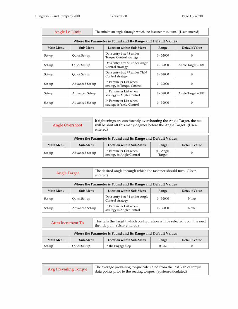
Ingersoll-Rand Company 2001 Version 2.0 Page 119 of 204
Angle Lo Limit The minimum angle through which the fastener must turn. (User-entered)
Where the Parameter is Found and Its Range and Default Values
Main Menu Sub-Menu Location within Sub-Menu Range Default Value
Set-up Quick Set-up Data entry box #8 under Torque Control strategy 0 - 32000 0
Set-up Quick Set-up Data entry box #6 under Angle Control strategy 0 - 32000 Angle Target – 10%
Set-up Quick Set-up Data entry box #9 under Yield Control strategy 0 - 32000 0
Set-up Advanced Set-up In Parameter List when strategy is Torque Control 0 - 32000 0
Set-up Advanced Set-up In Parameter List when strategy is Angle Control 0 - 32000 Angle Target – 10%
Set-up Advanced Set-up In Parameter List when strategy is Yield Control 0 - 32000 0
Angle Overshoot If tightenings are consistently overshooting the Angle Target, the tool will be shut off this many degrees before the Angle Target. (User-entered)
Where the Parameter is Found and Its Range and Default Values
Main Menu Sub-Menu Location within Sub-Menu Range Default Value
Set-up Advanced Set-up In Parameter List when strategy is Angle Control
0 – Angle Target 0
Angle Target The desired angle through which the fastener should turn. (User-entered)
Where the Parameter is Found and Its Range and Default Values
Main Menu Sub-Menu Location within Sub-Menu Range Default Value
Set-up Quick Set-up Data entry box #4 under Angle Control strategy 0 - 32000 None
Set-up Advanced Set-up In Parameter List when strategy is Angle Control 0 - 32000 None
Auto Increment To This tells the Insight which configuration will be selected upon the next throttle pull. (User-entered)
Where the Parameter is Found and Its Range and Default Values
Main Menu Sub-Menu Location within Sub-Menu Range Default Value
Set-up Quick Set-up In the Engage step 0 - 32 0
Avg Prevailing Torque The average prevailing torque calculated from the last 360° of torque data points prior to the seating torque. (System-calculated)

Ingersoll-Rand Company 2001 Version 2.0 Page 120 of 204
Where the Parameter is Found and Its Range and Default Values
Main Menu Sub-Menu Location within Sub-Menu Range Default Value
Set-up System Initialization Behind the E.O.R Filter button
Parameter may be
checked or unchecked
Unchecked
Backout Angle Hi The maximum angle through which the fastener will turn during the backout step. (User-entered)
Where the Parameter is Found and Its Range and Default Values
Main Menu Sub-Menu Location within Sub-Menu Range Default Value
Set-up Advanced Set-up In Parameter List when strategy is Backout 0 - 32000 0
Backout Angle Lo The minimum angle through which the fastener will turn during the backout step. (User-entered)
Where the Parameter is Found and Its Range and Default Values
Main Menu Sub-Menu Location within Sub-Menu Range Default Value
Set-up Advanced Set-up In Parameter List when strategy is Backout 0 - 32000 0
Backout Hi Torque Limit The maximum permissible torque value for the backout phase. (User-entered)
Where the Parameter is Found and Its Range and Default Values
Main Menu Sub-Menu Location within Sub-Menu Range Default Value
Set-up Advanced Set-up In Parameter List when strategy is Backout
Depends on tool selected Maximum of tool
Backout Speed The tool's speed during the backout phase. One of the parameters listed in the Engage step. (User-entered)
Where the Parameter is Found and Its Range and Default Values
Main Menu Sub-Menu Location within Sub-Menu Range Default Value
Set-up Advanced Set-up In Parameter List for every fastening strategy
20-100% of the tool’s full free
speed
90% of the tool’s full free speed
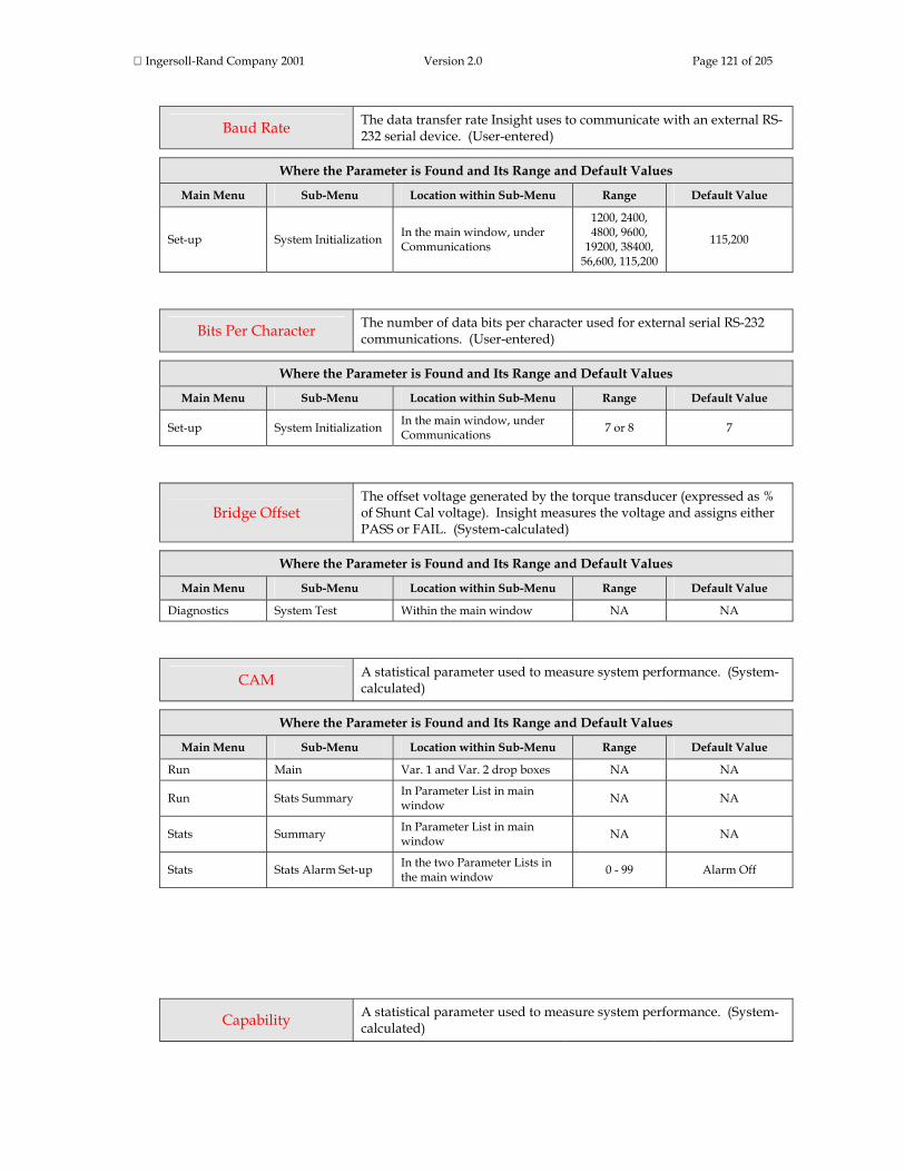
Ingersoll-Rand Company 2001 Version 2.0 Page 121 of 205
Baud Rate The data transfer rate Insight uses to communicate with an external RS-232 serial device. (User-entered)
Where the Parameter is Found and Its Range and Default Values
Main Menu Sub-Menu Location within Sub-Menu Range Default Value
Set-up System Initialization In the main window, under Communications
1200, 2400, 4800, 9600,
19200, 38400, 56,600, 115,200
115,200
Bits Per Character The number of data bits per character used for external serial RS-232 communications. (User-entered)
Where the Parameter is Found and Its Range and Default Values
Main Menu Sub-Menu Location within Sub-Menu Range Default Value
Set-up System Initialization In the main window, under Communications 7 or 8 7
Bridge Offset The offset voltage generated by the torque transducer (expressed as % of Shunt Cal voltage). Insight measures the voltage and assigns either PASS or FAIL. (System-calculated)
Where the Parameter is Found and Its Range and Default Values
Main Menu Sub-Menu Location within Sub-Menu Range Default Value
Diagnostics System Test Within the main window NA NA
CAM A statistical parameter used to measure system performance. (System-calculated)
Where the Parameter is Found and Its Range and Default Values
Main Menu Sub-Menu Location within Sub-Menu Range Default Value
Run Main Var. 1 and Var. 2 drop boxes NA NA
Run Stats Summary In Parameter List in main window NA NA
Stats Summary In Parameter List in main window NA NA
Stats Stats Alarm Set-up In the two Parameter Lists in the main window 0 - 99 Alarm Off
Capability A statistical parameter used to measure system performance. (System-calculated)

Ingersoll-Rand Company 2001 Version 2.0 Page 122 of 205
Where the Parameter is Found and Its Range and Default Values
Main Menu Sub-Menu Location within Sub-Menu Range Default Value
Run Main Var. 1 and Var. 2 drop boxes NA NA
Run Stats Summary In Parameter List in main window NA NA
Stats Summary In Parameter List in main window NA NA
Stats Stats Alarm Set-up In the two Parameter Lists in the main window 0 - 99 Off
Change Password Pressing this button brings up a box with the levels and the current passwords. The level 4 user can then change the passwords by entering a new value and then reentering it to confirm the change. (User-entered)
Where the Parameter is Found and Its Range and Default Values
Main Menu Sub-Menu Location within Sub-Menu Range Default Value
Set-up Password and Powerhead Settings
This button is only available if the Insight is unlocked at any password level
NA NA
Chord Length The number of degrees over which the slope is calculated. (User-entered)
Where the Parameter is Found and Its Range and Default Values
Main Menu Sub-Menu Location within Sub-Menu Range Default Value
Set-up Advanced Set-up Prevailing Torque Strategy 0 - 100 8
Config # Config
Insight can be programmed with up to 32 separate fastening operations, called configurations. Each has a unique Configuration Number from 01 through 32, and may also have a name assigned. (User-entered)
Where the Parameter is Found and Its Range and Default Values
Main Menu Sub-Menu Location within Sub-Menu Range Default Value
Run Main Select Configuration to be Run 01 - 32 Last selected configuration
All other screens All other screens Select Configuration to view 01 - 32 Configuration
selected on Run Main screen
Config Name A suitable alphanumeric name can be assigned to any of Insight’s 32 available configurations. Note: User must press the Expand key to change this parameter. (User-entered)

Ingersoll-Rand Company 2001 Version 2.0 Page 123 of 205
Where the Parameter is Found and Its Range and Default Values
Main Menu Sub-Menu Location within Sub-Menu Range Default Value
Set-up Advanced Set-up Config Name data entry box
Any alphanumeric
name (12 characters
max.)
None
Config. Select Use this drop box to select whether the configuration is selected internally (through the Run Main screen) or externally through the Insight’s I/O connector. (User-entered)
Where the Parameter is Found and Its Range and Default Values
Main Menu Sub-Menu Location within Sub-Menu Range Default Value
Set-up Spindle Initialization Config. Select drop box
Internal,
External Binary, or
External Discrete
Internal
Configuration Confirm When this box is checked, the user must confirm all changes made to the configuration being run when the configuration is changed from the Run Main screen. (User-entered)
Where the Parameter is Found and Its Range and Default Values
Main Menu Sub-Menu Location within Sub-Menu Range Default Value
Set-up System Initialization
A checkbox in the General parameters window labeled "Confirm for configuration change"
Checked or Unchecked Unchecked
Cp A statistical parameter used to measure system capability. (System-calculated)
Where the Parameter is Found and Its Range and Default Values
Main Menu Sub-Menu Location within Sub-Menu Range Default Value
Run Main Var. 1 and Var. 2 drop boxes NA NA
Run Stats Summary In Parameter List in main window NA NA
Stats Summary In Parameter List in main window NA NA
Stats Stats Alarm Set-up In the two Parameter Lists in the main window 0 – 9.9 Alarm Off
CpK A statistical parameter used to measure system capability. (System-calculated)
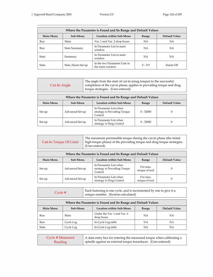
Ingersoll-Rand Company 2001 Version 2.0 Page 124 of 205
Where the Parameter is Found and Its Range and Default Values
Main Menu Sub-Menu Location within Sub-Menu Range Default Value
Run Main Var. 1 and Var. 2 drop boxes NA NA
Run Stats Summary In Parameter List in main window NA NA
Stats Summary In Parameter List in main window NA NA
Stats Stats Alarm Set-up In the two Parameter Lists in the main window 0 – 9.9 Alarm Off
Cut-In Angle The angle from the start of cut-in (snug torque) to the successful completion of the cut-in phase; applies to prevailing torque and drag torque strategies. (User-entered)
Where the Parameter is Found and Its Range and Default Values
Main Menu Sub-Menu Location within Sub-Menu Range Default Value
Set-up Advanced Set-up In Parameter List when strategy is Prevailing Torque Control
0 - 32000 0
Set-up Advanced Set-up In Parameter List when strategy is Drag Control 0 - 32000 0
Cut-In Torque HI Limit The maximum permissible torque during the cut-in phase (the initial high-torque phase) of the prevailing torque and drag torque strategies. (User-entered)
Where the Parameter is Found and Its Range and Default Values
Main Menu Sub-Menu Location within Sub-Menu Range Default Value
Set-up Advanced Set-up In Parameter List when strategy is Prevailing Torque Control
0 to max. torque of tool 0
Set-up Advanced Set-up In Parameter List when strategy is Drag Control
0 to max. torque of tool 0
Cycle # Each fastening is one cycle, and is incremented by one to give it a unique number. (System-calculated)
Where the Parameter is Found and Its Range and Default Values
Main Menu Sub-Menu Location within Sub-Menu Range Default Value
Run Main Under the Var. 1 and Var. 2 drop boxes NA NA
Run Cycle Log In Cycle Log table NA NA
Stats Cycle Log In Cycle Log table NA NA
Cycle # Measured
Reading A data entry box for entering the measured torque when calibrating a spindle against an external torque transducer. (User-entered)
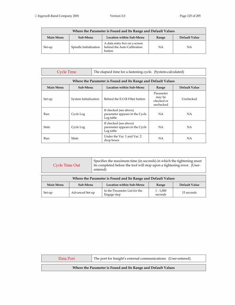
Ingersoll-Rand Company 2001 Version 2.0 Page 125 of 205
Where the Parameter is Found and Its Range and Default Values
Main Menu Sub-Menu Location within Sub-Menu Range Default Value
Set-up Spindle Initialization A data entry box on a screen behind the Auto Calibration button
NA NA
Cycle Time The elapsed time for a fastening cycle. (System-calculated)
Where the Parameter is Found and Its Range and Default Values
Main Menu Sub-Menu Location within Sub-Menu Range Default Value
Set-up System Initialization Behind the E.O.R Filter button
Parameter may be
checked or unchecked
Unchecked
Run Cycle Log If checked (see above) parameter appears in the Cycle Log table
NA NA
Stats Cycle Log If checked (see above) parameter appears in the Cycle Log table
NA NA
Run Main Under the Var. 1 and Var. 2 drop boxes NA NA
Cycle Time Out Specifies the maximum time (in seconds) in which the tightening must be completed before the tool will stop upon a tightening error. (User-entered)
Where the Parameter is Found and Its Range and Default Values
Main Menu Sub-Menu Location within Sub-Menu Range Default Value
Set-up Advanced Set-up In the Parameter List for the Engage step
1 - 1,000 seconds 15 seconds
Data Port The port for Insight’s external communications. (User-entered)
Where the Parameter is Found and Its Range and Default Values

Ingersoll-Rand Company 2001 Version 2.0 Page 126 of 205
Main Menu Sub-Menu Location within Sub-Menu Range Default Value
Set-up System Initialization Drop box in the Communications window
COM1, COM2, COM3, COM4,
Profibus (optional) Devicenet (optional)
COM1
Stats Export Drop box
COM1, COM2, COM3, COM4,
Floppy disk, Flash disk
COM1
Data to Transmit Defines what fastening data will be exported when the communications protocol is set to P.F.C.S. (Plant Floor Communications System). (User-entered)
Where the Parameter is Found and Its Range and Default Values
Main Menu Sub-Menu Location within Sub-Menu Range Default Value
Set-up System Initialization Under the P.F.C.S. Settings button when the Data Port drop box is set to P.F.C.S.
OK Only or
All Cycles OK Only
Date Data entry box to enter today’s date. Note: User must press the Expand key to change this parameter. (User-entered)
Where the Parameter is Found and Its Range and Default Values
Main Menu Sub-Menu Location within Sub-Menu Range Default Value
Set-up System Initialization Data entry box in the Date/Time window NA NA
Date Format Data entry box to select the date format. (User-entered)
Where the Parameter is Found and Its Range and Default Values
Main Menu Sub-Menu Location within Sub-Menu Range Default Value
Set-up System Initialization Data entry box in the Date/Time window
MM/DD/YY or
DD/MM/YY MM/DD/YY
Daylight Savings Drop box to allow the Insight to automatically adjust the time for the start and end of daylight savings. (User-entered)
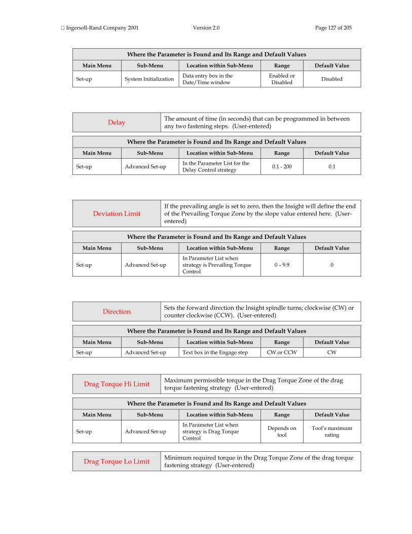
Ingersoll-Rand Company 2001 Version 2.0 Page 127 of 205
Where the Parameter is Found and Its Range and Default Values
Main Menu Sub-Menu Location within Sub-Menu Range Default Value
Set-up System Initialization Data entry box in the Date/Time window
Enabled or Disabled Disabled
Delay The amount of time (in seconds) that can be programmed in between any two fastening steps. (User-entered)
Where the Parameter is Found and Its Range and Default Values
Main Menu Sub-Menu Location within Sub-Menu Range Default Value
Set-up Advanced Set-up In the Parameter List for the Delay Control strategy 0.1 - 200 0.1
Deviation Limit If the prevailing angle is set to zero, then the Insight will define the end of the Prevailing Torque Zone by the slope value entered here. (User-entered)
Where the Parameter is Found and Its Range and Default Values
Main Menu Sub-Menu Location within Sub-Menu Range Default Value
Set-up Advanced Set-up In Parameter List when strategy is Prevailing Torque Control
0 – 9.9 0
Direction Sets the forward direction the Insight spindle turns; clockwise (CW) or counter clockwise (CCW). (User-entered)
Where the Parameter is Found and Its Range and Default Values
Main Menu Sub-Menu Location within Sub-Menu Range Default Value
Set-up Advanced Set-up Text box in the Engage step CW or CCW CW
Drag Torque Hi Limit Maximum permissible torque in the Drag Torque Zone of the drag torque fastening strategy (User-entered)
Where the Parameter is Found and Its Range and Default Values
Main Menu Sub-Menu Location within Sub-Menu Range Default Value
Set-up Advanced Set-up In Parameter List when strategy is Drag Torque Control
Depends on tool
Tool’s maximum rating
Drag Torque Lo Limit Minimum required torque in the Drag Torque Zone of the drag torque fastening strategy (User-entered)

Ingersoll-Rand Company 2001 Version 2.0 Page 128 of 205
Where the Parameter is Found and Its Range and Default Values
Main Menu Sub-Menu Location within Sub-Menu Range Default Value
Set-up Advanced Set-up In Parameter List when strategy is Drag Torque Control
Depends on tool 0
EOR Data Select This parameter determines if EOR data are collected on intermediate fastening steps. (User-entered)
Where the Parameter is Found and Its Range and Default Values
Main Menu Sub-Menu Location within Sub-Menu Range Default Value
Set-up Advanced Set-up In Parameter List for all fastening strategies except Engage
NA Unchecked
EOR Filter The E.O.R. (End of Run) Filter selects what parameters, in addition to torque and angle, will be recorded for each fastening. (User-entered)
Where the Parameter is Found and Its Range and Default Values
Main Menu Sub-Menu Location within Sub-Menu Range Default Value
Set-up System Initialization Under the E.O.R. Filter button in the General window
Numerous parameters
can be checked
Shutdown Code, Peak Current, and
Cycle Time are checked
Excitation Voltage During self-testing, the Insight measures the spindle transducer's positive excitation voltage (+ve) and negative excitation voltage (-ve). (System-calculated)
Where the Parameter is Found and Its Range and Default Values
Main Menu Sub-Menu Location within Sub-Menu Range Default Value
Diagnostics System Test In table under Tool parameters
Measured voltage; also
assigned either PASS or
FAIL
NA
Fail On Yield Override If a fastening is set to be terminated if the onset of yield is detected, this parameter allows that fastening to either be accepted (PASS) or rejected (FAIL). (User-entered)
Where the Parameter is Found and Its Range and Default Values
Main Menu Sub-Menu Location within Sub-Menu Range Default Value
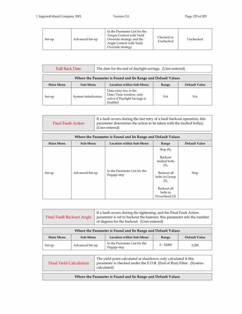
Ingersoll-Rand Company 2001 Version 2.0 Page 129 of 205
Set-up Advanced Set-up
In the Parameter List for the Torque Control with Yield Override strategy and the Angle Control with Yield Override strategy
Checked or Unchecked Unchecked
Fall Back Date The date for the end of daylight savings. (User-entered)
Where the Parameter is Found and Its Range and Default Values
Main Menu Sub-Menu Location within Sub-Menu Range Default Value
Set-up System Initialization
Data entry box in the Date/Time window; only active if Daylight Savings is Enabled
NA NA
Final Fault Action If a fault occurs during the last retry of a fault backout operation, this parameter determines the action to be taken with the faulted bolt(s). (User-entered)
Where the Parameter is Found and Its Range and Default Values
Main Menu Sub-Menu Location within Sub-Menu Range Default Value
Set-up Advanced Set-up In the Parameter List for the Engage step
Stop (0),
Backout faulted bolts
(1),
Backout all bolts in Group
(2),
Backout all bolts in
Powerhead (3)
Stop
Final Fault Backout Angle If a fault occurs during the tightening, and the Final Fault Action parameter is set to backout the fastener, this parameter sets the number of degrees for the backout. (User-entered)
Where the Parameter is Found and Its Range and Default Values
Main Menu Sub-Menu Location within Sub-Menu Range Default Value
Set-up Advanced Set-up In the Parameter List for the Engage step
0 - 32000 3,200
Final Yield Calculation The yield point calculated at shutdown; only calculated if this parameter is checked under the E.O.R. (End of Run) Filter. (System-calculated)
Where the Parameter is Found and Its Range and Default Values

Ingersoll-Rand Company 2001 Version 2.0 Page 130 of 205
Main Menu Sub-Menu Location within Sub-Menu Range Default Value
Set-up System Initialization Behind the E.O.R Filter button
Parameter may be
checked or unchecked
Unchecked
Run Cycle Log If checked (see above) parameter appears in the Cycle Log table
NA NA
Stats Cycle Log If checked (see above) parameter appears in the Cycle Log table
NA NA
Free Speed The maximum speed the tool will turn during fastening. (User-entered)
Where the Parameter is Found and Its Range and Default Values
Main Menu Sub-Menu Location within Sub-Menu Range Default Value
Set-up Quick Set-up Data entry box under Torque Control strategy
Depends on tool selected
90% of the tool’s full free speed
Set-up Quick Set-up Data entry box under Angle Control strategy
Depends on tool selected
90% of the tool’s full free speed
Set-up Advanced Set-up Every step has its own free speed
Depends on tool selected
90% of the tool’s full free speed
Gang Count Some assemblies have multiple bolts that must be fastened in sequence (called a "Gang"). Setting the Gang Count tells the Insight how many tightenings are required to complete the gang assembly. (User-entered)
Where the Parameter is Found and Its Range and Default Values
Main Menu Sub-Menu Location within Sub-Menu Range Default Value
Set-up Advanced Set-up (in Engage step) In the Engage step 1 - 99 1
Group A Group is one or more spindles in a powerhead that have identical fastening steps. Groups can be selected in the Passwords and Powerhead Settings screen. (User-entered)
Where the Parameter is Found and Its Range and Default Values
Main Menu Sub-Menu Location within Sub-Menu Range Default Value
Set-up Password and Powerhead Settings
Drop boxes in the Powerhead Settings portion of the main screen
1 or 2 1
Hall Signal Test During self-testing, the Insight determines if the Hall sensor is operating correctly. (System-calculated)
Where the Parameter is Found and Its Range and Default Values
Main Menu Sub-Menu Location within Sub-Menu Range Default Value
Diagnostics System Test In table under Tool parameters PASS or FAIL NA

Ingersoll-Rand Company 2001 Version 2.0 Page 131 of 205
Jog Angle The number of degrees the tool will turn before exiting the jog step. The tool runs at the softstart speed. (User-entered)
Where the Parameter is Found and Its Range and Default Values
Main Menu Sub-Menu Location within Sub-Menu Range Default Value
Set-up Advanced Set-up In the Parameter List for the Jog Control strategy 1 - 3200 90
Jog Torque If the limit is reached the tool will exit the jog step. (User-entered)
Where the Parameter is Found and Its Range and Default Values
Main Menu Sub-Menu Location within Sub-Menu Range Default Value
Set-up Advanced Set-up In the Parameter List for the Jog Control strategy 0.1 - 9999 0.1
Lamp Test Check boxes to turn the lamp test on or off. This test is used to check the operation of the lights on the tool, the controller cabinet, and on any external light box. (User-entered)
Where the Parameter is Found and Its Range and Default Values
Main Menu Sub-Menu Location within Sub-Menu Range Default Value
Diagnostics Tool test Radio button in the main window NA NA
Language Specifies the language the Insight uses. (User-entered)
Where the Parameter is Found and Its Range and Default Values
Main Menu Sub-Menu Location within Sub-Menu Range Default Value
Set-up System Initialization A drop box in the General window
English, French,
German, Italian, and
Spanish
English
Last Slope The final value of the slope of the torque vs. angle curve. (System-calculated)
Where the Parameter is Found and Its Range and Default Values
Main Menu Sub-Menu Location within Sub-Menu Range Default Value
Set-up System Initialization Behind the E.O.R Filter button Parameter may be
Unchecked

Ingersoll-Rand Company 2001 Version 2.0 Page 132 of 205
checked or unchecked
Run Cycle Log If checked (see above) parameter appears in the Cycle Log table
NA NA
Stats Cycle Log If checked (see above) parameter appears in the Cycle Log table
NA NA
Load Data A button used to upload parameters into the Insight from removable media. (User-entered)
Where the Parameter is Found and Its Range and Default Values
Main Menu Sub-Menu Location within Sub-Menu Range Default Value
Set-up Parameter Transfer and Smart Chip
In the Parameter Transfer portion of the main screen NA NA
Load Software A button used to upload new graphics or motor controller software to the Insight. (User-entered)
Where the Parameter is Found and Its Range and Default Values
Main Menu Sub-Menu Location within Sub-Menu Range Default Value
Set-up Parameter Transfer and Smart Chip
In the Parameter Transfer portion of the main screen NA NA
Max Value The maximum value of the control parameter for the selected configuration. (System-calculated)
Where the Parameter is Found and Its Range and Default Values
Main Menu Sub-Menu Location within Sub-Menu Range Default Value
Run Stats Summary In Parameter List in main window NA NA
Stats Summary In Parameter List in main window NA NA
Meanshift The difference between the mean value and the control point value. (System-calculated)
Where the Parameter is Found and Its Range and Default Values
Main Menu Sub-Menu Location within Sub-Menu Range Default Value
Run Main Under the Var. 1 and Var. 2 drop boxes NA NA
Run Stats Summary In the Parameters List in the NA NA
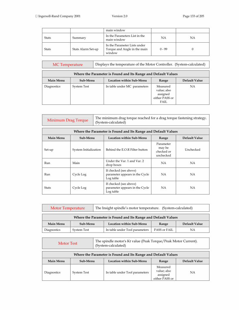
Ingersoll-Rand Company 2001 Version 2.0 Page 133 of 205
main window
Stats Summary In the Parameters List in the main window NA NA
Stats Stats Alarm Set-up In the Parameter Lists under Torque and Angle in the main window
0 - 99 0
MC Temperature Displays the temperature of the Motor Controller. (System-calculated)
Where the Parameter is Found and Its Range and Default Values
Main Menu Sub-Menu Location within Sub-Menu Range Default Value
Diagnostics System Test In table under MC parameters Measured value; also assigned
either PASS or FAIL
NA
Minimum Drag Torque The minimum drag torque reached for a drag torque fastening strategy. (System-calculated)
Where the Parameter is Found and Its Range and Default Values
Main Menu Sub-Menu Location within Sub-Menu Range Default Value
Set-up System Initialization Behind the E.O.R Filter button
Parameter may be
checked or unchecked
Unchecked
Run Main Under the Var. 1 and Var. 2 drop boxes NA NA
Run Cycle Log If checked (see above) parameter appears in the Cycle Log table
NA NA
Stats Cycle Log If checked (see above) parameter appears in the Cycle Log table
NA NA
Motor Temperature The Insight spindle’s motor temperature. (System-calculated)
Where the Parameter is Found and Its Range and Default Values
Main Menu Sub-Menu Location within Sub-Menu Range Default Value
Diagnostics System Test In table under Tool parameters PASS or FAIL NA
Motor Test The spindle motor's Kt value (Peak Torque/Peak Motor Current). (System-calculated)
Where the Parameter is Found and Its Range and Default Values
Main Menu Sub-Menu Location within Sub-Menu Range Default Value
Diagnostics System Test In table under Tool parameters
Measured value; also assigned
either PASS or
NA
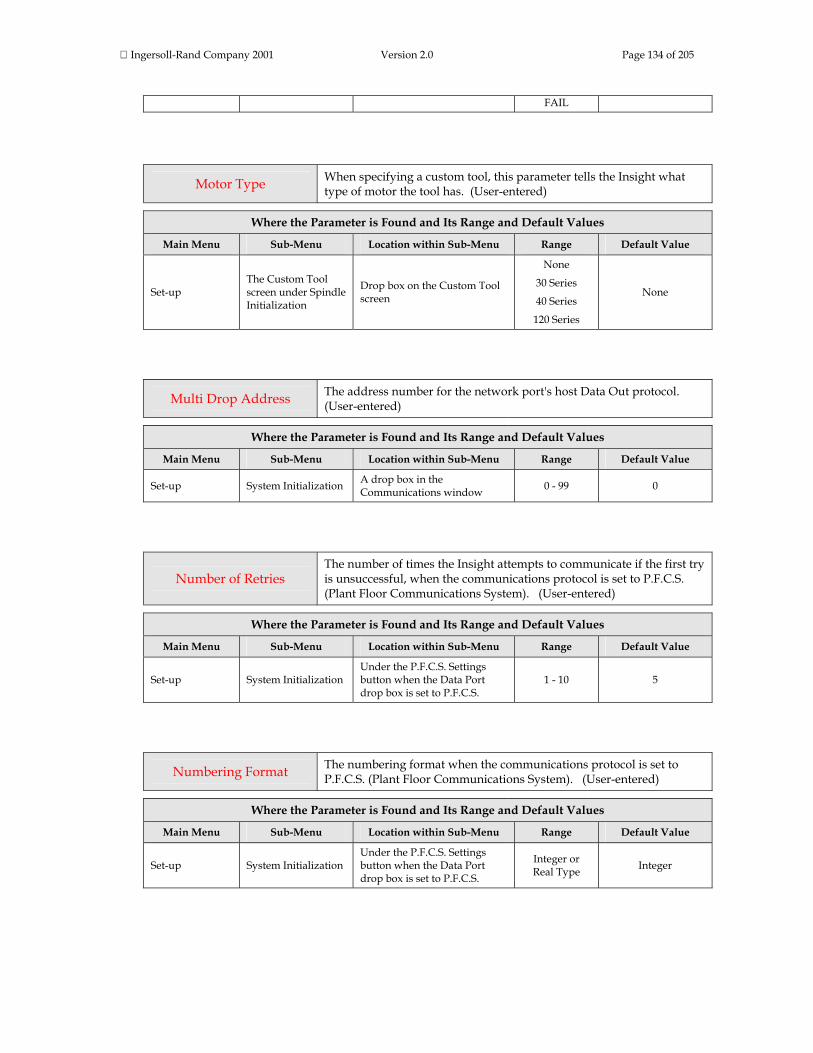
Ingersoll-Rand Company 2001 Version 2.0 Page 134 of 205
FAIL
Motor Type When specifying a custom tool, this parameter tells the Insight what type of motor the tool has. (User-entered)
Where the Parameter is Found and Its Range and Default Values
Main Menu Sub-Menu Location within Sub-Menu Range Default Value
Set-up The Custom Tool screen under Spindle Initialization
Drop box on the Custom Tool screen
None
30 Series
40 Series
120 Series
None
Multi Drop Address The address number for the network port's host Data Out protocol. (User-entered)
Where the Parameter is Found and Its Range and Default Values
Main Menu Sub-Menu Location within Sub-Menu Range Default Value
Set-up System Initialization A drop box in the Communications window 0 - 99 0
Number of Retries The number of times the Insight attempts to communicate if the first try is unsuccessful, when the communications protocol is set to P.F.C.S. (Plant Floor Communications System). (User-entered)
Where the Parameter is Found and Its Range and Default Values
Main Menu Sub-Menu Location within Sub-Menu Range Default Value
Set-up System Initialization Under the P.F.C.S. Settings button when the Data Port drop box is set to P.F.C.S.
1 - 10 5
Numbering Format The numbering format when the communications protocol is set to P.F.C.S. (Plant Floor Communications System). (User-entered)
Where the Parameter is Found and Its Range and Default Values
Main Menu Sub-Menu Location within Sub-Menu Range Default Value
Set-up System Initialization Under the P.F.C.S. Settings button when the Data Port drop box is set to P.F.C.S.
Integer or Real Type Integer
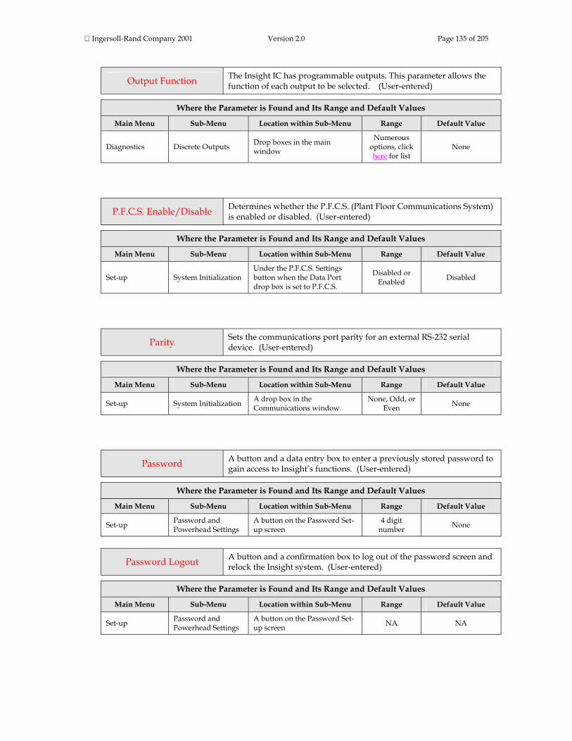
Ingersoll-Rand Company 2001 Version 2.0 Page 135 of 205
Output Function The Insight IC has programmable outputs. This parameter allows the function of each output to be selected. (User-entered)
Where the Parameter is Found and Its Range and Default Values
Main Menu Sub-Menu Location within Sub-Menu Range Default Value
Diagnostics Discrete Outputs Drop boxes in the main window
Numerous options, click here for list
None
P.F.C.S. Enable/Disable Determines whether the P.F.C.S. (Plant Floor Communications System) is enabled or disabled. (User-entered)
Where the Parameter is Found and Its Range and Default Values
Main Menu Sub-Menu Location within Sub-Menu Range Default Value
Set-up System Initialization Under the P.F.C.S. Settings button when the Data Port drop box is set to P.F.C.S.
Disabled or Enabled Disabled
Parity Sets the communications port parity for an external RS-232 serial device. (User-entered)
Where the Parameter is Found and Its Range and Default Values
Main Menu Sub-Menu Location within Sub-Menu Range Default Value
Set-up System Initialization A drop box in the Communications window
None, Odd, or Even None
Password A button and a data entry box to enter a previously stored password to gain access to Insight’s functions. (User-entered)
Where the Parameter is Found and Its Range and Default Values
Main Menu Sub-Menu Location within Sub-Menu Range Default Value
Set-up Password and Powerhead Settings
A button on the Password Set-up screen
4 digit number None
Password Logout A button and a confirmation box to log out of the password screen and relock the Insight system. (User-entered)
Where the Parameter is Found and Its Range and Default Values
Main Menu Sub-Menu Location within Sub-Menu Range Default Value
Set-up Password and Powerhead Settings
A button on the Password Set-up screen NA NA

Ingersoll-Rand Company 2001 Version 2.0 Page 136 of 205
Peak Current The maximum current the tool drew during the fastening cycle. (System-calculated)
Where the Parameter is Found and Its Range and Default Values
Main Menu Sub-Menu Location within Sub-Menu Range Default Value
Set-up System Initialization Behind the E.O.R Filter button
Parameter may be
checked or unchecked
Unchecked
Run Main Var. 1 and Var. 2 drop boxes NA NA
Run Cycle Log If checked (see above) parameter appears in the Cycle Log table
NA NA
Stats Cycle Log If checked (see above) parameter appears in the Cycle Log table
NA NA
Peak Cut-In Torque The maximum torque measured during the cut-in phase (the initial high-torque phase) of the prevailing torque and drag torque strategies. (System-calculated)
Where the Parameter is Found and Its Range and Default Values
Main Menu Sub-Menu Location within Sub-Menu Range Default Value
Set-up System Initialization Behind the E.O.R Filter button
Parameter may be
checked or unchecked
Unchecked
Run Main Var. 1 and Var. 2 drop boxes NA NA
Run Cycle Log If checked (see above) parameter appears in the Cycle Log table
NA NA
Stats Cycle Log If checked (see above) parameter appears in the Cycle Log table
NA NA
Peak Drag Torque The maximum torque measured during the drag torque phase of a drag torque strategy. (System-calculated)
Where the Parameter is Found and Its Range and Default Values
Main Menu Sub-Menu Location within Sub-Menu Range Default Value
Set-up System Initialization Behind the E.O.R Filter button
Parameter may be
checked or unchecked
Unchecked
Run Main Var. 1 and Var. 2 drop boxes NA NA
Run Cycle Log If checked (see above) NA NA

Ingersoll-Rand Company 2001 Version 2.0 Page 137 of 205
parameter appears in the Cycle Log table
Stats Cycle Log If checked (see above) parameter appears in the Cycle Log table
NA NA
Peak Prevailing Torque The maximum torque measured during the prevailing torque phase of a prevailing torque strategy. (System-calculated)
Where the Parameter is Found and Its Range and Default Values
Main Menu Sub-Menu Location within Sub-Menu Range Default Value
Set-up System Initialization Behind the E.O.R Filter button
Parameter may be
checked or unchecked
Unchecked
Run Main Var. 1 and Var. 2 drop boxes NA NA
Run Cycle Log If checked (see above) parameter appears in the Cycle Log table
NA NA
Stats Cycle Log If checked (see above) parameter appears in the Cycle Log table
NA NA
Peak Slope The maximum value of the slope of the torque vs. angle curve. (System-calculated)
Where the Parameter is Found and Its Range and Default Values
Main Menu Sub-Menu Location within Sub-Menu Range Default Value
Set-up System Initialization Behind the E.O.R Filter button
Parameter may be
checked or unchecked
Unchecked
Run Cycle Log If checked (see above) parameter appears in the Cycle Log table
NA NA
Stats Cycle Log If checked (see above) parameter appears in the Cycle Log table
NA NA
Plant Name A data entry box for assigning a plant name or other plant identifier. (User-entered)
Where the Parameter is Found and Its Range and Default Values
Main Menu Sub-Menu Location within Sub-Menu Range Default Value
Set-up System Initialization Data entry box in the General window.
Any alphanumeric
entry (12 characters
max.)
None
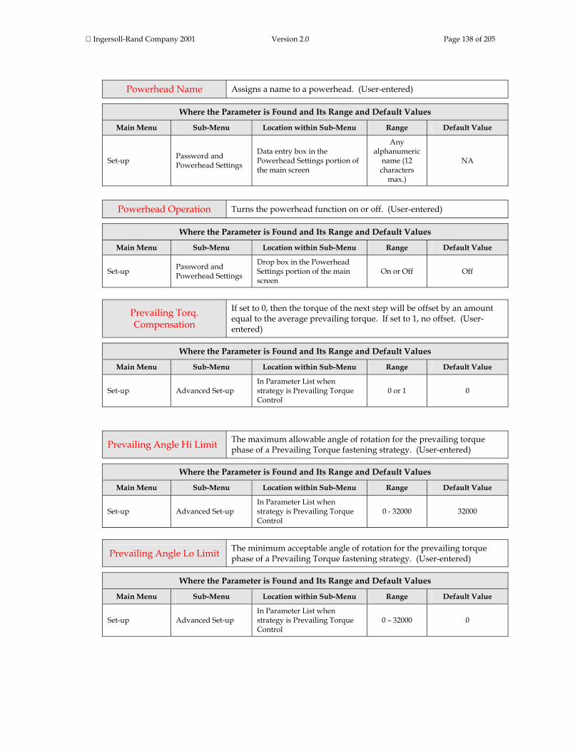
Ingersoll-Rand Company 2001 Version 2.0 Page 138 of 205
Powerhead Name Assigns a name to a powerhead. (User-entered)
Where the Parameter is Found and Its Range and Default Values
Main Menu Sub-Menu Location within Sub-Menu Range Default Value
Set-up Password and Powerhead Settings
Data entry box in the Powerhead Settings portion of the main screen
Any alphanumeric
name (12 characters
max.)
NA
Powerhead Operation Turns the powerhead function on or off. (User-entered)
Where the Parameter is Found and Its Range and Default Values
Main Menu Sub-Menu Location within Sub-Menu Range Default Value
Set-up Password and Powerhead Settings
Drop box in the Powerhead Settings portion of the main screen
On or Off Off
Prevailing Torq. Compensation
If set to 0, then the torque of the next step will be offset by an amount equal to the average prevailing torque. If set to 1, no offset. (User-entered)
Where the Parameter is Found and Its Range and Default Values
Main Menu Sub-Menu Location within Sub-Menu Range Default Value
Set-up Advanced Set-up In Parameter List when strategy is Prevailing Torque Control
0 or 1 0
Prevailing Angle Hi Limit The maximum allowable angle of rotation for the prevailing torque phase of a Prevailing Torque fastening strategy. (User-entered)
Where the Parameter is Found and Its Range and Default Values
Main Menu Sub-Menu Location within Sub-Menu Range Default Value
Set-up Advanced Set-up In Parameter List when strategy is Prevailing Torque Control
0 - 32000 32000
Prevailing Angle Lo Limit The minimum acceptable angle of rotation for the prevailing torque phase of a Prevailing Torque fastening strategy. (User-entered)
Where the Parameter is Found and Its Range and Default Values
Main Menu Sub-Menu Location within Sub-Menu Range Default Value
Set-up Advanced Set-up In Parameter List when strategy is Prevailing Torque Control
0 – 32000 0

Ingersoll-Rand Company 2001 Version 2.0 Page 139 of 205
Prevailing Torque Hi Limit
The maximum permissible torque for the prevailing torque phase of a Prevailing Torque fastening strategy. (User-entered)
Where the Parameter is Found and Its Range and Default Values
Main Menu Sub-Menu Location within Sub-Menu Range Default Value
Set-up Advanced Set-up In Parameter List when strategy is Prevailing Torque Control
0 to maximum rating of tool Depends upon tool
Prevailing Torque Lo Limit
The minimum acceptable torque for the prevailing torque phase of a Prevailing Torque fastening strategy. (User-entered)
Where the Parameter is Found and Its Range and Default Values
Main Menu Sub-Menu Location within Sub-Menu Range Default Value
Set-up Advanced Set-up In Parameter List when strategy is Prevailing Torque Control
0 to Prevailing Torque Hi
value 0
Range The maximum value less the minimum value for a parameter. (System-calculated)
Where the Parameter is Found and Its Range and Default Values
Main Menu Sub-Menu Location within Sub-Menu Range Default Value
Run Main Var. 1 and Var. 2 drop boxes NA NA
Run Stats Summary In Parameter List in main window NA NA
Stats Summary In Parameter List in main window NA NA
Record E.O.R. Data When programming a multi-step tightening, this parameter determines whether or not cycle data is saved for the step. (User-entered)
Where the Parameter is Found and Its Range and Default Values
Main Menu Sub-Menu Location within Sub-Menu Range Default Value
Set-up Advanced Set-up In Parameter List for all the strategies
Enabled or Disabled Disabled
Rem. Tool En / Dis. This parameter allows the tool to be remotely enabled and disabled through the I/O connector; options are On and Off. (User-entered)

Ingersoll-Rand Company 2001 Version 2.0 Page 140 of 205
Where the Parameter is Found and Its Range and Default Values
Main Menu Sub-Menu Location within Sub-Menu Range Default Value
Set-up Spindle Initialization A drop box in the main screen On or Off Off
Re-Torque Angle In Re-torque Mode, the re-torque step will be complete if the angle measured during a re-torque is less than or equal to the value for the re-torque angle. (User-entered)
Where the Parameter is Found and Its Range and Default Values
Main Menu Sub-Menu Location within Sub-Menu Range Default Value
Set-up Advanced Set-up In the Parameter List for the Re-torque Control strategy 0 - 32000 5
Re-Torque Overshoot This parameter is used to adjust the amount of overshoot in the torque value allowed when a previously tightened bolt is re-torqued. (User-entered)
Where the Parameter is Found and Its Range and Default Values
Main Menu Sub-Menu Location within Sub-Menu Range Default Value
Set-up Advanced Set-up In the Parameter List for the Re-torque Control strategy
0 - 9999 torque units 0
Retry Backout Angle If a fault occurs during the tightening, and the Insight is set to retry the fastening, this parameter sets the number of degrees of backout before the retry. (User-entered)
Where the Parameter is Found and Its Range and Default Values
Main Menu Sub-Menu Location within Sub-Menu Range Default Value
Set-up Advanced Set-up In the Parameter List for the Engage step 0 - 32000 90
Retry Backout Speed If a fault occurs during the tightening, and the Insight is set to retry the fastening, this parameter sets the speed of the backout before the retry. (User-entered)
Where the Parameter is Found and Its Range and Default Values
Main Menu Sub-Menu Location within Sub-Menu Range Default Value
Set-up Advanced Set-up In the Parameter List for the Engage step
20 - 100% of the tool's Free
Speed 50%

Ingersoll-Rand Company 2001 Version 2.0 Page 141 of 205
Retry Interval Applies when the Insight is in P.F.C.S. (Plant Floor Communications System) mode. If the Insight is unable to communicate with external devices, this parameter specifies the duration (in seconds) between retries. (User-entered)
Where the Parameter is Found and Its Range and Default Values
Main Menu Sub-Menu Location within Sub-Menu Range Default Value
Set-up System Initialization Under the P.F.C.S. Settings button when the Data Port drop box is set to P.F.C.S.
5 – 60 10
Retry Fault Action If a fault occurs during a operation, this parameter determines the action to be taken with the faulted bolt(s). (User-entered)
Where the Parameter is Found and Its Range and Default Values
Main Menu Sub-Menu Location within Sub-Menu Range Default Value
Set-up Advanced Set-up In the Parameter List for the Engage step
Stop (0),
Backout faulted bolts
(1),
Backout all bolts in Group
(2),
Backout all bolts in
Powerhead (3)
Stop
Save Data A button used to download parameters from the Insight to removable media. (User-entered)
Where the Parameter is Found and Its Range and Default Values
Main Menu Sub-Menu Location within Sub-Menu Range Default Value
Set-up Parameter Transfer and Smart Chip
In the Parameter Transfer portion of the main screen NA NA
Shiftdown Point The point during the final stage of tightening at which the tool shifts to a lower speed to improve accuracy. (User-entered)
Where the Parameter is Found and Its Range and Default Values
Main Menu Sub-Menu Location within Sub-Menu Range Default Value
Set-up Quick Set-up Data entry box # 11 in the main screen when strategy is Torque or Angle control
0 - Maximum torque of tool
50% of Target Torque for Torque Control or 0 (zero) for Angle Control
Set-up Advanced Set-up
In Parameters List under the Step #n Strategy drop box when the strategy is Torque, Angle, or Yield Control
Depends on tool selected
50% of Torque Target

Ingersoll-Rand Company 2001 Version 2.0 Page 142 of 205
Shiftdown Speed The tool's speed during the shiftdown phase. (User-entered)
Where the Parameter is Found and Its Range and Default Values
Main Menu Sub-Menu Location within Sub-Menu Range Default Value
Set-up Quick Set-up Data entry box # 12 in the main screen when strategy is Torque, Angle, or Yield control
Depends on tool selected
30% of tool’s full free speed
Set-up Advanced Set-up One of the parameters under the Step #n Strategy drop box
Depends on tool selected
30% of tool’s full free speed
Shunt Calibration A system test that measures the front-end electronics gain (as % of ideal shunt calibration voltage). (System-calculated)
Where the Parameter is Found and Its Range and Default Values
Main Menu Sub-Menu Location within Sub-Menu Range Default Value
Diagnostics System Test In table under Tool parameters
Measured value; also assigned
either PASS or FAIL
NA
Slope Interval Defines the interval over which the reference slope will be measured. (User-entered)
Where the Parameter is Found and Its Range and Default Values
Main Menu Sub-Menu Location within Sub-Menu Range Default Value
Set-up Advanced Set-up In Parameter List when strategy is Yield Control 0 - 10 0
Sigma The standard deviation (σ); used for statistical calculations. (System-calculated)
Where the Parameter is Found and Its Range and Default Values
Main Menu Sub-Menu Location within Sub-Menu Range Default Value
Run Main Under the Var. 1 and Var. 2 drop boxes NA NA
Run Stats Summary Under the Population Statistics and Sample Statistics drop boxes
NA NA
Stats Summary Under the Population Statistics and Sample Statistics drop boxes
NA NA

Ingersoll-Rand Company 2001 Version 2.0 Page 143 of 205
Snug Torque also called Torque
Threshold
The torque required to seat components in the joint; also the torque point at which angle begins to be measured. (User-entered)
Where the Parameter is Found and Its Range and Default Values
Main Menu Sub-Menu Location within Sub-Menu Range Default Value
Set-up Quick Set-up
Data entry box # 9 in the main screen when strategy is Torque or Angle control, and drop box #10 for Yield Control
0 – maximum of tool
For Torque Control, 20% of Torque
Target
For all other strategies default = 0
Set-up Advanced Set-up
In the Parameters List under the Step #n Strategy drop box when strategy is Torque, Angle, Yield, Prevailing Torque, or Drag Control
0 – maximum of tool
For Torque Control, 20% of Torque
Target
For all other strategies default = 0
Softstart Speed Most handheld tools have two throttle settings. The first (the slower softstart speed) makes it easier for the tool’s socket to engage. (User-entered)
Where the Parameter is Found and Its Range and Default Values
Main Menu Sub-Menu Location within Sub-Menu Range Default Value
Set-up Advanced Set-up In the Engage step under the Step #n Strategy drop box
20 – 100% of the tool’s full
free speed
20% of tool’s full free speed
Spindle Operation This parameter indicates if the start signal is coming from a hand-operated throttle or from an I/O signal (machine mounted). (User-entered)
Where the Parameter is Found and Its Range and Default Values
Main Menu Sub-Menu Location within Sub-Menu Range Default Value
Set-up Spindle Initialization A drop box in the main window
Handheld or Machine Mounted
Handheld
Spindle Status Controls spindle operation. Selecting Enabled allows the tool attached to the spindle to operate, selecting Disabled prevents tool operation. (User-entered)
Where the Parameter is Found and Its Range and Default Values
Main Menu Sub-Menu Location within Sub-Menu Range Default Value
Set-up Spindle Initialization A drop box in the main window
Enabled, or Disabled Enabled
Spring Forward Date The date for the start of daylight savings. (User-entered)
Where the Parameter is Found and Its Range and Default Values
Main Menu Sub-Menu Location within Sub-Menu Range Default Value
Set-up System Initialization Data entry box in the NA NA

Ingersoll-Rand Company 2001 Version 2.0 Page 144 of 205
Date/Time window; only active if Daylight Savings is Enabled
Start Mode
Defines the type of signal initiating tool start. For continuous signal select throttle. Pulse indicates a momentary external signal. Dual requires two switch closures (because some tools require the operator to activate two switches simultaneously to ensure his hands are safely away from the machinery). (User-entered)
Where the Parameter is Found and Its Range and Default Values
Main Menu Sub-Menu Location within Sub-Menu Range Default Value
Set-up Spindle Initialization A drop box in the main window
Throttle, Pulse, or Dual Throttle
Stats From A drop box to select whether the fastening statistics will be displayed for the entire fastening population or for a sample of that population. (User-entered)
Where the Parameter is Found and Its Range and Default Values
Main Menu Sub-Menu Location within Sub-Menu Range Default Value
Statistics Summary A drop box in the main window
Population or Sample
Status A series of Status check boxes that allow the user to make a particular output signal active. (User-entered)
Where the Parameter is Found and Its Range and Default Values
Main Menu Sub-Menu Location within Sub-Menu Range Default Value
Diagnostics Discrete Outputs Check boxes in the main window NA Unchecked
Stop All Spindles on Reject When this box is checked, all spindles in a powerhead will stop as soon as any spindle in the powerhead fails a fastening.. (User-entered)
Where the Parameter is Found and Its Range and Default Values
Main Menu Sub-Menu Location within Sub-Menu Range Default Value
Set-up Password and Powerhead Settings
Check box in the Powerhead Settings portion of the main screen
NA Unchecked
Store Cycle Logs and Master Plots to Flash Disk
A check box to enable cycle logs and master plots to be automatically stored on a flash disk in the PCMCIA slot. (User-entered)
Where the Parameter is Found and Its Range and Default Values

Ingersoll-Rand Company 2001 Version 2.0 Page 145 of 205
Main Menu Sub-Menu Location within Sub-Menu Range Default Value
Set-up Parameter Transfer and Smart Chip
Check box in the Parameter Transfer portion of the main screen
NA Unchecked
Sync Enable If this parameter is enabled, the spindles will be synchronized. (User-entered)
Where the Parameter is Found and Its Range and Default Values
Main Menu Sub-Menu Location within Sub-Menu Range Default Value
Set-up Advanced Set-up In Parameter List for all the strategies except the Engage step.
NA Unchecked
System Name A data entry box for assigning a system name or other system identifier; maximum of 12 letters and numbers. (User-entered)
Where the Parameter is Found and Its Range and Default Values
Main Menu Sub-Menu Location within Sub-Menu Range Default Value
Set-up System Initialization Data entry box in the General window.
Any alphanumeric
entry (12 characters
max.)
None
Target Inspection Angle The number of degrees of rotation required to complete the drag torque phase. (User-entered)
Where the Parameter is Found and Its Range and Default Values
Main Menu Sub-Menu Location within Sub-Menu Range Default Value
Set-up Advanced Set-up In the Parameters List under the Step #n Strategy drop box when strategy is Drag control
0 - 32000 32000
Target Prevailing Angle The number of degrees of rotation required to complete the prevailing torque phase. (User-entered)
Where the Parameter is Found and Its Range and Default Values
Main Menu Sub-Menu Location within Sub-Menu Range Default Value
Set-up Advanced Set-up In the Parameters List under 0 - 32000 32000
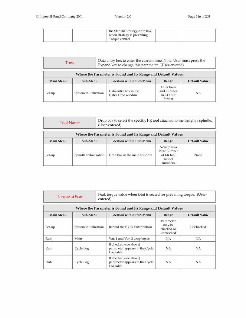
Ingersoll-Rand Company 2001 Version 2.0 Page 146 of 205
the Step #n Strategy drop box when strategy is prevailing Torque control
Time Data entry box to enter the current time. Note: User must press the Expand key to change this parameter. (User-entered)
Where the Parameter is Found and Its Range and Default Values
Main Menu Sub-Menu Location within Sub-Menu Range Default Value
Set-up System Initialization Data entry box in the Date/Time window
Enter hour and minutes
in 24 hour format
NA
Tool Name Drop box to select the specific I-R tool attached to the Insight’s spindle. (User-entered)
Where the Parameter is Found and Its Range and Default Values
Main Menu Sub-Menu Location within Sub-Menu Range Default Value
Set-up Spindle Initialization Drop box in the main window
None plus a large number
of I-R tool model
numbers
None
Torque at Seat Peak torque value when joint is seated for prevailing torque. (User-entered)
Where the Parameter is Found and Its Range and Default Values
Main Menu Sub-Menu Location within Sub-Menu Range Default Value
Set-up System Initialization Behind the E.O.R Filter button
Parameter may be
checked or unchecked
Unchecked
Run Main Var. 1 and Var. 2 drop boxes NA NA
Run Cycle Log If checked (see above) parameter appears in the Cycle Log table
NA NA
Stats Cycle Log If checked (see above) parameter appears in the Cycle Log table
NA NA

Ingersoll-Rand Company 2001 Version 2.0 Page 147 of 205
Torque Filter Removes high frequency noise (ripple) from the torque signal to improve measurement accuracy. This parameter is used primarily for soft (gasketed) joints. For hard joints, select 500 Hz. (User-entered)
Where the Parameter is Found and Its Range and Default Values
Main Menu Sub-Menu Location within Sub-Menu Range Default Value
Set-up Advanced Set-up Drop box in the Engage step 75 - 750 Hz 150 Hz
Torque Hi Limit The maximum permissible torque value for a fastening. (User-entered)
Where the Parameter is Found and Its Range and Default Values
Main Menu Sub-Menu Location within Sub-Menu Range Default Value
Set-up Quick Set-up Data entry box #5 under Torque Control strategy
Depends on tool selected Torque Target +20%
Set-up Quick Set-up Data entry box #7 under Angle Control strategy
Depends on tool selected Maximum of tool
Set-up Quick Set-up Data entry box #6 under Yield Control strategy
Depends on tool selected Maximum of tool
Set-up Advanced Set-up In Parameter List when strategy is Torque Control
Depends on tool selected Torque Target +20%
Set-up Advanced Set-up In Parameter List when strategy is Angle Control
Depends on tool selected Maximum of tool
Set-up Advanced Set-up In Parameter List when strategy is Yield Control
Depends on tool selected Maximum of tool
Set-up Advanced Set-up In Parameter List when strategy is Pretorque Control
Depends on tool selected
Pretorque Target + 20%
Set-up Advanced Set-up In Parameter List when strategy is Backout Control
Depends on tool selected Maximum of tool
Torque Lo Limit The minimum acceptable torque value for a fastening. (User-entered)
Where the Parameter is Found and Its Range and Default Values
Main Menu Sub-Menu Location within Sub-Menu Range Default Value
Set-up Quick Set-up Data entry box #6 under Torque Control strategy
Depends on tool selected Torque Target -20%
Set-up Quick Set-up Data entry box #6 under Angle Control strategy
Depends on tool selected 0
Set-up Quick Set-up Data entry box #7 under Yield Control strategy
Depends on tool selected 0
Set-up Advanced Set-up In Parameter List when strategy is Torque Control
Depends on tool selected Torque Target -20%
Set-up Advanced Set-up In Parameter List when strategy is Angle Control
Depends on tool selected 0
Set-up Advanced Set-up In Parameter List when strategy is Yield Control
Depends on tool selected 0
Set-up Advanced Set-up In Parameter List when C l
Depends on l l d
Pretorque Target –

Ingersoll-Rand Company 2001 Version 2.0 Page 148 of 205
strategy is Pretorque Control tool selected 20%
Torque Overshoot If tightenings are consistently overshooting the Torque Target, the tool will be shut off this many torque units before the Torque Target. (User-entered)
Where the Parameter is Found and Its Range and Default Values
Main Menu Sub-Menu Location within Sub-Menu Range Default Value
Set-up Advanced Set-up In Parameter List when strategy is Torque Control
0 – Torque Target 0
Torque Target The desired final torque for the Torque Control fastening operation. (User-entered)
Where the Parameter is Found and Its Range and Default Values
Main Menu Sub-Menu Location within Sub-Menu Range Default Value
Set-up Quick Set-up Data entry box #4 under Torque Control strategy
Depends on tool selected None
Set-up Advanced Set-up In Parameter List when strategy is Torque Control
Depends on tool selected None
Torque Threshold also called Snug Torque
The torque required to seat components in the joint; also the torque point at which angle begins to be measured. (User-entered)
Where the Parameter is Found and Its Range and Default Values
Main Menu Sub-Menu Location within Sub-Menu Range Default Value
Set-up Quick Set-up
Data entry box # 9 in the main screen when strategy is Torque or Angle control, and data entry box #10 for Yield control
0 – maximum of tool
For Torque Control, 20% of Torque
Target
For all other strategies default = 0
Set-up Advanced Set-up
In the Parameters List under the Step #n Strategy drop box when strategy is Torque, Angle, Yield, Prevailing Torque, or Drag control
0 – maximum of tool
For Torque Control, 20% of Torque
Target
For all other strategies default = 0
Torque Units Use this drop box to select the units the Insight uses to measure torque. (User-entered)

Ingersoll-Rand Company 2001 Version 2.0 Page 149 of 205
Where the Parameter is Found and Its Range and Default Values
Main Menu Sub-Menu Location within Sub-Menu Range Default Value
Set-up Spindle Initialization Drop box in the main window Nm, Ft-lb, In-lb, Kg-cm, or
Kg-m Nm
Transducer Range
Every I-R tool has a generic Transducer Range and (as part of the tool’s final calibration) a specific, measured Transducer Range. The Insight has an internal database so that when you select the I-R tool attached to the spindle, Insight inserts the generic value into the Transducer Range data entry box. You may overwrite this Transducer Range value and insert the tool’s actual measured Transducer Range (located on the tool’s label). (System-calculated AND User-entered)
Where the Parameter is Found and Its Range and Default Values
Main Menu Sub-Menu Location within Sub-Menu Range Default Value
Set-up Spindle Initialization Data entry box in the main window NA Depends on tool
selected
Transmission Mode
Defines how data are exported when the communications protocol is set to P.F.C.S. (Plant Floor Communications System). Options are: Complete Tool Button (data not sent until the operator pushes the tool button), Individual (data sent at the end of each cycle), or Gang Count (data sent at the end of the Gang Count). (User-entered)
Where the Parameter is Found and Its Range and Default Values
Main Menu Sub-Menu Location within Sub-Menu Range Default Value
Set-up System Initialization Under the P.F.C.S. Settings button when the Data Port drop box is set to P.F.C.S.
Complete Tool Button,
Individual, or Gang Count
Complete Tool Button
Tube Nut When enabled, the Insight controller will correctly operate a tube nut tightening tool. (User-entered)
Where the Parameter is Found and Its Range and Default Values
Main Menu Sub-Menu Location within Sub-Menu Range Default Value
Set-up Spindle Initialization Drop box in the main window Enabled or Disabled Disabled

Ingersoll-Rand Company 2001 Version 2.0 Page 150 of 205
Tube Nut Rev. Speed The reversing speed when the Insight is operating a tube nut tightening tool. (User-entered)
Where the Parameter is Found and Its Range and Default Values
Main Menu Sub-Menu Location within Sub-Menu Range Default Value
Set-up Advanced Set-up One of the Engage Parameters under the Step #n Strategy drop box
10 – 30% of tool’s full free
speed
10% of tool’s full free speed
Tube Nut Rev. Threshold Torque value that a tool will shut off in the reverse direction when in Tube Nut Mode. (User-entered
Where the Parameter is Found and Its Range and Default Values
Main Menu Sub-Menu Location within Sub-Menu Range Default Value
Set-up Advanced Set-up One of the Engage Parameters under the Step #n Strategy drop box
10 – 30% of tool’s
maximum torque
10% of tool’s maximum torque
Use Factory Set Angle Constant Value
Use Custom Angle Constant Value
These drop boxes select whether the tool's angle constant value is the factory default value or a user-entered value. This only applies to I-R tools equipped with a Smart Chip. (User-entered)
Where the Parameter is Found and Its Range and Default Values
Main Menu Sub-Menu Location within Sub-Menu Range Default Value
Set-up Parameter Transfer and Smart Chip
Check boxes in the Smart Chip portion of the main screen NA NA
Use Factory Set Transducer Value
Use Custom Transducer Value
These drop boxes select whether the tool's Transducer Range value is the factory default value or a user-entered value. This only applies to I-R tools equipped with a Smart Chip. (User-entered)
Where the Parameter is Found and Its Range and Default Values
Main Menu Sub-Menu Location within Sub-Menu Range Default Value
Set-up Parameter Transfer and Smart Chip
Check boxes in the Smart Chip portion of the main screen NA NA

Ingersoll-Rand Company 2001 Version 2.0 Page 151 of 205
View Password A button that allows a Level 4 user (the highest level of access to the Insight’s functions) to view all the current passwords. (User-entered)
Where the Parameter is Found and Its Range and Default Values
Main Menu Sub-Menu Location within Sub-Menu Range Default Value
Set-up Password and Powerhead Settings
Button on the Password Set-Up screen NA NA
Warn When New Tool Type Required
A checkbox used with tool linking, in which a specific tool is assigned to a configuration. If checked, the Insight will bring up a warning message when a configuration has been selected that has a different tool type than the one previously selected. (User-entered)
Where the Parameter is Found and Its Range and Default Values
Main Menu Sub-Menu Location within Sub-Menu Range Default Value
Set-up The Link Tool screen under Spindle Initialization
Check box on the Link Tool screen NA NA
X-Bar The mean (average) value for the control parameter. (System-calculated)
Where the Parameter is Found and Its Range and Default Values
Main Menu Sub-Menu Location within Sub-Menu Range Default Value
Run Stats Summary In Parameter List in main window NA NA
Stats Summary In Parameter List in main window NA NA
Yield Point % The average decrease in the slope of the torque vs. angle curve that signifies onset of yield. (User-entered)
Where the Parameter is Found and Its Range and Default Values
Main Menu Sub-Menu Location within Sub-Menu Range Default Value
Set-up Quick Set-up Data entry box #4 in the main screen when strategy is Yield Control
20 – 80% NA
Set-up Advanced Set-up
In the Parameter List under the Step #n Strategy drop box when strategy is Torque Control
20 – 80% 50%
Set-up Advanced Set-up In the Parameter List under the Step #n Strategy drop box when strategy is Angle Control
20 – 80% 50%
Set-up Advanced Set-up In the Parameter List under the Step #n Strategy drop box
20 – 80% NA

Ingersoll-Rand Company 2001 Version 2.0 Page 152 of 205
when strategy is Yield Control
This is the end of the Parameters topic. Scroll down to continue your tour or click on another topic at the left. How Do I …? In this section we list a series of commonly asked questions about programming and operating the Insight IC Fastening System with Graphics Display. For each of these questions we provide step-by-step explanations of how to perform the operation. If you have a question about using the Insight, it is probably in this list. You can navigate to specific questions in two ways. First, we have organized the questions into subject headings. Second, we have provided a complete list of questions you can scroll through. To go to the "How do I …?" questions organized by subject, simply scroll down. To go to the complete question list click here. Click on a link below to bring up questions on that subject.
Questions on how to Program Fastening Strategies Questions related to Spindles (Tools) Questions related to Basic Settings (Dates, Times, Torque Units, Passwords, etc.) Questions related to Programming Advanced Tightening Functions Questions related to Communications and Attaching Printers and Peripherals Questions related to Troubleshooting (Installation, Diagnostics, Maintenance,
and Repairs Questions related to Software Versions and Upgrades
FAQ: Program Fastening Strategies How do I program the Insight for the first time? Click on the link below for basic programming instructions.
Quick Start: Be Operational in Minutes
Ingersoll-Rand Company 2001 Version 2.0 Page 153 of 205
How do I program a Torque Control strategy in Quick Set-up?
Prerequisites 1. You must have a spindle (tool) attached.
2. You must have told the software which Ingersoll-Rand spindle is attached, or have a Smart Chip tool connected.
3. You know how to use the directional keys, the Expand key, and the Enter key to navigate on the screen, open a drop box, and select a parameter.
4. You know how to use the numeric keypad to enter data.
Steps 1. Press the Set-up Main Menu key. The Quick Set-up screen will be displayed.
2. Go to the Select Spindle drop box. Spindle 1 is the default value. If you want to use Spindle 1 go to Step 3. If you want to use Spindle 2, open the drop box and select Spindle 2.
3. Go to the Configuration drop box, open it, and select the configuration number you wish to program.
4. The Strategy drop box will display Torque (since this is the default strategy).
5. If you wish to use the learn function to automatically calculate shiftdown point, shiftdown speed and angle limits then select Yes for the learn function. If you wish to enter these values manually then select No.
6. Using the numeric keypad, enter the desired torque value for your fastening operation into the Torque Target data entry box. (Make sure the torque units displayed are the units you want to use. If not, press the Spindle Initialization Sub-Menu key and change the units in the Torque Units drop box.)
7. The Insight software automatically assigns values to the other torque control parameters displayed in the main menu screen. If you want to edit any of these values, navigate to the data entry box and enter a new value using the numeric keypad.
How do I program a Torque Control strategy in Advanced Set-up?
Prerequisites 1. You must have a spindle (tool) attached.
2. You must have told the software which Ingersoll-Rand spindle is attached, or have a Smart Chip tool connected.

Ingersoll-Rand Company 2001 Version 2.0 Page 154 of 205
3. You know how to use the directional keys, the Expand key, and the Enter key to navigate on the screen, open a drop box, and select a parameter.
4. You know how to use the numeric keypad to enter data.
Steps 1. Press the Set-up Main Menu key and then the Advanced Set-up Sub-Menu key.
2. In the Select Spindle drop box select the spindle you want to program.
3. In the Config # drop box select the configuration you want to program.
4. Go to the Engage step drop box and select Engage. (If the Engage parameter default values are acceptable, you can skip to step 6.)
5. Go to the list of parameters just below the Engage step drop box and navigate down through the parameter list. You must enter values (or accept the default values) for the Required Parameters. As appropriate, you may also enter values or accept the default values for the Optional Parameters.
6. Go to the Step #1 Strategy drop box and select Torque.
7. Go to the list of parameters just below the Step #1 Strategy drop box and navigate down through the parameter list. You must enter values (or accept the default values) for the Required Parameters. As appropriate, you may also enter values or accept the default values for the Optional Parameters.
8. If you want to program additional tightening steps, repeat Steps 6 and 7 as appropriate for the desired step.
How do I program an Angle Control strategy in Quick Set-up?
Prerequisites 1. You must have a spindle (tool) attached.
2. You must have told the software which Ingersoll-Rand spindle is attached, or have a Smart Chip tool connected.
3. You know how to use the directional keys, the Expand key, and the Enter key to navigate on the screen, open a drop box, and select a parameter.
4. You know how to use the numeric keypad to enter data.
Steps 1. Press the Set-up Main Menu key. The Quick Set-up screen will be displayed.

Ingersoll-Rand Company 2001 Version 2.0 Page 155 of 205
2. Go to the Select Spindle drop box. Spindle 1 is the default value. If you want to use Spindle 1 go to Step 3. If you want to use Spindle 2, open the drop box and select Spindle 2.
3. Go to the Configuration drop box, open it, and select the configuration number you wish to program.
4. Go to the Strategy drop box and select the Angle strategy.
5. Using the numeric keypad, enter the desired angle value for your fastening operation into the Angle Target data entry box.
6. The Insight software automatically assigns values to the other torque control parameters displayed in the main menu screen. If you want to edit any of these values, navigate to the data entry box and enter a new value using the numeric keypad.
How do I program an Angle Control strategy in Advanced Set-up?
Prerequisites 1. You must have a spindle (tool) attached.
2. You must have told the software which Ingersoll-Rand spindle is attached, or have a Smart Chip tool connected.
3. You know how to use the directional keys, the Expand key, and the Enter key to navigate on the screen, open a drop box, and select a parameter.
4. You know how to use the numeric keypad to enter data.
Steps 1. Press the Set-up Main Menu key and then the Advanced Set-up Sub-Menu key.
2. In the Select Spindle drop box select the spindle you want to program.
3. In the Config # drop box select the configuration you want to program.
4. Go to the Engage step drop box and select Engage. (If the Engage parameter default values are acceptable, you can skip to step 6.)
5. Go to the list of parameters just below the Engage step drop box and navigate down through the parameter list. You must enter values (or accept the default values) for the Required Parameters. As appropriate, you may also enter values or accept the default values for the Optional Parameters.
6. Go to the Step #1 Strategy drop box and select Angle.
Ingersoll-Rand Company 2001 Version 2.0 Page 156 of 205
7. Go to the list of parameters just below the Step #1 Strategy drop box and navigate down through the parameter list. You must enter values (or accept the default values) for the Required Parameters. As appropriate, you may also enter values or accept the default values for the Optional Parameters.
8. If you want to program additional tightening steps, repeat Steps 6 and 7 as appropriate for the desired step.
How do I program a Yield Control strategy in Quick Set-up?
Prerequisites 1. You must have a spindle (tool) attached.
2. You must have told the software which Ingersoll-Rand spindle is attached, or have a Smart Chip tool connected.
3. You know how to use the directional keys, the Expand key, and the Enter key to navigate on the screen, open a drop box, and select a parameter.
4. You know how to use the numeric keypad to enter data.
Steps 1. Press the Set-up Main Menu key. The Quick Set-up screen will be displayed.
2. Go to the Select Spindle drop box. Spindle 1 is the default value. If you want to use Spindle 1 go to Step 3. If you want to use Spindle 2, open the drop box and select Spindle 2.
3. Go to the Configuration drop box, open it, and select the configuration number you wish to program.
4. Go to the Strategy drop box and select the Yield strategy.
5. Using the numeric keypad, enter the desired yield point for your fastening operation into the Yield Point % data entry box (50% recommended).
6. The Insight software automatically assigns values to the parameters displayed in the main menu screen. If you want to edit any of these values, navigate to the data entry box and enter a new value using the numeric keypad.
Note: For Yield Control, I-R recommends setting the torque threshold value to 30 to 60% of the expected yield torque. How do I program a Yield Control strategy in Advanced Set-up?
Prerequisites

Ingersoll-Rand Company 2001 Version 2.0 Page 157 of 205
1. You must have a spindle (tool) attached.
2. You must have told the software which Ingersoll-Rand spindle is attached, or have a Smart Chip tool connected.
3. You know how to use the directional keys, the Expand key, and the Enter key to navigate on the screen, open a drop box, and select a parameter.
4. You know how to use the numeric keypad to enter data.
Steps 1. Press the Set-up Main Menu key and then the Advanced Set-up Sub-Menu key.
2. In the Select Spindle drop box select the spindle you want to program.
3. In the Config # drop box select the configuration you want to program.
4. Go to the Engage step drop box and select Engage. (If the Engage parameter default values are acceptable, you can skip to step 6.)
5. Go to the list of parameters just below the Engage step drop box and navigate down through the parameter list. You must enter values (or accept the default values) for the Required Parameters. As appropriate, you may also enter values or accept the default values for the Optional Parameters.
6. Go to the Step #1 Strategy drop box and select Yield.
7. Go to the list of parameters just below the Step #1 Strategy drop box and navigate down through the parameter list. You must enter values (or accept the default values) for the Required Parameters. As appropriate, you may also enter values or accept the default values for the Optional Parameters.
8. If you want to program additional tightening steps, repeat Steps 6 and 7 as appropriate for the desired step.
How do I program a Backout strategy?
Prerequisites 1. You must have a spindle (tool) attached.
2. You must have told the software which Ingersoll-Rand spindle is attached, or have a Smart Chip tool connected.
3. You know how to use the directional keys, the Expand key, and the Enter key to navigate on the screen, open a drop box, and select a parameter.
4. You know how to use the numeric keypad to enter data.
Steps

Ingersoll-Rand Company 2001 Version 2.0 Page 158 of 205
1. Press the Set-up Main Menu key and then the Advanced Set-up Sub-Menu key.
2. In the Select Spindle drop box select the spindle you want to program.
3. In the Config # drop box select the configuration you want to program.
4. At the appropriate Step #n Strategy drop box select Fault Backout.
5. Go to the list of parameters just below the Step #n Strategy drop box and navigate down through the parameter list. You must enter values (or accept the default values) for the Required Parameters. As appropriate, you may also enter values or accept the default values for the Optional Parameters.
How do I program a Fault Backout strategy?
Prerequisites 1. You must have a fixtured (machine tool) spindle attached.
2. You must have told the software which Ingersoll-Rand spindle is attached, or have a Smart Chip tool connected.
3. You know how to use the directional keys, the Expand key, and the Enter key to navigate on the screen, open a drop box, and select a parameter.
4. You know how to use the numeric keypad to enter data.
Steps 1. Press the Set-up Main Menu key and then the Advanced Set-up Sub-Menu key.
2. In the Select Spindle drop box select the spindle you want to program.
3. In the Config # drop box select the configuration you want to program.
4. Go to the list of parameters just below the Engage Strategy drop box and navigate down through the parameter list. You must enter values for the following parameters: Backout Angle Hi Limit, Final Fault Action, and Final Fault Backout Angle. If you wish to automatically retry the tightening after a fault you will have to program the following parameters: Retry Backout Angle, Retry Backout Speed, Number of Retries, and Retry Action. Note: At least one step must be programmed for fault backout to function.
How do I program a Prevailing Torque Control strategy?

Ingersoll-Rand Company 2001 Version 2.0 Page 159 of 205
Prerequisites 1. You must have a spindle (tool) attached.
2. You must have told the software which Ingersoll-Rand spindle is attached, or have a Smart Chip tool connected.
3. You know how to use the directional keys, the Expand key, and the Enter key to navigate on the screen, open a drop box, and select a parameter.
4. You know how to use the numeric keypad to enter data.
Steps 1. Press the Set-up Main Menu key and then the Advanced Set-up Sub-Menu key.
2. In the Select Spindle drop box select the spindle you want to program.
3. In the Config # drop box select the configuration you want to program.
4. Go to the Step #1 Strategy drop box and select Prevailing Torque.
5. Go to the list of parameters just below the Step #1 Strategy drop box and navigate down through the parameter list. You must enter values (or accept the default values) for the Required Parameters. As appropriate, you may also enter values or accept the default values for the Optional Parameters.
6. If you want to program additional tightening steps, repeat Steps 4 and 5 as appropriate for the desired step.
How do I program a Drag Torque Control strategy?
Prerequisites 1. You must have a spindle (tool) attached.
2. You must have told the software which Ingersoll-Rand spindle is attached, or have a Smart Chip tool connected.
3. You know how to use the directional keys, the Expand key, and the Enter key to navigate on the screen, open a drop box, and select a parameter.
4. You know how to use the numeric keypad to enter data.
Steps 1. Press the Set-up Main Menu key and then the Advanced Set-up Sub-Menu key.
2. In the Select Spindle drop box select the spindle you want to program.
3. In the Config # drop box select the configuration you want to program.
4. Go to the Step #1 Strategy drop box and select Drag Torque.
Ingersoll-Rand Company 2001 Version 2.0 Page 160 of 205
5. Go to the list of parameters just below the Step #1 Strategy drop box and navigate down through the parameter list. You must enter values (or accept the default values) for the Required Parameters. As appropriate, you may also enter values or accept the default values for the Optional Parameters.
6. If you want to program additional tightening steps, repeat Steps 4 and 5 as appropriate for the desired step.
FAQ: Spindles (Tools) How do I select a tool?
Prerequisites 1. You must have a spindle (tool) attached.
2. You do not have a Smart Chip tool connected.
3. You know how to use the directional keys, the Expand key, and the Enter key to navigate on the screen, open a drop box, and select a parameter.
Steps 1. Press the Set-up Main Menu key and then the Spindle Initialization Sub-Menu key.
2. Go to the Tool drop box and select the model number of the I-R tool that is attached to the Insight spindle.
3. If the tool you are using is not in the tool list, select the closest model number. Then go to the TR Value data entry box and enter the actual Transducer Range value for your tool (shown as TR on the tool's label). Then go to the Angle Constant data entry box and enter the actual Angle Constant value for your tool (shown as ASC on the tool's label).
How do I link a tool to a configuration?
Click on the link below for instructions.
Link Tool

Ingersoll-Rand Company 2001 Version 2.0 Page 161 of 205
How do I Clear a step in a configuration?
1. Press the Set-up Main Menu key and then the Advanced Setup Sub-Menu key.
2. Go to the Strategy box of the step you wish to clear and select None.
How do I Clear a configuration?
1. Press the Set-up Main Menu key and then the Advanced Setup Sub-Menu key.
2. Navigate to the button in the lower right hand corner of the screen labeled Clear All Steps and press Enter.
How do I program a custom tool?
Click on the link below for instructions. Custom Tool
How do I program and use a tube nut tool?
A tube nut tool is a tool that has a special attachment that allows it to tighten tube nuts, such as those used in brake line applications. The tube nut attachment has an opening at one end and a socket that is U shaped. To properly use a tube nut tool, the Insight must be programmed specifically for tub nut tool operation.
1. Press the Set-up Main Menu key and then the Spindle Initialization Sub-Menu key.
2. Select the desired spindle from the Spindle drop box.
3. Go to the Tool drop box and select the model number of the I-R tool that is attached to the Insight spindle.
4. Enter the TR value shown on the tool’s calibration label in the Transducer Range data entry box.
5. Enter the ASC value shown on the tool’s calibration label in the Angle Constant data entry box.
6. Select Enabled from the drop box labeled Tube Nut.
You are now programmed to use the tube nut tool. To change the reverse speed of the tube nut tool, change the value in the Tube Nut Rev. Speed parameter data entry box in the Engage step of the Advanced Set-up Sub-Menu. To change the torque threshold at which the tube nut tool reverse motion is stopped, change the

Ingersoll-Rand Company 2001 Version 2.0 Page 162 of 205
value in the Tube Nut Rev. Threshold parameter data entry box in the Engage step of the Advanced Set-up Sub-Menu.
How do I change from a handheld to a fixtured tool (or vise versa)?
A fixtured tool (or machine tool) is one that receives the start or throttle signal remotely through the Insight’s I/O connector on the left-side of the controller. To change from a handheld tool to a fixtured tool, select Machine Mounted from the Spindle Operation drop box on the Spindle Initialization screen. To switch back to handheld mode select Handheld Tool from this drop box.
How do I calibrate a tool to an external transducer?
Click on the link below for calibration instructions.
Auto Calibration How do I remotely enable/disable a tool using a PLC?
1. Press the Set-up Main Menu key and then the Spindle Initialization Sub-Menu key.
2. Select the desired spindle from the Spindle drop box.
3. Go to the Remote Tool En/Dis. drop box and select Enable.
To Disable the Tool
Use the PLC to activate the Spindle Disable input on the left side on the controller.
To Enable the Tool
Use the PLC to activate the Spindle Enable input on the left side on the controller.
NOTE: Only one of these signals can be present at any time FAQ: Basic Settings (Dates, Times, Torque Units, Passwords, etc.)

Ingersoll-Rand Company 2001 Version 2.0 Page 163 of 205
How do I set the system date and time? 1. Press the Set-up Main Menu key and then the System Initialization Sub-Menu key.
2. Go to the Date or Time data entry box then press the Expand key. (To prevent inadvertent changes, these data entry boxes require the Expand key for access.) If entering the date, make sure the date format is as specified in the Date Format drop box.
3. Enter the correct values using the numeric keypad then press Enter.
How do I change the viewable parameters on the Cycle Log screen?
Certain fastening parameters are always displayed on the Cycle Log screen, while others are optional. The optional parameters are those the user chooses to record using the End of Run (E.O.R.) Filter. To select the E.O.R. parameters, follow the steps below.
1. Press the Set-up Main Menu key and then the System Initialization Sub-Menu key.
2. Go to the E.O.R. Filter button and press Enter.
3. Using the Enter key, select the tightening parameters you wish to capture. These parameters will now be displayed on the Cycle Log screen.
How do I change the torque units? 1. Press the Set-up Main Menu key and then the Spindle Initialization Sub-Menu key.
2. Go to the Torque Units drop box then press the Expand key.
3. Select the desired torque units then press Enter.
How do I turn off passwords?
Turning off the password protection allows unrestricted access to all of the Insight’s functions.
1. Press the Set-up Main Menu key and then the Password and Powerhead Settings Sub-Menu key.
2. Go to the Password button, press the Enter key, and enter the Insight’s Level 4 password.
3. Go to Access Lockout Time drop box and press the Expand key.
4. Select OFF then press Enter.

Ingersoll-Rand Company 2001 Version 2.0 Page 164 of 204
How do I change a password? 1. Press the Set-up Main Menu key and then the Password and Powerhead Settings Sub-
Menu key.
2. Go to the Change Password button and press Enter. You will be prompted to enter your password. To change a Level 1, 2, 3, or 4 password you must enter a password of that same level.
3. Enter the new password using the numeric keypad. The password must be a four-digit number.
4. You will be prompted to re-enter the new password.
5. The password is changed. Press any Main Menu key to exit this screen.
How do I Setup Statistical Alarms?
1. Press the Stats Main Menu key and then the Stats Alarm Set-Up Sub-Menu key.
2. Go to the lists of alarm parameters shown in the main window. Scroll through this list, entering the desired values in the parameter drop boxes.
3. Go to the Alarm check box adjacent to the parameter and check the box to turn the alarm parameter on.
How do I use the on-screen Help function?
Click on the link below for instructions.
Help Menus FAQ: Programming Advanced Tightening Functions How do I program and use the Gang Count function? Some assemblies have multiple bolts that must be fastened in sequence; this is called a "Gang." For example, if you have a four-bolt assembly you will set the Gang Count to 4. Insight will then keep track of each fastening and when all four fastenings have been completed within specification, a "Gang Complete" message will appear on the display screen.
To Set the Gang Count

Ingersoll-Rand Company 2001 Version 2.0 Page 165 of 204
1. Press the Set-up Main Menu key and then the Advanced Set-up Sub-Menu key.
2. Select the desired spindle and configuration.
3. Go to the list of parameters just below the Engage step drop box, navigate down through the parameter list, and enter the gang count value into the parameter Gang Count.
To Display the Gang Count
To display the current status of the Gang Count during a fastening select Gang Count from the Var. 1 and/or Var. 2 drop box on the Run Main screen.
To Reset the Gang Count
During a Gang Count fastening operation, if one of the tightenings fails the count must be reset to one. There are two ways to reset the Gang Count.
1. From the Run Main screen, pressing 0 (zero) then Enter resets the count for Spindle 1. Pressing 00 and Enter resets the count for Spindle 2.
2. The Gang Count can be reset externally by activating the Gang Reset input on the left side on the controller.
Gang Count Complete
The Insight provides two indications when the Gang Count is successfully completed.
1. "Gang Complete" displays on the Run Main screen.
2. Gang Complete output becomes active to provide an external signal.
How do I program and use the Auto Increment function? Auto Increment (often used in conjunction with the Gang Count function) is one of the options in the Engage step box in the Advanced Setup screen. To program this function go to the Engage Step of the first configuration in the sequence desired and enter the configuration number you wish this configuration to go to in the parameter Auto Increment. For example, to make Configuration 1 auto increment to Configuration 5, enter 5 into Configuration 1's Auto Increment parameter. Then go to Configuration 5 and enter into its Auto Increment the next configuration in the sequence, and so on and so on. The last configuration in the

Ingersoll-Rand Company 2001 Version 2.0 Page 166 of 204
sequence should have the first configuration number's value in its auto increment parameter, so that a loop is created.
If you select this option, when the Insight begins a fastening sequence the controller will start from the programmed configuration with the lowest configuration number. Upon completing that configuration, it will move to the next programmed configuration in ascending order. The system will continue to step through all programmed configurations until it reaches the configuration with the highest configuration number. After completing that configuration the system will return to the first programmed configuration for the next cycle. Note that it is possible to have multiple auto increments in one system. To select between different auto increment chains, select a configuration in that chain.
Auto Increment Reset
During an Auto Increment fastening sequence, if one of the fastenings fails and the part is rejected, the Auto Increment must be reset to the lowest configuration number. There are two ways to reset the Auto Increment.
1. From the Run Main screen, pressing 000 (zero three times) then Enter resets the count for Spindle 1. Pressing 0000 and Enter resets the count for Spindle 2.
3. The Auto Increment can be reset externally by activating the Config Reset input on the left side on the controller.
How do I assign a name to a configuration? It is often useful to assign a meaningful name to a fastening configuration number so that it is easier to recall the purpose of the configuration. (Such as: RIGHT DOOR, PRELIM ASSY, ACCESS PANEL, etc.) 1. Press the Set-up Main Menu key and then the Advanced Set-up Sub-Menu key.
2. Go to the Select Spindle drop box and select the spindle whose configuration you are naming.
3. Go to the Config # drop box and select the configuration you want to name.
4. Go to the Config Name data entry box and enter the configuration name (up to 12 alphanumeric characters) using the numeric keypad.

Ingersoll-Rand Company 2001 Version 2.0 Page 167 of 204
How do I use the S.M.A.R.T Windows function to calculate limits?
S.M.A.R.T. stands for Self Moving Automatic Range Test. Click on the link below for instructions.
S.M.A.R.T. Windows Discussion FAQ: Questions related to Communications and Attaching Printers and Peripherals How do I send End of Run data via the serial port at the end of each cycle?
1. Press the Set-up Main Menu key and then the System Initialization Sub-Menu key.
2. Go to the Data Port drop box and select COM1.
3. Go to the Comm Protocol drop box and select E.O.R Data Out.
4. Make sure the Baud Rate, Parity, # of Stop Bits, and Bits per Character are at the desired settings.
You will now get one line of tightening data out of the serial port labeled "Auxiliary Serial" for each cycle run. The format of the data sent can be modified by using the Edit Data Format function under the Stats Main Menu and Export Sub-Menu, and checking the box labeled Make E.O.R. Data Out Same Format. How do I connect and use a socket tray?
Click on the link below for Insight installation instructions.
Socket Tray Connection and Setup How do I switch configurations using a PLC?
Ingersoll-Rand Company 2001 Version 2.0 Page 168 of 204
1. Press the Set-up Main Menu key and then the Spindle Initialization Sub-Menu key.
2. If your PLC is switching only the first eight configurations, go to Step 4 below. If your PLC is switching configurations beyond configuration eight, go to Step 3 below.
3. Go to the Config. Select. Type drop box and select External Binary, then go to Step 5.
4. Go to the Config. Select. Type drop box and select External Discrete, then go to Step 5.
5. Insight programming for PLC operation is now complete. See information below on how to connect your PLC.
If you selected External Binary in the Config. Select. drop box then you will use configuration inputs 1 through 5 (on the I/O connector) as a binary number to switch all 32 configurations. If you selected External Discrete operation, then you will use the inputs 1 through 8 to directly select the desired configuration.
How do I connect the Insight IC to a bar code scanner?
The Insight is compatible with bar code readers that have a serial output and send ASCII text characters.
1. Connect your bar code scanner via a standard 9-pin serial cable to a communications (comm.) port located on the left-hand side of the Insight controller (the ports are labeled "10101").
2. Press the Set-up Main Menu key and then the System Initialization Sub-Menu key.
3. Go to the Data Port drop box and select the communications port you whish to connect the bar code scanner too.
4. Go to the Comm. Protocol drop box and select Bar Code.
5. As necessary, adjust the settings for Baud Rate, Parity, # of Stop Bits, and Bits Per Character to match those settings on the Bar code reader.
6. Go the button labeled Settings and press the Enter key
7. Select the spindle to attach the bar code scans to.
8. Go to the Bar Code Length data entry box and enter the number of characters in the bar code using the numeric keypad.

Ingersoll-Rand Company 2001 Version 2.0 Page 169 of 204
9. If you whish to select configurations using the data from the Bar code scan, enter values in the Data From and To entry boxes along with Criteria for each configuration.
10. Press the Assign then the OK button to save your changes.
11. Press the Run Main Menu key. Go to the appropriate variable box (Var. 1 or Var. 2) and select Bar Code.
12. Use the bar code scanner to scan a code and then run a cycle with the tool. The scan data should appear in the variable box on the Run Main screen as well as in the Cycle Log.
How do I attach a serial printer?
Click on the link below for instructions.
Serial Printer Connection and Setup How do I attach a parallel printer?
Click on the link below for instructions.
Parallel Printer Connection and Setup How do I attach a PC?
Click on the link below for instructions.
Computer Connection and Setup via the Serial Port How do I check the status of inputs from the I/O connector? 1. Press the Diagnostics Main Menu key and then the Discrete Inputs Sub-Menu key.
2. Each input that is active is shown in real time during the fastening cycle.
How do I save program parameters to a floppy disk?
1. Press the Set-up Main Menu key and then the Parameter Transfer and Smart Chip Sub-Menu key.
2. Ensure that a formatted floppy disk is in the floppy drive.
3. Select Floppy Disk from the Save Data section of the Parameter Transfer portion of the screen.

Ingersoll-Rand Company 2001 Version 2.0 Page 170 of 204
4. Navigate to the Save Data button, press Enter, and enter in a file name using the numeric keypad.
How do I load program parameters from a floppy disk?
1. Press the Set-up Main Menu key and then the Parameter Transfer and Smart Chip Sub-Menu key.
2. Ensure that a floppy disk containing program sets is in the floppy drive.
3. Select Floppy Disk from the Load Data section of the Parameter transfer portion of the screen.
4. Navigate to the Load Data button, press Enter, and enter in a file name using the numeric keypad.
FAQ: Questions related to Troubleshooting (Installation, Diagnostics, Maintenance, and Repairs) How do I install the Insight controller in the workspace? Click on the link below for Insight installation instructions.
Mounting the Insight Enclosure How do I replace a Motor Controller?
This process is easier if the Insight IC controller is placed on its back on a flat level surface before beginning this procedure.
1. Turn off the system using the rotary Main Power Switch on the right-hand side of the controller.
2. Unplug the power cord then unlock and open the front door.
3. Disconnect the five connectors on the Motor Controller.
4. Unfasten the four screws securing the Motor Controller to the heat sink (one screw in each corner).
5. Use a screwdriver to pry the Motor Controller from the heat sink.
6. Place the new Motor Controller over the heat sink and fasten the four screws.
7. Re-connect the five connectors.

Ingersoll-Rand Company 2001 Version 2.0 Page 171 of 204
How do I conduct diagnostics on a connected tool? 1. Press the Diagnostics Main Menu key and the System Test Sub-Menu is displayed.
2. Go to the Start Test button and press Enter. The Insight will test the tool and display the results on the left-hand side of the main screen.
3. To save the test results go to the Save Results button and press Enter. The Insight will save the test results on the right-hand side of the main screen.
FAQ: Questions related to Software Versions and Upgrades How do I check the application software version I am using?
1. Press the Set-up Main Menu key and then the System Initialization Sub-Menu key.
2. The version number is displayed in the General window next to the words "Version Insight."
How do I check the Motor Controller Electronics (MCE) software version I am using?
1. Press the Set-up Main Menu key and then the System Initialization Sub-Menu key. 2. Navigate to the MCE Version button and press Enter. The Complete List of "How do I …?" Questions How do I …?
1. Program the Insight for the first time?
2. Program a Torque Control strategy in Quick Set-up?
3. Program a Torque Control strategy in Advanced Set-up?
4. Program an Angle Control strategy in Quick Set-up?

Ingersoll-Rand Company 2001 Version 2.0 Page 172 of 204
5. Program an Angle Control strategy in Advanced Set-up?
6. Program a Yield Control strategy in Quick Set-up?
7. Program a Yield Control strategy in Advanced Set-up?
8. Program a Backout strategy?
9. Program a Fault Backout strategy?
10. Program a Prevailing Torque Control strategy?
11. Program a Drag Torque Control strategy?
12. Select a tool?
13. Link a tool to a configuration?
14. Clear a step in a configuration?
15. Clear a configuration?
16. Program a custom tool?
17. Program and use a tube nut tool?
18. Change from a handheld to a fixtured tool (or vise versa)?
19. Calibrate a tool to an external transducer?
20. Remotely enable/disable a tool using a PLC?
21. Set the system date and time?
22. Change the viewable parameters on the Cycle Log screen?
23. Change the torque units?
24. Turn off passwords?
25. Change a password?
26. Setup Statistical Alarms?
27. Use the on-screen Help function?
28. Program and use the Gang Count function?
29. Program and use the Auto Increment function?
30. Assign a name to a configuration?
31. Use the S.M.A.R.T Windows function to calculate limits?
32. Send End of Run data via the serial port at the end of each cycle?
33. Connect and use a socket tray?
34. Switch configurations using a PLC?
35. Connect the Insight to a bar code scanner?

Ingersoll-Rand Company 2001 Version 2.0 Page 173 of 204
36. Attach a serial printer?
37. Attach a parallel printer?
38. Attach a PC?
39. Check the status of inputs from the I/O connector?
40. Save program parameters to a floppy disk?
41. Load program parameters to a floppy disk?
42. Install the Insight controller in the workspace?
43. Replace a Motor Controller?
44. Conduct diagnostics on a connected tool?
45. Check the application software version I am using?
46. Check the Motor Controller Electronics (MCE) software version I am using? This is the end of How Do I …? section. To go to the next section of this manual click on the arrow below, or click on another topic at the left. Fastening Fundamentals Precision fastening is the process of applying energy to a fastener via a DC electric torque wrench (called a spindle) in a highly controlled fashion, in order to achieve an optimum clamp load. The Insight Fastening Control System is the device that controls the spindle. When a bolt is tightened most of the energy input (typically over 90%) is needed to overcome friction in the threads and elsewhere. Only about 10% is actually used to achieve the clamp load. The amount of friction that must be overcome before proper clamping is achieved can be highly variable. Since friction in the system is both large and variable, it takes a very sophisticated system like Insight to monitor all the tightening parameters and achieve accurate and reproducible fastening. There are a variety of ways to control fastening, all involve measuring the torque applied to the fastener and the fastener's angular rotation. Insight comes ready to operate in 13 modes or fastening strategies. To go to a brief explanation of a particular strategy click on the link below, or continue your tour and these strategies will be introduced in the sequence shown.

Ingersoll-Rand Company 2001 Version 2.0 Page 174 of 204
Engage step
Torque Control strategy
Torque Control with Yield Override strategy
Angle Control strategy
Angle Control with Yield Override strategy
Yield Control strategy
Re-torque Control strategy
Backout Control strategy
Delay Control strategy
Jog Control strategy
Prevailing Torque Control strategy
Drag Torque Control strategy
Bypass strategy
By controlling a very large number of spindle variables, Insight can achieve highly accurate fastening regardless of the tightening mode used. In addition, by using Insight's advanced programming features you can readily combine these modes to create many specialized tightening strategies. Following is a brief explanation of each of these tightening strategies. The torque vs. angle curve (called the tightening curve or signature) is also shown, where appropriate. These signatures call attention to the important parameters or control points for each strategy. Engage Step Strictly speaking, the Engage step is not a tightening strategy. Rather it is a step that precedes the tightening strategy and allows the user to specify exactly how the tool will engage the fastener. For example, in the Engage step the user can set the direction the tool turns to tighten (does the fastener have right-hand or left-hand threads?), the speed at which the tool runs down the fastener prior to tightening, the speed at which the tools backs-out if a fault occurs, and so on.

Ingersoll-Rand Company 2001 Version 2.0 Page 175 of 204
There are about 20 separate Engage parameters, some of which are quite complex. The parameters are explained them in detail in the Engage Parameters topic in the Advanced Setup section. Torque Control Strategy Torque is a measure of force (in units of pounds or Newtons) applied over a distance (in units of inches, feet, or meters). Thus, in the Torque Control mode the fastener is tightened to a predetermined torque value as measured by the torque transducer in the spindle. A check on the final angle of fastener rotation is also provided to detect bad tightenings, such as crossed or stripped threads. The tightening curve for torque control strategy is shown below. Click on each parameter with a red highlight to learn its function.

Ingersoll-Rand Company 2001 Version 2.0 Page 176 of 204
Torque Control with Yield Override Strategy This is part of the Torque Control mode described immediately above, but in this case an additional check is made during tightening to detect the onset of fastener yield. (Yield is plastic deformation of the fastener, and is described below in Yield Control Strategy.) In this mode, tightening is complete when the controller either reaches the predetermined torque value or detects fastener or joint yield. If yield is reached, the user can program whether this tightening is considered a pass or a fail. Angle Control Strategy Angle Control mode works by turning the fastener through a pre-determined angle. Actually this is a two-step process. First a torque is applied to consolidate ("snug") the fastener. Then the fastener is turned through the specified angle. Determining the snug (torque threshold) and final angle parameters requires application testing in order to develop a thorough knowledge of the variations in fastener properties. The tightening curve for angle control strategy is shown below. Click on each parameter with a red highlight to learn its function.
Torq
ue
Torque High Limit
Torque Low Limit

Ingersoll-Rand Company 2001 Version 2.0 Page 177 of 204
Angle Control with Yield Override Strategy This is the part of the Angle Control mode described immediately above, but in this case an additional check is made during tightening to detect the onset of fastener yield. (Yield is plastic deformation of the fastener, and is described below in Yield Control Strategy.) In this mode, tightening is complete when the controller either reaches the predetermined angular rotation or detects fastener or joint yield. If yield is reached, the user can program whether this tightening is considered a pass or a fail.

Ingersoll-Rand Company 2001 Version 2.0 Page 178 of 204
Yield Control Strategy In Yield Control mode the fastener is tightened until there is actual yield (plastic deformation) of the fastener, as measured by monitoring torque and angle tightening parameters. Yield control tightening provides the maximum clamp load for the joint. Also, yield control permits very consistent clamp loads, making it appropriate for critical fastening, such as engine connecting rod and head bolts. The tightening curve for yield control mode is shown below. Click on each parameter with a red highlight to learn its function. Note: Application testing is required to ensure the joint is suitable for yield control. % of Peak
Gradient
TToorrqquuee GGrraaddiieenntt
Bolt Yield Point
TToorrqquuee
Torq
ue
(Clam
p Lo
ad)
Torque High Limit
Torque Low Limit
Angle High Limit
Angle Low Limi
Angle Into Yield
Snug Torque

Ingersoll-Rand Company 2001 Version 2.0 Page 179 of 204
Re-torqe Control Strategy Sometimes a fastener will relax after it is tightened. In the Re-torque Control mode the Insight controller reapplies torque to take up relaxation in the joint. This mode can only be used following a Torque Control or Angle Control strategy. The re-torque set point is automatically set at either the Torque Control strategy’s target torque value, or the peak torque attained if this step follows an Angle Control strategy. In this mode, the Insight re-tightens the fastener to the same torque value, subject to certain limiting parameters. Backout Control Strategy In many instances a fastener is first tightened, then untightened (backed out), then retightened. This process is often used with fasteners that have a compressible gasket. The initial tightening helps deform and consolidate the gasket. The final tightening step is then used to both fully seat the gasket as well as achieve the correct clamp load. This strategy can also be used to pre-condition (clean/chase) the internal threads prior to final tightening. Backout Control strategy is simply the backout step in the process described above. There is no tightening curve for backout mode, since it is only the untightening portion of a larger fastening strategy. Delay Control Strategy Delay strategy simply allows a time delay to be programmed into the fastening sequence.

Ingersoll-Rand Company 2001 Version 2.0 Page 180 of 204
Jog Control Strategy Jog Control mode allows the user to run the Insight at a slow speed for a predetermined maximum angle so that the tool’s socket can easily find and engage the fastener. The jog speed is actually set during the Engage step, but the angle is set here. The jog step continues until either the jog angle or jog torque is reached. Prevailing Torque Control Strategy Prevailing Torque Control mode is used with certain specialized fasteners, such as those with nylon locking inserts or tri-lobular fasteners that are self-tapping or thread-forming. When these fasteners are tightened they encounter an initial period of high torque even before the fastener applies any clamp load. Insight can be programmed to apply the correct amount of initial torque to overcome the fastener resistance, and then continue to apply torque to achieve the proper clamp load. Prevailing torque mode refers only to the strategy required to overcome the fastener resistance; another strategy must always follow prevailing torque to perform the final tightening. The tightening curve for prevailing torque mode is shown below. Click on each parameter with a red highlight to learn its function.
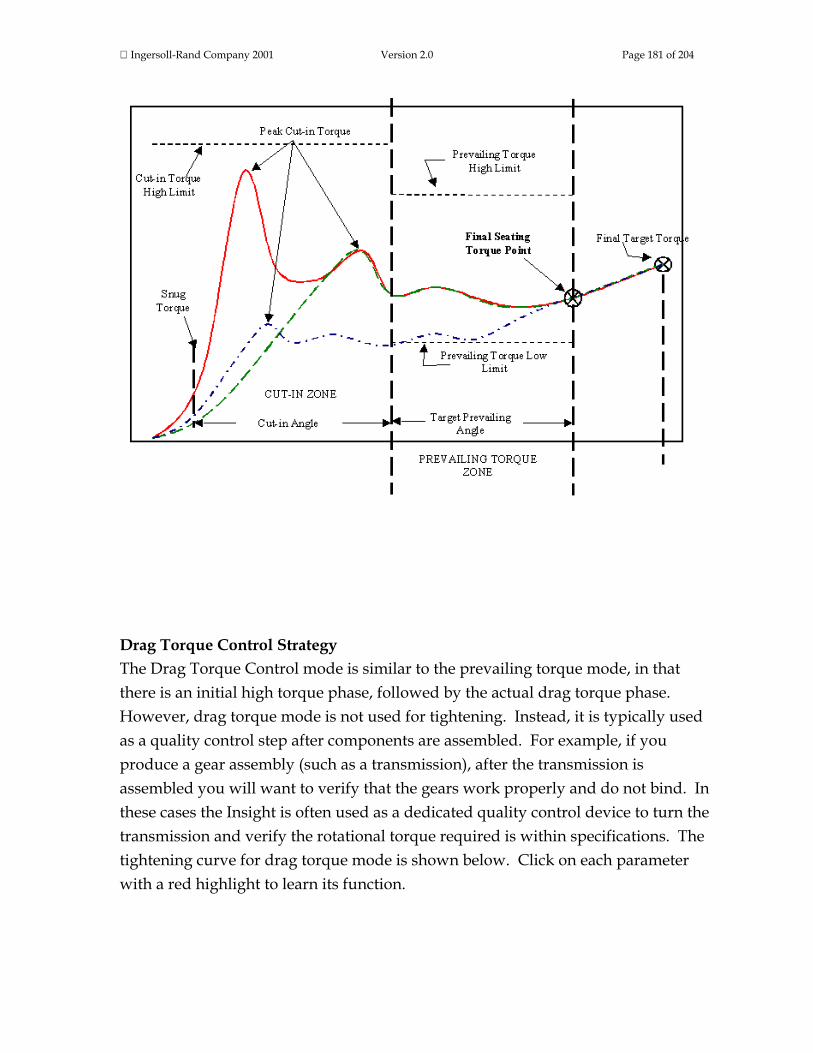
Ingersoll-Rand Company 2001 Version 2.0 Page 181 of 204
Drag Torque Control Strategy The Drag Torque Control mode is similar to the prevailing torque mode, in that there is an initial high torque phase, followed by the actual drag torque phase. However, drag torque mode is not used for tightening. Instead, it is typically used as a quality control step after components are assembled. For example, if you produce a gear assembly (such as a transmission), after the transmission is assembled you will want to verify that the gears work properly and do not bind. In these cases the Insight is often used as a dedicated quality control device to turn the transmission and verify the rotational torque required is within specifications. The tightening curve for drag torque mode is shown below. Click on each parameter with a red highlight to learn its function.

Ingersoll-Rand Company 2001 Version 2.0 Page 182 of 204
Bypass Strategy The Bypass strategy is unique, in that it is either off or on, it has no selectable parameters. The bypass mode applies only to powerheads. It is used to allow a powerhead to operate with different spindles depending upon the tightening configuration selected. When a powerhead is programmed with different configurations, unwanted spindles can be bypassed so only the desired spindles are used. This is the end of Fastening Fundamentals. To go to the next section of this manual click on the arrow below, or click on another topic at the left. Contact Ingersoll-Rand The Fastener Tightening Systems group of Ingersoll-Rand wants you to achieve excellence in fastening and component assembly, and we are ready to help you in any way we can. Contact us for any type of assistance, including
• technical support • fastening training programs • warranty service

Ingersoll-Rand Company 2001 Version 2.0 Page 183 of 204
• spare parts or repair services • application testing.
Our web site (www.irtools.com/fts) is a comprehensive source of information, and you can also e-mail your questions or comments to us via the web site or at [email protected]. In addition, you can reach us by mail, telephone, or fax at our USA, Latin America, Europe, and Asia Pacific offices:
USA
Ingersoll-Rand Company Tool and Hoist Division Fastener Tightening Systems 1467 State Highway 31 South Annendale, NJ 08801 USA Telephone: (908) 238-7000 Fax: (908) 238-7051
Latin America Ingersoll-Rand Company Tool and Hoist Division 730 N. W. 107th Avenue Miami, FL 33172-3107 Telephone: (305) 559-0500 Fax: (305) 559-7505
Europe Ingersoll-Rand Company FTS Division Swan Lane Hindley Green Wigan WN2 4EZ United Kingdom Telephone: (44) 01942 257131 Fax: (44) 01942 502181
Asia Pacific Ingersoll-Rand Company 23/F, 625 King’s Road North Point Hong Kong Telephone: (852) 2528-7338

Ingersoll-Rand Company 2001 Version 2.0 Page 184 of 204
Fax: (852) 2529-5976
Register Your Insight System To get the most from your Ingersoll-Rand Insight fastening control system you should register the product. As a registered user, you and your company will receive notification of enhancements and software upgrades, maintenance bulletins, safety announcements, etc. You will need the following information when you register:
• Product Model Number • Product Serial Number (also called Date Code)
This information is located on the label on the right side of the Insight controller, next to the rotary power switch. To register your system mail in the Registration Card that was included in the shipping carton. Product Warranty Information In general, Ingersoll-Rand Insight Fastening Control Systems are warranted for 12 months after installation or 15 months from the date of purchase, whichever occurs first. Since warranty terms are subject to change, refer to the specific warranty that came with your system. If you have questions about your warranty, or need warranty service, contact Ingersoll-Rand and we will promptly pursue corrective action. This is the end of the Contact Ingersoll-Rand section. To go to the next section of this manual click here, or click on another topic at the left.

Ingersoll-Rand Company 2001 Version 2.0 Page 185 of 204
Services: System Specifications
Insight Technical Specifications The specifications for the Insight IC Tightening System are shown below.
Property Value
Measurement Accuracy ±0.2% of torque full scale ±1 count of angle
Measurement Resolution ±0.025% of torque full scale
Torque Transducer Bridge Excitation ±5V DC standard
Torque Transducer Zero Offset/Drift Compensation ±0.4% of full scale
Input Signal Sensitivity 2.0 mV/V
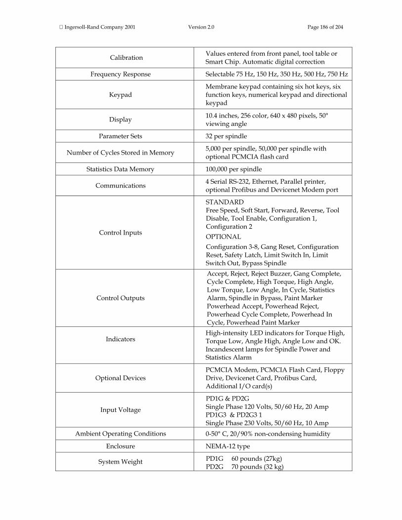
Ingersoll-Rand Company 2001 Version 2.0 Page 186 of 204
Calibration Values entered from front panel, tool table or Smart Chip. Automatic digital correction
Frequency Response Selectable 75 Hz, 150 Hz, 350 Hz, 500 Hz, 750 Hz
Keypad Membrane keypad containing six hot keys, six function keys, numerical keypad and directional keypad
Display 10.4 inches, 256 color, 640 x 480 pixels, 50° viewing angle
Parameter Sets 32 per spindle
Number of Cycles Stored in Memory 5,000 per spindle, 50,000 per spindle with optional PCMCIA flash card
Statistics Data Memory 100,000 per spindle
Communications 4 Serial RS-232, Ethernet, Parallel printer, optional Profibus and Devicenet Modem port
Control Inputs
STANDARD Free Speed, Soft Start, Forward, Reverse, Tool Disable, Tool Enable, Configuration 1, Configuration 2 OPTIONAL Configuration 3-8, Gang Reset, Configuration Reset, Safety Latch, Limit Switch In, Limit Switch Out, Bypass Spindle
Control Outputs
Accept, Reject, Reject Buzzer, Gang Complete, Cycle Complete, High Torque, High Angle, Low Torque, Low Angle, In Cycle, Statistics Alarm, Spindle in Bypass, Paint Marker Powerhead Accept, Powerhead Reject, Powerhead Cycle Complete, Powerhead In Cycle, Powerhead Paint Marker
Indicators
High-intensity LED indicators for Torque High, Torque Low, Angle High, Angle Low and OK. Incandescent lamps for Spindle Power and Statistics Alarm
Optional Devices PCMCIA Modem, PCMCIA Flash Card, Floppy Drive, Devicenet Card, Profibus Card, Additional I/O card(s)
Input Voltage
PD1G & PD2G Single Phase 120 Volts, 50/60 Hz, 20 Amp
PD1G3 & PD2G3 1 Single Phase 230 Volts, 50/60 Hz, 10 Amp
Ambient Operating Conditions 0-50° C, 20/90% non-condensing humidity
Enclosure NEMA-12 type
System Weight PD1G 60 pounds (27kg) PD2G 70 pounds (32 kg)

Ingersoll-Rand Company 2001 Version 2.0 Page 187 of 204
PD1G3 80 pounds (36 kg) PD2G3 90 pounds (41 kg)
Insight Dimensional Drawings Below are the dimensional drawings for the Insight one and two spindle controllers. Information on recommended mounting hardware is also provided on the drawings.
PD1G, PD2G, PD1G3 and PD2G3 Top View

Ingersoll-Rand Company 2001 Version 2.0 Page 188 of 204

Ingersoll-Rand Company 2001 Version 2.0 Page 189 of 204
PD1G and PD2G Front View
PD1G3 and PD2G3 Front View
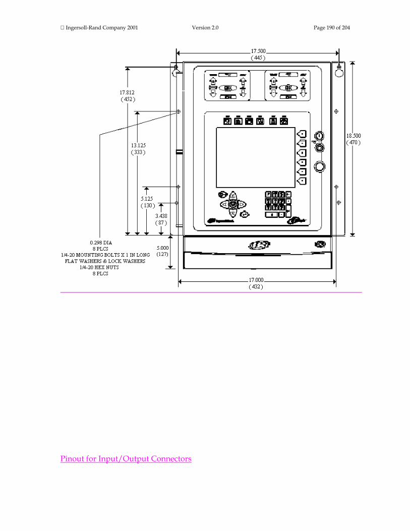
Ingersoll-Rand Company 2001 Version 2.0 Page 190 of 204
Pinout for Input/Output Connectors
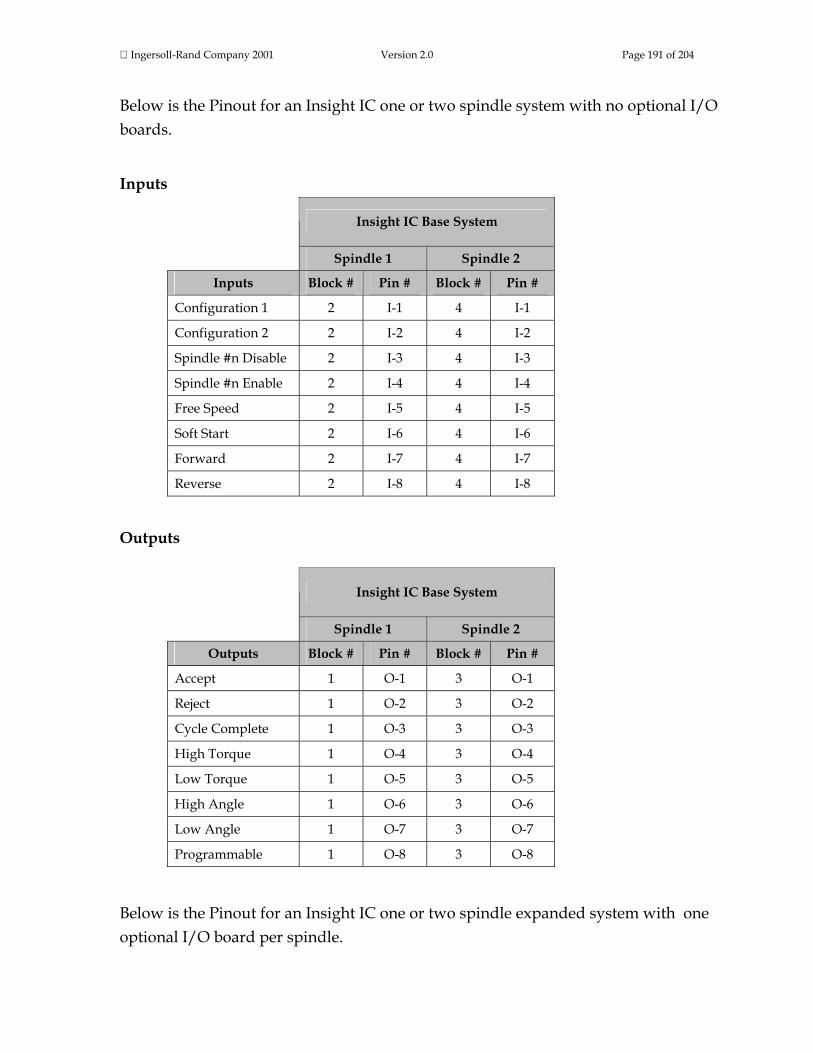
Ingersoll-Rand Company 2001 Version 2.0 Page 191 of 204
Below is the Pinout for an Insight IC one or two spindle system with no optional I/O boards.
Inputs
Insight IC Base System
Spindle 1 Spindle 2
Inputs Block # Pin # Block # Pin #
Configuration 1 2 I-1 4 I-1
Configuration 2 2 I-2 4 I-2
Spindle #n Disable 2 I-3 4 I-3
Spindle #n Enable 2 I-4 4 I-4
Free Speed 2 I-5 4 I-5
Soft Start 2 I-6 4 I-6
Forward 2 I-7 4 I-7
Reverse 2 I-8 4 I-8
Outputs
Insight IC Base System
Spindle 1 Spindle 2
Outputs Block # Pin # Block # Pin #
Accept 1 O-1 3 O-1
Reject 1 O-2 3 O-2
Cycle Complete 1 O-3 3 O-3
High Torque 1 O-4 3 O-4
Low Torque 1 O-5 3 O-5
High Angle 1 O-6 3 O-6
Low Angle 1 O-7 3 O-7
Programmable 1 O-8 3 O-8
Below is the Pinout for an Insight IC one or two spindle expanded system with one optional I/O board per spindle.

Ingersoll-Rand Company 2001 Version 2.0 Page 192 of 204
Inputs
Insight IC Expanded System
Spindle 1 Spindle 2
Inputs Block # Pin # Block # Pin #
Configuration 1 2 I-1 4 I-1
Configuration 2 2 I-2 4 I-2
Configuration 3 2 I-3 4 I-3
Configuration 4 2 I-4 4 I-4
Configuration 5 2 I-5 4 I-5
Configuration 6 2 I-6 4 I-6
Configuration 7 2 I-7 4 I-7
Configuration 8 2 I-8 4 I-8
Spindle #n Enable 6 I-1 10 I-1
Spindle #n Disable 6 I-2 10 I-2
Gang Reset 6 I-3 10 I-3
Config Reset 6 I-4 10 I-4
Safety Latch 6 I-5 10 I-5
Limit Switch In 6 I-6 10 I-6
Limit Switch Out 6 I-7 10 I-7
Bypass Spindle 6 I-8 10 I-8
Free Speed 8 I-1 12 I-1
Soft Start 8 I-2 12 I-2
Forward 8 I-3 12 I-3
Reverse 8 I-4 12 I-4
Not Available 8 I-5 12 I-5
Not Available 8 I-6 12 I-6
Not Available 8 I-7 12 I-7
Not Available 8 I-8 12 I-8
Outputs Insight IC Expanded System

Ingersoll-Rand Company 2001 Version 2.0 Page 193 of 204
Spindle 1 Spindle 2
Outputs Block # Pin # Block # Pin #
Accept 1 O-1 3 O-1
Reject Buzzer 1 O-2 3 O-2
High Torque 1 O-3 3 O-3
High Angle 1 O-4 3 O-4
Low Torque 1 O-5 3 O-5
Low Angle 1 O-6 3 O-6
Gang Complete 1 O-7 3 O-7
Cycle Complete 1 O-8 3 O-8
Reject 5 O-1 9 O-1
Stats Alarm 5 O-2 9 O-2
Programmable 5 O-3 9 O-3
Programmable 5 O-4 9 O-4
Programmable 5 O-5 9 O-5
Programmable 5 O-6 9 O-6
Programmable 5 O-7 9 O-7
Programmable 5 O-8 9 O-8
Programmable 7 O-1 11 O-3
Programmable 7 O-2 11 O-3
Programmable 7 O-3 11 O-3
Programmable 7 O-4 11 O-3
Programmable 7 O-5 11 O-3
Programmable 7 O-6 11 O-3
Programmable 7 O-7 11 O-3
Programmable 7 O-8 11 O-3
Below is the Pinout for an Insight IC one spindle expanded system with two optional I/O boards.
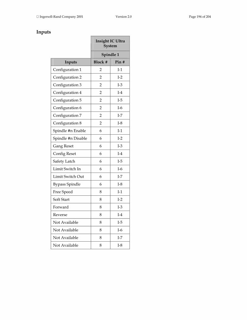
Ingersoll-Rand Company 2001 Version 2.0 Page 194 of 204
Inputs
Insight IC Ultra
System
Spindle 1
Inputs Block # Pin #
Configuration 1 2 I-1
Configuration 2 2 I-2
Configuration 3 2 I-3
Configuration 4 2 I-4
Configuration 5 2 I-5
Configuration 6 2 I-6
Configuration 7 2 I-7
Configuration 8 2 I-8
Spindle #n Enable 6 I-1
Spindle #n Disable 6 I-2
Gang Reset 6 I-3
Config Reset 6 I-4
Safety Latch 6 I-5
Limit Switch In 6 I-6
Limit Switch Out 6 I-7
Bypass Spindle 6 I-8
Free Speed 8 I-1
Soft Start 8 I-2
Forward 8 I-3
Reverse 8 I-4
Not Available 8 I-5
Not Available 8 I-6
Not Available 8 I-7
Not Available 8 I-8

Ingersoll-Rand Company 2001 Version 2.0 Page 195 of 204
The Ultra System has additional inputs reserved for future expansion on: Block 10 Pins I-1 thru I-8 AND Block 12 Pins I-9 thru I-16
Outputs
Insight IC Ultra
System
Spindle 1
Outputs Block # Pin #
Accept 1 O-1
Reject Buzzer 1 O-2
High Torque 1 O-3
High Angle 1 O-4
Low Torque 1 O-5
Low Angle 1 O-6
Gang Complete 1 O-7
Cycle Complete 1 O-8
Reject 5 O-1
Stats Alarm 5 O-2
Programmable 5 O-3
Programmable 5 O-4
Programmable 5 O-5
Programmable 5 O-6
Programmable 5 O-7
Programmable 5 O-8
Programmable 7 O-1
Programmable 7 O-2
Programmable 7 O-3
Programmable 7 O-4
Programmable 7 O-5
Programmable 7 O-6
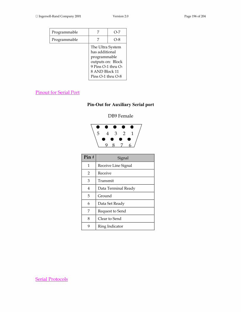
Ingersoll-Rand Company 2001 Version 2.0 Page 196 of 204
Programmable 7 O-7
Programmable 7 O-8
The Ultra System has additional programmable outputs on: Block 9 Pins O-1 thru O-8 AND Block 11 Pins O-1 thru O-8
Pinout for Serial Port
Pin-Out for Auxiliary Serial port
DB9 Female
5 4 3 2 1
9 8 7 6
Pin # Signal
1 Receive Line Signal
2 Receive
3 Transmit
4 Data Terminal Ready
5 Ground
6 Data Set Ready
7 Request to Send
8 Clear to Send
9 Ring Indicator
Serial Protocols

Ingersoll-Rand Company 2001 Version 2.0 Page 197 of 204
Host Data Out Serial Protocol
The following is the output structure for the Insight’s serial port when “Host Data out” has been selected in the Set-Up System Initialization screen. One line of data will be produced for every request sent by the host. The data is in the following format. After a request has been sent by the host and it receives the data, it must send the address number along with an ACK to the controller, to acknowledge that it has received the data. eeSSCCMMDDYYhhmmhhhhhjkkkkklmmnn<CR><LF> ee Address Address No. of Insight sent in “Multi Drop Address” entry box SS Spindle Number CC Configuration Number MMDDYY Month, Day, Year hhmm Hour, Minutes ( 24 hr time ) hhhhh Torque Four digits plus decimal point j Torque status space=OK, H=High, L=Low, kkkkk Angle Five digits l Angle status space=OK, H=High, L=Low, mm Cycle Last two digits of the cycle count nn Check sum Two digits Mod 256 To request data Host sends message AASSCC<CR><LF> Where AA is Insight Address Number, SS is Spindle number and CC in the configuration number. System responds with data stream above if there is data. If there is no data, then the controller will respond with “AA@@@@” where AA is the address No. To clear the Host buffer for a configuration send the command AASSCC01<CR><LF> To clear the Host buffer for a all configuration of a spindle, send the command AASSCC02<CR><LF>

Ingersoll-Rand Company 2001 Version 2.0 Page 198 of 204
E.O.R. (End of Run) Data Out Protocol
The following is the output structure for the Insight’s serial port when “E.O.R. Data out” has been selected in the Set-Up System Initialization screen. One line of data will be produced for every valid cycle detected by the Insight. The data will appear on the serial line the moment the cycle has ended. MM/DD/YY^hh:mm:ss^S^CC^cccccc^TTTTTF^aaaafnn<CR><LF> Where ^ is a Space MM is the month the cycle occurred DD is the day the cycle occurred YY is the day the cycle occurred hh:mm:ss is the hours minutes and seconds that the cycle occurred S is the spindle number of the cycle CC is the configuration number of the cycle cccccc is the cycle number TTTTT is the torque reading ( 4 digits with a decimal place) of the cycle F is the status flag for the torque reading: space = ok, H = high, L = low aaaa is the angle reading of the cycle f is the status flag for the angle reading: space = ok, H = high, L = low nn Two digit Check sum ( Mod 256 )

Ingersoll-Rand Company 2001 Version 2.0 Page 199 of 204
Definition of Statistical Parameters
INSIGHT IC's statistics functions allow you to acquire meaningful information about your fastening and assembly operations. Most often you will use these functions to analyze empirical data that is "real world" data from your fastening production line to verify that you are meeting existing specifications. However, these statistics functions can also be useful in developing specifications. In these situations you would conduct controlled experiments to systematically vary tightening parameters, and use the statistics functions to help understand the results. This section briefly defines and explains Insight's statistics functions. You may want to consult statistics reference books for additional information on what these functions mean and how they are used for data analysis. In addition, Ingersoll-Rand's applications engineers are available to help you make full use of not only statistics, but also all of the Insight IC Tightening System's capabilities. Remember that statistics are calculated independently for each spindle and for each spindle configuration. Remember also that you can calculate statistics for a population (all values in memory for that spindle and configuration) or for a sample of that population. Clearing the statistics stored in memory will reset the population and sample counters for the statistics only, the raw torque and angle values are retained in Insight's memory. The mean, also called the average, is a measure of central tendency. Mean = X = Sum of readings/Number of readings Sigma (σ) is the symbol for Standard Deviation, which is defined as the square root of the Variance. Variance is a measure of the degree to which the numbers in a list are spread out, that is whether they are close to or far from the Mean. The units of Variance are the square of the units of the data (for example foot-pounds squared), which makes them less intuitive and sometimes harder to interpret. Since a is the square root of Variance, it has the advantage of having the same units as the original data. σ = square root( Σ i=1,n(Xi-X)2/n-1)

Ingersoll-Rand Company 2001 Version 2.0 Page 200 of 204
Six Sigma (6σ) is six times the standard deviation, as calculated above. While that is the simple definition of six sigma, its significance is that it is an important performance measure for a recent movement within the quality control community to achieve significantly fewer manufacturing defects. For a normal bell-shaped distribution, the mathematical properties of the distribution mean that there is a 68% chance that a value (such as the final torque for a fastening) will be within one standard deviation ( 1 σ) of the mean. Achieving six sigma quality means that you have improved your process and it no longer follows a normal distribution. With six sigma there is a 99.9997% chance of a value being within one standard deviation of the mean. Expressed another way, six sigma quality means that there are <4 defects per 1,000,000 operations. The Insight IC also uses several other less conventional statistical measures. These are summarized below. Cp = (USL – LSL)/6σ Where USL = the upper set limit (or high limit) for a parameter, and LSL = the lower set limit (low limit) Cpk = the lesser of (X – LSL)/3σ or (USL – X)/3σ Capability = (6σ/ X) * 100 (expressed as a percent) CAM is a statistical parameter that is calculated for a series of fastenings. A total of 30 readings (six sample groups of five readings each) are usually used. Sample group #1 consists of five consecutive fastening values, sample group #2 consists of the next five consecutive fastening values, and so on up to sample group #6. For each sample group subtract the lowest reading from the highest reading. This value is called xI for sample group #1, x2 for sample group #2, and so on. These results are used to define a term called W, Average dispersion, where: W = (x1 + x2 + x3 +…+ xn)/ (number of sample groups (usually 6))

Ingersoll-Rand Company 2001 Version 2.0 Page 201 of 204
A constant is also used in the CAM calculation. That constant (called dS) varies with the number of sample groups, but for the usual six sample groups, dS = 1.746. Finally, CAM requires the torque or angle high limit and low limit (see USL and LSL defined above). Using these various values, CAM is calculated as follows: CAM = (USL – LSL) / (6*(W /dS))
Recommended Spare Parts
Recommended Spare Parts List
Part Number Description
PC89944185 Insight Operations Manual - CD ROM
PC89944326 Label, I/O Configuration A
PC89944334 Label, I/O Configuration B
PC89944342 Label, I/O Configuration C
PC89944359 Door assembly, 1 Spindle
PC89944367 Door assembly, 2 Spindle
PC89944375 Display,
PC89944375 Display, Color 10.4" LCD
PC89944383 Inverter, LCD Backlight
PC89944391 PCB Assembly, RISC Processor
PC89944409 PCB Assembly, 5V Power Supply
PC89944417 Power Supply, 12V DC - 60W
PC89944425 PCB Assembly, I/O
PC89944433 PCB Assembly, Cycle Status
PC89944466 Motor Controller Assembly
PC89944565 Connector, Terminal Block - 10 Pin
PC89944573 Power Supply, 24V DC - 100W

Ingersoll-Rand Company 2001 Version 2.0 Page 202 of 204
PC89944581 GFI/Circuit Breaker
PC89944599 Floppy Drive Kit
PC89944672 Cord, Power 120V-20A
PC89944680 Battery, Processor
PC89944748 Shipping Carton
PC89945331 Label, Operation Manual CD-ROM
PC89945349 Label, ICS Utility CD-ROM
PC89945455 Cover, Safety
PC89945497 ProfiBus Kit
PC89945505 DeviceNet Kit
PC89945521 PFCS Software
PC89945851 Modem Kit, PCMCIA
PC89945869 Modem, PCMCIA Card
PC89946669 Flash Memory, PCMCIA Card
PC89947618 115V Standard Cord Kit
PC89947626 115V Pigtail Kit
PC89947634 230V Pigtail Kit
PC89947642 Option, Standard I/O
PC89947659 Option, Single I/O Board
PC89947667 Option, 2 I/O Boards
PC89947675 Option, No Floppy Drive
PC89947683 Floppy Drive
PC89947691 Option, Standard Communications
PC89947840 Interface Card, ProfiBus
PC89947857 Interface Card, DeviceNet
PC89947865 Cord, Power - 230V 16A Pigtail
PC89947873 Cord, Power - 120V 20A Pigtail

Ingersoll-Rand Company 2001 Version 2.0 Page 203 of 204
Insight Shutdown Codes At the end of every cycle, the Insight IC logs a shutdown code to the cycle that indicates under what conditions the tool stopped. This shutdown code can be viewed in the cycle log by selecting Shutdown Code in the E.O.R. Filter screen of the Set-Up System Initialization menu screen. Below is a list of the Shutdown Codes.
Shutdown Code # Description
0 Normal Completion of Cycle
1 Trigger released before system shutdown
2 Tool stop on torque high
3 Tool stop on Angle high
4 Tool stop on yield override
5 Prevailing torque seating torque fail
6 Prevailing torque seating angle fail
7 Prevailing torque too high (next step target + prevailing > next step limit)
8 Prevailing torque sync shutdown (forced to shutdown because sync flag was set)
9 Min drag torque fail
10 Motor stalled (I2t limit reached)
11 Hall transition error (Hall fault)
12 Motor controller IGBT driver fault (bootstrap cap under voltage or IGBT short)
13 Over current (detected by software current loop)
14 Low bus voltage
15 Cycle timeout (cycle timeout time reached before end of cycle)
16 Display processor issued a STOP command to Motor controller
17 Tool was disconnected
18 Communication was lost (unable to send EOR or other asynchronous "event')
19 Bad torque reference (the torque step reference + tare-overshoot was greater than the step limit)

Ingersoll-Rand Company 2001 Version 2.0 Page 204 of 204
This is the end of the Services: System Specifications section and the end of the Insight IC Fastening System with Graphics Display manual. If you want additional information on this Insight system, click on another topic at the left. END OF DOCUMENT